Embed Size (px)
Citation preview

Journal of Advanced Research in Fluid Mechanics and Thermal Sciences
ISSN (online): 2289-7879 | Vol. 1, No. 1. Pages 1-10, 2014
1
Penerbit
Akademia Baru
Simulation of Film Cooling in the Leading Edge
Region of a Turbine Blade Using ANSYS CFX
M. R. Pairan*,a, N. Asmuinb and H. Sallehc
Centre for Energy and Environmental Study (CEIES),
Faculty of Mechanical and Manufacturing Engineering,
Universiti Tun Hussein Onn Malaysia (UTHM), Locked Bag 101, Parit Raja,
86400 Batu Pahat, Johor Darul Ta’zim *,[email protected], [email protected], [email protected]
Abstract – Film cooling is one from the many of cooling techniques applied to turbine blade. Gas
turbine uses film cooling technique to protect turbine blade from direct exposure to hot gas to avoid
wear and defects of the blade. The focus of this investigation is to investigate the effect of embedding
three different depths of trench at coolant holes geometry. Comparisons are made at three different
blowing ratios, which are 1.0, 1.25 and 1.5. Three configurations of leading edge with different depths,
which are Case A (0.0125D), Case B (0.0350D) and Case C (0.0713D), were compared to leading edge
without trench. The result shows that as blowing ratio increased from 1.0 to 1.2, the film cooling
effectiveness increased for leading edge without trench and also for all cases. However, when the
blowing ratio increased to 1.5, the film cooling effectiveness decreased for all cases. Overall, Case B
with blowing ratio of 1.25 has the best film cooling effectiveness with a significant improvement
compared to leading edge without trench and with trench for Case A and Case C. Copyright © 2014
Penerbit Akademia Baru - All rights reserved.
Keywords: Trench effect, Film cooling, Turbine blade
1.0 INTRODUCTION
Thermal efficiency of gas turbine engine can be efficiently improved by increasing the
temperature of turbine inlet. This high operative temperature affects the durability of blade.
Therefore, in order to prevent damage to the blade, film cooling techniques have been
developed. Applying the concept of film cooling effectiveness can avoid the blades from
failure or defect. This study focuses on the effect of different depths of trench. 3D
computational fluid dynamics (CFD) simulation using ANSYS software will be performed to
determine jet-mainstream interactions to better understand film effectiveness distributions. In
this study, the investigation was performed at a single mainstream Reynolds number based on
film-hole cylinder diameter of 8,550 at four different blowing ratios (1.0, 1.25, 1.5 and 2.0).
The result was then validated with a journal numerical study on a flat plate and leading edge
film cooling [1]. There are a lot of factors that should be considered to increase film cooling
effectiveness, such as inclination of the holes that are connected with the plenum. Yuen and
Martinez-Botas [2] reported a study where three angles (30o, 60 o and 90 o) were tested. From
the result, the best cooling characteristics was observed at 30o. With the objective to look for
a better film cooling technique, Lu et al. [3] investigated the effect of slot exit area and edge

Journal of Advanced Research in Fluid Mechanics and Thermal Sciences
ISSN (online): 2289-7879 | Vol. 1, No. 1. Pages 1-10, 2014
2
Penerbit
Akademia Baru
shape on film effectiveness measurements made on a flat plate. They found that a straight-
edge exit performed the best at a blowing ratio of BR=1.0, whereas a ramped exit enhanced the
adiabatic effectiveness levels at lower blowing ratios. Baldauf et al. [4] observed that initial
increase in η with increasing BR is expected due to the greater mass flow of coolant, whereas
the decrease in η for BR ≥ 0.85 is due to the coolant jet separating from the surface [4]. David
G. Bogard [5] mentioned that film effectiveness can be improved if the exit of the hole is
expanded so that coolant is slowed through a diffuser.
2.0 METHODOLOGY
In this study, ANSYS software was used to simulate film cooling at the leading edge involving
fluid flow and heat transfer based on simulation. Blowing ratio, BR, is defined as the ratio of
mass flux of the mainstream and the coolant. It is expressed as:
∞∞
=V
VBR cc
ρ
ρ (1)
Film cooling effectiveness is defined as:
∞
∞
−
−=
TT
TT
c
awη (2)
Mainstream conditions were maintained in all cases, and coolant flow rate was altered to
change the velocity of coolant. Coolant temperature was set at 321K and mainstream
temperature was fixed at 291K. The Reynolds number for the study was 8550 based on the
mainstream velocity and the diameter of the cooling hole.
A model was constructed using SOLIDWORKS software. Figure 1 shows the computational
domain of semi-cylindrical leading edge model with a flat alter body. Within the cylindrical
wall of 80 mm diameter (D=10d) were plenum and three rows of film cooling holes arranged
in a staggered fashion. The diameter of each hole was 8 mm (d=8 mm). The inclination angle
of holes was 30o relative to span-wise direction.
Figure 1: Schematic for the leading edge
Periodic condition was imposed to the span-wise direction so that only three film cooling holes
need to be examined. Figure 2 shows the separation angle between hole 1 and hole 2 in the x-

Journal of Advanced Research in Fluid Mechanics and Thermal Sciences
ISSN (online): 2289-7879 | Vol. 1, No. 1. Pages 1-10, 2014
3
Penerbit
Akademia Baru
y plane of 30o and the separation angle between hole 2 and hole 3 in the x-y plane of 35o. The
pitch between the holes was 31 mm. Figure 3 illustrates three different cases of trench
embedded at coolant exit holes.
Figure 2: Angles for coolant holes
Case A (0.0125D) Case B (0.0350D) Case C (0.0713D)
Figure 3: Three configurations of leading edges with different depths
In the computational domain, boundary conditions were set at the domain. Mainstream
conditions were maintained for all cases. The magnitude of coolant velocity varies by altering
blowing ratio for each case.
Table 1: Boundary conditions and numerical set up
Item Physical Properties
General Condition Steady state
Incompressible
Non radiation
Turbulence Model k-ω SST Model
Inlet Mainstream temperature (K) 291
Coolant (K) 321
Mainstream inlet velocity (m/s) 15.955
Coolant
Hole
Plenum
Hole 1
Hole 2
Hole 3

Journal of Advanced Research in Fluid Mechanics and Thermal Sciences
ISSN (online): 2289-7879 | Vol. 1, No. 1. Pages 1-10, 2014
4
Penerbit
Akademia Baru
3.0 RESULTS AND DISCUSSION
The current numerical work was validated by comparing the results with the numerical data
from the numerical study on flat plate and leading edge film cooling [1]. This was done by
laterally observing the average film cooling effectiveness at the leading edge without trench
case. From Equation 3, the standard deviation between simulation data was about 0.08, which
was relatively small, thus giving high validity to the present simulation. Hence, the current
simulation approach was satisfactory and validated. The simulation and experimental averaged
effectiveness distributions are shown in Figure 4.
( )n
UUinumi xx
2
exp,,−∑
=σ (3)
where
numixU,
= local numerical averaged effectiveness
exp,ixU = local experimental averaged effectiveness
n = number of data
Figure 4: The validation plot for averaged effectiveness between simulation and experiment
at BR=1.0
Three models of leading edges with different depths of trench and leading edge without trench
were tested under difference blowing ratios (BR) of 1.0, 1.25 and 1.5. Figure 5 shows the
quantitative values for film cooling effectiveness at BR=1.0. It shows that the entire leading
edge configuration with trench yielded much higher film cooling effectiveness values
compared to leading edge without trench. However, the film cooling effectiveness values for
all cases of leading edge with trench was almost similar each other. It shows that the effect of

Journal of Advanced Research in Fluid Mechanics and Thermal Sciences
ISSN (online): 2289-7879 | Vol. 1, No. 1. Pages 1-10, 2014
5
Penerbit
Akademia Baru
different depths of trench height on film cooling effectiveness was small at BR=1.0. Figure 6
shows the coolant spread on the leading edge surface. From the figure, it can be observed that
there is more coolant spreading on the leading edge surface for leading edge with trench
compared to the leading edge without trench.
Figure 5: Lateral film cooling effectiveness at BR=1.0 (left) and leading edge without
trench(right)
Case A Case B Case C
Figure 6: Distributions of film cooling effectiveness for leading edge without trench, Case A,
Case B, and Case C at BR=1.0.
The effect of embedding trench at the leading edge is represented by Figures 7 and 8. The
velocity vector shows that for leading edge without trench, the jet coolant directly exited the
coolant holes, which was then mixed with the mainstream velocity. This phenomenon presents
low averaged film cooling effectiveness to the leading edge without trench. For example Case

Journal of Advanced Research in Fluid Mechanics and Thermal Sciences
ISSN (online): 2289-7879 | Vol. 1, No. 1. Pages 1-10, 2014
6
Penerbit
Akademia Baru
A, it appears that the coolant exiting the holes and then the coolant jet filled the trench before
being spread outside the trench area.
Figure 7: Velocity vector (left) and temperature (right) for leading edge without trench at
BR=1.0.
Figure 8: Velocity vector (left) and temperature (right) for leading edge with trench at
BR=1.0.
When the coolant jet struck along the trench edge, it affected the change of velocity. The
velocity after the coolant jet struck the trench edge was higher compared when the coolant jet
did not strike the edge upon exiting. Thus, the coolant spread outside the trench and covered
larger area at the leading edge. It was observed that less interaction occurred between coolant
jet and mainstream in the jet exit region. These results in higher effectiveness at the jet exit.
However, in the downstream, the film thickness became lesser and led to lower effectiveness.

Journal of Advanced Research in Fluid Mechanics and Thermal Sciences
ISSN (online): 2289-7879 | Vol. 1, No. 1. Pages 1-10, 2014
7
Penerbit
Akademia Baru
As the BR increased to 1.25, the film cooling effectiveness increased for all cases including
the leading edge without trench. As can be seen in Figure 9, all the values of film cooling
effectiveness increased, where the highest film cooling effectiveness was achieved in Case B,
followed by the leading edge without trench, Case C and Case A. This phenomenon happened
because as the blowing ratio increased to 1.25, the coolant velocity also increased, thus
enhanced the film cooling effectiveness for leading edge without trench compared to the
blowing ratio 1.0. From the graph, as the blowing ratio increased, the film cooling
effectiveness also increased. This phenomenon is proven by looking at the film cooling
effectiveness values for the leading edge without trench at blowing ratio of 1.25 and compared
to the value of film cooling effectiveness for the leading edge without trench at blowing ratio
of 1.0. Hence, it is shown that when the blowing ratio increases, the effectiveness of film
cooling at the leading edge without trench also increases.
Figure 9: Lateral film cooling effectiveness at BR=1.25 (left) and leading edge without
trench (right)
For Case A, Case B and Case C, the film cooling effectiveness did not change significantly.
The highest film cooling effectiveness was observed for Case B, whereas the lowest film
cooling effectiveness was determined for Case A. This concludes that when the coolant enters
the medium trench with medium blowing ratio, it will produce the best film cooling
effectiveness. From Figure 10, it can be seen that for each Case A, Case B and Case C, as the
coolant exiting the holes, the coolant jet will fill the trench before exiting to the leading edge
surface. At some point, when the coolant jet fills the trench completely, it will strike the trench
edge, then the velocity of the coolant jet becomes higher and causes the coolant to spread
widely. Consequently, it causes higher film cooling effectiveness, and this phenomenon is
explained by Figures 7 and 8. It is observed that the effects of trench Case B at blowing ratio
1.25 helped the coolant jet to spread widely as compared to all cases. When the coolant spread
widely, more interaction occurs between the coolant jet and the mainstream in the jet exit
region. This results in higher effectiveness at the jet exit. However, in the downstream, the
film thickness becomes thinner and lower.
Journal of Advanced Research in Fluid Mechanics and Thermal Sciences
ISSN (online): 2289-7879 | Vol. 1, No. 1. Pages 1-10, 2014
8
Penerbit
Akademia Baru
Case A Case B Case C
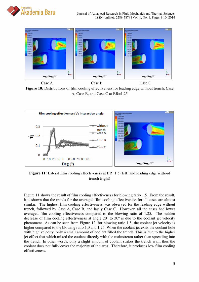
Figure 10: Distributions of film cooling effectiveness for leading edge without trench, Case
A, Case B, and Case C at BR=1.25
Figure 11: Lateral film cooling effectiveness at BR=1.5 (left) and leading edge without
trench (right)
Figure 11 shows the result of film cooling effectiveness for blowing ratio 1.5. From the result,
it is shown that the trends for the averaged film cooling effectiveness for all cases are almost
similar. The highest film cooling effectiveness was observed for the leading edge without
trench, followed by Case A, Case B, and lastly Case C. However, all the cases had lower
averaged film cooling effectiveness compared to the blowing ratio of 1.25. The sudden
decrease of film cooling effectiveness at angle 20o to 30o is due to the coolant jet velocity
phenomena. As can be seen from Figure 12, for blowing ratio 1.5, the coolant jet velocity is
higher compared to the blowing ratio 1.0 and 1.25. When the coolant jet exits the coolant hole
with high velocity, only a small amount of coolant filled the trench. This is due to the higher
jet effect that which mixed the coolant directly with the mainstream rather than spreading into
the trench. In other words, only a slight amount of coolant strikes the trench wall, thus the
coolant does not fully cover the majority of the area. Therefore, it produces low film cooling
effectiveness.

Journal of Advanced Research in Fluid Mechanics and Thermal Sciences
ISSN (online): 2289-7879 | Vol. 1, No. 1. Pages 1-10, 2014
9
Penerbit
Akademia Baru
Case A Case B Case C
Figure 12: Distributions of film cooling effectiveness for leading edge without trench, Case
A, Case B, and Case C at BR=1.5
4.0 CONCLUSION
Three types of trenches with different depths were tested with three blowing ratios of 1.0, 1.25
and 1.5. The result shows that with medium depth of trench, the coolant spreads widely on the
leading edge and covers a larger area. With this characteristic of coolant spreading, the leading
edge with medium depth of trench enhances film cooling effectiveness as compared to all cases
with and without trench. This means the depth of trench does affect the film cooling
effectiveness. Hence, it can be concluded that the film cooling performance can be significantly
improved by controlling the blowing ratio and the depth of trench. It is noted that the blowing
ratio and depth of trench has a very strong effect on film cooling effectiveness.
REFERENCES
[1] E. Sakai, T. Takahashi, K. Funazaki, H.B. Salleh, K. Watanabe, Numerical Study on Flat
Plate and Leading Edge Film Cooling, Proceedings of the ASME Turbo Expo 2009:
Power for Land Sea and Air, ASME, 2009, pp. 491-503.
[2] Y. Lu, H. Nasir, S.V. Ekkad, Film-Cooling From a Row of Holes Embedded in
Transverse Slots, Proceedings of the ASME Turbo Expo 2005: Power for Land Sea and
Air, ASME, 2005, pp. 585-592.
[3] C.H.N. Yuen, R.F. Martinez-Botas, Film cooling characteristics of a single round hole at
various streamwise angles in a crossflow Part II: heat transfer coefficients, International
Journal of Heat and Mass Transfer 46 (2) (2003) 237-249.
[4] S. Baldauf, M. Scheurlen, A. Schulz, S. Wittig, Correlation of Film-Cooling
Effectiveness from Thermographic Measurements at Enginelike Conditions, Journal of
Turbomachinery 124 (4) (2002) 686-698.

Journal of Advanced Research in Fluid Mechanics and Thermal Sciences
ISSN (online): 2289-7879 | Vol. 1, No. 1. Pages 1-10, 2014
10
Penerbit
Akademia Baru
[5] D. G. Bogard, Mechanical Engineering Department University of Texas at Austin, TX
78712.