Embed Size (px)
Citation preview

REV052720
SimpliPhi Power, Inc. | 3100 Camino Del Sol | Oxnard, CA 93030, USA | (805) 640-6700 | [email protected] | SimpliPhiPower.com
| 1 |
SimpliPhi Wiring Guide
1.0 – Online Resources The Product Documentation section of SimpliPhi’s web site (https://simpliphipower.com/product-documentation/) includes Specification Sheets, Warranties, Installation & Operator’s Manuals, and Integration Guides for all SimpliPhi’s current and legacy products.
SimpliPhi’s YouTube channel (https://www.youtube.com/channel/UCcuCaLT_G3Hhumteh-pI5yg/videos) has instructional videos, including:
How to connect a lug to the terminals on a SimpliPhi Power battery: https://www.youtube.com/watch?v=63hwvoZC0Zc
Paralleling PHI Batteries with Threaded Studs Using Battery Cables: https://www.youtube.com/watch?v=Xk_tuVukUx0
Connecting a busbar to terminals on a SimpliPhi battery: https://www.youtube.com/watch?v=7PamjYbd8TQ
Paralleling PHI Batteries using Busbars: https://www.youtube.com/watch?v=l_ABYDNfE74
2.0 – Technical Support SimpliPhi Technical Support (805-640-6700 x 1, [email protected]) is available to take any questions regarding this Guide or general installation questions.
3.0 – General Safety Instructions • Do not operate if the PHI Battery has been damaged in any way during shipping or otherwise. • To reduce the chance of short-circuits, always use insulated tools when installing or working with PHI
batteries or other electrical equipment. • Remove personal metal items such as rings, bracelets, necklaces, and watches when working with PHI
batteries and electrical equipment. Wear insulated gloves and rubber shoes. • PHI Batteries pose some risk of shock or sparking during the installation and initial wiring and connection
process. This is consistent with all other battery-based storage formats. For batteries with threaded stud connections, be sure the built-in breaker is in the “OFF” position to minimalize the risk of shock or sparks during the installation and commissioning of the system.
• To avoid a risk of fire and electric shock, make sure that existing system wiring is in good condition and that the wire is not undersized. Do not operate the PHI Battery in conjunction with damaged or substandard wiring.
4.0 – Parallel Wiring
CAUTION: PHI Batteries are designed to serve at fixed voltages and cannot be wired in series to increase the battery bank’s voltage. Wiring the PHI Batteries in series will result in damage to the PHI Battery’s protective circuitry and will Void the Warranty. PHI batteries are designed for parallel wiring only to increase the battery bank’s storage capacity.

REV052720
SimpliPhi Power, Inc. | 3100 Camino Del Sol | Oxnard, CA 93030, USA | (805) 640-6700 | [email protected]| SimpliPhiPower.com
| 2 |
Storage Capacity and total available Amperage is increased incrementally with the number of units wired in Parallel. For example, two PHI 3.8 kWh-51.2Vnominal (75Ah) Batteries wired in parallel are rated at a combined 7.6 total kWh, 51.2 Volts DC and 150Ah. Each PHI 3.8 kWh-51.2Vnominal Battery also has a maximum continuous discharge rate of 37.5 Amps DC and paralleling two of these batteries incrementally increases the maximum continuous charge and discharge rate. The two paralleled PHI 3.8 kWh-51.2Vnominal batteries have a combined maximum continuous charge and discharge rate of 75 Amps DC (2 × 37.5ADC).
5.0 – PHI Battery Parallel Wiring Methods Parallel wiring can be accomplished in one of two ways:
1. Method #1: Pairs of battery cables (one positive, one negative) connect between each PHI Battery in the battery bank and the positive and negative DC busbars, plates, or terminal blocks. If the DC busbars, plates, or terminal blocks are located somewhere other than the paired inverter’s power panel (diagramed in Figure 1.0), additional connections may be required between a battery combiner box or terminal blocks and the Balance of System (BoS) equipment (see Figure 2.0). Refer to Sections 6.0 and 6.1 of this Guide for further instruction. Figure 1.0 - Four PHI Batteries Paralleled in a Schneider Conext Power Distribution Panel (PDP)

REV052720
SimpliPhi Power, Inc. | 3100 Camino Del Sol | Oxnard, CA 93030, USA | (805) 640-6700 | [email protected]| SimpliPhiPower.com
| 3 |
Modified from Schneider Electric’s Conext XW PRO Installation Guide. Wiring differs when Conext Battery Monitor is included in the system. All Battery-to-DC Busbar cables are the same length and gauge.
Figure 2.0 – Twelve PHI Batteries Paralleled in a MidNite Solar MNLBC Lithium Battery Combiner Box with a single Positive Output and a single Negative Output leaving the Combiner Box, to the BoS
Photo courtesy of Mike Swenson (Schneider Electric).

REV052720
SimpliPhi Power, Inc. | 3100 Camino Del Sol | Oxnard, CA 93030, USA | (805) 640-6700 | [email protected]| SimpliPhiPower.com
| 4 |
2. Method #2: Busbars are attached directly to the terminals of multiple PHI Batteries (see Figure 3.0). Battery cables then connect between these positive and negative busbars and the positive and negative DC busbars, plates, or terminal blocks. If the DC busbars, plates, or terminal blocks are located somewhere other than the paired inverter’s power panel (see Figure 4.0), additional connections may be required between a battery combiner box or terminal blocks and the BoS equipment (see Figure 5.0). Refer to Sections 6.0 and 6.2 of this Guide for further instruction.
Figure 3.0 – Busbars Attached Directly to Multiple PHI Batteries’ Terminals
Figure 4.0 – Three PHI Batteries Paralleled Using Direct Bussing

REV052720
SimpliPhi Power, Inc. | 3100 Camino Del Sol | Oxnard, CA 93030, USA | (805) 640-6700 | [email protected]| SimpliPhiPower.com
| 5 |
Figure 5.0 – Six Total PHI Batteries are Directly Bussed in Two Sets of Three, then Paralleled Using Cabling to a Single Positive Terminal Block and a Single Negative Terminal Block
6.0 – Cable or Busbar Ampacity Ratings PHI battery cable leads are typically sized at 4 AWG. This sizing is according to the battery’s 80ADC built-in breaker and therefore assumes a maximum current of 80 Amps flowing to or from an individual battery. While many other factors may be considered when sizing battery cables or interconnecting busbars, as is explained in further detail in this Guide’s Appendix, SimpliPhi recommends using 4 AWG cable or interconnecting busbars provided by SimpliPhi (when applicable) to ensure system efficiency and robustness.

REV052720
SimpliPhi Power, Inc. | 3100 Camino Del Sol | Oxnard, CA 93030, USA | (805) 640-6700 | [email protected]| SimpliPhiPower.com
| 6 |
7.0 – Cable Wiring Batteries with Threaded Studs (Wiring Method #1) When parallel wiring PHI batteries using cables (from individual PHI Batteries to DC busbars or plates or terminal blocks), make sure all wires from each PHI battery to common busbars, plates, or terminal blocks are the same length and gauge. Matching cable lengths and gauges balances the load across (all) PHI Batteries in the installation.
Figure 8.0 – Two PHI Batteries in Parallel
Figure 9.0 - Four PHI Batteries in Parallel
Although lead acid batteries are typically wired using battery-to-battery interconnecting cables, SimpliPhi asks that PHI Batteries NOT be wired in this way.
Figure 10.0 – Incorrect Parallel Wiring for PHI Batteries

REV052720
SimpliPhi Power, Inc. | 3100 Camino Del Sol | Oxnard, CA 93030, USA | (805) 640-6700 | [email protected]| SimpliPhiPower.com
| 7 |
CAUTION: Identical wire lengths and identical wire gauges from each PHI Battery in a PHI Battery bank is a critical feature of parallel power storage systems that must be adhered to throughout all parallel wiring instructions. Failure to properly wire the PHI Batteries in parallel will Void the Warranty.
3/8” (10mm) lugs fit on the terminal posts of batteries with threaded studs (such as PHI 3.8, PHI 2.9, etc.). Battery cables can often be ordered to include these 3/8” lugs.
Battery cables may be sourced from many of SimpliPhi’s distributors (listed below), from Spartan Power (https://spartanpower.com/product/custom-battery-cables/), or from any other battery cable supplier. Again, battery interconnect cables are not typically used as these are usually not long enough to reach from each individual battery in the battery bank to the common DC busbar or plate or terminal block.
altE: https://www.altestore.com/store/cables-wiring/battery-to-inverter-cables-c464/
Northern Arizona Wind & Sun: https://www.solar-electric.com/residential/wiring-cables/battery-inverter-cables.html
Soligent: https://dealer.soligent.net/index.cfm?page=categories&categoryid=13
WESCO: https://buy.wesco.com/browse/json/search/Single-Conductor-Cable/_/N-1m5g08d
Rematek Energie: https://rematek-energie.com/eng/Wiring/Battery-cable/wholesale-Montreal-Quebec-Ontario-Canada/c/14/s/44/pg/3
HES PV: https://hespv.ca/residential-solar-energy-systems/solar-off-grid-canada/batteries/battery-accessories
Helpful Tips:
• Determine the cable length for the PHI Battery terminal farthest from the common busbar or plate or terminal block first.
• Wire length should be kept as short as practical. • Additional cabling or slack that remains with the shorter distance runs can be coiled
and secured with Zip Ties. • Positive wire runs should be separated from negative wire runs in separate conduit.
REV052720
SimpliPhi Power, Inc. | 3100 Camino Del Sol | Oxnard, CA 93030, USA | (805) 640-6700 | [email protected]| SimpliPhiPower.com
| 8 |
• MidNite Solar produces the MNLB Lithium Battery Combiner (rated at 250 Amps MAX) and the MNBCB 1000/50 Battery Combiner (rated at 1,000 Amps MAX).
• If wiring battery cables directly to the inverter’s panel (as in Figure 1.0), consult the inverter manufacturer regarding negative wiring to a DC Negative Busbar versus a DC shunt. Refer to the third-party manufacturer’s product documentation for guidance regarding acceptable wire sizes and torque specifications when wiring to that manufacturer’s equipment.
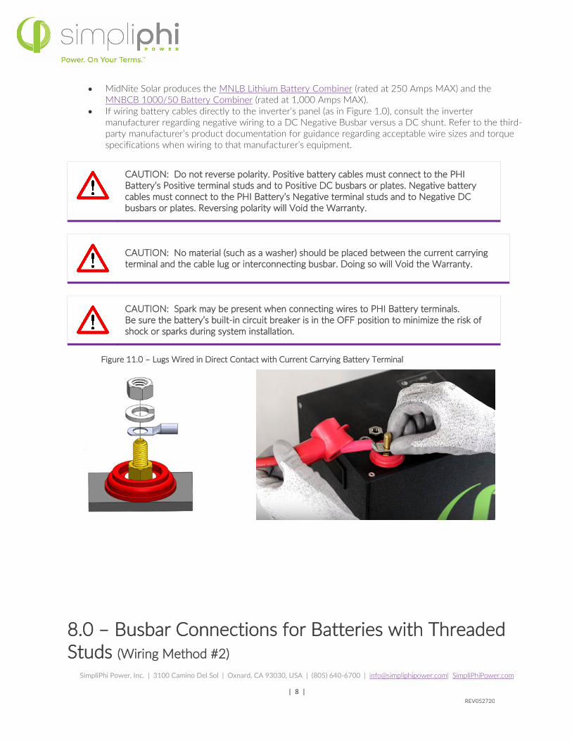
CAUTION: Do not reverse polarity. Positive battery cables must connect to the PHI Battery’s Positive terminal studs and to Positive DC busbars or plates. Negative battery cables must connect to the PHI Battery’s Negative terminal studs and to Negative DC busbars or plates. Reversing polarity will Void the Warranty.
CAUTION: No material (such as a washer) should be placed between the current carrying terminal and the cable lug or interconnecting busbar. Doing so will Void the Warranty.
CAUTION: Spark may be present when connecting wires to PHI Battery terminals. Be sure the battery’s built-in circuit breaker is in the OFF position to minimize the risk of shock or sparks during system installation.
Figure 11.0 – Lugs Wired in Direct Contact with Current Carrying Battery Terminal
8.0 – Busbar Connections for Batteries with Threaded Studs (Wiring Method #2)

REV052720
SimpliPhi Power, Inc. | 3100 Camino Del Sol | Oxnard, CA 93030, USA | (805) 640-6700 | [email protected]| SimpliPhiPower.com
| 9 |
PHI Batteries can be paralleled using common bussing directly attached to the batteries’ terminals. Best practice involves wiring the battery leads to opposite ends of the busbars, as illustrated in Figure 12.0 below. All groups of interconnected battery “strings” within a single PHI battery bank must include the same number of batteries per “string.”
Interconnecting busbars for paralleling either two (SKU #BB-2) or three (SKU #BB-3) PHI batteries with threaded studs are available from any of SimpliPhi’s distributors (https://simpliphipower.com/distributors/) at an additional cost.
Figure 12.0 – SKU BB-3
Interconnecting battery busbars for “strings” of more than two or three batteries must be custom ordered. SimpliPhi recommends contacting Storm Power Components regarding such requests:
Paige Elgin, Inside Sales Representative, [email protected], (423) 334-4800.
Storm Power requests that the customer provide full engineering diagrams with measurements included, in order to quote the exact items needed. Pre-drilled holes or slots (for fitting busbars directly onto the batteries’ terminals) and insulators may be requested. Due to the minimal amount of heat generated from the batteries, SimpliPhi does not require any spacing between the PHI batteries. However, from a logistical standpoint, it is advised to either (a) request pre-drilled slots in the busbars instead of holes to account for slight variations between batteries’ dimensions, or (b) account for a small amount of spacing between batteries and request pre-drilled holes in the busbars that account for that small amount of spacing.
Refer to Storm Power Component’s Quick Copper Busbar Design Selector for guidance on ampacity ratings per busbar dimensions: https://stormpowercomponents.com/technical-library/ampacity-and-specifications-tables/quick-busbar-design-selector-ampacity-chart/.

REV052720
SimpliPhi Power, Inc. | 3100 Camino Del Sol | Oxnard, CA 93030, USA | (805) 640-6700 | [email protected]| SimpliPhiPower.com
| 10 |
Helpful Tips:
• SimpliPhi’s two-PHI battery busbars (SKU #BB-2) with a 50°C rise are rated at 455 ADC. Positive (red) and negative (black) busbars measure 9.37” x 1” x 3/16”.
• SimpliPhi’s three-PHI battery busbars (SKU #BB-3) with a 50°C rise are rated at 455 ADC. Positive (red) busbars measure 21.5” x 1” x 3/16” and negative (black) busbars measure 19.5” x 1” x 3/16”.
CAUTION: Again, no material (such as a washer) should be placed between the current carrying terminal and the interconnecting busbars. The interconnecting busbars are placed on the PHI Batteries’ terminals first, then the flat washer, lock washer, and nut are secured to the terminal posts.
CAUTION: Do not reverse polarity. Use a voltmeter to check polarity before making connections to the battery terminals. Reversing polarity will Void the Warranty.
9.0 – Battery Bank Expansion All equations in Section 6.0 must be reconsidered when adding new PHI batteries to an existing SimpliPhi battery bank. If there is a chance that the battery bank may be expanded upon in the future, consider upfront the appropriate battery cable, battery busbar, terminal block or DC busbar ratings required for the eventual battery bank.

REV052720
SimpliPhi Power, Inc. | 3100 Camino Del Sol | Oxnard, CA 93030, USA | (805) 640-6700 | [email protected]| SimpliPhiPower.com
| 11 |
Appendix - Cable or Busbar Ampacity Ratings A variety of factors are considered when sizing battery cables and/or busbars:
• Local electrical codes
• Ambient temperature
• Voltage drop
• Percentage of raceway filled
• The draw of the connected load(s)
This Guide puts aside the variables associated with local electrical codes, ambient temperature and voltage drop. Heavy gauge, high strand copper wire is the industry standard due to its stability, efficiency and overall quality. Due to the high degree of variability associated with these and other project factors, this Guide examines battery cable and/or busbar sizing according to the continuous electrical current of connected loads and charging sources only. The following cable or busbar sizing examples are not intended to substitute the National Electrical Code and/or local electrical codes.
For more information regarding voltage drop calculations for wiring distances greater than 10 feet (3 meters), see these links:
• https://www.altestore.com/howto/wire-sizing-tool-for-12-24-and-48-volt-dc-systems-a106/
• https://www.bluesea.com/support/articles/Circuit_Protection/1437/Part_1%3A_Choosing_the_Correct_Wire_Size_for_a_DC_Circuit
CAUTION: Sizing battery cables and/or busbars using this Guide’s methodology (according to connected loads alone) may result in the violation of local electrical codes. Defer to the electrical code of the local Authority Having Jurisdiction over this Guide’s Appendix.
1.0 –Battery Cable Ampacity Sizing Example 1: Examine Figure 1.0 and consider both the maximum current liable to be drawn from the 4-PHI 3.8 kWh-48V battery bank instantaneously, as well as the maximum amount of current used to potentially charge the battery bank. Whichever value is greater can be used to size the battery-to-inverter cables.
Assume: DC Loads = 0 Watts, Inverter AC Power Rating = 6,800 W, Inverter Charger Rating = 140 ADC, and MPPT Charge Controller Maximum Output = 60 ADC
1. Maximum current liable to be drawn from the battery bank
𝑀𝑀𝑀𝑀𝑀𝑀 𝐷𝐷𝐷𝐷 𝐷𝐷𝐶𝐶𝐶𝐶𝐶𝐶𝐶𝐶𝐶𝐶𝐶𝐶 𝐷𝐷𝐶𝐶𝐷𝐷𝐷𝐷 =𝑀𝑀𝑀𝑀𝑀𝑀 𝐷𝐷𝐷𝐷 𝑊𝑊𝐷𝐷𝐶𝐶𝐶𝐶 𝐷𝐷𝐶𝐶𝐷𝐷𝐷𝐷
𝐿𝐿𝐿𝐿𝐷𝐷𝐶𝐶𝐿𝐿𝐶𝐶 𝐵𝐵𝐷𝐷𝐶𝐶𝐶𝐶𝐶𝐶𝐶𝐶𝐵𝐵 𝐵𝐵𝐷𝐷𝐶𝐶𝐵𝐵 𝑉𝑉𝐿𝐿𝑉𝑉𝐶𝐶𝐷𝐷𝑉𝑉𝐶𝐶
𝑀𝑀𝑀𝑀𝑀𝑀 𝐷𝐷𝐷𝐷 𝑊𝑊𝐷𝐷𝐶𝐶𝐶𝐶 𝐷𝐷𝐶𝐶𝐷𝐷𝐷𝐷 =𝐼𝐼𝐶𝐶𝐼𝐼𝐶𝐶𝐶𝐶𝐶𝐶𝐶𝐶𝐶𝐶 𝑀𝑀𝐷𝐷 𝑂𝑂𝐶𝐶𝐶𝐶𝑂𝑂𝐶𝐶𝐶𝐶 𝑃𝑃𝐿𝐿𝐷𝐷𝐶𝐶𝐶𝐶 𝑊𝑊𝐷𝐷𝐶𝐶𝐶𝐶𝐿𝐿
𝐼𝐼𝐶𝐶𝐼𝐼𝐶𝐶𝐶𝐶𝐶𝐶𝐶𝐶𝐶𝐶 𝐸𝐸𝐸𝐸𝐸𝐸𝐸𝐸𝑐𝑐𝐸𝐸𝐶𝐶𝐶𝐶𝑐𝑐𝐵𝐵+ (𝐷𝐷𝐷𝐷 𝐿𝐿𝐿𝐿𝐷𝐷𝐿𝐿 𝑊𝑊𝐷𝐷𝐶𝐶𝐶𝐶𝐿𝐿)
Most systems have little to no DC Loads, and none are pictured in Figure 1.0. In this example, assume DC Load Watts = 0 WDC.

REV052720
SimpliPhi Power, Inc. | 3100 Camino Del Sol | Oxnard, CA 93030, USA | (805) 640-6700 | [email protected]| SimpliPhiPower.com
| 12 |
Also assume Inverter AC Output Power Watts is 6,800 WAC and inverter efficiency is 93%.
𝑀𝑀𝑀𝑀𝑀𝑀 𝐷𝐷𝐷𝐷 𝑊𝑊𝐷𝐷𝐶𝐶𝐶𝐶 𝐷𝐷𝐶𝐶𝐷𝐷𝐷𝐷 =6,800 𝑊𝑊𝑀𝑀𝐷𝐷
0.93+ (0 𝑊𝑊𝐷𝐷𝐷𝐷) = 7,312 𝑊𝑊𝐷𝐷𝐷𝐷
𝑀𝑀𝑀𝑀𝑀𝑀 𝐷𝐷𝐷𝐷 𝐷𝐷𝐶𝐶𝐶𝐶𝐶𝐶𝐶𝐶𝐶𝐶𝐶𝐶 𝐷𝐷𝐶𝐶𝐷𝐷𝐷𝐷 =7,312 𝑊𝑊𝐷𝐷𝐷𝐷
48 𝑉𝑉𝐷𝐷𝐷𝐷= 152.3 𝑀𝑀𝐷𝐷𝐷𝐷
2. Maximum current potentially charging the battery bank
The Conext XW PRO inverter in Figure 1.0 (specification sheet linked here) includes a 140 ADC charger and the Conext MPPT charge controller in Figure 1.0 has a 60 ADC maximum charge current rating.
Use the greater of these two numbers to conclude that, in this example, 140 ADC is the maximum amount of potential battery-charging current.
3. The greater of the two values is used to size the battery-to-inverter cables.
In the Figure 1.0 example, 152.3 ADC is the larger of the two battery cable sizing considerations (discharging and charging amps), and should therefore be used to size the four positive and four negative battery cables:
152.3 𝑀𝑀𝐷𝐷𝐷𝐷4 𝐵𝐵𝐷𝐷𝐶𝐶𝐶𝐶𝐶𝐶𝐶𝐶𝐵𝐵 𝐷𝐷𝐷𝐷𝐶𝐶𝑉𝑉𝐶𝐶 𝑃𝑃𝐷𝐷𝐸𝐸𝐶𝐶𝐿𝐿
= 38.083 𝑀𝑀𝐷𝐷𝐷𝐷
Use the 38.083 ADC rating per set of battery cables to select the appropriate gauge wire.
4. Ampacity ratings may vary depending on which cable type you use. In this example, assume a THHN/THWN-2 (90°C insulation) copper conductor is used, and refer to the NEC’s Table 310.15(B)(16) to choose the AWG size cable accordingly. The four positive and four negative battery cables are therefore rated at least 10 AWG.

REV052720
SimpliPhi Power, Inc. | 3100 Camino Del Sol | Oxnard, CA 93030, USA | (805) 640-6700 | [email protected]| SimpliPhiPower.com
| 13 |
Example 2: Examine Figure 2.0 and assume the following in this example regarding the 12-PHI 3.8kWh-48V battery bank.
Assume: DC Loads = 0 Watts, Two Conext XW+ 5548 inverters are used with AC Power Rating = 5,500 W each and efficiency of 93%, Inverter Charger Rating = 110 ADC per inverter, and two MPPT Charge Controllers are used each with Maximum Output = 80 ADC.
1. Maximum current liable to be drawn from the battery bank
𝑀𝑀𝑀𝑀𝑀𝑀 𝐷𝐷𝐷𝐷 𝑊𝑊𝐷𝐷𝐶𝐶𝐶𝐶 𝐷𝐷𝐶𝐶𝐷𝐷𝐷𝐷 =2 × 5,500 𝑊𝑊𝑀𝑀𝐷𝐷
0.93+ (0 𝑊𝑊𝐷𝐷𝐷𝐷) = 11,828 𝑊𝑊𝐷𝐷𝐷𝐷
𝑀𝑀𝑀𝑀𝑀𝑀 𝐷𝐷𝐷𝐷 𝐷𝐷𝐶𝐶𝐶𝐶𝐶𝐶𝐶𝐶𝐶𝐶𝐶𝐶 𝐷𝐷𝐶𝐶𝐷𝐷𝐷𝐷 =11,828 𝑊𝑊𝐷𝐷𝐷𝐷
48 𝑉𝑉𝐷𝐷𝐷𝐷= 246.4 𝑀𝑀𝐷𝐷𝐷𝐷
2. Maximum current potentially charging the battery bank
The Conext XW+5548 includes a 110A charger; two inverters in parallel have a combined charge rate of 220ADC. The two MPPT 80 charge controllers have a combined maximum output of only 160ADC, so the larger 220ADC figure is the maximum current potentially charging the battery bank.
3. The greater of the two values is used to size the cables.
Because 246.4 ADC is greater than 220ADC, the 246.4 ADC figure is used to size the battery cables. The battery cables from the battery combiner box to the inverters are sized according to the 246.4 ADC ampacity rating. From each individual battery to the battery combiner box:
246.4 𝑀𝑀𝐷𝐷𝐷𝐷12 𝐵𝐵𝐷𝐷𝐶𝐶𝐶𝐶𝐶𝐶𝐶𝐶𝐵𝐵 𝐷𝐷𝐷𝐷𝐶𝐶𝑉𝑉𝐶𝐶 𝑃𝑃𝐷𝐷𝐸𝐸𝐶𝐶𝐿𝐿
= 20.53 𝑀𝑀𝐷𝐷𝐷𝐷
4. From these calculations, conclude that:
• The battery combiner box must be rated to 246.4 ADC or greater. Therefore, the MidNite Lithium Battery Combiner Box (link here), rated at 250 ADC, is appropriate.
• The twelve positive and twelve negative battery-to-combiner box cables are rated to handle at least 20.53 ADC. Refer to the NEC’s Table 310.15(B)(16) and in this example assume a THHN/THWN-2 (90°C insulation) copper conductor is used to choose a minimum 14 AWG size cable.
• The single positive and single negative combiner box-to-inverters cables are rated to handle at least 246.4 ADC. Refer to the NEC’s Table 310.15(B)(16) and assume a THHN/THWN-2 (90°C insulation) copper conductor is used to choose a 4/0 AWG size cable.

REV052720
SimpliPhi Power, Inc. | 3100 Camino Del Sol | Oxnard, CA 93030, USA | (805) 640-6700 | [email protected]| SimpliPhiPower.com
| 14 |
In Section 6.0 – Cabe or Busbar Ampacity Ratings of this Guide, battery cables are sized at 4AWG according to the battery’s 80ADC built-in breaker. As illustrated in previous examples of this Appendix, battery cables do not always need to be sized according to this maximum surge rating. However, using smaller gauge wires decreases overall battery system efficiency and makes the system less robust.

REV052720
SimpliPhi Power, Inc. | 3100 Camino Del Sol | Oxnard, CA 93030, USA | (805) 640-6700 | [email protected]| SimpliPhiPower.com
| 15 |
2.0 –Battery Busbar Ampacity Sizing Example 1: Examine Figure 4.0 (complete installation video linked here) and consider the busbar sizing required for the group of 3 PHI 3.4kWh-24V batteries. The paired inverter is a Magnum MS4024 rated at 4,000 Watts AC continuous output and 93% efficiency. The paired charge controllers are two MidNite Solar Classics rated at a maximum 94 Amps output per controller. Also assume that the system includes no DC Loads.
1. Maximum current liable to be drawn from the battery bank
𝑀𝑀𝑀𝑀𝑀𝑀 𝐷𝐷𝐷𝐷 𝑊𝑊𝐷𝐷𝐶𝐶𝐶𝐶 𝐷𝐷𝐶𝐶𝐷𝐷𝐷𝐷 =4,000 𝑊𝑊𝑀𝑀𝐷𝐷
0.93+ (0 𝑊𝑊𝐷𝐷𝐷𝐷) = 4,301 𝑊𝑊
𝑀𝑀𝑀𝑀𝑀𝑀 𝐷𝐷𝐶𝐶𝐶𝐶𝐶𝐶𝐶𝐶𝐶𝐶𝐶𝐶 𝐷𝐷𝐶𝐶𝐷𝐷𝐷𝐷 =4,301 𝑊𝑊𝐷𝐷𝐷𝐷
24 𝑉𝑉𝐷𝐷𝐷𝐷= 179.2 𝑀𝑀𝐷𝐷𝐷𝐷
2. Maximum current potentially charging the battery bank
The Magnum inverter includes a 105A charger. While the two charge controllers have a combined maximum charging output of 188 ADC. The greater of these two numbers – 188 ADC – is the maximum amount of potential battery-charging current.
3. The greater of the two values from Steps 1 and 2 is used to size the cables.
188 ADC, the maximum combined charging output of the two charge controllers, is the greater amount of current that is liable to energize the batteries’ interconnecting busbars and so the 188 ADC figure is used to size the battery busbars and cables.
4. From these calculations, conclude that:
• Each of the two three-battery busbars must be rated at least 188 ADC. SimpliPhi’s three-battery busbars (SKU #BB-3) with a 50°C rise are rated at 455 ADC, more than enough to handle the 188 ADC requirement.
• The single positive and single negative busbar-to-inverters cables are rated to handle at least 188 ADC. Refer to the NEC’s Table 310.15(B)(16) and assume a THHN/THWN-2 (90°C insulation) copper conductor is used to choose a 2/0 AWG size cable.
Example 2: Examine Figure 5.0 and notice that the 6-PHI 3.8kWh-48V battery bank is arranged in two groups of three batteries, with busbars interconnecting each group of three batteries, and terminal blocks wired between the battery bank and the inverter.
Assume: DC Loads = 0 Watts, one Sol-Ark-12K inverter’s AC Power Rating = 9,600 Watts, the inverter’s battery-to-AC output efficiency rating is 95.5%, the Sol-Ark-12K includes a built-in 185 ADC charger, and the connected solar PV array is rated at 12,000-Watts.
1. Maximum current liable to be drawn from the battery bank
𝑀𝑀𝑀𝑀𝑀𝑀 𝐷𝐷𝐷𝐷 𝑊𝑊𝐷𝐷𝐶𝐶𝐶𝐶 𝐷𝐷𝐶𝐶𝐷𝐷𝐷𝐷 =9,600 𝑊𝑊𝑀𝑀𝐷𝐷
0.955+ (0 𝑊𝑊𝐷𝐷𝐷𝐷) = 10,052 𝑊𝑊𝐷𝐷𝐷𝐷
𝑀𝑀𝑀𝑀𝑀𝑀 𝐷𝐷𝐷𝐷 𝐷𝐷𝐶𝐶𝐶𝐶𝐶𝐶𝐶𝐶𝐶𝐶𝐶𝐶 𝐷𝐷𝐶𝐶𝐷𝐷𝐷𝐷 =10,052 𝑊𝑊𝐷𝐷𝐷𝐷
48 𝑉𝑉𝐷𝐷𝐷𝐷= 209.4 𝑀𝑀𝐷𝐷𝐷𝐷
2. Maximum current potentially charging the battery bank

REV052720
SimpliPhi Power, Inc. | 3100 Camino Del Sol | Oxnard, CA 93030, USA | (805) 640-6700 | [email protected]| SimpliPhiPower.com
| 16 |
The Sol-Ark-12K includes a 185A charger. In Sol-Ark’s combined (inverter and dual charge controller) unit, 185 ADC is the maximum charging current the equipment can use to charge the batteries, whether from an AC or DC power source.
3. The greater of the two values from Steps 1 and 2 is used to size the cables: 209.4 ADC.
From each individual battery to the terminal blocks:
209.4 𝑀𝑀𝐷𝐷𝐷𝐷2 𝐵𝐵𝐷𝐷𝐶𝐶𝐶𝐶𝐶𝐶𝐶𝐶𝐵𝐵 𝐷𝐷𝐷𝐷𝐶𝐶𝑉𝑉𝐶𝐶 𝑆𝑆𝐶𝐶𝐶𝐶𝐸𝐸𝐶𝐶𝑉𝑉𝐿𝐿
= 104.7 𝑀𝑀𝐷𝐷𝐷𝐷
4. From these calculations, conclude that:
• Each of the two terminal blocks (one positive, one negative) must be rated to 209.4 ADC or greater. Therefore, the 650 ADC-rated terminal blocks in the AccESS are acceptable. When choosing terminal blocks, also make sure that the blocks’ voltage rating is sized to handle the paired PHI battery bank’s operating voltage (48V-56V, in this example).
• The single positive and single negative terminal block-to-inverter cables are also rated to handle at least 209.4 ADC. Refer to the NEC’s Table 310.15(B)(16) and assume a THHN/THWN-2 (90°C insulation) copper conductor is used to choose a 3/0 AWG or greater size cable.
• The two positive and two negative three-battery busbars must be rated to handle at least 104.7 ADC each. SimpliPhi’s three-battery busbars (SKU #BB-3) with a 50°C rise are rated at 455 ADC, more than enough to handle the 104.7 ADC requirement.
• The two positive and two negative busbar-to-terminal block cables are also rated to handle at least 104.7 ADC. Refer to the NEC’s Table 310.15(B)(16) and assume a THHN/THWN-2 (90°C insulation) copper conductor is used to choose a 3 AWG or greater size cable.