Embed Size (px)
Citation preview

1
Simplifying the Setup for Vacuum Gas Chromatography:
Using a Restriction inside the Injection Port
Simplifying the Setup for Vacuum Gas Chromatography:
Using a Restriction inside the Injection Port
Jaap de Zeeuw1 , Jack Cochran2, Tom Kane2, Chris English2 and Scott Grossman2
1 Restek Corporation, Middelburg, Nl, [email protected] Restek Corporation, Bellefonte, US
Challenges with existing Fast MSChallenges with existing Fast MS• Vacuum outlet..
• Capillaries must have high pressure drop• Long columns (30 - 60 m, often not needed)• Small internal diameter (capacity problem)• Flow limitation of 1 ml helium /min
• Fast analysis requires fast sampling rates due to narrow peaks• Short columns of small ID cannot always be used
• Coupling of columns• Leaks, activity
• Bleed spectra at elevated temperature• Contamination of ion source, downtime
2
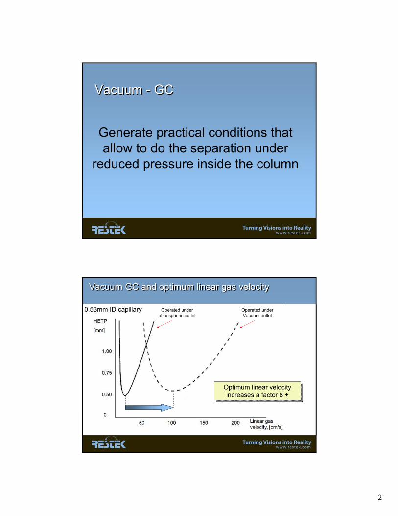
Vacuum - GCVacuum - GC
Generate practical conditions that allow to do the separation under
reduced pressure inside the column
Vacuum GC and optimum linear gas velocityVacuum GC and optimum linear gas velocity
0.53mm ID capillary Operated under atmospheric outlet
Operated under Vacuum outlet
Optimum linear velocity increases a factor 8 +
Optimum linear velocity increases a factor 8 +

3
Why is the analysis faster?Why is the analysis faster?
• Optimal linear velocity of carrier gas increases with applying a higher vacuum
Uopt for helium is 80 -100 cm/s (normal: 15 cm/s)
• Short column length can be usedColumn length is 5 -10 meters of 0.53 mm(Normal MS columns are 25 - 30 m x 0.25 mm)
In total a 10-fold decrease in analysis time is possible..In total a 10-fold decrease in analysis time is possible..
2.5 min30
10 m x 0.53 Metal, 150 °C; 100 kPa He, Column mounted in a MS 10 m x 0.53 Metal, 150 °C; 100 kPa He, Column mounted in a MS
Restriction in the frontRestriction in the back
0
Rt = 29.3 min Rt = 2.55 min
C14 C14
Impact of vacuum on separation using 0.53mm capillary: first experimentImpact of vacuum on separation using 0.53mm capillary: first experiment
Ref: J of HRC &CC 2000, 23, (12), p 677

4
AnalyticalcolumnMass
Spectrometer
GC Oven
Restrictor column
Inlet
Vacuum-GC Instrument Setup -conventional-Restriction in the GC OvenVacuum-GC Instrument Setup -conventional-Restriction in the GC Oven
ll
Alumaseal™Connector
Short (5-10m) wide bore (0.53mm) fused silica capillary column
Short (50-100cm) narrow bore (0.1mm) deactivated fused silica
Make use of advantages of vacuum separation by applying a restriction at the injection side of the system.
Make use of advantages of vacuum separation by applying a restriction at the injection side of the system.
Excerpts from EPA Method 529 (Rev. 1.0)* Illustrating GC-MS Analysis of ExplosivesExcerpts from EPA Excerpts from EPA Method 529 (Rev. 1.0)* Illustrating GC529 (Rev. 1.0)* Illustrating GC--MS Analysis of ExplosivesMS Analysis of Explosives
* * ““Determination of Explosives and Related Compounds in Drinking WaDetermination of Explosives and Related Compounds in Drinking Water by Solid Phase Extraction and Capillary Gas ter by Solid Phase Extraction and Capillary Gas Chromatography/Mass Spectrometry (GC/MS)Chromatography/Mass Spectrometry (GC/MS)””http://www.epa.gov/nerlcwww/m_529.pdfhttp://www.epa.gov/nerlcwww/m_529.pdf

5
Vacuum GC-MS Analysis of Explosives and Explosive Related Compounds : Restriction in the OvenVacuum GC-MS Analysis of Explosives and Explosive Related Compounds : Restriction in the Oven
1
2
34
5
6
7
8
9
10
11 12
1314
15
16
5 μg/mL standard1 μL injection
9. trinitrobenzene10. trinitrotoluene11. PETN12. RDX13. 4-aminodinitrotoluene14. dinitroaniline15. 2-aminodinitrotoluene16. tetryl
1. nitrobenzene2. 2-nitrotoluene3. 3-nitrotoluene4. 4-nitrotoluene5. nitroglycerin6. dinitrobenzene7. 2,6-dinitrotoluene8. 2,4-dinitrotoluene
3.2 minutes: FAST analysis..
Vacuum GC Analysis of Polybromo Diphenyl Ethers:Restriction: 100mm x 0.10mm Vacuum GC Analysis of Polybromo Diphenyl Ethers:Restriction: 100mm x 0.10mm
959879801721644564486
328406
248
m/z
TIC
Oven Temp @ 314°
Conditions (Shimadzu QP2010-Plus)Column: 1m, 0.1mm column connected to a 6m, 0.53mm,
0.25μm Rtx-TNT with an Alumaseal ConnectorInlet: 250 °C, Splitless, 1μL injection volume Col. Flow: 2 mL/min (constant)Oven: 80 °C (hold 1min.) to 320°C @ 20 °C/min (hold 1 min.)Detector: Mass Spec
Ion Source @ 225°C; Interface @ 280°CSolvent cut @ 2.0 min.; SIM Analysis (ions shown below)

6
Vacuum-GC –TOF MS Restriction: 2m x 0.18mm, coated capillaryVacuum-GC –TOF MS Restriction: 2m x 0.18mm, coated capillary
Splitless injection
2m x 0.18mm x 0.2µm Rtx-55m x 0.53mm x 0.25µm Rtx-200
Constant flow He at 2 mL/minFlow velocity column 1: ~200 cm/secFlow velocity column 2: ~120 cm/sec
Oven : 100°C (0.1 min), 60°/min to 350°
BFR Fast ChromatogramBFR Fast Chromatogram
BDE 209 elutes at 3.96 minDBDPE elutes at 4.13 min
BDE 209 elutes at 3.96 minDBDPE elutes at 4.13 min
This separation system only offers +/-10.000 theoretical plates.. Impossible to separate all compounds..
This separation system only offers +/-10.000 theoretical plates.. Impossible to separate all compounds..

7
BFR vacuum GC/TOF Co-elutionsBFR vacuum GC/TOF Co-elutions
BFR – vacuum GC/TOF selective scanning BFR – vacuum GC/TOF selective scanning
8
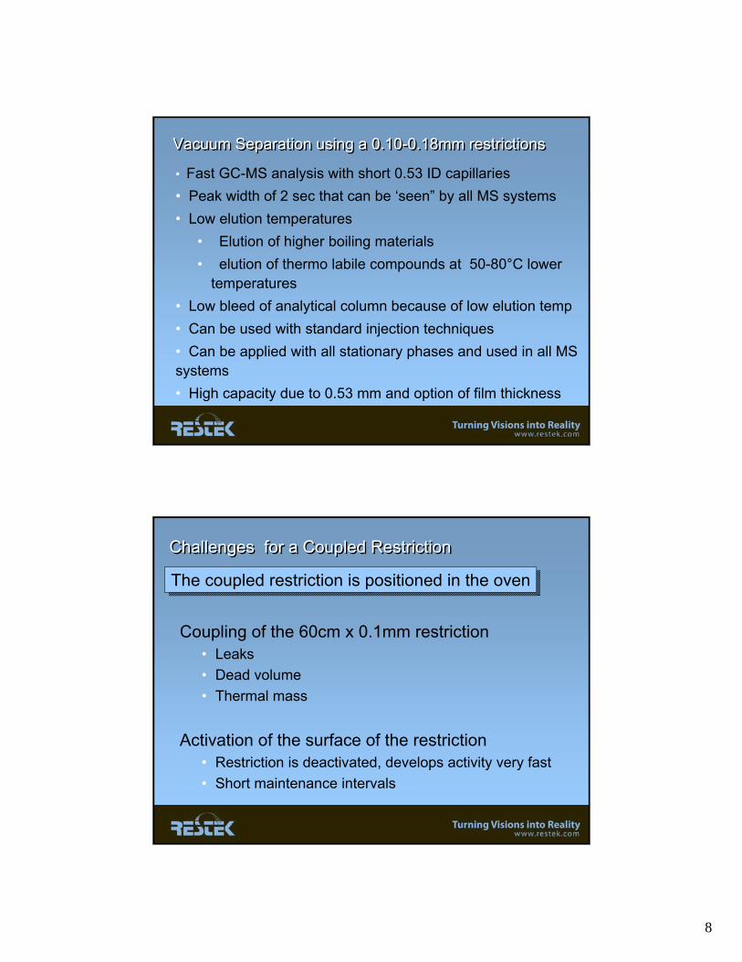
Vacuum Separation using a 0.10-0.18mm restrictionsVacuum Separation using a 0.10-0.18mm restrictions
• Fast GC-MS analysis with short 0.53 ID capillaries • Peak width of 2 sec that can be ‘seen” by all MS systems• Low elution temperatures
• Elution of higher boiling materials• elution of thermo labile compounds at 50-80°C lower
temperatures• Low bleed of analytical column because of low elution temp• Can be used with standard injection techniques• Can be applied with all stationary phases and used in all MS systems• High capacity due to 0.53 mm and option of film thickness
Challenges for a Coupled RestrictionChallenges for a Coupled Restriction
Coupling of the 60cm x 0.1mm restriction• Leaks• Dead volume • Thermal mass
Activation of the surface of the restriction• Restriction is deactivated, develops activity very fast• Short maintenance intervals
The coupled restriction is positioned in the ovenThe coupled restriction is positioned in the oven

9
Alternative SetupAlternative Setup
Press tight-type connector
Restriction
Normal capillary: 0.53 /0.32 /0.25mm ID
Normal liner, 2 – 4 mm ID
This position is the “normal” position for installing a column for split/splitless..
What is the difference?What is the difference?
• Optimal conditions for vacuum GC as restriction length is minimal
• Leaks in coupling are not relevant; also replacement of restriction is easy;
• Good seal: The temperature in the injector will make sure that the seal will be “glued”
• As restriction is in the HOT zone, contamination/activation of restriction will minimally impact separation providing long maintenance intervals..
• Flows in restriction are VERY high, so little contact time..
• All popular injection techniques applicable: split/splitless/PTV.. ( direct?)
• Can be applied with any column dimension: 0.53/0.32 and even 0.25mm, depending what peak width can be dealed with by the MS..
Restriction being in the liner, and is always at high temperature..Restriction being in the liner, and is always at high temperature..

10
Flow in capillary systemsFlow in capillary systems
http://www.explorethecapabilities.com/catalog/3_10.htm
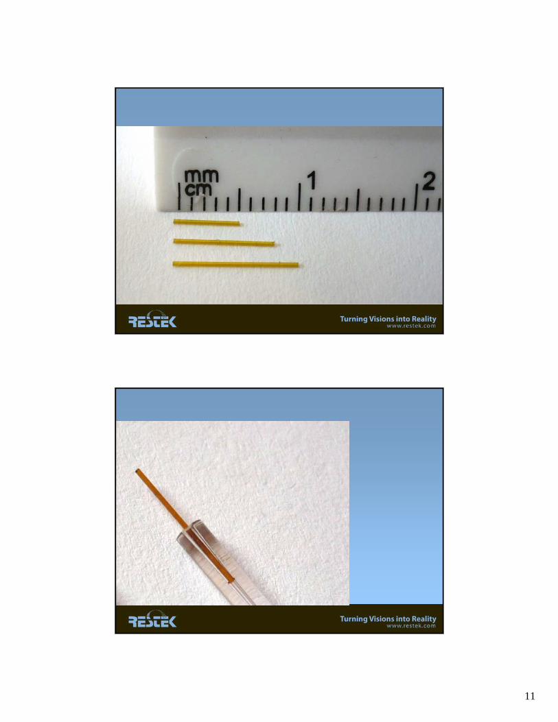
Small ID diameter fused silicaSmall ID diameter fused silica
Materials are commercially available..
Ref: Polymicro Technologies
11
12
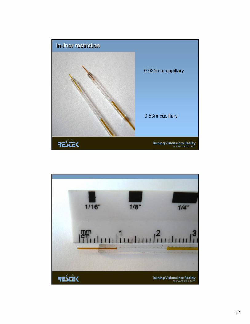
In-liner restrictionIn-liner restriction
0.53m capillary
0.025mm capillary

13
Position of Restriction in linerPosition of Restriction in liner
Patent Pending
Analytical Column10m, 0.53mm, 0.25μmRxi®-5ms (5% diphenyl, 95% dimethylpolysiloxane)
Analytical Column10m, 0.53mm, 0.25μmRxi®-5ms (5% diphenyl, 95% dimethylpolysiloxane)
Mass SpectrometerAgilent 5975
S/SLInlet
0.53mm column insertsdirectly into the MS
GCAgilent 7890
Column nut
Analytical column
Inlet seal
Press-tight
25μm ID tube
Inlet liner
The Experimental SetupRestriction-in-the-Inlet ConceptThe The Experimental SetupSetupRestriction-in-the-Inlet ConceptConcept

14
Test samples usedTest samples used
Mixture of explosives & explosive-related compounds
Concentrations : 5 μg/mL
Solvent : Acetonitrile
The injection/evaporation processThe injection/evaporation process
Split Injection:Fast evaporation, and transfer to analytical column;Similar to pressurized GC
Splitless Injection:
Evaporation and transfer will take more time;
Need a focusing effect
15
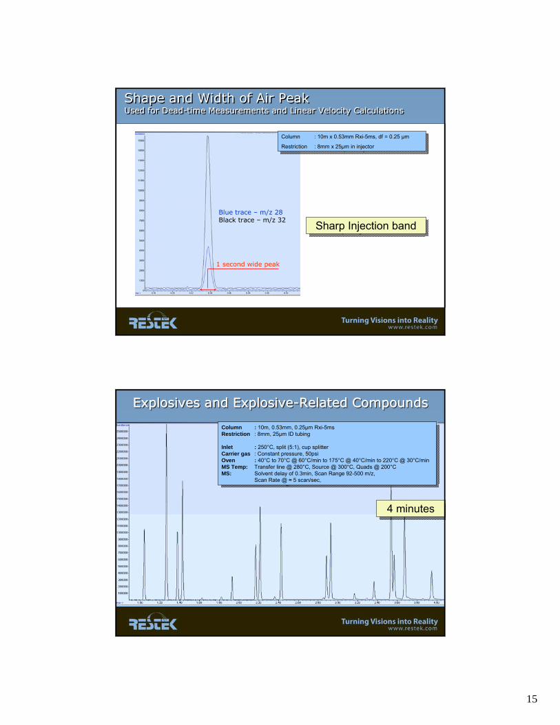
Shape and Width of Air PeakUsed for Dead-time Measurements and Linear Velocity CalculationsShape and Width of Air PeakUsed for Dead-time Measurements and Linear Velocity Calculations
1 second wide peak
Blue trace – m/z 28Black trace – m/z 32
Column : 10m x 0.53mm Rxi-5ms, df = 0.25 μm
Restriction : 8mm x 25μm in injector
Column : 10m x 0.53mm Rxi-5ms, df = 0.25 μm
Restriction : 8mm x 25μm in injector
Sharp Injection bandSharp Injection band
Explosives and Explosive-Related CompoundsExplosives and ExplosiveExplosives and Explosive--Related CompoundsRelated Compounds
Column : 10m, 0.53mm, 0.25μm Rxi-5ms Restriction : 8mm, 25μm ID tubing
Inlet : 250°C, split (5:1), cup splitterCarrier gas : Constant pressure, 50psiOven : 40°C to 70°C @ 60°C/min to 175°C @ 40°C/min to 220°C @ 30°C/minMS Temp: Transfer line @ 280°C, Source @ 300°C, Quads @ 200°CMS: Solvent delay of 0.3min, Scan Range 92-500 m/z,
Scan Rate @ ≈ 5 scan/sec,
4 minutes4 minutes
16
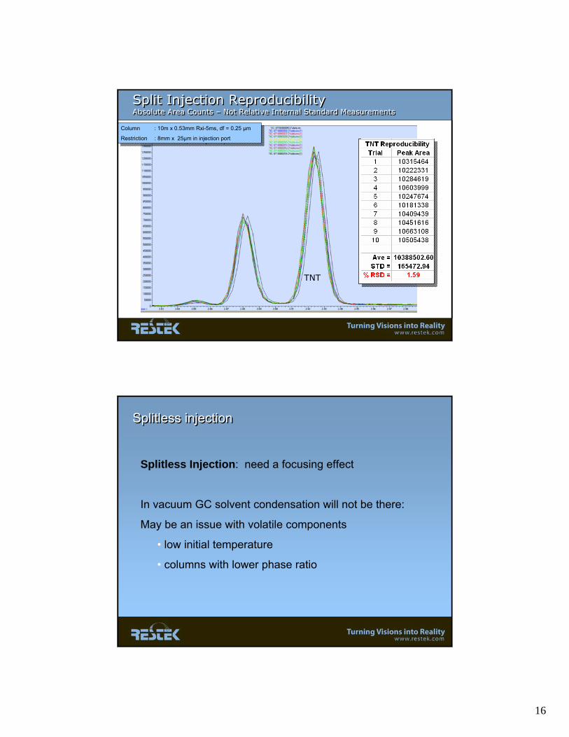
Split Injection Reproducibility Absolute Area Counts – Not Relative Internal Standard MeasurementsSplit Injection Reproducibility Absolute Area Counts – Not Relative Internal Standard Measurements
TNT
Column : 10m x 0.53mm Rxi-5ms, df = 0.25 μm
Restriction : 8mm x 25μm in injection port
Column : 10m x 0.53mm Rxi-5ms, df = 0.25 μm
Restriction : 8mm x 25μm in injection port
Splitless Injection: need a focusing effect
In vacuum GC solvent condensation will not be there:
May be an issue with volatile components
• low initial temperature
• columns with lower phase ratio
Splitless injectionSplitless injection
17
1
2
34
5
6
7
8
9
10
11 12
13
14
15
16
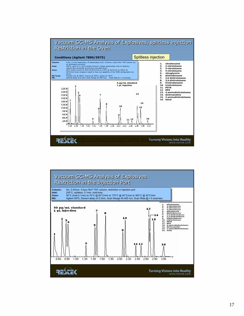
1. nitrobenzene2. 2-nitrotoluene3. 3-nitrotoluene4. 4-nitrotoluene5. nitroglycerin6. dinitrobenzene7. 2,6-dinitrotoluene8. 2,4-dinitrotoluene9. trinitrobenzene10. trinitrotoluene11. PETN12. RDX13. 4-aminodinitrotoluene14. dinitroanaline15. 2-aminodinitrotoluene16. tetryl
Note: HMX in not included in the standard because of suspected role in run-to-run irreproducibility through breakdown and subsequent interference with remaining compounds
Column: 0.5m, 0.1mm Restriction, IP deactivated a 6m, 0.53mm, 0.5μm Rtx®-TNT column via an alumaseal connector
Inlet: 250°C, split (5:1), 4mm Drilled Uniliner® (Siltek deactivated, hole on bottom), column flow nominally at 2mL/min (constant flow)
Oven: 50°C (hold 0.1min) to 70°C @ 60°C/min to 175°C @ 40°C/min to 300°C @ 30°C/min [oven program meant to max out capability of the 7890 configuration we have]
MS Temp: Transfer line @ 280°C, Source @ 250°C, Quads @ 150°CMS: Solvent delay of 0.3min, Scan Range 42-300 m/z, Scan Rate @ ≈ 5 scan/sec,
Conditions (Agilent 7890/5975)
Vacuum GC-MS Analysis of Explosives, splitless injectionRestriction in the OvenVacuum GC-MS Analysis of Explosives, splitless injectionRestriction in the Oven
5 μg/mL standard1 μL injection
Splitless injection
Column: 6m, 0.53mm, 0.5μm Rtx®-TNT column, restriction in injection portInlet: 250°C, splitless, 0.1min. hold-time, Oven: 50°C (hold 0.1min) to 70°C @ 60°C/min to 175°C @ 40°C/min to 300°C @ 30°C/min MS: Agilent 5975, Solvent delay of 0.3min, Scan Range 45-300 m/z, Scan Rate @ ≈ 5 scan/sec,
Column: 6m, 0.53mm, 0.5μm Rtx®-TNT column, restriction in injection portInlet: 250°C, splitless, 0.1min. hold-time, Oven: 50°C (hold 0.1min) to 70°C @ 60°C/min to 175°C @ 40°C/min to 300°C @ 30°C/min MS: Agilent 5975, Solvent delay of 0.3min, Scan Range 45-300 m/z, Scan Rate @ ≈ 5 scan/sec,
Vacuum GC-MS Analysis of Explosives Restriction in the Injection PortVacuum GC-MS Analysis of Explosives Restriction in the Injection Port
18
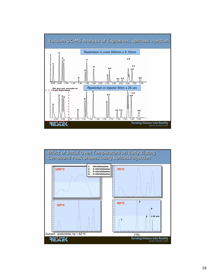
Restriction in oven 500mm x 0.10mm
Restriction in injector 8mm x 25 um
Vacuum GC-MS Analysis of Explosives, splitless injectionVacuum GC-MS Analysis of Explosives, splitless injection
Effect of Initial Oven Temperature on Early Eluting Compound Peak Shapes using Splitless injectionEffect of Initial Oven Temperature on Early Eluting Compound Peak Shapes using Splitless injection
40°C
70°C100°C
1
2
3
4
1.55 min
50°C
1. nitrobenzene2. 2-nitrotoluene3. 3-nitrotoluene4. 4-nitrotoluene
Solvent: acetonitrile, bp = 82 ºC 2 sec

19
Peak width of 2-nitro toluenePeak width of 2-nitro toluene
Starting temperature Base peak width[ºC] [s]
100 xx70 3.350 2.440 2.0
R = 0.996552
2,4,6-TrinitrotolueneTarget ion: 210
R = 0.995568
1,3,5-TrinitrobenzeneTarget ion: 213
1,3,5-TNB
2,4,6-TNT
Calibration Linearity with Vacuum-GC ConditionsCalibration Linearity with Vacuum-GC Conditions
20
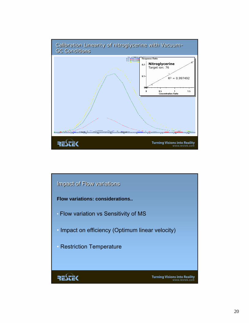
Calibration Linearity of nitroglycerine with Vacuum-GC ConditionsCalibration Linearity of nitroglycerine with Vacuum-GC Conditions
R = 0.997492
NitroglycerineTarget ion: 76
Impact of Flow variationsImpact of Flow variations
Flow variations: considerations..
• Flow variation vs Sensitivity of MS
• Impact on efficiency (Optimum linear velocity)
• Restriction Temperature
21
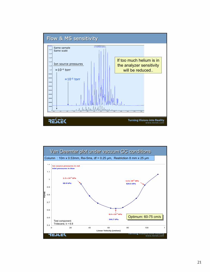
Flow & MS sensitivityFlow & MS sensitivityFlow & MS sensitivity
≈10-5 torr
≈10-4 torr
Ion source pressures
Same sampleSame scale
If too much helium is in the analyzer sensitivity
will be reduced..
0.4
0.5
0.6
0.7
0.8
0.9
1
1.1
1.2
0 20 40 60 80 100 12
Linear Velocity (cm/sec)
H (m
m)
1.3 x 10⁻⁶ kPa
6.6 x 10⁻⁶ kPa
1.4 x 10⁻⁵ kPa
Ion source pressures in redInlet pressures in blue
68.9 kPa
344.7 kPa
620.5 kPa
Test component: Tridecane, k = 6.9
Optimum: 60-75 cm/sOptimum: 60-75 cm/s
Van Deemter plot under vacuum GC conditionsVan Deemter plot under vacuum GC conditionsColumn : 10m x 0.53mm, Rxi-5ms, df = 0.25 μm, Restriction 8 mm x 25 μm

22
Impact of restriction temperatureImpact of restriction temperature
As the restriction is located inside the injection port, the restriction will be subjected to different temperatures
Retention times of explosives were measured by changing the injection port temperature respectively: 200, 250 and 300ºC ;
System in constant pressure mode
At higher temperatures:
• Carrier gas becomes more viscous : flow decreases
• Restriction ID will expand : flow increases
Effect of restriction temperatureEffect of restriction temperature
200ºC
250ºC300ºCAzo-benzene
4.2 sec
4.7 sec

23
6.5 minutes
Environmental Semi-volatile CompoundsEnvironmental Semi-volatile Compounds
Explosives and Explosive-Related CompoundsExplosives and ExplosiveExplosives and Explosive--Related CompoundsRelated Compounds
Column : 10m, 0.53mm, 0.25μm Rxi-5ms Restriction : 8mm, 25μm ID tubing
Inlet : 250°C, split (5:1), cup splitterCarrier gas : Constant pressure, 50psiOven : 40°C to 70°C @ 60°C/min to 175°C @ 40°C/min to 220°C @ 30°C/minMS Temp: Transfer line @ 280°C, Source @ 300°C, Quads @ 200°CMS: Solvent delay of 0.3min, Scan Range 92-500 m/z,
Scan Rate @ ≈ 5 scan/sec,
Column : 10m, 0.53mm, 0.25μm Rxi-5ms Restriction : 8mm, 25μm ID tubing
Inlet : 250°C, split (5:1), cup splitterCarrier gas : Constant pressure, 50psiOven : 40°C to 70°C @ 60°C/min to 175°C @ 40°C/min to 220°C @ 30°C/minMS Temp: Transfer line @ 280°C, Source @ 300°C, Quads @ 200°CMS: Solvent delay of 0.3min, Scan Range 92-500 m/z,
Scan Rate @ ≈ 5 scan/sec,
4 min4 min
nitroglycerine
Tri-nitro Toluene
24
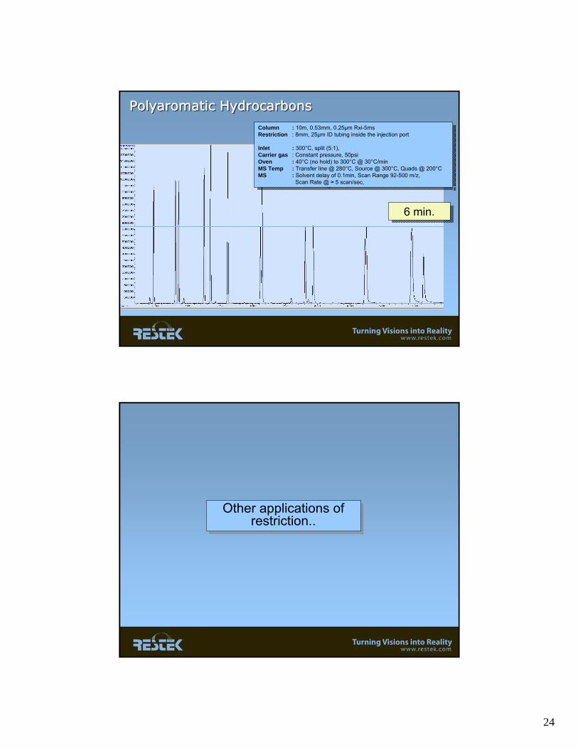
Polyaromatic HydrocarbonsPolyaromaticPolyaromatic HydrocarbonsHydrocarbons
Column : 10m, 0.53mm, 0.25μm Rxi-5ms Restriction : 8mm, 25μm ID tubing inside the injection port
Inlet : 300°C, split (5:1), Carrier gas : Constant pressure, 50psiOven : 40°C (no hold) to 300°C @ 30°C/min MS Temp : Transfer line @ 280°C, Source @ 300°C, Quads @ 200°CMS : Solvent delay of 0.1min, Scan Range 92-500 m/z,
Scan Rate @ ≈ 5 scan/sec,
6 min.6 min.
Other applications of restriction..
Other applications of restriction..

25
Coupling of 0.25, 0.32 and 0.53mm analytical columnsCoupling of 0.25, 0.32 and 0.53mm analytical columns
To use with MS, using short columns of 0.32 /0.25mm..
Non-ms detector applications..
Application of restriction with non-vacuum detectorsApplication of restriction with non-vacuum detectors
Injection volume (gas) will be compressed:• Smaller injection band• Injection of larger volumes
F.I. measurement of impurities in: methane, ethylene, ethane, acetylene, propane, propylene, propadiene, C4 isomers
Injection of gas sample at HIGHER pressure..Injection of gas sample at HIGHER pressure..

26
When using short 0.53mm columns, the digital pressure regulation of many systems is difficult..
.. adding this restriction allows higher pressure setting..
Injection of sample at a HIGHER inlet pressure..Injection of sample at a HIGHER inlet pressure..
Application of restriction with non-vacuum detectorsApplication of restriction with non-vacuum detectors
Restriction alternative setup: double seal applicationRestriction alternative setup: double seal applicationDouble seal on same sideOffers possibility for a Direct semi-on-column injection.. Due to the high velocity and the vacuum, there will be virtually No solvent condensation..
Avoids stress to less stable stationary phases
Cyanopropyl phases in dioxin, furan or FAME
Challenges:• dead volume• release of restriction• blockage
NOTE: this may work also in “non-vacuum” systems

27
Practical setup using a “Uni-Liner”..Practical setup using a “Uni-Liner”..
Vacuum GC of Organochlorine Pesticides: Column & restriction positioned in a “Uniliner”Vacuum GC of Organochlorine Pesticides: Column & restriction positioned in a “Uniliner”
Column : 10m, 0.53mm, 0.25μm Rxi-5ms Restriction : 8mm, 25μm ID tubing inside a drilled uniliner
Inlet : 300°C, 4mm Drilled Uniliner, hole on topCarrier gas : Constant pressure, 50psiOven: 100°C (no hold) to 300°C @ 45°C/min MS Temp: Transfer line @ 280°C, Source @ 300°C, Quads @ 200°CMS: Solvent delay of 0.1min, Scan Range 92-500 m/z,
Scan Rate @ ≈ 5 scan/sec,
3.2 min.3.2 min.
28
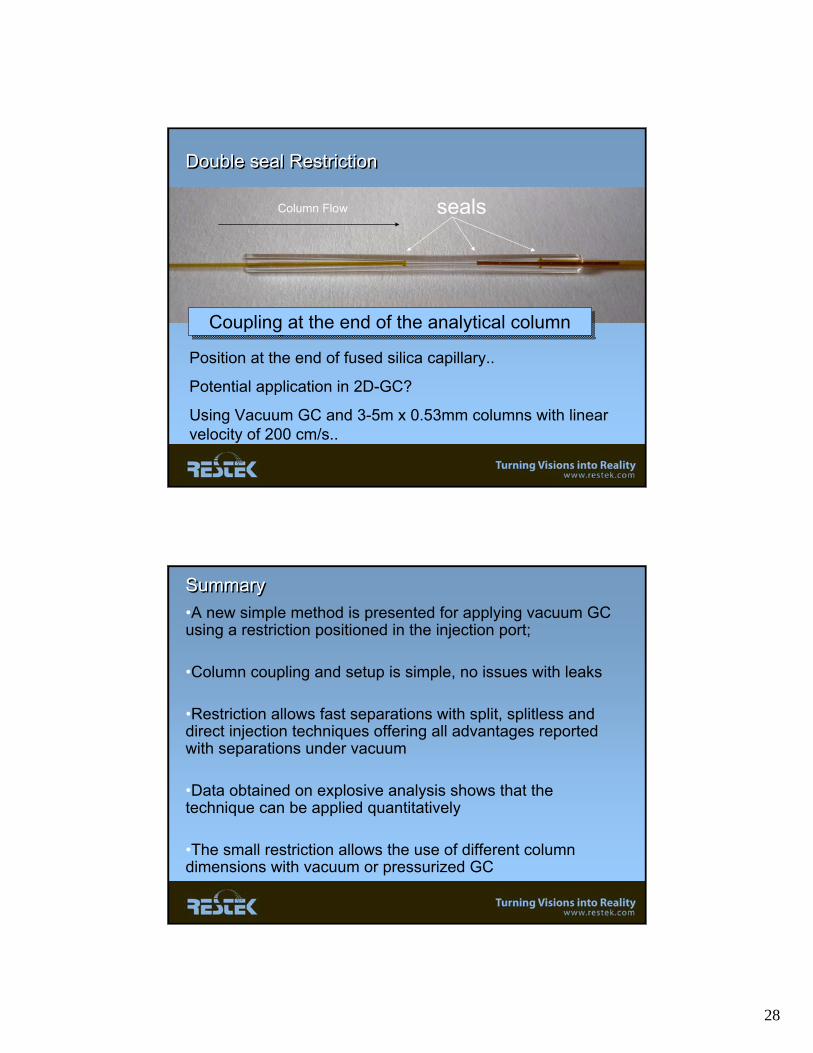
Double seal RestrictionDouble seal Restriction
Position at the end of fused silica capillary..
Potential application in 2D-GC?
Using Vacuum GC and 3-5m x 0.53mm columns with linear velocity of 200 cm/s..
Column Flow seals
Coupling at the end of the analytical columnCoupling at the end of the analytical column
SummarySummary•A new simple method is presented for applying vacuum GC using a restriction positioned in the injection port;
•Column coupling and setup is simple, no issues with leaks
•Restriction allows fast separations with split, splitless and direct injection techniques offering all advantages reported with separations under vacuum
•Data obtained on explosive analysis shows that the technique can be applied quantitatively
•The small restriction allows the use of different column dimensions with vacuum or pressurized GC

29
•With splitless injection, due to vacuum, solvent condensation will be minimal, which requires lower oven starting temperatures..
•Release of septum particles can block restriction
•In order to set the desired flows, the GC control software must be manipulated
•The 25 μm restrictions can also be very helpful in several pressurized GC applications
AcknowledgementsAcknowledgements
• Chris English, Innovations laboratory• Christine Vargo, International sales• Restek Leadership team
• Polymicro Technologies