Embed Size (px)
Citation preview

SIMATIC NET perating Instructions O
SCALANCE W788-1PRO (Access Point)
SCALANCE W788-2PRO (Dual Access Point)
SCALANCE W788-1RR (Access Point iPCF)
SCALANCE W788-2RR Dual Access Point iPCF) (
Preface, Contents
Basic Information on Wireless LAN Communication
1
Description of the SCALANCE W78x 2
Commissioning 3
Configuring the IP Address with the Primary Setup Tool 4
Configuration Using the Wizards of Web Based Management
5
Configuration Using Web Based Management and the Command Line Interface
6
Technical Specifications 7
Approvals, Appendix, Glossary, Index
C79000-G8976-C184-07
Release 10/2006

© Copyright Siemens AG, 1998 to 2006 - All rights reserved The reproduction, transmission or use of this document or its contents isnot permitted without express written authority. Offenders will be liable fo
Classification of Safety-Related Notices
This document contains notices which you should observe to ensure your own personal safety, as well as to protect the product and connected equipment. These notices are highlighted in the manual by a warning triangle and are marked as follows according to the level of danger:
! Danger indicates that death or severe personal injury will result if proper precautions are not taken.
! Warning indicates that death or severe personal injury can result if proper precautions are not taken.
! Caution with warning triangle indicates that minor personal injury can result if proper precautions are not taken.
Caution
without warning triangle indicates that damage to property can result if proper precautions are not taken.
Notice
indicates that an undesirable result or status can occur if the relevant notice is ignored.
Note
highlights important information on the product, using the product, or part of the documentation that is of particular importance and that will be of benefit to the user.
r damages. All rights, including rights created by patent grant or registrationof a utility model or design, are reserved.
Disclaimer We have checked the contents of this manual for agreement with the hardware and software described. Since deviations cannot be precluded entirely, we cannot guarantee full agreement. However, the data in this manual are reviewed regularly and any necessary corrections included in subsequent editions. Suggestions for improvement are welcome.
Siemens AG Automation and Drives Industrial Communication Postfach 4848, D-90327 Nürnberg
C79000-G8976-C184-07 Technical data subject to change.
Siemens Aktiengesellschaft Printed in the Federal Republic of Germany

Operating Instructions SCALANCE W78x 3 C79000-G8976-C184-07
Trademarks
SIMATIC®, SIMATIC NET®, SINEC®, SIMATIC NET Networking for Industry® and SCALANCE® are registered trademarks of Siemens AG.
Third parties using for their own purposes any other names in this document which refer to trademarks might infringe upon the rights of the trademark owners.
Safety Instructions Regarding your Product
Before you use the product described here, read the safety instructions below thoroughly.
Personnel Qualification Requirements
Only qualified personnel should be allowed to install and work on this equipment. Qualified personnel as referred to in this manual or in the warning notes are defined as persons who are familiar with the installation, assembly, startup and operation of this product and who possess the relevant qualifications for their work, e.g.:
Training in or authorization for connecting up, grounding or labeling circuits and devices or systems in accordance with current standards in safety technology
Training in or authorization for the maintenance and use of suitable safety equipment in accordance with current standards in safety technology
First aid qualification
Correct Usage of Hardware Products
Please note the following regarding the correct usage of hardware products:
Caution
This device may only be used for the applications described in the catalog or the technical description, and only in connection with devices or components from other manufacturers which have been approved or recommended by Siemens. This product can only function correctly and safely if it is transported, stored, set up, and installed correctly, and operated and maintained as recommended. Before you use the supplied sample programs or programs you have written yourself, make certain that no injury to persons nor damage to equipment can result in your plant or process.

Prior to Startup
Before putting the product into operation, note the following warning:
Caution
Prior to startup you must observe the instructions in the relevant documentation. For ordering data of the documentation please refer to the catalogs or contact your local SIEMENS representative.
Operating Instructions SCALANCE W78x 4 C79000-G8976-C184-07
Preface
Validity of the Operating Instructions
These Operating Instructions cover the following products:
SCALANCE W788-1PRO
SCALANCE W788-2PRO
SCALANCE W788-1RR
SCALANCE W788-2RR
Where the description applies to all products, the name SCALANCE W78x is used. Where the description applies to a specific product, the full name of the product is used.
These operating instructions apply to the following software versions:
SCALANCE W78x firmware as of Version 3.1
Primary Setup Tool as of Version 3.1
Purpose of the Operating Instructions
These operating instructions are intended to provide you with the information you require to install, commission and operate the SCALANCE W78x correctly. It explains how to configure the SCALANCE W78x and how to integrate the SCALANCE W78x in a WLAN network.
Operating Instructions SCALANCE W78x 5 C79000-G8976-C184-07

Preface
Orientation in the Documentation
Apart from the operating instructions you are currently reading, the following documentation is also available from SIMATIC NET on the topic of Industrial Wireless LANs:
Operating Instructions (compact) SCALANCE W7xx This document is supplied with the device on paper and contains a concise summary of the most important information required to use the following products: SCALANCE W788-1PRO SCALANCE W788-2PRO SCALANCE W788-1RR SCALANCE W788-2RR SCALANCE W744-1PRO SCALANCE W746-1PRO SCALANCE W747-1RR
Operating Instructions SCALANCE W74x The comprehensive documentation for the following products: SCALANCE W744-1PRO SCALANCE W746-1PRO SCALANCE W747-1RR
The document contains all the information for the setup, commissioning and operation of these devices. The SCALANCE W74x is connected to a PC / PLC by an Ethernet cable and allows the attachment of these devices to a wireless network; in other words, it is a gateway from a wired to a wireless network.
System Manual Wireless LAN Basics This includes not only the description of the physical basics and an outline of the most important IEEE standards but also information on data security and a description of industrial uses of wireless LAN. You should read this manual if you want to set up WLAN networks with a more complex structure (not only connections between two devices).
System Manual RCoax This system manual contains both an explanation of the technical basis of leaky feeder cables as well as a description of the SIMATIC NET RCoax components and their functionality. The installation / commissioning and connection of RCoax components is explained.
Manual IWLAN/PB Link PNIO Gateway for Industrial Ethernet The user documentation for the IWLAN/PB Link. This device is a gateway between IWLAN and PROFIBUS.
Operating Instructions CP 7515 The comprehensive user documentation for the CP 7515 communications processor with all the information required to operate this device. The CP 7515 is inserted in a CardBus / PC-card (32-bit) slot and allows attachment of the PC/PG to a wireless network.
Operating Instructions SCALANCE W78x 6 C79000-G8976-C184-07

Preface
Operating Instructions (compact) CP 7515 This document is supplied with the device on paper and contains a concise summary of the most important information required to use the CP 7515.
Manual CP 1515 The comprehensive user documentation for the CP 1515 communications processor with all the information required to operate this device. The CP 1515 is inserted in a PC-card slot (Type II) and allows attachment of the PC/PG to a wireless network.
Operating Instructions SCALANCE W78x 7 C79000-G8976-C184-07

Preface
Biological Compatibility
With regard to the question of whether electromagnetic fields (for example in association with industrial wireless LANs) can put human health at risk, we refer to a publication of BITKOM (German Association for information Technology, Telecommunication and New Media e. V.), dated December 2003:
"The same regulations for the protection of health for all other radio applications also apply to WLAN devices. These regulations are based on the protection concept of ICNIRP2 or the corresponding recommendation of the European Council.
The independent German radiation protection commission (SSK) was commissioned by the federal German ministry of the environment to investigate the possible dangers - thermal and non-thermal - resulting from electromagnetic fields and came to the following conclusions3:
"The SSK comes to the conclusion that even after evaluation of the latest scientific literature, there is no new scientific evidence regarding proven adverse effects on health that causes any doubt regarding the scientific evaluation on which the protection concept of the ICNIRP or the European Council recommendation."
The SSK also concludes that below the current limit values, these is also no scientific suspicion of health risks.
This assessment agrees with those of other national and international scientific commissions and of the WHO (www.who.int/emf).
Accordingly and in view of the fact that WLAN devices are significantly below the scientifically established limit values, there are no health risks from the electromagnetic fields of WLAN products.
2 International Council on Non-Ionizing Radiation Protection 3 'Limit Values and Precautionary Measures to Protect the General Public from Electromagnetic Fields' Recommendation of the Radiation Protection Commission (SSK) with scientific justification, Issue 29, 2001."
You will find further information on this topic under the following URL: www.bitkom.org
Operating Instructions SCALANCE W78x 8 C79000-G8976-C184-07

Contents
1 Basic Information on Wireless LAN Communication ............................................... 13
1.1 Network Structure .............................................................................................. 13 1.2 WLAN Communication ...................................................................................... 19 1.2.1 MAC-based Communication.............................................................................. 19 1.2.2 IP-based Communication .................................................................................. 20
2 Description of the SCALANCE W78x ......................................................................... 21 3 Commissioning............................................................................................................. 31
3.1 Lightning Protection, Power Supply, and Grounding......................................... 31 3.2 Assembly and Connectors................................................................................. 33 3.3 Cabling for Power Supply and Ethernet ............................................................ 35 3.3.1 General Notes.................................................................................................... 35 3.3.2 Assembling an IE Hybrid Cable 2 x 2 + 4 x 0.34 with an IE IP 67 Hybrid
Connector .......................................................................................................... 36 3.3.3 Assembling an IE FC TP Standard Cable 4 x 2 GP or
IE FC TP Flexible Cable 4 x 2 GP with an IE IP 67 Hybrid Connector ............. 40 3.3.4 Pinout of the M12 Connector............................................................................. 43 3.4 Commissioning with the PRESET PLUG .......................................................... 44
4 Configuring the IP Address with the Primary Setup Tool ........................................ 47 4.1 Introduction ........................................................................................................ 47 4.2 Installation of the DLC Protocol in Windows XP Professional........................... 49 4.3 Installation of the DLC Protocol in Windows 2000 Professional SP2................ 50 4.4 Installing the Primary Setup Tool....................................................................... 51 4.5 Working with the Primary Setup Tool ................................................................ 52 4.5.1 Primary Setup Tool via the Command Line....................................................... 56
5 Configuration Using the Wizards of Web Based Management................................ 57 5.1 Introduction ........................................................................................................ 57 5.2 Starting Web Based Management and Logging On.......................................... 59 5.2.1 Connection over HTTPS.................................................................................... 60 5.3 Selecting the Wizards ........................................................................................ 61 5.4 Basic Wizard...................................................................................................... 63 5.4.1 IP Settings ......................................................................................................... 63 5.4.2 System name..................................................................................................... 65 5.4.3 Country Code..................................................................................................... 66 5.4.4 Wireless Settings in Access Point Mode ........................................................... 67 5.4.5 Wireless Settings in Client Mode....................................................................... 68 5.4.6 Adopt MAC Address Settings (Client Mode only).............................................. 69
Operating Instructions SCALANCE W78x 9 C79000-G8976-C184-07

Contents
Operating Instructions SCALANCE W78x 10 C79000-G8976-C184-07
5.4.7 Channel Settings (only in access point mode) .................................................. 72 5.4.8 Finish ................................................................................................................. 74 5.5 Security Wizard.................................................................................................. 75 5.5.1 Security Settings................................................................................................ 76 5.5.2 Security Settings for Management Interfaces ................................................... 77 5.5.3 Security Settings for SNMP Protocol................................................................. 78 5.5.4 Security Settings for WLAN (Page 1, only in access point mode) .................... 79 5.5.5 Security Settings for WLAN (Page 2) ................................................................ 83 5.5.6 Settings for the Security Level Low ................................................................... 87 5.5.7 Settings for the Security Level Medium in Access Point Mode ......................... 88 5.5.8 Settings for Security Level Medium in Client Mode........................................... 89 5.5.9 Settings for the Security Level High .................................................................. 90 5.5.10 Settings for the Security Level Highest.............................................................. 91 5.5.11 The Following Settings Were Made................................................................... 91 5.5.12 Finish ................................................................................................................. 92 5.6 iPCF Wizard....................................................................................................... 93 5.6.1 i Point Coordination Function Settings .............................................................. 93 5.6.2 Security Settings for WLAN ............................................................................... 96 5.6.3 Public Security Key for WLAN ........................................................................... 97 5.6.4 Finish ................................................................................................................. 98
6 Configuration Using Web Based Management and the Command Line Interface 99 6.1 General Information on Web Based Management and the
Command Line Interface ................................................................................... 99 6.1.1 Introduction ........................................................................................................ 99 6.1.2 The LED Simulation of Web Based Management........................................... 100 6.1.3 Working with Web Based Management .......................................................... 101 6.1.4 Command Line Interface (CLI) ........................................................................ 102 6.2 The System Menu............................................................................................ 104 6.2.1 System Information Menu Command.............................................................. 104 6.2.2 IP Settings Menu Command............................................................................ 112 6.2.3 Services Menu Command ............................................................................... 114 6.2.4 Restart Menu Command.................................................................................. 116 6.2.5 Event Config Menu Command ........................................................................ 118 6.2.6 E-mail Config Menu Command ....................................................................... 121 6.2.7 SNMP Config Menu Command ....................................................................... 122 6.2.8 Syslog Menu Command .................................................................................. 127 6.2.9 SNTP Config Menu Command ........................................................................ 130 6.2.10 Fault State Menu Command............................................................................ 131 6.2.11 Load & Save Menu Command ........................................................................ 132 6.2.12 C-PLUG Menu Command................................................................................ 136 6.3 Interfaces Menu ............................................................................................... 141 6.3.1 Ethernet Menu Command ............................................................................... 141 6.3.2 WLAN Menu Command................................................................................... 143

Contents
Operating Instructions SCALANCE W78x 11 C79000-G8976-C184-07
6.3.3 Advanced Submenu ........................................................................................ 149 6.3.4 SSID List Submenu (client mode only)............................................................ 156 6.3.5 Advanced G Submenu..................................................................................... 157 6.3.6 Data Rates Submenu Command (access point mode only) ........................... 160 6.3.7 VAP Submenu Command ............................................................................... 162 6.4 The Security Menu........................................................................................... 163 6.4.1 Basic Wireless Menu Command ..................................................................... 163 6.4.2 Keys Menu Command ..................................................................................... 173 6.4.3 ACL Menu Command ...................................................................................... 174 6.4.4 RADIUS Server Menu Command.................................................................... 178 6.4.5 Access Menu Command.................................................................................. 179 6.5 The Bridge Menu ............................................................................................. 180 6.5.1 WDS Menu Command..................................................................................... 181 6.5.2 VLAN Menu Command.................................................................................... 183 6.5.3 Learning Table Menu Command ..................................................................... 192 6.5.4 ARP Table Menu Command............................................................................ 192 6.5.5 Spanning Tree Menu Command ..................................................................... 192 6.5.6 Storm Threshold Menu Command .................................................................. 202 6.5.7 NAT Menu Command...................................................................................... 203 6.5.8 IP Mapping Table Menu Command................................................................. 208 6.6 The Filters Menu.............................................................................................. 210 6.6.1 MAC Filter Menu Command ............................................................................ 210 6.6.2 MAC Dir Filter Menu Command ...................................................................... 211 6.6.3 Protocol Filter Menu Command....................................................................... 212 6.7 The I-Features Menu ....................................................................................... 213 6.7.1 iQoS Menu Command ..................................................................................... 213 6.7.2 iPCF Menu Command ..................................................................................... 215 6.7.3 Forced Roaming on IP Down .......................................................................... 219 6.7.4 Link Check Menu Command ........................................................................... 220 6.7.5 Redundancy Menu Command......................................................................... 222 6.7.6 IP-Alive Menu Command................................................................................. 224 6.8 The Information Menu...................................................................................... 226 6.8.1 Log Table Menu Command ............................................................................. 227 6.8.2 Auth Log Menu Command............................................................................... 228 6.8.3 Versions Menu Command ............................................................................... 229 6.8.4 Client List Menu Command ............................................................................. 230 6.8.5 Ethernet Menu Command ............................................................................... 232 6.8.6 WLAN Menu Command................................................................................... 232 6.8.7 iQoS Menu Command ..................................................................................... 238 6.8.8 Spanning Tree Menu Command ..................................................................... 240 6.8.9 IP, TCP/IP, ICMP, SNMP Menu Command..................................................... 242 6.8.10 Signal Recorder Menu Command ................................................................... 242
7 Technical Specifications / Approvals....................................................................... 248

Contents
Operating Instructions SCALANCE W78x 12 C79000-G8976-C184-07
Approvals ................................................................................................................................. 252 Appendix .................................................................................................................................. 257
Private MIB Variables of the SCALANCE W78x .......................................................... 257 Designing and Calculating Wireless Systems Based on the Example of RCoax ........ 261 Calculating in Decibels ................................................................................................. 261 Power Specifications .................................................................................................... 262 Losses Based on the Example of a 2.4 GHz RCoax Cable ......................................... 264 Receiver Sensitivity ...................................................................................................... 266 System Calculation Based on the Example of RCoax ................................................. 267
Glossary ................................................................................................................................... 269 Index ...................................................................................................................................... 273

Basic Information on Wireless LAN Communication 11.1 Network Structure
Standalone Configuration with the SCALANCE W78x
This configuration does not require a server and the SCALANCE W78x does not have a connection to a wired Ethernet. Within its transmission range, the SCALANCE W78x forwards data from one WLAN node to another.
The wireless network has a unique name. All the devices exchanging data within this network must be configured with this name.
Figure 1-1 Standalone Configuration of a SCALANCE W78x. The gray area indicates the wireless transmission range of the SCALANCE W78x.
Operating Instructions SCALANCE W78x 13 C79000-G8976-C184-07
Basic Information on Wireless LAN Communication
Operating Instructions SCALANCE W78x 14
d Hoc Networks
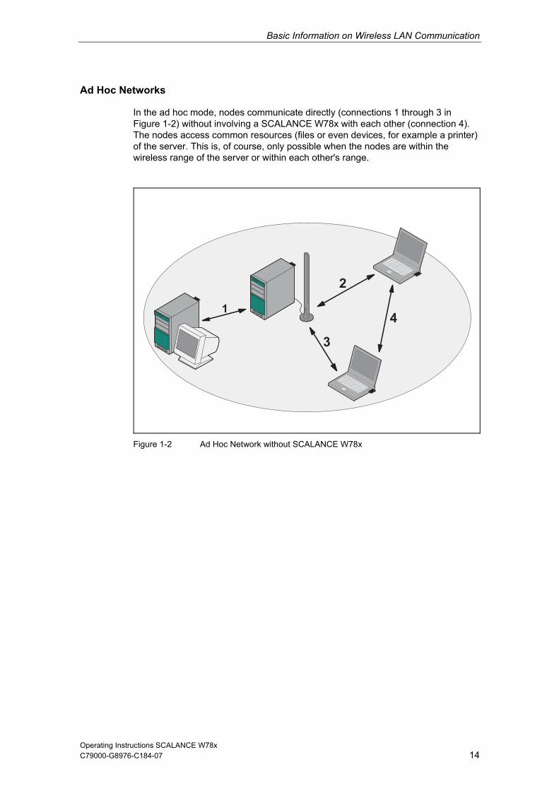
In the ad hoc mode, nodes communicate directly (connections 1 through 3 in Figure 1-2) without involving a SCALANCE W78x with each other (connection 4). The nodes access common resources (files or even devices, for example a printer) of the server. This is, of course, only possible when the nodes are within the wireless range of the server or within each other's range.
A
Figure 1-2 Ad Hoc Network without SCALANCE W
78x
C79000-G8976-C184-07

Basic Information on Wireless LAN Communication
Operating Instructions SCALANCE W78x 15
thernet Network
network can be connected with a wired network over a SCALANCE
ess points are all configured with the same unique SSID (network name). All nodes that want to communicate over this network
ange (cell) of one SCALANCE W78x to the coverage range (cell) of another SCALANCE W78x, the wireless connection is maintained (this is called roaming).
Wireless Access to a Wired E
If one (or more) SCALANCE W78x access points have access to wired Ethernet, the following applications are possible:
A single SCALANCE W78x as gateway: A wireless W78x.
Span of wireless coverage for the wireless network with several SCALANCE W78x access points: The SCALANCE W78x acc
must also be configured with this SSID. If a mobile station moves from the coverage r
Figure 1-3 Wireless Connection of a Mobile Station over two Cells (Roaming)
C79000-G8976-C184-07

Basic Information on Wireless LAN Communication
Operating Instructions SCALANCE W78x 16
nnel,
nd ints
lls.
performance. As a result, neighboring cells each have their own medium and the delays resulting from time-offset transmission no longer occur.
Channel spacing should be as large as possible; a practical value would be 25 MHz. Even in a multichannel configuration, all SCALANCE W78x access points can be configured with the same network name.
Multichannel Configuration
If neighboring SCALANCE W78x access points use the same frequency chathe response times are longer due to the collisions that occur. If the configuration shown in Figure 1-4 is implemented as a single-channel system, computers A aB cannot communicate at the same time with the SCALANCE W78x access poin their ce
If neighboring SCALANCE W78x access points are set up for different frequencies, this leads to a considerable improvement in
Figure 1-4 Multichannel Configuration on Channels 1 and 7 with four SCALANCE W78x Access Points
C79000-G8976-C184-07

Basic Information on Wireless LAN Communication
Operating Instructions SCALANCE W78x 17
)
d to
due to its location.
. The WDS partner can be configured both using its name and its MAC address.
Wireless Distribution System (WDS
WDS allows direct connections between SCALANCE W78x devices and or between SCALANCE W78x and other WDS-compliant devices. These are usecreate a wireless backbone or to connect an individual SCALANCE W78x to anetwork that cannot be connected directly to the cable infrastructure
Two alternative configurations are possible
Figure 1-5 Implementation of WDS with four SCALANCE W78x Access Points
C79000-G8976-C184-07

Basic Information on Wireless LAN Communication
Redundant Wireless LAN (RWlan)
C79000-G8976-C184-07 18
RWlan allows a redundant, wireless connection between two SCALANCE W788--2RR). This is used to set up a redundant
implemented as a wired network due to its location but nevertheless has high demands in terms of availability.
an partner can be configured both using its name and its MAC address.
2xx devices (W788-2PRO or W788wireless backbone that cannot be
Two alternative configurations are possible. The RWl
Figu x.
re 1-6 Implementation of RWlan with two SCALANCE W788-2xAs an alternative, data transfer is possible over one of the two wireless adapters.
Operating Instructions SCALANCE W78x

C79000-G8976-C184-07 19
1.2 W
1.2.1 MA
e MAC
ected to the client over Ethernet is adopted, s
s located downstream from the client cannot be reached. The AP
ess point does not find a match and discards the packets to other nodes.
C nodes downstream from the client: 1
Notes on setting Auto Find Adopt MAC:
he device uses the MAC
f the first received frame.
Note From the moment that the device adopts another MAC address (whether manually or automatically), the device no longer responds to queries of the Primary Setup Tool when the query is received over the WLAN interface. Queries of the PST over the Ethernet interface continue to be replied to.
LAN Communication
C-based Communication
Auto Find Adopt MAC / Adopt MAC manually
Frames in the direction from the client to the access point always have thaddress of the WLAN interface as the source MAC address. As a result, the learning table at the access point end always has only the MAC address of the WLAN interface of the client.
If the MAC address of a device connboth the MAC-based and the IP-based frames find their destination in precisely thidevice.
Other nodechecks whether the destination MAC matches the MAC addresses of the connected clients. Since a client can only adopt one MAC address, the acc
Maximum possible number of MA
As long as there is no link on the Ethernet interface, taddress of the Ethernet interface so that it can be reached in this status. In thisstatus, the device can be found using the Primary Setup Tool.
As soon as there is a link on the Ethernet interface, the device adopts the source MAC address o
Adopt Own MAC (only W746/W747 and W788 in client mode)
If IP-based frames need to be sent to a device connected downstream from the client, the default setting Adopt Own Mac can be retained. The client registers with the MAC address of its Ethernet adapter. The IP packets are broken down according to an internal table and forwarded to the connected devices (IP mapping).
Operating Instructions SCALANCE W78x

Basic Information on Wireless LAN Communication
C79000-G8976-C184-07 20
Communication at the MAC address level (ISO/OSI layer 2) is then only possible with a component downstream from the client if its MAC address was adopted by the client.
client: 0
Layer 2 Tunneling (only W746/W747 and W788 in client mode)
With layer 2 tunneling, the client provides information about the devices downstream from it when it registers with an access point. This makes it possible to enter the MAC addresses of these devices in the learning table of the access point. The access point can forward MAC-based frames for the devices downstream from
priate client.
e L2T client
ber of MAC nodes downstream from the client: 8
1.2.2 IP-based Communication
IP Mapping
osev With IP mapping, the client maintains a table with
s to
Maximum possible number of IP nodes downstream from the client: 8
Maximum possible number of MAC nodes downstream from the
the client to the appro
In much the same way as with WDS, a separate port is created for thover which the Ethernet frames are sent without changing the destination MAC address.
Maximum possible num
(only W746/747 and W788 in client mode)
If there is more than one device connected downstream from the client and these sh uld only be addressed with IP frames, you can implement WLAN access for
eral devices with one client.the assignment of MAC address and IP address to forward incoming IP framethe correct MAC address.
Operating Instructions SCALANCE W78x

C79000-G8976-C184-07 21
Description of the SCALANCE W78x
Componen o
The ponents are supplied with the SCALANCE W78x:
1 IE IP 67 hybrid plug-in connection
1 protective cap for the M12 socket
2 (or 4 with SCALANCE W788-2PRO or SCALANCE W788-2RR) protective caps for the R-SMA sockets
1 SIMATIC NET Industrial Wireless LAN CD with these Operating Instructions for the SCALANCE W78x
Please check that the consignment you have received is complete. If it is not complete, please contact your supplier or your local Siemens office.
Requirements for Installation and Operation
A PG/PC with a network attachment must be available to configure the SCALANCE W78x. If no DHCP server is available, a PC on which the Primary Setup Tool (PST) is installed is necessary for the initial assignment of an IP address to the SCALANCE W78x. For the other configuration settings, a computer with Telnet or an Internet browser is necessary.
2
ts f the Product
following com
SCALANCE W78x
2 OMNI antennas
Operating Instructions SCALANCE W78x

Description of the SCALANCE W78x
Operating Instructions SCALANCE W78x 22
NCE W78x
inte 88-2RR: two WLAN
one
The SCALANCE W78x can be used as a wireless bridge between two tworks.
O ireless link can also be
implemented between two SCALANCE W788-2xx modules.
C79000-G8976-C184-07
Possible Applications of the SCALA
The SCALANCE W78x is equipped with an Ethernet interface and a wireless LANrface (SCALANCE W788-2PRO and SCALANCE W7
interfaces). This makes the device suitable for the following applications:
The SCALANCE W78x forwards data within its transmission range fromnode to another without a connection to wired Ethernet being necessary.
The SCALANCE W78x can be used as a gateway from a wired to a wireless network.
ne
The SCALANCE W78x can be used as a bridge between two different frequencies.
Over and above this, due to the second interface of the SCALANCE W788-2PRand the SCALANCE W788-2RR, a redundant w

Description of the SCALANCE W78x
Operating Instructions SCALANCE W78x 23
roperties SCALANCE W78x
Operating the wireless interface in the frequency bands 2.4 GHz and 5 GHz.
e wireless interface is compatible with the standards IEEE 802.11a ,
gross transmission rate is up to 54 Mbps. In turbo mode, the Transmission rate
N
If NCE ate (A rbo), remember that the channels o the set transmission channel are also used for communic rb n therefo on these channels when there are neighboring wireless systems. The da hput can also be reduced if there is com etition for use these hannel
C79000-G8976-C184-07
P of the
The Ethernet interface supports 10 Mbps and 100 Mbps, both in full and half duplex as well as autocrossing and autonegotiation.
ThIEEE 802.11b and IEEE 802.11g. In the 802.11a- and 802.11g mode, the
is up to 108 Mbps (not permitted in all countries and modes).
ote the SCALA W78x is oper
adjacent td in turbo mode , G or H tu
ation. Distu ances ca re occur ta throug
p of c s.
As an expansion of the 802.11a mode, it is also possible to op g to the IEEE 802.11h standard. In 802.11h mode, the procedures Transmit
r Control (TPC) a Dynamic Freq cy Selectio (DFS the range 5.25 - 5.35 and 5.47 - 5.75 GHz. This means that in som the frequency sub-band 5.47 - 5.725 GHz can also be used outdo er transmit power.
C is a method of co ling the transmit power tha reduurrently required level. With dynamic fre ency selec n (DF
point searches for primary users (for example radar) on a rand cted channel before starting communication. If signals are found on
annel is disabled and the availability check is repeated on nothe hannel.
The gross transmission rate is up to 54 Mbps in 802.11h mod
Support of the authentication standards WPA, WPA-PSK, WP
inclusion of a RADIUS server for authentication.
ices with Wi-Fi devices of other vendors was tested thoroughly.
Only for W78x-1RR/2RR: The iPCF mode provides an optimized data throughput and minimum handover times.
erated accordin
Powe nd uen n ) are used ine countries,
ors with high
TPc
ntrol t is tio
ced to the S), the access quomly sele the channel,
this cha
for 30 minutes r c
e.
A2, WPA2-PSKand IEEE 802.1x and the encryption methods WEP, AES and TKIP.
Suitable for
Device-related and application-related monitoring of the wireless connection.
The interoperability of SCALANCE W78x dev

Description of the SCALANCE W78x
Operating Instructions SCALANCE W78x 24
Note 788-xRR as SCALANCE W747-
W746-1PRO.
C79000-G8976-C184-07
In the client mode, you can use a SCALANCE W1RR and a SCALANCE W788-xPRO as SCALANCE
Not
For that you enable the iPCF mode. e PNIO communication, we always recommend
The following table illustrates the differences between the various variants of theSCALANCE W78x:
Type No. of WLAN interfaces
No. of supported IP nodes (3)
No. of supported MAC nodes (3)
iPCF mode (1)
Order no.
1 2 1 several 1 several
W788-1PRO
6GK5788-1ST00-2AA6 6GK5788-1ST00-2AB6 (2)
W788-2PRO
6GK5788-2ST00-2AA6 6GK5788-2ST00-2AB6 (2)
W788-1RR 88-
6GK5788-1SR00-2AB6 (2)
6GK571SR00-2AA6
W788-2RR 6GK5788-2SR00-2AA6
-2SR00-2AB6 (2)
6GK5788
(1) The iPCF rovides an ut and minimum handover times. (2) US varia(3) In client mode.
In the SCALANCE HELPconfigurat o
mode pnt
optimized data throughp
W78x ion parameters
function, you will find further informf the relevant device.
ation on the

Description of the SCALANCE W78x
Operating Instructions SCALANCE W78x 25
Ports
The SCAL 78x ha
RJ-45 cto isting of an RJ-45 jack an we s the use of switches capable of power-over-Ethernet according to 802.3af. The 4-pin power socket allows power of 18 - 32 V DC.
s optio
Two R-SMA plugs (fou PRO and SCALANCE W788-2R chment of antennas on the sides of the device.
LED Display
On the front of the housing g status of the SCALANCE W
ANCE W s the following ports:
hybrid conned 4-pin po
r on the front panel of the housing consr socket. The RJ-45 connector support
An M12 connector a nal power supply (18 - 3
r R-SMA plugs on the SCALANCE W788-2
2 V DC).
R) for the atta
, several LEDs provide information on the operatin78x:
Figure 2-1 The LEDs of the SCALANCE W78x
C79000-G8976-C184-07

Description of the SCALANCE W78x
Operating Instructions SCALANCE W78x 26
nce:
C79000-G8976-C184-07
The LEDs have the following significa
LED Color Meaning
Yellow Data transfer over the Ethernet interface (traffic).
Green There is a connection over the Ethernet interface. (Link)
Yellow flashing PRESET-PLUG detected.
Yellow/green PRESET function completed successfully.
P1
Green flashing "Flashing“ enabled over PST.
L2 Green Power supply over the hybrid connector X1 (PoE or energy contacts).
Yellow Data transfer over the first WLAN interface.
Green Access Point Mode:
There is a connection over the first WLAN interface.
The WLAN interface is initialized and ready for operation. Client Mode:
Green flashing Access Point Mode: The channels are scanned. Client Mode: The client is searching for a connection to an access point or ad hoc network.
Green flashing quickly
Access PointWith 802.11h
Mode: the channel is scanned for one minute for
.
ess due to the setting o Find Adopt MAC> and is connected to no access point.
primary users before the channel can be used for data trafficClient Mode: The client waits for the adopt MAC addr<Aut
Yellow flashing PRESET-PLUG detected.
Green Clie3x fast,
flashing
nt Mode: MAC address due to the setting
nd is connected to an access point. 1x long The client waits for the adopt <Auto Find Adopt MAC> a
R1
Yellow/green PRESET function completed successfully.
LED Color Meaning
Yellow Access Point Mode: Data transfer over the second WLAN interface. Client Mode: The LED is always off because the 2nd interface is not available in client mode.
Green Access Point Mode: The WLAN interface is initialized and ready for operation.
ways off because the 2nd interface is not available in client mode.
Client Mode: The LED is al
R2
Green flashing Access Point Mode: The channels are scanned. Client Mode: The LED is always off because the 2nd interface is not available in client mode.

Description of the SCALANCE W78x
Operating Instructions SCALANCE W78x 27
ED Color Meaning
C79000-G8976-C184-07
L
Green flashing quickly
Access Point Mode: With 802.11h the channel is scanned for one minute for primary users before the channel can be used for data traffic.
nt Mode: e LED is always off because the 2nd interface is not
ClieThavailable in client mode.
Yellow flashing PRESET-PLUG detected.
Yellow/green PRESET function completed successfully.
L1 Green Power supply over the M12 connector (X2).
F ation with the SCALANCE W78x.
Red An error occurred during oper
Not
If thit is ac t ready for operation (interface not initialized). ThSCAL iting time of up to 15 minutes can occur when the ambient temperature is below zero. The device is ready for operation at the spegreen
e e LED for the WLAN interface is not green when the device starts up, although
tivated, the interface is noe main reason for this is usually that during commissioning of the
ANCE W78x products, a wa
cified ambient temperature as soon as the LED for the WLAN interface is lit .

Description of the SCALANCE W78x
Operating Instructions SCALANCE W78x 28
Configuration Information on the C-PLUG
The dev rts up with the C-PLUG, it then continues automatically with exactly the same configuration as the old device. One exception to this can be the IP configuration if it is set over DHCP and the DHCP server has not been reconfigured accordingly.
Reconfiguration is necessary if you use WDS or redundancy and use the MAC addresses and not the sysNames. These functions are then based on the MAC address that inevitably changes if a device is replaced.
Note As soon as the device is started with a C-PLUG inserted, the SCALANCE W starts up with the configuration data on the C-PLUG.
C79000-G8976-C184-07
C-PLUG is used to transfer the configuration of the old device to the newice when a device is replaced. When the new device sta
Replacing the C-PLUG
Follow the steps below to replace a C-PLUG in a SCALANCE W78x:
1 Turn off the power to the device.
2 Remove the old SCALANCE W78x from its mounting and open the sealing screw on the rear with a coin or broad screwdriver.
3 Remove the C-PLUG.
4 Open the sealing screw of the new device in the same way and insert the C-PLUG of the old device.
5 Replace the sealing screws of both devices.
If a new C-PLUG is inserted in a SCALANCE W78x, the configuration stored locally on the SCALANCE W78x is saved to the C-PLUG. If an incorrect C-PLUG (for example from another device or a damaged plug) is inserted, the SCALANCE W78x signals an error with the red LED. The user then has the choice of either removing the C-PLUG again or selecting the option to reformat the C-PLUG and use it.
Note
It is necessary that the configuration on the C-PLUG was generated with a firmware version ≤ the firmware version on the destination device. Example: A C-PLUG with version V3.0 cannot be used for a SCALANCE W78x with firmware version V2.4.

Description of the SCALANCE W78x
Operating Instructions SCALANCE W78x 29
eset Button
The reset button is on the rear of the device directly beside the C-PLUG receptacle and has several functions:
ice. , press the Reset button.
Loading new firmware (Only if the normal procedure for loading firmware with Load & Save (see Section. 6.2.10) does not work). This can, for example, occur if there was a
Follow the steps below to load new firmware:
r to the device.
2. Now press the Reset button and reconnect the power to the device while ing down the button.
5. Assign an IP address with the Primary Setup Tool.
mmand "ftp <ip address>“ in a DOS box or use a different der as the
8. For the login and password, enter "siemens“. You can now transfer the new ware with the "put <firmware>“ command.
Caution:
C79000-G8976-C184-07
R
Restarting the devTo restart the device
power down during the normal firmware update.
1. Turn off the powe
hold
3. Hold down the button until the red fault LED (F) starts to flash after approximately 2 seconds.
4. Now release the button. The bootloader waits in this state for a new firmware file that you can download by FTP.
6. Connect a PC to the SCALANCE W78x over the Ethernet interface.
7. Then enter the coFTP client. The new firmware should be located in the same folDOS box.
firm
9. Once the firmware has been transferred completely to the device, the deviceis restarted automatically.
Restoring the default parameters (factory default) All previously made settings are lost!
First, turn off the power to the device. Now press the Reset button and reconnect the power to the device while holding down the button. Hold down
button until the red fault LED (F) stops flashing after approximately 10
theseconds and is permanently lit. Now release the button and wait until the fault LED (F) goes off again. The device then starts automatically with thedefault parameters.

Description of the SCALANCE W78x
Operating Instructions SCALANCE W78x 30
Adopting the configuration data from the PRESET PLUG. evice restarts with a valid PRESET PLUG, by pressing the button
C79000-G8976-C184-07
If the dbriefly, the configuration data is adopted by the device.

Commissioning
Operating Instructions SCALANCE W78x 31
Com 33.1 Ligh
Notes on Lightning Protection
missioning
tning Protection, Power Supply, and Grounding
C79000-G8976-C184-07
! Warning Antennas installed outdoors must be within the area covered by a lightning protection system. Make sure that all conducting systems entering from outdoors can be protected by a lightning protection potential equalization system. When implementing your lightning protection concept, make sure you adhere to the
r IEC 62305 standard. VDE 0182 o
A suitable lightning conductor is available in the range of accessories of SINET Industrial WLAN:
Lightning Protector LP798-1
MATIC
PRO (order no. 6GK5798-1LP00-0AA6)
! Warning Installing this lightning protector between an antenna and a SCALANCE W788 is not adequate protection against a lightning strike. The LP798-1PRO lightening protector only works within the framework of a comprehensive lightning protection concept. If you have questions, ask a qualified specialist company.
r: DEHN+SÖHNE GmbH+Co.KG Hans Dehn Str.1 Postfach 1640 D-2306 Neumarkt, Germany
Note The requirements of EN61000-4-5, surge test on power supply lines are met only when a Blitzductor VT AD 24V type no. 918 402 is used Manufacture9

Description of the SCALANCE W78x
Operating Instructions SCALANCE W78x 32
Safety extra-low voltage (SELV)
! Warning The SCALANCE W78x devices are designed for operation with safety extra-low voltage (SELV). Therefore only safety extra-low voltage (SELV) with limited power source (LPS) complying with IEC950/EN60950/VDE0805 may be connected to the power supply terminals. The power supply unit to supply the SCALANCE W78x must comply with NEC Class 2 (voltage range 18 - 32 V, current requirement 1 A) The device may only be supplied by a power supply unit that meets the requirements of class 2 power sources of the "National Electrical Code, table 11
)". If the power supply is designed redundantly (two separate power supplies), ust meet these requirements.
LV (according to VDE 0100-410) is also possible if the generated rated voltage does not exceed the voltage limits 25 V AC or 60 V DC.
• Power supply by a SELV power source (according to IEC 60950) or PELV power source (according to VDE 0100-410) without limited power is also permitted if suitable fire protection measures are taken by:
- Installation in a cabinet or suitable enclosure - Installation is a suitably equipped, closed room
(bboth mExceptions: • Power supply with PE
Grounding
Caution There must be no potential difference between the following parts otherwise there is a risk that the device will be destroyed: • Ground potential of the power supply and ground potential of the antenna
ground. • Ground potential of the power supply and a grounded housing. • Ground potential of the power supply and the ground potential of the device
connected to Industrial Ethernet (for example PC, AS-300, AS-400 etc.) Connect both grounds to the same foundation earth or use an equipotential bonding cable.
Power over Ethernet
Connecting several SCALANCE W7xx devices with PoE supply from a common PoE switch (acting as power supply) is not possible.
C79000-G8976-C184-07

Description of the SCALANCE W78x
Operating Instructions SCALANCE W78x 33
There are two ways of securing the housing:
e the holes in the housing to screw the device to the wall or on a horizontal surface.
se, the standard rail serves as an adapter stall the SCALANCE
cting cable.
tWe recommeshof bling. When operating the SCALANCE W outdoors, make sure
exposed r
C79000-G8976-C184-07
3.2 Assembly and Connectors
Securing the Housing
Us
Install the SCALANCE W78x on a 90 mm long, vertically mounted piece of standard rail (S7-300). In this cabetween the wall and SCALANCE W78x. If you want to inW78x along with a PS791-1PRO, a 150 mm long standard rail is necessary.
Make sure that there is suitable strain relief for the conne
No e nd that you protect the device from direct sunlight with a suitable
ade. This avoids unwanted heating of the device and prevents premature ageing the device and ca
that it is installed so that it is protected from UV and that the device is not to ain (installed under a roof).
The minimum distance to fluorescent lamps should be 0.5 m. For cabinet Note
installation, we recommend that you do not install relays on the same or on directly neighboring mounting rails.
Connectors for the Power Supply and for Ethernet
The SCALANCE W78x is attached to Ethernet via a hybrid socket on the front of the housing (position A in Figure 3.1). This port also has contacts for the operating voltage.
Note
If you do not use the hybrid socket, this must be covered with a protective cap, otherwise IP 65 protection is lost. A suitable protective cap is available as an accessory (order no. 6ES7194-1JB10-0XA0). If you do not use the M12 connector, the supplied protective cap must also be fitted to retain the IP65 degree of protection.

Description of the SCALANCE W78x
Operating Instructions SCALANCE W78x 34 C79000-G8976-C184-07
Figure 3-1 Connectors of the SCAL
As an alternative or in addition to this, u er supply (position B in Figure 3.1).
You can fit additional antennas to the SCALANCE W788-2RR with an anten C in Figure 3.1). If you install the SCALANCE W78x in a cabmust be unscrewed due to the restricconnection is over detached antennapanel, there is also an identifier for thon the right-hand side and B connect
SIMATIC NET offers the IWLAN FRNC antenna extension cable for the connection between the SCALANCE W78x and detached antenna. To avoid violating the approvals, only antennas released for this product can be used.
Note T a pair of antennas for the first and sem
ANCE W78x
yo can also use the M12 plug for the pow
sides of the SCALANCE W788-2PRO and na cable (position
inet, the antenna (position D in Figure 3.1) ted communication. In this case, the s in store outside the cabinet. On the front e antenna connectors. The A connectors are ors B on the left-hand side.
he distance betweenust be at least 0.5 m.
cond WLAN interface
Description of the SCALANCE W78x
Operating Instructions SCALANCE W78x 35
3.3 Cabling for Power Supply a
3.3.1 General Notes
Suitable Cables
The following cable variants are available to connect a SCALANCE W78x to the power supply and to Ethernet:
IE hybrid cable 2 x 2 + 4 x 0.34 (o
The two data wire pairs are separasuitable for assembly with the IE IP 67 hybrid co
IE FC TP standard cable 4 x 2 GPIE FC TP flexible cable 4 x 2 GP ( -2H)
In these cable types, two wires are twisted. All four pairs of wires are inside a common shield.
2 x 2 IE cable, the optional power supply (18 - 32 V DC) is over M12 connectors.
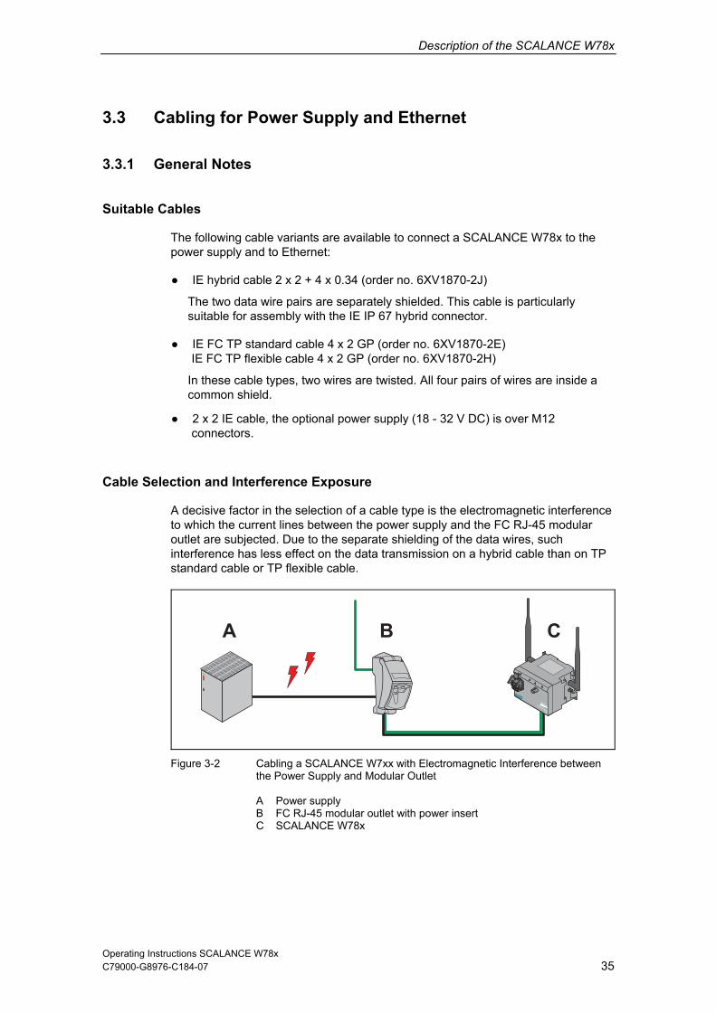
Cable Selection and Interference Exposure
A decisive factor in the selection of a e to which the current lines between the dular outlet are subjected. Due to the separinterference has less effect on the datstandard cable or TP flexible cable.
nd Ethernet
rder no. 6XV1870-2J)
tely shielded. This cable is particularly nnector.
(order no. 6XV1870-2E) order no. 6XV1870
cable type is the electromagnetic interferenc power supply and the FC RJ-45 moate shielding of the data wires, such a transmission on a hybrid cable than on TP
Figure 3-2 Cabling a SCALANCE W Interference between
the Power Supply and M A Power supply B FC RJ-45 modular outlet with power insert C SCALANCE W78x
7xx with Electromagneticodular Outlet
C79000-G8976-C184-07

Description of the SCALANCE W78x
Operating Instructions SCALANCE W78x 36
3.3.2 Assembling an IE Hybrid Cable Hybrid Connector
2 x 2 + 4 x 0.34 with an IE IP 67
Remove the two inner shells of the universal sealing ring to adapt it to the diameter of the hybrid cable.
Push the bushing, washer, adapted universal sealing ring and the housing over the cable jacket.
Remove the following lengths of ble jacket and shield braid:
ds. s
m).
ca• 25 mm for the power lea• 30 mm jacket for the data lead
(shorten the braid by 11 mCut off the filler at the height of the cable jacket.
Arrange the data leads according to the color codes on the splice
hows element. The following table sthe assignment of the data leads.
Contact and color assignment of the splice element.
C79000-G8976-C184-07

Description of the SCALANCE W78x
Operating Instructions SCALANCE W78x 37
Wire color code (standard) White Blue Yellow Orange
Connector color code (Siemens IE) White Blue Yellow Orange
Siemens IE FC RJ-45 socket (reference)
3 6 1 2
Insert the all the data leads at the same time into the splice element is far as they will go.
Cl se the splice element o and RJ-45 data module until they lock together.
Insert the data module and the splice element into the supplied IDC assembly tool.
Press the data module and the IDC assembly tool together to establish the installation piercing connection.
C79000-G8976-C184-07

Description of the SCALANCE W78x
Operating Instructions SCALANCE W78x 38
Remove the assembled data module from the IDC assembly tool.
Position the top shield plate and press it over the cable shield.
Position the lower shield plate and press it and the upper shield plate together until they lock together with an audible "click".
Arrange the power leads and insert them as far as they will go into the hinge elements of the isolation body.The following table shows the assignment of the power leads.
Wire color code (standard) Brown Brown Black Black
24 V 24 V Ground Ground
Power supply insert module 1 2 3 4
C79000-G8976-C184-07

Description of the SCALANCE W78x
Operating Instructions SCALANCE W78x 39
Press each individual hinge element together with the integrated IDC contact. Recommendation: Use a smallslotted screwdriver (max. 3.5 mmas a lever.
)
Push the housing over the assembled data module and the
ulator body until they lock together (there should be an audible click).
ins
Tighten the cable gland. We recommend an open ring key with a size of 21 mm.
C79000-G8976-C184-07
Description of the SCALANCE W78x
Operating Instructions SCALANCE W78x 40
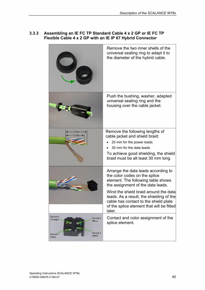
3.3.3 Assembling an IE FC TP Standard Cable 4 x 2 GP or IE FC TP Flexible Cable 4 x 2 GP with an IE IP 67 Hybrid Connector
Remove the two inner shells of the universal sealing ring to adapt it to the diameter of the hybrid cable.
Push the bushing, washer, adapted universal sealing ring and the housing over the cable jacket.
Remove the following lengths of cable jacket and shield braid: • 25 mm for the power leads. • 30 mm for the data leads.
To achieve good shielding, the shield braid must be alt least 30 mm long.
Arrange the data leads according to the color codes on the splice element. The following table shows the assignment of the data leads. Wind the shield braid around the data leads. As a result, the shielding of the cable has contact to the shield plate of the splice element that will be fitted later.
Contact and color assignment of the splice element.
C79000-G8976-C184-07

Description of the SCALANCE W78x
Operating Instructions SCALANCE W78x 41
Standard Cable
C79000-G8976-C184-07
Color Coding of the White / Orange *
Orange
White / Green *
Green
Connector color code (Siemens IE)
White
Blue
Yellow
Orange
Siemens IE FC RJ-45 socket (reference) 3 6 1 2
* White wire of the particular pair.
Insert the all the data leads at the same time into the splice element is far as they will go.
Close the splice element and RJ-45 data module until they lock together.
Insert the data module and the splice element into the supplied IDC assembly tool.
Press the data module and the IDC assembly tool together to establish the installation piercing connection.

Description of the SCALANCE W78x
Operating Instructions SCALANCE W78x 42
Remove the assembled data module from the IDC assembly tool.
Position the top shield plate and press it over the cable shield.
Position the lower shield plate and press it and the upper shield plate together until they lock together with an audible "click".
Arrange the power leads and insert them as far as they will go into the hinge elements of the isolation body.The following table shows the assignment of the power leads.
Wire color code (standard)
White / Blue *
Blue
White brown *
Brown
24 V 24 V Ground Ground
Power supply insert module 1 2 3 4
* White wire of the particular pair.
C79000-G8976-C184-07

Description of the SCALANCE W78x
Operating Instructions SCALANCE W78x 43
Press each individual hinge element
mmendation: Use a small
together with the integrated IDC contact. Recoslotted screwdriver (max. 3.5 mm) asa lever.
Push the housing over the led data module and the
insulator body until they lock together (there should be an audible click).
assemb
Tighten the cable gland. We ith a recommend an open ring key w
size of 21 mm.
.3.4 Pinout of the M12 Connector 3
X2 Socket PIN 1 24 V DC
PIN 2 --
PIN 3 Ground
PIN 4 --
C79000-G8976-C184-07

Description of the SCALANCE W78x
C79000-G8976-C184-07 44
.4 Commissioning with the PRESET PLUG
How
to WLAN devicMs or IWLAN/PB links. You transfer an existing r of other devices using the PRESET PLUG. This
procedure is particularly useful when commissioning a lot of WLAN clients with the same parameter settings because you do not need to set parameters for each client manually.
To avoid duplicating IP addresses, the IP parameters are not changed but are retained when you use the PRESET PLUG.
LAN interface of the device is deactivated. insert it is not possible.
3
It Works
With the PRESET PLUG, it is simple to assign a configuration such as access points, ECconfiguration to any numbe
es
Note
If the PRESET PLUG is inserted, the WWLAN operation with a PRESET PLUG
n V1.1. Please use a version V2.4 AP or older. If you in on
Note With a version V3.0 AP or older, it is not possible to create a PRESET-PLUG for the IWLAN/PB-Link versioupdate the IWLAN/PB Link to firmware V1.2, the configuration is available agaa PRESET PLUG (created with V3.1).
Creating a
1. Insert the PRESET PLUG in the C-PLUG slot of a powered-down device with the required configuration and then turn on the device.
anagement and select the System > C-PLUG menu.
Configuration with a new PRESET-PLUG
Follow the steps below to save a configuration on a PRESET PLUG:
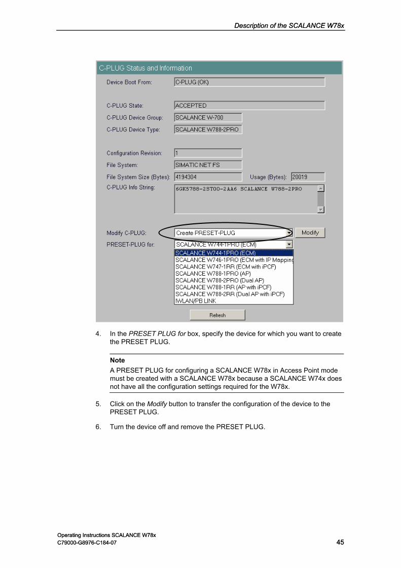
2. Start Web Based M
3. In the Modify C-PLUG list box, select the Create PRESET-PLUG entry.
Operating Instructions SCALANCE W78x
Description of the SCALANCE W78x Description of the SCALANCE W78x
Operating Instructions SCALANCE W78x 45 C79000-G8976-C184-07 C79000-G8976-C184-07
Operating Instructions SCALANCE W78x 45
4. In the PRESET PLUG for box, specify the device for which you want to create the PRESET PLUG.
Note A PRESET PLUG for configuring a SCALANCE W78x in Access Point mode must be created with a SCALANCE W78x because a SCALANCE W74x does not have all the configuration settings required for the W78x.
5. Click on the Modify button to transfer the configuration of the device to the PRESET PLUG.
6. Turn the device off and remove the PRESET PLUG.

Description of the SCALANCE W78x
Operating Instructions SCALANCE W78x 46
ESET PLUG in the C-PLUG slot of a powered-down SCALANCE W7xx and then turn on the device. The P1 and R1 LEDs flash yellow to signal
detected.
elect the Create P
4. want to create
5. f the device to the PRESET PLUG.
Turn the device off and remove the PRESET PLUG.
Using the vice
To work correctly, the PRESET PLUG must have a content that matches the target
C79000-G8976-C184-07
Changing a used PRESET PLUG
1. Insert the PR
that the PRESET PLUG was
2. Start Web Based Management, there you will see the current settings of the PRESET PLUG. Make the required changes to the configuration.
3. In the Modify C-PLUG list box, s RESET-PLUG entry.
In the PRESET PLUG for box, specify the device for which youthe PRESET PLUG.
Click on the Modify button to transfer the configuration o
6.
PRESET PLUG to commission a de
Note
device.
1. Insert the PRESET PLUG in the C-PLUG slot of the device to which you wanto assign a configuration.
t
CE W7xx with two wireless interfaces) flash yellow to signal that the PRESET PLUG was detected.
3. Press the reset button beside the C-PLUG briefly to save the settings of the PRESET PLUG on the device.
4. When all the data has been transferred from the PRESET PLUG to the device, the LEDs stop flashing and are permanently lit.
5. Turn the device off and remove the PRESET PLUG.
Note
The next time the device starts up, it uses the settings from the PRESET PLUG and the previous IP configuration.
2. Turn on the power to the device. The LEDs P1 and R1 (and R2 on a SCALAN

C79000-G8976-C184-07 47
Configuring the IP Address with the Primary S
4.1 Introduct
Primary Se
The ool is on the CD that ships with the SCALANCE W78x.
omation and Drives Service & Support on the Internet under entry ID 19440762. You will find this entry under the following URL:
http://support.automation.siemens.com/WW/view/en/19440762
etup Tool 4ion
tup Tool on CD and the Internet
Primary Setup T
The Primary Setup Tool is also available from Siemens Aut
Note
On the CD and on the Internet, you will find the latest version of the Primary Setup Tool (at the time of release of this document, Version 3.1). Make sure that you use the version V3.1 or higher for the SCALANCE W78x.
Operating Systems Supported
The Primary Setup Tool can be installed and used with the following operating systems:
Windows XP Professional
Windows 2000 Professional SP2
Operating Instructions SCALANCE W78x

Configuring the IP Address with the Primary Setup Tool
Operating Instructions SCALANCE W78x 48
The Primary Setup Tool uses the DLC protocol for communication with the s. Depending on the operating system you are using, you must work
h the following steps before you can use the DLC protocol:
Note
vers
C79000-G8976-C184-07
DLC Protocol
modulethroug
Windows XP Professional The DLC protocol is not supplied with Windows XP and must be installed and activated separately.
Windows 2000 Professional SP2 The DLC protocol is supplied with Windows 2000 but must be added to the active protocols.
The sections on installing the DLC protocol are relevant only for older firmware ions < V2.3.

Configuring the IP Address with the Primary Setup Tool
Operating Instructions SCALANCE W78x 49
dows XP Professional
Extracting the Archive File
llow the steps below to extract the files from the archive:
1. Double-click on the file name pst_install.exe in the Windows Explorer or start he Windows menu command Start > Run.
Installation
s below to install the DLC protocol on your computer:
2. In the Choose Setup Language dialog, select the language you want to use.
3. Click on the Next button in the first dialog.
4 In the next dialog, select the folder in which you want to install the program
C79000-G8976-C184-07
4.2 Installation of the DLC Protocol in Win
The files for installing the DLC protocol are in the self-extracting ZIP archivepst_install.exe. Fo
the program using t
2. In the dialog box of the extraction program, select the folder into which youwant to extract the files and click on the Extract button.
Follow the step
1. Double-click on the setup.exe file.
and click on the Next button to confirm your selection.
5. Close the last dialog of the installation program by clicking on the Finish button.

Configuring the IP Address with the Primary Setup Tool
Operating Instructions SCALANCE W78x 50
4.3 Installation of the DLC Protocol in Windows 2000 Professional SP2
ettings > Control Panel >Network and
3. erties.
5. d
6. firm
7. Close the properties dialog by clicking the OK button.
C79000-G8976-C184-07
Follow the steps below to install the DLC protocol on your computer:
1. Select the menu command Start > SDial-Up Connections.
2. Select the connection to your Ethernet communications module.
Right-click to open the context menu and select Prop
4. Click on the Install... button in the General tab.
In the Select Network Component Type dialog, select the entry Protocol anclick the Add... button.
In the Network Protocols window, select the entry DLC Protocol and conby clicking OK.

Configuring the IP Address with the Primary Setup Tool
Operating Instructions SCALANCE W78x 51
4.4 In
Procedure
Follow the r:
1. ws Explorer or start the
2. In thwan
3. The first dialog box of the Installation Wizard opens. Click on the Next button.
ion folder opens. Click on the Next rimary log box to
sele
S
5. If the DLC protocol is not installed on your computer, the Information dialog open OK and install t
6. ssful. Click on the
After installation of PST V3.1, start the tool with Start > SIMATIC > Primary Setup Tool.
C79000-G8976-C184-07
stalling the Primary Setup Tool
steps below to install the Primary Setup Tool on your compute
Double-click on the file name setup.exe in the Windoprogram using the Windows menu command Start > Run.
e Choose Setup Language dialog box, select the language in which you t to run the installation.
4. The dialog box for selecting the installatbutton if you want to accept the default C:\Program Files\Siemens\PSetup Tool\. If you want to use a different folder, you can open a dia
ct the folder by clicking the Browse button.
tart the installation by clicking the Next button.
s referring you to the ReadMe file. Confirm the dialog with he DLC protocol later as described in the ReadMe file.
A final dialog box informs you that the installation was succeFinish button to close this dialog box.

Configuring the IP Address with the Primary Setup Tool
Operating Instructions SCALANCE W78x 52
ary Setup Tool
Selecting t
After a elect the langu > Lang
Selecting the Network Adapter
If there is more than one network adapter in your computer, you can open the Settings > Network Adapter menu and specify which adapter is used by the Primary Setup Tool. This menu displays a maximum of four network adapters.
Browsing the Network
Before you assign IP addresses with the PST, you must first locate the w:
Select the Network > Browse menu command.
e F5 key.
ne.
C79000-G8976-C184-07
4.5 Working with the Prim
he Language
st rting the Primary Setup Tool, a dialog opens in which you sage for the program. You can also set the language in the Settingsuage menu.
configurable devices in the network. Start this search with the steps outlined belo
Press th
Click on the magnifier icon in the toolbar below the menu bar.
While the Primary Setup Tool browses the network, the Browse Network dialog is displayed with a progress bar. On completion of the search, the Primary Setup Tool displays a list with all the devices it has found in the left-hand pa

Configuring the IP Address with the Primary Setup Tool
Operating Instructions SCALANCE W78x 53
ring a Module
le-click on the
re. The Primary Setup Tool displays the input dialog for the configuration data in the right-hand pane of the
m window. Depending ed settings, some or s may x s alwa
because this addre t cannot be modified. Moreover, the Client-I re not supported by the SCALANCE W7xx
Configu
If you click an entry in the list, the Primary Setup Tool displays information on the selected device in the right-hand pane.
Follow the steps below to configure a device:
1. Click on the plus symbol in front of the device symbol or doubdevice symbol to display all interfaces of the device.
2. Click on the interface you want to configu
progracheck boxe
on the select text boxes ys disabled be disabled. The MAC address bo
ss is a property of the device thai
D and DNS parameters a.
3. Decide how the device will obtain its IP address:
Dynamically from a DHCP server: Select the Obtain IP address from DHCP server option button.
Manual assignment by the user: Select the Assign IP parameters option button.
C79000-G8976-C184-07

Configuring the IP Address with the Primary Setup Tool
Operating Instructions SCALANCE W78x 54
4. Make the following entries if you have decided to assign the IP address manually:
Enter the IP address for the device in the IP Address box. In each paa number betwebers.
Subnet Mask box.
If necessary, select the Use router check box and enter the IP address of the router in the text box. Router information is necessary if the computer on which you are creating the configuration is not in the same subnet as the device to be configured.
Downloading Configuration Data to the Module
r the configuration data to the device:
data is
from the left in the toolbar.
rt of en 0 the address separated by the periods, you can enter
and 255; the program does not accept any other num
Enter the subnet mask in the
Follow the steps below to transfe
1. Select the module you want to configure in the left pane of the program window. As long as an interface is selected and the input dialog for the configuration data is displayed, no download of the configuration possible.
2. Start the download by following the steps outlined below:
Select the Module > Download menu command.
Click on the second button
C79000-G8976-C184-07

Configuring the IP Address with the Primary Setup Tool
Operating Instructions SCALANCE W78x 55
tarting W sed Management
s below to start Web Based Management:
Select the menu command Module -> Start INC Browser.
Click on the third icon from the left in the toolbar (module with four blue wires).
S eb Ba
INCs (Industrial Network Components) such as a SCALANCE W7xx include Web Based Management. Select the device you want to configure with Web Based Management and follow the step
If the Module > Start INC Browser and the module icon are disabled, there is no Web Based Management for the selected module.
Removing a Module
You can remove a module from the list in the left-hand pane of the program window by selecting the Module > Remove Module menu command. Using this menu command has no effect on the existence of a module in the network; if you browse the network again, all modules are displayed again.
C79000-G8976-C184-07

Configuring the IP Address with the Primary Setup Tool
Operating Instructions SCALANCE W78x 56
Syntax
so use the Primary Setup Tool from the command line of a DOS prompt.
s7s77wnpstx MAC address IP address subnet mask [router address] 7wnpstx -NAME=station name [index network adapter][INC]
Co
C79000-G8976-C184-07
4.5.1 Primary Setup Tool via the Command Line
You can alThe syntax is as follows; optional parameters are shown in square brackets:
wnpstx MAC address -DHCP[=client ID] wnpstx MAC address -RESET
ss
The following table explains the parameters:
mmand Description Comment
MAC address The MAC address of the module to be configured.
-DHCP Specifies that the IP address is obtained from a DHCP server.
client ID nique identifier for the device. If this parameter is not specified, the
AC address as the ID.
Optional. A u
Primary Setup Tool uses the M
-RESET Sets the IP address to 0.0.0.0 .
IP add ss The nebe con
re w IP address of the module to figured.
subnet mask The new subnet mask of the module to be configured.
Router address The new IP address of the default router.
Optional.
-NAME Parameter for setting the station name.
station nam The station name assigned to the e module. Maximum length 255 characters (letters, numbers, slash, hyphen, and underscore).
Index netw pter. The default is "0".
Optional. ork adapter The index of the network ada
INC Identifier for a network component. Optional.

C79000-G8976-C184-07 57
Configuration Using the Wizards of Web B
5.1 In
b Based Management
Users enter the configuration data in the HTML pages sent by the SCALANCE W78x. The SCALANCE W78x evaluates this information and generates response pages dynamically.
The great advantage of this method is that apart from a Web browser, no special software is required on the client.
Requirements for Web Based Management
Once you have assigned an IP address with the Primary Setup Tool, you can continue to configure the device with Web Based Management.
To use Web Based Management, you should ideally have a wired network connection between the SCALANCE W78x and the client computer. In principle, it is possible to use Web Based Management over a wireless network, however the SCALANCE W78x can be set so that access over a wireless network is disabled.
We recommend that you use the Microsoft Internet Explorer Version 5.5 or higher or Mozilla Firefox Version 1.5 or higher.
All the pages of Web Based Management require JavaScript. Make sure that your browser settings allow this.
Since Web Based Management is HTTP-based on, you must allow access to Port 80 or Port 443 for HTTPS if you have a firewall installed.
ased Management 5troduction
Principle of We
The SCALANCE W78x has an integrated HTTP server for Web Based Management. If the SCALANCE W78x is accessed by an Internet browser, it returns HTML pages to the client computer depending on user input.
Operating Instructions SCALANCE W78x

Configuration Using the Wizards of Web Based Management
Operating Instructions SCALANCE W78x 58
er ce of
C79000-G8976-C184-07
Note The screenshots in this section were created using the Microsoft Internet Explorversion 6.0. If you use a different browser (for example Mozilla), the appearanthe menus may differ.

Configuration Using the Wizards of Web Based Management
Operating Instructions SCALANCE W78x 59
ed Management and Logging On
1. In the address box of the Web browser, enter the IP address or the URL of the SCALANCE W78x. If there is a problem-free connection to the SCALANCE W78x, the Logon dialog of Web Based Management is displayed:
5.2 Starting Web Bas
Procedure
2. In the "User Name" list box, select the "Admin" entry if you want to change settings of the SCALANCE W78x (read and write access). If you select the "User" entry, you only have read access to the configuration data of the SCALANCE W78x.
3. Enter your password. If you have not yet set a password, the default passwords as shipped apply: Enter admin if you selected "admin" as the user name or user if you selected "user".
4. Click on the "Log On" button to start the logon.
C79000-G8976-C184-07

Configuration Using the Wizards of Web Based Management
Operating Instructions SCALANCE W78x 60
5.2.1 Co
Descriptio
f the E W7xx and confirm with Enter. The warning Security Alert is displayed
and asks you whether you want to continue the action. Confirm with YES. The Login dialog of Web Based Management opens.
C79000-G8976-C184-07
nnection over HTTPS
n
Web Based Management also allows you to connect to the device over the secureconnection of the HTTPS protocol.
Enter https:// in the address field of the Internet browser and the IP address oSCALANC

Configuration Using the Wizards of Web Based Management
Operating Instructions SCALANCE W78x 61
izards
, Security Wizard and iPCF-Wizard
ithout detailed knowledge of wireless technology. A wizard consists of a series of dialogs in which you enter the basic configuration data.
There is a wizard for general settings to ensure the basic functionality of the SCALANCE W78x. The wizard for the security settings supports you when setting security-related parameters. A further wizard is available in client mode to configure the iPCF mechanism (industrial Point Coordination Function).
Wizard Status
After selecting the "Wizards" menu on the left-hand side of the dialog, the status of the wizards is displayed. If you have worked through a wizard completely, Done is displayed as the status. If you have worked through all wizards, the Wizards entry moves to the bottom end of the menu.
5.3 Selecting the W
Basic Wizard
Web Based Management provides several wizards that allow straightforward commissioning w
C79000-G8976-C184-07

Configuration Using the Wizards of Web Based Management
Operating Instructions SCALANCE W78x 62
Some pages of the Wizards have a different content in access point mode and case, there is a separate description for the alternatives.
C79000-G8976-C184-07
Note
client mode. In thisYou can specify the mode in the System menu.

Configuration Using the Wizards of Web Based Management
Operating Instructions SCALANCE W78x 63
5.4.1 IP
Descriptio
One of the basic steps in configuration of an Ethernet device is setting the IP address. The IP address identifies a device in the network uniquely. On this page, you enter the information for IP configuration of the SCALANCE W78x.
5.4 Basic Wizard
Settings
n
Specified I
devices: The IP address can be set as a fixed permanent address or can be obtained dynamically from a DHCP
Specified IP Address" if you do not use a DHCP server.
IP Address
P Address / DHCP Server Option buttons
There are two methods of assigning IP addresses to
server. Select "
input box
The IP address of the SCALANCE W78x. Here, you enter an address that is unique within the network.
C79000-G8976-C184-07

Configuration Using the Wizards of Web Based Management
Operating Instructions SCALANCE W78x 64
The subnet mask specifies the range of addresses within which communication n take place.
y of the SCALANCE W78x
Management Agent at this bit position can communicate with the SCALANCE W78x.
Example
Let us assume that the IP address of the SCALANCE W78x is set to
unication partner must match the bit pattern of the SCALANCE W78x exactly at this point. The same applies to the second and third parts of the IP address. The IP address of a communication partner must therefore start with 192.168.147. The bit pattern of 0 is 0000 0000. This means that the bit pattern of the last part of the IP address of the partner device does not need to match the address of the SCALANCE W78x at any point; in other words, it can be any number.
C79000-G8976-C184-07
Subnet Mask input box
ca
The four numbers of an IP address separated by periods are interpreted as a bit pattern. If a one is set at a bit position within the subnet mask, this means that onldevices with an IP address the matches the IP address
192.168.147.189 and the subnet mask is set to 255.255.255.0. The bit pattern for 255 is 1111 1111. This means that the bit pattern of the first number of the IP address of a comm

Configuration Using the Wizards of Web Based Management
Operating Instructions SCALANCE W78x 65
5.4.2 System name
Description
The device name also identifies a network node but means more to the user than the IP address.
System Nam
In this box, you enter the device name for your SCALANCE W78x. This parameter a
e text box
corresponds to the sysName SNMP parameter. The device name can be up tomaximum of 255 characters long. If you also want to use this parameter for WDSor redundancy, the maximum length is 32 characters.
C79000-G8976-C184-07

Configuration Using the Wizards of Web Based Management
Operating Instructions SCALANCE W78x 66
de
is mandatory for operation complying with the
untry different from the country of use can lead to legal prosec
5.4.3 Country Co
Note The correct country settingapprovals. Selecting a co
ution!
Descriptio
Some divisions for WLAN communication. The regulations for maximum output power also differ from country to country.
pecify which local regulaparam
n
countries have different frequency band
When you configure the SCALANCE W78x, you must stions are relevant for your location. You do this with the Country code eter.
Country code list box
In this list box, you select the country in which the SCALANCE W78x will be operated. You do not need to know the data for the specific country, the channel division and output power are set by the SCALANCE W78x according to the country you select.
C79000-G8976-C184-07

Configuration Using the Wizards of Web Based Management
Operating Instructions SCALANCE W78x 67
5.4.4 Wireless Settings in Access Point Mode
On this page, you specify the configuration of the wireless network. This includes
pears o allow you to configure the second wireless adapter. You can
make different settings for "WLAN1" and "WLAN2".
Description
the network name and the transmission mode. If you are configuring the SCALANCE W788-2PRO and SCALANCE W788-2RR models, this page apa second time t
SSID text box
Enter the name of your network in this box. The SCALANCE W78x allows all characters except the percent character for the SSID. To ensure compatibility with partner devices, you should, however, not use any characters that are peculiar to a particular language (for example special German characters ä, ö etc.). The string for SSID can be a maximum of 32 characters long.
Wireless Mode list box
Select a wireless mode that is supported by all partner devices. On the SCALANCE W788-2PRO and SCALANCE W788-2RR, it may be a practical to set a different transmission mode for each wireless adapter to allow optimum support of different clients. The effect of the 802.11.b + g setting is that all the settings in the Advanced G menu are taken into account as far as possible but that compatibility with devices conforming to IEEE 802.11 b guaranteed.
C79000-G8976-C184-07
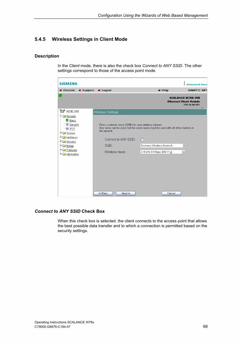
Configuration Using the Wizards of Web Based Management
Operating Instructions SCALANCE W78x 68
her
5.4.5 Wireless Settings in Client Mode
Description
In the Client mode, there is also the check box Connect to ANY SSID. The otsettings correspond to those of the access point mode.
Connect to ANY SSID Check Box
When this check box is selected, the client connects to the access point that allows the best possible data transfer and to which a connection is permitted based on the security settings.
C79000-G8976-C184-07

Configuration Using the Wizards of Web Based Management
Operating Instructions SCALANCE W78x 69
dress Settings (Client Mode only)
Assigning
ernet port of the SCALANCE W78x client before it can be reached. This MAC address is used
client for wireless communication with the access point.
nt,
– Automatically, the client adopts the source MAC address of the first frame that it receives over the Ethernet interface.
– Manual entry by the user.
s.
AC addresses need to be served downstream from the client, the following setting is available for SCALANCE W746-1PRO and SCALANCE W747-1RR:
– Layer 2 Tunneling
This setting meets the requirements of industrial applications in which MAC address-based communication with several devices downstream from the client is required. Clients with this setting cannot connect to standard Wi-Fi devices and SCALANCE W access points with firmware V3.0 or older.
Note
The layer 2 tunneling setting is available only with the following model variants: • SCALANCE W78x in client mode • SCALANCE W746-1PRO • SCALANCE W747-1RR
C79000-G8976-C184-07
5.4.6 Adopt MAC Ad
the MAC Address
A MAC address must be specified for the device connected to the Eth
by the
If there is precisely one MAC address to be served downstream from the cliethere are two ways of doing this:
These settings have no effect on communication with standard Wi-Fi device
If up to eight M
The SCALANCE W746-1PRO and SCALANCE W747-1RR devices can also provide access to a wireless network for several Ethernet devices (IP mapping). For an access point with MAC filtering, only one MAC address is visible to the SCALANCE W78x client, there can be no filtering according to the MAC addresses of the Ethernet devices.

Configuration Using the Wizards of Web Based Management
Operating Instructions SCALANCE W78x 70
re, select how the SCALANCE W78x client obtains a MAC address. The llowing are possible:
he source MAC address of the first frame that it receives over the Ethernet interface.
AC address manually.
Adopt own MAC (not for SCALANCE W744-1PRO)
The SCALANCE W74x uses the MAC address of the Ethernet interface for the WLAN interface.
AN interface. The network is also informed of the MAC addresses connected downstream from the SCALANCE W746-1PRO or SCALANCE W747-RR.
MAC mode list box
Hefo
Auto find 'Adopt MAC'
The SCALANCE W78x client automatically adopts t
Set 'Adopt MAC' manually
You enter the M
Layer 2 Tunneling (not for SCALANCE W744-1PRO)
SCALANCE W74x uses the MAC address of the Ethernet interface for the WL
C79000-G8976-C184-07

Configuration Using the Wizards of Web Based Management
Operating Instructions SCALANCE W78x 71
Adopt MAC text box
If the Set 'Adopt MAC' manually check box is selected, you will need to enter the MAC address of the device connected to the SCALANCE W78x client over Ethernet here.
If you do not want layer 2 communication to be handled over the SCALANCE W78x client, but only send higher IP-based frames to one or more connected devices, you can also leave the default setting Adopt Own Mac. In this mode, the client registers with the MAC address of its Ethernet adapter. The IP packets are broken down according to an internal table and forwarded to the connected devices.
The Adopt MAC box is hidden in the "Auto find 'Adopt MAC' " and "Layer 2 Tunneling" modes.
C79000-G8976-C184-07

Configuration Using the Wizards of Web Based Management
Operating Instructions SCALANCE W78x 72
ly in access point mode)
Description
The SCALANCE W78x uses a specific channel within the frequency band for
ecific channel must be set, for example, in the following situations:
r another wireless network.
Use of the redundancy function. In this case, two well spaced channels or two different frequency bands must be selected.
Use of WDS. In this case, select a problem-free channel that is also used by the WDS partner.
5.4.7 Channel Settings (on
communication. You can either set this channel specifically or configure the SCALANCE W78x so that the channel is selected automatically. A sp
Communication suffers from interference from another device (for example microwaves) o
Auto Channel Select Check Box
Select this check box if you do not have any particular requirements regarding channel selection.
C79000-G8976-C184-07

Configuration Using the Wizards of Web Based Management
Operating Instructions SCALANCE W78x 73
Here, you select a channel suitable for your application. You can only select from annel Select check box is not selected. The entries in the list evious selection made in the Country code box and on the
If your SCALANCE W78x has a second wireless adapter (SCALANCE W788-
e is
C79000-G8976-C184-07
Radio Channel list box
this list if the Auto Chbox depend on the prmode (IEEE 802.11a, IEEE 802.11b, IEEE 802.11g, IEEE 802.11h).
Note
2PRO, SCALANCE W788-2RR), this adapter is deactivated when the devicshipped. You can use the second wireless adapter after you have selected the channels.
Notice When operating a second wireless adapter, make sure that there is adequate channel spacing.
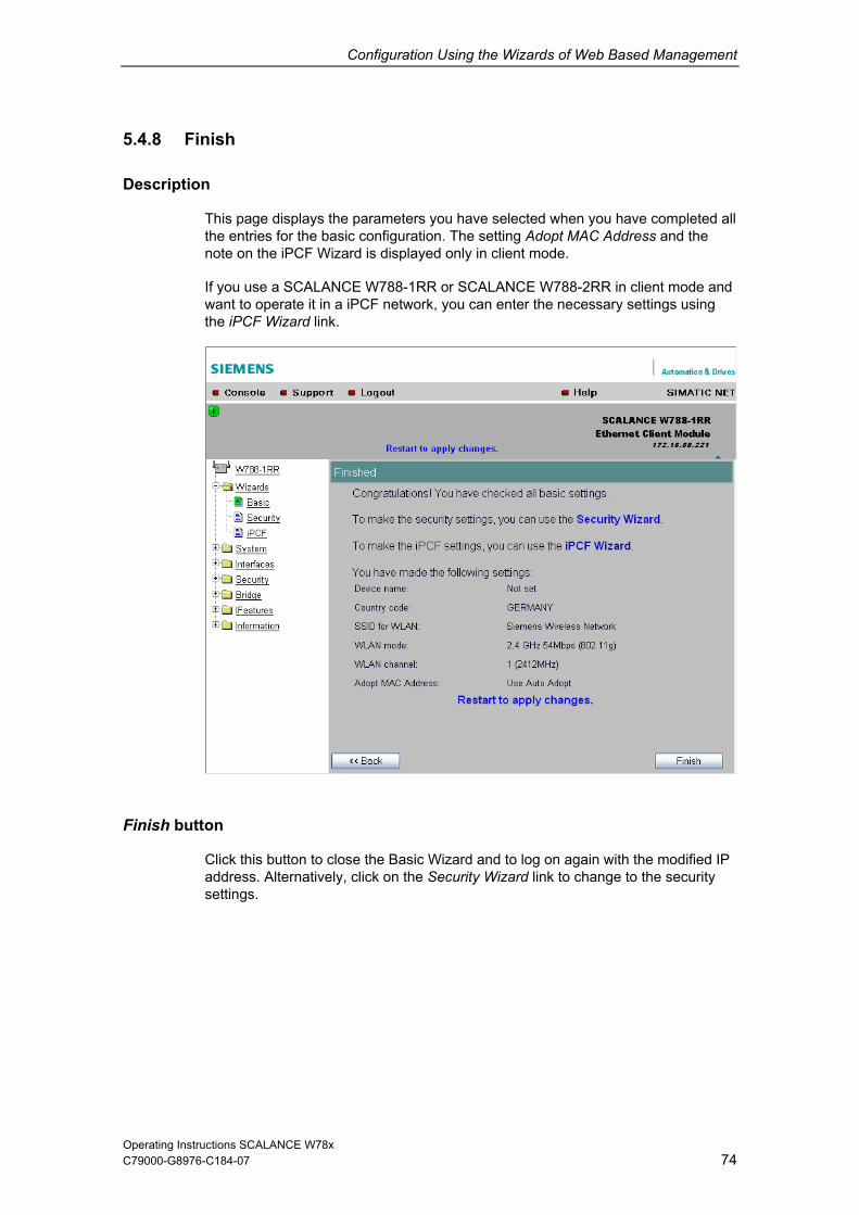
Configuration Using the Wizards of Web Based Management
Operating Instructions SCALANCE W78x 74
Description
This page displays the parameters you have selected when you have completed all
de and essary settings using
the iPCF Wizard link.
5.4.8 Finish
the entries for the basic configuration. The setting Adopt MAC Address and the note on the iPCF Wizard is displayed only in client mode.
If you use a SCALANCE W788-1RR or SCALANCE W788-2RR in client mowant to operate it in a iPCF network, you can enter the nec
Finish button
Click this button to close the Basic Wizard and to log on again with the modified IP address. Alternatively, click on the Security Wizard link to change to the security
settings.
C79000-G8976-C184-07

Configuration Using the Wizards of Web Based Management
Operating Instructions SCALANCE W78x 75
Introduction
Note
operated even if you do not set the security properties of your network, there is then, however,
C79000-G8976-C184-07
5.5 Security Wizard
With the Security Wizard, you can specify security-related parameters without detailed knowledge of security technology in wireless networks.
The SCALANCE W78x can beparameters. Depending on thean increased risk of unauthorized access. You should therefore work through all the pages of the Security Wizard, so that you have at least basic security functions.

Configuration Using the Wizards of Web Based Management
Operating Instructions SCALANCE W78x 76
.5.1 Security Settings
is
password for the admin user is admin. You can use the wizards only if you log on as administrator.
5
Password
First, set a new admin password. Enter the string twice in the text boxes of thpage. The password can be up to a maximum of 31 characters long.
Until you set a password, the defaults set in the factory apply: The default
C79000-G8976-C184-07

Configuration Using the Wizards of Web Based Management
Operating Instructions SCALANCE W78x 77
nagement Interfaces
Protocols for
of thcon d only select protocols that you actually use.
restthe
Specifying the Network Type for Configuration
It is easier to re ess to a wired network t Web B gement cess to th ANCE x for co r ut C W78x with a cablthis, check the box at the bottom of the page.
5.5.2 Security Settings for Ma
Configuration
In this page, you specify the protocols with which you can access the configuratione SCALANCE W78x. All protocols with a selected check box can be used for
figuration. You shoul
The protocol settings only take effect after exiting the Security Wizard and arting. Even after selecting the Web Based Management entry, you still have option of returning to earlier pages or exiting the wizard.
strict acc han to a wireless network. ased Mana
estricted to comp allows acers linked to the S
e SCALALANCE
W78 nfiguration to bee. If you require
C79000-G8976-C184-07

Configuration Using the Wizards of Web Based Management
Operating Instructions SCALANCE W78x 78
Access Permissions using the SNMP Protocol
When using the SNMP protocol, you specify access permissions by means of the community string. A community string effectively combines the function of user name and password in one string; different community strings are defined for read and write permissions. More complex and more secure authentications are possible only in some SNMPv2 variants and in SNMPv3.
To preserve security, you should not use the default values public or private.
5.5.3 Security Settings for SNMP Protocol
Write Community String text box
Here, you enter the write community string (maximum of 63 characters) for the SNMP protocol.
SNMP Read Only Check Box
If you select this check box, only read access is possible with the SNMP protocol V1 or V2c.
C79000-G8976-C184-07

Configuration Using the Wizards of Web Based Management
Operating Instructions SCALANCE W78x 79
5.5.4 Security Settings for WLAN (Page 1, only in access point mode)
Description
u ty udingauthentication and encryption. If you are configuring the E W78 or SCALA s appear a se nd time to allow you to configu se ada can make different settingsWLAN1 and WLAN2.
Network-Specific Security
On t e firs e o ty settin elect set ply reg ss of protocol-specific c measures for securing a network against unauthorized acce
ly c ose ame (SSID) of AP e CE W78
clud lien ca ireless c rom the wired part of the netw
C79000-G8976-C184-07
On this page, yo make the securi settings, incl , for example, the SCALANC 8-2PRO
NCE W788re the
-2RR models, thecond wireless
se pagepter. You
co for
Settings
h t pag f the securi restrictions. The basi
gs, you s tings that ap ardle
ss involve
allowing on ertain clients (th that have enter the network nthe ) to communicate with th SCALAN x.
ex ing c ts that communiork.
te over w onnections f

Configuration Using the Wizards of Web Based Management
Operating Instructions SCALANCE W78x 80
SSID text box
Enter the name of your network in this box (maximum of 255 characters, 32 undancy function). To avoid any possible conflicts with
settspe
Suppress SSID broadcasting check box
An entry in this check box means that the SSID is not visible for other device. As a result, only stations for which the same network name was configured as for the SCALANCE W78x can connect to the SCALANCE W78x.
characters if you use the redings for a specific locale on the computer, the name should not include any cial German characters (ö, ä etc.).
C79000-G8976-C184-07

Configuration Using the Wizards of Web Based Management
Operating Instructions SCALANCE W78x 81
ote
C79000-G8976-C184-07
NSince no encryption is used for the SSID transfer, this function can only provide basic protection against unauthorized access. The use of an authentication method(for example WPA (RADIUS) or WPA-PSK if this is not possible) provides higher security. You must also expect that certain end devices may have problems withaccess to a hidden SSID.
Inter SSID Com
Selecting this check box allows communication between WLAN clients registered
E ent SSIDs for
each of the wireless cards.
munication check box
at different SSIDs of an access point.
xample 1: A SCALANCE W788-2xx was defined with differ
Example 2: A SCALANCE W788-1xx is used with multiple SSIDs.
Note
E W788-2xx, the Inter SSID communication function must be WLAN interfaces or on all VAPs to allow communication between
On a SCALANCenabled on boththe clients with different SSIDs.
Note
If VLANs are configured for the SSIDs, this setting can prevent communication ing to the VLAN rules. between the SSIDs accord
Intracell Communication list box
Intracell blocking This setting prevents WLAN client communication within an SSID.
Ethernet blocking This setting prevents WLAN client communication over the Ethernet interface of the access point.
Disabled This setting enables both WLAN client communication within an SSID as well as WLAN client communication over the Ethernet interface.
To illustrate the situation, there is an overview of the effects of the Inter SSID Communication and Intracell Communication settings below.

Configuration Using the Wizards of Web Based Management
Operating Instructions SCALANCE W78x 82
Possible Communication
C79000-G8976-C184-07
Settings Inter SSID
mmunication Intracell Communication
within an SSID
with another SSID
to the Ethernet network co
Enabled Disabled x x x Enabled Intracell
blocking x x
Enabled Ethernet x x blocking
Disabled Disabled x x Disabled Intracell
blocking x
Disabled Ethernet blocking
x

Configuration Using the Wizards of Web Based Management
Operating Instructions SCALANCE W78x 83
5.5.5 Security Settings for WLAN (Page 2)
Predefined Security Levels
Authentication and encryption are tried and tested methods for increasing security in networks. Web Based Management provides five predefined security levels that specify suitable methods.
C79000-G8976-C184-07

Configuration Using the Wizards of Web Based Management
Operating Instructions SCALANCE W78x 84
The following table indicates what the various security levels involve.
Visible in Level Authentication Encryption Type of
Encryption Encryption key source
C79000-G8976-C184-07
Wizard
x None Open System disabled without not applice
abl
None Open System enabled as option WEP / AES local
x Low Shared Key enabled WEP / AES local
x Medium IEEE 802.1x enabled WEP Server
High WPA-PSK Key)
enabled TKIP / AES local (preshared
Highest WPA (Radius) enabled TKIP / AES Server
x High WPA2-PSK enabled TKIP / AES local (preshared Key)
x Highest WPA2 (Radius) enabled TKIP / AES Server
High WPA-Auto-PSK (preshared Key)
enabled TKIP / AES local
Highest WPA-Auto (Radius)
enabled TKIP / AES Server
Authentication
Authentication basically means that some form of identification is required. Authentication therefore protects the network from unwanted access. In the Security Level box, you can choose between the following types of authentication:
None (Open System) There is no authentication. Encryption with a fixed (unchanging) key can be selected as an option. Based are the key length, you can choose between WEP and AES. To do this, define a key in the Keys menu. 5 or 13 ASCII or 10 or 26 hexadecimal characters specify a weak WEP key (40/104 bits). 16 ASCII or 32 hexadecimal characters, on the other hand, define a strong AES key (128 bits). Then select Encryption in the Basic WLAN menu.
Low (Shared Key) In Shared Key authentication, a fixed key is stored on the client and access point. This is then used for authentication and encryption. In this case, you will have to store a WEP or AES key after selecting Low (Shared Key).

Configuration Using the Wizards of Web Based Management
Operating Instructions SCALANCE W78x 85
Port-related access check over an external RADIUS server (IEEE 802.1x). With IUS server based on a certificate (EAP-
TLS) or a combination of user name and password (EAP-PEAP or EAP-TTLS / internal authentication method MSCHAPv2). As an option, the RADIUS server
n identifies itself to the client using a certificate. Following successful
C79000-G8976-C184-07
Medium (IEEE 802.1x)
this method, the client logs on at a RAD
theauthentication, the client and RADIUS server generate key material that is used for data encryption. WEP is used as a weak encryption method.
High (WPA2-PSK) WPA2-PSK is based on the WPA2 standard, WPA authentication, however, operates without a RADIUS server. Instead of this, a key (pass phrase) is stored on every client and access point and this is used for authentication and further encryption. AES or TKIP is used as the encryption method, AES represents the standard method.
Highest (WPA2) WPA2 (Wi-Fi Protected Access 2) is a further development of WPA and implements the functions of the IEEE 802.11i security standard. WPA2 uses the additional encryption protocol CCMP that allows fast roaming in mobile ad hoc networks with its preauthentication. A client can log on in advance and several access points so that the normal authentication can be omitted. A RADIUS server is used to authenticate the client with an access point. The client logs on at a RADIUS server based on a certificate (EAP-TLS) or a combination of user name and password (EAP-PEAP or EAP-TTLS / internal authentication method MSCHAPv2). As an option, the RADIUS server then identifies itself to the client using a certificate. Following successful authentication, the client and RADIUS server generate key material that is used for data encryption. AES or TKIP is used as the encryption method, AES represents the standard method.
High (WPA-Auto-PSK) Setting with which an access point can process both the WPA-PSK as well as WPA2-PSK type of authentication. This is necessary when the access point communicates with different clients, some using WPA-PSK and others WPA2-PSK. The same encryption method must be set on the clients.
Highest (WPA-Auto) Setting with which an access point can process both the WPA and WPA2 type of authentication. This is necessary when the access point communicates with different clients, some using WPA and others WPA2. The same encryption method must be set on the clients.

Configuration Using the Wizards of Web Based Management
Operating Instructions SCALANCE W78x 86
. You can only disable encryption in the Encryption check box if you have selected Open System for authentication in the Basic WLAN menu. All other security methods include both authentication and encryption. Various schemes are used for
WEP (Wired Equivalent Privacy) am encryption method with only 40- or 104-bit long lgorithm (Ron’s Code 4).
ecognize corrupted packets.
AES (Advanced Encryption Standard) Strong symmetrical block encryption method based on the Rijndael algorithm that further improves the functions of TKIP.
Encryption key source
The encryption key source indicates whether the key is configured locally and fixed (local) or whether it is negotiated by a higher protocol and an authentication server (server).
Security Level for WLAN list box
Select a security level that is supported by all clients. The content of the next page depends on the selected security level. If you select the security level None, there is no following page since neither encryption nor authentication will be used.
C79000-G8976-C184-07
Encryption
Encryption protects the transferred data from eavesdropping and corruption
encryption:
A weak, symmetrical strekeys based on the RC4 a
TKIP (Temporal Key Integrity Protocol) A symmetrical stream encryption method with the RC4 algorithm (Ron’s Code 4). In contrast to the weak WEP encryption, TKIP uses changing keys derived from a main key. TKIP can also r

Configuration Using the Wizards of Web Based Management
Operating Instructions SCALANCE W78x 87
for the Security Level Low 5.5.6 Settings
Default Key list box
Select the WEP key or AES key you want to define.
Key text box
Enter the character string for the key here. The key can be entered as ASCII characters or alternatively as hexadecimal digits (0 – F). If the key was entered in ASCII format, this is later displayed in quotes.
Length list box
Select the key length you want to use here. If the length of the string in the Key text box is longer or shorter than the selected key length, an error message is
layed. The following key lengths are possible:
40 bits WEP (5 ASCII characters or 10 hexadecimal numbers)
128 bits AES (16 ASCII characters or 32 hexadecimal numbers)
disp
104 bits WEP (13 ASCII characters or 26 hexadecimal numbers)
C79000-G8976-C184-07

Configuration Using the Wizards of Web Based Management
Operating Instructions SCALANCE W78x 88
, the maximum key length is also 128 bits.
.5.7 Settings for the Security Level Medium in Access Point Mode
With the Auto setting
5
Authorization Lifetime text box
uthentication in seconds. The minimum time is 1 e is 12 hours (enter 43200). The default is 1
RADIUS Se
In addition to the IP address and the port, you must also specify a password (maximum 128 characters) and confirm it in a second box. In the Maximum Retransmissions text box, you enter the maximum number of transmission attempts. The maximum possible value is 5, the default is 2.
Enter the period of validity of the aminute (enter 60), the maximum timhour (3,600 seconds).
rver Table
You can enter the data for two RADIUS servers; the information in the Backup column is used if the server defined in the Primary column is not available.
C79000-G8976-C184-07

Configuration Using the Wizards of Web Based Management
Operating Instructions SCALANCE W78x 89
Medium in Client Mode 5.5.8 Settings for Security Level
Dot1x user name text box
enter the user name with which you want to register over the RADIUS server.
Dot1x user password text box
Here, enter the password for the above user name. The client logs on with the RADIUS server using this combination when a logon with a certificate was not possible.
Password confirmation text box
Confirm the password here.
Here,
C79000-G8976-C184-07

Configuration Using the Wizards of Web Based Management
Operating Instructions SCALANCE W78x 90
el High 5.5.9 Settings for the Security Lev
Pass phrase text box
Here, you enter a WPA2 key. The key can be 8 to 63 ASCII characters or exactly 64 hexadecimal characters long. This initialization key must be known on both the client and the SCALANCE W78x and is entered by the user at both ends.
Pass phrase confirmation text box
Here, you confirm the entered WPA2 key.
or exactly 64 hexadecimal characters
long plex for example consisting of random -/lowercase), have few repetitions and special characters).
t or ifsec
Note The key can be 8 to 63 ASCII characters
. It should be selected so that is comnumbers, letters (upperDo not use known names, words or terms that could be guessed. If a device is los
the key becomes known, the key should be changed on all devices to maintain urity.
C79000-G8976-C184-07

Configuration Using the Wizards of Web Based Management
Operating Instructions SCALANCE W78x 91
Highest
s you can set correspond to those of the Medium security level.
5.5.11 The Following Settings Were Made
cted Settings
ettings. If you want to change a setting, you can click on the Back button to return to a previous page
re you can enter a different value or make a different selection. In client mode, page contains less information.
5.5.10 Settings for the Security Level
The option
Overview of the Sele
This page contains an overview of the selected security s
whethis
C79000-G8976-C184-07

Configuration Using the Wizards of Web Based Management
Operating Instructions SCALANCE W78x 92
5.5.12 Finish
Exiting the Wizard
The last page of the wizard indicates other security measures that you can take. If you still want to make final modifications, you can open the relevant pages by clicking on the texts highlighted in blue:
IP Filter opens the Security > Access page.
Access Control List for WLAN 1 (WLAN 2) opens the Security > ACL page for wireless adapter 1 or 2.
This link is available only in access point mode.
To apply changes perform restart opens the System > Restart page.
Finish button
Click the Finish button to exit the Wizard. Your settings only take effect after you have restarted (System > Restart menu).
C79000-G8976-C184-07

Configuration Using the Wizards of Web Based Management
C79000-G8976-C184-07 93
.6 iPCF Wizard
SCALANCE W788-1R
5
Note The iPCF Wizard is available only in client mode of the SCALANCE W788-2RR.
R or
Note
The iPCF wizard also includes pages for specifying security settings. If you use iPCF, you do not therefore need to work through the Security Wizard.
5.6.1 i Point Coordination Function Settings
Channel Selection and Transmit Power
make the setting is necessary for iPCF. The main advantage of is that you can improve roaming times and reduce the interference
affecting other systems or segments.
On this page, yousuitable settings
Operating Instructions SCALANCE W78x

Configuration Using the Wizards of Web Based Management
C79000-G8976-C184-07 94
t
Wireless standard
Note When using iPCF, the following maximum data rates must be taken into accounwhen setting the access point:
Max. data rateIEEE 802.11a/h 12 Mbps IEEE 802.11b 11 Mbps IEEE 802.11g 12 Mbps
Background scan ch. select check box
or an access point is a major factor in the reduction of handover times. To use this function, activate the
ch. select list box and enter the channels on which access points ode can actually be reached in the Background scan channels
Background scan channels text box
Here, enter the channels on which access points operating in iPCF mode can be reached by the client. If you enter more than one channel, each channel must be separated by a blank.
Transmit power list box
When using antennas, it may be necessary to reduce the transmit power to avoid exceeding the legal maximum transmit power or to restrict the visibility of the radio link. If necessary, select the required reduction in transmit power here.
A reduction of transmit power may also necessary to avoid interfering with other cells because a reduced transmit power means a reduction in the span of the cell.
Antenna Mode list box
This list box specifies the use of the antennas. If Diversity is set, the SCALANCE W78x uses the only antenna that allows the best possible data transmission. For each WLAN interface, both antennas must be connected. Both antennas should also be of the same type and they should also illuminate approximately the same space. If an access point is operated with the diversity setting and the two antennas span different cells, this can have negative effects. Otherwise, you must select the connected antenna. For the IWLAN-PB LINK, select Antenna A (see 6.3.3 section Antennas).
Select this check box to restrict the number of channels on which the client searches for an access point. This results in a reduction of handover times.
Restricting the channels on which a client searches f
Background scan operating in iPCF mbox.
Operating Instructions SCALANCE W78x

Configuration Using the Wizards of Web Based Management
C79000-G8976-C184-07 95
Note If only one antenna is connected, the connected antenna must be set permanently.
cond antenna socket must also have a 50 Ω terminator fitted.
The se
Operating Instructions SCALANCE W78x
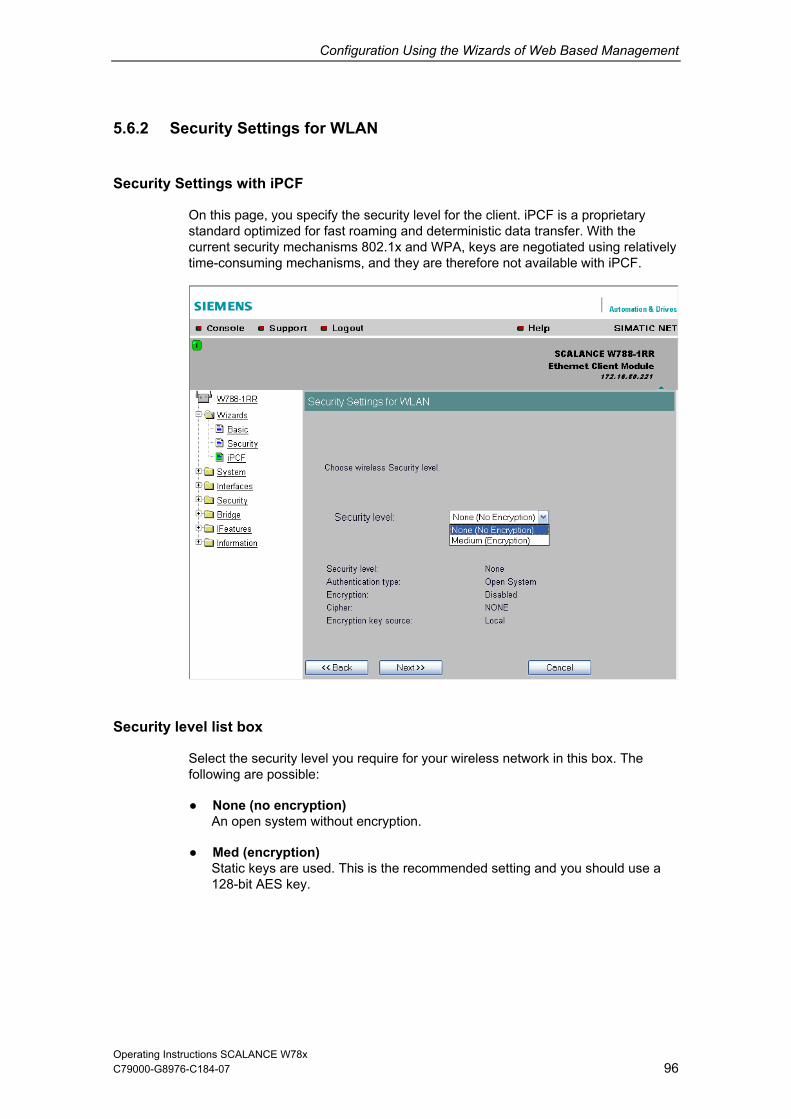
Configuration Using the Wizards of Web Based Management
5.6.2 Security Settings for WLAN
C79000-G8976-C184-07 96
optimized for fast roaming and deterministic data transfer. With the current security mechanisms 802.1x and WPA, keys are negotiated using relatively
Security Settings with iPCF
On this page, you specify the security level for the client. iPCF is a proprietary standard
time-consuming mechanisms, and they are therefore not available with iPCF.
Security le
None (no encryption) An open system without encryption.
Med (encryption) Static keys are used. This is the recommended setting and you should use a 128-bit AES key.
vel list box
Select the security level you require for your wireless network in this box. The following are possible:
Operating Instructions SCALANCE W78x

Configuration Using the Wizards of Web Based Management
C79000-G8976-C184-07 97
Specifying
age.
5.6.3 Public Security Key for WLAN
the Key
If you have selected the security level Med, you must specify the key on this p
Default Key list box
Select the WEP key or AES k
Key text box
Enter the character string for the key here. The key can be encharacters or alternatively as hexadecimal digits (0 – F). If the key was entered in ASCII format, this is lat
Length list box
Select the key length you want to use here. If the length of the string in the Key text box is longer than the selected key length, an error message is displayed. The following key lengths are possible:
40 bits (5 ASCII characters or 10 hexadecimal numbers)
ey you want to define.
tered as ASCII
er displayed in quotes.
Operating Instructions SCALANCE W78x

Configuration Using the Wizards of Web Based Management
C79000-G8976-C184-07 98
aracters or 26 hexadecimal numbers)
128 bits (16 ASCII characters or 32 hexadecimal numbers)
With the Auto setting, the maximum key length is also 128 bits.
5.6.4 Fi
Exiting the
104 bits (13 ASCII ch
nish
Wizard
The last page of the iPCF Wizard shows you all the settings you have made so thatyou can make a final check.
Finish butt
Click the Finish button to exit the iPCF Wizard. Your settings only take effect after you have restarted (System > Restart menu).
on
Operating Instructions SCALANCE W78x

C79000-G8976-C184-07 99
ConManagement and the Command Line Interface
6
6.1 General Information on Web Based Management and the Co
6.1.1 In
ontents o Chapter
e SCALANCE W78x.
Web Based Management provides you with configuration options way beyond those described in the previous chapter. You will also find a detailed description of the individual elements of a page in the online help.
As an alternative, you can also configure the device using the Command Line Interface (CLI). This allows remote configuration over Telnet.
This chapter describes both configuration methods together because the menu structure of Web Based Management is the same as the structure of the CLI commands.
Note
You should only use the command line interface if you are an experienced user. Even commands that bring about fundamental changes to the configuration are normally executed without a prompt for confirmation.
figuration Using Web Based
mmand Line Interface
troduction
C f This
This chapter explains the possible settings for th
Note on Login User
If you log on as user, you will only have restricted use of WEB and Telnet. Since you only have read access, some commands do not exist in Telnet and some areas cannot be selected.
Operating Instructions SCALANCE W78x

Configuration Using Web Based Management and the Command Line Interface
C79000-G8976-C184-07 100
Required Experience
rmation in this chapter effectively, you should have a etwork technology and WLANs.
6.1.2 Th
Display of t
Topeacc Based Management therefore displays simulated LEDs.
Activating
To be able to use the infothorough knowledge of n
e LED Simulation of Web Based Management
he Operating State
he SCALANCE W78x has one or more LEDs that provide information on the rating state of the device (see Chapter 2). Depending on its location, direct ess to the SCALANCE W78x may not always be possible. Web
the Simulation
There is an HTML-based simulation of the LED status. Click on the green icon below the Console link to activate the simulation:
Operating Instructions SCALANCE W78x

Configuration Using Web Based Management and the Command Line Interface
C79000-G8976-C184-07 101
.1.3 Working with Web Based Management
Navigation Bar
You will find the following links in the upper menu bar of Web Based Management (WBM):
Console This link opens a console window in which you can enter CLI commands.
Support When you click this link, you open a SIEMENS AG support page in the Internet.
Logout Close the current Web Based Management session by clicking on this link. The logon dialog is then displayed again.
Help Clicking on this link opens the online help of Web Based Management in a separate browser window.
Updating the Display with Refresh
h butt request up-to-date
Saving Entries
Pages in which you can make configuration settings have a Set Value button at the
the
Creating E
Pagthis
Resetting a Co
Wit levant counters.
6
Web Based Management pages that display current parameters have a Refreson at the lower edge of the page. Click this button to
information from the SCALANCE W78x.
with Set Values
lower edge. Click this button to save the configuration data you have entered on SCALANCE W78x.
ntries with NEW
es in which you can create lists have the New button at the lower edge. Click button to create a new entry in the list.
unter with Reset Statistics
h this button, you can reset the re
Operating Instructions SCALANCE W78x

Configuration Using Web Based Management and the Command Line Interface
C79000-G8976-C184-07 102
6.1.4 Co m
Starting the C
Foll ws con
1. t followed by the IP
C:\>telnet <IP address>
ive, you can also enter the command telnet followed by the IP ddress of the SCALANCE W78x in the Start > Execute menu.
Starting th
pper menu bar of Web Based Management. A conadd
Shortcuts for
As l CLI commands, you can simply enter the first letter or the first few letters of the command and then press the Tab key. The
tters he command displayed is not the command you require, press the
Tab key again to display the next command.
Directory Stru
opemen le. The menu itself is shown above the table on a gray
ackground. The table lists only the commands themselves.
m and Line Interface (CLI)
LI in a Windows Console
ow the steps outlined below to start the Command Line Interface in a Windosole:
Open a Windows console and type in the command telneaddress of the SCALANCE W78x:
2. Enter your login and password.
As an alternata
e CLI in Web Based Management
Click on the Console entry in the usole opens in which you can log on with your login and password. The IP ress is adopted by Web Based Management.
Commands
an alternative, instead of entering ful
Command Line Interface then displays a command starting with the letter or leyou typed in. If t
cture
Before you can enter a command in the Command Line Interface, you must first n the required menu or submenu. This section lists the commands of each u in a separate tab
b
Operating Instructions SCALANCE W78x

Configuration Using Web Based Management and the Command Line Interface
C79000-G8976-C184-07 103
ymbols fo resenting CLI Commands
re represented in the
ters are shown in pointed brackets.
Alt lues are separated b case, you specify one of the listed values as the pExample: [E|D] You must enter either E or D.
If a numeric value is required as a ameter, you can also specify a range of values: Example <0 ... 255> You must enter a value betwe
Cross-menu Commands
You can use the commands in the following table in any menu.
S r Rep
CLI commands generally have one or more parameters that asyntax description as follows:
Mandatory parameExample: <IP address>
Optional parameters are shown in square brackets. Example: [E|D] If you omit an optional parameter, the commands output the currently set value.
ernative input va y the pipe character. In thisarameter.
mandatory par
: en 0 and 255.
CLI\ ... >Command Description Comment
/ Moves you one menu level higher.
? Displays the commands and submenus available in the menu.
exit its the CLI/Telnet or SSH session. Cannot be called
Exusing the commandshortcuts.
restart Restarts the SCALANCE W78x Cannot be called using the command shortcuts.
info Displays information on the current menu item.
Operating Instructions SCALANCE W78x

Configuration Using Web Based Management and the Command Line Interface
C79000-G8976-C184-07 104
.2 The System Menu
6.2.1 System Information Menu Command
Mode and
CE W78x, for (access point or client).
For the SCALANCE W788-2RR, you can also set the Hipath Access Point mode.
ss point mode to client mode and back, all the meters are cleared except:
dress
ubnet mask
Gateway addres
SSID (only in acce
IP address of the default router
DHCP flag
System name
System location
System contact
Device mode
Country code
User and Admin IDs
Changing to the HiPath Access Point mode is described in section below.
The Current system time output box informs you about the system time. The System up time output box informs you about the time that has elapsed since the last restart.
6
Locale Setting
On this page, you make several basic settings for the SCALANexample, the country and mode
When the mode changes from accepara
IP ad
S
s
ss point mode)
Operating Instructions SCALANCE W78x

Configuration Using Web Based Management and the Command Line Interface
C79000-G8976-C184-07 105
Reading out the Country Lis
ddres er the IP address of the 7xx a
ith En
t
s field of the Internet browser entEnter https:// in the aSCALANCE Wand confirm w
nd /countrylist.log ter.
After logging in, you then obtain the Country List with the following headers: -------------------------- ----------------------------------------COUNTRY | MO | PWR(EIRP) | USAGE -------------------------- ------------------------------------------------
The table lists the p odes and channels along with the corresponding chan e country setting. The PWR(EIRP) rubric c limit values for the transmit power, measured at the ant transmit power of the access point and the antenn ed.
Note
In the version for USA/Canada, you cannot select a country. The frequency bands for these countries are already preset.
----------------------------------DE | CH | MHz
--------------------------
ermitted wireless mnel frequencies for every possiblontains the permittedenna. These values include thea gain of the antenna being us
Operating Instructions SCALANCE W78x

Configuration Using Web Based Management and the Command Line Interface
C79000-G8976-C184-07 106
The HiPath Access Point Mo
Note
Path Access SC 2RR model, firmware ver r higher.
HiPath Access ing NCE RR is an access point in a Siem HiPath
nications• After changing t CALANCE W788-2RR
ger configured wit nd Line Interfath Wire s sy
de
The Hi Point mode is available only with the sion 2.4 o
ALANCE W788-
The Point mode is intended for the follow W788-2
situation: ens WLAN• The SCALA
commu system. o the HiPath Access Point mode, the S
is no lonthe HiPa
h the WBM or the Commaless Controller of the communication
ce but by stem.
Notice
ss Point mode, the access point is returned to its configuration is lost.
If your access point was already configured and you want to use the configuration save it before you change over as described in Section 6.2.11, Load & Save.
After changing to the HiPath Accedefault status; in other words, the
later,
Follow the steps outlined below to change the SCALANCE W788-2RR to the HiPath Access Point mode:
Operating Instructions SCALANCE W78x

Configuration Using Web Based Management and the Command Line Interface
1. Connect the access point with the HiPath Wireless Controller and with the configuration computer over the Ethernet interface.
2. If the access point is brand new, assign an IP address. If a DHCP server is visible, the access point is assigned an IP address automatically. Otherwise, assign the access point an IP address using the Primary Setup Tool (PST) (see Section 4, Configuring the IP Address with the Primary Setup Tool).
3. Connect your configuration computer with the access point in the Web browser and open Web Based Management (WBM) to the System Information page with W788-2RR > System (see Sections 5.1 and Fehler! Verweisquelle konnte nicht gefunden werden.).
4. In the Device Mode list, select HiPath Access Point and confirm this with Set Values. During configuration make sure that the SCALANCE W78x is assigned an IP address suitable for the HiPath Wireless Controller.
5. A blue message "Restart to apply changes" appears above the System Information WBM page. Click on the blue message. The Restart window opens. Confirm the restart by clicking on the Restart button. The access point runs a restart.
Operating Instructions SCALANCE W78x 107 C79000-G8976-C184-07

Configuration Using Web Based Management and the Command Line Interface
C79000-G8976-C184-07 108
ss point connects to the HiPath Wireless Controller.
7. The access point loads the current HiPath firmware for the W788 from the reless Controller and runs a restart.
re is retained in the RAM of the AP when there is a restart
Note
rting up with the HiPath firmware, the access point can no longer be found
6. During the restart, the acce
HiPath WiThe HiPath firmwadue to reconfiguring with the HiPath Wireless Controller. The HiPath firmware for the SCALANCE W788 has the following name W788-<Version>.img, where <Version> stands for the current version number.
After stawith the PST.
dules (W74x or W788 in client mode) on a
restrictions:
les. • The MAC Mode parameter on the WBM page Interfaces > WLAN must not be
set to Adopt own MAC (see Section 6.3.2, WLAN). lient module can only be reached over
Note Operating SCALANCE W client moHiPath access point or SCALANCE W access point in HiPath Access Point modeinvolves the following• The IP configuration of the WLAN client module (WBM page System > IP
Settings) must not be set on to DHCP server. It may be necessary to reserve a range of IP addresses for the fixed IP settings of the WLAN client modu
• The WBM and Telnet of the WLAN cEthernet.
After loading the HiPath firmware, the R1 and R2 LEDs indicate the enabled antenna ports:
R1 lit The upper antenna connectors A1 and B1 are enabled (transmission standard IEEE 802.11a).
R2 lit The lower antenna connectors A2 and B2 are enabled (transmission standard IEEE 802.11b/g).
Note
In HiPath Access Point mode, the LEDs of the SCALANCE W788 have a different significance compared with that in the Access Point or Client mode.
Operating Instructions SCALANCE W78x

Configuration Using Web Based Management and the Command Line Interface
C79000-G8976-C184-07 109
In HiPath Access Point mode, the following restrictions apply -PLUG possible
and no redundancy p No iPCF possible. • Heavy data traffic in g from voice) can impair the
quality of the individ for example, S7 communication). This means that a re ed.
Note
• No use of the C• No WDS ossible. •
the cell (for example, resultinual wireless connections (sponse time cannot be defin
The following table sho the HiPath access point AP2600 and the SCAL RR in the HiPath Access Point mode:
HiPath AP2600 ALANCE W788-2RR in ath Access int mode
ws the significance of the LEDs of ANCE W788-2
SC
HiP PoLED Color LED
(meaning) Color
- - - Yellow/green P1 (Ethernet port)
- - - ernet) Green L2
(power supply Eth
5 GHz Green Green R1
2.4 GHz Green Green R2
Middle Yellow Yellow R1 + R2
- - - Green L1 (power supply M12)
Middle Red Red F (fault)
For the arrangement of the LEDs on the device, refer to Figure 2-1 "The LEDs of the SCALANCE W78x".
For information on the other steps in configuration, refer to the manual HiPath Wireless Controller, Access Points and Convergence Software - User Guide.
Exiting the HiPath Mode
If you want to return the Scalance W access point to the standard modes "Access Point" or "Client Mode", the HiPath firmware must be deleted in RAM. To do this, turn of the power to the Scalance W AP for at least 30 seconds. Following this, the AP starts up again with the SCALANCE W firmware and it is now possible to change the mode over the Web interface.
Operating Instructions SCALANCE W78x

Configuration Using Web Based Management and the Command Line Interface
Note
C79000-G8976-C184-07 110
Please note that if you install the SCALANCE W788 outdoors, some of the channels used indoors may not be used.
pproval of indoor and outdoor channels is country-specific. If the SCALANCE nstalled
on).
The aW is operated outdoors, make sure that the device is not exposed to rain (iunder a roof) and is not exposed to direct sunlight (installed with UV protecti
You will find more detailed information on HiPath Wireless, at http://www.siemens.com/hipath
Syntax of the Command Line Interface
CLI\SYSTEComma scription Comment
M> nd De
apmode [E| This specifies the mode for the SCALANCE W78x: E Access Point D Client
HiPath Access Point (only available for SCALANCE
W788-2RR)
D|H]
H
Operating Instructions SCALANCE W78x

Configuration Using Web Based Management and the Command Line Interface
C79000-G8976-C184-07 111
Command Description Comment
country
CH|CL|CN|CZ|DE|DK|ES| FI|FR|GB|GIN|IS|IT|JP|LI|LU|NL|NSE|SG|TR|US|ZA]
Specifies properties for specific countries. ply with ISO 3166, E W78x supports
AU Australia BE Belgium BR Brazil
Chile CN China
DK Denmark ES Spain
GB Great Britain GR Greece HK Hong Kong HU HungarIE IN IS Iceland IT Italy JP Japan J3 KRKWLI LUNLNO Norway PO Poland PT Portugal RU Russia SE Sweden SG Singapore TR Turkey US United States of America ZA South Africa
This command is not available in the version for USA / Canada.
[AR|AT|AU|BE|BR|BG|CA| The country codes comhowever the SCALANC
R|HK|HU|IE| J3|KR|KW| O|PO|PT|RU|
only the codes listed in the left-hand column. AR Argentina AT Austria
BG Bulgaria CA Canada CH Switzerland CL
CZ Czech Republic DE Germany
FI FinlandFR France
y Ireland India
Japan Old Korea Kuwait
Liechtenstein Luxembourg Netherlands
Operating Instructions SCALANCE W78x

Configuration Using Web Based Management and the Command Line Interface
112
ription Comment Command Desc
name [system name] Assigns a value to the sysName MIB variable.
Maximum of 255 characters. If you want to use the name in WDS or redundancy, the maximum length is 32 characters.
location [loccharacters.
ation] Assigns a value to the sysLocation MIB Maximum of 255 variable.
contact [nam ] he sysContact MIB Maximum of 255 characters.
e Assigns a value to tvariable.
ping [[-c N] | [ s]] <er) for the number (N) of ICMPs
stop ICMP frames.
Telnet only - IP> For connection test to partner. -c (countand -s (stop) to
password [a[password]
dmin|user] Specifies a password for access to the SCALANCE W78x.
Maximum of 31 characters.
6.2.2 IP
Configuration
Here, you decide whether you will use a DHCP server or whether you want to . You can also set the IP
address of a router and the default TTL. The TTL (time to live) parameter specifies passed through by a data packet before it is
discarded.
t
an
Settings Menu Command
assign a fixed IP address to the SCALANCE W78x
the maximum number of routers
No e If you use a Radius server for authentication, this must the accessible over the m agement VLAN.
Operating Instructions SCALANCE W78x C79000-G8976-C184-07
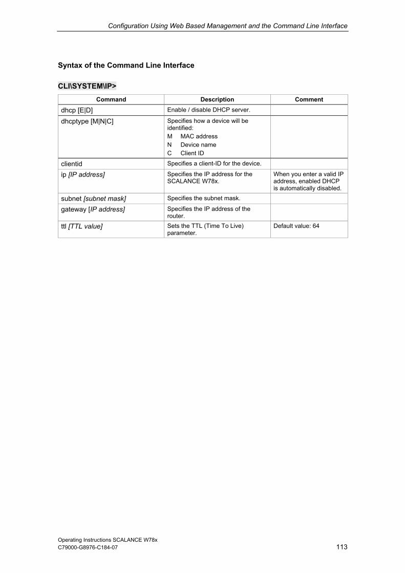
Configuration Using Web Based Management and the Command Line Interface
Syntax of the Command Line
113
Interface
CLI\SYSTEComment
M\IP> Command Description
dhcp [E|D] Enable / disable DHCP server.
dhcptype [M|N|C] Specifies how a device will be
M MAC address
C Client ID
identified:
N Device name
clientid Specifies a client-ID for the device.
ip [IP addre P
is automatically disabled.
ss] Specifies the IP address for the SCALANCE W78x.
When you enter a valid IPaddress, enabled DHC
subnet [subnet mask] Specifies the subnet mask.
gateway [IP address] Specifies the IP address of the router.
ttl [TTL value] Sets the TTL (Time To Live) parameter.
Default value: 64
Operating Instructions SCALANCE W78x C79000-G8976-C184-07

Configuration Using Web Based Management and the Command Line Interface
C79000-G8976-C184-07 114
6.2.3 Services Menu Command
Configuration
Here, you select the services with which access to the SCA 8x will be or example her d access is olcol is not p nd S
To improve security, you should only enable the services t
MP, it is possib to allo
SNMP. Following this, onfiguration of the SCAL ible.
LANCE W7possible. If, fwrite nor reaSNMP proto
, the SNMP Enabled check box is possible using the SNMP protoc
ermitted, it is not possible to se
not selected, neit (v1,v2c,v3). If the NMP traps.
hat you actually use.
Notice Over SN le to disable all services and
no further cw read access only over ANCE W78x is poss
If you only want to enable secure access over HTTPS whe ce, select the HTTPS only check box. If you want to enable the response of the device to Ping sig enabled check box.
tegrated SSH t to Telnet, the entire comm ing user authentica ncrypted.
Notes on WEB Enabled in the WEB Interface
he check box for the W selected and b Based Mana ger p
ess with H
If you want to deactivate the option of configuration with W ed Management, you can do this in the Security Wizard over Telnet and SNMP. Settings made using the Security Wizard only take effect after a restart on the SCALANCE W78x.
n configuring the devi
nals, select the Ping
With the in server, you have secure accessunication includ
o the CLI. In contrasttion is e
T EB Enabled entry is inactive because ossible configuration with We
option of accgement is no lon
TTP. without the
eb Bas
Operating Instructions SCALANCE W78x
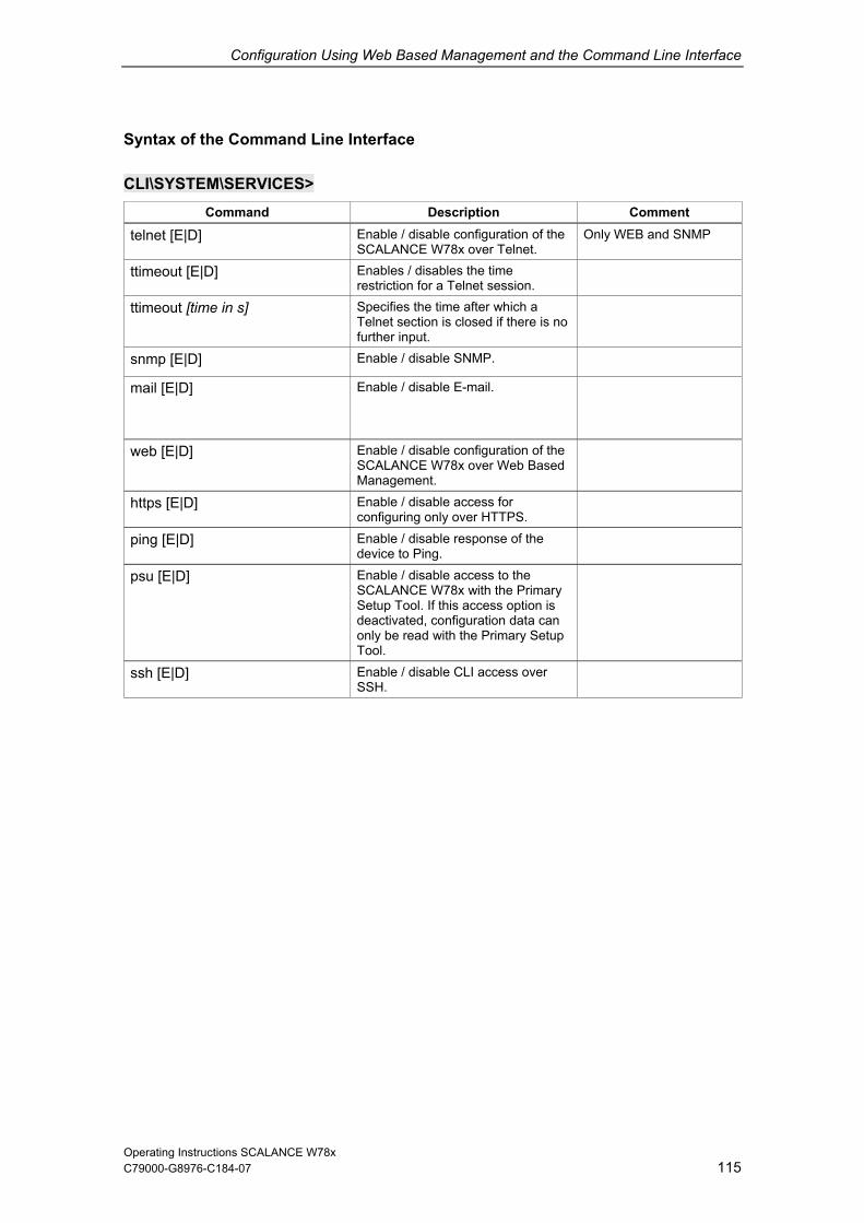
Configuration Using Web Based Management and the Command Line Interface
Syntax of the Command Line Interface
CLI\SYSTEM\SERVICES> Description Comment Command
telnet [E|D] Enable / disable configuration of the SCALANCE W78x over Telnet.
Only WEB and SNMP
ttimeout [E|D] Enables / disables the time restriction for a Telnet session.
ttimeout [tim Specifies the time after which a Telnet section is closed if there is no further input.
e in s]
snmp [E|D] Enable / disable SNMP.
mail [E|D] Enable / disable E-mail.
web [E|D] Enable / disable configuration of thSCALANCE W78x over Web Base
e d
Management.
https [E|D] ring only over HTTPS.
Enable / disable access for configu
ping [E|D] Enable / disable response of the device to Ping.
psu [E|D] Enable / disable access to the SCALANCE W78x with the Primary Setup Tool. If this access option is deactivated, configuration data can only be read with the Primary Setup Tool.
ssh [E|D] Enable / disable CLI access over SSH.
Operating Instructions SCALANCE W78x 115 C79000-G8976-C184-07

Configuration Using Web Based Management and the Command Line Interface
6.2.4 Restart Menu Command
C79000-G8976-C184-07 116
an leave the browser
estore M lts button
defaults) are not reset:
IP address
Subnet mask
SSID
address of the default router
System location
m contact
If you are logged on as user, the Restore Memory Defaults button is not visible.
Restart button
Click this button to restart the SCALANCE W78x. During a restart, the SCALANCE W78x is reinitialized, the internal firmware is reloaded, and the SCALANCE W78x runs a self-test. The entries that have been learned in the address table of the SCALANCE W78x are deleted. You cwindow open while the SCALANCE W78x restarts.
R emory Defau
Click this button to reset the configuration. The following parameters (protected
Gateway address
IP
DHCP flag
System name
Syste
Device mode
Country code
There is no automatic restart. This allows you to enter data using Web Based Management before the restart. The changes take effect only after a restart.
Operating Instructions SCALANCE W78x

Configuration Using Web Based Management and the Command Line Interface
C79000-G8976-C184-07 117
Restore Fa tory Defaults and Restart button
Click o restore the ion settings. Tdefaults (see above) are als is reinitialized and formatted if it exists. An automatic restart
Note
By resetting all the defaults, the IP address is also lost. Tthen only be accessed using lobtained over DHCP.
c
n this button to factory configurat he protected o reset. The C-PLUGis triggered.
he SCALANCE W78x can the Primary Setup Tool un ess the IP address is
If you are logged on as user, the Restore Factory Defaults button is not visible.
Syntax of the Command Line Interface
CLI\SYSTEDescription Comment
M\RESTARTS> Command
restart Restarts the SCALANCE W78x. The restart command can ,
however not using the shortcut commands.
be called from all menus
memreset Resets the factory settings and triggers a restart (the protected settings are not deleted).
defaults Resets the factory settings (the protected settings are also deleted).
Operating Instructions SCALANCE W78x

Configuration Using Web Based Management and the Command Line Interface
C79000-G8976-C184-07 118
d
System Ev
ge, you spec 78x reac s. You can configure the reaction of the SCALANCE W78x to the
Startup of the SCA
Change in the Ethe wn.
Error in authentication.
Changing the power supply of the SCALANCE W78x. nt is only useful when using a redundant power supply.
Change in the erro
If you use the SCALAN t, you nal
IP-Alive state chan ction
Link Check state ch e-specific connection monitoring)
Events related to bandwidth reservation iQoS
Authentication of the client
Detection of access points on own or an overlapping wireless channel.
Topology changes in Rapid Spanning Tree.
For the SCALANCE W788-1RR and SCALANCE W788-2RR models, events in conjunction with iPCF.
Events in conjunction with the Forced Roaming on IP down function .
Change in the WDS connection status Link up / Link down.
With the SCALANCE W788-2PRO and SCALANCE W788-2RR models, there is also the status of a redundant connection (redundant, not redundant, interrupted) as a system event.
6.2.5 Event Config Menu Comman
ents of the SCALANCE W78x
On this pa ify how the SCALANCE W ts to system eventfollowing events:
LANCE W78x
rnet status Link up / Link do
Evaluation of this eve
r status
CE W78x as an Access Poin can configure additiosystem events:
ge (application-specific conne
ange (devic
monitoring)
Operating Instructions SCALANCE W78x

Configuration Using Web Based Management and the Command Line Interface
C79000-G8976-C184-07 119
Reaction to System Events
es are possible:
The SCALANCE W
NCE W
The SCALANCE W .
The SCALANCE W r (the error LED lights up).
By selecting the approp , you specify which events trigger which actions on the SCALANCE W78x. With x in the d
or disa gge .
Syntax of the Command Line IFor each of the four po ap, log an ither E (Enabled, setting is ena ing is disa as the parameter. If, for example, an E- nt when t
rts (first parametetrap nor an error is gen d mus
setec CW E D E D
The following alternativ
The SCALA
78x sends an E-mail.
78x triggers an SNMP trap.
78x writes an entry in the log file
78x indicates an erro
riate check boxesrerow, you enable
the check boble the sending of E-mails or tri
Functions enablering of SNMP traps
nterface ssible reactions E-mail, tr d fault, ebled) or D (Disabled, sett
mail is sebled) must be entered
he SCALANCE W78x resta r "CW") and an entry is made in the
erated, the following comman log table but neither a t be entered:
CLI\SYSTEM\EVENT> Command Description Comment
setec CW <E|D> <E|D> <E|D> <E|D>
Reactions when the SCALANCE W78x restarts.
setec LU <E|D> <E|D> <E|D> <E|D>
Reaction to the Link Down event on the Ethernet interface.
If the error status was triggered only due to a link down event, the error states is cleared and the error LED goes off.
setec LD <E|D> <E|D> <E|D> <E|D>
Reaction to the Link Up event on the Ethernet interface.
setec AF <E|D> <E|D> <E|D> <E|D>
Reaction to a bad authentication over Web Based Management, CLI, or SNMP.
The SNMP trap AuthFault is sent only if there is a bad SNMP authentication.
setec PM <E|D> <E|D> <E|D> <E|D>
Reaction to a change of power supply over the M12 power connection.
setec PE <E|D> <E|D> <E|D> <E|D>
Reaction to a change of power supply over Ethernet.
setec FC <E|D> <E|D> <E|D> <E|D>
Reaction to a change in the error status.
setec AP <E|D> <E|D> <E|D> <E|D>
Reaction to detection of an access point on own or an overlapping wireless channel.
This command is not available in the client mode.
Operating Instructions SCALANCE W78x

Configuration Using Web Based Management and the Command Line Interface
C79000-G8976-C184-07 120
Command Description Comment
setec MS <E|D> <E|D> <E|D> <E|D>
Reaction when the update time in iPCF mode with PNIO support cannot be k n
This command is available only on the SCALA 1RR
in
ept to due to aadditional client.
NCE W788-and SCALANCE W788-2RR models but notclient mode.
setec CT <E|D> <E <E|D> <E|
|D> D> he
SCALANCE W788-1RR and SCALANCE W788-2RR models but not in client mode.
Reaction when the specified update time in iPCF mode with PNIO support cannot be kept to.
This command is available only on t
setec IS <E|D <E|D> <E|D>
> <E|D>
the connection status hanges, an event is
triggered. If the connection no longer exists, the error state is triggered and the error ED is lit. his command is not
available in the client mode.
Reaction to a change in the connection status on a client for which the IP-alive monitoring is activated.
Ifc
LT
setec LI <E|D> <E|D> <E|D> <E|D> connection monitored with the Link
Check function.
his command is not available in the client mode.
Reaction when establishing a T
setec IQ <E|D> <E|D> <E|D>
Reaction to a change in the iQoS status.
This command is not availabl t <E|D> e in the clienmode.
setec CA <E|D> <E|D> <E|D> authentication status.
Reaction to a change in the client This command is not available in the client mode.
setec RD <E|D> <E <E|D> <E|D>
|D> his command is not available in the client mode.
Reaction to a change in the redundancy event status.
T
Operating Instructions SCALANCE W78x

Configuration Using Web Based Management and the Command Line Interface
C79000-G8976-C184-07 121
mand
Sender an
78x sends an E-mail to as a reaction to configured events. You can also enter a sender. This allows you to recognize
ALANCE W78x uses the following sender: SCALANCE_W@<IP address>
Syntax of the Command Line Interface
6.2.6 E-mail Config Menu Com
d Recipient of an E-mail
Here, you specify who the SCALANCE W
which device is involved and sent the E-mail. If you do not make an entry in the From box, the SC
CLI\SYSTECommand Description Comment
M\EMAIL>
mail [E|D] Enable/disable the E-mail service
email [E-ma es d
il address] Specifies the address(es) to which the SCALANCE W78x sense E-mails.
Several E-mail addresscan be entered separateby semicolons.
smtp <IP ad [:port nu
dress> mber]
Specifies the IP address and the port number of the SMTP server.
from [text for sender field] Specifies the sender of E-mails from SCALANCE W78x.
Operating Instructions SCALANCE W78x

Configuration Using Web Based Management and the Command Line Interface
C79000-G8976-C184-07 122
d
Configurati
Select the check boxes the SNMP functionality you want to use. SNMP version 3 ssions to be assigned and protocol level,
n, and enc nd usUsers submenus. You entries there if the
Pv3 enabled chec e
Notice When using SNMP ver uld disable SNMP V1 and V2c because the
curity settings of SNMP V3 can be bypassed by access over SNMP V1 or V2c.
6.2.7 SNMP Config Menu Comman
on
of the entries according to allows permi
authenticatio ryption. You specify groups acan also make
ers in the Groups and
SNM k box is not selected, however the ntries are not applied.
sion 3, you shose
Trap Submenu
Here, you enter the IP addresses of up to 10 trap receivers. The SCALANCE W78x sends a trap to all the addresses you enter if their Enable trap check boxes are selected.
Note
During a warm or cold restart with a wireless connection ( AP client, WDS, or WRED), there is no guarantee that the recipient can be reached at the time when the trap is sent. This leads to a loss of the message.
Groups Submenu
This page displays the SNMPv3 groups. You can create a new group by clicking the New button and specifying the group name, the security level, and the write or read permissions.
You can delete a group by selecting the check box in the Del column and clicking the Set Values button. If members are already entered in the group, you cannot delete the group nor is it possible to change the security level of the group.
Operating Instructions SCALANCE W78x

Configuration Using Web Based Management and the Command Line Interface
There are three SNMPv3 security levels:
C79000-G8976-C184-07 123
Security Level Special Features Comment
None No authentication, no encryption.
Auth/No Priv Authentication with the MD5 To display the members of
rs).
or SHA algorithm, no encryption.
the group, you must enter the authentication password (maximum of 63 characte
encryption with the DES3 algorithm.
the group, you must enter the authentication password (maximum of 63 characters).
Auth/Priv Authentication with the MD5 or SHA algorithm,
To display the members of
Users Submenu
This page displays the SNMPv3 u create a new use the ton and specify oup to which the user will
belong. If necessary, yo nter the passwords for the authentication and the encryption.
You can delete a user b Del column and clicking the Set Values button.
sers. You can r by clickingNew but ing the user name and the gr
u must also efor
y selecting the check box in the
Operating Instructions SCALANCE W78x

Configuration Using Web Based Management and the Command Line Interface
Syntax of the Command Line Interface
CLI\SYSTEM\SNMP> Description Comment Command
snmp [E|D] Pv1, v2c, v3 and
Enables / disables SNMP. Enables / disables SNMTraps.
snmpv1 [E|D] Enables / disables SNMPv1/v2c. Enables / disables SNMPv1, v2c and traps.
snmpv3 [E| Enables / di 3. The spe of D] sables SNMPv cial featuresSNMPv3 undertake effect after you disable SNMPv1. Enabling SNMPv3 does not automatically disable SNMPv1.
snmpro [E|D] Enables / disables SNMPv1/v2c read only.
getcomm [Read community string] 3
characters.
Specifies the Read community string, maximum length 6
The default is public.
setcomm [Write community string]
Specifies the Write community string, maximum length 63 characters.
The default is private.
traps [E|D] Enables / disables SNMPv1 traps. also
Traps are then enabled, if SNMP v1, v2c is enabled.
Operating Instructions SCALANCE W78x 124 C79000-G8976-C184-07

Configuration Using Web Based Management and the Command Line Interface
C79000-G8976-C184-07 125
CLI\SYSTEM\SNMP\GROUP> scription Comment Command De
add <Name> [NOAUTH|AUTH|PRIV]
Adds an SNMPv3 group. NOAUTH – No authentication, no encryption;
H - Authentication with MD5 or algorithm, no encryption.
Write access without read access is not possible.
[R|W] AUTSHAPRIV - Authentication with MD5 or SHA algorithm and encryption with the DES3 algorithm. R – Read access; W - Write access
edit <Index [NOAUTH|AUTH|PRIV] [RE|RD|
y level of the hts.
ws write access; es write access;
You cannot edit the authentication and encryption settings unless the group is empty. Preventing read access also prevents write access. Permitting write access also permits read access.
> Changes the securitgroup and sets the access rig
WE|WD] You can view of the index of the group with the "info“ command. RE – allows read access; RD – denies read access; WE – alloWD – deni
delete <Ind roup from the ition.
Is only possible to delete a group if it is empty.
ex> Deletes the SNMPv3 ggroup list at the index pos
clearall at are Clears all SNMP groups thempty.
Operating Instructions SCALANCE W78x

Configuration Using Web Based Management and the Command Line Interface
C79000-G8976-C184-07 126
CLI\SYSTEscription Comment
M\SNMP\USER> Command De
add <user n[NONE|MD[authentica[Encryption ] group, the algorithm must be
specified as a parameter (MD5 or
must be specified as a parameter.
entication
n be a maximum of 63 characters long.
ame> <group name> Assigns an SNMPv3 user to a group.
The authpassword an5|SHA]
tion ID]
If authentication is necessary for the d the
encryption password ca ID
SHA). If encryption is necessary for the group, the encryption password
edit <index <group n [NONE|M[authentica[Encryption ID]
> ame> D5|SHA]
tion ID]
Changes the group assignment, the authentication algorithm, and the encryption password of the SNMPv3 user.
delete <Index> Deletes an SNMPv3 user from the list at the point identified by the index.
clearall Deletes all SNMPv3 users.
CLI\SYSTEM\SNMP\TRAP> Command Description Comment
traps [E|D] Traps are then enabled, if SNMP v1, v2c is also enabled.
Enables / disables SNMP traps.
settrap <entry> Specifies the IP addrerecipient entry (entry <IP address>
<E|D>
ss of the trap between 1 and
10) and enables / disables the sending of traps to this recipient.
Operating Instructions SCALANCE W78x

Configuration Using Web Based Management and the Command Line Interface
C79000-G8976-C184-07 127
6.2.8 Sy
Sy sed for transferring short, unencrypted text messages in the IP network. This requires a standard Syslog server.
Syslog Configuration w
sed for the Syslog protocol are displayed and set in the System -
slog Menu Command
slog according to RFC 3164 is u
ith the SCALANCE W
The parameters u> Syslog menu:
Operating Instructions SCALANCE W78x

Configuration Using Web Based Management and the Command Line Interface
C79000-G8976-C184-07 128
of the parameters is a
S box:
The server address dec slosent. If no IP address is box, no Syslog messages are sent. If the Syslog server is not in CE Wattempt is made to establi
log table check box:
This check box decides de in the log table are also sent as ssages.
uth log ch
also
The meaning s follows:
yslog Server text
ides the IP address to which the Sy entered in this
g messages are
the same network as the SCALANault gateway.
, an automatic sh a connection over the def
whether all entries maSyslog me
a eck box:
This check box decides whether all entries made in the authentication log aresent as Syslog messages.
Operating Instructions SCALANCE W78x

Configuration Using Web Based Management and the Command Line Interface
Syntax of the Command Line Interfac
129
e
CLI\SYSTEM\SYSLOG> Command Description Comment
info Displays the current Syslog configuration.
server [IP th Admin rights.
address] Specifies the IP address of the Syslog server.
Can only be changed wi
logs [ D | E ] Specifies whether the log entries are Can only be changed with also sent to the Syslog server. Admin rights.
auths [ D log entries are also sent to the Syslog server.
ged with Admin rights.
| E ] Specifies whether the authentication Can only be chan
Operating Instructions SCALANCE W78x C79000-G8976-C184-07
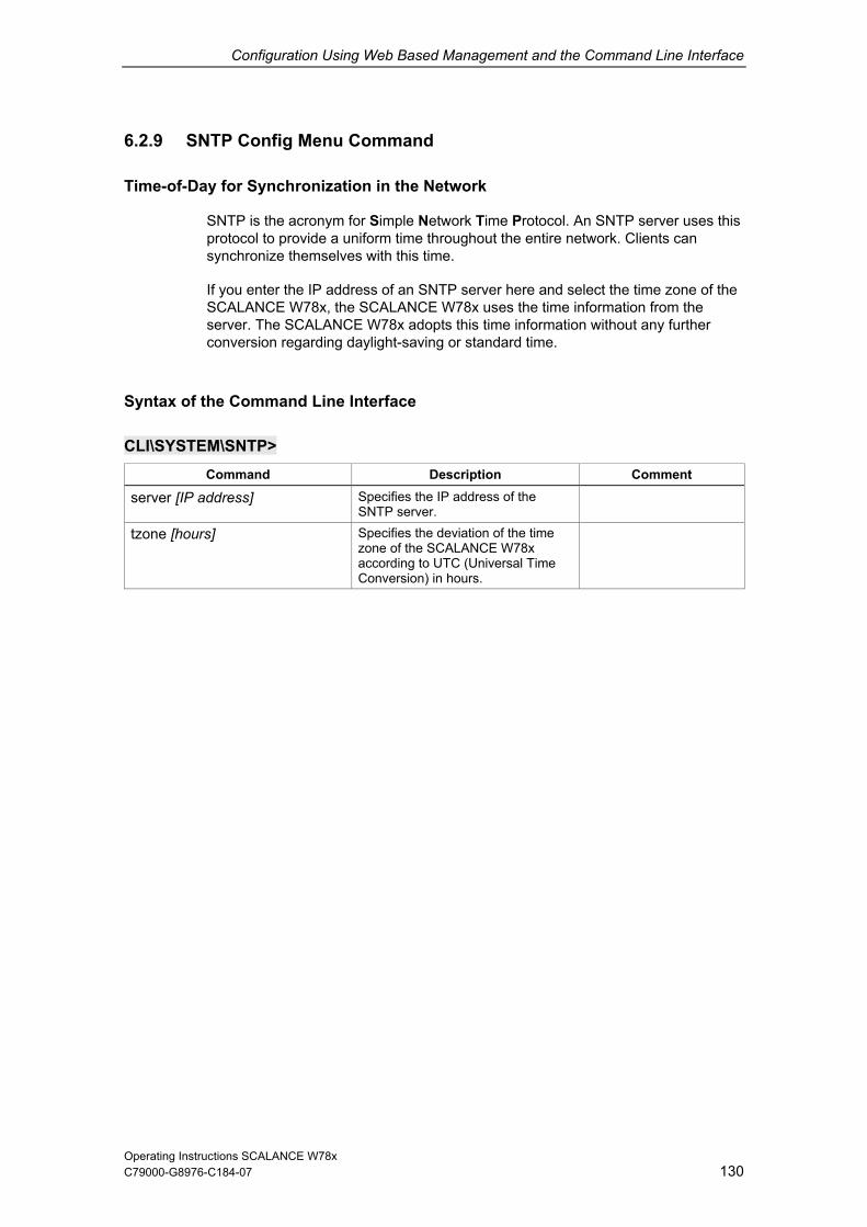
Configuration Using Web Based Management and the Command Line Interface
C79000-G8976-C184-07 130
6.2.9 SNTP Config Menu Command
Time-of-Day for Sy
SNTP ol. An SNTP server uses this protocol t tire network. Clients can synch th this time.
If you enter the IP addre ere and select the time zone of the E W78x uses the time information from the
s this time information without any further conve
Syntax of the Command Line Interface
nchronization in the Network
is the acronym for Simple Network Time Protoco provide a uniform time throughout the en
ronize themselves wi
ss of an SNTP server hSCALANCE W78x, the SCALANCserver. The SCALANCE W78x adopt
rsion regarding daylight-saving or standard time.
CLI\SYSTEM\SNTescription Comment
P> Command D
server [IP address] Specifies the IP address of the SNTP server.
tzone [hours]
Conversion) in hours.
Specifies the deviation of the time zone of the SCALANCE W78x according to UTC (Universal Time
Operating Instructions SCALANCE W78x

Configuration Using Web Based Management and the Command Line Interface
C79000-G8976-C184-07 131
6.2.10 Fault State Menu Command
Information on E
This page displays information on faults/errors that have occurred. You can delete this in m e button.
rrors/Faults
for ation if you click on the Remove Fault Stat
CLI\SYSTEM\FAULCommand
T> Description Comment
fault [OFF] with
: "fault OFF“. Ideally, however, the cause of the problem
be eliminated.
Display the fault status and cause of the fault.
You can reset the LEDand the fault statusthe command
should
ipacknow [Index|All]
s
messages have been acknowledged. The fault
he Fault LED
error message. The command is not visible in the client mode.
Displays or acknowledges (clears) the IP Alive messages requiring acknowledgment.
The fault state remainactive until all the fault
state and tare cleared if the only reason was an IP Alive
linkack [Index|All] ges requiring active until all the fault
state and the Fault LED are cleared if the only reason was a Link Check error message. The command is not visible in the client mode.
Displays or acknowledges (clears) the Link Check messa
The fault state remains
acknowledgment. messages have been acknowledged. The fault
Operating Instructions SCALANCE W78x

Configuration Using Web Based Management and the Command Line Interface
C79000-G8976-C184-07 132
6.2.11 Lo
Saving and o
Clickin ns a page with the current firmware version. The HTTP and TFTP submenus allow you to save device data in external files or to transfer data from external files to the SCALANCE W78x. If the device is operated with a C-PLUG, the data from the loaded configuration file is
s the C-PLUG is inserted, the device works with
device data in external files:
figuration data of the SCALANCE W78x
the content of the l
the firmware of the
nt certificate
the server certificat
You can transfer the fo al files to th 8x:
the configuration data of the SCALANCE W78x
the firmware of the SCALANCE W78x
the client certificate (only in client mode)
the server certificat
For information on cert m Manual Basics of Industrial Wireless LAN
Note
When you download th LANCE W78x, a restart is performed so that the n he restart takes place automatically during the loa The device can no longer be reached using the old I configuration data contains a new IP address.
ad & Save Menu Command
L ading Device Data
g the Load & Save menu command first ope
stored on the C-PLUG. As long athe configuration on the C-PLUG.
You can save the following
the con
og table
SCALANCE W78x
the clie (only in client mode)
e (only in client mode)
llowing data from extern e SCALANCE W7
e (only in client mode)
ificates, please refer to the Syste.
e configuration data to a SCAew data is adopted correctly. T
ding of HTTP and TFTP.P address if the downloaded
Operating Instructions SCALANCE W78x

Configuration Using Web Based Management and the Command Line Interface
Note
C79000-G8976-C184-07 133
As of firmware version V3.0, the file with the configuration data of the AP also includes the following information
Version of the configuration file •
Configuration files generated with a device with firmware version V2.4 or older, can e loaded on devices with firmware version V3.0 without causing problems.
uration files generated with a device with firmware version V3.0, cannot, version V2.4 or older.
• Firmware version with which this configuration file was created • Order number (MLFB) of the device with which the configuration file was
created It is necessary that the configuration on the C-PLUG was generated with a firmware version ≤ the firmware version on the destination device. Example:
bConfighowever, be loaded on devices with firmware
Reusing Configuration Data
ata reduces the effort if several SCALANCE W78x devices have the same configuration and when IP addresses are obtained
figuration data on a PC after you have configured a load this file to all other SCALANCE W78x devices you
How to Lo r HTTP / HTTPS
data .
lternative, you can also use a file selection dialog that opens after you click the Browse... button.
clicking the Save button. Start the load from file ction by clicking the Load button.
How to Load or Save Data over TFTP
1 Enter the IP address of the TFTP server in the TFTP Server IP text box.
2. Enter the port of the TFTP server in the Port text box in the default value does not meet your requirements.
3. Click on the Set Values button before you enter any further information for saving the data.
Saving and reading in configuration d
over DHCP. Save the conSCALANCE W78x. Downwant to configure. If necessary, you may need to assign an IP address to this SCALANCE W78x first using the Primary Setup Tool.
ad or Save Data ove
1. Specify the name of the file from which the data will be taken or where thewill be saved in the relevant text box for the configuration data or firmwareAs an a
2 Start the save function by fun
Operating Instructions SCALANCE W78x

Configuration Using Web Based Management and the Command Line Interface
C79000-G8976-C184-07 134
aximum 32 characters) from which the data will be taken or where the data will be saved in the relevant text box for the
firmware.
save function by click utton. Start the load from file clicking
Configuration Package
If security certificates fo nstalled on a client, when the configuration is saved, ie n of saving the configuration file
rtificates as a he aid of the configuration kage, clients can be s, identical settings AND
certificates are transfer st as when you download the configuration file, this is followed ecial measures are necessary when downloading the configuration because the SCALANCE W automatically recognizes the type of configuration file. As a result, it is only possible to assign one common name for the configuration file or configuration package.
Syntax of the Command Line Interface
4. Specify the name of the file (m
configuration data or
5 Start the ing the Save bfunction by the Load button.
r the client and/or server are ithe cl nt provides the optio
with the cepac
configuration package. With t replicated simply; in other word
red to the clients in one step. Juby a restart. No sp
CLI\SYSTEM\LOADSAVE> Command Description Comment
fwname [file name] Specifies the name of a file from which the firmware will be loaded or in which the firmware will be saved. This name can be a maximum of 32 characters long.
fwload Loads the firmware from a file.
fwsave Saves the firmware in a file.
cfgname [file name] Specifies the name of a file from which the configuration data will be loaded or in which the configuration data will be saved.
cfgload Loads the configuration / configuration package from a file.
cfgsave Saves the configuration data in a file.
logname [file name] Specifies the name of a file in which the log table will be saved.
logsave Saves the log table in a file.
server [IP address]:[port number]
Specifies the IP address and the port of the TFTP server.
cltcert <certificate> Specifies the name of the certificate for the client.
In client mode only.
cltpass <password> Authorizes use of the certificate, In client mode only.
cltload Downloads the client certificate from a file.
In client mode only.
Operating Instructions SCALANCE W78x

Configuration Using Web Based Management and the Command Line Interface
135
Description Comment Command
cltsave Saves the client certificate in a file. In client mode only.
srvcert <certificate> Specifies the name of the certificate for the server.
In client mode only.
srvload e from a In client mode only. Downloads a server certificatfile.
srvsave Saves the server certificate in a file. In client mode only.
cltdel Deletes the client certificate. In client mode only.
srvdel Deletes the server certificate. In client mode only.
pkgsave Saves the Configuration Package in a file over a TFTP server.
In client mode only.
The functionality can be controlled over SNMP with the OID Note
1.3.6.1.4.1.4196.1.1.4.100.1.5.1.19 (snDownloadEcmCfgPackageControl). Working with this function is analogous to working with the other OIDs in this group.
Operating Instructions SCALANCE W78x C79000-G8976-C184-07

Configuration Using Web Based Management and the Command Line Interface
C79000-G8976-C184-07 136
6.2.12 C-PLUG Menu Command
Information on the Content of the C-PLUG
iscanis st tarts up with the
hanges to parameters are stored on the C-PLU
Therest UG> function.
Th menu command provides you with detailed information on the C-PLUG. You also format the C-PLUG or provide it with new content. As soon as the device arted with a C-PLUG inserted, the SCALANCE W s
configuration data on the C-PLUG. CG and displayed over the Web and CLI.
data in the memory of the device only becomes accessible when the device arts without a C-PLUG using the <Restart without C-PL
C-PLUG State text box
This displays the status of the C-PLUG. The following are possible:
ACCEPTED A C-PLUG with a valid and suitable content is inserted in the device.
Operating Instructions SCALANCE W78x

Configuration Using Web Based Management and the Command Line Interface
C79000-G8976-C184-07 137
C-PLUG missing or invalid or incompatible content of an inserted C-
PRESENT
Indicates the device type within the product line that used the C-PLUG in
e
nge if you add or remove modules or extenders, it can,
Displays the type of file system on the C-PLUG.
ystem Size text box
.
tring text box
Here, you will see all the additional information about the device that used order number, type
oftware.
NOT ACCEPTED
PLUG. The status is also displayed when the C-PLUG was formatted during operation.
NOT ACCEPTED, HEADER CRC ERROR A C-PLUG with a bad content is inserted.
NOTNo C-PLUG is inserted in the device.
C-PLUG Device Group text box
Indicates the SIMATIC net product line that used the C-PLUG in previous operation.
C-PLUG Device Type text box
previous operation.
Configuration Revision text box
The version of the configuration structure. This information relates to the configuration options supported by the device and has nothing to do with thconcrete hardware configuration. This revision information does not therefore chahowever, change if you update the firmware.
File System text box
File S
Displays the maximum storage capacity of the file system on the C-PLUG
File System Usage text box
Displays the memory utilization of the file system of the C-PLUG.
C-PLUG Info S
the C-PLUG during previous operation, for example, designation, and the versions of the hardware and s
Operating Instructions SCALANCE W78x
Configuration Using Web Based Management and the Command Line Interface
C79000-G8976-C184-07 138
Modify C-PLUG list box, Modify button
ou are logged on as administrator.
nal Configuration to C-PLUG The configuration in the internal flash memory of the switch is copied to the C-PLUG; this is followed by a restart. There is one important use case for this function: The device has started up with a C-PLUG containing a bad configuration or a configuration different from the device. If you have not yet made any configuration changes after starting up the device, you can use this function to overwrite the content of the C-PLUG with the original device configuration.
Load default Configuration to C-PLUG and Restart A configuration with all the factory default values is stored on the C-PLUG. This is followed by a restart in which the SCALANCE W78x starts up with these default values.
Clean C-PLUG (Low Level Format, Configuration lost) Deletes all data on the C-PLUG and starts a low-level formatting function. There is no automatic restart.
Create PRESET PLUG Writes configuration data to a PRESET PLUG. For detailed information on this topic, refer to Section 3.4
After making your selection, start the function by clicking the Modify button.
You can only make settings in this box if yHere, you decide how you want to change the content of the C-PLUG. The following alternatives are possible:
Copy inter
Operating Instructions SCALANCE W78x

Configuration Using Web Based Management and the Command Line Interface
C79000-G8976-C184-07 139
78x detects a C-PLUG error during startup, a message is ased Management. C-PLUG errors can have two causes:
or a different device type.
C-PLUG in the SCALANCE ugh a C-PL sent the last shutdown of th
C-PLUG Error Message
If the SCALANCE Wdisplayed by Web B
The C-PLUG contains bad data or data f
There is no prior to
W78x althoe device.
UG was pre
Operating Instructions SCALANCE W78x

Configuration Using Web Based Management and the Command Line Interface
C79000-G8976-C184-07 140
Syntax of the Command Line Interface
CLI\SYSTEM\CPLUG> Command Description ment Com
initdef Reinitializes the C-PLUG and copies the default configuration to it.
ed. All information is delet
initmem G and copies the configuration currently stored
ed. Reinitializes the C-PLU
internally to it.
All information is delet
bootfrom [MEMORY] Displays the source medium from is currently MEMORY.
The restart is performed automatically.
G was
n must be read from internal memory. If a C-PLUG is inserted, the system or as attempts to read the configuration from it. The bootfrom [MEMORY] command then has no effect.
which the configurationbeing read: C-PLUG or
If the C-PLUremoved, you must specify that the configuratio
preplug <dev> Writes configuration data to a PRESET PLUG. The index parameter specifies the device for which the PRESET PLUG will be suitable: 1 SCALANCE W788-1PRO 2 SCALANCE W788-2PRO 3 SCALANCE W788-1RR 4 SCALANCE W788-2RR 5 SCALANCE W744-1PRO 6 SCALANCE W746-1 PRO 7 SCALANCE W747-1RR 8 IWLAN/PB Link
Operating Instructions SCALANCE W78x

Configuration Using Web Based Management and the Command Line Interface
6.3 Interfaces Menu
C79000-G8976-C184-07 141
interface.
With the menu command Interfaces > WLAN1…2 > Virtual AP count in the Access ode, you can also configure up to eight virtual access points (VAP0 …
s interface.
Introduction
The SCALANCE W78x has one Ethernet interface and up to two WLAN interfaces that can be configured separately. In the pages of this menu, you can configureboth the wired Ethernet interface and the WLAN
Point mVAP7) per wireles
Note VAPs are visible only after an AP count > 0.
6.3.1 Ethernet Menu Command
Transmission Speed and Mode
thernet connection. When you select the entry Auto in the Speed / Mode list box, the SCALANCE W78x sets a suitable
n the other network nodes and crosses over the
ings on the partner device.
For a wired Ethernet interface, you only to specify the transmission speed / mode parameters and the crossing over of the E
speed and mode depending oEthernet connection.
If you select an entry other than Auto in the Speed / Mode list box, you must specify the crossing over of the Ethernet connection manually with Ethernet crossing.
Note If you specify the mode, you must make the same sett
Operating Instructions SCALANCE W78x

Configuration Using Web Based Management and the Command Line Interface
Syntax of the Co
C79000-G8976-C184-07 142
mmand Line Interface
CLI\INTERFACES\ETHERNET> Command Description Comment
ethspeed [A 10F|1
ic selection by the SCALANCE W788 100F 100 Mbps full duplex 100H 100 Mbps half duplex 10F 10 Mbps full duplex
|100F|100H| 0H]
Specifies the transmission speed and mode of the Ethernet interface: A automat
10H 10 Mbps half duplex
ethcross [E|D] Manual selection of Ethernet interface crossover. Possible only when ethspeed is not set to auto.
Operating Instructions SCALANCE W78x

Configuration Using Web Based Management and the Command Line Interface
C79000-G8976-C184-07 143
6.3.2 W
Enabling t
Network n ly in access point mode)
nter the network name of the wireless network in the SSID text box. If you have he Basic Wizard, a value is already entered here.
Infrastruct
Select Infrastructure to connect to an access point. Ad hoc is used to connect clients with each other without an access point. This is only possible when ad hoc is set on all clients.
Transmiss
SpeBas
Not
It is not possible to select the 802.11h protocol in all country settings. It is specified
the comm s active for this country code appears behind the Enable
rior
f signals from a primary user (for example dar).
LAN Menu Command
he Interface
Enabling interface by selecting Enable Interface.
ame (on
Eused t
ure / Ad Hoc (only in client mode)
ion Mode
cify the transmission mode in the Wireless Mode list box. If you have used the ic Wizard, a value is already entered here.
e IEEE 802.11h transmission (only in Access Point mode):
by the configuration of Country code on the System page. If the 802.11h protocol is selected, after applying the configuration with Set Values,
ent (DFS iInterface check box. With the automatically enabled Dynamic Frequency Selection function (DFS), pto communication, the access point checks whether configured or selected channel (see Auto Channel Select) is free ora
Operating Instructions SCALANCE W78x

Configuration Using Web Based Management and the Command Line Interface
C79000-G8976-C184-07 144
If signals of a primary user are found on the configured or selected channel, the access point follows the procedure outlined below:
Auto channel select = enabled With automatic channel select, the access point changes to a different channel and repeats the availability check for this channel.
Auto channel select = disabled If the channel is fixed in the configuration, the access point changes to the configured alternative channel and repeats the availability check for this channel. If a primary user (for example radar) is discovered on the alternative channel, a further channel is selected at random.
Communication with clients is started only when no primary user has been discovered on the selected channel for one minute.
Outdoor AP mode (Access Point mode) / Outdoor Client mode (Client mode)
ndoor or outdoor AP mode. t permitted channels and transmit
Channel S
check box if you want the SCALANCE W78x to re
nel
nnel in case signals of a primary user are found on the main channel.
Make sure that the alternative channel is not being used by other access points.
In the IEEE 802.11h transmission mode, it is not practical to select the WDS mode at the same time. In WDS mode, all SCALANCE W78x devices must use the same channel. If a signal from a primary user is detected by an AP, the channel is changed automatically and the existing connection is then terminated.
The SCALANCE W78x can be operated either in the iIn indoor AP mode, all the country-dependenpower settings are available for operation in a building. In outdoor AP mode, the selection of country-dependent channels and the transmit power for operation are restricted for outdoor use. If the SCALANCE W is operated outdoors, make sure that the device is not exposed to rain (installed under a roof) and is not exposed to direct sunlight (installed with UV protection). You enable this mode by selecting Outdoor AP mode.
election
Select the Auto Channel Selectsearch for a free channel itself. If you want to specify a specific channel, make suthat Auto Channel Select is not selected. You can specify a suitable channel in the Radio Channel list box.
Auto Channel Select does not exist in the client mode. You can only set a chanin the ad hoc mode.
IEEE 802.11h transmission: If you have selected the 802.11h protocol for transmission in access point mode and Auto Channel Select is not selected, the Alt. radio channel input box is displayed below Radio channel. Here, you can select the alternative cha
Operating Instructions SCALANCE W78x

Configuration Using Web Based Management and the Command Line Interface
C79000-G8976-C184-07 145
ort of
done
As long as the client is waiting for an Ethernet frame, it registers with the access point using its own MAC address. As soon as the first Ethernet frame is received,
point and immediately registers again with ame. If there is now a link-down on the
h
devices are connected to the client, you should not select this setting.
e d enter the MAC
To be able to of devices downstream from the client, A t b member that only layer 3 connectiopossible (TCP/IP).
If up to eight MAC addre he client, the layer 2 tunneling setting ANCE W746-1PRO and S R
N
The layer 2 tunneling fun ss points as of firmware ve equirements of in s in ith s l de froconnect to standard Wi- SCALANCE W access points with firmware V3.0 or older.
MAC Address of the Client (only in client mode)
A MAC address must be specified for the devices connected to the Ethernet pthe SCALANCE W74x client before it can be reached. This MAC address is usedby the client for wireless communication with the access point. This can beautomatically by the client adopting the MAC address of the first frame that it receives over the Ethernet interface. If this is required, Auto find Adopt MAC must be selected.
the client deregisters from the accessthe MAC address from the Ethernet frEthernet port, the client deregisters from the access point and registers again witits own MAC address.
If several
You also have the option of specifying the MAC address of the connected devicmanually. To use this option, select Set 'Adopt MAC' manually anaddress of the device connected to the client in the Adopt MAC text box.
address an edopt own MAC mus
ntire network e selected. Re ns are
sses need to be served downstream from t must be selected for SCAL
CALANCE W747-1R .
ote ctionality is supported by SCALANCE W 788 acce
rsion V3.1. This setting meets the rdustrial applicationvices downstream
which MAC address-based communication wm the client is required. Clients with this setting canFi devices and
everanot
Virtual AP count (only in access point mode of a W788xRR)
If you want to configure virtual access points (VAPs) on this AP, set the number of virtual access points using the Virtual AP count list box. If Virtual AP count = 0 and VLAN/Prio Tag is disabled, no VAPs are created.
You can define up to a maximum of 8 VAPs. The settings of VAP0 are made directly in Interfaces/WLAN, the settings for VAP1...7 can be found in the Interfaces/WLAN/VAP1...7 submenus.
By using virtual access points, various SSIDs (maximum of 8 per WLAN interface) can be configured with different security settings. You can assign each virtual AP to a particular VLAN.
Operating Instructions SCALANCE W78x

Configuration Using Web Based Management and the Command Line Interface
C79000-G8976-C184-07 146
Set Values.
configured virtual acce rtual AP count > 0) point will be reque CALA CE W
icking Set Values.
Set values
Apply the configuration by clicking
If you haveode, you
ss points (Vi , in access 78x after m
clsted to run a restart on the S N
Operating Instructions SCALANCE W78x

Configuration Using Web Based Management and the Command Line Interface
C79000-G8976-C184-07 147
Syntax of the Command Line Interface
CLI\INTERFACES\WLAN1>
or for the second wireless adapter (if it exists) C S\WLAN2>
mmand
LI\INTERFACECo Description Comment
port [E|D] able wireless port. Enable / dis
ssid [network name] Assigns a network name (SSID). Available only in the access point mode.
mode [A|B|G|H|T|U|X] Selects the transmission standard: A 802.11a B 802.11b G 802.11g H 802.11h T 802.11a Turbo U 802.11h Turbo X 802.11g Turbo
Depending on the countrycode, some settings are not possible and will then be rejected.
802.11a Turbo cannot be set in all countries.
autoch [E|D] able the channel ALANCE W78x.
Available only in the Enable / disselection by the SC access point mode.
channel [1...167] channel. Specifies the wireless
altchan [channel] er of the nnel.
11h Enters the channel numbalternative DFS cha
Possible only in 802.transmission.
adopt [MAC address] e vailable only in the client ode.
MAC address of the devicconnected to the client over Ethernet.
Am
autoadopt [E|D|OWN|L2T] MAC nnected to
rnet. The OWN parameter means that the client registers with the access point with its own Ethernet MAC address. With this setting, however, only IP data traffic is possible.
vailable only in the client ode.
Automatic adoption of theaddress of the device cothe client over Ethe
Am
adhoc [E|D] Select ad hoc or infrastructure mode.
Available only in the client mode.
anyssid [E|D] With ANY SSID, the client connects to the best access point in the environment in which it is permitted to connect.
Available only in the client mode.
vapno [0...7] Specifies the number of virtual access points
outdoor [E|D] Enable / disable outdoor AP mode
802.11 g Open the ADVANCED G (802.11g) menu
ADVANCED Open the ADVANCED menu
DATARATES Open the DATARATES menu
VAP1 Open the VAP1 menu Displayed only when vapno > 0.
Operating Instructions SCALANCE W78x

Configuration Using Web Based Management and the Command Line Interface
148
Comment Command Description
VAP2 Open the VAP2 menu Displayed only when vapno > 1.
VAP3 Open the VAP3 menu Displayed only when vapno > 2.
VAP4 vapno > 3.
Open the VAP4 menu Displayed only when
VAP5 Open the VAP5 menu Displayed only when vapno > 4.
VAP6 Open the VAP6 menu Displayed only when vapno > 5.
VAP7 Open the VAP7 menu Displayed only when vapno > 6.
Operating Instructions SCALANCE W78x C79000-G8976-C184-07

Configuration Using Web Based Management and the Command Line Interface
6.3.3 Advanced Submenu
C79000-G8976-C184-07 149
Configurin
you can s cneed to adapt the para ge if the SCALANC x cannot be
ed as it is intended w
Transmit Power
In the Transmit Power list box, you can specify the output power of the SCALANCE W78x. It may be necessary to reduce the transmit power when using antennas to avoid exceeding the maximum legal transmit power. Reducing the
educes cell size.
at
de The Beacon Rate list box specifies the data rate of beacons. The higher the data rate, the shorter the transmission range.
s
ng vironments). The value 5 would mean that the SCALANCE
W78x collects the broadcast and multicast packets and sends them after every fifth beacon. Increasing this value allows a longer sleep mode for the clients but means a greater delay for broadcast and multicast packets.
RTS/CTS
RTS/CTS (Request To Send/Clear To Send) is a method for avoiding collisions based on the exchange of status information before sending the actual data (Hidden node problem). To minimize network load resulting from the additional protocol exchange, this method is used only when a packet size that you select with the RTS/CTS Threshold is exceeded.
g Transmission Characteristics
On this page, pecify details of the transmissionmeters on this pa
haracteristics. You only E W78
us ith the default settings.
transmit power effectively r
Beacons
Beacons are packets that are sent cyclically by a SCALANCE W78x to inform clients of its existence. In the Beacon Interval text box, you specify the interval which the SCALANCE W78x sends beacons.
Only in the access point mode and with the client in the ad hoc mo
Only in access point mode The Data Beacon Rate DTIM (Delivery Traffic Indication Map) parameter specifiehow often the SCALANCE W78x sends broadcast and multicast packets over the wireless interface. If you enter 1 in this box, the SCALANCE W78x transmits broadcast and multicast packets directly after each beacon (recommended settifor normal network en
Operating Instructions SCALANCE W78x

Configuration Using Web Based Management and the Command Line Interface
C79000-G8976-C184-07 150
kage
bled into the original size after they have
re difficult to transmit. However fragmentation into smaller roughput.
Repetition
is
t immediately. The number of attempted repetitions is specified with the HW Retry number parameter. If the number of retries is reached without success, the packet is temporarily
nd all other packets in the buffer are sent first. Following this, transmission of the packet is attempted again. The number of such repetitions is
nabled or
Shortened
Note If you are using the CP 1515 and CP 7515 communications processors in one wireless cell at the same time, the shortened preamble should not be used otherwise the CP 1515 can only handle a significantly reduced amount of data traffic when there is heavy load on the network.
Fragmentation
The Fragmentation Length Threshold parameter specifies the maximum pacsize transferred on the radio link. Large packets are divided up into small packets prior to transmission and then reassembeen received. This can be beneficial if the transmission quality is poor because larger packets are mopackets means a poorer th
s
There are two situations in which packets are repeated. The hardware repetition performed by the WLAN chip itself when it tries to repeat an unacknowledged packe
withdrawn a
specified with the SW Retry number parameter. Using Use SW Retry, the software repetition mechanism can be edisabled.
Preamble with 802.11b
The 802.11b standard allows the use of shortened preambles in the wireless transmission of data packets. This increases the amount of user data.
Antenna Gain
The Antenna Gain parameter describes the antenna gain in dBi of an antenna connected to a SCALANCE W.
There are now two boxes that can be selected: "Antenna Gain" and "Antenna Type". If "Antenna Type" is set to "User Defined", any antenna gain can be entered in Antenna Gain. Otherwise, the preconfigured value of the selected "Antenna Type" is displayed.
It is necessary to set a specific value to make sure that the regulations of the national authorities are adhered to. The national authorities, for example, specify all usable channels, the corresponding maximum transmit power and other conditions of use. You will find more detailed information on the regulations in your country using the countrylist.log.
Operating Instructions SCALANCE W78x
Configuration Using Web Based Management and the Command Line Interface
C79000-G8976-C184-07 151
gain and transmit power, the SCALANCE W automatically selects the permitted channels. Under some circumstances, there
els available for antennas with a higher antenna gain antenna gain.
are supported in the Web interface by st that automatically enters the correct value in the
he values entered auto e into account the different lengths nna connecting cables selection list follow e
.
Note
If you select User defin of entering dBi values as integers for the antenna gain in h 30 dBi. Please remember to take
sses of the anten .
Based on the settings for antenna
may be fewer permitted channthan for antennas with a lower
The entries for the Siemens antenna models an < Antenna type> selection liinput box. Tof the ante
matically takshown in the ing the typ
name
ed, you have the optionthe range from 0 throug
the lo na connecting cable into account
Antennas
e Antenna Mode list s.
The Diversity settin the two antennas for the data transmission. For e nas must be connected. Both antennas sho th should also illuminate approximately the same space. If an access point is operated with the diversity setting and the two , this ceffects.
With the setting Tx d t receive.
With the setting Tx used to A to receive.
With the settings Diversity, Tx on A, Rx on B and Tx on B, Rx on A, both antennas must be connected per WLAN interface. If only one antenna is connected, the connected antenna must be set permanently. The second antenna socket must also have a 50 Ω terminator fitted.
Th box specifies the use of antenna
g takes the best of ach WLAN interface, both antenuld also be of the same type and ey
antennas span different cells an have negative
on A, Rx on B, antenna A is use o send and antenna B to
on B, Rx on A antenna B is send and antenna
Operating Instructions SCALANCE W78x

Configuration Using Web Based Management and the Command Line Interface
C79000-G8976-C184-07 152
! "
# $ %
& & ' ( &
( ) & *
&
# $ (
& +
Figure 6-1 Configuration of the Antenna Connectors of the SCALANCE W7xx
Scanning for Access Points (client mode only)
While the client is connected to an access point, it scans for other access points in the background with which it can connect when necessary. There are three modes for scanning access points that can be selected in the Background scan mode list box. If you set Disable, there is no scan for access points while the client is connected. If you set Scan if Idle, there is a scan for access points when no data transfer takes place for a certain time. If you set Scan Always, access points are scanned continuously. The Background scan interval parameter specifies the interval at which further access points are scanned.
To optimize the scanning for further access points, you can specify channels for the client on which other access points can be found. To allow this, the Background Scan Ch.Select check box must be set and the channels of the other access point are entered in the Background Scan Channels text box. Enter the channels separated by blanks.
If the client finds a better access point, it attempts to connect to it. Before it changes, the new access point must be better than the current access point by a certain value. The threshold at which the client changes to the new access point can be specified with the Roaming threshold parameter.
Operating Instructions SCALANCE W78x
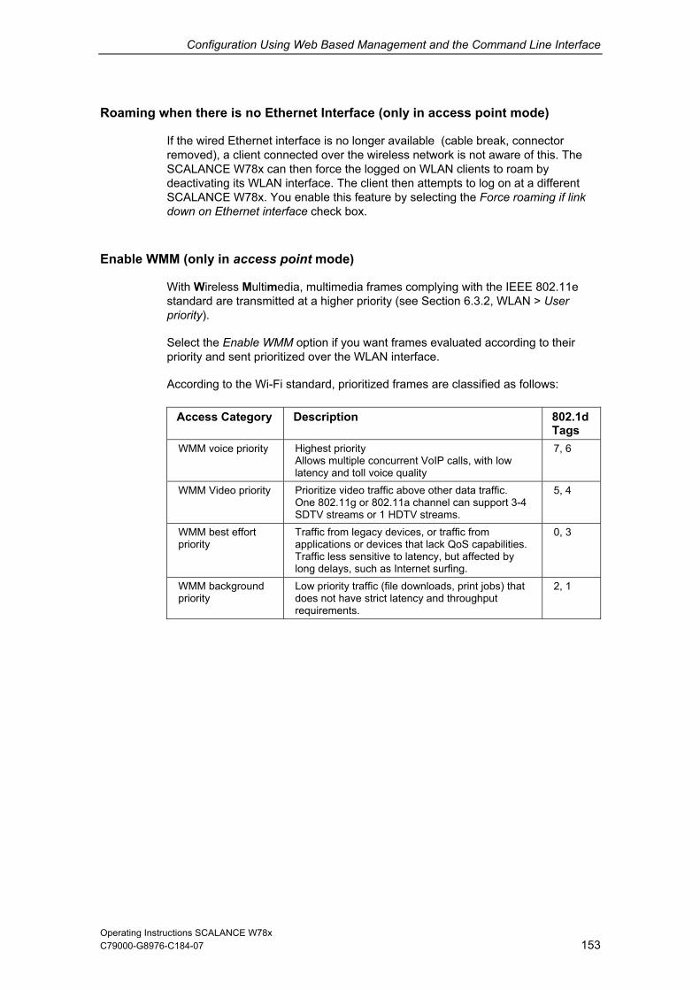
Configuration Using Web Based Management and the Command Line Interface
C79000-G8976-C184-07 153
rface (only in access point mode)
o longer available (cable break, connector r the wireless network is not aware of this. The
E W78x can then force n WLAN clients to deactivating its WLAN s t log on at a different SCALANCE W78x. You he Force roaming if link down on Ethernet inter
E ess p
With Wireless Multimed 02.11e standard are transmitte 6priority).
Select the Enable WMM s evaluatpriority and sent prioriti
According to the Wi-Fi s assified as follows:
Access Category 802.1d Tags
Roaming when there is no Ethernet Inte
If the wired Ethernet interface is nremoved), a client connected oveSCALANC the logged o roam by
interface. The client then attempt enable this feature by selecting t
face check box.
o
nable WMM (only in acc oint mode)
ia, multimedia frames complying wd at a higher priority (see Section
option if you want frame
ith the IEEE 8.3.2, WLAN > User
ed according to their zed over the WLAN interface.
tandard, prioritized frames are cl
Description
WMM voice priority ls, with low
7, 6 Highest priority Allows multiple concurrent VoIP callatency and toll voice quality
WMM Video priority ta traffic. n support 3-4
5, 4 Prioritize video traffic above other daOne 802.11g or 802.11a channel caSDTV streams or 1 HDTV streams.
WMM best effort priority
from S capabilities.
Traffic less sensitive to latency, but affected by long delays, such as Internet surfing.
0, 3 Traffic from legacy devices, or trafficapplications or devices that lack Qo
WMM background priority
Low priority traffic (file downloads, print jobs) that does not have strict latency and throughput requirements.
2, 1
Operating Instructions SCALANCE W78x

Configuration Using Web Based Management and the Command Line Interface
C79000-G8976-C184-07 154
e Syntax of the Command Line Interfac
CLI\INTERFACES\WLAN1\ADVANCED> mmand Description Comment Co
power [0...4
0 Full power
4 Minimum power, -12 dB
] Specifies by how many dB the transmit power will be reduced compared with full power:
1 -3 dB, half 2 -6 dB, quarter 3 -9 dB, eighth
beacon [20 ... 1000] Specifies the beacon interval in milliseconds.
dtim [1 ... 255] Specifies the data beacon rate. Available only in the access point mode.
rtsthr [1 ... 2346] Specifies the packet size as of which RTS/CTS is used.
fragthr [256 ize as of which packets are fragmented.
... 2346] Specifies the s
bkscan [D|I|A] Specifies the mode in which the client scans for further access
Available only in the client mode.
points. D Disabled I Scan if idle A Scan always
bkscanint [200...60000] Interval at which the client scans for further access points.
Available only in the client mode.
bkchannel [channels] Selection of channels on which the for further access
The channels are entered separated anks.
Available only in the client mode. client scans
points.
by bl
bkchsel [E|D] Enables / disables scafurther access points
nning for to specific
nels.
Available only in the client mode.
chan
force [E|D] Enables / disables roaming if the connection is lost on Ethernet
Available only in the access
interface. point mode.
roamthr Decides the threshold at which the client changes to another AP. low changes at a slightly higher field strength to the AP with the stronger signal.medium changes at a moderately higher field strength to the AP with the stronger signal. high changes at a significantly higher field strength to the AP with the stronger signal.
Operating Instructions SCALANCE W78x

Configuration Using Web Based Management and the Command Line Interface
155
Description Comment Command
swretry [E|D] Enables / disables the software retry functionality.
swretno [0 ... 15] Specifies the number of software retries.
hwretno [0 ... 15] Specifies the number of hardware retries.
preamb [E|
802.11b are supported (higher performance).
D] Enables / disables the short preamble.
When this function is enabled, higher data ratesaccording to IEEE
antenna [A|B|SA|SB|D] Specifies which antennas are used: A Only antenna A B Only antenna B SA Antenna A transmits AntenSB Antenna B transmits
With the IWLAN/PB Link with one antenna socket, the default (Antenna A) must not be changed.
na B receives
Antenna A receives D The best of both antennas (diversity)
noise [A|L|M|H] ter A Automatic L Low M Medium
A strong noise filter allows a more stable connection but also a shorter transmission range.
Set the noise fil
H High
wmm [E|D] Enables / disables frame transmission taking into account priority.
antgain [0...30 Set antenna gain in dBi
anttype [0. see the list, enter "anttype ?".
..n] Set antenna type: To
Operating Instructions SCALANCE W78x C79000-G8976-C184-07
Configuration Using Web Based Management and the Command Line Interface
C79000-G8976-C184-07 156
6.3.4 SS mode only)
Not
The SSID List menu is available only when you use the SCALANCE W78x in Clientmode. You can specify the mode in the System menu.
ID List Submenu (client
e
Network Attachment of the Client
Wit a netw
ANY
An numbe cted to 32.
h this men command, you can specify how the SCALANCE W78x connects toork as client:
If the Connect to ANY SSID check box is selected, the SCALANCE W78x in client mode attempts to connect to the network with the best transmission quality and with suitable security settings. If the Suppress SSID broadcastingsetting is made for an access point, the SCALANCE W78x cannot log on there with the SSID.
If this check box is not selected, the SCALANCE W78x attempts to connect to the network from the SSID list that has the best transmission quality.
SSID is absolutely necessary in ad hoc networks and iPCF. The maximum r of SSIDs in the SSID list is restri
Operating Instructions SCALANCE W78x

Configuration Using Web Based Management and the Command Line Interface
C79000-G8976-C184-07 157
Syntax of the Command Line Interface
CLI\INTERFACCom
ES\WLAN1\SSID> mand Description Comment
add <network n ame> Adds a network name (SSID) to the SSID list.
Available only in the clientmode.
edit <index> <networ
Changes the network name (SSID) at the index location in the SSID list.
Available only in the client mode. k name>
delete <Index> client Deletes the network name (SSID) from the SSID list at the index location.
Available only in themode.
6.3.5 Adva
Properties of
The ban ifies data rates up to 11 Mbps, 802.11g
up to 54 Mbps. The 802.11g standard also uses the OFDM
pac
Special Options for 802.11g Settings
Themanmodcom
nced G Submenu
the 802.11g Standard
IEEE 802.11g is upwards compatible with IEEE 802.11b, both use the 2.4 GHzd. In contrast to 802.11b that spec
provides for data rates modulation scheme. This technology divides a data packet into several smaller
kets that are transmitted at the same time at different frequencies.
options you can set in the Advanced G submenu relate to the way in which agement and control data (RTS/CTS frames, beacons) are sent in the 802.11g e. You can also specify that the SCALANCE W78x only supports 802.11g-patible devices.
Operating Instructions SCALANCE W78x

Configuration Using Web Based Management and the Command Line Interface
C79000-G8976-C184-07 158
Handling 802.11b Clients
point automatically detects whether 802.11b clients exist in the . To avoid 802.11g packets colliding with 802.11b packets, the access
2
ox.
her a CTS or RTS/CTS is
802.11g Expan
r, you specify whether or not the short slotnew
With the 802.11g Only Mode parameter, you can specify that only 802.11g clients can log on at the access point and also that only 802.11g rates are permitted (only in the access point mode). In this mode, only the OFDM modulation method is used. This prevents 802.11b devices from registering. If 802.11g Only mode is disabled, both 802.11b devices and 802.11.g devices can register with the access point.
The access environmentpoint can use the RTS/CTS method. With the 802.11g CTS Mode list box, you specify the use of RTS/CTS (only in the access point mode). 0 do not use RTS/CTS. 1 always use RTS/CTS with 802.11g packets.
only use RTS/CTS when there are 802.11b clients in environment.
You can set the data rate for RTS/CTS frames in the 802.11g CTS Rate list b
With the 802.11g CTS Type list box, you specify whetsent.
sions
With the 802.11g Short Slot Time paramete time is used. This short slot time should be supported by all er clients.
Operating Instructions SCALANCE W78x

Configuration Using Web Based Management and the Command Line Interface
C79000-G8976-C184-07 159
Syntax of the Command Line Interface
CLI\INTERFACES\WLAN1\802.11G>
or for the second wireless adapter (if it exists) CLI\INTERFACES\WLAN2\802.11G >
Command Description Comment
ctsmode [0
0 Do not use CTS. 1 Always use CTS.
ending on whether 802.11b
|1|2] Specifies whether the RTS/CTS method is used for 802.11g packets:
Available only in the access point mode.
2 CTS dep
clients exist.
ctsrate [0|1|2|3] rate for 802.11g CTS frames:
3 11 Mbps
Specifies the data
0 1 Mbps 1 2 Mbps 2 5.5 Mbps
ctstype [0|1
y 1 RTS/CTS
] Specifies the method for avoiding 802.11g packet collisions: 0 CTS onl
sslot [E|D] Enables / disables short between data packets.
slot times
only11g [E|D] When this is enabled, only the OFDM modulation technique is supported.
Available only in the access point mode.
overlap [E|Dsearch for on overlapping channels. access point mode.
] If this is enabled, 802.11b are also Available only in the
Optimize [1...4] Specifies the optimization level for detection of 802.11b clients: 1 IEEE standard method
Available only in the access point mode.
2...4 proprietary
Operating Instructions SCALANCE W78x

Configuration Using Web Based Management and the Command Line Interface
C79000-G8976-C184-07 160
and (access point mode only)
Variable S
r sh(8 etcaccess point will t nsmission rates for communication w .
he "Basic Rate“ parameter specifies that a client must be capable of this data rate ble to connect to the access point.
6.3.6 Data Rates Submenu Comm
etting of the Transmission Rates
F om the table02.11b, g, a
owing all available data rates for the current WLAN mode .), you can select any combination of these data rates. The hen use only the selected tra
ith the clients
Tto be a
Figure 6-2 "edit" Screenshot:
Operating Instructions SCALANCE W78x

Configuration Using Web Based Management and the Command Line Interface
C79000-G8976-C184-07 161
Syntax of the Command Line Interface
CLI\INTERF \DCo Descriptio Comme
ACES\WLAN1 ata Rates> mmand n nt
info lowing overview s ows you ilable transmission rates and
nt configuration.
The folthe ava
h
their curre
default s the default setting for the LAN mode
Enablecurrent W
edit <Rate> <E | D> <E | D e settings for the ata rate (in Mbps). The
ameters indicate whether the uld be used or is defined as
Rate". Overview:
abled | Basic Rate
1 | X | X 2 | X | X
| X |
9 | X | 11 | X
Example:
"edit 5.5 d d" sables the data rate 5.5
Mbps. The screenshot shows the default setting for the 802.11g mode.
Changes thspecified dtwo parrate sho"Basic
The command
di
Rate | En
5.5 | X
6 | X
X | X | 12 |
18 | X | 24 | X | 36 | X | 48 | X | 54 | X |
Operating Instructions SCALANCE W78x

Configuration Using Web Based Management and the Command Line Interface
C79000-G8976-C184-07 162
6.3.7 VA mand
D
complete ss poin VAP1...VAP7 if you configured virtual access points at the higher level Interfaces > WLAN (Virtual
AP count > 0).
On this page, you can a e virtual access points; in other words, the access poin
S
Enter the SSID of the V
ure that you als in the e at you assign to
configure sepa ty settings for each virtual access point (see
tion 6.4.1, WBM me N > VAP1...7). The security settings of the VAPs must meet those of the relevant VLANs.
P Submenu Com
escription
You can only the pages of the virtual acce tshave
ssign a separate SSID to tht operates in multiple SSID mode.
SID
LAN here.
Make sclient th
o store the SSID of this VLAN this VLAN.
configuration of th
NoteYou can rate securiSec nu Security > Basic WLAN > WLA 1/2
x of the Command Line Interface Synta
CLI\INTER
or for the second wireless adapter (if it exists) FACES\WLAN1>VAP1>
CLI\INTERFACES\WLAN2>VAP1> Command Description Comment
vap [E|D] Enable /disable virtual access point
ssid [network name] Assigns a network name (SSID).
Operating Instructions SCALANCE W78x

Configuration Using Web Based Management and the Command Line Interface
C79000-G8976-C184-07 163
6.4 The nu
Introduction
In this menu, you configure the security settings with which you want to operate m selecting the authentication and encryption
scheme, this also includes the decision as to whether or not an external Radius s restricted based on MAC addresses (ACL).
Syntax of t
Security Me
your SCALANCE W78x. Apart fro
server is used and whether access i
he Command Line Interface
CLI\SECURITY> Command Description Comment
mgmteth [E|D] It is only possible to configure the SCALANCE W78x over the wired Ethernet interface (E) or over all interfaces (D).
6.4.1 Basic Wireless Menu Command
Authentication
Authentication protects the network from unwanted access.
In the Authentication Type box, you can choose between the following types of authentication:
Open System There is no authentication. Encryption with a fixed key can be selected as an option. You can choose between WEP or AES based on the key length (see Section 6.4.2).
Note With the SCALANCE W78x in iPCF mode, only this setting is possible.
Operating Instructions SCALANCE W78x

Configuration Using Web Based Management and the Command Line Interface
C79000-G8976-C184-07 164
In Shared Key authentication, a fixed key is stored on the client and access cation and encryption. Once again, you can
S based on the key length (see Section 6.4.2).
sing an open system w or shared key in c with e the informat
Shared Key
point. This is then used for authentichoose between WEP or AE
Note When uACL lists, not
ith encryption onjunction ion in Section 6.4.3 ACL menu command..
WPA Secure WPA/RADI ion uses an external RADIUS server (IEEE 802.1x). With this m t a RADI a certificate (EAP-TL er name aPEAP or EAP-TTLS thod M option, the RADIUS elf to the client using a certificate. Following successf t and RADIUS server generate key material that is . AES or TKIP can be used as a secure encryption m
WPA-PSK ntication r (IEEE 802.1x). A fixed key d Key) i
US authenticatethod, the client logs on a
S) or a combination of us / internal authentication me server then identifies its
ul authentication, the clien used for data encryption
ethod.
US server based onnd password (EAP-SCHAPv2). As an
WPA authe(Pre-Share
works without a RADIUS serves stored on every client and access oint and is used for
uthentication and further encryption. AES or TKIP can be used as a secure ethod.
Note The key can be 8 to 63 ASCII characters or exactly 64 aracters
ng. It should be se amp dom numbers, letters (up few repetitioncharacters). Do not rms at could be guessed. If a device is lost or if own, the key should be changed on all devices to maintain security.
paencryption m
hexadecimal chlo lected so that is complex for ex
per-/lowercase), have le consisting of rans and special
use known names, words or tethe key becomes kn
th
802.1x (Radius) Port-related access check over an external RADIUS server (IEEE 802.1x). With this method, the client logs on at a RADIUS server based on a certificate (EAP-TLS) or a combination of user name and password (EAP-PEAP or EAP-TTLS / internal authentication method MSCHAPv2). As an option, the RADIUS server then identifies itself to the client using a certificate. Following successful authentication, the client and RADIUS server generate key material that is used for data encryption. WEP is used as a weak encryption method.
Operating Instructions SCALANCE W78x

Configuration Using Web Based Management and the Command Line Interface
C79000-G8976-C184-07 165
WPA2-PSK is based on the WPA2 standard, WPA authentication, however, RADIUS server. Instead of this, a key (pass phrase) is
WPA2-PSK
operates without a stored on every client
.
the functions of the IEEE 802.11i security standard. WPA2 uses
he normal authentication can be omitted. A RADIUS server is used to authenticate the client with an access point. The
ent logs on at a RADIUS server based on a certificate (EAP-TLS) or a
ethod MSCHAPv2). As an option, the RADIUS server then
WPA-Auto-PSK oint can process both the WPA-PSK as well as
WPA2-PSK type of authentication. This is necessary when the access point ifferent clients, some using WPA-PSK and others WPA2-
ryption method must be set on the clients.
access point can process both the WPA and WPA2 type entication. This is nece e access point co s with t clients, some using W rs WPA2. The sam n
st be se
Encry
Encryption protects the ed data from eavesdropping and corruption. You can only disable encryp selected Open Sys for authentication. All other security methods include both authentication and encryption.
and access point and this is used for authentication and further encryptionAES or TKIP is used as the encryption method, AES represents the standard method.
WPA2 WPA2 (Wi-Fi Protected Access 2) is a further development of WPA and implementsthe additional encryption protocol CCMP that allows fast roaming in mobile adhoc networks with its preauthentication. A client can log on in advance and several access points so that t
clicombination of user name and password (EAP-PEAP or EAP-TTLS / internal authentication midentifies itself to the client using a certificate. Following successful authentication, the client and RADIUS server generate key material that is used for data encryption. AES or TKIP is used as the encryption method, AES represents the standard method.
Setting with which an access p
communicates with dPSK. The same enc
WPA-Auto Setting with which anof authdifferen
ssary when thPA and othe
mmunicatee encryptio
method mu t on the clients.
ption
transferrtion if you have tem
Operating Instructions SCALANCE W78x

Configuration Using Web Based Management and the Command Line Interface
C79000-G8976-C184-07 166
ncryption Methods
WEP (Wired Equivalent Privacy) A weak, symmetrical stream encryption method with only 40- or 104-bit long
orithm (Ron’s Code 4).
ption, TKIP uses changing keys derived from a main key. TKIP can also recognize corrupted packets.
S (Advanced Encryption Standard) thm
E
If you have selected Open System including encryption or Shared Key as the authentication, you will need to define a key in the Keys menu (see Section 6.4.2).
keys based on the RC4 alg
If you have selected WPA-PSK or WPA (RADIUS) as the authentication, the following alternatives are available in the Cipher box:
TKIP (Temporal Key Integrity Protocol) A symmetrical stream encryption method with the RC4 algorithm (Ron’s Code 4). In contrast to the weak WEP encry
AEStrong symmetrical block encryption method based on the Rijndael algorithat further improves the functions of TKIP.
Operating Instructions SCALANCE W78x

Configuration Using Web Based Management and the Command Line Interface
C79000-G8976-C184-07 167
RADIUS A
tion type" selection list to specify a method for external ication. As default, the "Auto" value is selected so that the client provides a
. Any other selection restricts the is step may be necessary because
DIUS servers do not evaluate the response of the client completely or
re available:
.
LS Extensible Authentication Protocol - Tunnel Transport Layer fter setting up the TLS tunnel, MS-CHAPv2 is used for internal
dditional s for WPA-PSK and WPA2-PSK
t up
Suppress
rotect the SCALANCE W78x from unauthorized access.
Note
Since no encryption is used for the SSID transfer, this function can only provide basic protection against unauthorized access. The use of an authentication method (for example WPA (RADIUS) or WPA-PSK if this is not possible) provides higher security. You must also expect that certain end devices may have problems with access to a hidden SSID.
uthentication Method (only for W788 in client mode)
If a client is authenticated over an external RADIUS server, you can use the "RADIUS authenticaauthentRADIUS server with all supported methodssupport by the client to this one method. Thsome RAcorrectly.
The following options a
EAP TLS Extensible Authentication Protocol - Transport Layer SecurityUses certificates for authentication
EAP TTSecurity. Aauthentication.
PEAP Protected Extensible Authentication Protocol. Alternative draft protocol of IETF for EAP-TTLS
A Entrie
To use the WPA-PSK scheme, you must enter a string in the Pass Phrase box thais used by the SCALANCE W78x to initialize dynamic key generation. In the GroKey Update Interval box, you specify the time after which a new key is generated.
SSID broadcasting
With the Suppress SSID broadcasting setting, the SCALANCE W78x is only ever accessible to clients that know its SSID. This method can be used to p
Operating Instructions SCALANCE W78x

Configuration Using Web Based Management and the Command Line Interface
C79000-G8976-C184-07 168
Inter SSID Communication check box
Selecting this check box allows communication between WLAN clients registered
as defined with different SSIDs for
at different SSIDs of an access point.
Example 1: A SCALANCE W788-2xx w
each of the wireless cards. Example 2: A SCALANCE W788-1xx is used with multiple SSIDs.
Note On a SCALANCE W788-2xx, the Inter SSID communication function must enabled on both WLAN interfaces or on all VAPs to allow communication between the clients with different SSIDs.
be
Note
If VLANs are configured for the SSIDs, this setting can prevent communication between the SSIDs according to the VLAN rules.
Intracell Communication list box
Intracell blocking This setting prevents WLAN client communication within an SSID.
Ethernet blocking This setting prevents WLAN client communication over the Ethernet interface of the access point.
Disabled This setting enables both WLAN client communication within an SSID as well as WLAN client communication over the Ethernet interface.
To illustrate the situation, there is an overview of the effects of the Inter SSID Communication and Intracell Communication settings below.
Operating Instructions SCALANCE W78x

Configuration Using Web Based Management and the Command Line Interface
Settings
169
Possible Communication Inter SSID Intracell
mmunication within an SSID
with another SSID
to the Ethernet network communication Co
Enabled Disabled x x x Enabled In
blockitracell
ng x x
Enabled Ethernet blocking
x x
Disabled Di x x sabled Disabled In
blocki x tracell
ng Disabled Ethernet
blocki
ng x
Syntax of the Command Line Interface
CLI\SEC C\WLAN1>
o wireless ada iURITY\BASI
r for the second pter ( f it exists) CLI\SECURITY\BASIC\WLAN2>
Command Description Comment
authent [0|1|2|3|4|5|6|7|8]
tication type. a number e
6 WPA2-PSK 7 WPA-Auto 8 WPA-Auto-PSK
With the authentication types 7 (WPA-Auto) and 8 (WPA-Auto-PSK), the encryption method of WPA and WPA2 or
SK e the same.
Specifies the authenFor the parameter n, enter between 0 and 4 for the typauthentication: 0 Open System 1 Shared Key 2 WPA (RADIUS) 3 WPA-PSK 4 802.1x (RADIUS)5 WPA2
WPA-PSK & WPA2-Pmust b
encrypt [E|D] Encryption enabled / disabled.
cipher [OFF|AUTO|WEP| AES|TKIP]
Specifies the encryption scheme.
keysrc [0..2] Select the key source. Enter 0 as the parameter if the key is managed by the server. Enter 1 in the key will be provided by a RADIUS server. Enter 2 if mixed operation is required.
defkey [1|2|3|4] Selects the default WEP key.
wpaphrase [WPA password] Enter the WPA-PSK password. The password can be 8 to 63 ASCII characters or exactly 64 hexadecimal characters long.
Operating Instructions SCALANCE W78x C79000-G8976-C184-07

Configuration Using Web Based Management and the Command Line Interface
170
Comment Command Description
grkint [interval] Specifies the "Group Key Update Intervals" in WPA-PSK.
Interval in seconds, (0; 36…36000), 0 = OFF
supssid [E| Enable / disable Suppress SSID D] broadcasting functionality.
Intracell cointracom [D|I|E]
Disable = no restriction of data traffic Intracell = blocking of data traffic
clients in the cell king of data traffic to
mmunication Disable / Intracell or Ethernet blocking)
between theEthernet = blocEthernet
Inter SSID ssidcom [E
SSIDs blocked
communication |D]
(Enable / Disable communication to other SSIDs) Enable = data traffic with other SSIDs permitted Enable = data traffic with other
username [name] Specifies the user name for the r.
In client mode only. RADIUS serve
password [password] Specifies the password for the RADIUS server.
In client mode only.
chkserver [E|D] Enables / disables authentication of the server.
In client mode only.
radauth [ty (Set Authen ffered by
TLS,
pe] tication Type oclient to: AUTO, EAP_TLS, EAP_TPEAP)
VAP
h virtual access AP7, you configure the following security scribed earli
For eac point VAP1 to Vsettings de er:
Operating Instructions SCALANCE W78x C79000-G8976-C184-07

Configuration Using Web Based Management and the Command Line Interface
Authentication
Enable encryption
Encryption method
Select the default WEP key
Enter the WPA-PSK password
C79000-G8976-C184-07 171
Specify the Group Key Update Interval in WPA-PSK.
here they apply, all other security parameters are adopted from the Security > > WLAN1 or WLAN2 page.
Enable Suppress SSID broadcasting
WBasic
Operating Instructions SCALANCE W78x

Configuration Using Web Based Management and the Command Line Interface
C79000-G8976-C184-07 172
x terface Synta of the Command Line In
CLI\SECURITY\BASIC\WLAN1>VAP1
ond wireless adapter (if it exists) or for the secCLI\SECURITY\BASIC\WLAN2>VAP1
Command Description Comment
authent [0|1|2|3|
Specifies the authentication type.
1 Shared Key 2 WPA (RADIUS)
WPA-PSK 802.1x (RADIUS)
With the authentication and 8
WPA-PSK & WPA2-PSK must be the same.
4|5|6|7|8] For the parameter n, enter a number between 0 and 4 for the type authentication: 0 Open System
types 7 (WPA-Auto) (WPA-Auto-PSK), the encryption method of WPA and WPA2 or
3 4 5 WPA2 6 WPA2-PSK 7 WPA-Auto 8 WPA-Auto-PSK
encrypt [E|D] Encryption enabled / disabled.
cipher [OFF WEP| AES|TKI
|AUTO|P]
Specifies the encryption scheme.
defkey [1|2|3|4] Selects the default WEP key.
wpaphrase [WPA password] Enter the WPA-PSK password. The password can be 8 to 63 ASCII characters or exactly 64 hexadecimal characters long.
grkint [inter Specifies th Update Intervals" in
Interval in seconds, (0; 36… OFF
val] e "Group Key WPA-PSK. 36000), 0 =
supssid [E|D] Enable / disable Close Wireless System functionality.
Operating Instructions SCALANCE W78x

Configuration Using Web Based Management and the Command Line Interface
6.4.2 Keys Menu Command
C79000-G8976-C184-07 173
pecifying EP/AES Key
ethods, you must first enter at least one key in the key table. You can choose between WEP or AES encryption based on the key length. 5 or 13 ASCII or 10 or 26 hexadecimal characters specify a weak WEP key (40/104 bits).
hand, define a strong AES
g when configuring the keys on the
CALANCE W78x: CL key and the WEP/AES key must be of the same length since the CP 7515
S the W
To allow you to enable the encryption for the Open System and Shared Key authentication m
16 ASCII or 32 hexadecimal characters, on the other key (128 bits).
You can also create keys for WDS Redundancy and ACL Private (these are not supported by all clients for ACL).
Note When operating the CP 7515, note the followinSThe Aonly allows a uniform key length. If the Windows-specific program Zero-Config is used even the keys must be the same.
Syntax of the Command Line Interface
CLI\SECURITY\KEYS\WLAN1>
d wireless adapter (if it exists) or for the seconCLI\SECUR
Description Comment
ITY\KEYS\WLAN2> Command
add <Len> <Key> [index] Adds at a key at the end or at the specified Index of the table.
Indexes from 5 onwards are private keys
edit <index> <Len> <Key> Changes the key at the Index location.
delete <Index> Deletes the key at the Index location.
clearall Deletes all keys.
Operating Instructions SCALANCE W78x

Configuration Using Web Based Management and the Command Line Interface
C79000-G8976-C184-07 174
.4.3 ACL Menu Command
Note
e poin cify the mode in the System menu.
6
Th ACL menu is available only when you use the SCALANCE W78x in the access t mode. You can spe
Access Rig s
The t of MAC addresses and access rights.
neceaddr
is function can only provide basic protection against unauthorized access. The use of an authentication method (for example WPA (RADIUS) or WPA-PSK if this is not possible) provides
ht for Individual Clients
access control list (ACL) is and assignmen
If ACL is enabled, prior to data transfer, the SCALANCE W78x checks whether thessary permissions for the communication partner (identified by the MAC ess) are entered in the ACL table
Note Since no encryption is used for MAC address transfer, th
higher security.
Enabling the ACL
In Web Based Management, there is a list box for the use of ACL. e to either Enabled or
ents entered in th g to the ACL entry. Clients not
entered in the ACL hav This setting can be used to deny access by certain
Strict ts entered in th to the CL entry. Clients not in the ACL hav Th setting can be used to ccess by certain
bled The access control this i
Changing an Entry in the ACL
Click the relevant MAC address to change the entry in the ACL. With the Sel check box, you decide whether or not an ACL entry is used. The Del check box is used to delete an entry from the ACL.
To enable ACL, you must set the global releas Strict:
EnabledAll cli e ACL are handled accordin
e access to the access point.clients.
All clienenteredallow a
e ACL are handled accordinge no access to the access point. clients.
Ais
Disas not used.
Operating Instructions SCALANCE W78x

Configuration Using Web Based Management and the Command Line Interface
New Entry in the ACL
C79000-G8976-C184-07 175
in the ACL. A page appears on which r the MAC address of the client in the
or the ple in the WBM Security menu) that is also used by
for different clients. You must first
pport private keys.
ust be set),if an open system with encryption or shared key is used.
he private key is used on this connection for the transferred unicast packets in ireleAll multicast and broad e access point. The wire must therefore also enter this public key at the s
Click the New button to create a new entry you can make the necessary settings. EnteMAC Address text box. You specify the access permissions of the client in the Permission list box:
Allow The client has access to the access point.
Deny The client does not have access to the access point.
Default Key The client only has access to the access point when it uses the default key for encryption of the data. To allow this, you must specify a valid default key fSCALANCE W78x (for examthe client.
Private Key With this setting, you can use different keyscreate the private keys with the Keys menu command. You can select one of these keys in the Key number list box. The client only has access to the access point when it uses this private key. For this function, the client must su
Note
The private key set in the ACL must also be available in the key list on the client. The client must also use this private key for communication in Security->Basic->WLAN (the key m
Ttended for the w ss client.
cast packets are transferred with the public key set on thless client entered in the ACL listame location in its key list as the access point.
Operating Instructions SCALANCE W78x

Configuration Using Web Based Management and the Command Line Interface
Operating Instructions SCALANCE W78x C79000-G8976-C184-07 176
Example
In its cell, an access point uses the setting shared key with a 128-bit public key (default key 1) for encryption of the data traffic. All wireless clients that register at this access point, require this public key at position 1 in their key list for communication. If access for certain wireless clients is now restricted by the ACL list of the access point on the basis of a private key, the private key must first be stored in the key list of the access point and the client to be restricted. The next activity is to enter the MAC addresses of these wireless clients in the ACL list of the access point and to give it the private key. If these wireless clients are intended to continue communication, the private key must be set on the wireless client directly under Security->Basic->WLAN and used for the encryption. Otherwise the clients could receive broadband or multicast packets, but no longer be addressed directly with unicast packets.

Configuration Using Web Based Management and the Command Line Interface
C79000-G8976-C184-07 177
mand Line Interface Syntax of the Com
CLI\SECUR
or for the second wireless adapter (if it exists) ITY\ACL\WLAN1>
CLI\SECUR AN2Comm Description Comment
ITY\ACL\WLand
>
aclmode [E|D|S] Global releaE Ena
DisaS Stric
se of ACL:
D ble ble t
Only in access point mode
add <MAC> [A|Y|K|P][key] Create a newMAC MAC A Allow Y DenK DefaP Priva Key Key
nt mode
entry in the ACL: Only in access poi address of the client
y ult Key te Key
index for private key
edit <index> [E|D] [A|Y|K|P] [Key]
Change an eindex Num E Enable D Disable A Allow Y Deny K Default Key P Private Key Key Key index for private key
Only in access point xisting ACL entry: ber of the ACL entry mode
delete <Index> Delete an existing ACL entry: index Number of the ACL entry
Only in access point mode
clearall Deletes all ACL entries. Only in access point mode
Operating Instructions SCALANCE W78x

Configuration Using Web Based Management and the Command Line Interface
C79000-G8976-C184-07 178
RADIUS Server Menu Command
menu command is available only when you use the SCALANCE ecify the mode in the System menu.
6.4.4
Note The RADIUS W78x in access point mode. You can sp
Authentication over an External Server
erver. A client can n data of
uthentication
SCALANCE W supports the external authentication mechanisms EAP-TLS, EAP-TTLS and PEAP.
yntax of the Command Line Interface
The concept of RADIUS is based on an external authentication sonly access the network after the SCALANCE W78x has verified the logothe client with the authentication server. Both the client and the aserver must support the EAP protocol (Extensive Authentication Protocol). The
S
CLI\SECURDescription Comment
ITY\RADIUS> Command
server [IP a ] Specifies the IP address of the ddressprimary RADIUS server.
server B [IPbackup RADIUS server.
address] Specifies the IP address of the
port [port] Specifies the port of the primary RADIUS server.
port B [port] Specifies the port of the backup RADIUS server.
Secret [password] Specifies the password for the primary RADIUS server.
secret B [password] Specifies the password for the backup RADIUS server.
maxreq [max. number] Maximum number of queries to the RADIUS server.
maxreq B [max. number] Maximum number of queries to the RADIUS server. (backup server)
authprd [time in s] Period for repeating authentication. The default is 3600 s.
Operating Instructions SCALANCE W78x

Configuration Using Web Based Management and the Command Line Interface
C79000-G8976-C184-07 179
Menu Command
Access Pe
pecify the access permissions for IP addresses. You can specify , Telnet, WBM) is possible with the defined
anagement access is possible with all IP addresses not included in the list.
Note The defined access rights also apply to the PC used for configuration. If you have not entered the local IP address and have set the ACL mode to Accessed, no further access to the SCALANCE W78x is possible. You should also note that the IP address of the client can change if you use DHCP without reservation.
6.4.5 Access
rmissions for IP Addresses
In this menu, you swhether management access (SNMPaddresses:
Management access is possible only with the defined addresses.
Or:
M
Syntax of the Command Line Interface
CLI\SECURITY\ACCESS> Command Description Comment
access [E|D] Enable / disable access control list.
statmgmt [A|D] It is possible to access or not possible to access the IP addresses of the access control list (Accessed / Denied).
add <IP> Adds a new IP address
edit <Index|IP> [E|D] Enables / disables the entry in the table specified by the index or IP address.
delete <Index|IP> Deletes the entry.
clearall Clears the access control list.
Operating Instructions SCALANCE W78x

Configuration Using Web Based Management and the Command Line Interface
C79000-G8976-C184-07 180
Introduction
tworks. A bridge is not dependent on the protocol; management of the data packages is based on the
exchange between wired and wireless Ethernet. The following sections describe e functions that are available and how you configure and use them.
Deleting A
The SCALANCE W78x saves the information about which MAC address can be in a learning table. Entries in this list are deleted
to s no further data transfer for the corresponding MAC addresse e the length of time after which addresses are deleted if
ging Time parameter on the start page of the Bridge en
Syntax of the Command Line Interface
6.5 The Bridge Menu
A bridge is a network component that connects two ne
physical address of the network nodes (MAC address).
The SCALANCE W78x provides bridge functionality because it handles data
th
ged Bridge Information
reached over which portau matically when there i
s. You can decidno data is sent using the Am u.
CLI\BRIDG >Description Comment
E\ Command
aging [E|D|ag bles automatic the
s and rts. With the Aging time
ge the time.
Values between 10 s and 1,000,000 s are possible for the Aging time. The default is 300 s (5 min)
ing time] Enables / disadeletion of information onassignment of MAC addressepoparameter, you can chan
Operating Instructions SCALANCE W78x
Configuration Using Web Based Management and the Command Line Interface
C79000-G8976-C184-07 181
6.5.1 WDS Menu Command
Note The WDS menu command is available only when the SCALANCE W78x is used in access point mode and iPCF is not activated. You can specify the mode in the System menu.
Communication between SCALANCE W78x Devices
and communicates with clients. There are, however, situations in which several
other, for example to extend wireless coverage or to set up a wireless backbone. This mode is possible
h S (Wireless Distributed System).
t
Wit be recosysName.
hese functions are then based on the MAC address that changed with the tion of VAPs with V3.0.
In normal operation, the SCALANCE W78x is used as an interface to a network
SCALANCE W78x devices need to communicate with each
wit WD
No e h the firmware update to ≥ V3.0, the SCALANCE W78x-xRR devices need tonfigured if you use WDS or redundancy and use the MAC address and not the
Tintroduc
Configuration
In the MAC / sysName column, enter the MAC address or the system name of the SCALANCE W78x with which you want to communicate. If you select the Enc check box, encryption is used.
Operating Instructions SCALANCE W78x

Configuration Using Web Based Management and the Command Line Interface
C79000-G8976-C184-07 182
wing restrictions apply:
ANCE W78x devices that will comm each other must use the same channel.
nc EP and AES.
If you want to attach a di ALANCE W78x over WDS, you must configure sName parameter does not work
In the IEEE 802.11h tran e, it is not practical to select the WDS mode at the same time. I use the same channel. If er is detected by an AP,
e channel is changed a n
Note
In WDS mode, the follo
All SCAL unicate with
You can only use the e ryption schemes W
fferent access point from the SC the MAC address. Detection using the sy
in this situation.
smission modn WDS mode, all SCALANCE W78x devices must a signal from a primary us
thterminated.
utomatically and the existing connection is the
To enable the entry, you mus check box.
Syntax of the Command Line Interfa
t select the Sel
ce
CLI\BRIDGE\WDS\WLAN1>
or for the second wireless adapter (if it exists) CLI\BRIDGE\WDS\WLAN2>
nt Command Description Comme
a
Adds aeither asysNamparamdisable on. If encryption is enablespecifi
dd <MAC|Name> [SE|SD][Key]
new WDS connection. Enter MAC address or a e. With the SE or SD
eters, you can enable or encryptid, the key must also be ed.
edit <index> [E|D] [SE|SD] [Key]
Changes the WDS connection specified by Index. With [E|D], you can enable / disable the connection.
delete <Index> Deletes the connection with the specified index.
clearall Deletes all WDS connections.
Operating Instructions SCALANCE W78x

Configuration Using Web Based Management and the Command Line Interface
6.5.2 VLAN Menu Command
C79000-G8976-C184-07 183
Assignment and Management of the VLAN IDs
The Current VLAN Configuration dialog displays a table with an overview of the
t displays LAN. The
sequence is sorted from left to right in ascending order; in other words, according to the ID of the interface (WLAN 1, WLAN 1 VAP 1, WLAN 2 VAP 2… or WLAN 1 WDS 1, WLAN 1 WDS 2...).
Entries in red, indicate members in the table, entries in black indicate the configured port VLAN IDs.
at is not the same as the port VID,
u
Note
e VLAN tags from outgoing frames. es always remove all VLAN tags from the
outgoing frames.
configured VLAN IDs (VID).The assignment of the configured ports of the access point is also displayed as a member of these VLANs.
The Name is used to identify an entry within the current table. Member Lis'U' for untagged member of a VLANs or '–' if a port is not member of a V
If an interface is member of a VLAN ID, thframes arriving from Ethernet with this VLAN ID are accepted. Outgoing frames, however, always have the port VLAN ID.
Click on VID or Name to open the configuration page for VLAN IDs. With New, yocreate a new VLAN ID, with Refresh, you can update the table.
The Ethernet interface does not removIf the VLAN is active, the WLAN interfac
Member List Meaning U If VID equals port VID; in other words untagged frames
from WLAN are given this VID. U If the port is a member of the VID; in other words, tagged
rnet are forwarded on this port. frames from Ethe— If the port is not a member of the VID; in other words, all
the frames coming from Ethernet are blocked / discarded with the corresponding VLAN ID. Frames containing unconfigured VIDs and untagged frames are always blocked if the VLAN is active.
Operating Instructions SCALANCE W78x

Configuration Using Web Based Management and the Command Line Interface
Operating Instructions SCALANCE W78x 184 C79000-G8976-C184-07

Configuration Using Web Based Management and the Command Line Interface
C79000-G8976-C184-07 185
an no longer be modified.
Representat Settings Meaning
VLAN ID Settings
The VLAN ID box allows you to enter a new VID as long as no port is assigned explicitly as member. Otherwise, the VID c
ion 1
deleted when you exit this page. Clicking on the field changes to depiction 2.
Field can be edited. If all editable boxes are displayed in this way and if the VID is not configured as port VID, the VID is
2
dited. Clicking on the field changes to depiction 1. Field can be e
3 Al entries for VLAN membership are being used.
Field cannot be edited.
4 corresponds to the port VID
Field cannot be edited. VID
5 Corresponding port is set to all VIDs,
Field cannot be edited.
Operating Instructions SCALANCE W78x

Configuration Using Web Based Management and the Command Line Interface
C79000-G8976-C184-07 186
the ports in the form of a table.
ID for WLAN interface WDS or manageme
Priority: Configured port.
: VLAN ID d igned to the port.
ber: The VLAN
: VLAN suppo
Clicking on a port op ettings configuration page.
Ports
Port: Overview of
SSID: SSredundancy.
, no entry for nt and
priority of the
Port VID irectly ass
Mem membership assigned to the port.
Enabled rt can then be enabled / disabled dire
ens the VLAN S
ctly.
Note
If you use a Radius server for authentication, this must the accessible over the management VLAN. Among other things, the management port also handles the functions: HTTP, HTTPS, WBM, Telnet, SSH, Ping, DHCP, TFTP, SNMP, SNTP and Syslog.
Note The IP and MAC-based nodes downstream from a client with enabled layer 2 tunneling function ( L2T client) adopt the same VLAN properties as the client.
Operating Instructions SCALANCE W78x

Configuration Using Web Based Management and the Command Line Interface
C79000-G8976-C184-07 187
nt is connected to the access point over the WLAN1 VAP3 interface. WLAN1 VAP3 is a member of the VLAN ID 33 that is assigned priority 6.
ices connected downstream from the L2T client and the client itself are also members VLAN ID 33 with priority 6.
Example: An L2T clie
For the L2T port, this means that the dev
Operating Instructions SCALANCE W78x

Configuration Using Web Based Management and the Command Line Interface
C79000-G8976-C184-07 188
VLAN Setti
VLAN
User Pgiven
Port VLAN ID: Entry of the VLAN ID.
VLANAll VID ing of the port as member of all configured VIDs.
Specif VIDs per port.
ngs
enabled: VLAN support can then be enabled / disabled directly.
riority: Prioritization of the data traffic over the port. Untagged frames are this priority.
Membership s: Automatic sett
ic VIDs only: Member of up to eight, freely assignable configured
Operating Instructions SCALANCE W78x

Configuration Using Web Based Management and the Command Line Interface
C79000-G8976-C184-07 189
LAN enable (only in access point mode of a W788xRR)
User priori
Specify the priority of the frames of this VAP with the User priority list box. The priority is evaluated by the connected VLAN-compliant switches (for example,
he ascending numbers. The exception is
e
V
Select the VLAN enable option if you want to enable the VLAN function. If VLAN enable is selected, all frames of this VAP are given a VLAN tag.
ty (only in access point mode of a W788xRR)
SCALANCE X400) of the network. The priority rises with the ascending numbers:
Note The priority generally increases with tpriority 0, that has a higher priority than priority classes 1 and 2 and has the sampriority as class 3.
0 - Best Effort (BE)
1 tical data traffic
2 - Spare
3 lent Effort (EE)
4 - Cont
5 - Voice (VI), < 100 ms latency and jitter video/multimedia
6 - Voice (VO), < 10 ms latency and jitter voice over IP PNIO
7 - Network Control (NC) internal network control frames
Default is 0 - Best Effort (BE).
Note
Both voice over IP and PNIO have priority 6.
normal data traffic
- Background (BK) non time-cri
(--) this priority is reserved
- Excel data traffic with highest priority
rolled Load (CL)
Operating Instructions SCALANCE W78x

Configuration Using Web Based Management and the Command Line Interface
C79000-G8976-C184-07 190
Port VLAN ID (o
Here, will co
ual VLANs are configured in the VLAN-compliant switches (for example SCAL
W788xRR)
port VLAN ID (VID) entered above will be assigned to.
The following alternatives in the assignment are possible:
Th
onmber only of the VLANs entered below. VLAN ID (VID) of up to 8 VLANs in which the VAP will be a
m
nly in access point mode of a W788xRR)
you enter the VLAN ID (VID) of the VLAN on which the virtual access point mmunicate.
The individANCE X400). The VID of a VLAN is in the range from 1 to 4094.
VLAN membership (only in access point mode of a
Here, you specify the VLANs for which the virtual access point will be a member or which other VLANs the
all e VAP is member of all VLANs.
ly The VAP is meHere, enter the
ember.
Operating Instructions SCALANCE W78x

Configuration Using Web Based Management and the Command Line Interface
C79000-G8976-C184-07 191
yntax of the Command Line Interface S
CLI\BRIDG
scription
EVLAN\VLAN_ID>
Command De
info Shows the currently configured VLANs and their relationship to the ports.
add <VLAN-ID> [u [Ports]] InsePorts:
rts a new VLAN. Specifies the ports
configured for the VLAN. u: The port is a member of the VLAN. sent without VLAN
th the VLAN ID 100. Ports 2 and 4
Frames are tag. Examples: add 100 u 2 4 Creates an entry wiare members of this VLAN.
edit <VLAN-ID> [- [Ports],] [u [Ports],]
of ports in a VLAN. The parameters correspond to those of the add command. Examples: edit 100 - 2
the V
Changes the membership
Port 2 no loner belongs to LAN with ID 100.
delete <VLAN-ID> Deletes the VLAN with the specified VLAN ID from the Econfiguration of the SCALANC W78x.
C ORTS>
Command Description
LI\BRIDGE\VLAN\P
info Displays an overview of the poVLAN settings.
r and corresponding ts
vlan <Port> <E|D> e specified port. Enables / disables VLAN for th
portvid <Port> <VLAN-ID> LAN tag at the specified LAN tag with the <VLAN-ID>.
Received frames without a Vport are given a V
portprio <Port> <Priority> ccording to The priority assigned to untagge802.1d.
d frames a
member <Port> <all|specific> er of all VLANs or only the ID (specific, see above).
The specified port is a membVLAN configured in VLAN
Operating Instructions SCALANCE W78x
Configuration Using Web Based Management and the Command Line Interface
6.5.3 Learning Table Menu Command
C79000-G8976-C184-07 192
ssignmen AC Address A t of M and Port
wireless interfaces. The
SCALANCE W78x obtains this information from the active data exchange. The learning table also contains information on clients and on up to 8 devices
the layer 2 tunneling mode.
6.5.4 AR
dress
Address Resolution Protocol) obtains the corresponding MAC ress. The page of this menu command also indicates
e over which an addres ched. The last colu es the information wa amic if it was obtained during
r static if it w
6 ree Menu
The Spanning Tree me se the W78x in th peu.
The learning table contains the information about whether a MAC address can bereached over the wired Ethernet interface or over the
connected downstream from it operating in
P Table Menu Command
Assignment of MAC Address and IP Ad
The ARP protocol (address of a known IP addthe interfac s can be rea mn indicathow operation o
s obtained (for example dynas configured).
.5.5 Spanning T Command
Note nu command is available only when you u
SCALANCESystem men
e access point mode. You can s cify the mode in the
A edundant
ing tree algo b created in which there l connection tree prevents loops being
formed in the network by all eactivating the other edundant) ports for data traffic. If there is an interruption, the data can be sent ver an alternative path. The functionality of the spanning tree algorithm is based
on the exchange of configuration and topology change frames.
voiding Loops on R Connections
The spann rithm allows network structures tos between two stations. Spanning
owing only one path and d
eare severa
(ro
Operating Instructions SCALANCE W78x

Configuration Using Web Based Management and the Command Line Interface
C79000-G8976-C184-07 193
gy Using the Configuration Frames
rk components exchange configuration frames known as BPDUs (Bridge e is
e root bridge is g tree algorithm for all involved components.
atus change of the bridge ports.
Rapid Spanning Tree
The rapid spanning tree algorithm is based on the spanning tree algorithm. This es for
Edge ports
configuration frames). When the hello time has elapsed, the station can be certain that no further configuration frame will arrive and that this port is an edge port. If the user wants to avoid the hello time, spanning tree can
disabled at this port.
ate Port (substitute for the root port) is
ee, ports affected by a reconfiguration are immediately deleted from the filter table. With spanning tree, on the other hand, the point at which a port is deleted is decided by the time when the port was entered in the filter table.
Reaction to events Rapid spanning tree reacts to events, for example an aborted connection, without delay. There is no waiting for timers as in spanning tree.
In principle, therefore with rapid spanning tree, alternatives for many parameters are preconfigured and certain properties of the network structure taken into account to reduce the reconfiguration time.
Definition of the Network Topolo
NetwoProtocol Data Unit) with each other to calculate the topology. The root bridgselected and the network topology created using these frames. Ththe bridge that controls the spanninBPDUs also bring about the st
was optimized in terms of the reconfiguration time. Typical reconfiguration timspanning tree are between 20 and 30 seconds. With rapid spanning tree, the reconfiguration times are around 1 second. This was achieved by the following measures:
A port defined as an edge port is activated after the hello time (the time between two
be
Point to Point (direct communication between two neighboring stations)By directly linking network components, a status change (reconfiguration of theports) can be made without any delays. A point-to-point connection can, for example, be a WDS connection between two access points.
AlternA substitute for the root port is configured. If the connection to the root bridgelost, the station can establish a connection over the alternate port without any delay by reconfiguring.
Filter table In rapid spanning tr
Operating Instructions SCALANCE W78x
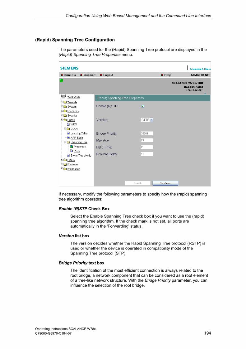
Configuration Using Web Based Management and the Command Line Interface
C79000-G8976-C184-07 194
apid) Spanning Tree Configuration
The parameters used for the (Rapid) Spanning Tree protocol are displayed in the (Rapid) Spanning Tree Properties menu.
(R
If necessary, modify the following parameters to specify how the (rapid) spanning tree algorithm operates:
Enable (R)STP Check Box
Select the Enable Spanning Tree check box if you want to use the (rapid) spanning tree algorithm. If the check mark is not set, all ports are automatically in the 'Forwarding' status.
Version list box
The version decides whether the Rapid Spanning Tree protocol (RSTP) is used or whether the device is operated in compatibility mode of the Spanning Tree protocol (STP).
Bridge Priority text box
The identification of the most efficient connection is always related to the root bridge, a network component that can be considered as a root element of a tree-like network structure. With the Bridge Priority parameter, you can influence the selection of the root bridge.
Operating Instructions SCALANCE W78x

Configuration Using Web Based Management and the Command Line Interface
C79000-G8976-C184-07 195
ity (in other words, with the lowest value for this parameter) becomes the root bridge. If several network components in a
e the Bridge Identifier. Since the root
bridge manages all path changes, it should be located as centrally as
ultiple of 4096 with a range of values from 0 through 61440.
Max Age text box
ure the network.
Hello Time
PDUs). The interval between two such frames is the Hello Time. The default for this parameter is 2 seconds.
d Delay text box
fter the ied in the Forward Delay parameter. This ensures that operation d with the new topology after all the bridges have the required
ds.
Syntax of the Command Line Interface
The bridge with the highest prior
network have the same priority, the station whose MAC address has the lowest numeric value will become the root bridge. Both parameters, bridgpriority and MAC address together form
possible due to the propagation time of the frames. The value for the bridge priority is a whole m
Max Age is the time that a bridge waits for a configuration frame (BPDU). When this time has elapsed, the bridge attempts to reconfigThe default for this parameter is 20 seconds.
text box
Each bridge regularly sends configuration frames (B
Forwar
New configuration data is not used immediately by a bridge but only aperiod specifis only starteinformation. The default for this parameter is 11 secon
CLI\BRIDGE\SPANNING> Command Description Comment
info Displays the current Spanning Tree configuration.
spanning [E|D] algorithm. Enables (E) or disables (D) the (R)STP
version [R | S] Specifies whether the Rapid Spanning Tree (R) or Spanning Tree (S) mode is used.
bridge [0 ... This specifies the bridge priority for the Default value: 32768 61440] SCALANCE W:
hellotm [1 ... 10] alue: 2 s Specifies the interval between two BPDUs in seconds.
Default v
fwd_delay [ . Specifies the delay time for the Default value: 11 s 4 .. 30] effectiveness of configuration information (specified in seconds).
maxage [6 ... 40] Maximum age for configuration information. (specified in seconds)
Default value: 20 s
Operating Instructions SCALANCE W78x

Configuration Using Web Based Management and the Command Line Interface
C79000-G8976-C184-07 196
Spanning T e
Port-Specific Parameters
This ither using the automatic function of the SCALANCE W or by the user.
re Port Settings
page displays the current port parameters. The settings are made e
The eight columns of the port table show the following information:
Port
Specifies the ports to which the information relates. Wireless 1_2, for example, relates to the virtual access point VAP2 on the first WLAN interface.
Priority
With this parameter, you specify the priority of the ports of a bridge.
If the path calculated by spanning tree is possible over several ports of a station, the port with the highest priority (in other words the lowest value for this parameter) is selected. A value from 0 through 255 can be specified for the priority; the default is 128.
Operating Instructions SCALANCE W78x

Configuration Using Web Based Management and the Command Line Interface
C79000-G8976-C184-07 197
These parameters are used to calculate the path that will be selected. The wer the value, the greater the probability that the corresponding path will
rts of a bridg the same value, the port with the st port number will be s ending on whether TP
was selected a of STP Cost or STP Cost will be used.
The calculation st is based mainly on the transmission rate. higher the he lowe the value for Path
Cost should be
Typical path co apid Spanning Tree:
Data Rate Path costs STP Path costs RSTP
STP Cost & RSTP Cost
lobe used. If several polowe
e haveelected. Dep STP or RS
s the version, the value R
of the path coThe achievable transmission rate, t
. r
sts for Spanning Tree and R
100 Mbps 19 200.000
54 Mbps 33 370.370
48 Mbps 6.66736 41
36 Mbps 43 555.556
24 Mbps 53 833.333
18 Mbps 58 1.111.111
12 Mbps 83 1.666.667
11 Mbps 90 1.818.182
10 Mbps 2.000.00 100 0
9 Mbps 2.222.222 111
6 Mbps 3.333.333 166
5.5 Mbps 181 3.636.36 4
2 Mbps 10.000.000 500
1 Mbps 20.000.000 1000
The values can ent individually.
The following entries are possible in this column:
yes An edge port is connected to this port.
pann e or ra tree device is c to this
If n edg is connected, a SCALANCE W can switch over the port t taking into accou t spanning tree fra nning tre
ceived despite this setting, the port automatically changes to the no setting for further stations.
, however, also be s
Edge
no A s ing tre pid spanning onnected port.
a e portu
more e quickly witho
frame is ren mes. If a spa
Operating Instructions SCALANCE W78x

Configuration Using Web Based Management and the Command Line Interface
C79000-G8976-C184-07 198
Note ts with the layer 2 tunneling function enabled connect to the access point, a
not, however, be iority and path
lient is connected to the access point are
If clienseparate port is opened for each of these clients. These ports canconfigured for Rapid Spanning Tree. The settings (for example, prco ts etc.) of the cell over which the csadopted.
Example: An L2T client is connected to the access point over the WLAN1 VAP3 AN1 VAP3 are: priority 128, path 0 and the setting EdgePort enabled
t adopted because layer 2 tunneling clients
onnected together over this port. There are three possible statuses :
ForceFalse
d.
(Wireless 1_3) interface. The settings for WLcosts for STP of 100, path costs for RSTP of(in other words, there is an end device on this port). These settings are adopted for the L2T port with one exception.
The Edge-Port enabled setting is noand the ports downstream from the client can never be edge ports.
P.t.P.
There is a point-to-point link when two RSTP-compliant network componentsare c
ForceTrue Even with half duplex, a direct link is assumed.
Despite a full duplex connection, a point-to-point link is not assumed.
Auto Point-to-point is detected automatically. If the port is set to half duplex (shared media connection), a direct link is not assume
Operating Instructions SCALANCE W78x
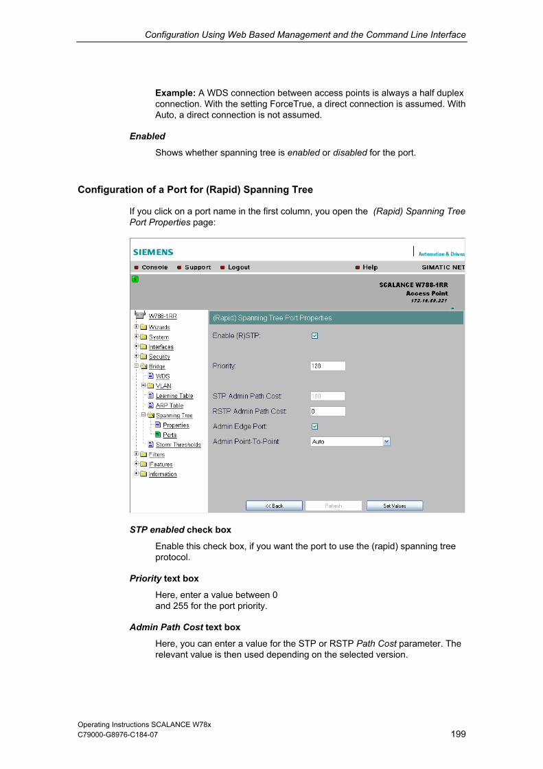
Configuration Using Web Based Management and the Command Line Interface
C79000-G8976-C184-07 199
on between access points is always a half duplex
Configurat id) Spanning Tree
If you click on a port name in the first column, you open the (Rapid) Spanning Tree Port Properties page:
Example: A WDS connecticonnection. With the setting ForceTrue, a direct connection is assumed. With Auto, a direct connection is not assumed.
Enabled
Shows whether spanning tree is enabled or disabled for the port.
ion of a Port for (Rap
STP enabled check box
Enable this check box, if you want the port to use the (rapid) spanning tree protocol.
Priority text box
Here, enter a value between 0 and 255 for the port priority.
Admin Path Cost text box
Here, you can enter a value for the STP or RSTP Path Cost parameter. The relevant value is then used depending on the selected version.
Operating Instructions SCALANCE W78x

Configuration Using Web Based Management and the Command Line Interface
C79000-G8976-C184-07 200
o for the RSTP value, the value for the path costs is atically.
check box
ise a
Here, there are three possible settings:
n is selected: ry ForceFalse in the port table.
corresponds to the entry Auto in the port table.
Point-to-point means a direct connection between two stations. A shared media connection would, for example, be a connection from the Ethernet port to a hub or
ccess points.
If you enter a zercalculated autom
Admin Edge Port
Enable this check box if an end device is connected to this port, otherwreconfiguration of the network will be triggered by every link change.
Admin Point to Point Status check boxes
Shared media ConnectioThis corresponds to the ent
Point to Point Connection is selected: This corresponds to the entry ForceTrue in the port table.
Point to Point Connection and Shared Media Connection are notselected: This
Note
a WDS connection between two a
Syntax of the Command Line Interface
C PANNING\PORTCommand Comment
LI\BRIDGE\S S> Description
info Displays the current Spanning Tree configuration for all ports.
portstp <E|D> [ports] sables the spanning tree Enables / dialgorithm for the specified ports.
portprio <Port> [0 ... 255]
Specifies the priority of the port. Default value: 128
stp_cost [1
<Port> ... 65535]
Specifies the path costs for the port if Version is set to STP.
Default value: 100
Operating Instructions SCALANCE W78x

Configuration Using Web Based Management and the Command Line Interface
Command Des
201
cription Comment
rstp_cost <Port> [0 ... 200000000]
Specifies the path costs for the port if Version is set to RSTP. If the value
Default value: 0
is 0, the value is calculated.
edgeport <Port> [T|F] Specifies whether or not an edge port (T) or a station (F) that supports spanning tree or rapid spanning tree is attached to this port. if a (rapid) spanning tree protocol is received, the value F is displayed automatically.
ptpport <podirect link between two stations. In this case, you have the following
ort recognizes a PtP port based on the duplexity. In full duplex, a PtP link is assumed, in half duplex no PtP link is assum dium).
T
F en
rt> <A|T|F> The point-to-point link establishes a
options: A The p
ed (shared me Specifies a PtP link, even
though half duplex is being used.
Specifies that there is no PtPlink over the relevant port evwith full duplex.
Operating Instructions SCALANCE W78x C79000-G8976-C184-07

Configuration Using Web Based Management and the Command Line Interface
C79000-G8976-C184-07 202
d
6.5.6 Storm Threshold Menu Comman
Note Storm Threshold is available in access point and in the client mode. The functioncan only be used in client mode if NAT is disabled.
Limitation of Broadcast and Multicast Frames
it is exceeded, the SCALANCE W78x stops processing such frames for 30 seconds.
Syntax of the Command Line Interface
Storm Threshold is the maximum number of broadcast or multicast frames per second forwarded by the SCALANCE W78x. If this lim
CLI\BRIDG THR> Command Comment
E\STORMDescription
stormthr <E|D> bles the storm Enables / disathreshold function.
broadcast <limit value> ber of Specifies the maximum numbroadcast packets per second from the same address.
multicast <limit value> Specifies the maximum number multicast packets per second from the same address.
broad_eth <limit value> maximum number of Specifies thebroadcast packets per second for the Ethernet interface.
multi_eth <limit value> Specifies the maximum number of cond for the
multicast packets per seEthernet interface.
broad_1 <limit value> broad_2 <limit value>
broadcast packets per second for the first or second wireless interface.
Specifies the maximum number of
multi_1 <limit value> multi_2 <limit value>
Specifies the maximum number of multicast packets per second for the first or second wireless interface.
Operating Instructions SCALANCE W78x

Configuration Using Web Based Management and the Command Line Interface
C79000-G8976-C184-07 203
ote enu command is available only with the following variants:
)
6.5.7 NAT Menu Command
NThis m• SCALANCE W746-1PRO • SCALANCE W747-1RR • SCALANCE W78x (client mode only
What is NAT?
nslation (NAT), the IP address in a data packet is placed by another. NAT is normally used on a gateway between a private LAN
al network with globally valid IP addresses. A local IP address of the l LAN is changed to an external global IP address by a NAT device at the
To translate the internal into the global IP address, the NAT device maintains a
What is NA
is n list of the NAT gateway and translated for the external
s.
its own external source IP address in the header of these forwarded frames. Since the forwarded frames have the same lobal source IP address, the NAT gateway assigns the frames to the clients using
nt port number.
With Network Address Trareand an externinternagateway.
translation list.
PT?
In Network Address Port Translation (NAPT) or Port Address Translation (PAT), several internal source IP addresses are translated into the same external source IP address. To identify the individual source nodes, the port of the source device also stored in the translatioaddres
If several local clients send a query to the same external destination IP address over the NAT gateway, the gateway enters
gdiffere
Operating Instructions SCALANCE W78x

Configuration Using Web Based Management and the Command Line Interface
Note
NAT/NAPT is possible only on layer 3 of the ISO/OSI reference model. To use the NAT function, the networks must use the IP protocol. When using the ISO protocol that operates at layer 2, it is not possible to use NAT.
Operating Instructions SCALANCE W78x 204 C79000-G8976-C184-07

Configuration Using Web Based Management and the Command Line Interface
C79000-G8976-C184-07 205
Devices
When using the WLAN clients SCALANCE W746-1PRO, W747-1RR and W78x (in ode) as NAT gateways, the WLAN clients must be connected over the
The local IP address of the WLAN client on the Ethernet devices must be entered s the gateway address.
ress assignment differs depending on the communication direction:
ss point: Dynamic address assignment (NAT) The continuous address assignment is made automatically.
rnet device: Static address assignment (NAPT) s a parameter.
Configurat
on the IP Network Address Translation page with the
NAT Properties of the SCALANCE
client mEthernet port with the local Ethernet devices.
a
The add
From Ethernet device to acce
From access point to EtheThe address assignment is fixed and must be set a
32 entries can be set as NAT gateways per WLAN client.
ion
Set the configurationfollowing settings:
Enable NAT Click the check box Enable if you want to enable NAT. Caution: The change is adopted only after a restart!
N client.
local Ethernet network here, if applicable.
Del his
Sel Select the Select check box if you want to enable the current entries.
CP and UDP frames must have their parameters set separately.
Global Port Enter the number of the global port (for TCP or UDP).
Note If the port is already occupied by a local service (for example Telnet), a warning is displayed. In this case, avoid using port 23 (Telnet) and port 80 (http: availability of the client with the WBM) as global port.
Local IP Here, you enter the local IP address for the Ethernet port of the WLA
Subnet Mask Enter a subnet mask for the
Select the Delete check box if you want to delete the previous entries on tpage.
Type Here, you select the assignment TCP or UDP for the following global port. T
Operating Instructions SCALANCE W78x

Configuration Using Web Based Management and the Command Line Interface
C79000-G8976-C184-07 206
l Address
T
• PST over the Ethernet interface: s changed.
LocaHere, you enter the local address of the Ethernet device.
Local Port Here, you enter the number of the local port of the Ethernet device.
Note The following instructions apply only to the IP parameter assignment using the PStool. When the module is accessed with PST by a configuration computer, the address assignment differs depending on the interface: • PST over the wireless interface:
The global address is changed.
The local address i
Operating Instructions SCALANCE W78x

Configuration Using Web Based Management and the Command Line Interface
C79000-G8976-C184-07 207
ommand Line Interface Syntax of the C
CLI\BRIDGC
E>nat ommand Description Comment
nat [E|D] Enables/disables NAT
ip [IP addre Sets the local IP address for the Ethernet port
ss]
subnet [Subnet mask] Sets the subnet mask for the Ethernet port
static Opens the "STATIC" menu
CLI\BRIDGComma Comment
E\NAT>subnet nd Description
Local Subnet 255.2
mask : value of the local subnet mask55.255.0
CLI\BRIDGCommand Description Comment
E\NAT>STATIC
add <type>L IP> < type = TCP or UDP
G port = global port
<G port> L port>
Add the static NAT entry: <
L IP = local IP L port = local port
edit <Index> <E|D> [type] [G port] [L IP] [L port]
Edit the static NAT entry: index = index in table type = TCP or UDP G port = global port L IP = local IP L port = local port
delete <Index> Deletes a static NAT entry
clearall Deletes all static NAT entries
CLI\BRIDGE\NAT\STATIC>info
Index Enabled Type Global Port Local IP Local Port1 x TCP 21 172.27.138.2 1026
Example of static information
Operating Instructions SCALANCE W78x

Configuration Using Web Based Management and the Command Line Interface
C79000-G8976-C184-07 208
6.5.8 IP Mapping Table Menu Command
vailable only with the following variants:
RO R
Note This menu command is a• SCALANCE W78x in client mode • SCALANCE W746-1P• SCALANCE W747-1R
WLAN Access by Several Devi
With the devices listed in the first paragraph, you can prov e WLAN several devices with do very
device with its own wire
This so-called IP mapp ly if the connected devices are addressed only by IP frames. Communication at MAC address level (ISO/OSI layer 2) can
be established with one component whose MAC address is configured on the client,
be established with a maximum of eight components if the layer 2 tunneling function is selected.
The layer 2 tunneling setting meets the requirements of industrial applications in which MAC address-based communication takes place with several devices downstream from the client. Clients with this setting cannot connect to standard Wi-Fi devices and access points with firmware V3.0 or older. For further information, refer to Section 5.4.6.
MAC Mode
IP frames in the direction from the client to the access point always have the MAC address of the WLAN interface as the source MAC address. As a result, the ARP tables at the access point end always contain only the MAC address of the WLAN interface of the clients.
If there are further devices downstream from the client, the Auto Find 'Adopt MAC' option should not be enabled. In this case, the MAC address would be assigned indiscriminately to the first device that signals over Ethernet.
If there is only IP communication between the access point and the client, the default setting AdoptOwnMAC can be retained. If MAC address-based frames also need to be sent by devices downstream from the client, you will need to select the settings Adopt MAC manually, Autofind Adopt MAC or layer 2 tunneling. For further information, refer to Section 5.4.6.
ces over a Client
ide access to thfor one client. This means that you
less client.
ing is possible on
not need to equip e
Operating Instructions SCALANCE W78x

Configuration Using Web Based Management and the Command Line Interface
MAC Address/IP Address Assignment
C79000-G8976-C184-07 209
The client maintains a table with the assignment of MAC address and IP address to incoming IP frames to the correct MAC address. The IP Mapping
mand display this table. In principle, any number of device is can ht
be able to sendTable menu combe reached downstream from a client using IP. The client can manage up to eigdevices. When a new device is added, the oldest entry is deleted from the table tomake space is for the new entry. Since the data throughput of a wireless connection cannot be increased indefinitely, a maximum of the devices should be managed by one client.
Operating Instructions SCALANCE W78x

Configuration Using Web Based Management and the Command Line Interface
6.6 The Filters Menu
C79000-G8976-C184-07 210
commands are available only available when you operate the SCALANCE W78x in the access point mode. You can specify the mode in the System menu.
Note The Filter menu and the corresponding menu
6.6.1 MA
nied for all specified MAC addresses. You can enter a maximum of 50 MAC addresses in the
ble.
.
e
C Filter Menu Command
If the MAC filter is activated, communication with clients on the Ethernet side is possible only when their source MAC addresses are entered in the table. As an alternative, it is possible to make a setting in which access is de
ta
With IP mapping of a SCALANCE W78x in client mode, only the MAC address assigned to this device is relevant, the MAC addresses of the devices downstreamfrom it on the Ethernet side are irrelevant for filtering
Syntax of the Command Line Interfac
CLI\BRIDGCommand Description Comment
E\ MAC1FLT>
fltmac1 <E|D> Enables / disables the filter.
statmac1 [F|B] If the value is set to F (forwarding), only packets with a source address contained in the table are forwarded. In mode B (blocking), these packets are blocked and all others are forwarded.
add <MAC addr.> [description]
Adds a new address to the filter list. The optional description has no influence on the list and simply serves as information for the user.
edit <Number|MAC> [E|D] [Description]
Changes the specified value.
delete <Number|MAC> Deletes the entry from the list.
clearall Deletes all entries from the list.
Operating Instructions SCALANCE W78x

Configuration Using Web Based Management and the Command Line Interface
C79000-G8976-C184-07 211
d
Restriction of the Data Traffic between MAC
is possible to filter the ess clients linked to the SCALANCE W78x acc used to permit a specified MAC
cess only to ral source addresses or en The communication of the destination address is t . If a destination address is not entered in the filter, ictions.
S and Line I
6.6.2 MAC Dir Filter Menu Comman
Addresses
It data traffic intended for wireless point. This filter is
address ac other specified MAC addresses. You can specify sevetries for one destination address. hen restricted to these entries it is not subjected to any restr
yntax of the Comm nterface
CLI\FILTERS\MAC2FLT> nd Comma Description Comment
fltmac2 <E|D> s the MAC filter. Enables / disable
add <SourceMAC> <DestMAC> Adds a new entry with source and destination address to the filter.
edit <Index> [E|D] [SourceMAC] [DestMAC]
Changes the entry specified by Index. With [E|D], you can enable / disable the entry.
delete <Index> Deletes the entry at the specified index position.
clearall Deletes all entries for the MAC filter.
Operating Instructions SCALANCE W78x

Configuration Using Web Based Management and the Command Line Interface
C79000-G8976-C184-07 212
rotocol S on
ce n using certain
Here, you are not restricted to the protocols included in the list in this menu. If a maximum of
50 Ethernet II protocols for which filtering is required.
Syntax of t
6.6.3 Protocol Filter Menu Command
P electi
Without protocol filtering, the SCALANCE W78x processes all data packets regardless of the protocol being used. To increase data security and to reduload, it can nevertheless be useful to prevent communicatioprotocols.
necessary, you can add your own entries to this list. You can specify
he Command Line Interface
CLI\FILTERDescription Comment
S\PROTO> Command
clearall Deletes all entries for the protocol filter.
statprot <F|B> The selected protocols are forwarded / not forwarded.
fltprot <E|D> Enables / disables the protocol filter.
add <patter [descript xadecimal is expected for the
Pattern value. The user can enter a
n> ion]
Adds a new entry. A value in he
short note for this protocol as the description.
edit <index [pattern]
[descrip
ables the filter entry.
> [E|D] Changes of enables / dis
tion] delete <Index> Deletes the filter entry.
clearall Deletes all entries from the table.
Operating Instructions SCALANCE W78x

Configuration Using Web Based Management and the Command Line Interface
C79000-G8976-C184-07 213
res menu and the co s are available only
n you ope ce point mode. You can specify the mode in the
6.7 The I-Features Menu Note The I-Featu rr enu command
rate the SCALANCE W78x in ac System menu.
esponding mavailable whe ss
6 omman
This function is not ava
.7.1 iQoS Menu C d
Note ilable in iPCF mode.
Client-Specific Bandwidth Reserv
iQoS (Quality of Servic ts are assigned a certain bandwidth. Due to this robability that data transmission to these clients will be within a defined period. This technique can be useful when response times must be guaranteed. If non-iQoS-clients put too much load on the network, they can be logged off from the AP to guarantee data traffic for iQoS clients.
Note To ensure problem-free functioning of the iQoS mode, the number of clients with bandwidth reservation is restricted to four.
ation
e) is technique with which clienassignment, there is a high p
Note
If the user reserves data for critical clients, this data rate also includes the frame header (in other words, 802.11, MAC, IP, TCP, and S7 header). A SIMATIC user must therefore take into account not only the net data during configuration but also the headers.
Response Time
In the Response Time text box, you enter the required response time of the SCALANCE W78x over the wireless interface. Remember that this value represents the transmission time for the data from the SCALANCE W78x to the client. The data transmission rate for nodes not included in the list is reduced according the values specified.
Operating Instructions SCALANCE W78x

Configuration Using Web Based Management and the Command Line Interface
C79000-G8976-C184-07 214
ce Syntax of the Command Line Interfa
CLI\IFEATURES\IQOS\WLAN1>
or for the second wireless adapter (if it exists) CLI\IFEATU LAN2> RES\IQOS\W
Command Description Comment
iqos [E|D] Enables / disables iQOS functionality.
static [E|D] e.
Enables / disables the calculation of the minimum transmission rat
response [response time] Specifies the response time for a client with bandwidth reservation.
15 – 1000 ms, default 50 ms
add <MAC> <Max_BW> <E|D> Creating a critical client.
edit <index> <Max_BW> Changes the setting of a client <E|D> delete <Index> Deletes a critical client
clearall Deletes all critical clients
Operating Instructions SCALANCE W78x

Configuration Using Web Based Management and the Command Line Interface
6.7.2 iPCF Menu Command
Note
C79000-G8976-C184-07 215
nu command is avai ALANCE W788-xR ANCE 47-1RR and the IW
The iPCF me lable for a SC R or SCALW7 LAN/PB Link.
Notice With the SCALANCE W ed for one of the two
rfaces. 788-2RR, iPCF may only be enabl
WLAN inte
Restriction
With wireless LAN com aximum data throughput cannot be achieved in a er number of nodes due to the
g collisions. A fu r td with 802.11 s al e
WLAN products, these f several hundred
New Possibilities with iPCF
In an industrial environment, there are applications that re c response when there are large numbers of nodes and a hcell. A deterministic behavior is also required when changi ndover times of under 100 milliseconds.
To meet these requirements, the iPCF expansion (industrial Point Coordination Function) was developed. iPCF is available with the following products:
SCALANCE W788-1RR and SCALANCE W788-2RR
SCALANCE W747-1RR
IWLAN/PB Link
iPCF ensures that the entire data traffic of a cell is ordered, controlled by the access point. By avoiding collisions, the throughput can be optimized even with large numbers of nodes. iPCF also allows fast cell changes.
Note
For PNIO communication, we always recommend that you enable the iPCF mode. The signal strength must not fall below 60% or -65 dBm for reliable operation.
s of the 802.11 Standard
plying with IEEE 802.11, the m cell when there is a high
resultinachieve
rther restriction are the handovetandard mechanisms. With normare of the order o
imes that can be commercially availabl milliseconds.
quire a deterministiigh data throughput in a ng cells with ha
Operating Instructions SCALANCE W78x
Configuration Using Web Based Management and the Command Line Interface
How iPCF Works
C79000-G8976-C184-07 216
The basic principle of iPCF is that the access point scans all nodes in the cell cyclically. The same time, the scan includes the downlink traffic for this node. In the
ess point scans a new node at the latest every 5 ms.
communicating with the access point itself. If it does not receive a frame from the rtain time, it starts to search for a new access point.
When should iPCF be used?
ticular when a high data throughput is required despite a large number of nodes or when extremely short handover times are required.
data traffic (ProfiNET IO mechanism was fu ized by handling PNIO traffi
What restrictions result from using iPCF?
The iPCF mechanism is a development of Siemens AG and the functions only with nodes on which iPCF is implemented. With an access point with two WLAN interfaces, it is, however, possible to set both iPCF and standard WLAN at the same time. iPCF was optimized for the use of RCoax cable and the access point and achieves optimum performance only with this configuration.
reply, the node sends the uplink data. The acc
The scan of a node can be seen by all other nodes in the cell. This allows a clientto detect the quality of the link to the access point even when it is not
access point for a ce
In iPCF mode, both the search for a new access point and the registration with this new access point have been optimized in terms of time. Handover times significantly below 50 ms are achieved.
iPCF can be recommended in par
With PNIO ), the iPCF rther optimc with high priority.
Operating Instructions SCALANCE W78x

Configuration Using Web Based Management and the Command Line Interface
Configuration
C79000-G8976-C184-07 217
Select the iPCF Enabled check box to enable the iPCF mode.
CE W788-xRR models, you can also set optimized support of
PNIO upda
When setting the update time, make sure that you note the following situations ill not be able to establish stable communication:
Case a: Your system operates in a single cell; in other words the clients links, SCALANCE W74x) do not need to support roaming to another
update tim
ur system o fferent cha
In this case, update tim ms are supported.
Case c: Your system operates with several cells and with more than 2 channels and the clients roam between cells.
In this case, the PN IO update time should be set higher than 16 ms.
Notice We strongly advise that you check the local wireless characteristics prior to commissioning.
With the SCALANPNIO if you select the PNIO support enabled check box. In this case, you must also set the PNIO update time. The PNIO update time must match the configured PNIO update time.
te times
otherwise there is a risk that you w
(IWLAN/PBcell.
In this case, es >= 8 ms are supported.
Case b: Yo perates with two cells on two di
es >= 16
nnels.
Operating Instructions SCALANCE W78x

Configuration Using Web Based Management and the Command Line Interface
C79000-G8976-C184-07 218
Syntax of the Command Line Interface
CLI\IFEATURES\IPCF\WLAN1>
or for the second wireless adapter (if it exists) CLI\IFEATU
Command Description Comment
RES\IPCF\WLAN2>
ipcf [E|D] Enables or disables iPCF mode.
pnio [E|D] Enables or disables optimized PNIO support.
Only on SCALANCE W788-xRR models (access point).
update [tim Specifies th time for Only on 788-xRR models ccess point).
e] e PNIO updatecyclic PNIO data exchange. This value must match the configured PNIO cycle time.
SCALANCEW(a
Operating Instructions SCALANCE W78x

Configuration Using Web Based Management and the Command Line Interface
C79000-G8976-C184-07 219
n
down monitors the connection to a specific IP address cyclically. This is achieved using ICMP packets (Echo Request/Reply or Ping). If
other words, no ping reply from the other end, a deauthentication frame is sent to all WLAN clients. The relevant WLAN interface is
tinues to be monitored and the WLAN interface is enabled again as soon as the access point has received a ping reply from the pinged
he mechanism makes it possible, for example, to monitor a connection between wireless clients and a server. If the server can no longer be reached over the access point, the clients are deauthenticated and the WLAN interface of the access
oint is disabled. The clients roam and then connect to a different access point from which the server can be reached. As soon as the first access point can reach the server again, it re-enables its WLAN interfaces.
Syntax of the Command Line Interface
6.7.3 Forced Roaming on IP Dow
Functional Description
Forced Roaming on IP
the IP connection aborts; in
then disabled.
The IP connection con
station.
T
p
CLI\IFEATURES\FORCED_ROAM\WLAN1>
or for the second wireless adapter (if it exists) CLI\IFEATURES\FORCED_ROAM\WLAN2>
Command Description Comment
froam [E|D] Enables of disables forced roaming on IP down.
ip [IP address] Monitors the connection to this IP partner.
interval [100 - 5000] Specifies the monitoring cycles to the IP partner in milliseconds.
lostpkts [1 - 5] Specifies the maximum number of unanswered pings before the WLAN interface is disabled.
Note
Forced roaming on IP Down cannot be used in conjunction with iPCF or WDS on the same WLAN interface.
Operating Instructions SCALANCE W78x

Configuration Using Web Based Management and the Command Line Interface
6.7.4 Link Check Menu Command
220
Note This function is not available in iPCF mode.
Device-Related Connection Monitoring
8x. This service can be compared with the link on a wired connection. The function monitors
e is available over the wireless medium. If no packet is received lly after half of the configured monitoring time, the
SCALANCE W78x attempts to send a test packet to the node.
The Link Check function provides device-related connection monitoring for a maximum of ten wireless nodes logged on at the SCALANCE W7
whether the nodfrom the node or sent successfu
Note With the Link Check function, you can only monitor connections to WLAN clients;use along with redundancy or WDS is not possible.
System Ev
x reacts to a connection abort (or to the stem > Events menu.
ent for Connection Abort
You can specify how the SCALANCE W78reestablishment of a connection) in the Sy
Operating Instructions SCALANCE W78x C79000-G8976-C184-07

Configuration Using Web Based Management and the Command Line Interface
Operating Instructions SCALANCE W78x C79000-G8976-C184-07 221
Syntax of the Command Line Interface
CLI\IFEATURES\LINKCHECK> Command Description Comment
linkchk [E|D] Enable / disable device-related connection monitoring.
add <MAC> [timeout] Adds a new MAC address for connection monitoring and specifies the monitoring time. No time is specified, the default is 500 ms.
edit <Index|MAC> [E|D] [timeout]
Modifies, enables, or disables an entry.
delete <Index|MAC> Deletes the specified entry from the list.
clearall Deletes all entries for connection monitoring.
acknow [Index|all] Displays or acknowledges (clears) the Link Check messages requiring acknowledgment.
The fault state remains active until all the fault messages have been acknowledged. Default status and the LED are cleared if the reason for default status was only a link check error message.
Configuration Using Web Based Management and the Command Line Interface
C79000-G8976-C184-07 222
nd
The redundancy function described here is available only with SCALANCE W78x
ode. You can only use the encryption schemes WEP and AES.
6.7.5 Redundancy Menu Comma
Note
models that have two wireless adapters available (SCALANCE W788-2PRO and SCALANCE W788-2RR) and that are not operating in iPCF m
Redundan x Devices
Note
≥ V3.0, the SCALANCE W78x-xRR devices need to be reconfigured if you use WDS or redundancy and use the MAC address and not the system name (sysName).
d on the MAC address that changed with the .
t Connection between two SCALANCE W788-2x
With the firmware update to
These functions are then baseintroduction of VAPs with V3.0
Two SCALANCE W78x devices each with two wireless interfaces can be configured so that there is a redundant wireless connection. The redundancy function causes an automatic failover to the second wireless interface is no data transfer is possible on the first wireless interface. The user is informed of the status of the redundant connection with the statuses not connected, connected, or error (communication error).
redundant partners ter which is why the
redundant device is detected using beacons.
If 8con
Instead of the MAC addresses, you can also configured thewith the sysName parameter. Beacons contain this parame
Note 02.1x or WPA is used, a private key must be selected for the redundant nection.
Operating Instructions SCALANCE W78x

Configuration Using Web Based Management and the Command Line Interface
C79000-G8976-C184-07 223
Syntax of the Command Line Interface
CLI\IFEATURES\REDUNDANCY> Comment Command Description
redun [E|D] dundancy function
Enables / disables the re
wep [E|D] Enables / disables encryption.
mac1 <MAC address> Specifies the device that will be operated redundantly along with the
first wireless adapter.
mac2 <MAC address> Specifies the device that will be operated redundantly along with the
second wireless adapter.
name [system name] Instead of the MAC addresses, you can also specify the sysName of the
device.
wepkey1 [key index] Specifies the WEP key of the device that will be operated redundantly along with the first wireless adapter.
wepkey2 [key index] Specifies the WEP key of the device that will be operated redundantly along with the second wireless adapter.
Operating Instructions SCALANCE W78x

Configuration Using Web Based Management and the Command Line Interface
C79000-G8976-C184-07 224
Menu Command
Application
The IP-Alive function provides application-related connection monitoring of the
It is to sen ith IP-Alive, you specify a monitoring time for an IP address
t want to monitor a particular port but rather only the data
mo
In c 8x does not start any checks until apsed. The SCALANCE W78x checks passively whether
ecified monitoring period. As with Link Che nnections here.
System Event
tus in t
NotThe IP-Alive function is not available in iPCF mode.
6.7.6 IP-Alive
-Related Connection Monitoring
wireless link.
useful to use IP-Alive on IP connections when it is known that they are usedd data cyclically. W
and a port. If you do notraffic from a particular IP address, simply enter 0 in Port. This resets the
nitoring with each frame from this IP address.
ontrast to the Link Check, the SCALANCE W7the monitoring time has elcommunication took place during the sp
ck, you can also enter up to ten co
for Connection Abort
You can specify how the SCALANCE W78x reacts to change in the IP-Alive stahe System > Events menu.
e
Operating Instructions SCALANCE W78x

Configuration Using Web Based Management and the Command Line Interface
C79000-G8976-C184-07 225
yntax of the Command Line Interface S
CLI\IFEATUscription Comment
RES\IP_ALIVE> Command De
ipalive <E|D> Enables / disables application-related connection monitoring.
add <E|D> <IP address> <:Port> <Timeout>
Adds a new IP address to the connection monitoring and enables / disables monitoring for this IP address.
edit <index|IP addr.> [:port] [E|D] [timeout]
Modifies, enables, or disables the entry specified by the index or IP address.
delete <Index|IP addr.> Deletes the node to be monitored.
clearall Deletes all entries for connection monitoring.
acknow [Index|all] Displays or acknowledges (clears) the IP Alive messages requiring acknowledgment.
The fault state remains active until all the fault messages have been acknowledged. The fault state and the Fault LED are cleared if the only reason was an IP Alive error message. The command is not visible in the client mode.
Operating Instructions SCALANCE W78x

Configuration Using Web Based Management and the Command Line Interface
C79000-G8976-C184-07 226
Information Menu
ystem Ev
The pages of this menu display tables contain information on system events and
Updating t
date
Syntax of t
6.8 The
S ents and Information on the Protocols
on the behavior of the protocols (IP, TCP, UDP, and ICMP, SNMP).
he Display
Most pages have the Refresh button at the bottom edge with which you can upthe display. The Client List menu command also allows you to update automatically. To activate this, select the Update check box.
he Command Line Interface
CLI\ ... > n Comment Command Descriptio
info Displays information on the current This can be called in y submenu. menu item. ever
Operating Instructions SCALANCE W78x

Configuration Using Web Based Management and the Command Line Interface
C79000-G8976-C184-07 227
system events and the time at which they occurred. You can specify ts are included here in Events menu.
If you position the mou ys m time and date are displayed.
Syntax of the Command Line I
6.8.1 Log Table Menu Command
Logging System Events
This page listswhich even the System >
se pointer over a time value, the s te
nterface
CLI\INFORM\LOG> Command Description Comment
events <show | clear> Displays or deletes the log table.
addevent <Text> Adds an event to the log table.
eventmax [Max count] f log entries.
The default is 400. Sets the maximum number o
Operating Instructions SCALANCE W78x

Configuration Using Web Based Management and the Command Line Interface
C79000-G8976-C184-07 228
nd
ation attempts.
Syntax of t
6.8.2 Auth Log Menu Comma
Logging Authentication
The pages of this menu contain a table with information on successful or failed authentic
he Command Line Interface
CLI\INFORM\LOG> Command Description Comment
show [0...8 entication entries. By specifying a parameter, the
an be limited to specific
ors
(request denied, password
7 Deauthenticated errors 8 Deassociated errors
] Displays the auth
display cinformation: 0 All 1 Good 2 All err3 802.11 errors 4 ACL errors 5 RADIUS errors
denied etc.) 6 802.1x errors (timeout, no response from RADIUS or WPA server)
clear Deletes all entries.
Operating Instructions SCALANCE W78x

Configuration Using Web Based Management and the Command Line Interface
C79000-G8976-C184-07 229
6.8.3 Ve
Current Ve
1. Hardware version
2. Order number (MLFB)
3. Boot software version
4. Firmware version
5. Ethernet MAC address
rsions Menu Command
rsions and Order Numbers
Operating Instructions SCALANCE W78x

Configuration Using Web Based Management and the Command Line Interface
6.8.4 Client List Menu Command
C79000-G8976-C184-07 230
This menu command is available only in the access point mode. Note
Logged on
MAC address The MAC address of the client.
If# This specifies the wireless interface over which the client is connected.
Signal The signal strength of the client. The higher the value, the better the signal. The user can choose between percentage and dBm.
Age Displays the time that has elapsed since the last client activity was detected.
Sec This indicates which encryption is active.
Channel. The current channel over which the client communicates with the SCALANCE W78x.
State The current state of the clients. Associated means that the client is logged on.
Clients
All the clients logged on at the SCALANCE W78x along with certain additional information (wireless channel, status etc.) are displayed here.
Operating Instructions SCALANCE W78x

Configuration Using Web Based Management and the Command Line Interface
By selecting thonds. If you click on the MAC ad
e Update check box, the list is updated automatically every 2 sec dress of a client, you will receive additional information on this client.
Syntax of the Command Line Interface
CLI\INFORM\WLAN1> CLI\INFORM\WLAN2>
Description Comment Command
Station tions.
Displays information on the connected sta
resetStats Resets the statistics that are displayed with the Station command.
Apinfo Displays information on the access point.
(only in access point mode)
Scan Displays all the access points in the area.
Noise Shows disturbances on the individual channels.
Operating Instructions SCALANCE W78x 231 C79000-G8976-C184-07

Configuration Using Web Based Management and the Command Line Interface
6.8.5 Ethernet Menu Command
C79000-G8976-C184-07 232
t Interfaces
data is also displayed here.
Syntax of the Command Line Interface
mand.
WLAN Menu Command
Information on the WLAN Interface
This menu command provides information on the current settings of the WLAN E
nds
Traffic
itted are displayed here.
Information on the Etherne
This menu command provides information on the current settings of the Ethernet interface. The current operating
There are no CLI commands for this menu com
6.8.6
interface. The current operating data is also displayed here. With the SCALANCW788-2PRO and SCALANCE W788-2RR models, there are two menu commaWLAN1 and WLAN2.
Statistics of the data to be transm
Operating Instructions SCALANCE W78x

Configuration Using Web Based Management and the Command Line Interface
on is made between
the registration frames Association and Authentication and the deregistration
Signal strength ived frames or at
the sending end of the last received Acknowledge frames.
Frame count Counter for all successfully received or sent frames.
Management frames Counts all received or sent management frames.
RTS frames Is incremented when a CTS frame is received in response to an RTS frame.
Rate Displays an average data rate of the most recently received or sent data frames.
Association / Authentication Frames The frames relevant for registration are counted. A distincti
frames Disassociation and Deauthentication.
The signal strength is displayed as an average of the last rece
Operating Instructions SCALANCE W78x 233 C79000-G8976-C184-07

Configuration Using Web Based Management and the Command Line Interface
C79000-G8976-C184-07 234
ed or sent data packets.
Displays the sum of all received or sent bytes in a data frame.
Sum of all received or sent data unicasts.
Sum of all received or sent data multicasts.
ed or sent data broadcasts.
Errors
This page displays statistics of the transmission errors that have occurred. A high ndica
Data frame count Counts all receiv
Data bytes count
Unicast
Multicast
Broadcast Sum of all receiv
error rate i tes a bad connection.
Receive Errors:
ACL discarded frames Displays all client registration attempts that were blocked by the Access Control List.
Operating Instructions SCALANCE W78x

Configuration Using Web Based Management and the Command Line Interface
Operating Instructions SCALANCE W78x C79000-G8976-C184-07 235
Fragmentation errors Sum of all failed fragmentations. One of the fragments was not received or received too late.
Encryption errors Is incremented if a frame is received in which the WEP bit is set and the device operates without encryption, or the reverse situation when a packet is received without a WEP bit and encryption is enabled.
Duplicate frames Sum of all frames received twice.
FCS errors Sum of all packets received in which the checksum was incorrect.
Header CRC error Sum of all packets received in which the header checksum was incorrect.
Decrypt CRC error Sum of all packets received in which the checksum of the encrypted data buffer was incorrect.
Transmit Errors
Transmission errors Is incremented when a frame cannot be sent successfully despite hardware retries.
Dropped frames Number of packages that were dropped either when the packet was not sent despite all retries or packets that had not been sent when a node deregistered.
Acknowledged errors Sum of all packets sent that were not confirmed by an acknowledge.
RTS errors Sum of all sent RTS frames that were not acknowledged by a CTS.
Retry count Sum of all frames sent successfully that required one or more retries.
One retry count Sum of all frames sent successfully that required exactly one retry.
Multiple retry count Sum of all frames sent successfully that required more than one retry.
Note
The percentages shown following the errors relate to the entire received/sent frames.

Configuration Using Web Based Management and the Command Line Interface
Overlap AP
Note
C79000-G8976-C184-07 236
command is available o cess point mode. This menu nly in the ac
For optimum data throu used by other access p b re is overlapping of the wire s point occupies not only the set channel but also the ou should therefore make sure that there is boring access points.
The Overlap AP page s siadjacent channels (at 2.4 GHz). If entries exist here, the maximum data throu
ccess point will
Type Shows the type of conn e) and AdHoc exist.
MAC address The MAC address of the
Channel The channel on which t smits.
Signal hows the signal strength with which the other wireless devices are received at the
AP. The stronger the signal, the greater the probability that they interfere with each other. There is also the possibility that they interfere with each other even at low signal strengths.
Age Shows when the last activity was detected by the wireless device.
SSID Shows the SSID of the other wireless device.
ghput, it is important that the set woints. In the 2.4 GHz band (802.11
ireless channel is not or 802.11g), the
less channels so that an acces two or three adjacent channels. Y
adequate channel spacing to neigh
hows all access points that are vi ble on the set or ghput
of the a be restricted.
ection. The types AP (infrastructure mod
wireless devices.
he found wireless device tran
S
Operating Instructions SCALANCE W78x

Configuration Using Web Based Management and the Command Line Interface
C79000-G8976-C184-07 237
yntax of the Command Line Interface S
CLI\INFORM\WLAN1>
or for the second wireless adapter (if it exists) CLI
Command Description Comment
\INFORM\WLAN2>
overlap Shows the access points on the set or adjacent channels.
over_age [1. Changes the aging interval (in e list of neig g
nts. I e for n the
.7200] minutes) for thaccess poi
hborinf an AP is inactiv
longer tha time set here, it is removed from the list.
VLAN
T tion on the configured virtual LANs with the following information on each virtual access po
Port Name The configured port name. Here, y u points (VAP), the WDS connectio a ndancy VLAN if applicable.
VLAN The status of the relevant VLAN (
VLAN ID The configured VLAN ID
ID The SSID of the relevant VLAN
ual access point (VAP) as member of other VLANs:
er of all VLANss member of only certain VLANs
ured frame prioritization
his page displays informaint (VAP):
o see a list of the configured virtual access ns nd the management and the redu
E = enabled, D = disabled)
SS
Member Shows the virtall = VAP is memb only = VAP i
Priority The config
Operating Instructions SCALANCE W78x

Configuration Using Web Based Management and the Command Line Interface
6.8.7 iQoS Menu Command
C79000-G8976-C184-07 238
Information on Bandw ation
The pages of this menu provide information on iQoS. The clients are grouped as follows:
his involves clients that were defined as critical and that are currently meeting the quirements you set for the bandwidth and response time.
Critical Non-Compliant (CNC) The CNC clients are also clients with strict requirements regarding the response time and bandwidth. In contrast to the CC clients, however, these clients are not currently meeting these requirements.
Non-Critical Satisfied (NCS) These clients do not have fixed requirements regarding the response time and minimum bandwidth. Their communication is not currently restricted by iQoS.
Non-Critical Regulated (NCR) These clients are also non-critical clients whose communication is, however, currently being restricted by iQoS in favor of critical clients.
Non-Critical Non-Responsive (NCNR) Some clients that require no acknowledgment whatsoever for their communication (for example UDP traffic) cannot be regulated by iQoS. These are classified as NCNR.
Syntax of the Command Line Interface
idth Reserv
Critical Compliant (CC) Tre
CLI\IFEATURES\IQOS\WLAN1>
or for the second wireless adapter (if it exists) CLI\IFEATURES\IQOS\WLAN2>
Command Description Comment
info Displays information on iQos.
The CLI also supplies detailed information on iQoS. In this view, the first part displays the current configuration, in other words whether iQoS is enabled, , whether the calculations and reservations are based on the static worst-case assumptions (static = enabled) or the current situation (static = disabled). The number of configured critical clients is also displayed.
Operating Instructions SCALANCE W78x

Configuration Using Web Based Management and the Command Line Interface
T atistics table shows how man e currently in each status and h lar class we for each of these classes.
T nts table provides an overview of all clients, their current c e volume of sent and receive data. The shaper interval (SI) is a each client. The shape al is the minimum spacing b s of a client set by iQo CS clients, the SI is selected so t s twice the size of the andwidth.
he Traffic st y clients arow many packets of a particu re sent
he Associated Clielassification, and thlso is displayed foretween two packet
r intervS. For N
hat their bandwidth i current b
Operating Instructions SCALANCE W78x 239 C79000-G8976-C184-07

Configuration Using Web Based Management and the Command Line Interface
C79000-G8976-C184-07 240
ree Menu Command
tatus of the Spanning Tree Protocol
The upper part of the page shows the RootID and the BridgeID. Both IDs are made up of their priority and their MAC address. Together, this results in the 16 character long ID. The RootID is the ID of the bridge that is currently the root bridge. The BridgeID shows the ID of the local device.
Below this, you can see values for the Topology Change event. The first value is a counter indicating how often the tree structure has changed since restarting. The value beside this, shows the time since the last switchover event.
6.8.8 Spanning T
S
Below this, you will see the following port-related information:
Port Name Plain language name of the port, for example Ethernet or WLAN1 WDS1.
Operating Instructions SCALANCE W78x

Configuration Using Web Based Management and the Command Line Interface
C79000-G8976-C184-07 241
whether the (R)STP is enabled for this port. If the port is not enabled, no
further frames are forwarded over this port.
costs for the port.
ther (R)STP device
nt path has been detected).
ening mode, but does not
he MAC addresses are also entered in the Learning Bridge.
nabled. Frames can be received and sent.
ROOT D
orts that OCKED state.
Syntax of t
panning.
EnabledIndicates
Cost Indicates the path
Priority Indicates the current priority of the port.
Edge Shows whether or not the port is an edge port.
P.t.P. Shows whether or not the AP is connected directly to ano
Port State With STP, a port can adopt three states:
Discarding No frames are forwarded from or to this port. The port has been disable by the user or the protocol (for example, when a redunda
LearningThe port receives packets in the same way as in listforward them. T
Forwarding The port is fully e
Disabled The port is not currently in use.
State of the port in relation to the root bridge is displayed. The Here, the state
state means that the port is connected directly with the root bridge. DESIGNATEidentifies all ports that are not directly at the root but that are enabled. Pare blocked are in the BL
he Command Line Interface
The Command Line Interface contains the information on the Spanning Tree protocol in CLI\INFORM\S
Operating Instructions SCALANCE W78x

Configuration Using Web Based Management and the Command Line Interface
C79000-G8976-C184-07 242
6.8.9 IP
Informatio
rmation on the IP, TCP, UDP, ICMP, and SNMP
ands for this menu command.
6.8.10 Signal Recorder Menu Command
Note The signal recorder is available only in client mode.
, TCP/IP, ICMP, SNMP Menu Command
n on Protocols
The pages of this menu show infoprotocols in the form of tables.
There are no CLI comm
Signal Strength Indicators
The Signal Recorder can record or display the signal strength of the connected access point. Using this data, you can locate areas with an inadequate signal strength. The Signal Recorder can be particularly advantageous when the client moves along a fixed path (for example suspension track).
Using the URL http://<IP address>/Signal.txt or the URL http://<IP address>/Signal.log you can download the generated Signal file. If you are not yet logged in, this opens the login window in which you must log in with the Admin login.
Displaying the Instantaneous Value
The upper half of the window contains an instrument for displaying the graphic representation of the currently calculated dBm value in real time. Depending on your browser and the network load, the display is updated approximately every 500 ms. Apart from the graphic display, the current dBm value is also displayed in plain language. The MAC address of the AP with which the ECM is currently connected along with the frequency, channel and transmission rate are also displayed and updated. You can start or stop the graphic display with the "Start display" and "Stop display" buttons.
Note Working with the graphic display can cause a not insignificant network load that can disturb time- and throughput-critical processes (iPCF, PNIO).
Operating Instructions SCALANCE W78x

Configuration Using Web Based Management and the Command Line Interface
C79000-G8976-C184-07 243
the window includes not only the operator controls for graphic s for the actual signal
uisition of two measuring points he recorder is controlled by the
d successfully and the recorder rder file" and "Display recorder file" buttons are
e "Save" button, the measured values can be loaded directly from in CSV format and imported into a suitable evaluation program.
cur e dBm value and its tor, the channel and the transmission rate.
splay record file" button opens a pop-up window in which the measured alues over time is already available in graphic form. The dBm values are shown
If the ECM roams during the measurement, blue bars indicate the event. r,
Mozilla Firefox 1.5: In the "File" => "Page setup..." dialog, make sure that the "Print Background
lors & images) check box is enabled in the "Options" group box.
ols" => "Internet Options" => "Advanced", the "Print background colors and images" check box must be enabled under "Printing".
The signal recorder itself does not cause any significant load in the network that could affect other processes.
Both parts of the signal recorder can be operated independently.
Recording a Series of Measurements
The lower half of display of the instantaneous value but also the controlrecorder. You can set the interval between the acqas well as the total number of measuring points. T"Start recording" and "Stop recording" buttons.
e been recordeAs soon as measuring points havhas been stopped, the "Save recoenabled. With ththe ECM as a file
The CSV file contains the MAC address of the AP for every measuring point, the rent number of the measurement, the raw value of the RSSI, thcorresponding percentage value, a roaming indica
The "Divover time. If you move the mouse pointer over such a bar or over the flag at the top of the baa tooltip with the MAC addresses of the two access points appears.
With the "Print graph" button, it is easy to print the table. You will, however, need to make certain settings in the browser.
(co
Microsoft Internet Explorer 6.0: In "To
Operating Instructions SCALANCE W78x

Configuration Using Web Based Management and the Command Line Interface
C79000-G8976-C184-07 244
u will find a few tips that will help you to obtain useful measurements with recorder:
date time as possible should
The measurement setup should be run through 2-3 times with the same meters to find out whether losses of signal strength always occur at the e position.
certain time.
Below, yothe signal
Use a fixed data rate in the configuration.
Where possible, the ipcf mode with as low an upbe set for the measurements.
Make sure that there is enough data communication during the measurementbecause the statistics functions evaluate incoming frames.
parasam
Selective measurements at a fixed position should be made over a
Figure 6-3 Screen Display of the Measured Values
Operating Instructions SCALANCE W78x

Configuration Using Web Based Management and the Command Line Interface
C79000-G8976-C184-07 245
Roaming indicator This value appears when the client connects to another or to no AP and the MAC address of the AP changes as a result.
idth/data rate dwidth/data rate is not displayed over the entire screen since it could
the signal level.
Noise floor The noise floor represents the lower end of the technically possible transmission of the device. This means that when the noise floor is exceeded (the useful signal is
mics begins. For this nection to an AP
(indicated in the figure above by the MAC address 00-00-00-00-00-00).
BW bandwidth in Mbps
BandwThe banoverlap
louder than the noise floor), this is where the system dynareason, this level is visible only when the client has no con
Legend
RSS received signal strength in dBm
Operating Instructions SCALANCE W78x

Configuration Using Web Based Management and the Command Line Interface
Figure 6-4 Comparison of the Measured Value Display as a Percentage and in dBm
Operating Instructions SCALANCE W78x 246 C79000-G8976-C184-07

Configuration Using Web Based Management and the Command Line Interface
Syntax
C79000-G8976-C184-07 247
of the Command Line Interface
CLI\INF SIGNALCommand Description Comment
ORM\ >
recstart <interval> [quantity recording points] rent
twee
sord
Starts signal recording. The interval at which the cursignal is recorded can be beand 1000 milliseconds.
n 1
This command is only available in the client mode.
A value between 1 and 20000 ipossible for the number of recpoints.
ing
recstop aturel y nt
y. This command is onlavailable in the cliemode.
Stops signal recording prem
dispstart [interval] rrent signal stren
be between 100 nds
Displays the cu gth This command is only available in the client mode.
cyclically on the CLI. The interval can and 10000 milliseco
dispstop signal This command is only available in the client mode.
Stars cyclic output of thestrength.
exit connection. This command is only available in client mode
Closes the CLI/TELNET
info eters of the This command is only available in client mode
Displays the paramsignal recorder
Operating Instructions SCALANCE W78x

C79000-G8976-C184-07 248
Technical Specifications / Approvals
smission
7 Data Tran
Transmission e fo ps rat r Ethernet 10/100 Mb Transmission rate fo ps (108 Mbps) r wireless 1 ... 54 Mb Supported standards 2.11a, 802.11b, 802.11g, for wireless 802.1x, 80
802.11h, 802.11i Supported standards
supply wer over Ethernet) for energy 802.3 af (Po
Interfaces Energy nector
V DC) d connector
DC) • RJ-45 jack power-over-Ethernet
(48 V DC) 2 DC 24V power supplies (18 to 32 V DC) safety extra-low voltage (SELV). Power supply voltage connected over high resistance with housing (not electrically isolated).
• M12 con(18 to 32
• Power contacts in the hybri (18 to 32 V
Data IE IP 67 hybrid plug-in connection R-SMA antenna sockets (2 x or 4 x with the 7882pro)
Electrical Data Power consumption < 10 W
Construction Dimensions without antennas
(W x H x L) 125 mm x 88 mm x 108 mm
Weight approx. 1050 g
Permitted ambient conditions Operating temperature -20°C ... 60°C Transport and storage
temperature -40°C ... 70°C
Degree of protection Tested to IP65
Operating Instructions SCALANCE W78x

Technical Specifications / Approvals
MTBF Information (mean time between failure)
C79000-G8976-C184-07 249
Device type MTBF
SCALANCE W78x 67 years
Drilling diagram for wall mounting
,
, ,
-
,
Operating Instructions SCALANCE W78x

Technical Specifications / Approvals
C79000-G8976-C184-07 250
Technical Specifications ANT795-4MR
R-SMA male for connection to
Mechanical Properties
Connector SCALANCE W78x or SCALANCE W74x
Cover material Polycarbonate Silicone-free
Electrical P
2.4 ~ 2.4835 GHz 5.15 ~ 5.35 GHz 5.725 ~ 5.85 GHz
roperties
Frequency range
ce 50 Ohms Impedan o ≤ 2,0 Voltage standing wave rati
≤ -10 dB Return loss
Gain at 2.45 GHz 3 dBi Gain at 5.25 GHz 5 dBi Polarization Vertical Operating temperature - 20 °C.... + 60 °C
Operating Instructions SCALANCE W78x

Technical Specifications / Approvals
C79000-G8976-C184-07 251
Dimension
Drawing
+
+
Operating Instructions SCALANCE W78x

Operating Instructions SCALANCE W78x C79000-G8976-C184-07 252
Approvals
CE Conformity
The products SIMATIC NET SCALANCE W788-1PRO SIMATIC NET SCALANCE W788-2PRO SIMATIC NET SCALANCE W788-1RR SIMATIC NET SCALANCE W788-2RR in the version put into circulation by Siemens A&D conform to the regulations of the following European directive: 99/5/EC Directive of the European Parliament and of the Council relating to Radio Equipment and Telecommunications Terminal Equipment and the Mutual Recognition of their Conformity. Conformity with the essential requirements of the directive is attested by adherence to the following standards: EN 60950 Safety of Information Technology Equipment EN 301 489-1 Electromagnetic Compatibility for Radio Equipment and Services EN 301 489-17 Specific Conditions for Wideband Transmission Systems and High-Performance Radio Local Area Network (HIPERLAN) Equipment EN 300 328 Electromagnetic Compatibility and Radio Spectrum Matters EN 301 893 Broadband Radio Access Networks (BRAN) - 5-GHz high-performance RLAN EN 50371 Generic standard to demonstrate the compliance of low power electronic and electrical apparatus with the basic restrictions related to human exposure to electromagnetic fields (10 MHz to 300 GHz)
1999/519/EC Council recommendation on the limitation of exposure of the general public to electromagnetic fields (0 Hz to 300 GHz)
Devices connected to the system must meet the relevant safety regulations.

Approvals
Operating Instructions SCALANCE W78x C79000-G8976-C184-07 253
The EU declaration of conformity is available for the responsible authorities according to the above-mentioned EU directive at the following address: Siemens Aktiengesellschaft Automation and Drives Industrielle Kommunikation Postfach 4848 D-90327 Nürnberg This declaration certifies compliance with the directives named above, but does not guarantee any specific properties.

Approvals
Operating Instructions SCALANCE W78x 254 C79000-G8976-C184-07

Approvals
ATEX, cULus and FM Approvals
C79000-G8976-C184-07 255
The producSIMATIC NET SCALANCE W788-1PRO SIMATIC NET SCALANCE W788-2PRO SIMATIC NET SCALANCE W788-1RR SIMATIC NET SCALANCE W788-2RR has the following approvals • EN50021 • UL 60950-1 • FM Hazardous (Classified) Location Electrical Equipment:
Non Incendive / Class I / Division 2 / Groups A,B,C,D / T* and Non Incendive / Class I / Zone 2 / Group IIC / T*
(T* = For conc rmation on the temperature class, refer to the type plate)
ts
rete info
! Warning When used under hazardous conditions (Zone 2), the SCALANCE W78x product
021, this enclosure must th EN 60529.
DO NOT CONNECT OR DISCONNECT EQUIPMENT UNLESS AREA IS KNOWN
must be installed in an enclosure. To comply with EN 50meet the requirements of at least IP 54 in compliance wi
TO BE NONHAZARDOUS.
Note The specified approvals apply only when the corresponding mark is printed on tproduct.
he
Operating Instructions SCALANCE W78x

Approvals
C79000-G8976-C184-07 256
FCC App vaThis device complies with Part 15 of the FCC Rules and with RSS-210 of Industry Canada.
peration is subject to the following two conditions:
(1) this device may not cause harmful interference, and (2) this device must accept any interference received, including interference that may cause undesired operation.
Notice
Changes or modifications made to this equipment not expressly approved by SIEMENS may void the FCC authorization to operate this equipment.
ro l
O
This equipment has been tested and found to comply with the limits for a Class B digital device, pursuant to Part 15 of the FCC Rules. These limits are designed to provide reasonable protection against harmful interference in a residential installation. This equipment generates, uses and can radiate radio frequency energy and, if not installed and used in accordance with the instructions, may cause harmful interference to radio communications. However, there is no guarantee that interference will not occur in a particular installation. If this equipment does cause harmful interference to radio or television reception, which can be determined by turning the equipment off and on, the user is encouraged to try to correct the interference by one or more of the following measures:
Reorient or relocate the receiving antenna.
Increase the separation between the equipment and receiver.
Connect the equipment into an outlet on a circuit different from that to which the receiver is connected.
Consult the dealer or an experienced radio/TV technician for help.
Notice
FCC Radiation Exposure Statement: This equipment complies with FCC radiation exposure limits set forth for an uncontrolled environment. This equipment should be installed and operated with minimum distance 20 cm between the radiator and your body. This transmitter must not be co-located or operating in conjunction with any other antenna or transmitter.
Operating Instructions SCALANCE W78x

C79000-G8976-C184-07 257
te MIB Varia
MIB
Using the URL http://<IP_address>/snScalanceW.mib
Appendix
Priva bles of the SCALANCE W78x
Downloading the of the SCALANCE W78x over the Internet Explorer
, you display the login window if yoSCALANCE W is availashould be enabled.
OID
The private identifiers:
iso(1).or enterpri iScalan
u are not yet logged on. After logging on, the private MIB file of the ble. When you save on your PC, the source text view
MIB variables of the SCALANCE W78x have the following object
g(3).dod(6).internet(1).private(4). ses(1).ad(4196).adProductMibs(1).simaticNet(1). ceW(4)
Operating Instructions SCALANCE W78x

Appendix
C79000-G8976-C184-07 258
The following table shows the private MIB variables of the SCALANCE W78x:
Name OID Description Number of Objects
Variables
snDownload 1.3.6.1.4.1.4196.1.1.4.100.1.5 Download information and control variables for image,
17
configuration file, events table.
snNvLog 1.3.6.1.4.1.4196.1.1.4.100.1.6 Log for events. 8 snTrapInfo 1.3.6.1.4.1.4196.1.1.4.100.1.7 Information on traps. 6 snGen 1.3.6.1.4.1.41 .1.8 General information, not
conforming with MIB-2. 23 96.1.1.4.100
snTcpip 1.3.6.1.4.1.4196.1.1.4.100.1.10 IP address, Subnet mask, Default gateway, DHCP status…
5
snScalanceWCommon 1.3.6.1.4.1.4196.1.1.4.100.2.1 SCALANCE W - specific 24 settings.
snScalanceWFilter 1.3.6.1.4.1.4196.1.1.4.100.2.4 Protocol filters and storm threshold settings
18
snScalanceWStats 1.3.6.1.4.1.4196.1.1.4.100.2.5 Information on WLAN 1 and WLAN 2 interfaces.
62
snScalanceWDevices 1.3.6.1.4.1.4196.1.1.4.100.2.6 AP mode: List and information on all clients currently "associated“ or
currently connected.
49
connected. Client mode: List of devices with which the client is
snScalanceWScan 1.3.6.1.4.1.4196.1.1.4.100.2.7 Client mode: List of 11 reachable WLANs and information whether the clients can connect to them.
snScalanceWAcl 1.3.6.1.4.1.4196.1.1.4.100.2.8 information and settings for the Access Control Lists.
9
snScalanceWAccess 1.3.6.1.4.1.4196.1.1.4.100.2.9 List of IP addresses that can access the management interface.
5
snScalanceWVirtualAp 1.3.6.1.4.1.4196.1.1.4.100.2.10 Information on the currently configured virtual APs.
17
Operating Instructions SCALANCE W78x

Appendix
C79000-G8976-C184-07 259
Name Specific Variable Description
Traps
Index
snScalanceWPowerLineDown e - The power line where the
last power down occurred. 1-M12, 2-Ethernet Power
enerated if there is a power down on M12 or the Ethernet power connector.
31 snScalanceWChangedPowerLin This is g
snScalanceWPowerLineUp
32 snScalanceWChangedPowerLine - The power line where the last power up occurred. 1-M12,
This is generated if there is a power up on M12 or the Ethernet power connector.
2-Ethernet Power snScalanceWFault
rnet is off, bit 26 = Cold/warm start, bit 27 = C-PLUG error,
ing to
41 snScalanceWFaultValue - Fault value: 0 = no fault, bit 0 = power M12 is off, bit 1 = link down, bit 2 = internal error, bit 23 = Link Check error, bit 24 = IP Alive broken, bit 25 = power ethe
This is generated if thesnScalanceWFaultValue variable is changed. The bit is set to "1" accordthe event that has occurred.
bit 28 = iQoS error, bit 29 = Redundancy error"
snScalanceWIQOS Description of the last snScalanceWIQOS trap
51 snScalanceWIQOSValue -
snScalanceWLinkCheckOff
snScalanceWLinkCheckOff Trap
a client monitored with Link Check.
81 snScalanceWLinkCheckValue - Description of the last
This is generated if a timeout occurs with
snScalanceWLinkIntegrityOn
snScalanceWLinkCheckOn trap ed with Link Check logs
on again at the AP following a timeout.
82 snScalanceWLinkCheckValue - Description of the last
This is generated if a client monitor
snScalanceWClientAuthenticated
ient 85 SnScalanceWClientsIndex - An index of the client in the snScalanceWClients table
This is generated when a cllogs on at the AP.
snScalanceWClientDeAuthenticated
nt 86 SnScalanceWClientsIndex - An index of the client in the snScalanceWClients table
This is generated when a clielogs off from the AP.
snScalanceWRedundancy
yState- Status of redundancy connection
e status of
connection of wireless interface A aborts.
53 SnScalanceWRedundancyValue- Description of the last redundancy trap. SnScalanceWRedundanc
This is generated if ththe redundant connection changes, for example when the
snScalanceWOverlapAP
101 snScalanceWOverlapAPValue - Description of the last OverlapAP trap.
Is generated when an access point is detected on the device's own or an overlapping wireless channel.
Operating Instructions SCALANCE W78x

Appendix
C79000-G8976-C184-07 260
snScalanceWiPCFPNIOmaxSTAs
111 snScalanceWPNIOValue - Description of the last snScalanceWiPCFPNIOmaxSTAs or snScalanceWiPCFPNIOCycleTime trap
Is generated when there are too many clients registered for the specified update time in iPCF mode with PNIO support.
snScalanceWiPCFPNIOCycleTime
112 snScalanceWPNIOValue - Description of the last snScalanceWiPCFPNIOmaxSTAs or snScalanceWiPCFPNIOCycleTime trap
Is generated when the specified update time in iPCF mode with PNIO support cannot be kept to.
snScalanceWForcedRoamingVapStateChanged
ceWVirtualApIndex - Index of the VAP snScalanceWVirtualApState
(5)
Generated when the status of the VAP changes.
121 snScalan
- Current State of the VAP unknown (0) authenticated (1) associated (2) powersafe (3) adhoc (4) joined vap-is-up (6) vap-starting (7) vap-is-down (8) locked (9) vap-connected (10)
Operating Instructions SCALANCE W78x

Appendix
Operating Instructions SCALANCE W78x C79000-G8976-C184-07 261
Designing and Calculating Wireless Systems Based on the Example of RCoax
Calculating in Decibels
Decibels as a Logarithmic Unit of Measure
In wireless technology, most calculations are made in decibels (dB). Decibel means the logarithm of a ratio. Formulated mathematically, this can be shown by the following equation:
Decibel value = 10 * log (ratio)
Using sample calculations, the following decibel values are obtained:
Ratio Decibel Value0.001 -30 dB 0.1 -10 dB 0.2 -7 dB 0.4 -4 dB 0.5 -3 dB 1 0 dB 2 3 dB 4 6 dB
As can be seen in the example, halving a value reduces the decibel value by 3 dB. This remains true regardless of the selected reference variable because only the ratio counts. Which reference variable is used can be recognized by the additional letters or numbers following the dimension dB. In acoustics, for example, the threshold of audibility is the reference variable for a value in dB(A).

Appendix
Operating Instructions SCALANCE W78x C79000-G8976-C184-07 262
Power Specifications
Specifying Power in dBm
A commonly used reference variable in wireless technology is a power of 1 mW. Power can then be specified in the decibel milliwatt unit (dBm). The following formula is used:
P [dBm] = 10 * log (P [mW] / 1 mW)
This results in the following power specifications in dBm: 0.5 mW ≈ -3 dBm 1 mW = 0 dBm 2 mW ≈ 3 dBm 4 mW ≈ 6 dBm 10 mW ≈ 10 dBm 100 mW ≈ 20 dBm 200 mW ≈ 23 dBm 1 W ≈ 30 dBm
Using power specifications, it is simple to calculate gain and attenuation. To calculate an entire system, the individual values for gain and attenuation must simply be added.
Transmit Power dBm
The information in the following tables applies to the following SIMATIC NET products:
Access point SCALANCE W788-1PRO, W788-2PRO, W788-1RR, W788-2RR
Client module SCALANCE W744-1PRO, W746-1PRO, W747-1RR
IWLAN/PB Link
Transmit Power in IEEE 802.11b Mode (2.4 GHz)
Data rate [Mb/s] P0 [dBm]
1 18 2 18 5.5 18 11 18

Appendix
Operating Instructions SCALANCE W78x C79000-G8976-C184-07 263
Transmit Power in IEEE 802.11g Mode (2.4 GHz)
Data rate [Mb/s] P0 [dBm]
6 17
9 17
12 17
18 17
24 17
36 13
48 11
54 10
Transmit Power in IEEE 802.11a/h Mode (5 GHz)
Data rate [Mb/s] P0 [dBm]
6 17
9 17
12 17
18 17
24 17
36 13
48 11
54 10
Specifying Power in dBi
If power is specified in dBi, the reference variable is the transmit power of an isotropic antenna or unipole. Such a (hypothetical) antenna radiates energy from a central point uniformly in all directions.
From the directional radiation of a real antenna, a dBi value is obtained known as the antenna gain. This term is misleading in as far as no energy is gained by an antenna in the physical sense. The higher radiation of a passive antenna results solely from the concentration of radiation in a certain direction. In other spatial segments, there is accordingly less power.

Appendix
Operating Instructions SCALANCE W78x C79000-G8976-C184-07 264
Losses Based on the Example of a 2.4 GHz RCoax Cable
Losses due to Longitudinal Attenuation
The longitudinal attenuation of the leaky feeder cable depends on its length and is calculated according to the following formula:
arc = αrc * l
arc Longitudinal attenuation of the cable in dB
αrc Attenuation coefficient in dB/m as specified in the technical specifications of the cable: RCoax Cable 0.17 dB/m at 2.4 GHz connecting cable: 0.55 dB/m at 2.4 GHz
l Total length of the cable in m
The values for the RCoax cable can be found in the technical specifications in Chapter 7.
Losses due to Coupling Loss
Coupling loss cd includes the losses at the transition from the cable to the surrounding space. The coupling loss depends on the construction of the cable and its physical properties. Values for coupling loss are therefore specified for the particular cable in the technical specifications.
Losses Due to Spatial Attenuation
Spatial attenuation afr specifies the attenuation between the RCoax cable and the communications partner. The decisive factor here is therefore the distance between the RCoax cable and communication partner. The following formula is used:
afr = 20 * log(4πd / λ)
afr Spatial attenuation in dB.
d Distance between cable and antenna in m. λ Wavelength of the electromagnetic oscillation in m; at a frequency of 2.4
GHz, the wavelength is 0.125 m.
Note The formula is valid only for the 2.4 GHz RCoax cable.

Appendix
Operating Instructions SCALANCE W78x C79000-G8976-C184-07 265
IEC 61196-4
Values for coupling losses according to IEC 61196-4 already include spatial attenuation of 2 m. To calculate the actual coupling loss, a spatial attenuation for the distance of 2 m must be deducted from this value. The coupling loss for a specified distance between the RCoax cable and the antenna of the communication partner is therefore calculated according to the following formula:
cd = c95 - 20 * log(4π * 2m / λ) + 20 * log(4πd / λ)
cd Coupling loss of the cable in dB for a specified distance between cable and antenna.
c95 c95 value of the coupling loss (specified in the data sheet of the cable)
λ Wavelength of the electromagnetic oscillation in m; at a frequency of 2.4 GHz, the wavelength is 0.125 m.
d Distance between cable and antenna in m.
For a frequency of 2.4 GHz, you can also calculate with the following equation in which you must specify the distance d in meters:
cd 2.4 GHz = c95 - 46 dB + 20 * log(100 * d)
For a SIEMENS SIMATIC NET IWLAN RCoax Cable PE 1/2'' 2.4 GHz (c95 = 69 dB at 2.4 GHz), for example, this results in the following coupling losses:
UDistanceU UCoupling lossU
1 m 63 dB 2 m 69 dB 5 m 77 dB 10 m 83 dB 100 m 103 dB
Note The formula is valid only for the 2.4 GHz RCoax cable.
Losses due to Power Splitters
Normally. when a double power splitter is used (one input, two outputs, for example, RCoax N-Connect Female Power Splitter 2-Way) a loss of 3 dB must be taken into account.

Appendix
Operating Instructions SCALANCE W78x C79000-G8976-C184-07 266
Receiver Sensitivity
The receiver sensitivity is the minimum power that must be fed to a receiver to allow communication to take place. The receiver sensitivity is a device-specific property and depends on the transmission technique and data rate. The information in the following tables applies to the following SIMATIC NET products:
Access point SCALANCE W788-1PRO, W788-2PRO, W788-1RR, W788-2RR
Client module SCALANCE W744-1PRO, W746-1PRO, W747-1RR
CP 7515, CP 1515
IWLAN/PB Link
Receiver Sensitivity in IEEE 802.11b Mode (2.4 GHz)
Data rate [Mb/s] Pe [dBm]
1 -90 2 -90 5.5 -90 11 -84
Receiver Sensitivity in IEEE 802.11g Mode (2.4 GHz)
Data rate [Mb/s] Pe [dBm]
6 -87
9 -86
12 -85
18 -83
24 -80
36 -76
48 -71
54 -66

Appendix
Operating Instructions SCALANCE W78x C79000-G8976-C184-07 267
Receiver Sensitivity in IEEE 802.11a/h Mode (5 GHz)
Data rate [Mb/s] Pe [dBm]
6 -87
9 -86
12 -85
18 -83
24 -80
36 -76
48 -71
54 -66
72 [*] -73
96 [*] -68
108 [*] -63
[*] Turbo mode
System Calculation Based on the Example of RCoax
Procedure
The calculation of the entire system shows whether communication is possible at the desired transmission rate using the desired components. All losses (longitudinal attenuation, spatial attenuation, power splitters etc.) are deducted from the transmit power. An antenna gain is added. The result is the power fed to a receiver. This power must be higher than the receiver sensitivity. The calculation can be made with the following formula:
Pe = P0 - arc - cd - aps + GANT - ∆rc - ∆fr > Pe min
Pe Receiver input power in dBm
P0 Transmit power in dBm
arc Longitudinal attenuation of the RCoax cable and the feeder in dB
cd Coupling loss for the distance between RCoax cable and communication partner (see Section 0)
aps Power splitter losses in dB
GANT Antenna gain in dB
∆rc Correction value for the longitudinal attenuation in dB. Depending on the concrete operating conditions, between 5 and 15 dB.

Appendix
Operating Instructions SCALANCE W78x C79000-G8976-C184-07 268
∆fr Correction value for the spatial attenuation in dB. Depending on the concrete operating conditions, between 0 and 20 dB.
Pe min Receiver sensitivity in dBm

Operating Instructions SCALANCE W78x C79000-G8976-C184-07 269
Glossary
ACL Access Control List. List with MAC addresses with the right to access the wireless network
Ad hoc network Wireless network between individual devices (point-to-point)
AES Advanced Encryption Standard, Encryption according to the Rijndael algorithm.
ARP Address Resolution Protocol
DFS Dynamic Frequency Selection. With the Dynamic Frequency Selection function (DFS), that is also part of the 802.11h expansion, an automatic channel change is possible if another user or technical device is discovered on a channel during operation. This includes, for example, radar systems that also use the 5 GHz frequency band. Before a channel is used, it is checked to make sure that no other system is already using the channel or frequency range. If another user is discovered, data transmission on the channel is stopped and there is a change to a different channel. This avoids influence resulting from WLAN systems operating according to 802.11a in the 5 GHz band.
DHCP Dynamic Host Configuration Protocol
EAP Extensive Authentication Protocol. Authentication protocol.
ECM Ethernet-Client-Module
Hidden node problem
Two nodes are arranged in a wireless cell so that they are outside the transmission range of the other station. If they both access the medium at the same time, collisions result.
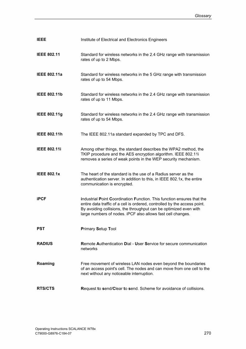
Glossary
Operating Instructions SCALANCE W78x C79000-G8976-C184-07 270
IEEE Institute of Electrical and Electronics Engineers
IEEE 802.11 Standard for wireless networks in the 2.4 GHz range with transmission rates of up to 2 Mbps.
IEEE 802.11a Standard for wireless networks in the 5 GHz range with transmission rates of up to 54 Mbps.
IEEE 802.11b Standard for wireless networks in the 2.4 GHz range with transmission rates of up to 11 Mbps.
IEEE 802.11g Standard for wireless networks in the 2.4 GHz range with transmission rates of up to 54 Mbps.
IEEE 802.11h The IEEE 802.11a standard expanded by TPC and DFS.
IEEE 802.11i Among other things, the standard describes the WPA2 method, the TKIP procedure and the AES encryption algorithm. IEEE 802.11i removes a series of weak points in the WEP security mechanism.
IEEE 802.1x The heart of the standard is the use of a Radius server as the authentication server. In addition to this, in IEEE 802.1x, the entire communication is encrypted.
iPCF industrial Point Coordination Function. This function ensures that the entire data traffic of a cell is ordered, controlled by the access point. By avoiding collisions, the throughput can be optimized even with large numbers of nodes. iPCF also allows fast cell changes.
PST Primary Setup Tool
RADIUS Remote Authentication Dial - User Service for secure communication networks
Roaming Free movement of wireless LAN nodes even beyond the boundaries of an access point's cell. The nodes and can move from one cell to the next without any noticeable interruption.
RTS/CTS Request to send/Clear to send. Scheme for avoidance of collisions.

Glossary
Operating Instructions SCALANCE W78x C79000-G8976-C184-07 271
SSID Service Set Identifier (SSID) is used to identify a wireless network based on IEEE 802.11
SNMP Simple Network Management Protocol. Standardized protocol for transporting network management information.
TKIP Temporal Key Integrity Protocol. Scheme for cyclic changing of keys in WLANs.
TPC The Transmit-Power Control function (TPC) introduced as a supplementary function by the 802.11h expansion for 5 GHz components allows an automatic adaptation of the transmit power. Information on the attenuation values and the expected budget reserves in received power are taken into account. TPC is also intended to make sure that the maximum permitted transmit power of a channel specified by the relevant regulatory bodies is not exceeded by the component. TPC attempts to operate with the minimum transmit power between the communicating stations or between access point and station.
VAP Virtual Access Point. By using virtual access points, various SSIDs (maximum of 8 per WLAN interface) can be configured with different security settings. You can assign each virtual AP to a particular VLAN.
WBM Web Based Management. HTTP-based configuration method in which an HTTP server is used in the SCALANCE W78x.
WDS Wireless Distribution System. Radio links for connecting the access points for an extended service set (ESS)
WEP WEP (Wired Equivalence Privacy) is an optional part of the IEEE 802.11 standard. WEP specifies methods of authentication and encryption working with fixed keys stored on the device. All devices that want to access a network in which WEP is used must first be supplied with the same keys. WEP works with key lengths between 40 and 128 bits. Occasionally different key lengths are encountered (for example 256 bits) but these are not intended in the vendor-independent WLAN standards IEEE 802.11b and 802.11g. The keys can only be changed manually.
Wi-Fi Wireless Fidelity. The Wi-Fi Alliance is a group of WLAN manufacturers that tests and certifies the interoperability or WLAN products. Wi-Fi is a certification of WLANs according to 802.11b and is performed by the WECA of the WiFi parent organization. This certification confirms the interoperability of WLAN products operating

Glossary
Operating Instructions SCALANCE W78x C79000-G8976-C184-07 272
in compliance to the 802.11b standard. The Wi-Fi Alliance also develops standards. The WiFi Alliance has developed its own architectures for security procedures that have not yet been standardized such as the WiFi Protected Architecture (WPA) to be able to test the compatibility of the various manufacturers' products. For real-time transmission, the Wi-Fi Alliance has specified Wi-Fi Multimedia (WMM) for transmissions with guaranteed quality of service (QoS).
WMM Wi-Fi Multimedia
WPA WPA (Wi-Fi Protected Access) is a method specified by the Wi-Fi Alliance to close security gaps in WEP. Authentication using a server is stipulated (802.1x). The dynamic exchange of keys at each frame introduces further security. As the encryption method, you can choose between TKIP (Temporal Key Integrity Protocol) and AES (Advanced Encryption Standard). Although WPA never became an official component of the IEEE 802.11 family of standards, it has become very widespread in a short time. This, however, applies only to the WPA procedure described above using TKIP. The optional possible implementation of WPA on the basis of AES, on the other hand, did not become established and is therefore irrelevant in everyday practice. AES only took on practical value only with the development of the later WPA2 standard.
WPA-PSK WPA-PSK is a weakened form of WPA. In this method, authentication is not established by a server but is based on a password. This password must be configured manually on the client and server. Wherever possible, you should change to the WPA method to achieve greater security.

Operating Instructions SCALANCE W78x C79000-G8976-C184-07 273
Index
A ACL........................................................ 174 Ad Hoc networks ..................................... 14 Adopt MAC Address................................ 69 Antennas ......................................... 34, 151 ARP table .............................................. 192 Auth Log ................................................ 228 Authentication.................................. 84, 163
B Bandwidth reservation........................... 213 Basic Wizard...................................... 61, 63 Beacon .................................................. 149 Bridge .................................................... 180
C Channel Selection ................................... 72 CLI commands
shortcuts for commands .................... 102 symbolic representation..................... 103
Client List............................................... 230 Command Line Interface ....................... 102 C-PLUG........................................... 28, 136
D Decibel................................................... 261 DHCP server ......................................... 112 DLC protocol............................................ 48
installation............................................ 49
E E-mail .................................................... 121 Encryption........................................ 86, 165
F Forward delay........................................ 195
H Hello Time ............................................. 195 Help function.......................................... 101 HiPath.................................................... 106 HTTPS..................................................... 60 Hybrid cable............................................. 35
I IEEE 802.11a .......................................... 23
IEEE 802.11b...........................................23 IEEE 802.11g...................................23, 157 IEEE 802.11h...........................................23 IP address................................................63 IP, TCP/IP, ICMP, SNMP ......................242 IP-Alive...................................................224 iPCF .................................................93, 215 iPCF Wizard.......................................61, 93 iQoS .......................................................238 iQoS .......................................................213
L Learning Table .......................................192 LED simulation.......................................100 Lightning Protection .................................31 Link Check .............................................220 Locale setting.........................................104 Log table ................................................227 Losses....................................................264
M MAC filter ...............................................210 Max Age.................................................195 Multichannel configuration .......................16
N NAT........................................................203 New........................................................101
O Overlap AP.............................................236
P Password .................................................76 Path cost ................................................197 Power specifications ..............................262 Power Supply...........................................33 PRESET PLUG........................................44 Primary Setup Tool
Installation ............................................51 via command line .................................56
Priority....................................................196 Protocol filter ..........................................212
R RADIUS ...........................................88, 178

Index
Operating Instructions SCALANCE W78x C79000-G8976-C184-07 274
Receiver sensitivity................................ 266 Redundant connection .......................... 222 Refresh .................................................. 101 RTS/CTS ....................................... 149, 152
S Save
Device data........................................ 132 Security settings ...................................... 79 Security Wizard ................................. 61, 75 Set values.............................................. 101 SNMP .................................................... 122 SNTP..................................................... 130 Spanning Tree............................... 192, 240 Spanning tree port parameters.............. 196 SSID ........................................................ 80 Standalone configuration......................... 13 Storm threshold ..................................... 202
Suppress SSID broadcasting.................167
T Transmit power ......................................149 TTL.........................................................112
V Versions .................................................229
W WDS.......................................................181 Web Based Management ........................57 WEP.........................................................87 Wireless access .......................................15 Wizards ....................................................57 WPA.......................................................167 WPA2.......................................................90