Embed Size (px)
Citation preview

8/20/2019 Communication With Simatic Net
http://slidepdf.com/reader/full/communication-with-simatic-net 1/200
SIMATIC
Communication with SIMATIC
Manual
1 Introduction and Basics of Communication
2 Communication Services
3 Communication Networks
4 Communication Functions for S7-300/400
5 Communication Functions for M7-300/400
6 Cyclic Communication for S7/M7/C7-300/400
7 Communication Functions on PCs
8 Connecting SIMATIC Programming Devices/OPs
9 Project Engineering and Configuring with STEP 7
10 Programming Examples
Appendix
Glossary
6ES7 398-8EA00-8BA0 Edition 2
SIMATIC is a trademark of Siemens
Siemens Aktiengesellschaft
8/20/2019 Communication With Simatic Net
http://slidepdf.com/reader/full/communication-with-simatic-net 2/200
Wir haben den Inhalt der Druckschrift auf Übereinstim-mung mit der beschriebenen Hard- und Software geprüft.Dennoch können Abweichungen nicht ausgeschlossenwerden, so daß wir für die vollständige Übereinstimmungkeine Gewähr übernehmen. Die Angaben in der Druck-
schrift werden jedoch regelmäßig überprüft. NotwendigeKorrekturen sind in den nachfolgenden Auflagen enthalten.Für Verbesserungsvorschläge sind wir dankbar.
Technische Änderungen vorbehalten.
Weitergabe sowie Vervielfältigung dieser Unterlage,Verwertung und Mitteilung ihres Inhalts nicht gestattet,soweit nicht ausdrücklich zugestanden. Zuwiderhandlun-gen verpflichten zu Schadenersatz. Alle Rechte vorbehal-ten, insbesondere für den Fall der Patenterteilung oder
GM-Eintragung.
Copyright © Siemens AG 1997All Rights Reserved
We have checked the contents of this manual for agree-ment with the hardware described. Since deviations cannotbe precluded entirely, we cannot guarantee full agreement.However, the data in this manual are reviewed regularlyand any necessary corrections included in subsequenteditions. Suggestions for improvement are welcome.
Technical data subject to change.
The reproduction, transmission or use of this document orits contents are not permitted without express writtenauthority. Offenders will be liable for damages. All rights,including rights created by patent grant or registration of autility or design, are reserved.
Copyright © Siemens AG 1997
All Rights Reserved
Nous avons vérifié la conformité du contenu du présentmanuel avec le matériel et le logiciel qui y sont décrits. Or,des divergences n'étant pas exclues, nous ne pouvons pasnous porter garants pour la conformité intégrale. Si l'usagedu manuel devait révéler des erreurs, nous en tiendronscompte et apporterons les corrections nécessaires dès laprochaine édition. Veuillez nous faire part de vos sugges-tions.
Nous nous réservons le droit de modifier les caractéristi-ques techniques.
Toute communication ou reproduction de ce support d'in-formations, toute exploitation ou communication de soncontenu sont interdites, sauf autorisation expresse. Toutmanquement à cette règle est illicite et expose son auteurau versement de dommages et intérêts. Tous nos droitssont réservés, notamment pour le cas de la délivrance d'unbrevet ou celui de l'enregistrement d'un modèle d'utilité.
Copyright © Siemens AG 1997All Rights Reserved
Siemens Aktiengesellschaft Electronics Factory, KarlsruhePrinted in the Federal Republic of Germany

8/20/2019 Communication With Simatic Net
http://slidepdf.com/reader/full/communication-with-simatic-net 3/200
SIMATIC
Communication with SIMATIC
Manual

8/20/2019 Communication With Simatic Net
http://slidepdf.com/reader/full/communication-with-simatic-net 4/200
Note
The contents of this manual shall not become part of or modify any prior or existing agreement, commitment or relationship. TheSales Contract contains the entire obligations of Siemens. The warranty contained in the contract between the parties is the solewarranty of Siemens. Any statements contained herein do not create new warranties or modify the existing warranty.
For the sake of clarity, this document cannot cover all conceivable cases regarding the operation of this equipment. Should yourequire further information or face special problems that have not been dealt with in sufficient detail in this document, please contactyour local Siemens office.
General information
This equipment is driven by electricity. Hazardous voltages are present in this electrical equipment during
operation.
WARNING !
Non-observance of the safety instructions can result in severe personal injury and/or property damage.
Only qualified personnel should work on or around this equipment. These persons must be fully conversantwith all safety instructions and maintenance measures contained herein.
This equipment will function correctly and safely only if it is transported, stored and installed as intended andoperated and maintained with care.
Requirements concerning qualified personnel
For the purpose of this manual and product labels, a "qualified person" is one who is familiar with the installation, assembly, start-up
and operation of the equipment. In addition, s/he has the following qualifications:− Is trained and authorized to energize, de-energize, ground and tag circuits and equipment or systems in accordance with up-to-
date established safety practices
− Is trained in the proper care and use of protective equipment in accordance with up-to-date established safety practices.
!

8/20/2019 Communication With Simatic Net
http://slidepdf.com/reader/full/communication-with-simatic-net 5/200
Communication with SIMATICEWA 4NEB 710 6075-02a I
Preliminary Remarks
Purpose of thisManual
This manual provides an overview of communication in SIMATICS7/M7/C7 with the following content:
• Introduction to communication and explanation of terms used. In thisintroduction to the theoretical aspect of communication, you will dis-cover how we define communication for the purpose of this manual.
• Description of the communication services and their software inter-faces to the separate communication partners. In this part of themanual you will find out which communication services you can useon the various communication networks. After reading this chapter,you will be able to select the communication possibilities that aresuitable for your application.
• Establishing communication networks and configuring the communi-cation functions. This manual contains a brief introduction to estab-lishing and configuring communication networks.
• ExamplesProgram examples are provided for the different communicationpossibilities and you will also find out in which software package theyare supplied.
Readership This manual has been written for planning and project engineers as well asprogrammers who are concerned with planning and configuring communi-cation services for the SIMATIC systems.
The manual is equally suited to beginners and communication experts.

8/20/2019 Communication With Simatic Net
http://slidepdf.com/reader/full/communication-with-simatic-net 6/200
Communication with SIMATICII EWA 4NEB 710 6075-02a
Where to Start inthis Manual
Where can you find the information that you want in this manual?
You are looking for the followinginformation.....
.....you can find this information inChapter
You would like to know more aboutcommunication
Chapter 1Introduction and Basics of Communi-cation
You know all about communicationand need to know about the pos-sibilities with SIMATIC
Chapter 2Communication Services
Chapter 3Communication Networks
Chapter 4Communication Functions forS7-300/400
Chapter 5Communication Functions forM7-300/400
Chapter 6Cyclic Communication forS7/M7/C7-300/400
Appendix
You want to expand an existingnetwork
Chapter 3Communication Networks
Appendix
You already have the hardwareand need to know about pro-
gramming/configuring or whichsoftware tools will provide the nec-essary support
Chapter 9Project Engineering and Configuring
with STEP 7
You are looking for examples Chapter 10Programming Examples
You need detailed information onthe hardware components or soft-ware
Appendix
STEP 7 Documentation
You require information on theperformance features
Appendix

8/20/2019 Communication With Simatic Net
http://slidepdf.com/reader/full/communication-with-simatic-net 7/200
Communication with SIMATICEWA 4NEB 710 6075-02a III
Finding Your Way Rapid access to specific information is supported in this manual by thefollowing directories:
• A complete list of contents is included at the beginning of this man-ual.
• In each chapter, a heading in the left-hand column on every pageprovides an overview of the contents of the paragraph.
• A glossary follows the appendices, with explanations of importanttechnical terms used in the manual.
Scope of thisManual
This manual describes the communication functions that you can programand configure using the following software packages:
• STEP 7, V3.1 upwards
• NCM S7 for PROFIBUS, V3.1 upwards
• NCM S7 for Industrial Ethernet, V3.1 upwards
An extensive overview of all communication functions can be found in theappendix.

8/20/2019 Communication With Simatic Net
http://slidepdf.com/reader/full/communication-with-simatic-net 8/200
Communication with SIMATICIV EWA 4NEB 710 6075-02a
Location in theCommunicationLandscape
The "Communication with SIMATIC" manual provides an introduction toand overview of the communication possibilities that SIMATIC offers.Comprehensive user documentation is available for SIMATIC describing:
• the hardware
• configuration and programming of a SIMATIC system.
Figure 0-1 provides an overview of the SIMATIC documentation land-scape.
In these manuals, you will find extensive information on the hardware ofthe communication partners and on configuring and programming. Supportis also available in STEP 7 and NCM S7 via the online help function.
Program-mingManual
Manual
Communication
with SIMATIC
System Software forS7-300/400
Program Design
STEP 7 User andReference ManualsM7 Basis Software
Hardware Manuals- S7-200- S7/M7-300/400- ET 200- SIMATIC NET
Manual
ManualManual
SIMATIC NET
Manuals forNCM S7 Profibus/ Industrial Ethernet
Figure 0-1Documentation Landscape for SIMATIC
8/20/2019 Communication With Simatic Net
http://slidepdf.com/reader/full/communication-with-simatic-net 9/200
Communication with SIMATICEWA 4NEB 710 6075-02a V
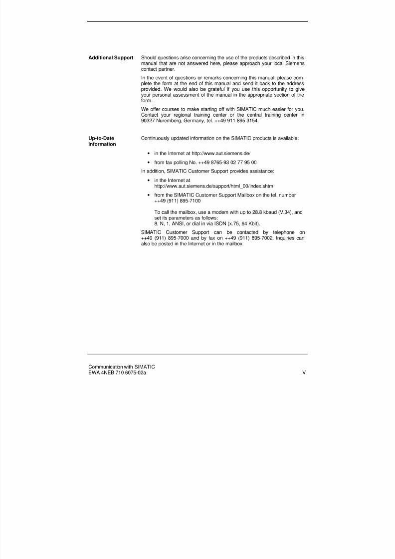
Additional Support Should questions arise concerning the use of the products described in thismanual that are not answered here, please approach your local Siemenscontact partner.
In the event of questions or remarks concerning this manual, please com-plete the form at the end of this manual and send it back to the addressprovided. We would also be grateful if you use this opportunity to giveyour personal assessment of the manual in the appropriate section of theform.
We offer courses to make starting off with SIMATIC much easier for you.Contact your regional training center or the central training center in90327 Nuremberg, Germany, tel. ++49 911 895 3154.
Up-to-DateInformation
Continuously updated information on the SIMATIC products is available:
• in the Internet at http://www.aut.siemens.de/
• from fax polling No. ++49 8765-93 02 77 95 00
In addition, SIMATIC Customer Support provides assistance:
• in the Internet athttp://www.aut.siemens.de/support/html_00/index.shtm
• from the SIMATIC Customer Support Mailbox on the tel. number++49 (911) 895-7100
To call the mailbox, use a modem with up to 28.8 kbaud (V.34), andset its parameters as follows:8, N, 1, ANSI, or dial in via ISDN (x.75, 64 Kbit).
SIMATIC Customer Support can be contacted by telephone on++49 (911) 895-7000 and by fax on ++49 (911) 895-7002. Inquiries canalso be posted in the Internet or in the mailbox.

8/20/2019 Communication With Simatic Net
http://slidepdf.com/reader/full/communication-with-simatic-net 10/200

8/20/2019 Communication With Simatic Net
http://slidepdf.com/reader/full/communication-with-simatic-net 11/200
Communication with SIMATICEWA 4NEB 710 6075-02a 1-1
Contents
1 Introduction and Basics of Communication ...................................................... ..................1-1
1.1 Basic Terminology ................................................................................................................1-21.2 Network Topology.................................................................................................................1-51.3 Classification of Networks.....................................................................................................1-81.4 Access Techniques...............................................................................................................1-91.5 Client/Server Concept.........................................................................................................1-111.6 Links...................................................................................................................................1-121.6.1 Class of Link ....................................................................................................................1-141.6.2 Link Types .......................................................................................................................1-151.6.3 Link Resources ................................................................................................................1-161.7 ISO Reference Model .........................................................................................................1-171.8 Coupled Networks...............................................................................................................1-211.9 Reliability of Transmission ..................................................................................................1-251.10 Application Areas for the Subnets ..................................................................................... 1-26
2 Communication Services ......................................................... .............................................2-12.1 Introduction...........................................................................................................................2-22.2 S7 Functions.........................................................................................................................2-42.3 ISO Transport Services.........................................................................................................2-62.4 ISO-on-TCP Services ...........................................................................................................2-72.5 PROFIBUS-FDL Services.....................................................................................................2-82.6 PROFIBUS-FMS Services....................................................................................................2-92.7 PROFIBUS-DP Services.....................................................................................................2-102.8 Global Data Communication (GD).......................................................................................2-112.9 AS-i Services......................................................................................................................2-12
3 Communication Networks.....................................................................................................3-13.1 Overview ..............................................................................................................................3-2
3.2 Multipoint Interface (MPI)......................................................................................................3-53.3 PROFIBUS...........................................................................................................................3-73.4 Industrial Ethernet............................................................................................................... 3-123.5 Point-to-Point Link ..............................................................................................................3-143.6 AS-Interface........................................................................................................................3-16
4 Communication Functions for S7-300/400...........................................................................4-14.1 Introduction...........................................................................................................................4-24.2 Communication SFCs for Non-Configured S7 Links..............................................................4-34.2.1 Communication via MPI Subnets.......................................................................................4-44.2.2 Communication Within an S7 Station................................................................................. 4-64.3 Communication SFBs for Configured S7 Links......................................................................4-84.4 SEND/RECEIVE Interface .................................................................................................. 4-134.5 FMS Interface.....................................................................................................................4-15
4.6 Communication via Point-to-Point Links..............................................................................4-185 Communication Functions for M7-300/400 ..........................................................................5-15.1 Communication Functions for Non-Configured S7 Links .......................................................5-25.2 Communication Functions for Configured S7 Links...............................................................5-5

8/20/2019 Communication With Simatic Net
http://slidepdf.com/reader/full/communication-with-simatic-net 12/200
Communication with SIMATIC1-2 EWA 4NEB 710 6075-02a
6 Cyclic Communication for S7/M7/C7-300/400 ......................................................................6-16.1 Introduction...........................................................................................................................6-26.2 Global Data Communication (GD).........................................................................................6-36.3 Distributed I/O via PROFIBUS-DP........................................................................................6-76.4 Distributed I/O via the AS-i bus.............................................................................................6-9
7 Communication Functions on PCs.......................................................................................7-17.1 Communication Functions for Configured S7 Links (SAPI-S7) ..............................................7-27.2 PC Interface for SEND/RECEIVE .........................................................................................7-5
8 Connecting SIMATIC Programming Devices/OPs............................................ ....................8-18.1 Programming Device/PC Interfacing for STEP 7 on Subnets................................................ 8-28.2 SIMATIC OP Interface to Subnets ........................................................................................8-48.3 TeleService ..........................................................................................................................8-6
9 Project Engineering and Configuring with STEP 7 ............................................................. 9-19.1 S7 Project.............................................................................................................................9-29.2 Specifying the Network Configuration ...................................................................................9-39.3 Address Assignment .............................................................................................................9-59.3.1 Address Assignment via MPI .............................................................................................9-5
9.3.2 Address Assignment via PROFIBUS..................................................................................9-69.3.3 Address Assignment via Ethernet.......................................................................................9-79.4 Link Resources ..................................................................................................................... 9-89.5 Configuring Links................................................................................................................9-139.5.1 Special Case of the Point-to-Point Link ............................................................................ 9-169.5.2 Links to Non-S7 Stations..................................................................................................9-17
10 Programming Examples ........................................................ ............................................ 10-110.1 Communication with SFCs................................................................................................ 10-210.2 Communication with SFBs................................................................................................ 10-410.3 Communication with FDL between SIMATIC S7s.............................................................. 10-710.4 Communication with FDL - SIMATIC S7 and S5 ...............................................................10-910.5 DP Communication via CPs............................................................................................10-11
10.6 Communication with ISO Transport between SIMATIC S7s ............................................ 10-1210.7 Communication with ISO Transport - SIMATIC S7 and S5 ..............................................10-14
A Appendix............................................................................................................................... A-1A.1 Communications Matrix....................................................................................................... A-2A.1.1 MPI Subnet ...................................................................................................................... A-3A.1.2 PROFIBUS Subnet........................................................................................................... A-6A.1.3 Industrial Ethernet ............................................................................................................ A-9A.2 Technical Data .................................................................................................................. A-13A.2.1 SIMATIC S7-200 ............................................................................................................ A-13A.2.2 SIMATIC S7-300 ............................................................................................................ A-14A.2.3 SIMATIC S7-400 ............................................................................................................ A-16A.2.4 SIMATIC M7-300/400..................................................................................................... A-18A.3 Performance Data ............................................................................................................. A-19A.3.1 Response Time for Communication SFBs via Configured S7 Links ................................ A-19

8/20/2019 Communication With Simatic Net
http://slidepdf.com/reader/full/communication-with-simatic-net 13/200
Introduction and Basics of Communication
Communication with SIMATICEWA 4NEB 710 6075-02a 1-1
1 Introduction and Basics of Communication
Overview In this chapter you will find out what we mean by communication withinthe context of SIMATIC. You will become familiar with the most importantterms and will find out where communication takes place from the view-point of the user.
Chapter Overview In Section You will find On page
1.1 Basic Terminology 1-2
1.2 Network Topology 1-5
1.3 Classification of Networks 1-8
1.4 Access Techniques 1-9
1.5 Client/Server Concept 1-11
1.6 Links 1-12
1.7 ISO Reference Model 1-17
1.8 Coupled Networks 1-21
1.9 Reliability of Transmission 1-25
1.10 Application Areas for the Subnets 1-26

8/20/2019 Communication With Simatic Net
http://slidepdf.com/reader/full/communication-with-simatic-net 14/200
Introduction and Basics of Communication
Communication with SIMATICEWA 4NEB 710 6075-02a1-2
1.1 Basic Terminology
Overview The basic terminology and principles of communication that are importantfor information transfer between controllers and between controllers andOPs/PCs will be explained here.
Communication Communication involves the transmission of data between two communi-cation partners of different types, controlling the communication partnerand querying the operating status of the communication partner. Commu-nication can take place via different communication routes.
Figure 1-1: Example of Communication Partners in a Subnet
CommunicationPartner
A communication partner is a module that is capable of performing com-munication functions, i.e. exchanging data. The physical location of thecommunication partner can either be within the same unit or in anotheritem of equipment. Examples of communication partners are CPUs orFMs.
Station A station is a device which as a self-contained unit (e.g. programmablecontroller, programming device, operator panel/system, PC or non-Siemens unit) can be connected to one or more subnets.
Subnet The subnet is the sum total of all physical components that are required inorder to build up a data transmission route as well as the associated com-mon procedures required for transferring data.
The interconnections between stations connected to a subnet do not passthrough gateways. The physical entirety of a subnet (MPI, PROFIBUS,Industrial Ethernet) is also designated as a transmission medium.
CPUCPU
Station
Station Module withcommunicationcapability
Module withcommunicationcapability
FM
Subnetwork
CPUCPU FM

8/20/2019 Communication With Simatic Net
http://slidepdf.com/reader/full/communication-with-simatic-net 15/200
Introduction and Basics of Communication
Communication with SIMATICEWA 4NEB 710 6075-02a 1-3
Network A network is a unit which comprises one or more interconnected subnetsof the same or different type. It comprises all stations that are able tocommunicate with one another.
Figure 1-2: Example of a Communication Network
Link A link is the logical assignment (via configuration) of one communicationpartner to another for the purpose of executing a specific communicationservice. The link is directly assigned to a communication service.
The link has two end points which contain the information required foraddressing the communication partner as well as further attributes for es-tablishing the link (see Section 1.6). The communication functions onlyuse the local end point for link reference purposes.
CommunicationFunctions
These are the functions offered by a software interface which utilizecommunication services. Communication functions can transfer data be-tween communication partners that have different performance data,control the communication partner (e.g. switch it to the STOP state) orquery its current operating status.
CommunicationServices andSoftwareInterfaces
This term describes the communication functions using defined perform-ance features, such as data to be transferred, devices to be controlled,devices to be monitored and programs to be loaded. The communicationservices (simply referred to as services from now on) are offered via
software interfaces in the data terminal (e.g. SIMATIC S7 system func-tions). The communication services can be classified with respect to theirperformance in accordance with the ISO reference model (see Section1.7).
Network
Subnet 3
Subnet 2
Subnet 1
Station

8/20/2019 Communication With Simatic Net
http://slidepdf.com/reader/full/communication-with-simatic-net 16/200
Introduction and Basics of Communication
Communication with SIMATICEWA 4NEB 710 6075-02a1-4
A software interface does not necessarily offer all the communicationfunctions of a service. The communication service can be provided in therespective data terminal (e.g. PLC, PC) using various software interfaces.
Protocol This is a bit-specific arrangement between two communication partnersfor the purpose of executing a specific communication service. The proto-col defines the structure of the contents of the data traffic on the physicalcable and specifies, for example, the operating mode, procedure for es-tablishing a link, data backup and transmission rate.
Data Consistency The extent of the data area that cannot be modified by competing proc-esses simultaneously is termed the data consistency. Data areas that arelarger than the data consistency can therefore become inconsistent as awhole. This means that a self-contained data area (larger than the dataconsistency) can comprise new and old consistent data blocks at any onetime.

8/20/2019 Communication With Simatic Net
http://slidepdf.com/reader/full/communication-with-simatic-net 17/200
Introduction and Basics of Communication
Communication with SIMATICEWA 4NEB 710 6075-02a 1-5
1.2 Network Topology
Overview The term topology refers to the different structures found within a subnet(e.g. tree, ring).
When a number of autonomous automation system components such assensors, actuators or PLCs exchange information, they must be physicallyinterconnected in some form of structure. In this manner they form acommunication network. The network topology is the basic geometricstructure of the network. The communication stations are the nodes of thenetwork. They are linked by junctions. The simplest structure is obtainedwhen the network comprises just two communication stations, i.e. twonodes. This is the simplest structure, known as a point-to-point structure.
Line The simplest geometrical form is a line structure. It is often called a bus
structure, even though a bus does not necessarily have a line structure. Inthis case, all stations on the network only require one interface. They canbe linked with the main line via short tapped lines.
Whereas in a point-to-point structure, four nodes for example can com-municate simultaneously in pairs, this is not possible in a line structure. Ithas to be ensured that only one station is able to transmit at a time, duringwhich all other stations are only permitted to listen. This means that rulesare necessary to define when a station has the right to transmit. Bus ac-cess techniques are important here. They are also necessary for the othertopologies described below.
Station 2 Station 3Station 1
Figure 1-3: Example of Line Topology
8/20/2019 Communication With Simatic Net
http://slidepdf.com/reader/full/communication-with-simatic-net 18/200
Introduction and Basics of Communication
Communication with SIMATICEWA 4NEB 710 6075-02a1-6
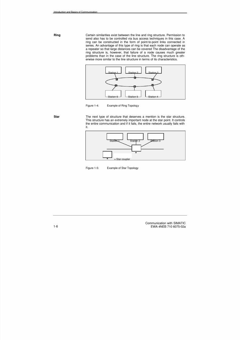
Ring Certain similarities exist between the line and ring structure. Permission tosend also has to be controlled via bus access techniques in this case. Aring can be constructed in the form of point-to-point links connected in
series. An advantage of this type of ring is that each node can operate asa repeater so that large distances can be covered The disadvantage of thering structure is, however, that failure of a node causes much greaterproblems than in the case of the line structure. The ring structure is oth-erwise more similar to the line structure in terms of its characteristics.
Station 2 Station 3Station 1
Station 5 Station 4Station 6
Figure 1-4: Example of Ring Topology
Star The next type of structure that deserves a mention is the star structure.This structure has an extremely important node at the star point. It controlsthe entire communication and if it fails, the entire network usually fails withit.
Station 2 Station 3Station 1
= Star coupler
**
Figure 1-5: Example of Star Topology
8/20/2019 Communication With Simatic Net
http://slidepdf.com/reader/full/communication-with-simatic-net 19/200
Introduction and Basics of Communication
Communication with SIMATICEWA 4NEB 710 6075-02a 1-7
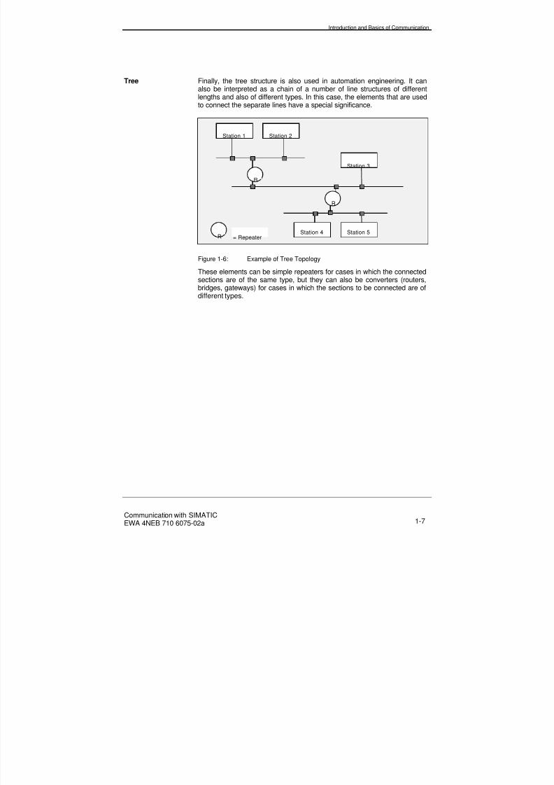
Tree Finally, the tree structure is also used in automation engineering. It canalso be interpreted as a chain of a number of line structures of differentlengths and also of different types. In this case, the elements that are used
to connect the separate lines have a special significance.
Station 2
Station 3
Station 1
R
R = RepeaterStation 5Station 4
R
Figure 1-6: Example of Tree Topology
These elements can be simple repeaters for cases in which the connectedsections are of the same type, but they can also be converters (routers,bridges, gateways) for cases in which the sections to be connected are ofdifferent types.
8/20/2019 Communication With Simatic Net
http://slidepdf.com/reader/full/communication-with-simatic-net 20/200
Introduction and Basics of Communication
Communication with SIMATICEWA 4NEB 710 6075-02a1-8
1.3 Classification of Networks
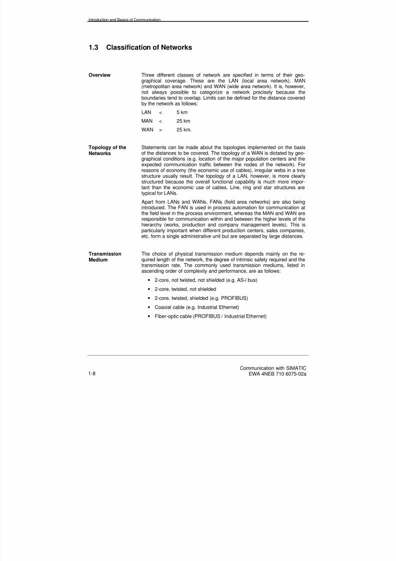
Overview Three different classes of network are specified in terms of their geo-graphical coverage. These are the LAN (local area network), MAN(metropolitan area network) and WAN (wide area network). It is, however,not always possible to categorize a network precisely because theboundaries tend to overlap. Limits can be defined for the distance coveredby the network as follows:
LAN < 5 km
MAN < 25 km
WAN > 25 km.
Topology of the
Networks
Statements can be made about the topologies implemented on the basis
of the distances to be covered. The topology of a WAN is dictated by geo-graphical conditions (e.g. location of the major population centers and theexpected communication traffic between the nodes of the network). Forreasons of economy (the economic use of cables), irregular webs in a treestructure usually result. The topology of a LAN, however, is more clearlystructured because the overall functional capability is much more impor-tant than the economic use of cables. Line, ring and star structures aretypical for LANs.
Apart from LANs and WANs, FANs (field area networks) are also beingintroduced. The FAN is used in process automation for communication atthe field level in the process environment, whereas the MAN and WAN areresponsible for communication within and between the higher levels of thehierarchy (works, production and company management levels). This isparticularly important when different production centers, sales companies,etc. form a single administrative unit but are separated by large distances.
TransmissionMedium
The choice of physical transmission medium depends mainly on the re-quired length of the network, the degree of intrinsic safety required and thetransmission rate. The commonly used transmission mediums, listed inascending order of complexity and performance, are as follows:
• 2-core, not twisted, not shielded (e.g. AS-i bus)
• 2-core, twisted, not shielded
• 2-core, twisted, shielded (e.g. PROFIBUS)
• Coaxial cable (e.g. Industrial Ethernet)
• Fiber-optic cable (PROFIBUS / Industrial Ethernet)

8/20/2019 Communication With Simatic Net
http://slidepdf.com/reader/full/communication-with-simatic-net 21/200
Introduction and Basics of Communication
Communication with SIMATICEWA 4NEB 710 6075-02a 1-9
1.4 Access Techniques
Overview Since only one telegram can be transmitted at any one time on a bus,there has to be a system to determine which bus station is permitted totransmit on the bus. The number of "listening" telegram receivers is notimportant. Access to the bus is controlled by the bus access technique.There are different categories of bus access techniques: central and de-centralized, whereby the latter is subdivided into deterministic and sto-chastic (or random) techniques:
Access technique
Central Decentral
Deterministic Stochastic
Figure 1-7: Bus Access Techniques
Master/Slave A typical central technique is the master/slave technique. The master di-rects the entire bus traffic. It sends data to the slaves (polling) and givesthe slaves the command to send. Direct communication between slaves is
usually not possible. The advantage of master/slave techniques is thesimple and therefore efficient bus control. This is why they are often usedin field buses such as PROFIBUS-DP.
Figure 1-8: Example of a Master/Slave Configuration
Master/slave assignment
Bus s stem
SlaveSlave Slave
Master
8/20/2019 Communication With Simatic Net
http://slidepdf.com/reader/full/communication-with-simatic-net 22/200
Introduction and Basics of Communication
Communication with SIMATICEWA 4NEB 710 6075-02a1-10
Token Passing Token passing is a decentralized, deterministic technique. In this case, atoken (fixed bit pattern) travels through the communication network as asign of permission to send. The station in possession of the token is per-
mitted to send, but must pass the token on within a specified time limit.This guarantees that a maximum token circulation time is not exceeded. Ifthis technique is used in a line topology, the network is often described asa token bus. The token is passed from station to station in a logical ring inaccordance with certain rules. If the network is physically in the form of aring, it is called a token ring.
If several masters and slaves are configured in a communication network,only the masters receive the token.
CSMA/CD The most important stochastic (random) access technique is CSMA/CD(carrier sense multiple access with collision detection, standardized inIEEE 802.3). In this case, any station is permitted to send at any time,
provided that no other station is transmitting. Conflict occurs, however, asa result of signal runtimes when two stations start to transmit at the sametime because the bus was free. In this case, both stations detect the colli-sion by monitoring, stop transmitting and try again after a random waitingtime. Buses that use CSMA/CD (e.g. Industrial Ethernet) usually operate ata transmission rate of 10 Mbits/s.
8/20/2019 Communication With Simatic Net
http://slidepdf.com/reader/full/communication-with-simatic-net 23/200
Introduction and Basics of Communication
Communication with SIMATICEWA 4NEB 710 6075-02a 1-11
1.5 Client/Server Concept
Overview Client/server concepts are based on the principle of separating the func-tions of using (client) and managing (server) data. The aim of separatingthese functions is higher productivity in user program development as aresult of clear task definition, easier integration of different applicationsand better access to data from a large number of work stations. Mail serv-ers and communication servers are available for the purpose of properlyorganizing efficient access to services for a large number of users(clients).
Server It is the responsibility of the server to store and manage the data and toensure that special functions are available (e.g. communication services).
The communication functions of the server do not have to execute in the
user program, but can also be implemented in the operating system (e.g.order confirmation PUT/GET services).
Client The responsibility of the client is to make it easier for the end user to beable to access the overall system without the need for the detailed distri-bution of data and functions to be visible.
Model In the field of automation applications, the interactions between applica-tions and the services provided by the communication system can often bedescribed in the form of the client/server model. In this case, the applica-tion that behaves like a client (e.g. PUT/GET) requests a service and the
server (e.g. programmable controller) provides the service. Information isusually exchanged via so-called communication objects. There are differ-ent types of communication objects with different attributes (e.g. data type,access right) and available operations. A client executes, for example, the"read" operation on a server object of the "variable" type.
Note The term „server“ is not a synonym for "slave". The concept of a server isbased on a Layer 7 view and the concept of a slave is based on a Layer 2view. A station that only has the functional scope of a slave is not able tosend on its own initiative. If an event occurs (e.g. transition to the STOPstate), a server, however, is able to send an appropriate signal via the bus.
8/20/2019 Communication With Simatic Net
http://slidepdf.com/reader/full/communication-with-simatic-net 24/200
Introduction and Basics of Communication
Communication with SIMATICEWA 4NEB 710 6075-02a1-12
1.6 Links
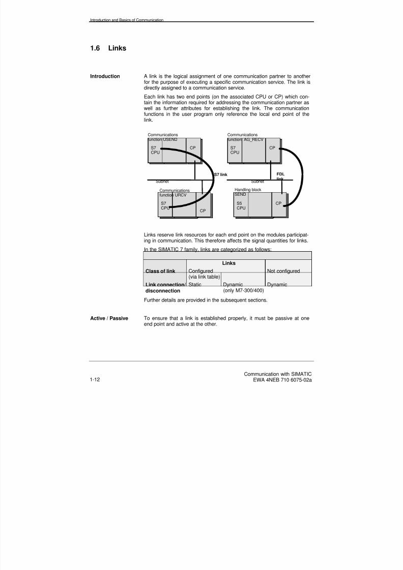
Introduction A link is the logical assignment of one communication partner to anotherfor the purpose of executing a specific communication service. The link isdirectly assigned to a communication service.
Each link has two end points (on the associated CPU or CP) which con-tain the information required for addressing the communication partner aswell as further attributes for establishing the link. The communicationfunctions in the user program only reference the local end point of thelink.
S7
CPU
Subnet
CP
S7CPU
CP
S7 link
Communicationsfunction USEND
Communicationsfunction URCV
S5CPU
CP
Handling blockSEND
S7
CPU
CP
Communicationsfunction AG_RECV
FDLlinkSubnet
Links reserve link resources for each end point on the modules participat-ing in communication. This therefore affects the signal quantities for links.
In the SIMATIC 7 family, links are categorized as follows:
Links
Class of link Configured(via link table)
Not configured
Link connection/disconnection
Static Dynamic(only M7-300/400)
Dynamic
Further details are provided in the subsequent sections.
Active / Passive To ensure that a link is established properly, it must be passive at oneend point and active at the other.

8/20/2019 Communication With Simatic Net
http://slidepdf.com/reader/full/communication-with-simatic-net 25/200
Introduction and Basics of Communication
Communication with SIMATICEWA 4NEB 710 6075-02a 1-13
Static Static links are used when sufficient link resources are available in theindividual stations of a system configuration and they do not have to bereleased again. Time-consuming connecting and disconnecting of links do
not have to be taken into account on planning either.Static links are established once only and are then permanent.
Dynamic Dynamic links are used to exchange data in sequence with differentcommunication partners or for the purpose of using existing link resourcesmore efficiently.
The actual connecting and disconnecting of links does not take placewhen the station starts up, but only in response to an explicit request fromthe user program.
It is therefore essential that the time involved in connecting and discon-necting links is taken into account in the case of time-critical processes.

8/20/2019 Communication With Simatic Net
http://slidepdf.com/reader/full/communication-with-simatic-net 26/200
Introduction and Basics of Communication
Communication with SIMATICEWA 4NEB 710 6075-02a1-14
1.6.1 Class of Link
Use Depending on the software interface used, the associated communicationfunctions require either configured or non-configured links (see Chapter2).
Configured Links This type of link is configured using STEP 7 (in the link table), whereby alocal ID is assigned to the respective link end point. This local ID is re-quired for parameterizing the communication functions. The local ID ref-erences a data area that also contains its own address information andthat of its communication partners.
Note Communication functions that originate from a SIMATIC OP or PC also
require configured links. In this case, however, the links are configuredusing a separate tool (e.g. ProTool or COML). These links also reservelink resources (for S7 functions) on the CPUs.
Non-ConfiguredLinks
Non-configured links are not configured via the link table in STEP 7.These links are established implicitly when the communication function iscalled and are removed if necessary when the data has been successfullytransmitted.

8/20/2019 Communication With Simatic Net
http://slidepdf.com/reader/full/communication-with-simatic-net 27/200
Introduction and Basics of Communication
Communication with SIMATICEWA 4NEB 710 6075-02a 1-15
1.6.2 Link Types
Definition The link establishes access to the communication service from the soft-ware interface. A link is directly allocated to a communication service. Forthis reason, a corresponding link type exists for each communicationservice.
In SIMATIC S7 the link types are allocated to services as follows (seeSection 2.1):
Service Link Type
S7 functions S7 link
ISO transport ISO transport link
ISO-on-TCP ISO-on-TCP link
FDL FDL linkFMS FMS link
Protocol drivere.g. RK512
Point-to-point link
The appropriate link type can be selected on configuring the links usingSTEP 7.
8/20/2019 Communication With Simatic Net
http://slidepdf.com/reader/full/communication-with-simatic-net 28/200
Introduction and Basics of Communication
Communication with SIMATICEWA 4NEB 710 6075-02a1-16
1.6.3 Link Resources
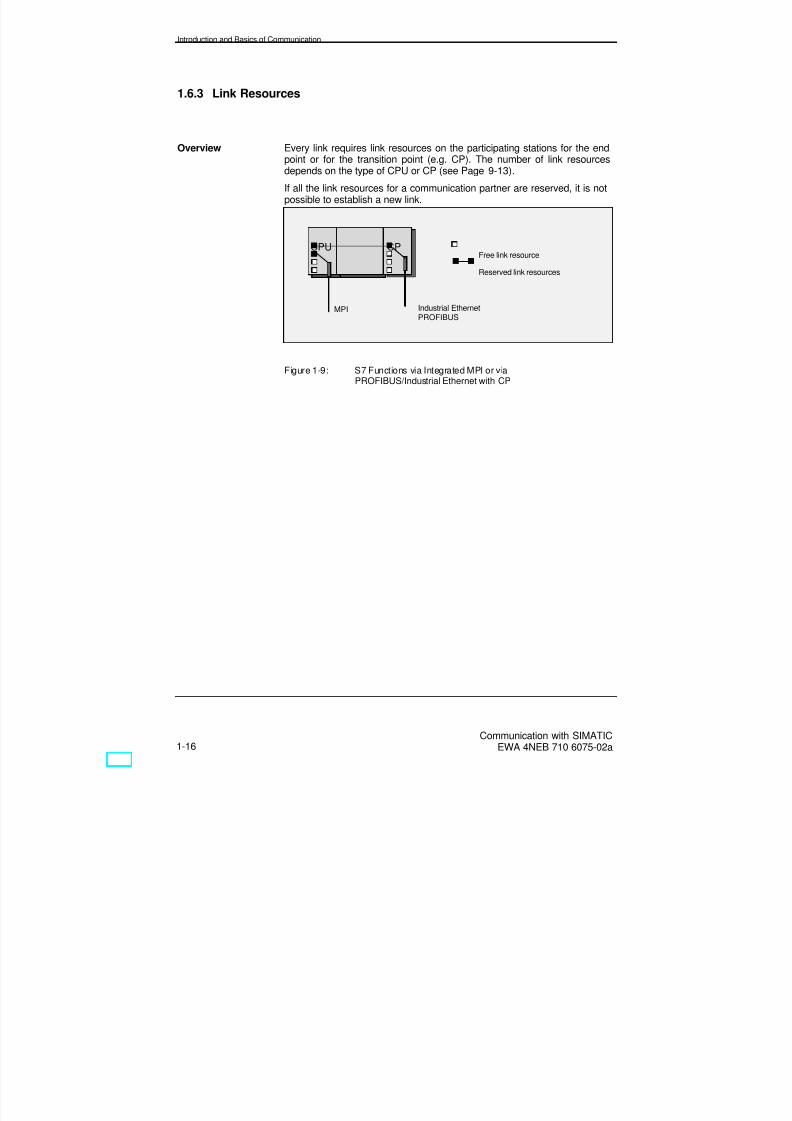
Overview Every link requires link resources on the participating stations for the endpoint or for the transition point (e.g. CP). The number of link resourcesdepends on the type of CPU or CP (see Page 9-13).
If all the link resources for a communication partner are reserved, it is notpossible to establish a new link.
Figure 1-9: S7 Functions via Integrated MPI or viaPROFIBUS/Industrial Ethernet with CP
CPU
MPI Industrial EthernetPROFIBUS
CPFree link resource
Reserved link resources

8/20/2019 Communication With Simatic Net
http://slidepdf.com/reader/full/communication-with-simatic-net 29/200
Introduction and Basics of Communication
Communication with SIMATICEWA 4NEB 710 6075-02a 1-17
1.7 ISO Reference Model
Overview If data is to be transferred between two devices via a common network, itis necessary to define the protocol and the access technique. Other infor-mation concerning, for example, establishing the link also has to be speci-fied. For this reason, a 7-layer model has been defined by the InternationalStandardization Organization (ISO).
Layers 1, 2 and 4 are absolutely essential for reliable, adequate commu-nication. Layer 1 defines the physical conditions such as current and volt-age levels. In Layer 2, the access mechanism and address of the stationis defined. This ensures that only one station is able to send data via thenetwork at any given time.
Data reliability and consistency are only ensured by the functions of Layer4 (transport layer). Apart from controlling transport, the transport layer
also performs tasks for data flow control, inhibiting and acknowledgement.Links are established for the purpose of implementing these functions.
Layer 7, the application layer, contains the communication services (e.g.S7 functions).
Protocol This is a bit-specific arrangement between two communication partners forthe purpose of executing a specific communication service. The protocoldefines the structure of the contents of the data traffic on the physical ca-ble and specifies, for example, the operating mode, procedure for estab-lishing a link, data checking and transmission rate.

8/20/2019 Communication With Simatic Net
http://slidepdf.com/reader/full/communication-with-simatic-net 30/200
Introduction and Basics of Communication
Communication with SIMATICEWA 4NEB 710 6075-02a1-18
ISO ReferenceModel
The ISO reference model defines layers in which the response of thecommunication partners is defined. These layers are arranged one abovethe other whereby Layer 7 is the uppermost layer. The ISO referencemodel will be referred to later in the descriptions of the services. Onlyidentical layers communicate with one another.
The way in which the separate layers are implemented in a real case is notspecified by the reference model, but depends on the specific implemen-tation. In the case of PROFIBUS, Layers 3 to 6 are not used in order toobtain high-speed communication with real-time capability and essentialfunctions are integrated in Layers 1, 2 and 7.
The specifications for the separate layers are as follows:
Layer Designation Function Features
7Application layer Application functions:
Provides application-specific communicationservices
Communicationservices, e.g.Read/WriteStart/Stop
6Presentationlayer
Data presentation:Converts the standardpresentation format forthe communicationsystem to a device-specific format
Common language
5Session layer Synchronization:
Opening, closing andmonitoring a session
Coordination of thesession
4Transport layer Connecting / disconnect-
ing links, repeatingpackets, sorting packets,packaging
Error-free transferof packets
3Network layer Addressing other net-
works/ routing, flow control
Communicationbetween two sub-nets
2Data link layer Access techniques:
Data block boundaries,error-free data transfer,error detection, errordetection, error handling
CRC checkCSMA/CDtoken
1Physical layer Physical aspects of data
transfer, transmissionmedium, baudrate,specification of theelectrical, mechanicaland functional parame-ters of the cable/bus
Coaxial/triaxial ca-
ble, fiber-optic ca-ble, 2-wire cable

8/20/2019 Communication With Simatic Net
http://slidepdf.com/reader/full/communication-with-simatic-net 31/200
Introduction and Basics of Communication
Communication with SIMATICEWA 4NEB 710 6075-02a 1-19
Physical Layer Layer 1:This layer ensures that bits are transferred via the physical medium in theorder in which they are received from the data link layer (Layer 2). The
electrical and mechanical characteristics as well as the types of transmis-sion are specified here.
Data Link Layer Layer 2:It is the responsibility of this layer to transfer bit strings between two sys-tems. This also includes detecting and rectifying or reporting transmissionerrors and checking the flow. In local networks, the data link layer alsoguarantees exclusive access to the transfer medium. For this purpose, thelayer is subdivided into two sublayers, medium access control (MAC) andlogic link control (LLC), which are also known as Layer 2a and Layer 2brespectively. The most well-known standards for the media access tech-niques in the MAC sublayer are:
IEEE 802.3 (Ethernet, CSMA/CD),IEEE 802.4 (token bus),IEEE 802.5 (token ring).
The IEEE 802.2 standard is usually used for the LLC sublayer. As a resultof the special real-time requirements that apply to fieldbus systems, theseaccess techniques are often used in a heavily modified form.
Network Layer Layer 3:This layer is responsible for transferring data between the data terminals.The data terminals are the sender and receiver of a message that maypass through several transit systems. For this purpose, the network layer
has to organize the routing.
Transport Layer Layer 4:The transport layer is responsible for providing the user with a reliableend-to-end link. The services provided include establishing a transportlink, transferring data and removing the link. The service user can demanda specific quality of service (QoS). Quality characteristics are, for exam-ple, transmission rate and residual error rate.
Session Layer Layer 5:The main task of the session layer is to synchronize communication appli-cations. Apart from this, the services of the session layer allow synchroni-zation points to be set within a longer transmission, such that in the eventof interruption of the link, the entire transfer procedure is not repeated, butcan be restarted from a specific synchronization point.

8/20/2019 Communication With Simatic Net
http://slidepdf.com/reader/full/communication-with-simatic-net 32/200
Introduction and Basics of Communication
Communication with SIMATICEWA 4NEB 710 6075-02a1-20
Presentation Layer Layer 6:Systems of different types usually speak different languages initially ondata transfer. The presentation layer translates the different languages of
the participants into a uniform language with an abstract syntax. In mostcases, Abstract Syntax Notation one (ASN.19 defined in ISO 8824 is usedand the associated Basic Encoding Rules (BER) are employed.
Application Layer Layer 7:The application layer comprises the application-specific services of thevarious communication applications. The applications are numerous, so itis difficult to establish uniform standards. The most important standard inautomation is the manufacturing message specification (MMS) which de-scribes the services and protocols of the MAP (manufacturing automationprotocol) application layer. Modern fieldbus systems are strongly orientedtowards MMS with respect to the design of the application layer.
The specifications of PROFIBUS are described in detail by Layers 1, 2 and7 of the ISO layer model. All seven layers have not been implemented forthe sake of simplicity. Layers 3 to 5 are "empty".
PROFIBUS is a multi-master system. A hybrid bus access method is usedto control bus access, i.e. token passing is used decentrally and the mas-ter/slave principle is used centrally.

8/20/2019 Communication With Simatic Net
http://slidepdf.com/reader/full/communication-with-simatic-net 33/200
Introduction and Basics of Communication
Communication with SIMATICEWA 4NEB 710 6075-02a 1-21
1.8 Coupled Networks
Overview In order to guarantee a continuous flow of information between two differ-ent subnets, special coupling elements are required. The subnets to becoupled have usually developed separately over the years and cannot bedirectly coupled because information arriving from subnet A cannot beinterpreted by the protocols of subnet B. An important requirement is thatthe coupled subnets should behave like a single subnet from the viewpointof the user, i.e. that coupling should not have any detrimental effect on thefunctioning of the network. The coupling of subnets is therefore invisible tothe user; s/he is not aware of it and does not have to make any softwaremodifications because of it.
Depending on the complexity of the coupling and the disparity between thesubnets to be coupled, either repeaters, bridges, routers or gatewayscan be used as the network coupling elements. They can be mapped onto
the ISO reference model on the basis of their tasks.
Repeater The repeater copies the information received via the cable to the oppositeside of the coupling and amplifies it in the process. A repeater operatesinvisibly for all layers of the communicating stations, i.e. even the physicallayers of both networks must be identical. Repeaters are often used, not toconnect two subnets of the same type, but to expand or extend an existingsubnet, e.g. a bus system.
Network
Subnet
Repeater
Station A Station C
Physical
Application
Session
Presentation
Data link
Network
Physical
Transport
Application
Session
Presentation
Data link
Network
Physical
Transport
R
A C

8/20/2019 Communication With Simatic Net
http://slidepdf.com/reader/full/communication-with-simatic-net 34/200
Introduction and Basics of Communication
Communication with SIMATICEWA 4NEB 710 6075-02a1-22
Bridge Bridges are used to couple subnets that use the same protocols in the datalink layer (Logical Link Control, LLC). The transfer medium and the busaccess techniques (medium access control, MAC) of the subnets to be
linked can be different. Bridges are usually used when local networks withdifferent topologies are to be connected or when specific structures haveto be connected to subnets via special applications.
The tasks of the bridge are limited in some versions to bus access (MAC).The LLC is not affected by this. This type of bridge is used for subnets thatonly differ with respect to the transfer medium (e.g. 2-core cable and fi-ber-optic cable) and which are otherwise identical.
Network
Subnet Subnet
Bridge
Station A Station C
Application
Session
Presentation
Data link
Network
Physical
Transport
Application
Session
Presentation
Data link
Network
Physical
Transport
A C
Data link
Physical Physical
B

8/20/2019 Communication With Simatic Net
http://slidepdf.com/reader/full/communication-with-simatic-net 35/200
Introduction and Basics of Communication
Communication with SIMATICEWA 4NEB 710 6075-02a 1-23
Router The router is used to connect ISO networks which differ in Layers 1 and 2.The router also determines the optimal communication path for a messagethrough an existing network (routing).
The shortest distance or the shortest transmission delay can be used ascriteria for the optimum route. The router performs its task by changing thesource and destination addresses of the network layer for the arriving datapackets before it sends them onwards.
Routers have to perform a much more complex task than bridges, so theyhave lower operating speeds.
Network
Subnet Subnet
Router
Station A Station C
Application
Session
Presentation
Data link
Network
Physical
Transport
Application
Session
Presentation
Data link
Network
Physical
Transport
A C
Network
Data link Data link
Physical Physical
B

8/20/2019 Communication With Simatic Net
http://slidepdf.com/reader/full/communication-with-simatic-net 36/200
Introduction and Basics of Communication
Communication with SIMATICEWA 4NEB 710 6075-02a1-24
Gateway Gateways are used to connect networks of differing architectures, i.e. anytwo subnets can be connected. Within the context of the ISO referencemodel, the task of gateways is to convert the protocols of all layers. A
gateway also enables an ISO network to be connected to a non-ISO net-work. In this case, one half of the gateway has a different type of structurefrom the 7-layer structure, as shown in the diagram. High costs and lowspeeds are typical characteristics of network connections via gateways.
Network
Subnet Subnet
GatewayStation A Station C
Application
Session
Presentation
Data link
Network
Physical
Transport
Application
Session
Presentation
Data link
Network
Physical
Transport
Session
Presentation
Data link
Network
Physical
Transport
Session
Presentation
Data link
Network
Physical
Transport
A C
Application
G
8/20/2019 Communication With Simatic Net
http://slidepdf.com/reader/full/communication-with-simatic-net 37/200
Introduction and Basics of Communication
Communication with SIMATICEWA 4NEB 710 6075-02a 1-25
1.9 Reliability of Transmission
Overview In Layer 1, the bits to be transferred are physically coded to guarantee thebest possible reliability and safe data transfer. When data is received, ithas an associated error probability above Layer 1 as a result of interfer-ence acting on the transfer medium. The terms "bit error rate" and "blockerror probability" can be found in the literature in this context.
In Layer 2, coding is performed for data security purposes. A characteristicof a code of this type is the so-called hamming distance (HD). This speci-fies the number of bits that differ between two valid code words, i.e. howmany bits must toggle before another valid code word is produced. Tog-gling of a number of bits up to HD-minus-one is therefore detected as anerror.
Residual ErrorProbability
Above Layer 2, a residual error probability remains. It specifies the ratio ofundetected, faulty telegrams to the total number of telegrams received.The residual error probability can therefore be regarded as a measure oftransmission reliability. This depends on the interference on the cable, thephysical coding used (e.g. NRZ, Manchester coding) and the messagecoding (telegram).
Hamming Distance The hamming distance, therefore, can only be applied as a means forassessing the transmission reliability within limits. If a specific bit errorprobability and a fixed hamming distance are assumed, the residual errorrate increases with size of the telegram. A high reliability can be obtainedif considerable effort is invested in the physical coding, so that the bit error
rate or block error probability is reduced. If a constant hamming distance isassumed, this results in a reduction of the residual error probability. A lowresidual error probability can therefore be assumed with the AS-i bus, de-spite its hamming distance of 2.
8/20/2019 Communication With Simatic Net
http://slidepdf.com/reader/full/communication-with-simatic-net 38/200
Introduction and Basics of Communication
Communication with SIMATICEWA 4NEB 710 6075-02a1-26
1.10 Application Areas for the Subnets
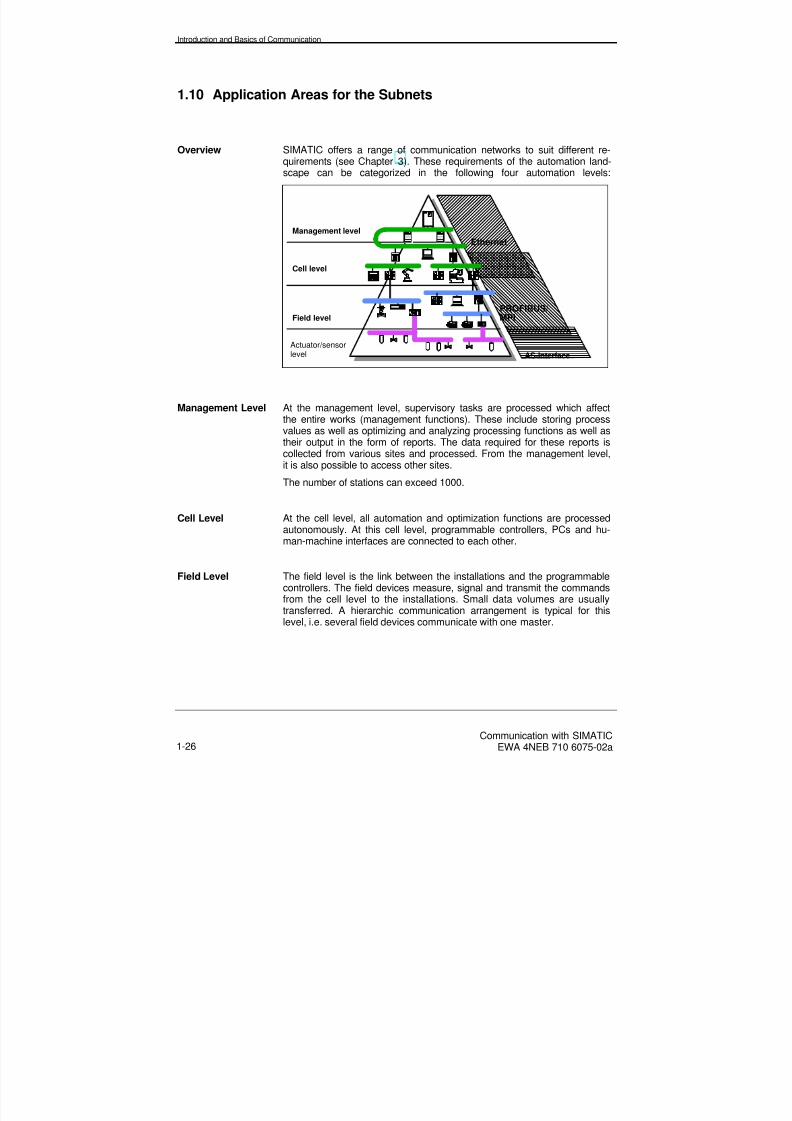
Overview SIMATIC offers a range of communication networks to suit different re-quirements (see Chapter 3). These requirements of the automation land-scape can be categorized in the following four automation levels:
Management level
Cell level
Field level
Actuator/sensorlevel
Ethernet
PROFIBUS/MPI
AS-Interface
Management Level At the management level, supervisory tasks are processed which affectthe entire works (management functions). These include storing processvalues as well as optimizing and analyzing processing functions as well astheir output in the form of reports. The data required for these reports is
collected from various sites and processed. From the management level,it is also possible to access other sites.
The number of stations can exceed 1000.
Cell Level At the cell level, all automation and optimization functions are processedautonomously. At this cell level, programmable controllers, PCs and hu-man-machine interfaces are connected to each other.
Field Level The field level is the link between the installations and the programmablecontrollers. The field devices measure, signal and transmit the commandsfrom the cell level to the installations. Small data volumes are usuallytransferred. A hierarchic communication arrangement is typical for thislevel, i.e. several field devices communicate with one master.

8/20/2019 Communication With Simatic Net
http://slidepdf.com/reader/full/communication-with-simatic-net 39/200
Introduction and Basics of Communication
Communication with SIMATICEWA 4NEB 710 6075-02a 1-27
Actuator/SensorLevel
At this level, a master communicates with the actuators and sensors thatare connected to a subnet. Its characteristic feature is a fast response timefor a small number of data bits.

8/20/2019 Communication With Simatic Net
http://slidepdf.com/reader/full/communication-with-simatic-net 40/200

8/20/2019 Communication With Simatic Net
http://slidepdf.com/reader/full/communication-with-simatic-net 41/200
Communication Services
Communication with SIMATICEWA 4NEB 710 6075-02a 2-1
2 Communication Services
Overview In this Chapter, you will find out the types of communication services thatare available and how they can be categorized in terms of performance.You will become familiar with the software interfaces for communicationservices that exist within SIMATIC.
Chapter Overview In Section You will find On page
2.1 Introduction 2-2
2.2 S7 Functions 2-4
2.3 ISO Transport Services 2-6
2.4 ISO-on-TCP Services 2-7
2.5 PROFIBUS-FDL Services 2-8
2.6 PROFIBUS-FMS Services 2-9
2.7 PROFIBUS-DP Services 2-10
2.8 Global Data Communication (GD) 2-11
2.9 AS-i Services 2-12

8/20/2019 Communication With Simatic Net
http://slidepdf.com/reader/full/communication-with-simatic-net 42/200
Communication Services
Communication with SIMATICEWA 4NEB 710 6075-02a2-2
2.1 Introduction
Definition A SIMATIC S7 communication service describes communication func-tions using defined performance features, such as data to be transferred,devices to be controlled, devices to be monitored and programs to load.The SIMATIC S7 communication services (simply referred to as servicesfrom now on) are offered via software interfaces in the data terminal (e.g.SIMATIC S7 system functions). A software interface does not necessarilyoffer all the communication functions of a service. Such a service can beprovided in the respective data terminal (e.g. PLC, PC) with differentsoftware interfaces.
Services andSubnets
Communication in SIMATIC S7 is based on various subnets on whichvarious services are provided. The following table shows the relationship
between services and subnets.
Services S7 communication functions(S7 functions)
ISO transportISO-on-TCP
FDL (SDA)FMSDP GD
Sub-nets
IndustrialEthernet
PROFIBUS MPI
A summary of the communication services that are used in SIMATIC isgiven below. For information on subnets, see Chapter 3.
S7 Functions The S7 functions offer services for communication between S7/M7 CPUs,SIMATIC OPs/OSes and PCs. The S7 functions are already integratedinto every SIMATIC S7/M7 system. The S7 functions correspond to aservice of the ISO application layer, so they are independent of the subnetand can be used in all subnets (MPI, PROFIBUS, Industrial Ethernet).
ISO Transport These functions support error-free transmission of medium data volumes(up to 240 bytes) via open communication on Layer 4 (the transport layerof the ISO reference model) with Industrial Ethernet between SIMATIC S7and SIMATIC S5.

8/20/2019 Communication With Simatic Net
http://slidepdf.com/reader/full/communication-with-simatic-net 43/200
Communication Services
Communication with SIMATICEWA 4NEB 710 6075-02a 2-3
ISO-on-TCP These functions support error-free transmission of medium data volumes(up to 240 bytes) via open communication with TCP/IP protocol on Layer 4in accordance with the ISO reference model with Industrial Ethernet be-
tween SIMATIC S7 and PCs or non-Siemens systems via TCP/IP net-works.
The ISO-on-TCP service requires the extended RFC1006 standard.
FDL (SDA) These functions support the error-free transmission of data from SIMATICS7 to SIMATIC S5.
They are optimized for the transmission of medium data volumes (up to240 bytes) via open communication on Layer 2 of the ISO referencemodel, fieldbus data link (FDL) with PROFIBUS.
FMS PROFIBUS FMS (fieldbus message specification) offers services for thetransmission of structured data (FMS variables).
The FMS service can be placed in Layer 7 of the ISO reference model. Itcomplies with the European standard EN 50170 Vol. 2 PROFIBUS andtherefore facilitates open communication between stations on PROFIBUS.
DP PROFIBUS-DP services facilitate transparent communication with distrib-uted I/O. From the control program, distributed I/O is addressed as if itwas central I/O.
This service complies with the European standard EN 50170 Vol. 2PROFIBUS master/slave and therefore facilitates open communication to
distributed I/O and field devices.
GD Global data communication is a simple communication service that isintegrated into the operating system of the S7-300/400 CPUs.
GD communication facilitates cyclic data transfer between CPUs via theMPI interface. Cyclic data transfer takes place with the normal processimage.
AS-Interface These services are provided for cyclic data transmission between a pro-grammable controller, and actuators and sensors at a lower system level.

8/20/2019 Communication With Simatic Net
http://slidepdf.com/reader/full/communication-with-simatic-net 44/200
Communication Services
Communication with SIMATICEWA 4NEB 710 6075-02a2-4
2.2 S7 Functions
Overview The S7 functions offer services for communication between S7/M7 CPUs,SIMATIC OPs/OSes and PCs. The S7 functions are already integratedinto every SIMATIC S7/M7 system. The S7 functions correspond to aservice of the Application Layer (Layer 7 of the ISO reference model), sothey are independent of the subnet and can be used in all subnets (MPI,PROFIBUS, Industrial Ethernet).
Features The S7 functions comprise the following:
• Complete functions for programming SIMATIC programmable con-trollers with STEP 7 (e.g. downloading the hardware configuration,loading STEP 7 programs, online operator control of the SIMATICstations and program testing and diagnostics).
• Writing and reading variables as well as automatic transmission ofdata to the operator control and visualization stations (OPs andOSes) without the need for additional communication functions inthe user program of the communication partner.
• Error-free transfer of an area or subarea of data blocks (up to 64Kbytes), a bit memory area or the process image between SIMATICS7/M7-400 stations. This means that data transfer is only completedwhen the receive function in the communication partner has loadedthe data (BSEND/BRCV).
• High-speed data transfer without checking, independent of the timetaken to process the communication function by the communication
partner (e.g. operating and status signals). This means that the datacan be overwritten with more up-to-date data at the communicationpartner (USEND/URCV). This is only possible betweenSIMATIC S7/M7-400 stations.
• Program controlled reading and writing of variables without the needfor additional communication functions in the user program of thecommunication partner (PUT/GET).
• Control functions in order to set the CPU of the communication part-ner into the stop state, or to trigger a complete restart or warm re-start.
• Monitoring functions that output the current operating status of theCPU of the communication partner.
The software interfaces (see Chapter 4) to the user program constitute thecommunication SFCs/SFBs that are integral to the operating system. Thedata volume lies between 76 and 460 bytes (in the case of BSEND/BRCVup to 64 Kbytes).

8/20/2019 Communication With Simatic Net
http://slidepdf.com/reader/full/communication-with-simatic-net 45/200
Communication Services
Communication with SIMATICEWA 4NEB 710 6075-02a 2-5
TransmissionReliability
A high degree of data security is achieved due to automatic repetition ofincomplete or incorrect telegrams on MPI/PROFIBUS and Industrial Eth-ernet (Layer 2 of the ISO reference model).
Transmission of the data is acknowledged by the communication partneron Layer 7 of the ISO reference model. This is indicated in the appropriateblock.
Integration inSTEP 7
The SIMATIC S7 family, together with the S7 functions offers communica-tion functions via configured and non-configured S7 links. The configuredlinks are configured using STEP 7 and are implicitly established when thestation starts up. The non-configured links are explicitly established whenthe associated communication function is called.
Assignment to
Software Interface
In SIMATIC S7-300/400 systems, the S7 functions are provided by thecommunication SFCs for non-configured links and the communicationSFBs for configured links.
In SIMATIC M7-300/400 systems, the functional scope of the S7 functionsis provided by M7 API.
On the PC, a subset of the S7 functions is provided via the SAPI-S7 inter-face.

8/20/2019 Communication With Simatic Net
http://slidepdf.com/reader/full/communication-with-simatic-net 46/200
Communication Services
Communication with SIMATICEWA 4NEB 710 6075-02a2-6
2.3 ISO Transport Services
Overview ISO transport provides services for transmitting data via links. The link isautomatically monitored by the ISO transport service.
The ISO transport service (ISO 8073 Class 4) corresponds to Level 4 ofthe ISO reference model.
Features Large quantities of data can be transmitted using the ISO transport servicedue to "data blocking", i.e. useful data can be segmented in several datatelegrams.
The ISO transport service facilitates communication to any communica-tion partner (e.g. SIMATIC S5 or PC) that supports sending and receivingdata in accordance with ISO transport.
Data is only transferred on Industrial Ethernet with the ISO transport serv-ice.
TransmissionReliability
A high degree of data security is achieved due to automatic repetition inthe case of ISO transport and additional block checking mechanisms(CRC check on Layer 2).
Receipt of data is acknowledged by the ISO transport service of the com-munication partner. This is indicated in the appropriate block.
Integration in
STEP 7
With the ISO transport services, the SIMATIC S7 family offers communi-
cation functions for sending and receiving data via static links. The asso-ciated ISO transport links are configured using STEP 7. They are estab-lished when the station starts up.
The STEP 7 "NCM S7 for Industrial Ethernet" option package supple-ments the STEP 7 link configuration with the "ISO transport" link type.
Assignment toSoftware Interface
In SIMATIC S7, the ISO transport services are used for communicationwith the blocks AG_SEND and AG_RECV via the Industrial Ethernet sub-net (see Chapter 4).
On the PC, the ISO transport services are provided in the form of C func-tions.
8/20/2019 Communication With Simatic Net
http://slidepdf.com/reader/full/communication-with-simatic-net 47/200
Communication Services
Communication with SIMATICEWA 4NEB 710 6075-02a 2-7
2.4 ISO-on-TCP Services
Overview The ISO-on-TCP service corresponds to the standard TCP/IP(Transmission Control Protocol/Internet Protocol) with the extendedRFC 1006 in accordance with Layer 4 of the ISO reference model.
RFC 1006 is required because TCP provides data stream communicationwithout blocking the data into messages.
This behavior is rectified in the case of the ISO protocol of Layer 4 with anend of message code (EOM). The EOM allows messages (data blocks) tobe transmitted. TCP/IP does not recognize this. Additive protocols have toused for the purposes of sending messages. RFC 1006 describes how theservices of ISO layer 4 can be mapped onto TCP. RFC 1006 is an officialstandard and is used by many manufacturers.
Features The ISO-on-TCP service facilitates communication to any communicationpartner (e.g. PC or non-Siemens system) that supports sending and re-ceiving data in accordance with ISO-on-TCP.
With the ISO-on-TCP service, data is only transferred on Industrial Ether-net.
TransmissionReliability
A high degree of data security is achieved due to automatic repetition andadditional block checking mechanisms (CRC check on Layer 2).
Receipt of data is acknowledged by the communication partner. This isindicated in the appropriate block.
Integration inSTEP 7
With the ISO-on-TCP services, the SIMATIC S7 offers communicationfunctions for sending and receiving data via static links. The associatedISO-on-TCP links are configured using STEP 7. They are established im-plicitly when the station starts up.
The STEP 7 "NCM S7 for Industrial Ethernet" option package supple-ments the STEP 7 link configuration with the "ISO-on-TCP" link type.
Assignment toSoftware Interface
In SIMATIC S7, the ISO-on-TCP services are used for communicationwith the blocks AG_SEND and AG_RECV via the Industrial Ethernet sub-net (see Chapter 4).
On the PC, the ISO-on-TCP services are provided in the form of C func-tions.

8/20/2019 Communication With Simatic Net
http://slidepdf.com/reader/full/communication-with-simatic-net 48/200
Communication Services
Communication with SIMATICEWA 4NEB 710 6075-02a2-8
2.5 PROFIBUS-FDL Services
Overview FDL (fieldbus data link) offers services for the transmission of data on thePROFIBUS subnet.
The FDL service of SIMATIC S7 supports the SDA function (send datawith acknowledgement).
The FDL service can be placed in Layer 2 of the ISO reference model.
PROFIBUS-FDL complies with the European standard EN 50 170 Vol. 2PROFIBUS.
Features Receipt of data is acknowledged by the FDL service of the communicationpartner.
The FDL service facilitates communication to any communication partner(e.g. SIMATIC S5 or PC) that supports sending and receiving data in ac-cordance with the SDA function.
TransmissionReliability
A high degree of data security is achieved due to automatic repetition andadditional checking mechanisms (parity bit per character and check sumon Layer 2).
Integration inSTEP 7
With the FDL service, the SIMATIC S7 offers, communication functionsfor sending and receiving data via static links. The associated FDL linksare configured using STEP 7. They are established implicitly when the
PROFIBUS-CP for SIMATIC S7 starts up.The STEP 7 "NCM S7 for PROFIBUS" option package supplements theSTEP 7 link configuration with the link type "FDL link".
Assignment toSoftware Interface
In SIMATIC S7, the FDL services are used for communication with theblocks AG_SEND and AG_RECV via the PROFIBUS subnet (see Chapter4).
On the PC, the FDL services are provided in the form of C functions.
8/20/2019 Communication With Simatic Net
http://slidepdf.com/reader/full/communication-with-simatic-net 49/200
Communication Services
Communication with SIMATICEWA 4NEB 710 6075-02a 2-9
2.6 PROFIBUS-FMS Services
Overview PROFIBUS-FMS (fieldbus message specification) offers services for thetransmission of structured data (FMS variables).
The FMS service can be placed in Layer 7 of the ISO reference model. Itcomplies with the European standard EN 50170 Vol. 2 PROFIBUS andtherefore facilitates open communication with field devices.
Features Services for reading and writing FMS variables via FMS links are avail-able.
Receipt of data is confirmed by the partner with an application acknow-ledgement, i.e. the application running on the distant communicationpartner has received the data correctly.
Data is only transferred with the FMS service on the PROFIBUS subnet.
TransmissionReliability
A high degree of data security is achieved due to automatic repetition andadditional checking mechanisms (parity bit per character and check sumon Layer 2).
Integration inSTEP 7
With the FMS service, the SIMATIC S7 offers communication functions forsending and receiving data via static links. The associated FMS links areconfigured using STEP 7. They are established implicitly when the stationfor SIMATIC S7 starts up.
The STEP 7 "NCM S7 for PROFIBUS" option package supplements theSTEP 7 link configuration with the link type "FMS link".
Assignment toSoftware Interface
In SIMATIC S7, the FMS services are used for communication with thecommunication FBs for FMS via the PROFIBUS subnet (see Chapter 4).
On the PC, the FMS services are provided in the form of C functions.

8/20/2019 Communication With Simatic Net
http://slidepdf.com/reader/full/communication-with-simatic-net 50/200
Communication Services
Communication with SIMATICEWA 4NEB 710 6075-02a2-10
2.7 PROFIBUS-DP Services
Overview PROFIBUS-DP services facilitate direct communication with distributedI/O. From the control program, distributed I/O is addressed as if it werecentral I/O.
PROFIBUS-DP services comply with the European standard EN 50170Vol. 2, PROFIBUS. Any standard slave can be connected.
Features The "distributed I/O" expands the central I/O with I/O modules that areconnected to a central controller via a parallel bus (via an IM) or a serialbus (interface on CPU, IM or CP). The serial bus is PROFIBUS-DP whichcovers open communication up to Layer 7.
The PROFIBUS-DP interface is either integrated on the S7/M7 CPUs or
separate interfaces are used (IMs, CPs).The I/O that is located, for example, in an expansion unit (ET 200 station)connected to PROFIBUS as a DP slave, is addressed in the same manneras any other I/O in the central controller or in an expansion unit. Thismeans that the I/O modules can be directly addressed using instructions orthey are accessed via process image transfer.
TransmissionReliability
A high degree of data security is achieved due to automatic repetition andadditional checking mechanisms (parity bit per character and check sumon Layer 2).
Integration inSTEP 7
Distributed I/O is configured using the hardware configuration functions ofSTEP 7.
This also applies to the system integration of the ET 200 stations.
Non-Siemens slaves can also be integrated into the hardware configura-tion system.

8/20/2019 Communication With Simatic Net
http://slidepdf.com/reader/full/communication-with-simatic-net 51/200
Communication Services
Communication with SIMATICEWA 4NEB 710 6075-02a 2-11
2.8 Global Data Communication (GD)
Overview Global data communication is a simple communication service that isintegral to the operating system of the S7-300/400 CPUs.
Features GD communication facilitates the cyclic exchange of global data, such asinputs, outputs, bit memories and areas in data blocks, between CPUs viathe MPI interface (without using blocks). Cyclic data transfer takes placewith the normal transfer of the process image.
The response time is dependent on the cycle of the user program and itsvalue is a fraction of this cycle time (GD reduction factor).
Transmission
Reliability
This technique is a broadcast technique; therefore, there is no guaranteefor data security.
Integration inSTEP 7
Global data communication is configured with STEP 7 via a global datatable. All S7-300/400 CPUs must be located in the same STEP 7 project.

8/20/2019 Communication With Simatic Net
http://slidepdf.com/reader/full/communication-with-simatic-net 52/200
Communication Services
Communication with SIMATICEWA 4NEB 710 6075-02a2-12
2.9 AS-i Services
Overview AS-i services facilitate direct communication with decentralized actuatorsand sensors. From the control program, they are addressed as if they weredistributed I/O.
The AS-i specification has been submitted in the form of a prototypestandard to the IEC and EN.
Sensors and actuators that comply with this specification can be con-nected.
Features The sensors and actuators are addressed in the central controller or ex-pansion unit in the same manner as any other I/O. This means that thesensors and actuators can be directly addressed with instructions or they
can be accessed via process image transfer.• Power is supplied and data is transferred on the same cable.
• For each AS-i slave station, 4 sensors and actuators can be con-nected.
• Up to 4 input bits and 4 output bits are available per slave station.
• Transmission takes place at a fixed cycle time of up to 5 ms.
• The response time is <= 5 ms.
The AS-i interface is available as a separate interface (CP) forSIMATIC S7-200/300 and M7 300.
TransmissionReliability
A high degree of data security is achieved due to automatic repetition andadditional checking mechanisms (parity bit and a special signal shape).
Integration inSTEP 7
As far as configuration is concerned, the CP is simply integrated duringhardware configuration.
8/20/2019 Communication With Simatic Net
http://slidepdf.com/reader/full/communication-with-simatic-net 53/200
Communication Networks
Communication with SIMATICEWA 4NEB 710 6075-02a 3-1
3 Communication Networks
Overview In this Chapter, you will become familiar with the communication networksthat are available for SIMATIC. You will learn which protocols are realizedin which network and which SIMATIC products are offered for thesecommunication networks. On the basis of this information, you will beable to select your own communication network.
Chapter Overview In Section You will find On page
3.1 Overview 3-2
3.2 Multipoint Interface (MPI) 3-5
3.3 PROFIBUS 3-7
3.4 Industrial Ethernet 3-12
3.5 Point-to-Point Link 3-14
3.6 AS-Interface 3-16

8/20/2019 Communication With Simatic Net
http://slidepdf.com/reader/full/communication-with-simatic-net 54/200
Communication Networks
Communication with SIMATICEWA 4NEB 710 6075-02a3-2
3.1 Overview
Subnets inSIMATIC SIMATIC offers the following subnets which meet the requirements of thedifferent automation system levels (management, cell, field and actua-
tor/sensor level):
MPI The MPI subnet meets the requirements of the field level and cell levelwith low coverage. MPI is a multipoint interface in SIMATIC S7/M7 and C7systems. It is designed as a programming device interface and is intendedfor networking a small number of CPUs for the purpose of exchangingsmall volumes of data.
PROFIBUS PROFIBUS is the network for the cell and field level in the open, multi-
vendor SIMATIC communication system.Two versions of PROFIBUS are offered:
• PROFIBUS DP, the fieldbus for high-speed, cyclic transfer of smallvolumes of data
• PROFIBUS, in the cell, for the high-speed exchange of medium-sized quantities of data with communication partners that have equalrights
Industrial Ethernet Industrial Ethernet is the network for the management and cell level in theopen, multi-vendor SIMATIC communication system. Industrial Ethernet issuitable for the high-speed exchange of large quantities of data and facili-tates communication between one site and another via gateways.
Point-to-PointLink
A point-to-point link is not technically a subnet. In SIMATIC, this link isimplemented via point-to-point communication processors (CP), wherebytwo stations are linked together.
AS-Interface The AS-Interface or actuator/sensor interface is a subnet system for thelowest process level in automation systems. It is specially designed for theinterconnection of binary sensors and actuators. The data volume is lim-ited to 4 bits per slave station.
8/20/2019 Communication With Simatic Net
http://slidepdf.com/reader/full/communication-with-simatic-net 55/200
Communication Networks
Communication with SIMATICEWA 4NEB 710 6075-02a 3-3
Access Technique The access technique specifies how and when a station can send its dataon the subnet. In the event of simultaneous requests to send from differentstations, it controls the access authorization. The following types of access
techniques exist:• CSMA/CD (carrier sense multiple access / collision detection)
• Token passing
• Master/slave
The access techniques are described in detail in the sections describingthe relevant subnets.
Max. Length ofNetwork
This is the greatest distance between two stations of a subnet. A subnetcan comprise one or more segments (bus segments). Bus segments canbe connected via segment couplers such as repeaters or bridges.
Transfer Medium The transfer medium is the bus cable via which data is transferred.A distinction is usually made between copper and fiber-optic cables.
• Copper: 2-core cable, coaxial cable, twisted pair
• Fiber-optic: Glass or plastic fiber-optic cables

8/20/2019 Communication With Simatic Net
http://slidepdf.com/reader/full/communication-with-simatic-net 56/200
Communication Networks
Communication with SIMATICEWA 4NEB 710 6075-02a3-4
Technical Data The following table provides an overview of the subnets.
Features MPI PROFIBUS IndustrialEthernet AS-Interface
Standards SIEMENS pro-cedure
PROFIBUS toEN 50170Volume 2
Ethernet toIEEE 802.3
AS-ispecification toIEC TG 17B
Access technique Token passing Token passingwith subordinatemaster/slave
CSMA/CD Master/slave
Transmission rate 187.5 Kbit/s 9.6 Kbit/s -12 Mbit/s
10 Mbit/s 167 Kbit/s
Transfer medium Copper:Shielded 2-core
cable
Fiber-optic:Glass or plasticfiber-optic cable
Copper:Shielded 2-core
cable
Fiber-optic:Glass or plasticfiber-optic cable
Copper:Double-shielded
coaxial cable orIndustrialTwisted Pair
Fiber-optic:Glass fiber-opticcables
Copper:Unshielded
2-core cable
Max. no. ofstations
32 127 > 1000 32
Max. length ofnetwork
50 m(expandable us-ing RS485 re-
peaters or opti-cal link modules)
Copper:Approx. 10 km 1)
Fiber-optic:over 100 km 2)
Copper:1.5 km
Fiber-optic:4.5 km
Cable length max.300 m
Topology Line, tree,
ring, star
Line, tree,
ring, star
Line, tree,
ring, star
Line, tree
Services S7 functions, GD S7 functions,FDL, FMS, DP
S7 functions,ISO transport,ISO-on-TCP
AS-i functions
Automation systemlevel
Cell and fieldlevel
Cell and fieldlevel
Managementand cell level
Actuator/sensorlevel
Hamming distance 4 4 2 -
1)
Depends on transmission rate2)Depends on OLM type used
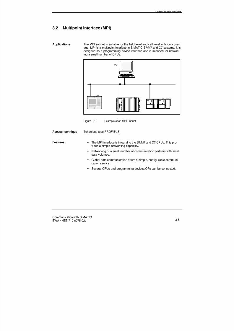
8/20/2019 Communication With Simatic Net
http://slidepdf.com/reader/full/communication-with-simatic-net 57/200
Communication Networks
Communication with SIMATICEWA 4NEB 710 6075-02a 3-5
3.2 Multipoint Interface (MPI)
Applications The MPI subnet is suitable for the field level and cell level with low cover-age. MPI is a multipoint interface in SIMATIC S7/M7 and C7 systems. It isdesigned as a programming device interface and is intended for network-ing a small number of CPUs.
MPI
S7 - 300S7 - 400
PG
OP
Figure 3-1: Example of an MPI Subnet
Access technique Token bus (see PROFIBUS)
Features • The MPI interface is integral to the S7/M7 and C7 CPUs. This pro-vides a simple networking capability.
• Networking of a small number of communication partners with smalldata volumes.
• Global data communication offers a simple, configurable communi-cation service.
• Several CPUs and programming devices/OPs can be connected.
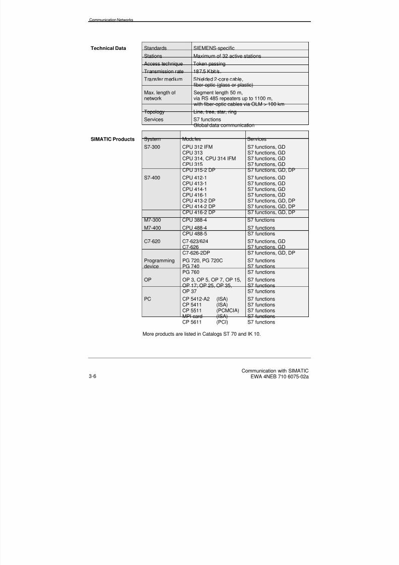
8/20/2019 Communication With Simatic Net
http://slidepdf.com/reader/full/communication-with-simatic-net 58/200
Communication Networks
Communication with SIMATICEWA 4NEB 710 6075-02a3-6
Technical Data Standards SIEMENS-specific
Stations Maximum of 32 active stations
Access technique Token passing
Transmission rate 187.5 Kbit/s.
Transfer medium Shielded 2-core cable,fiber-optic (glass or plastic)
Max. length ofnetwork
Segment length 50 m,via RS 485 repeaters up to 1100 m,with fiber-optic cables via OLM > 100 km
Topology Line, tree, star, ring
Services S7 functionsGlobal data communication
SIMATIC Products System Modules Services
S7-300 CPU 312 IFM
CPU 313CPU 314, CPU 314 IFMCPU 315CPU 315-2 DP
S7 functions, GD
S7 functions, GDS7 functions, GDS7 functions, GDS7 functions, GD, DP
S7-400 CPU 412-1CPU 413-1CPU 414-1CPU 416-1CPU 413-2 DPCPU 414-2 DPCPU 416-2 DP
S7 functions, GDS7 functions, GDS7 functions, GDS7 functions, GDS7 functions, GD, DPS7 functions, GD, DPS7 functions, GD, DP
M7-300 CPU 388-4 S7 functions
M7-400 CPU 488-4CPU 488-5 S7 functionsS7 functions
C7-620 C7-623/624C7-626C7-626-2DP
S7 functions, GDS7 functions, GDS7 functions, GD, DP
Programmingdevice
PG 720, PG 720CPG 740PG 760
S7 functionsS7 functionsS7 functions
OP OP 3, OP 5, OP 7, OP 15,OP 17; OP 25, OP 35,OP 37
S7 functionsS7 functionsS7 functions
PC CP 5412-A2 (ISA)
CP 5411 (ISA)CP 5511 (PCMCIA)MPI card (ISA)CP 5611 (PCI)
S7 functions
S7 functionsS7 functionsS7 functionsS7 functions
More products are listed in Catalogs ST 70 and IK 10.

8/20/2019 Communication With Simatic Net
http://slidepdf.com/reader/full/communication-with-simatic-net 59/200
Communication Networks
Communication with SIMATICEWA 4NEB 710 6075-02a 3-7
3.3 PROFIBUS
Definition PROFIBUS is the network for the cell and field level in the open, multi-vendor SIMATIC communication system. PROFIBUS is physically either acopper cable network based on a shielded 2-core cable or a fiber-opticcable network.
Access technique The network access technique for PROFIBUS corresponds to the "Tokenbus" method specified by EN 50170, Volume 2 for active stations and the"Master/slave" method for passive stations.
Figure 3-2: Principle of the PROFIBUS Access Technique
The access technique is independent of the transfer medium. Figure 3-2shows the procedure used with active and passive stations. This is ex-plained briefly below:
All active stations (masters) form, in a prespecified sequence, the "logicaltoken ring" whereby each active station is aware of the other active sta-tions and their sequence in the logical ring (the sequence is independentof the topological arrangement of the active stations on the bus).
The right to access the medium (the "token") is passed from active stationto active station in accordance with the sequence specified by the logicalring.
When a station receives the token (addressed to it), it has permission tosend telegrams. The time allowed is specified by the so-called tokenholding time. Once this has elapsed, the station is only permitted to sendone more high-priority message. If the station is not waiting to send amessage, it passes the token onto the next station in the logical ring im-mediately. The corresponding token timers ("max. token holding time",etc.) are configured for all active stations.
PROFIBUS
Master/slave assignment
Token
Slave Slave SlaveSlave SlaveSlave
MasterMasterMaster

8/20/2019 Communication With Simatic Net
http://slidepdf.com/reader/full/communication-with-simatic-net 60/200
Communication Networks
Communication with SIMATICEWA 4NEB 710 6075-02a3-8
If an active station is in possession of the token and connections to pas-sive stations are configured for it (master/slave links), these passive sta-tions are queried (e.g. variables are read) or data is sent to them (e.g.setpoint values).
Passive stations never receive the token.This access technique allows stations to be added and removed underoperating conditions.
Applications forPROFIBUS
The PROFIBUS subnet for the cell and field level supports the exchangeof information between field devices and with systems at a higher systemlevel. It is used to transfer small to medium quantities of data. In SIMATICS7, a CP is always required for PROFIBUS.
PROFIBUS
S7 - 300
S5 with PROFIBUS-CPPG
OPS7 - 400 PROFIBUS-CP
PROFIBUS-CP
PROFIBUS-CP
Figure 3-3: Example of a PROFIBUS Subnet

8/20/2019 Communication With Simatic Net
http://slidepdf.com/reader/full/communication-with-simatic-net 61/200
Communication Networks
Communication with SIMATICEWA 4NEB 710 6075-02a 3-9
Applications forPROFIBUS-DP
PROFIBUS-DP offers a standardized interface for the transfer of processinput and process output data between SIMATIC S7 stations and fielddevices (DP slaves). PROFIBUS-DP is characterized by high-speed, cy-
clic exchange of small quantities of data between DP masters and DPslaves.
DP master
PROFIBUS
DP masterPG/PC
e.g.
AG 95U/DPslave
DP slave
CP
Non-SiemensDP slave
S7 - 315-2 DP
S7 - 300 PROFIBUS-CP
STEP 7NCM S7 for
PROFIBUS
e.g.
ET 200 M/U/B
PROFIBUS-CP
OP
Figure 3-4: Example of a PROFIBUS-DP Subnet
Features ofPROFIBUS
• The following services can be used simultaneously on PROFIBUS
− FDL, FMS and S7 functions or
− DP, FDL and S7 functions.
• Defined bus circulation times are guaranteed by the token passingtechnique.
• PROFIBUS-DP allows data to be exchanged between master andslave stations from different manufacturers without the need forspecial adaptation of the interface.
• In SIMATIC S7/M7, PROFIBUS-DP interfaces have been integratedinto the CPUs (second interface for S7 CPUs or interface submod-ule for M7 CPUs). To the customer, this means:
− the single-master with integrated interface guarantees faster re-sponse times (1 to 2 ms for 12 Mbit/s).
− integrated interfaces are less expensive than separate interfacesand consume less space.
• Extremely fast response (1 to 5 ms) on querying DP slaves.
• PROFIBUS allows data to be exchanged between stations via FMSor FDL without the need for special adaptation of the interface.

8/20/2019 Communication With Simatic Net
http://slidepdf.com/reader/full/communication-with-simatic-net 62/200
Communication Networks
Communication with SIMATICEWA 4NEB 710 6075-02a3-10
Technical Data Standards EN 50170 Volume 2 PROFIBUS
Stations Maximum of 127 stations in the network
Access techniques - Token bus for bus allocation among active sta-tions.
- Master/slave for communication with passive sta-tions.
Transmission rate 9.6 Kbit/s to 12 Mbit/s
Transfer medium Shielded 2-core cable or fiber-optic cable
Transmission rate Length
Copper:
Per segment 9.6 to 93.75 Kbit/s 1000 m
187.5 Kbit/s 800 m
500 Kbit/s 400 m
1.5 Mbit/s 200 m
3 to 12 Mbit/s 100 m
With repeaters 9.6 to 93.75 Kbit/s 10 km
187.5 Kbit/s 8 km
500 Kbit/s 4 km
1.5 Mbit/s 2 km
3 to 12 Mbit/s 1 km
Fiber-optic:
(depending ontype of OLMused)
9.6 Kbit/s to 12 Mbit/s >100km
Topology Line, tree, star, ring
Services S7 functionsFDLFMSDP

8/20/2019 Communication With Simatic Net
http://slidepdf.com/reader/full/communication-with-simatic-net 63/200
Communication Networks
Communication with SIMATICEWA 4NEB 710 6075-02a 3-11
SIMATIC Products System Modules Services
S5 95U CPU 95U FDL, DP (M or S) *)
S5115/135/
155U
CP 5431IM 308-B/C
FMS, FDL, DP (M)DP (M or S)
S7-200 CPU 215 DP (S)
S7-300 CPU 315-2 DPCP 342-5CP 343-5
DP (M or S)S7 functions, FDL, DP (M or S)S7 functions, FDL, FMS
S7-400 CPU 413-2 DPCPU 414-2 DPCPU 416-2 DPIM 467CP 443-5 BasicCP 443-5 Extended
DP (M)DP (M)DP (M)DP (M or S), (M and S)S7 functions, FDL, FMSS7 functions, FDL, DP (M or S)
M7-300/400 IFM submodule S7 functions, DP (M or S)
C7 CPU 626-DP DPOP OP 5, OP 7, OP 15,
OP 17; OP 25, OP 35,OP 37
S7 functionsS7 functionsS7 functions
PC/ program-mingdevice
CP 5412 A2 (ISA)
CP 5411 (ISA)CP 5511 (PCMCIA)CP 5611 (PCI)
S7 functions, FDL, FMS, DP(M) *)
S7 functions, FDL, DP (M) *)
S7 functions, FDL, DP (M) *)
S7 functions
*) Depends on configuration ordered
M = Master
S = Slave
More products are listed in Catalogs ST 50, ST 70 and IK 10

8/20/2019 Communication With Simatic Net
http://slidepdf.com/reader/full/communication-with-simatic-net 64/200
Communication Networks
Communication with SIMATICEWA 4NEB 710 6075-02a3-12
3.4 Industrial Ethernet
Applications Industrial Ethernet is a subnet for the management level and the cell levelthat supports communication between computers and programmable con-trollers. It is used for the transmission of large quantities of data and canbe used for transmission over large distances. Physically, Ethernet is acopper cable network based on a shielded coaxial cable, a twisted-paircable, or a fiber-optic network.
Industrial Ethernet
PC with Ethernet-CP
HMI / control
STEP 7NCM S7
S7 - 300 with Ethernet-CP
PG with Ethernet-CP
S7 - 400 with Ethernet-CP
M7 with Ethernet-CP S5 with Ethernet-CP
Figure 3-5: Example of an Industrial Ethernet Subnet
Access technique The CSMA/CD access technique is used. Before transmission, each sta-tion checks whether other stations are currently transmitting. If no otherstation is transmitting, it can start sending immediately. If a collision oc-curs due to two stations starting to transmit simultaneously, they both stoptransmitting and repeat the procedure once a random waiting time haselapsed.
Features • In the case of Industrial Ethernet, the ISO and TCP/IP protocols areused.
• Due to the access technique used, all stations on Industrial Ethernethave equal rights.
• A large variety of non-Siemens systems can be accessed via ISOtransport or ISO-on-TCP.

8/20/2019 Communication With Simatic Net
http://slidepdf.com/reader/full/communication-with-simatic-net 65/200
Communication Networks
Communication with SIMATICEWA 4NEB 710 6075-02a 3-13
Technical Data Standards IEEE 802.3
Stations More than 1000
Access technique CSMA/CD (carrier sense multipleaccess/collision detection)
Transmission rate 10 Mbit/sTransfer medium Copper: 2-core, shielded coaxial cable
Industrial Twisted Pair
Fiber-optic: Fiber-optic cable
Max. length ofnetwork
Copper: 1.5 km
Fiber-optic: 4.5 km
Topology Line, tree, star, ring
Services S7 functionsISO transportISO-on-TCP
SIMATIC Products System Modules Services
S5 115/135/155U CP 1430CP 1430 TCP
ISO transportISO-on-TCP
S7-300 CP 343-1CP 343-1 TCP
S7 functions, ISO transportS7 functions, ISO-on-TCP
S7-400 CP 443-1CP 443-1 TCP
S7 functions, ISO transportS7 functions, ISO-on-TCP
PC / programmingdevice
CP 1413(ISA)CP 1411
(ISA)CP 1511(PCMCIA)
S7 functions, ISO transport,ISO-on-TCPS7 functions, ISO transport,
ISO-on-TCPS7 functions, ISO transport,ISO-on-TCP
Further products are listed in Catalogs ST 50, ST 70 and IK 10

8/20/2019 Communication With Simatic Net
http://slidepdf.com/reader/full/communication-with-simatic-net 66/200
Communication Networks
Communication with SIMATICEWA 4NEB 710 6075-02a3-14
3.5 Point-to-Point Link
Applications A point-to-point link allows data to be exchanged via a serial link. Thepoint-to-point link can be used between your system and other program-mable controllers, computers or non-Siemens systems with communica-tion capability.
A point-to-point link is not classified as a subnet.
PCS7 - 400 with point-to-point CP
Figure 3-6: Example of a Point-to-Point Link
Features • Adaptation to the protocol of the communication partner with the aidof standard procedures or loadable special drivers.
• A customized procedure can be defined using ASCII characters.
Technical Data Stations 2Transfer medium Serial interface-specific cable
Physical interfaces RS 232C (V24)20 mA (TTY)RS 422/485
Transmission rates From 300 bit/s tomax. 76.8 Kbit/s with RS 232C and RS 422/485max. 19.2 Kbit/s with 20 mA
Max. length ofnetwork
10 m with RS 232C1000 m with 20 mA and 9.6 Kbit/s1200 m with RS 422/485 and 19,200 Kbit/s
Protocol drivers ASCII driver
3964 (R)RK 512Printer driverLoadable special drivers

8/20/2019 Communication With Simatic Net
http://slidepdf.com/reader/full/communication-with-simatic-net 67/200
Communication Networks
Communication with SIMATICEWA 4NEB 710 6075-02a 3-15
SIMATIC Products System Modules Procedures / Drivers
S5 95/100U CP 521 3964 (R), ASCII
S5 115/135/155U CP 523CP 524/525
CP 544CP 544 B
3964 (R), ASCII3964 (R), RK 512, ASCII,
loadable special drivers3964 (R), RK 512, ASCII3964 (R), RK 512, ASCII,loadable special drivers
S7-300 CP 340-RS 232CCP 340-20mACP 340-RS 422/485
3964 (R), ASCII3964 (R), ASCII3964 (R), ASCII
S7-400 CP 441-1CP 441-2
3964 (R), RK512, ASCII3964 (R), RK512, ASCII, load-able special drivers
M7-300/400 IFM submodule 3964 (R), RK512, ASCII, load-able special drivers

8/20/2019 Communication With Simatic Net
http://slidepdf.com/reader/full/communication-with-simatic-net 68/200
Communication Networks
Communication with SIMATICEWA 4NEB 710 6075-02a3-16
3.6 AS-Interface
Applications The AS-Interface or actuator/sensor interface (abbreviated: AS-i) is asubnet for the lowest process level in automation systems. The simplesttypes of binary actuators and sensors are linked to an automation systemstation via the AS-i bus.
SIMATIC S7 300
AS-i module AS-i module
AS-InterfacedistributorActuator / sensor
AS-i Bus
AS-Interfacepower supply CP 342-2
Figure 3-7: Example of an AS-i Subnet
Access technique The AS-Interface is a so-called "Single-master system", i.e. only onemaster exists in each AS-i subnet that controls data transfer. It calls allslaves in sequence and reads or writes the data. Master/slave access withcyclic polling guarantees a defined response time.
Features • AS-Interface is optimized for interfacing to binary actuators and sen-sors. The AS-i bus is not simply dedicated to the transfer of databetween sensors/actuators and the master, it also supplies power tothe sensors.
• AS-i modules are available for 1 to 8 bits (channels) and are de-signed to the IP65 degree of protection. They are suitable for directinstallation on the machine or equipment.
• No configuration is required before start-up.Slaves can be replaced without the need for configuration.
• The AS-i master conducts cyclic data transfer with up to 31 stationsin less than 5 ms.
• Numerous devices (actuators/sensors) can be connected as a resultof manufacturer-independent standardization.
• A power supply unit is required for supplying power via the bus.
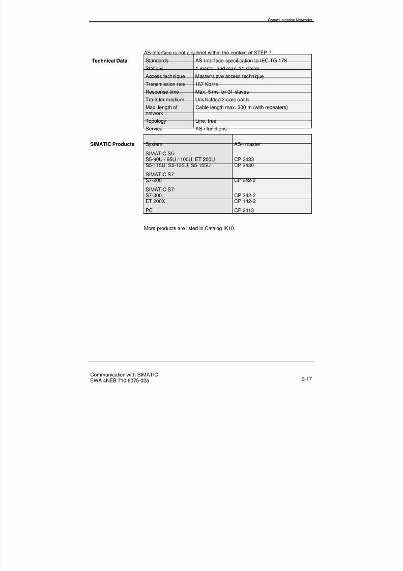
8/20/2019 Communication With Simatic Net
http://slidepdf.com/reader/full/communication-with-simatic-net 69/200
Communication Networks
Communication with SIMATICEWA 4NEB 710 6075-02a 3-17
AS-Interface is not a subnet within the context of STEP 7.
Technical Data Standards AS-Interface specification to IEC TG 178
Stations 1 master and max. 31 slaves
Access technique Master/slave access techniqueTransmission rate 167 Kbit/s
Response time Max. 5 ms for 31 slaves
Transfer medium Unshielded 2-core cable
Max. length ofnetwork
Cable length max. 300 m (with repeaters)
Topology Line, tree
Service AS-i functions
SIMATIC Products System AS-i master
SIMATIC S5:S5-90U / 95U / 100U, ET 200US5-115U, S5-135U, S5-155U
CP 2433CP 2430
SIMATIC S7:S7-200 CP 242-2
SIMATIC S7:S7-300,ET 200X
CP 342-2CP 142-2
PC CP 2413
More products are listed in Catalog IK10.

8/20/2019 Communication With Simatic Net
http://slidepdf.com/reader/full/communication-with-simatic-net 70/200

8/20/2019 Communication With Simatic Net
http://slidepdf.com/reader/full/communication-with-simatic-net 71/200
Communication Functions for S7-300/400
Communication with SIMATICEWA 4NEB 710 6075-02a 4-1
4 Communication Functions for S7-300/400
Description In this Chapter, you will find out about the communication functions ofS7-300/400.
In Section You will find On page
4.1 Introduction 4-2
4.2 Communication SFCs for Non-Configured S7Links
4-3
4.3 Communication SFBs for Configured S7 Links 4-8
4.4 SEND/RECEIVE Interface 4-13
4.5 FMS Interface 4-15
4.6 Communication via Point-to-Point Links 4-18

8/20/2019 Communication With Simatic Net
http://slidepdf.com/reader/full/communication-with-simatic-net 72/200
Communication Functions for S7-300/400
Communication with SIMATICEWA 4NEB 710 6075-02a4-2
4.1 Introduction
Definition Program-controlled communication allows you to explicitly define thefunctions required, i.e. the point in time, the quantity of data and thetransmission technique, by calling a communication function in a userprogram.
For the purposes of transferring data, appropriate communication func-tions are available on the S7-300/400 (SFCs, SFBs, loadable FC/FBs).
The assignment of communication services to software interfaces inSIMATIC is shown in the following table together with the associatedsoftware packages.
Program-Controlled Communication
Services Software Interfaces Software Packages
S7 functions Communication SFCs for non-configured S7 links
STEP 7 Version 3.1upwards
Communication SFBs for con-figured S7 links
STEP 7 Version 2.xupwards
M7-API for configured andnon-configured S7 links
M7-SYS Version 2.0(RMOS32)see Chapter 5(see Chapter 6)
SAPI-S7 for configured S7links (only client functions)
SAPI S7 for PCs(option package)
ISO transport Loadable FCs of theSEND/RECEIVE interfacevia ISO transport links
NCM S7 for IndustrialEthernet (option pack-age)
ISO-on-TCP Loadable FCs of theSEND/RECEIVE interfacevia ISO-on-TCP links
NCM S7 for IndustrialEthernet (option pack-age)
FDL (SDA) Loadable FCs of theSEND/RECEIVE interfacevia FDL links
NCM S7 for PROFIBUS(option package)
FMS Loadable FBs of theopen interfacevia FMS links
NCM S7 for PROFIBUS(option package)
8/20/2019 Communication With Simatic Net
http://slidepdf.com/reader/full/communication-with-simatic-net 73/200
Communication Functions for S7-300/400
Communication with SIMATICEWA 4NEB 710 6075-02a 4-3
4.2 Communication SFCs for Non-Configured S7 Links
Overview These communication SFCs can be used on all S7-300/400 CPUs andsupport the exchange of data with S7/M7-300/400 CPUs. These functionssupport the transfer of small quantities of data (max. 76 bytes) via the MPIsubnet or within an S7 station. It is not necessary to configure links.
Links When a communication SFC is called, a link to the addressed communi-cation partner is dynamically established and depending on the parame-terization is removed on completion of the data transmission. For this pur-pose, one spare link resource is required in each communication partner.
Link
Resources
If no spare resources are available on the communication partner, a new
link cannot be established (temporary resource shortage, SFC error classin RET_VAL).
The communication SFCs must not be deleted in the RUN operatingstate, otherwise any reserved resources cannot be released (only modifyprogram in the STOP state).
Blocks The communication SFCs do not require any additional user memory(e.g. due to instance data blocks).
The SFCs can be parameterized, i.e. the block parameters can be modi-fied dynamically during program execution. This function allows for ex-ample, different communication partners to be accessed via an SFC.
On the server side, no SFCs are necessary in the user program for certainfunctions because these communication functions are already processedby the operating system.
Size of Useful Data For all S7/M7/C7 CPUs, the size of useful data that can be transmitted is76 bytes maximum.
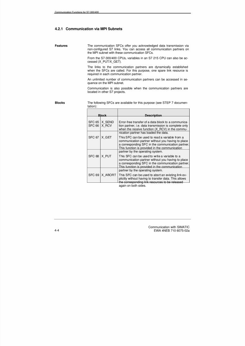
8/20/2019 Communication With Simatic Net
http://slidepdf.com/reader/full/communication-with-simatic-net 74/200
Communication Functions for S7-300/400
Communication with SIMATICEWA 4NEB 710 6075-02a4-4
4.2.1 Communication via MPI Subnets
Features The communication SFCs offer you acknowledged data transmission vianon-configured S7 links. You can access all communication partners onthe MPI subnet with these communication SFCs.
From the S7-300/400 CPUs, variables in an S7 215 CPU can also be ac-cessed (X_PUT/X_GET).
The links to the communication partners are dynamically establishedwhen the SFCs are called. For this purpose, one spare link resource isrequired in each communication partner.
An unlimited number of communication partners can be accessed in se-quence on the MPI subnet.
Communication is also possible when the communication partners arelocated in other S7 projects.
Blocks The following SFCs are available for this purpose (see STEP 7 documen-tation):
Block Description
SFC 65SFC 66
X_SENDX_RCV
Error-free transfer of a data block to a communica-tion partner, i.e. data transmission is complete onlywhen the receive function (X_RCV) in the commu-nication partner has loaded the data.
SFC 67 X_GET This SFC can be used to read a variable from a
communication partner without you having to placea corresponding SFC in the communication partner.This function is provided in the communicationpartner by the operating system.
SFC 68 X_PUT This SFC can be used to write a variable to acommunication partner without you having to placea corresponding SFC in the communication partner.This function is provided in the communicationpartner by the operating system.
SFC 69 X_ABORT This SFC can be used to abort an existing link ex-plicitly without having to transfer data. This allowsthe corresponding link resources to be released
again on both sides.

8/20/2019 Communication With Simatic Net
http://slidepdf.com/reader/full/communication-with-simatic-net 75/200
Communication Functions for S7-300/400
Communication with SIMATICEWA 4NEB 710 6075-02a 4-5
Addressing The communication partners are addressed in the case of the blockslisted above via the MPI address that is configured using STEP 7. The
communication partner can also be located in another S7 project.
Data Consistency This is the maximum data area that can be read or written as a continuousblock by the operating system (X_PUT/X_GET) in the case of S7-300/400CPUs.
An array of the data types byte, word and double-word can be transferredconsistently up to a maximum CPU-specific length as follows:
CPU 31x CPU 412 CPU 413 CPU 414 CPU 416
8 bytes 32 bytes 32 bytes 32 bytes 32 bytes
If larger quantities of useful data are transferred using X_PUT/X_GET,inconsistencies can occur.
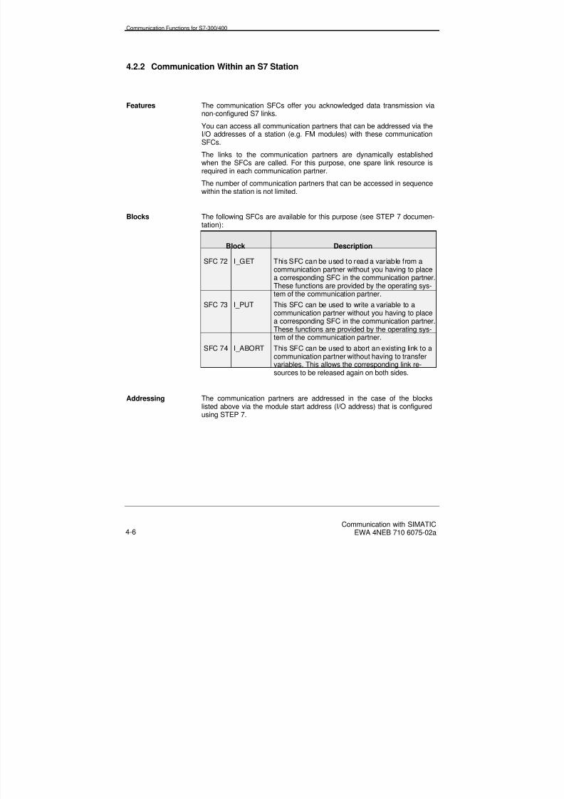
8/20/2019 Communication With Simatic Net
http://slidepdf.com/reader/full/communication-with-simatic-net 76/200
Communication Functions for S7-300/400
Communication with SIMATICEWA 4NEB 710 6075-02a4-6
4.2.2 Communication Within an S7 Station
Features The communication SFCs offer you acknowledged data transmission vianon-configured S7 links.
You can access all communication partners that can be addressed via theI/O addresses of a station (e.g. FM modules) with these communicationSFCs.
The links to the communication partners are dynamically establishedwhen the SFCs are called. For this purpose, one spare link resource isrequired in each communication partner.
The number of communication partners that can be accessed in sequencewithin the station is not limited.
Blocks The following SFCs are available for this purpose (see STEP 7 documen-tation):
Block Description
SFC 72 I_GET This SFC can be used to read a variable from acommunication partner without you having to placea corresponding SFC in the communication partner.These functions are provided by the operating sys-tem of the communication partner.
SFC 73 I_PUT This SFC can be used to write a variable to acommunication partner without you having to place
a corresponding SFC in the communication partner.These functions are provided by the operating sys-tem of the communication partner.
SFC 74 I_ABORT This SFC can be used to abort an existing link to acommunication partner without having to transfervariables. This allows the corresponding link re-sources to be released again on both sides.
Addressing The communication partners are addressed in the case of the blockslisted above via the module start address (I/O address) that is configuredusing STEP 7.

8/20/2019 Communication With Simatic Net
http://slidepdf.com/reader/full/communication-with-simatic-net 77/200
Communication Functions for S7-300/400
Communication with SIMATICEWA 4NEB 710 6075-02a 4-7
Data Consistency This is the maximum data area that can be read or written as a continuousblock by the operating system (I_PUT/I_GET) in the case of S7-300/400CPUs.
An array of the data types byte, word and double-word can be transferredconsistently up to a maximum CPU-specific length as follows:
CPU 31x CPU 412 CPU 413 CPU 414 CPU 416
8 bytes 32 bytes 32 bytes 32 bytes 32 bytes
If larger quantities of useful data are transferred using I_PUT/I_GET, in-consistencies can occur.

8/20/2019 Communication With Simatic Net
http://slidepdf.com/reader/full/communication-with-simatic-net 78/200
Communication Functions for S7-300/400
Communication with SIMATICEWA 4NEB 710 6075-02a4-8
4.3 Communication SFBs for Configured S7 Links
Overview You can use these SFBs on all S7-400 CPUs. They support the exchangeof data with S7/M7-300/400 CPUs. These functions can be used to trans-fer up to 64 Kbytes of data via the MPI, PROFIBUS and Industrial Ether-net subnets.
Features The communication SFBs offer you acknowledged data transmission viaconfigured S7 links. These links are set up using STEP 7.
The communication SFBs can only be used on CPUs of the S7-400 fam-ily. Data can only be read from or written to S7-300 CPUs (PUT/GET).
The communication functions are not limited to data transfer, additionalfunctions can be used to control and monitor the communication partner.
Communication is only possible within an S7 project. The communicationpartners must be connected to the same subnet.
Links S7 links configured using STEP 7 are required for the communicationSFBs.
These links are established on initial start of the stations and remain es-tablished permanently, even when the station switches to the STOP state.
When a station restarts (warm), the links are not established anew.
Blocks These communication SFBs are integral to the operating system of the
S7-400 CPUs. The communication SFBs require instance DBs (programmemory space) for the current parameters and the static data.
On the server side, no SFBs are required in the user program for the PUTand GET functions because these functions are already processed by theoperating system.
Subnets To be accessible, the communication partners must be connected to acommon MPI subnet, PROFIBUS subnet or Industrial Ethernet.

8/20/2019 Communication With Simatic Net
http://slidepdf.com/reader/full/communication-with-simatic-net 79/200
Communication Functions for S7-300/400
Communication with SIMATICEWA 4NEB 710 6075-02a 4-9
Size of Useful Data The maximum size of useful data that can be transferred depends on thetype of block used and the communication partner.
Block S7-400 toS7-300 (server)
S7-400 to S7-400S7-400 to M7-300/400
PUT/GET 160 bytes 1) 400 bytes 1)
USEND/URCV - 440 bytes 1)
BSEND/BRCV - 64 Kbytes
1)This is the total size of the useful data for an SFB with 1 to 4 variables.
Function Classes The communication SFBs can be categorized as follows:• Send and receive functions
• Control functions
• Monitoring functions
• Query functions

8/20/2019 Communication With Simatic Net
http://slidepdf.com/reader/full/communication-with-simatic-net 80/200
Communication Functions for S7-300/400
Communication with SIMATICEWA 4NEB 710 6075-02a4-10
Send and ReceiveFunctions
You can use these communication SFBs to transfer data between twocommunication partners.
The following SFBs (see STEP 7 documentation) are available:
Block Description
SFB 8SFB 9
USENDURCV
High-speed transfer of data without checking, inde-pendent of the time taken to process the communi-cation function (URCV) by the communication part-ner (e.g. operating and maintenance signals). Thismeans that the data can be overwritten with moreup-to-date data at the communication partner.
SFB 12SFB 13
BSENDBRCV
Error-free transfer of a data block to a communica-tion partner, i.e. data transmission is complete onlywhen the receive function (BRCV) in the communi-
cation partner has loaded the data.SFB 14 GET Program-controlled reading of variables without the
need for additional communication functions in theuser program of the communication partner.
SFB 15 PUT Program-controlled writing of variables without theneed for additional communication functions in theuser program of the communication partner.
Data Consistency In the case of S7-300/400 CPUs, this is the maximum data area that canbe read or written as a continuous block by the operating system (e.g.PUT/GET).
An array of the data types byte, word and double-word can be transferredconsistently up to a maximum CPU-specific length as follows:
CPU 31x CPU 412 CPU 413 CPU 414 CPU 416
8 bytes 32 bytes 32 bytes 32 bytes 32 bytes
If larger quantities of useful data are transferred using PUT/GET, incon-sistencies can occur.

8/20/2019 Communication With Simatic Net
http://slidepdf.com/reader/full/communication-with-simatic-net 81/200
Communication Functions for S7-300/400
Communication with SIMATICEWA 4NEB 710 6075-02a 4-11
Control Functions Using these communication SFBs, you can control the operating status ofa communication partner.
Block Description
SFB 19 START This triggers a complete restart for anS7/M7-300/400 CPU when it is in the STOP state.
SFB 20 STOP This stops an S7/M7-300/400 CPU when it is in theRUN, HALT or start-up state.
SFB 21 RESUME This triggers a warm restart for an S7-400 CPUwhen it is in the STOP state.
MonitoringFunctions
Using these communication SFBs, you can obtain information about theoperating status of a communication partner.
Block Description
SFB 22 STATUS Outputs the operating status of a communicationpartner (S7-300/400 CPU) in response to a userprogram request.
SFB 23 USTATUS This receives the operating status of an S7-400CPU on status change, provided that the appropri-ate link attribute (operating status signals for send)is set.
Query Function You can use this function to query the internal status of the local commu-nication SFB and the associated link in the program.
Block Description
SFC 62 CONTROL Queries the status of a link.
Addressing The communication partner is addressed via the local link end point (localID). The local ID is generated by STEP 7 when the link is configured. Thecommunication partners must be within an S7 project. The local ID is onlyloaded when the communication SFB is initially called and remains validuntil the next complete restart.
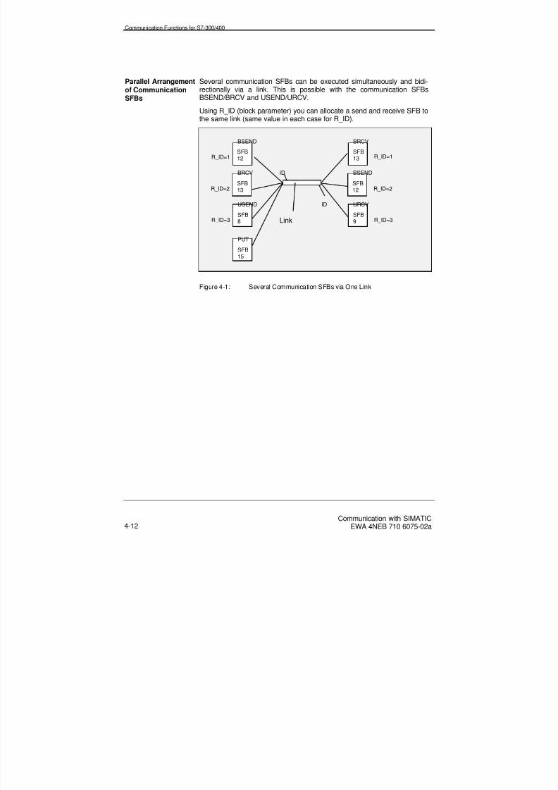
8/20/2019 Communication With Simatic Net
http://slidepdf.com/reader/full/communication-with-simatic-net 82/200
Communication Functions for S7-300/400
Communication with SIMATICEWA 4NEB 710 6075-02a4-12
Parallel Arrangementof CommunicationSFBs
Several communication SFBs can be executed simultaneously and bidi-rectionally via a link. This is possible with the communication SFBsBSEND/BRCV and USEND/URCV.
Using R_ID (block parameter) you can allocate a send and receive SFB tothe same link (same value in each case for R_ID).
Figure 4-1: Several Communication SFBs via One Link
SFB13R_ID=2
SFB12
BSEND BRCV
URCV
BSEND
R_ID=1
BRCV
USEND
SFB8
PUT
SFB15
R_ID=3
SFB12 R_ID=2
SFB13
Link
R_ID=1
ID
ID
SFB9 R_ID=3

8/20/2019 Communication With Simatic Net
http://slidepdf.com/reader/full/communication-with-simatic-net 83/200
Communication Functions for S7-300/400
Communication with SIMATICEWA 4NEB 710 6075-02a 4-13
4.4 SEND/RECEIVE Interface
Overview The principle function of the SEND/RECEIVE interface is to link theSIMATIC S7 to the SIMATIC S5, as well as to other non-S7 stations (e.g.PCs).
This interface is built up from the loadable blocks AG_SEND andAG_RECV for S7 or the handling blocks SEND and RECEIVE for S5.
These communication functions support the transfer of medium quantitiesof data (up to 240 bytes).
The SEND/RECEIVE interface permits data to be exchanged via:
• Industrial Ethernet (ISO transport, ISO-on-TCP)
• PROFIBUS (FDL)
The typical response time for a data transmission usingAG_SEND/AG_RECEIVE is 10 ms.
Features The SEND/RECEIVE interface supports simple data transfer between twocommunication partners without an acknowledgement at the user programlevel via a link configured using STEP 7:
• From SIMATIC S7 to SIMATIC S5
• From SIMATIC S7 to PC/programming device
• From SIMATIC S7 to non-Siemens systems
• From SIMATIC S7 to SIMATIC S7.
Communication between stations in different STEP 7 projects is possible.
Links Links configured using STEP 7 are required for the AG_SEND / AG_RECEIVE blocks.
These links are established when the stations start up and remain estab-lished permanently, even when the CPU switches to the STOP state.
When the CP is in the STOP state, all links are removed.

8/20/2019 Communication With Simatic Net
http://slidepdf.com/reader/full/communication-with-simatic-net 84/200
Communication Functions for S7-300/400
Communication with SIMATICEWA 4NEB 710 6075-02a4-14
Blocks For the purpose of processing the communication via links, two loadableFC blocks are available:
Block Description
FC 5 AG_SEND This sends data blocks via a configured link to acommunication partner
FC 6 AG_RECV This receives data blocks via a configured link from acommunication partner
You will find the loadable blocks in SIMATIC Manager, if you have in-stalled the appropriate NCM option package, as follows:
Open file -> Library -> SIMATIC_NET_CP -> CP_300 or CP_400 ->blocks.
Size of Useful Data The maximum size of useful data that can be transferred is limited to 240bytes for all subnets.
Data Consistency In SIMATIC S7, data up to a maximum length of 240 bytes can be trans-ferred consistently.
Link Resources For each link, a link resource is required on the CP. STEP 7 checks duringconfiguration whether sufficient link resources are available.
InterruptResponse The communication FCs AG_SEND and AG_RECV cannot be interruptedby OBs of a higher priority and can in certain cases therefore cause theinterrupt response time to be extended.
Addressing The communication partner is addressed via the local link end point (localID). The local ID is generated by STEP 7 when the link is configured. Thecommunication partner can also be located within another S7 project. Thelocal ID is only loaded when the communication FC is initially called andremains valid until the next complete restart.

8/20/2019 Communication With Simatic Net
http://slidepdf.com/reader/full/communication-with-simatic-net 85/200
Communication Functions for S7-300/400
Communication with SIMATICEWA 4NEB 710 6075-02a 4-15
4.5 FMS Interface
Overview The FMS interface (open communication on Layer 7 of the ISO referencemodel according to the PROFIBUS standard) is used principally to connectnon-Siemens systems to PROFIBUS. Data volumes of up to 240 bytescan be transferred.
The specific advantage of the FMS service is that the data structures aretransferred in a neutral format and then converted in the communicationpartner. In the user programs of the stations, you can still use the respec-tive "programming language" regardless, e.g. STL for SIMATIC S7 and Cfor the PC applications.
The FMS services comprise variable services for structured data(variables) and administration services.
Features For open communication, there are special blocks on the SIMATIC S7which support FMS services.
The FMS interface supports simple data transfer between two communi-cation partners without an acknowledgement at the user program level viaa link configured using STEP 7:
• From a SIMATIC S7 with PROFIBUS-CP
• From a SIMATIC S5 with PROFIBUS-CP
• From a PC/programming device with PROFIBUS-CP
• Non-Siemens systems that support FMS services.
All global S7 variables such as bit memories, inputs, outputs and struc-tured DBs are mapped onto VMD/VFD-specific communication variables.These variables within a VMD are usually identified by names.
Links FMS links configured using STEP 7 are required for the communicationFBs.
These FMS links are established when the stations start up and remainestablished permanently, even when the S7 CPU switches to the STOPstate.
When an S7 CPU restarts (warm), the links are not established anew.
Blocks These communication functions for FMS are implemented for the client inthe form of loadable function blocks (FBs) for the S7-300/400 family. Thecommunication FBs require instance DBs (program memory space) forthe current parameters and the static data.

8/20/2019 Communication With Simatic Net
http://slidepdf.com/reader/full/communication-with-simatic-net 86/200
Communication Functions for S7-300/400
Communication with SIMATICEWA 4NEB 710 6075-02a4-16
On the server side, no blocks are required by the user program. Theserver functions are provided by the CP with the communication functionsthat are integrated in the operating system of the CPU.
Block Description
FB 3 READ This FB can be used to read a variable from acommunication partner without you having toplace a corresponding FB in the communicationpartner. This function is provided in the com-munication partner by the operating system.
FB 6 WRITE This FB can be used to write a variable to acommunication partner without you having toplace a corresponding FB in the communicationpartner. This function is provided in the com-munication partner by the operating system.
FB 4 REPORT For sending a structured variable to the com-
munication partner without acknowledgement.FB 2 IDENTIFY For reading the identification of a non-Siemens
system.
FB 5 STATUS For reading the status of a remote device onuser request.
FB 1 ACCESS For temporarily inhibiting data access on theserver side for other applications during programprocessing.

8/20/2019 Communication With Simatic Net
http://slidepdf.com/reader/full/communication-with-simatic-net 87/200
Communication Functions for S7-300/400
Communication with SIMATICEWA 4NEB 710 6075-02a 4-17
Size of Useful Data The maximum size of useful data that can be transferred depends on thetype of block used.
Block Size of Useful Data
READ 237 bytes
WRITE 233 bytes
REPORT 233 bytes
Addressing The communication partner is addressed via the local link end point (localID). The local ID is generated by STEP 7 when the link is configured. Thecommunication partner does not have to be located within the same S7
project. The local ID is only loaded when the communication FB is initiallycalled and remains valid until the next complete restart.
8/20/2019 Communication With Simatic Net
http://slidepdf.com/reader/full/communication-with-simatic-net 88/200
Communication Functions for S7-300/400
Communication with SIMATICEWA 4NEB 710 6075-02a4-18
4.6 Communication via Point-to-Point Links
Overview A point-to-point link facilitates data transfer via a serial link. The point-to-point link can be used between your system and other programmable con-trollers, computers or non-Siemens systems with communication capabil-ity.
A point-to-point link is not classified as a subnet.
Communication via a point-to-point link is not identical for S7-300 andS7-400.
Links A point-to-point link configured using STEP 7 is required for the commu-nication SFBs.
This link is only connected between the CPU and CP.
Features Using the point-to-point CP for the S7-300/400, you can link to all com-munication partners that can handle the 3964(R), RK 512 or ASCII proce-dures or special drivers.
With the standard procedures and the loadable special drivers, you canadapt your system to the procedures of the communication partner or youcan write your own procedure using ASCII characters.
The point-to-point link can be used to transfer up to 4 Kbytes of data atmedium speed.

8/20/2019 Communication With Simatic Net
http://slidepdf.com/reader/full/communication-with-simatic-net 89/200
Communication Functions for S7-300/400
Communication with SIMATICEWA 4NEB 710 6075-02a 4-19
Blocks for S7-400 A subset of the communication SFBs forms the software interface be-tween the S7-400 CPU and the CP 441.
The communication SFBs that you can use are listed in the following ta-ble:
Block Description
SFB 12SFB 13
BSENDBRCV
A data block is transferred to the communicationpartner. The point-to-point CP acknowledges re-ceipt of the data.
SFB 14 GET Data is read (max. 400 bytes) from an S7-400communication partner.
SFB 15 PUT Data is written (max. 400 bytes) to an S7-400communication partner.
SFB 16 PRINT A message containing up to four variables istransferred to a printer.
SFB 22 STATUS The status of the CPs and the RS 232 interface isoutput.
Addressing You must load the local ID from the STEP 7 link configuration for a point-to-point link.
This ensures that you only address the point-to-point CP and not thecommunication partner.

8/20/2019 Communication With Simatic Net
http://slidepdf.com/reader/full/communication-with-simatic-net 90/200
Communication Functions for S7-300/400
Communication with SIMATICEWA 4NEB 710 6075-02a4-20
Blocks for S7-300 The function blocks and functions of the CP340 are listed in the followingtable together with a description.
Blocks Description
FB 2FB 3
P_RCVP_SEND
A data block is transferred to the communicationpartner. The point-to-point CP acknowledges receiptof the data.
FB 4 P_PRINT A message containing up to four variables is trans-ferred to a printer.
FC 5 V24_STAT The signal status is output to the RS 232C interfaceof the CP 340-RS 232C.
FC 6 V24_SET The outputs on the RS 232C interface of the CP 340-RS 232C are set/reset.
Addressing Addressing is via the local address (LADDR).
3964(R) Procedure 3964(R) is a procedure that can be positioned in Layer 2 (data link layer)of the ISO reference model. The 3964 procedure operates without a blockcheck character and 3964R operates with a block check character.
3964(R) guarantees a high degree of transmission reliability on the trans-mission cable. This reliability is achieved as a result of a specified proce-dure for creating and removing telegrams and by the inclusion of a blockcheck character (BCC) on transfer. The hamming distance for 3964(R) is3.
Performance limits
Further processing of the send/receive data in the program of the com-munication partner is not guaranteed. An acknowledgement mechanismmust be programmed in the user program for this purpose.
RK512 Procedure RK512 is a procedure that can be positioned in Layer 4 (transport layer) ofthe ISO reference model.
The RK512 procedure guarantees a high degree of transmission reliabilityon the transmission cable, because the 3964(R) procedure is used inRK512 for transporting data. The hamming distance for RK512 is 4.
Further processing in the communication partner is guaranteed becausethe RK512 interpreter evaluates the length parameter in the header andafter the data has been stored in the target area of the communicationpartner, an acknowledgement telegram is generated that reports whetherdata transport was successful or not.

8/20/2019 Communication With Simatic Net
http://slidepdf.com/reader/full/communication-with-simatic-net 91/200
Communication Functions for S7-300/400
Communication with SIMATICEWA 4NEB 710 6075-02a 4-21
The RK512 driver ensures that the 3964(R) procedure is used correctly,that the length parameter is correctly evaluated or entered and that theresponse telegram is generated.
ASCII Procedure ASCII is a procedure that can be positioned in Layer 1 (physical layer) ofthe ISO reference model.
You can use this facility to freely define a procedure using ASCII charac-ters.
Transmission reliability
Data transfer with the ASCII driver is extremely efficient but the safetransport of data is not guaranteed. Only one parity bit is used.
If a bit is incorrectly transferred within a character, this is detected via theparity bit and rectified. If more than one bit is wrongly transferred, it is nolonger possible to detect the error.
The transmission reliability can be enhanced by implementing a lengthparameter and a check sum for the telegram in the user program.
If acknowledgement telegrams are implemented (user program), datasecurity can be improved still further.
Special Drivers Additional special drivers for special applications are offered for the CPs;they can be loaded onto the CP.

8/20/2019 Communication With Simatic Net
http://slidepdf.com/reader/full/communication-with-simatic-net 92/200
Communication Functions for S7-300/400
Communication with SIMATICEWA 4NEB 710 6075-02a4-22

8/20/2019 Communication With Simatic Net
http://slidepdf.com/reader/full/communication-with-simatic-net 93/200
Communication Functions for M7-300/400
Communication with SIMATICEWA 4NEB 710 6075-02a 5-1
5 Communication Functions for M7-300/400
Definition The M7–API (application programming interface) is part of the M7-300/400system software. It offers the functions required for communicating withSIMATIC systems in the form of a C interface.
Chapter Overview In Section You will find On page
5.1 Communication Functions for Non-ConfiguredS7 Links
5-2
5.2 Communication Functions for Configured S7Links
5-5

8/20/2019 Communication With Simatic Net
http://slidepdf.com/reader/full/communication-with-simatic-net 94/200
Communication Functions for M7-300/400
Communication with SIMATICEWA 4NEB 710 6075-02a5-2
5.1 Communication Functions for Non-Configured S7 Links
Overview The function calls for non-configured links can be used to exchange databetween an M7 CPU/FM and another module with communication capa-bility, provided the communication partners are connected to a commonMPI subnet or are located in the same M7/S7 station. Communicationbeyond the boundaries of the subnet is not possible with the function callsfor non-configured links.
Links These functions can be used to transfer small quantities of data (max. 76bytes).
The number of communication partners that can be reached is not de-pendent on the internal link resources of the M7 CPU/FM.
Two types of function calls are available:• Calls for communicating with partners in the MPI subnet
• Calls for communication within a SIMATIC station
It is not necessary for the links to be configured. The link to the communi-cation partner is established dynamically when the function is called.
Link Resources The link resources are not reserved in advance on a CPU/FM via configu-ration, they are only requested when the function is called dynamically andare released again depending on the parameterization.
If no spare resources are available on the CPU, a new link cannot be es-
tablished (temporary resource shortage).
CommunicationFunctions
On the server side, no function calls are necessary in the user program forthe functions M7PBKXGet and M7PBKXPut or M7PBKIGet andM7PBKIPut, because these communication functions are processed by theoperating system.
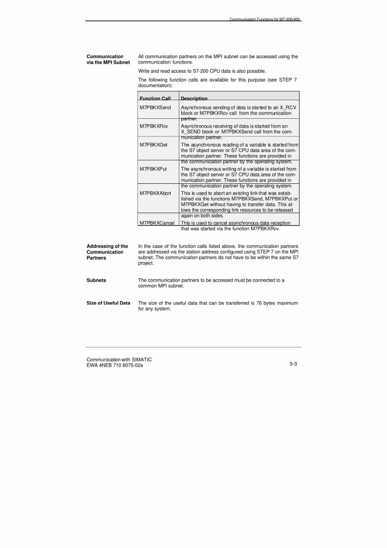
8/20/2019 Communication With Simatic Net
http://slidepdf.com/reader/full/communication-with-simatic-net 95/200
Communication Functions for M7-300/400
Communication with SIMATICEWA 4NEB 710 6075-02a 5-3
Communicationvia the MPI Subnet
All communication partners on the MPI subnet can be accessed using thecommunication functions.
Write and read access to S7-200 CPU data is also possible.
The following function calls are available for this purpose (see STEP 7documentation):
Function Call Description
M7PBKXSend Asynchronous sending of data is started to an X_RCVblock or M7PBKXRcv call from the communicationpartner.
M7PBKXRcv Asynchronous receiving of data is started from anX_SEND block or M7PBKXSend call from the com-munication partner.
M7PBKXGet The asynchronous reading of a variable is started fromthe S7 object server or S7 CPU data area of the com-munication partner. These functions are provided inthe communication partner by the operating system.
M7PBKXPut The asynchronous writing of a variable is started fromthe S7 object server or S7 CPU data area of the com-munication partner. These functions are provided inthe communication partner by the operating system.
M7PBKXAbort This is used to abort an existing link that was estab-lished via the functions M7PBKXSend, M7PBKXPut orM7PBKXGet without having to transfer data. This al-lows the corresponding link resources to be releasedagain on both sides.
M7PBKXCancel This is used to cancel asynchronous data receptionthat was started via the function M7PBKXRcv.
Addressing of theCommunicationPartners
In the case of the function calls listed above, the communication partnersare addressed via the station address configured using STEP 7 on the MPIsubnet. The communication partners do not have to be within the same S7project.
Subnets The communication partners to be accessed must be connected to acommon MPI subnet.
Size of Useful Data The size of the useful data that can be transferred is 76 bytes maximumfor any system.

8/20/2019 Communication With Simatic Net
http://slidepdf.com/reader/full/communication-with-simatic-net 96/200
Communication Functions for M7-300/400
Communication with SIMATICEWA 4NEB 710 6075-02a5-4
CommunicationWithin a SIMATICStation
Using the following function calls, you can access communication partnerswithin a station (e.g. function modules (FMs) in the central rack or in an ET200M). Within a SIMATIC station, you can only use one-sided communi-
cation functions via non-configured links.The following function calls are available for this purpose (see STEP 7documentation):
Function Call Description
M7PBKIGet The asynchronous reading of a variable is initiatedfrom the S7 object server or S7 CPU data area of thecommunication partner. This function is provided in thecommunication partner by the operating system.
M7PBKIPut The asynchronous writing of a variable is started fromthe S7 object server or S7 CPU data area of the com-munication partner. This function is provided in thecommunication partner by the operating system.
M7PBKIAbort This is used to abort an existing link that was estab-lished via the functions M7PBKIPut or M7PBKIGetwithout having to transfer data. This allows the corre-sponding link resources to be released again on bothsides.
Addressing of theCommunicationPartner
In the case of the function calls listed above, the communication partnersare addressed via the module start address configured using STEP 7.
Size of Useful Data The size of the useful data that can be transferred is 76 bytes maximumfor any system.

8/20/2019 Communication With Simatic Net
http://slidepdf.com/reader/full/communication-with-simatic-net 97/200
Communication Functions for M7-300/400
Communication with SIMATICEWA 4NEB 710 6075-02a 5-5
5.2 Communication Functions for Configured S7 Links
Overview The function calls for configured links can be used to exchange largequantities of data (up to 64 Kbytes) between an M7 CPU/FM and anothermodule with communication capability. You can access communicationpartners in different subnets (MPI, PROFIBUS, Industrial Ethernet) as wellas communication partners within the same station.
The communication functions are not limited to data transfer - additionalfunctions can also be used to control and monitor the communicationpartner.
Links Configured links are necessary for communication purposes. These linksare set up using STEP 7.
Links can be assigned to two categories depending on their availability:• Static links are always available. They are established by the operat-
ing system. The maximum number is limited by the system re-sources.
• Dynamic links are only established in response to a user programrequest. The number of links that can be configured is therefore notlimited.
Link Resources If no spare resources are available on the CPU, a new link cannot be es-tablished (temporary resource shortage).
Subnets The communication partners to be accessed must be on a common MPIsubnet, PROFIBUS subnet or Industrial Ethernet.

8/20/2019 Communication With Simatic Net
http://slidepdf.com/reader/full/communication-with-simatic-net 98/200
Communication Functions for M7-300/400
Communication with SIMATICEWA 4NEB 710 6075-02a5-6
Size of Useful Data The size of the useful data that can be transferred depends on the type ofblock used and the communication partner.
Block M7-300/400 toS7-300 (server)
M7-300/400 toS7-400
M7-300/400 toM7-300/400
M7PBKGet / M7PBKPut / M7BUBCycRead / M7BUBRead / M7BUBWrite
160 bytes 1) 400 bytes 1) 880 bytes 1)
M7PBKUSend / M7PBKURcv
- 440 bytes 920 bytes 1)
M7PBKBsend / M7PBKBrcv
- 64 Kbytes 64 Kbytes
1)Total size of the useful data for an SFB with 1 to 4 variables (see STEP 7
documentation).
Addressing The communication partner is addressed via the local link end point (localID). The local ID is generated by STEP 7 when the link is configured. Thecommunication partner does not have to be within the same S7 project.

8/20/2019 Communication With Simatic Net
http://slidepdf.com/reader/full/communication-with-simatic-net 99/200
Communication Functions for M7-300/400
Communication with SIMATICEWA 4NEB 710 6075-02a 5-7
ParallelArrangement ofthe
CommunicationFunctions
Several communication SFBs can be executed simultaneously via a link.This is possible with the communication functionsM7PBKBsend/M7PBKBrcv or M7PBKUsend/M7PBKUrcv.
Using R_ID (block parameter) you can allocate a send and receive func-tion to the same link (same value in each case for R_ID).
Figure 5-1: Several Communication SFBs via One Link
Function Classes The communication calls can be categorized as follows:
•
Functions for link management• Send and receive functions
• Control functions
• Query and monitoring functions
• Functions for the human-machine interface
Functions for LinkManagement
You can use these calls for:
• Creating and closing the application relation for communication
• Querying information concerning the link, e.g. the size of useful data
SFB13R_ID=2
SFB12R_ID=1
SFB8R_ID=3
SFB12 R_ID=2
SFB13
Link
R_ID=1
ID
ID
SFB9 R_ID=3

8/20/2019 Communication With Simatic Net
http://slidepdf.com/reader/full/communication-with-simatic-net 100/200
Communication Functions for M7-300/400
Communication with SIMATICEWA 4NEB 710 6075-02a5-8
Function Call Description
M7KInitiate Creates the application relation for communi-cation
M7KAbort Closes an application relation
M7GetPduSize Queries the maximum size of useful data in-cluding the header
M7GetConnStatus Queries the status of the application relation
M7KPassword Log on for functions with a special protectionlevel
Send and ReceiveFunctions
You can use these communication functions to exchange data betweentwo communication partners.
The following function calls are available for this purpose:
Function Call Description
M7PBKBrcv Receives data, block-oriented: Asynchronous recep-tion of data is started from a B_SEND block orM7PBK B_SEND call from the communication part-ner.
M7PBKBsend Sends data, block-oriented: Asynchronous sending ofdata is started to a B_RCV block or M7PBKBrcv callfrom the communication partner.
M7PBKUSend Uncoordinated sending: Asynchronous sending ofdata is started to a U_RCV block or M7PBKURcv callfrom the communication partner.
M7PBKURcv Uncoordinated receipt of data: Asynchronous receiv-ing of data is started from a U_SEND block orM7PBKUSend call from the communication partner.
M7PBKGet The asynchronous reading of a variable is startedfrom the S7 object server or S7 CPU data area of thecommunication partner. This function is provided inthe communication partner by the operating system.
M7PBKPut The asynchronous writing of a variable is startedfrom the S7 object server or S7 CPU data area of thecommunication partner. This function is provided inthe communication partner by the operating system.
M7PBKCancel The currently active send or receive task
(M7PBKBsend, M7PBKBrcv) is aborted.

8/20/2019 Communication With Simatic Net
http://slidepdf.com/reader/full/communication-with-simatic-net 101/200
Communication Functions for M7-300/400
Communication with SIMATICEWA 4NEB 710 6075-02a 5-9
Control Functions You can use these calls to send commands to change status to a commu-nication partner:
Function Call Description
M7PBKResume This triggers a warm restart for an S7-400CPU when it is in the STOP state
M7PBKStart This triggers a complete restart for anM7/S7-300/400 CPU when it is in the STOPstate.
M7PBKStop This stops an M7/S7-300/400 CPU when it isin the RUN, HALT or start-up state.
Query andMonitoringFunctions
You can use these calls to
• Request information concerning the communication partner
• Read or set the time for a communication partner
• Output calls to the diagnostics server (the diagnostics server allowsan application on the SIMATIC M7 to log itself on for diagnosticssignals output by a distant controller)
Function Call Description
M7PBKStatus Outputs the operating status of a communica-tion partner
M7DiagMode Logs on or off for diagnostics
M7KEvent Fetches data for asynchronous messages
M7KReadTime Reads the time
M7KWriteTime Sets the time

8/20/2019 Communication With Simatic Net
http://slidepdf.com/reader/full/communication-with-simatic-net 102/200
Communication Functions for M7-300/400
Communication with SIMATICEWA 4NEB 710 6075-02a5-10
Functions forOperator Controland Visualization
You can use the M7-API calls for operator control and visualization to im-plement your own HMI applications on the M7 automation computer.
M7-API provides, for example, functions for reading and writing or cyclicreading of variables from a distant programmable controller.
Function Call Description
M7BUBCycRead Task for setting up a cyclic read
M7BUBCycReadDelete Task for deleting a cyclic read
M7BUBCycReadStart Task for starting a cyclic read
M7BUBCycReadStop Task for stopping a cyclic read
M7BUBRead Read HMI variables
M7BUBWrite Write HMI variables

8/20/2019 Communication With Simatic Net
http://slidepdf.com/reader/full/communication-with-simatic-net 103/200
Cyclic Communication for S7/M7/C7-300/400
Communication with SIMATICEWA 4NEB 710 6075-02a 6-1
6 Cyclic Communication for S7/M7/C7-300/400
Overview In this Chapter you will find an explanation of cyclic communication.
Chapter Overview In Section You will find On page
6.1 Introduction 6-2
6.2 Global Data Communication (GD) 6-3
6.3 Distributed I/O via PROFIBUS-DP 6-7
6.4 Distributed I/O via the AS-i bus 6-9

8/20/2019 Communication With Simatic Net
http://slidepdf.com/reader/full/communication-with-simatic-net 104/200
Cyclic Communication for S7/M7/C7-300/400
Communication with SIMATICEWA 4NEB 710 6075-02a6-2
6.1 Introduction
Definition In cyclic communication, the configured global data (e.g. bit memories,timers, counters and inputs/outputs) are only transferred, like the processimage, once during cyclic program processing (OB1).
Cyclic Communication
Services Configured via Software Pack-ages
Global data com-munication, GD
GD table(MPI subnet -> Configure globaldata)
STEP 7
Distributed I/O,PROFIBUS-DP
STEP 7 hardware configuration STEP 7
Distributed I/O viaAS-i bus
AS-i CP with STEP 7 hardwareconfiguration
STEP 7
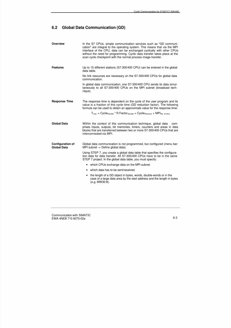
8/20/2019 Communication With Simatic Net
http://slidepdf.com/reader/full/communication-with-simatic-net 105/200
Cyclic Communication for S7/M7/C7-300/400
Communication with SIMATICEWA 4NEB 710 6075-02a 6-3
6.2 Global Data Communication (GD)
Overview In the S7 CPUs, simple communication services such as "GD communi-cation" are integral to the operating system. This means that via the MPIinterface of the CPU, data can be exchanged cyclically with other CPUswithout the need for programming. Cyclic data transfer takes place at thescan cycle checkpoint with the normal process image transfer.
Features Up to 15 different stations (S7-300/400 CPU) can be entered in the globaldata table.
No link resources are necessary on the S7-300/400 CPUs for global datacommunication.
In global data communication, one S7-300/400 CPU sends its data simul-
taneously to all S7-300/400 CPUs on the MPI subnet (broadcast tech-nique).
Response Time The response time is dependent on the cycle of the user program and itsvalue is a fraction of this cycle time (GD reduction factor). The followingformula can be used to obtain an approximate value for the response time:
Tmax. = CycleSender * R FactorSender + CycleReceiver + MPINo. of stns.
Global Data Within the context of this communication technique, global data com-prises inputs, outputs, bit memories, timers, counters and areas in datablocks that are transferred between two or more S7-300/400 CPUs that are
interconnected via MPI.
Configuration ofGlobal Data
Global data communication is not programmed, but configured (menu bar:MPI subnet -> Define global data).
Using STEP 7, you create a global data table that specifies the configura-tion data for data transfer. All S7-300/400 CPUs have to be in the sameSTEP 7 project. In the global data table, you must specify:
• which CPUs exchange data on the MPI subnet.
• which data has to be sent/received.
• the length of a GD object in bytes, words, double-words or in thecase of a large data area by the start address and the length in bytes(e.g. MW30:8).

8/20/2019 Communication With Simatic Net
http://slidepdf.com/reader/full/communication-with-simatic-net 106/200
Cyclic Communication for S7/M7/C7-300/400
Communication with SIMATICEWA 4NEB 710 6075-02a6-4
The following information can be entered if applicable:
• a reduction factor that specifies the number of program cycles afterwhich the data should be sent/received
• a data area for the status information.
Cyclic Transfer ofGlobal Data
The CPU sends the global data at the end of a cycle and reads this dataat the beginning of a cycle. By stating a reduction factor in the global datatable, you can specify the number of cycles after which data should betransmitted or received.
GD Packet Global data that is transmitted from one sender to the same receivers isgrouped into one GD packet. The GD packet is sent in a telegram. A GDpacket is identified by a GD packet number. If the maximum length of asend GD packet is exceeded, a new GD circle is used.
GD Circle The CPUs that are involved in the transfer of a common GD packet form aGD circle. If other CPUs are connected to an MPI subnet that exchangeother GD packets, they form a second GD circle. Different circles can ac-cess the same CPU, i.e. they are permitted to overlap.
Figure 6-1: Example to Show GD Circles and GD Packets
Example The GD table corresponding to the above example is shown below.
Global Data for Subnet "Example/MPI-Net1"
GD Identifier CPU 1 CPU 2 CPU 3 CPU 4GD 1.1.1 >>MB100 MB100 MB100
GD 1.1.2 >>MB100 EB100 EB102
GD 2.1.1 >>MW120 AW40 EW40
GD 3.1.1 MW30:8 >>MW30:8
CPU1 CPU2 CPU3 CPU4
GD packet A
GD packet B
GD packet C
MPI subnet
GD circle 1
GD circle 2
GD circle 3

8/20/2019 Communication With Simatic Net
http://slidepdf.com/reader/full/communication-with-simatic-net 107/200
Cyclic Communication for S7/M7/C7-300/400
Communication with SIMATICEWA 4NEB 710 6075-02a 6-5
Note All CPUs must have a unique name because only the name is shown inthe GD table (each S7 CPU only has the type name CPU314(1) as stan-dard).
GD Identifier When the GD table has been successfully translated for the first time, thefollowing identifier is assigned to the first column of global data:
GD Resources ofthe CPUs
The GD resources for a CPU are defined as the maximum number of GDcircles in which the CPU is able to participate. Refer to the following tableto find out what GD resources are available to your CPU.
GD Resources CPU 312CPU 313CPU 314CPU 315
CPU 412CPU 413CPU 414
CPU 416
Max. No. of GD circles per CPU 4 8 16
Max. No. of receive GD packetsfor all GD circles 4 16 32
Max. No. of send GD packetsper GD circle
1 1 1
Max. No. of receive GD packetsper GD circle
1 2 2
Max. No. of send GD packetsfor all GD circles
4 8 16
Max. length of GD packet 1) 22 bytes 54 bytes 54 bytes
Reduction factor 1 to 225 1 to 255 1 to 255
Event-driven data transfer No Yes Yes
1) The values in the table are based on one variable. The maximum size of useful data per GDpacket is reduced by 2 bytes for each additional variable.
GD 1.1.2
Number of variables in GD packet
Number of GD packet
Number of GD circle

8/20/2019 Communication With Simatic Net
http://slidepdf.com/reader/full/communication-with-simatic-net 108/200
Cyclic Communication for S7/M7/C7-300/400
Communication with SIMATICEWA 4NEB 710 6075-02a6-6
Data Consistency The maximum quantity of data that can be transferred consistently de-pends on the type of CPU as follows:
CPU 31x CPU 412 CPU 413 CPU 414 CPU 4168 bytes 32 bytes 32 bytes 32 bytes 32 bytes
Event-DrivenGlobal DataTransfer
You can use the SFC 60 GD_SND and SFC 61 GD_RCV system functionsto send or receive GD packets, in contrast to cyclic transfer, at any re-quired point in the user program. The prerequisite, however, is that youhave configured data transmission, i.e. that you have created a global datatable.
As parameters of the SFCs, specify the numbers of the GD circle and GDpacket that were generated when the global data table was configured.
If you specify zero as the reduction factor in the global data table, theglobal data is only transferred when the appropriate SFCs are called.

8/20/2019 Communication With Simatic Net
http://slidepdf.com/reader/full/communication-with-simatic-net 109/200
Cyclic Communication for S7/M7/C7-300/400
Communication with SIMATICEWA 4NEB 710 6075-02a 6-7
6.3 Distributed I/O via PROFIBUS-DP
Overview The "distributed I/O" is an expansion unit fitted with I/O modules that areconnected via a parallel bus (via an IM) or via a serial bus (interface onCPU, IM or CP) to a central controller. The serial bus is PROFIBUS-DP,which handles open communication up to Layer 7 in accordance with theEN 50170 standard (Vol. 2, PROFIBUS-DP).
This PROFIBUS-DP interface is integrated in the CPUs or a separate in-terface (IM or CP) is used. The I/O that is connected to PROFIBUS as aDP slave in the expansion unit (ET 200 station) is addressed in the samemanner as every other I/O in the central controller or expansion unit. Thismeans that you can access the I/O modules directly with instructions or viaprocess image transfer.
Features Up to 125 PROFIBUS DP slave stations can be connected to one DPmaster (e.g. CPU). The number depends on the type of CPU used.
The distributed I/O can be accessed via the integral PROFIBUS-DP inter-face or via a PROFIBUS-CP or an IM.
Parameters are assigned using STEP 7.
The programming devices can also be connected via PROFIBUS.
PROFIBUS-DP andSIMATIC-S7/M7
In SIMATIC S7/M7, the integrated PROFIBUS-DP interface in the CPU issupplemented with separate interfaces.
Interfacing for SIMATIC S7:
• CPU 315-2 DP in S7-300 via integrated PROFIBUS-DP interface(master/slave)
• CPU 413-2 DP or CPU 414-2DP and CPU 416-2DP in S7-400 viaintegrated PROFIBUS-DP interface (only master)
For the purpose of interfacing to PROFIBUS-DP in the case of SIMATICM7, the IF 964-DP interface submodule is available which is plugged intothe multifunctional interface (MFI).
• CPU 388-4 in M7-300 or with the FM 356 function module (master).The IF 964-DP interface submodule is plugged into the MFI in anexpansion module (EXM).

8/20/2019 Communication With Simatic Net
http://slidepdf.com/reader/full/communication-with-simatic-net 110/200
Cyclic Communication for S7/M7/C7-300/400
Communication with SIMATICEWA 4NEB 710 6075-02a6-8
• CPUs 488-4 and 488-5 in M7-400 or with the FM 456-4 functionmodule (master).The IF 964-DP interface submodule can be plugged into the MFI ofthese modules or into the MFI of the connected expansion module(EXM).
AS-i Link See "Distributed I/O via the AS-i bus" in Section 6.4.
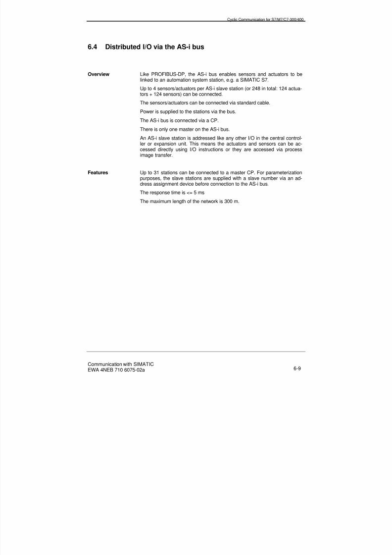
8/20/2019 Communication With Simatic Net
http://slidepdf.com/reader/full/communication-with-simatic-net 111/200
Cyclic Communication for S7/M7/C7-300/400
Communication with SIMATICEWA 4NEB 710 6075-02a 6-9
6.4 Distributed I/O via the AS-i bus
Overview Like PROFIBUS-DP, the AS-i bus enables sensors and actuators to belinked to an automation system station, e.g. a SIMATIC S7.
Up to 4 sensors/actuators per AS-i slave station (or 248 in total: 124 actua-tors + 124 sensors) can be connected.
The sensors/actuators can be connected via standard cable.
Power is supplied to the stations via the bus.
The AS-i bus is connected via a CP.
There is only one master on the AS-i bus.
An AS-i slave station is addressed like any other I/O in the central control-ler or expansion unit. This means the actuators and sensors can be ac-
cessed directly using I/O instructions or they are accessed via processimage transfer.
Features Up to 31 stations can be connected to a master CP. For parameterizationpurposes, the slave stations are supplied with a slave number via an ad-dress assignment device before connection to the AS-i bus.
The response time is <= 5 ms
The maximum length of the network is 300 m.

8/20/2019 Communication With Simatic Net
http://slidepdf.com/reader/full/communication-with-simatic-net 112/200
Cyclic Communication for S7/M7/C7-300/400
Communication with SIMATICEWA 4NEB 710 6075-02a6-10
AS-i Link You can couple the AS-i subnet to the PROFIBUS-DP subnet usingDP/AS-i Link (DP/AS-i link is a master) as a link between PROFIBUS-DPand AS-i.
DP/AS-i link operates as a DP slave on PROFIBUS-DP, i.e. under normaloperating conditions, you do not notice that the AS-i cable is at a lowersystem level (see also Chapter 3).
Figure 6-2: Example of DP/AS-i Link
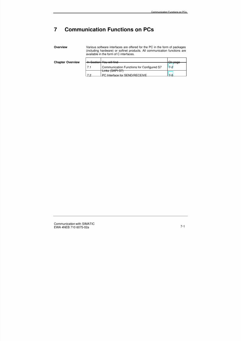
8/20/2019 Communication With Simatic Net
http://slidepdf.com/reader/full/communication-with-simatic-net 113/200
Communication Functions on PCs
Communication with SIMATICEWA 4NEB 710 6075-02a 7-1
7 Communication Functions on PCs
Overview Various software interfaces are offered for the PC in the form of packages(including hardware) or softnet products. All communication functions areavailable in the form of C interfaces.
Chapter Overview In Section You will find On page
7.1 Communication Functions for Configured S7Links (SAPI-S7)
7-2
7.2 PC Interface for SEND/RECEIVE 7-5

8/20/2019 Communication With Simatic Net
http://slidepdf.com/reader/full/communication-with-simatic-net 114/200
Communication Functions on PCs
Communication with SIMATICEWA 4NEB 710 6075-02a7-2
7.1 Communication Functions for Configured S7 Links (SAPI-S7)
Overview You can use the S7 functions for the PC (SAPI-S7) to exchange databetween a PC and an S7/M7CPU/FM. Communication partners can beaccessed in different subnets (MPI, PROFIBUS, Industrial Ethernet).
This is not limited to data transfer: control and monitoring functions canalso be used.
SAPI-S7 (simple application programmers interface) is the C program-ming interface for accessing the S7 on the programming device or PC(communication service).
The SAPI-S7 interface is offered for various operating systems and hard-ware platforms (see Catalog IK 10).
Features The services of the S7 functions can be processed on the PC and in thecomputer world.
• The SAPI-S7 programming interface is designed asynchronously.
• SAPI-S7 processes communication services as well as connectingand disconnecting links automatically.
• SAPI-S7 supports troubleshooting with an integrated trace function.
• The SAPI-S7 programming interface can also be used, for example,via VisualBASIC or Pascal programs.
Links Configured S7 links are required for communication. The links are config-ured exclusively on the PC (e.g. using COML S7).
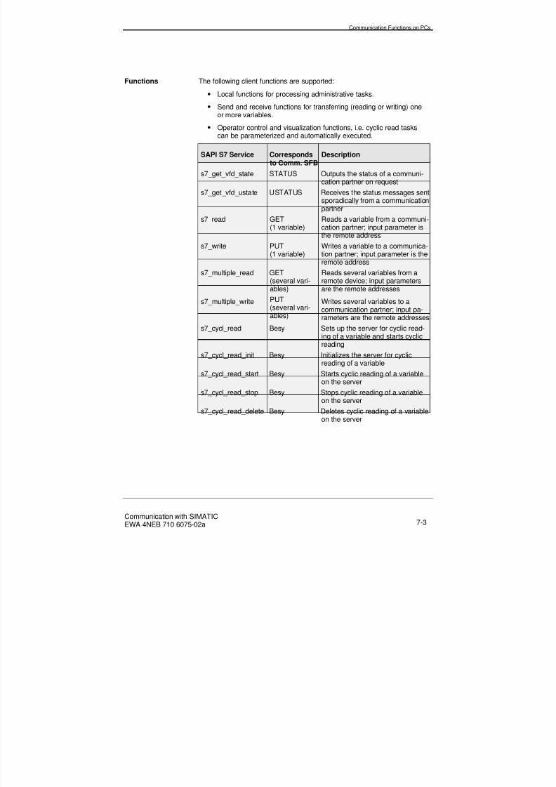
8/20/2019 Communication With Simatic Net
http://slidepdf.com/reader/full/communication-with-simatic-net 115/200
Communication Functions on PCs
Communication with SIMATICEWA 4NEB 710 6075-02a 7-3
Functions The following client functions are supported:
• Local functions for processing administrative tasks.
• Send and receive functions for transferring (reading or writing) oneor more variables.
• Operator control and visualization functions, i.e. cyclic read taskscan be parameterized and automatically executed.
SAPI S7 Service Correspondsto Comm. SFB
Description
s7_get_vfd_state STATUS Outputs the status of a communi-cation partner on request
s7_get_vfd_ustate USTATUS Receives the status messages sentsporadically from a communicationpartner
s7_read GET(1 variable)
Reads a variable from a communi-cation partner; input parameter isthe remote address
s7_write PUT(1 variable)
Writes a variable to a communica-tion partner; input parameter is theremote address
s7_multiple_read GET(several vari-ables)
Reads several variables from aremote device; input parametersare the remote addresses
s7_multiple_write PUT(several vari-
ables)
Writes several variables to acommunication partner; input pa-
rameters are the remote addressess7_cycl_read Besy Sets up the server for cyclic read-
ing of a variable and starts cyclicreading
s7_cycl_read_init Besy Initializes the server for cyclicreading of a variable
s7_cycl_read_start Besy Starts cyclic reading of a variableon the server
s7_cycl_read_stop Besy Stops cyclic reading of a variableon the server
s7_cycl_read_delete Besy Deletes cyclic reading of a variableon the server

8/20/2019 Communication With Simatic Net
http://slidepdf.com/reader/full/communication-with-simatic-net 116/200
Communication Functions on PCs
Communication with SIMATICEWA 4NEB 710 6075-02a7-4
Size of Useful Data The maximum size of useful data that can be transferred depends on thetype of communication function used and the communication partner.
Block PC toS7-300 (Server)
PC toS7-400
PC to M7-300/400
s7_read 222 bytes 1) 462 bytes 1) 942 bytes 1)
s7_write 212 bytes 1) 452 bytes 1) 932 bytes 1)
s7-cycl_read 208 bytes 1) 448 bytes 1) 928 bytes 1)
1)The values in the table are based on one variable. The maximum size of useful data is re-
duced by 4 bytes for a read and 14 bytes for a write for each additional variable.
Data Consistency This is the maximum data area that can be read or written in the case ofS7-300/400 CPUs as a continuous block.
An array of the data types byte, word and double-word can be transferredconsistently up to a maximum length which is specific to the CPU used asfollows:
CPU 31x CPU 412 CPU 413 CPU 414 CPU 416
8 bytes 32 bytes 32 bytes 32 bytes 32 bytes
Addressing The communication partner is addressed via the local link end point.
When the link is configured using COML S7, the address parameters(station address and rack/slot for SIMATIC S7/M7) of the communicationpartner has to be entered.

8/20/2019 Communication With Simatic Net
http://slidepdf.com/reader/full/communication-with-simatic-net 117/200
Communication Functions on PCs
Communication with SIMATICEWA 4NEB 710 6075-02a 7-5
7.2 PC Interface for SEND/RECEIVE
Overview You can use the SEND/RECEIVE programming interface to communicatewith the SIMATIC systems from the PC.
The SEND/RECEIVE interface is the C programming interface for accessto the FDL, ISO transport and ISO-on-TCP services.
Communication partners can be accessed in the PROFIBUS and Indus-trial Ethernet subnets.
The SEND/RECEIVE interface is offered for various operating systemsand hardware platforms (see Catalog IK 10).
Features The SEND/RECEIVE programming interface is a simple interface for ex-changing data with any communication partners on the basis of standard-
ized communication services.
Links Configured FDL, ISO transport and ISO-on-TCP links are required forcommunication. The links are configured on the PC (e.g. using COML1413) and on SIMATIC S7 with STEP 7 using the appropriate optionspackage (NCM S7 PROFIBUS, NCM S7 Industrial Ethernet).
The links can be established and removed, program-driven from the PC.
Functions The following functions are supported:
Function Description
SEND_DATA Sends data blocks via a configured link to thecommunication partner
RECEIVE_DATA Receives data blocks via a configured link from thecommunication partner
CONN Establishes a link to the communication partner
CLOSE Removes a link to the communication partner
Size of Useful Data The maximum size of useful data that can be transferred to SIMATIC S7is 240 bytes for all types of subnet.
Data Consistency In the case of SIMATIC S7, useful data of up to 240 bytes can be trans-ferred consistently.

8/20/2019 Communication With Simatic Net
http://slidepdf.com/reader/full/communication-with-simatic-net 118/200
Communication Functions on PCs
Communication with SIMATICEWA 4NEB 710 6075-02a7-6
Link Resources Since in this case the links are configured, the configuring tool (e.g. COML1413) checks at the configuration stage whether one link resource is stillavailable.
Addressing The communication partner is selected via the configured S7 link.

8/20/2019 Communication With Simatic Net
http://slidepdf.com/reader/full/communication-with-simatic-net 119/200
Connecting SIMATIC Programming Devices/OPs
Communication with SIMATICEWA 4NEB 710 6075-02a 8-1
8 Connecting SIMATIC Programming Devices/OPs
Overview In this Chapter, you will find out how to connect programming devices andhuman-machine interfaces and how to use TeleService.
Chapter Overview In Section You will find On page
8.1 Programming Device/PC Interfacing for STEP 7on Subnets
8-2
8.2 SIMATIC OP Interface to Subnets 8-4
8.3 TeleService 8-6

8/20/2019 Communication With Simatic Net
http://slidepdf.com/reader/full/communication-with-simatic-net 120/200
Connecting SIMATIC Programming Devices/OPs
Communication with SIMATICEWA 4NEB 710 6075-02a8-2
8.1 Programming Device/PC Interfacing for STEP 7 on Subnets
Overview When a programming device is used with STEP 7 onMPI/PROFIBUS/Ethernet, the complete functional scope of STEP 7 isavailable as well as the functions for SIMATIC S7 programming, diag-nostics and HMI.
Features of STEP 7Online Mode
For online mode via MPI, a separate interface is not required for the pro-gramming device (integral).
In online mode for programming devices/PCs via PROFIBUS/Ethernet, aPROFIBUS/Ethernet CP has to be installed in the programming device.
Subnet Programming device with
STEP 7
PC with STEP 7
MPI - MPI card (ISA)CP 5412-A2 (ISA)CP 5411 (ISA)CP 5511 (PCMCIA)CP 5611 (PCI)
PROFIBUS CP 5412 A2 (ISA)CP 5411 (ISA)CP 5511 (PCMCIA)CP 5611 (PCI)
CP 5412 A2 (ISA)CP 5411 (ISA)CP 5511 (PCMCIA)CP 5611 (PCI)
Ethernet CP 1413 ISA)CP 1411 (ISA)CP 1511 (PCMCIA)
CP 1413 ISA)CP 1411 (ISA)CP 1511 (PCMCIA)
Note An address has to be assigned to the CPs in the stations (node christen-ing via MPI) to prepare them for online mode via PROFIBUS/Ethernetsubnets.
Procedure To use programming device mode via PROFIBUS/Ethernet, proceed asfollows:
• In the Windows 95 system setup, open the dialog field "Set up pro-gramming device/PC interface".
• Set up the programming device/PC interface in accordance with theCPs available on your programming device ("Device parameters"field) and in accordance with the bus interface ("Characteristics"field). Please ensure that you enter consistent bus parameters.

8/20/2019 Communication With Simatic Net
http://slidepdf.com/reader/full/communication-with-simatic-net 121/200
Connecting SIMATIC Programming Devices/OPs
Communication with SIMATICEWA 4NEB 710 6075-02a 8-3
Once you have carried out these steps, the programming device viaPROFIBUS/Ethernet automatically finds its way to all intelligent modulesin the SIMATIC S7 stations.
Link Resources One link resource is required on the S7/M7 CPU for each programmingdevice/PC link. By default, one link resource is permanently reserved ineach S7/M7 CPU. One more spare link resource is required for eachadditional programming device/PC link.
ProgrammingDevices onPROFIBUS-DP
Via PROFIBUS-DP, you can program and parameterize the CPUs of thecontrollers and carry out diagnostics from any point in a plant.
No additional programming device interface is necessary, becausePG 720, PG 740 and PG 760 have an integral PROFIBUS-DP interfacewith a transmission rate of 1.5 Mbit/s.
A PROFIBUS-CP is available for higher transmission rates (up to 12Mbit/s).
PCs onPROFIBUS-DP
If you want to program SIMATIC S7 or start it up via PROFIBUS using aPC, you will need a PC interface.
The transmission rate of the PROFIBUS-CP in the PC is 12 Mbit/s max.

8/20/2019 Communication With Simatic Net
http://slidepdf.com/reader/full/communication-with-simatic-net 122/200
Connecting SIMATIC Programming Devices/OPs
Communication with SIMATICEWA 4NEB 710 6075-02a8-4
8.2 SIMATIC OP Interface to Subnets
Overview The SIMATIC human machine interfaces can be connected viaMPI/PROFIBUS/Industrial Ethernet.
MPI/PROFIBUS/Ethernet
PG/PC
CP
S7-300
S7-300
OP
OP S7-400
Figure 8-1: Stations on the Subnet
Features Communication between the OP and SIMATIC S7/M7 takes place via theS7 functions and is fully supported by the operating system of the CPU.For this reason, function blocks are not required on the SIMATIC S7/M7.
The OP and SIMATIC S7/M7 communicate via user program data areasthat have to be created in SIMATIC S7/M7. These data areas include, forexample, messages, recipes and curves.
An OP can exchange data simultaneously with more than one communi-cation partner (e.g. CPU or FM).
Link Resources One link resource is required on the S7/M7 CPU for each OP link. By de-fault, one link resource is permanently reserved in each S7/M7 CPU. Onespare link resource is required for each additional OP link.

8/20/2019 Communication With Simatic Net
http://slidepdf.com/reader/full/communication-with-simatic-net 123/200
Connecting SIMATIC Programming Devices/OPs
Communication with SIMATICEWA 4NEB 710 6075-02a 8-5
Interface to S7/M7 MPI PROFIBUS Ethernet
Integralinterface
Integral DPinterface
CP342-5,CP443-5
CP343-1CP443-1
Max. no. of links to CPU/FM
OP3
OP5OP15OP25OP35OP7OP17OP37
-
OP5OP15OP25OP35OP7OP17OP37
-
OP5OP15OP25OP35OP7OP17OP37
2 S7-200/300
4 S7/M7-300/4004 S7/M7-300/4004 S7/M7-300/4006 S7/M7-300/4004 S7/M7-300/4004 S7/M7-300/4008 S7/M7-300/400
ProTool ProTool ProTool
OP47 OP47 OP47 OP47 8 S7/M7-300/400
WINCC
PCs can be connected via Industrial Ethernet with WIN CC.
Configuration The only requirement is that the communication partner has to be se-lected using ProTool. No other configuration is necessary.
Operator Panels(OPs)
OPs are not DP stations. The OPs use the S7 functions and not thePROFIBUS-DP functions.
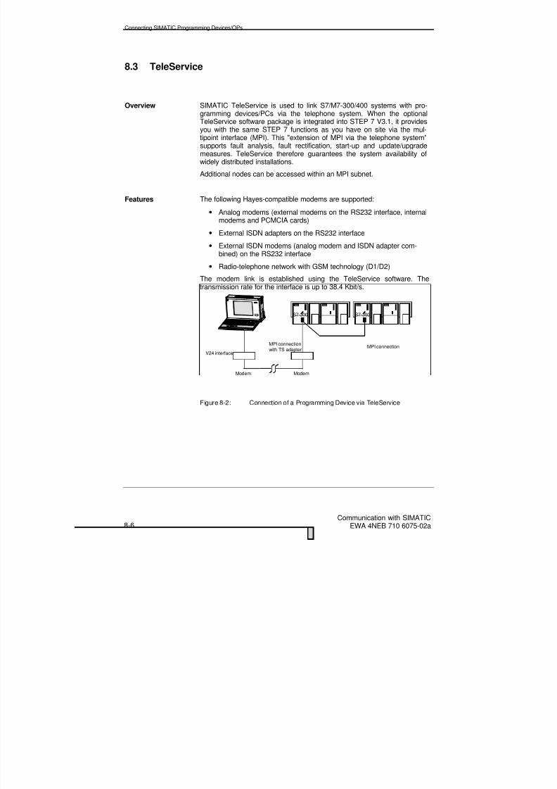
8/20/2019 Communication With Simatic Net
http://slidepdf.com/reader/full/communication-with-simatic-net 124/200
Connecting SIMATIC Programming Devices/OPs
Communication with SIMATICEWA 4NEB 710 6075-02a8-6
8.3 TeleService
Overview SIMATIC TeleService is used to link S7/M7-300/400 systems with pro-gramming devices/PCs via the telephone system. When the optionalTeleService software package is integrated into STEP 7 V3.1, it providesyou with the same STEP 7 functions as you have on site via the mul-tipoint interface (MPI). This "extension of MPI via the telephone system"supports fault analysis, fault rectification, start-up and update/upgrademeasures. TeleService therefore guarantees the system availability ofwidely distributed installations.
Additional nodes can be accessed within an MPI subnet.
Features The following Hayes-compatible modems are supported:
• Analog modems (external modems on the RS232 interface, internalmodems and PCMCIA cards)
• External ISDN adapters on the RS232 interface
• External ISDN modems (analog modem and ISDN adapter com-bined) on the RS232 interface
• Radio-telephone network with GSM technology (D1/D2)
The modem link is established using the TeleService software. Thetransmission rate for the interface is up to 38.4 Kbit/s.
V24 interface
S7-300
MPI connectionwith TS adapter
Modem Modem
S7-300
MPI connection
Figure 8-2: Connection of a Programming Device via TeleService

8/20/2019 Communication With Simatic Net
http://slidepdf.com/reader/full/communication-with-simatic-net 125/200
Connecting SIMATIC Programming Devices/OPs
Communication with SIMATICEWA 4NEB 710 6075-02a 8-7
Requirements The prerequisite is that a physical connection between the programmingdevice and the SIMATIC system exists (V24 interface of the program-ming device -> Modem -> Public telephone system -> Modem -> TS
adapter -> MPI interface of the target system).The SIMATIC system is physically connected to the modem via the TSadapter with a multipoint interface.

8/20/2019 Communication With Simatic Net
http://slidepdf.com/reader/full/communication-with-simatic-net 126/200
8/20/2019 Communication With Simatic Net
http://slidepdf.com/reader/full/communication-with-simatic-net 127/200
Project Engineering and Configuring with STEP 7
Communication with SIMATICEWA 4NEB 710 6075-02a 9-1
9 Project Engineering and Configuring with
STEP 7
Overview In this Chapter, building on basic STEP 7 know-how, you will find out howto solve your communication task, i.e. how to create subnets in S7 proj-ects and how to configure links. You will become familiar with the STEP 7address assignment concept.
Chapter Overview In Section You will find On page
9.1 S7 Project 9-2
9.2 Specifying the Network Configuration 9-3
9.3 Address Assignment 9-59.4 Link Resources 9-8
9.5 Configuring Links 9-13

8/20/2019 Communication With Simatic Net
http://slidepdf.com/reader/full/communication-with-simatic-net 128/200
Project Engineering and Configuring with STEP 7
Communication with SIMATICEWA 4NEB 710 6075-02a9-2
9.1 S7 Project
Overview An S7 project represents the sum total of all data and programs, includingthe subnets of an automation solution, that are required to communicatewith each other. The data that is contained within a project comprises inparticular:
• Data describing the hardware configuration and parameterizationdata for the modules
• Configuration data for the subnets and the links
• Programs for programmable modules.
This provides far-reaching possibilities for re-using components that havebeen developed previously for an automation solution. If you copy an S7project, all lower hierarchic levels are also copied.
CP
CP
Subnet
Project
Figure 9-1: Example of a Subnet - A Project
Features The STEP 7 configuration procedure ensures consistency with respect toaddress assignment, bus parameters and baud rates within the communi-cation system.
All communication partners for an automation task should therefore al-ways be grouped together in a project.
8/20/2019 Communication With Simatic Net
http://slidepdf.com/reader/full/communication-with-simatic-net 129/200
Project Engineering and Configuring with STEP 7
Communication with SIMATICEWA 4NEB 710 6075-02a 9-3
9.2 Specifying the Network Configuration
Overview Similar to specifying the hardware configuration, where you configure theindividual stations, on specifying the network configuration, the interac-tion of all communication partners has to be considered and the parame-ters have to be assigned accordingly.
A previously configured network is the basis for communication. Here it isof no consequence whether you want to conduct communication in theuser program via global data or via communication functions.
When the network is configured for an S7 project, all settings are checkedfor plausibility and consistency. Duplicate station addresses or invalid pa-rameters are detected as they are entered.
Network A network comprises one or more coupled subnets of the same or differenttypes. It also comprises all stations that have to communicate with oneanother.
Subnet A subnet (MPI, PROFIBUS, Industrial Ethernet) is the sum total of allphysical components that are required to construct a data transfer path aswell as the associated common technique that is required to exchangedata. The components of a subnet are interconnected without networkgateways. The individual stations are interconnected via the subnet.
A point-to-point link is not defined as a subnet.
Configuring So that stations are able to communicate with each other, the subnetsrequired must be configured in the STEP 7 projects.
A network or subnet configuration is specified by:
• Creating one or more subnets of the types required in the project;
• Specifying the characteristics of the subnets; the default settings areusually sufficient;
• Connecting the station "logically" to the subnet;
• Initializing the communication links.

8/20/2019 Communication With Simatic Net
http://slidepdf.com/reader/full/communication-with-simatic-net 130/200
Project Engineering and Configuring with STEP 7
Communication with SIMATICEWA 4NEB 710 6075-02a9-4
Tools There are three different possibilities for specifying the network configura-tion:
• SIMATIC ManagerFor simple, clearly comprehensible network configurations, theSIMATIC Manager provides all the functions that are necessary forconfiguring and documentation.
• NCM S7 for PROFIBUSThe optional package NCM S7 for PROFIBUS can be used to con-figure communication links via a PROFIBUS subnet.
• NCM S7 for Industrial EthernetThe optional package NCM S7 can be used to configure communi-cation links via an Ethernet subnet.

8/20/2019 Communication With Simatic Net
http://slidepdf.com/reader/full/communication-with-simatic-net 131/200
Project Engineering and Configuring with STEP 7
Communication with SIMATICEWA 4NEB 710 6075-02a 9-5
9.3 Address Assignment
9.3.1 Address Assignment via MPI
Features Each communicating station has a unique MPI address (address range 0to 31).
The MPI address is automatically supplied by STEP 7 (default value) butcan be changed.
S7-300 Every module with communication capability in the S7-300 has a uniqueMPI address that is only permitted to be assigned once on network con-figuration. Only one CPU may be implemented in each rack. Figure 9-2
shows how MPI addresses are assigned within an S7-300 station.
Special Feature When MPI subnets with S7-300 stations are configured, an address is notonly automatically assigned for the S7-300 CPU in the station, an addressis also determined for any FMs and CPs.
FM
Figure 9-2: Example Showing MPI Addresses
The FM or CP module that is in the slot closest to the S7-300 CPU auto-matically receives the MPI address that follows the address already as-signed to the CPU and the next module receives the next address, and soon.

8/20/2019 Communication With Simatic Net
http://slidepdf.com/reader/full/communication-with-simatic-net 132/200
Project Engineering and Configuring with STEP 7
Communication with SIMATICEWA 4NEB 710 6075-02a9-6
S7-400 An MPI address is only assigned to those modules that are fitted with anMPI connector. The MPI address may only be assigned once in the net-work configuration. Modules that are not fitted with an MPI connector are
addressed indirectly via rack/slot number.Figure 9-3 shows a simple configuration with one rack.
MPI addr.
CPU CP
Figure 9-3: Example of S7-400 MPI Address
9.3.2 Address Assignment via PROFIBUS
Features Each communicating station has a unique PROFIBUS address (addressrange 0 to 126). The PROFIBUS address is one byte long.
The PROFIBUS address is automatically supplied by STEP 7 (defaultvalue) but can be changed.

8/20/2019 Communication With Simatic Net
http://slidepdf.com/reader/full/communication-with-simatic-net 133/200
Project Engineering and Configuring with STEP 7
Communication with SIMATICEWA 4NEB 710 6075-02a 9-7
9.3.3 Address Assignment via Ethernet
Features The Ethernet address (MAC address) is 6 bytes long. In the case of Sie-mens systems, it is built up as follows:
080006 01 0 xxx Hex
Significant stationaddress SIEMENSdevice
SIEMENS systemSIMATIC
Number for the
SIEMENS departmentNumber for SIEMENS
Addresses can be assigned to up to 1024 stations per segment.

8/20/2019 Communication With Simatic Net
http://slidepdf.com/reader/full/communication-with-simatic-net 134/200
Project Engineering and Configuring with STEP 7
Communication with SIMATICEWA 4NEB 710 6075-02a9-8
9.4 Link Resources
Introduction Each link requires link resources on the participating stations for the endpoint or for the transition point (e.g. to a CP). The number of link re-sources required depends on the CPU/CP type.
When all the link resources of a communication partner are reserved, anew link can no longer be established.
The different communication types are analyzed separately below. Theycan be combined as required, however, provided that the available linkresources are taken into account.
S7 Functions In the case of the S7 functions via the integral MPI/PROFIBUS-DP inter-face, one link resource per S7 link is reserved on the CPU for the end
point. This applies to all S7/M7-300/400 CPUs.
Figure 9-4: S7 Functions via Integral Interfaces
In the case of S7 functions via an external CP interface, one link resourceper S7 link is reserved on the CPU (for the end point) and one link re-source is reserved on the CP (transition point). This applies to allS7/M7-300/400 CPUs.
Figure 9-5: S7 Functions via CP Interface
CPU
CPU
MPI or PROFIBUS-DP
Industrial EthernetPROFIBUS
CP
Free link resource
Free link resource
Reserved link resource
Reserved link resources

8/20/2019 Communication With Simatic Net
http://slidepdf.com/reader/full/communication-with-simatic-net 135/200
Project Engineering and Configuring with STEP 7
Communication with SIMATICEWA 4NEB 710 6075-02a 9-9
SEND/RECEIVEInterface
Communication via the SEND/RECEIVE interface takes place exclusivelyvia CPs. In this case, one link resource per link (i.e. FDL, ISO transport orISO-on-TCP link) is reserved on the CP for the end point.
On the S7-300 CPU no link resources are required for the link.
Figure 9-6: Communication via SEND/RECEIVE Interface, S7-300
On the S7-400 CPU one link resource is required per CP for communica-tion to the CP.
Figure 9-7: Communication via SEND/RECEIVE Interface, S7-400(One Link is Reserved on the CPU per CP)
S7-300
CPU
CPU
S7-400
CP
CP
Industrial EthernetPROFIBUS
Industrial EthernetPROFIBUS
Reserved link resource
Reserved link resource
Free link resource
Free link resource

8/20/2019 Communication With Simatic Net
http://slidepdf.com/reader/full/communication-with-simatic-net 136/200
Project Engineering and Configuring with STEP 7
Communication with SIMATICEWA 4NEB 710 6075-02a9-10
FMS Interface Communication via the FMS interface takes place exclusively via CPs. Inthis case, one link resource per FMS link is reserved on the CPU for theend point. On the CPU, one link resource is required per CP for communi-
cation to the CP.
Figure 9-8: Communication via FMS Interface
S7 Functions viaS7/M7-400
In the case of S7 functions via the internal MPI/PROFIBUS-DP interface,two link resources per S7 link are reserved on the CPU (for two transitionpoints) and one link resource per S7 link is reserved on the FM (for theend point). This also applies to all other CPUs within the same station(multi-processor mode) because it is a node on MPI.
Figure 9-9: Communication to an FM in S7/M7-400 via MPI orPROFIBUS-DP
CPU
S7/M7-400
CPU
CP
FM
PROFIBUS
MPI orMPI/PROFIBUS DP
Free link resource
Reserved link resource
Free link resource
Reserved link resources

8/20/2019 Communication With Simatic Net
http://slidepdf.com/reader/full/communication-with-simatic-net 137/200
Project Engineering and Configuring with STEP 7
Communication with SIMATICEWA 4NEB 710 6075-02a 9-11
S7 Functions viaS7/M7-300
In the case of S7 functions via the MPI interface for an S7/M7-300, onlyone link resource is reserved on the FM for the end point.
Figure 9-10: Communication to an FM in S7/M7 300 via MPI
In the case of S7 functions via the internal MPI/PROFIBUS-DP interface,two link resources per S7 link are reserved on the CPU (for two transitionpoints) and one link resource per S7 link is reserved on the FM (for theend point).
Figure 9-11: Communication to an FM in the S7/M7 300 viaPROFIBUS-DP
S7/M7-300
CPU
S7/M7-300
CPU
FM
FM
MPI
PROFIBUS-DP
n+1
Free link resource
Reserved link resource
Free link resource
Reserved link resources

8/20/2019 Communication With Simatic Net
http://slidepdf.com/reader/full/communication-with-simatic-net 138/200
Project Engineering and Configuring with STEP 7
Communication with SIMATICEWA 4NEB 710 6075-02a9-12
S7 Functions viaM7 FMs
In the case of S7 functions via the internal FM PROFIBUS-DP interface,two link resources per S7 link are reserved on the FM (for two transitionpoints) and one link resource per S7 link is reserved on the CPU (for the
end point).
Figure 9-12: Communication to a CPU via FM PROFIBUS-DP
S7/M7-300
CPU M7 FM
PROFIBUS-DP
Free link resource
Reserved link resources

8/20/2019 Communication With Simatic Net
http://slidepdf.com/reader/full/communication-with-simatic-net 139/200
Project Engineering and Configuring with STEP 7
Communication with SIMATICEWA 4NEB 710 6075-02a 9-13
9.5 Configuring Links
Overview Communication links are always necessary when you want to executecommunication functions in the user program (i.e. SFBs, loadableFCs/FBs). A link specifies the logical relationship for two communicationpartners.
Links have to be configured before communication functions can be usedin the user program.
When a link is configured, the following are specified:
• The participating communication partners in the S7 project
• The type of link (e.g. S7 link, FDL link)
• Special characteristics, such as active/passive links or whether op-erating status messages should be transmitted.
When the link is configured, a unique local identification, the so-calledlocal ID is assigned. Only this local ID is required on parameterizing thecommunication function.
A separate link table exists for each programmable module that can func-tion as the end point for a link.
SpecialCharacteristic
If both communication partners are S7-400 stations, a local ID is auto-matically assigned to each end point of the link. In the case of links to anS7-300 station, only one local ID is generated on the S7-400 station.
Loading theConfiguration Data
The local configuration data for the link end points on an S7 station mustbe loaded explicitly into each target station.

8/20/2019 Communication With Simatic Net
http://slidepdf.com/reader/full/communication-with-simatic-net 140/200
Project Engineering and Configuring with STEP 7
Communication with SIMATICEWA 4NEB 710 6075-02a9-14
Link Resources The maximum number of links that can be configured depends on the linkresources of the CPU used or on the CP.
CPU Link Resources The link resources for each CPU are shown in the following table:
S7-300
CPU 312 IFM CPU 313 CPU 314 CPU 315/-2 DP
1 PG1 OP2 for S7 fct.
1 PG1 OP2 for S7 fct.4 for SFCs
1 PG1 OP2 for S7 fct.8 for SFCs
1 PG1 OP2 for S7 fct.8 for SFCs
S7-400
CPU 412-1 CPU 413-1/2 DP CPU 414-1/2 DP CPU 416-1/2DP1 PG1 OP14 for S7 fct.or14 for SFCs
1 PG1 OP14 for S7 fct.or14 for SFCs
1 PG1 OP30 for S7 fct.or30 for SFCs
1 PG1 OP62 for S7 fct.or62 for SFCs
M7-300/400
CPU 388-4 FM 356-4 CPU 486-3CPU 488-3
FM 456-4
8 PG8 OP
40 for S7 fct.
8 PG8 OP
40 for S7 fct.
8 PG8 OP
40 for S7 fct.
1 PG1 OP
24 for S7 fct.
PG Reserved programming device linkOP Reserved OP linkS7 fct. For S7 functions via programming devices/OPs or SFBs or M7-APISFCs For communication SFCs via non-configured links
Note If more than one programming device or OP is connected, the number ofavailable link resources for S7 functions is reduced accordingly.
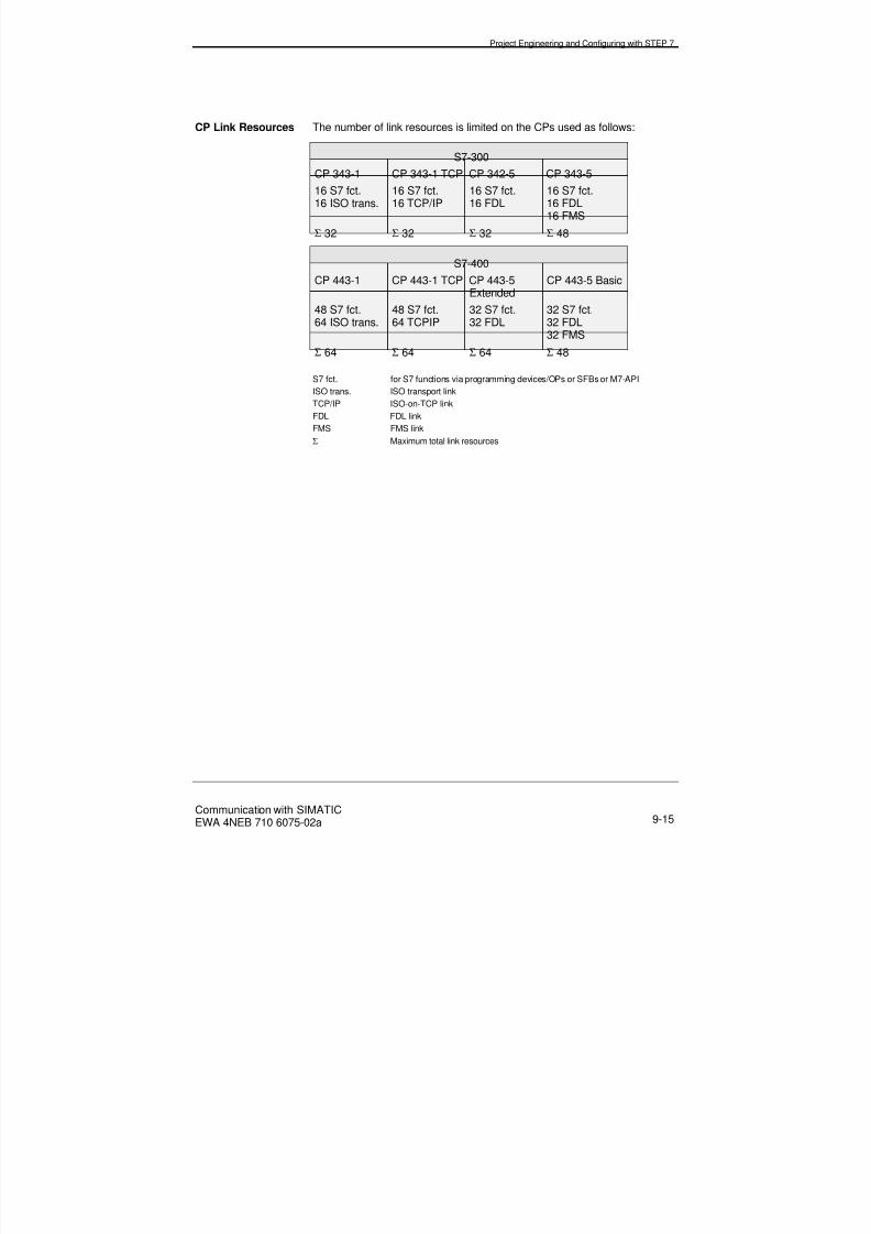
8/20/2019 Communication With Simatic Net
http://slidepdf.com/reader/full/communication-with-simatic-net 141/200
Project Engineering and Configuring with STEP 7
Communication with SIMATICEWA 4NEB 710 6075-02a 9-15
CP Link Resources The number of link resources is limited on the CPs used as follows:
S7-300
CP 343-1 CP 343-1 TCP CP 342-5 CP 343-5
16 S7 fct.16 ISO trans.
16 S7 fct.16 TCP/IP
16 S7 fct.16 FDL
16 S7 fct.16 FDL16 FMS
Σ 32 Σ 32 Σ 32 Σ 48
S7-400
CP 443-1 CP 443-1 TCP CP 443-5Extended
CP 443-5 Basic
48 S7 fct.64 ISO trans.
48 S7 fct.64 TCPIP
32 S7 fct.32 FDL
32 S7 fct.32 FDL
32 FMSΣ 64 Σ 64 Σ 64 Σ 48
S7 fct. for S7 functions via programming devices/OPs or SFBs or M7-APIISO trans. ISO transport linkTCP/IP ISO-on-TCP link
FDL FDL linkFMS FMS link
Σ Maximum total link resources

8/20/2019 Communication With Simatic Net
http://slidepdf.com/reader/full/communication-with-simatic-net 142/200
Project Engineering and Configuring with STEP 7
Communication with SIMATICEWA 4NEB 710 6075-02a9-16
9.5.1 Special Case of the Point-to-Point Link
Point-to-Point Link For a link between an S7-400 CPU and a communication partner that isconnected via a point-to-point link, the local CP 441 represents the cou-pling element. Conversion to the addressing mechanism of the selectedtransfer procedure takes place on the CP 441. The point-to-point linktherefore ends on the CP 441 and not on the communication partner as inthe case of the other link types.
The number of possible links to the CP 441 depends on the procedureused (1 link for 3964 (R), 1 to 4 links for RK 512).
The CP 441-2 has 2 physical interfaces, so up to 8 links can be config-ured to it.
Figure 9-13: Point-to-Point Link
CPU CP
Point-to-point link
Free link resource
Point-to-point link
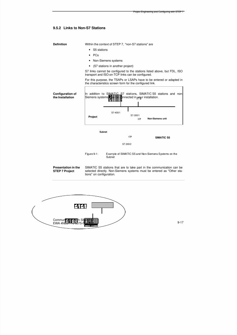
8/20/2019 Communication With Simatic Net
http://slidepdf.com/reader/full/communication-with-simatic-net 143/200
Project Engineering and Configuring with STEP 7
Communication with SIMATICEWA 4NEB 710 6075-02a 9-17
9.5.2 Links to Non-S7 Stations
Definition Within the context of STEP 7, "non-S7 stations" are• S5 stations
• PCs
• Non-Siemens systems
• (S7 stations in another project)
S7 links cannot be configured to the stations listed above, but FDL, ISOtransport and ISO-on-TCP links can be configured.
For this purpose, the TSAPs or LSAPs have to be entered or adapted inthe characteristics screen form for the configured link.
Configuration ofthe Installation
In addition to SIMATIC S7 stations, SIMATIC S5 stations and non-Siemens systems may be connected in your installation.
CP
CP
Subnet
Project
SIMATIC S5
Non-Siemens unit
S7-400/1S7-300/1
S7-300/2
Figure 9-1: Example of SIMATIC S5 and Non-Siemens Systems on theSubnet
Presentation in theSTEP 7 Project
SIMATIC S5 stations that are to take part in the communication can beselected directly. Non-Siemens systems must be entered as "Other sta-tions" on configuration.

8/20/2019 Communication With Simatic Net
http://slidepdf.com/reader/full/communication-with-simatic-net 144/200
Project Engineering and Configuring with STEP 7
Communication with SIMATICEWA 4NEB 710 6075-02a9-18
Notes

8/20/2019 Communication With Simatic Net
http://slidepdf.com/reader/full/communication-with-simatic-net 145/200
Programming Examples
Communication with SIMATICEWA 4NEB 710 6075-02a 10-1
10 Programming Examples
Overview In this Chapter, you will find the following communication examples:
Chapter Overview In Section You will find On page
10.1 Communication with SFCs 10-2
10.2 Communication with SFBs 10-4
10.3 Communication with FDL between SIMATIC S7s 10-7
10.4 Communication with FDL - SIMATIC S7 and S5 10-9
10.5 DP Communication via CPs 10-11
10.6 Communication with ISO Transport betweenSIMATIC S7s 10-12
10.7 Communication with ISO Transport -SIMATIC S7 and S5
10-14
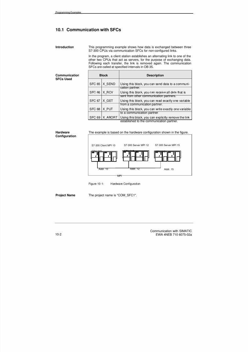
8/20/2019 Communication With Simatic Net
http://slidepdf.com/reader/full/communication-with-simatic-net 146/200
Programming Examples
Communication with SIMATICEWA 4NEB 710 6075-02a10-2
10.1 Communication with SFCs
Introduction This programming example shows how data is exchanged between threeS7-300 CPUs via communication SFCs for non-configured links.
In the program, a client station establishes an alternating link to one of theother two CPUs that act as servers, for the purpose of exchanging data.Following each transfer, the link is removed again. The communicationSFCs are called at specified intervals in OB 35.
CommunicationSFCs Used
Block Description
SFC 65 X_SEND Using this block, you can send data to a communi-cation partner.
SFC 66 X_RCV Using this block, you can receive all data that is
sent from other communication partners.SFC 67 X_GET Using this block, you can read exactly one variable
from a communication partner.
SFC 68 X_PUT Using this block, you can write exactly one variableto a communication partner.
SFC 69 X_ABORT Using this block, you can explicitly remove the linkestablished to the communication partner.
HardwareConfiguration
The example is based on the hardware configuration shown in the figure.
CPU 315 CPU 315
S7-300 Server MPI 12
MPI
Addr. 12Addr. 10 Addr. 15
CPU 315
S7-300 Client MPI 10 S7-300 Server MPI 15
Figure 10-1: Hardware Configuration
Project Name The project name is "COM_SFC1".

8/20/2019 Communication With Simatic Net
http://slidepdf.com/reader/full/communication-with-simatic-net 147/200
Programming Examples
Communication with SIMATICEWA 4NEB 710 6075-02a 10-3
Use Use the example program as follows:
• After a memory reset on each CPU, load the appropriate program inthe CPU.
• Execute a complete restart on each CPU.This causes initialization of the link references and the send and re-ceive areas.
• The send data is modified in the program so that you can see thedata transfer has been successful from the change in the receivedata.
• In the event of an error occurring during data transfer, evaluate theRET_VAL output parameter of the associated communication SFC.
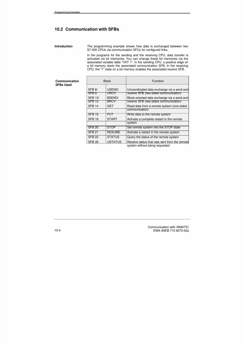
8/20/2019 Communication With Simatic Net
http://slidepdf.com/reader/full/communication-with-simatic-net 148/200
Programming Examples
Communication with SIMATICEWA 4NEB 710 6075-02a10-4
10.2 Communication with SFBs
Introduction The programming example shows how data is exchanged between twoS7-400 CPUs via communication SFCs for configured links.
In the programs for the sending and the receiving CPU, data transfer isactivated via bit memories. You can change these bit memories via theassociated variable table "VAT 1". In the sending CPU, a positive edge ona bit memory starts the associated communication SFB. In the receivingCPU, the "1" state on a bit memory enables the associated receive SFB.
CommunicationSFBs Used
Block Function
SFB 8/
SFB 9
USEND/
URCV
Uncoordinated data exchange via a send and
receive SFB (two-sided communication)SFB 12/ SFB 13
BSEND/ BRCV
Block-oriented data exchange via a send andreceive SFB (two-sided communication)
SFB 14 GET Read data from a remote system (one-sidedcommunication)
SFB 15 PUT Write data to the remote system
SFB 19 START Activate a complete restart in the remotesystem
SFB 20 STOP Set remote system into the STOP state
SFB 21 RESUME Activate a restart in the remote system
SFB 22 STATUS Query the status of the remote system
SFB 23 USTATUS Receive status that was sent from the remotesystem without being requested

8/20/2019 Communication With Simatic Net
http://slidepdf.com/reader/full/communication-with-simatic-net 149/200
Programming Examples
Communication with SIMATICEWA 4NEB 710 6075-02a 10-5
Bit memoriesUsed
Bit Memory Meaning
M 20.0 Activate USEND
M 20.1 Enable for URCV
M 20.2 Activate BSENDM 20.3 Enable for BRCV
M 20.4 Activate GET
M 20.5 Activate PUT
M 20.6 Activate START
M 20.7 Activate STOP
M 21.0 Activate RESUME
M 21.1 Activate STATUS
M 21.2 Activate USTATUS
Link Type A configured S7 link is used in this example. All blocks operate via thislink.
On both CPUs, the link ID number is W#16#0001.
HardwareConfiguration
The example is based on the hardware configuration shown in the figure.
SIMATIC-400 SEND SIMATIC-400 RCV
MPI
CPU 416-1 CPU 414-1
Addr. 12Addr. 9
Figure 10-2: Hardware Configuration
Project Name The project name is "COM_SFB".

8/20/2019 Communication With Simatic Net
http://slidepdf.com/reader/full/communication-with-simatic-net 150/200
Programming Examples
Communication with SIMATICEWA 4NEB 710 6075-02a10-6
Use Use the example program as follows:
• After a memory reset on each CPU, load the appropriate program inthe CPU.
• Execute a complete restart on each CPU.This causes initialization of the link references and the send and re-ceive areas. The send areas are preset with the number of the as-sociated SFBs and the receive areas are preset with "0".
• Call up the variable tables "VAT 1" (on the sending CPU) and "VAT2" (on the receiving CPU).
• Enable the receive SFBs on the receiving CPU by setting the appro-priate bit memories (M20.1 and M20.3) to "1" in the "VAT 2" variabletable.
• Start data transfer on the sending CPU by setting the appropriate bit
memories (M20.0, M20.2 and M20.4 to M21.2) to "1" in the "VAT 1"variable table.
• Change the contents of the send areas, as required.
• In the event of an error occurring during data transfer, evaluate theERROR and STATUS output parameters of the associated commu-nication SFB.
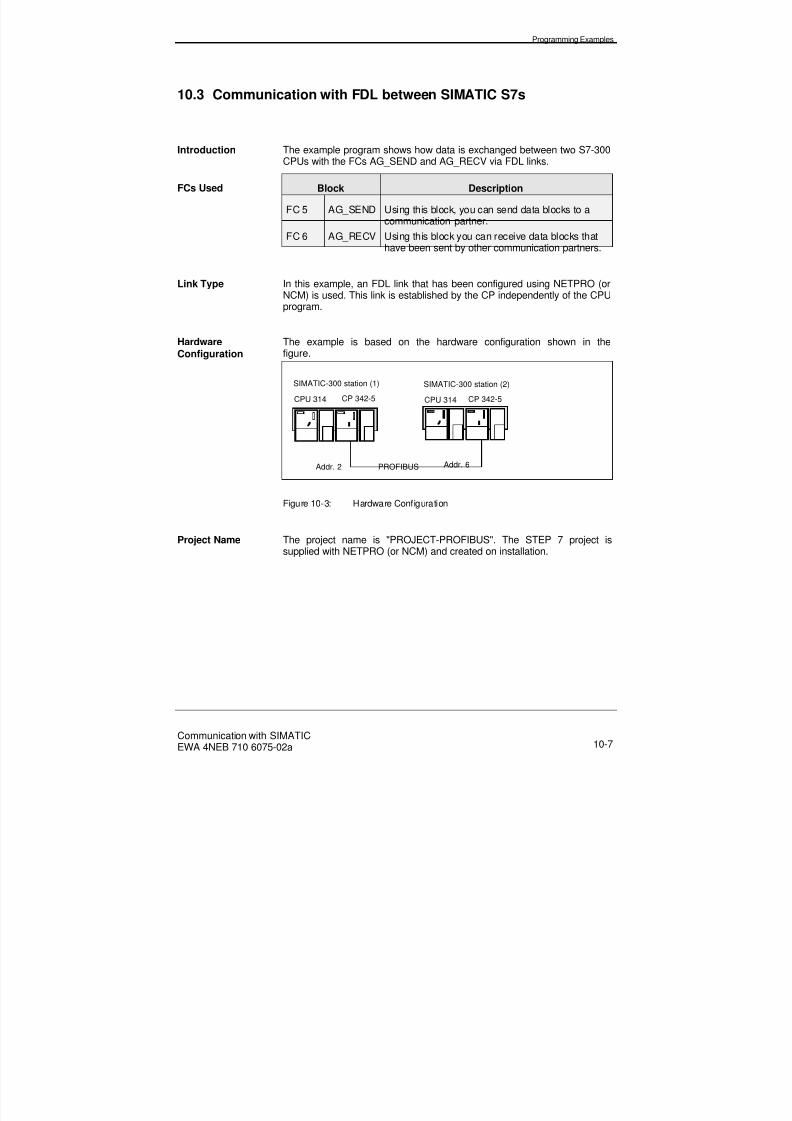
8/20/2019 Communication With Simatic Net
http://slidepdf.com/reader/full/communication-with-simatic-net 151/200
Programming Examples
Communication with SIMATICEWA 4NEB 710 6075-02a 10-7
10.3 Communication with FDL between SIMATIC S7s
Introduction The example program shows how data is exchanged between two S7-300CPUs with the FCs AG_SEND and AG_RECV via FDL links.
FCs Used Block Description
FC 5 AG_SEND Using this block, you can send data blocks to acommunication partner.
FC 6 AG_RECV Using this block you can receive data blocks thathave been sent by other communication partners.
Link Type In this example, an FDL link that has been configured using NETPRO (orNCM) is used. This link is established by the CP independently of the CPUprogram.
HardwareConfiguration
The example is based on the hardware configuration shown in thefigure.
SIMATIC-300 station (1) SIMATIC-300 station (2)
PROFIBUS
CPU 314 CPU 314
Addr. 6Addr. 2
CP 342-5 CP 342-5
Figure 10-3: Hardware Configuration
Project Name The project name is "PROJECT-PROFIBUS". The STEP 7 project issupplied with NETPRO (or NCM) and created on installation.

8/20/2019 Communication With Simatic Net
http://slidepdf.com/reader/full/communication-with-simatic-net 152/200
Programming Examples
Communication with SIMATICEWA 4NEB 710 6075-02a10-8
Use The use of this example program is described in the document "NCM S7for PROFIBUS". It describes the following steps in detail:
• Creating/opening the project
• Configuring and interconnecting the hardware
• Configuring the communication service
• Creating the user program
• Start-up and diagnostics
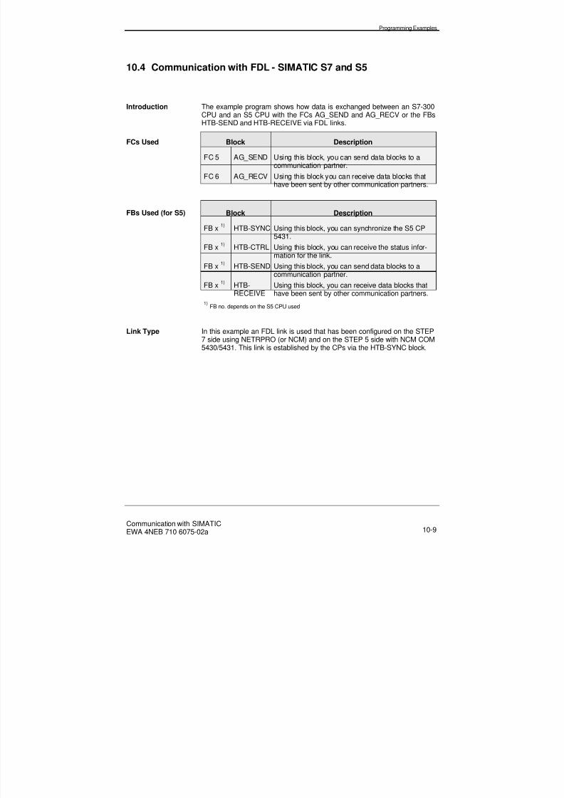
8/20/2019 Communication With Simatic Net
http://slidepdf.com/reader/full/communication-with-simatic-net 153/200
Programming Examples
Communication with SIMATICEWA 4NEB 710 6075-02a 10-9
10.4 Communication with FDL - SIMATIC S7 and S5
Introduction The example program shows how data is exchanged between an S7-300CPU and an S5 CPU with the FCs AG_SEND and AG_RECV or the FBsHTB-SEND and HTB-RECEIVE via FDL links.
FCs Used Block Description
FC 5 AG_SEND Using this block, you can send data blocks to acommunication partner.
FC 6 AG_RECV Using this block you can receive data blocks thathave been sent by other communication partners.
FBs Used (for S5) Block Description
FB x 1) HTB-SYNC Using this block, you can synchronize the S5 CP5431.
FB x 1) HTB-CTRL Using this block, you can receive the status infor-mation for the link.
FB x 1) HTB-SEND Using this block, you can send data blocks to acommunication partner.
FB x 1) HTB-RECEIVE
Using this block, you can receive data blocks thathave been sent by other communication partners.
1) FB no. depends on the S5 CPU used
Link Type In this example an FDL link is used that has been configured on the STEP7 side using NETRPRO (or NCM) and on the STEP 5 side with NCM COM5430/5431. This link is established by the CPs via the HTB-SYNC block.

8/20/2019 Communication With Simatic Net
http://slidepdf.com/reader/full/communication-with-simatic-net 154/200
Programming Examples
Communication with SIMATICEWA 4NEB 710 6075-02a10-10
HardwareConfiguration
The example is based on the hardware configuration shown in thefigure.
SIMATIC-300 station (3) SIMATIC S5 (1)
PROFIBUS
CPU 314 CPU x
Addr. 4Addr. 8
CP 342-5 CP 5431
Figure 10-4: Hardware Configuration
Directory andProject Name
The code for the STEP 7 example program can be found in the directory"step7\examples\profibus".
The project name is "PROFIBUS". The STEP 7 project is supplied withNETPRO (or NCM) and created on installation.
The STEP 5 sections of the example program are supplied with NCMCOM 5430/5431.
Link Type A link that does not require configuring is used in this example. This link isestablished and removed dynamically by the program.
Use The STEP 7 side of this example program is described in the document"NCM S7 for PROFIBUS". It describes the following steps in detail:
• Creating/opening the project
• Configuring and interconnecting the hardware
• Configuring the communication service
• Creating the user program
• Start-up and diagnostics

8/20/2019 Communication With Simatic Net
http://slidepdf.com/reader/full/communication-with-simatic-net 155/200
Programming Examples
Communication with SIMATICEWA 4NEB 710 6075-02a 10-11
10.5 DP Communication via CPs
Introduction The example program shows how data is exchanged between two S7-300CPUs via PROFIBUS-DP.
FCs Used Block Description
FC 1 DP_SEND Using this block, you can send data areas to acommunication partner.
FC 2 DP_RECV Using this block, you can receive data areas thathave been sent by another communication partner.
HardwareConfiguration
The example is based on the hardware configuration shown in the figure.
SIMATIC-300 DP master SIMATIC-300 DP slave
PROFIBUS
CPU 314 CPU 314
Addr. 12Addr. 10
CP 342-5 CP 342-5
Figure 10-5: Hardware Configuration
Project Name The project name is "PROFIBUS". The STEP 7 project is supplied withNETPRO (or NCM) and created on installation.
Use The use of this example program is described in the document "NCM S7for PROFIBUS". It describes the following steps in detail:
• Creating/opening the project
• Configuring and interconnecting the hardware
• Configuring the communication service
•
Creating the user program• Start-up and diagnostics
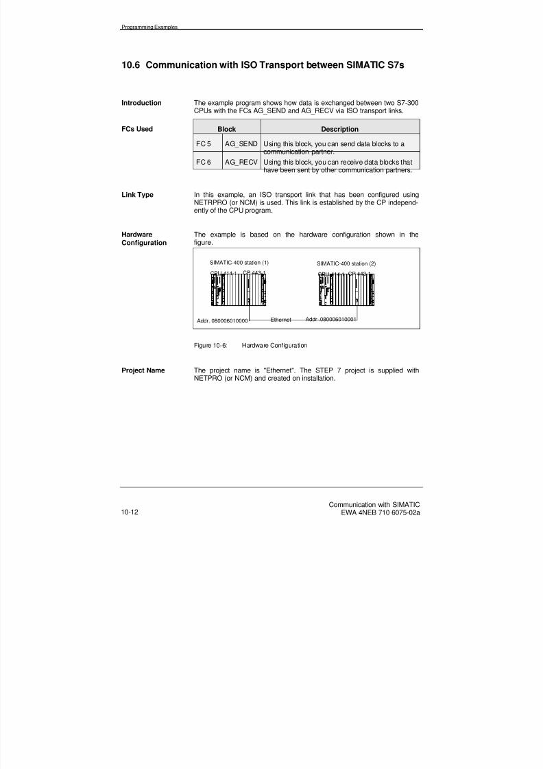
8/20/2019 Communication With Simatic Net
http://slidepdf.com/reader/full/communication-with-simatic-net 156/200
Programming Examples
Communication with SIMATICEWA 4NEB 710 6075-02a10-12
10.6 Communication with ISO Transport between SIMATIC S7s
Introduction The example program shows how data is exchanged between two S7-300CPUs with the FCs AG_SEND and AG_RECV via ISO transport links.
FCs Used Block Description
FC 5 AG_SEND Using this block, you can send data blocks to acommunication partner.
FC 6 AG_RECV Using this block, you can receive data blocks thathave been sent by other communication partners.
Link Type In this example, an ISO transport link that has been configured usingNETRPRO (or NCM) is used. This link is established by the CP independ-ently of the CPU program.
HardwareConfiguration
The example is based on the hardware configuration shown in thefigure.
SIMATIC-400 station (2)
EthernetAddr. 080006010000
SIMATIC-400 station (1)
CPU 414-1 CP 443-1 CPU 414-1
Addr .080006010001
CP 443-1
Figure 10-6: Hardware Configuration
Project Name The project name is "Ethernet". The STEP 7 project is supplied withNETPRO (or NCM) and created on installation.

8/20/2019 Communication With Simatic Net
http://slidepdf.com/reader/full/communication-with-simatic-net 157/200
Programming Examples
Communication with SIMATICEWA 4NEB 710 6075-02a 10-13
Use The use of this example program is described in the document "NCM S7for Industrial Ethernet". It describes the following steps in detail:
• Creating/opening the project
• Configuring and interconnecting the hardware
• Configuring the communication service
• Creating the user program
• Start-up and diagnostics

8/20/2019 Communication With Simatic Net
http://slidepdf.com/reader/full/communication-with-simatic-net 158/200
Programming Examples
Communication with SIMATICEWA 4NEB 710 6075-02a10-14
10.7 Communication with ISO Transport - SIMATIC S7 and S5
Introduction The example program shows how data is exchanged between an S7-400CPU and an S5 CPU with the FCs AG_SEND and AG_RECV or the FBsHTB-SEND and HTB-RECEIVE via ISO transport links.
FCs Used Block Description
FC 5 AG_SEND Using this block, you can send data blocks to acommunication partner.
FC 6 AG_RECV Using this block, you can receive data blocks thathave been sent by another communication partner.
FBs Used (for S5) Block Description
FB x 1) HTB-SYNC Using this block, you can synchronize the S5 CP5431.
FB x 1) HTB-CTRL Using this block, you can receive the status infor-mation for the link.
FB x 1) HTB-SEND Using this block, you can send data blocks to acommunication partner.
FB x 1) HTB-RECEIVE
Using this block, you can receive data blocks thathave been sent by another communication partner.
1) FB no. depends on the S5 CPU used
Link Type In this example, an ISO transport link is used that has been configured onthe STEP 7 side using NETRPRO (or NCM) and on the STEP 5 side withNCM COM 1430 TF. This link is established by the CPs following an error-free call of the HTB-SYNC block.

8/20/2019 Communication With Simatic Net
http://slidepdf.com/reader/full/communication-with-simatic-net 159/200
Programming Examples
Communication with SIMATICEWA 4NEB 710 6075-02a 10-15
HardwareConfiguration
The example is based on the hardware configuration shown in the figure.
EthernetAddr. 080006010003
SIMATIC-400 station (3)
CPU 414-1 CP 443-2SIMATIC S5 (1)CPU x
Addr. 080006010002
CP 1430 TF
Figure 10-7: Hardware Configuration
Project Name The project name is "Ethernet". The STEP 7 project is supplied withNETPRO (or NCM) and created on installation.
The STEP 5 sections of the example program are supplied with NCMCOM 1430 TF.
Use The use of this example program is described in the document "NCM S7for Industrial Ethernet". It describes the following steps in detail:
• Creating/opening the project
• Configuring and interconnecting the hardware
• Configuring the communication service
• Creating the user program
• Start-up and diagnostics

8/20/2019 Communication With Simatic Net
http://slidepdf.com/reader/full/communication-with-simatic-net 160/200
Programming Examples
Communication with SIMATICEWA 4NEB 710 6075-02a10-16
Notes

8/20/2019 Communication With Simatic Net
http://slidepdf.com/reader/full/communication-with-simatic-net 161/200
Appendix
Communication with SIMATICEWA 4NEB 710 6075-02a
A-1
A Appendix
Chapter Overview In Section You will find On page
A.1 Communications Matrix A-2
A.2 Technical Data A-12
A.3 Performance Data A-19
Glossary A-29

8/20/2019 Communication With Simatic Net
http://slidepdf.com/reader/full/communication-with-simatic-net 162/200
Communication with SIMATICEWA 4NEB 710 6075-02a
A-2
A.1 Communications Matrix
Definition Stations are categorized as follows:
Station (T) A station is able to communicate with another sta-tion in both directions (global data communication,GD).
Client (C) A client presents a communications task to theserver.
Server (S) A server executes a task presented by the client.
For communication to take place in accordance with the client/serverprinciple, one communications partner must be the client and the othermust be the server. This means that communication is not possible be-tween two servers or two clients.
From the following tables, it is possible to determine how the automationsystems are able to communicate with one another. The communicationcharacteristics are listed for each component:
• Subnet
• Services
• Communications partner
This information can be used to determine whether two communicationspartners are able to communicate with one another. Two communicationspartners can communicate with each other when all the following condi-tions are met:
• The "subnets" are identical
• The "services" are identical
• The communications partners form a pair, e.g. one is "client" and theother "server", i.e. the communications rules listed above are satis-fied.
Note Only those communications possibilities have been listed that have al-ready been implemented in the S7-200, S7/M7-300/400 systems.

8/20/2019 Communication With Simatic Net
http://slidepdf.com/reader/full/communication-with-simatic-net 163/200
Appendix
Communication with SIMATICEWA 4NEB 710 6075-02a
A.1.1 MPI Subnet
MPI Subnet
Communication Machine-Readable S7 Functions Global
Partner Product Designation (MLFB) SFBs SFCs HMI DataS7-200
CPU 215 6ES7 215-2AD00-0XB0 S1) S2) S -via DP interface 6ES7 215-2BD00-0XB0 S1) S2) S -S7-300
CPU 312 IFM 6ES7 312-5AC00-0AB0 - - S TCPU 313 6ES7 313-1AD00-0AB0 S1) - S T
6ES7 313-1AD01-0AB0 S1) C/S S TCPU 314 6ES7 314-1AE00-0AB0 S1) - S T
6ES7 314-1AE01-0AB0 S1) - S T6ES7 314-1AE02-0AB0 S1) C/S S T
CPU 314 IFM 6ES7 314-5AE00-0AB0 S1) - S T6ES7 314-5AE01-0AB0 S1) C/S S T
CPU 315 6ES7 315-1AF00-0AB0 S1) - S T6ES7 315-1AF01-0AB0 S1) C/S S T
CPU 315-2 DP 6ES7 315-2AF00-0AB0 S1)
- S T6ES7 315-2AF01-0AB0 S1) C/S S TFM 353 6ES7 353-1AH00-0AE0 - - S -
6ES7 353-1AH01-0AE0 - - S -FM 354 6ES7 354-1AH00-0AE0 - - S -
6ES7 354-1AH01-0AE0 - - S -FM 355 C 6ES7 355-0VH00-0AE0 - S2) - -
6ES7 355-0VH10-0AE0 - - S -FM 355 S 6ES7 355-1VH00-0AE0 - S2) - -
6ES7 355-1VH10-0AE0 - - S -M7-300
FM 356-4 6ES7 356-4BN00-0AE0 C/S C/S C/S -6ES7 356-4BM00-0AE0 C/S C/S C/S -
CPU 388-4 6ES7 388-4BN00-0AC0 C/S C/S C/S -
1) Only with GET/PUT functions (SFB block is not required in user program)!2) Only with I-GET/I-PUT functions!

8/20/2019 Communication With Simatic Net
http://slidepdf.com/reader/full/communication-with-simatic-net 164/200
CA-4
MPI Subnet
Communication Machine-Readable S7 Functions Global
Partner Product Designation (MLFB) SFBs SFCs HMI Data
S7-400
CPU 412-1 6ES7 412-1XF00-0AB0 C/S - S T
6ES7 412-1XF01-0AB0 C/S C/S S TCPU 413-1 6ES7 413-1XG00-0AB0 C/S - S T6ES7 413-1XG01-0AB0 C/S C/S S T
CPU 413-2DP 6ES7 413-2XG00-0AB0 C/S - S T6ES7 413-2XG01-0AB0 C/S C/S S T
CPU 414-1 6ES7 414-1XG00-0AB0 C/S - S T6ES7 414-1XG01-0AB0 C/S C/S S T
CPU 414-2DP 6ES7 414-2XG00-0AB0 C/S - S T6ES7 414-2XG01-0AB0 C/S C/S S T6ES7 414-2XJ00-0AB0 C/S C/S S T
CPU 416-1 6ES7 416-1XJ00-0AB0 C/S - S T6ES7 416-1XJ01-0AB0 C/S C/S S T
CPU 416-2DP 6ES7 416-2XK00-0AB0 C/S C/S S T6ES7 416-2XL00-0AB0 C/S C/S S T
M7-400
CPU 486-3 6ES7 486-3AA00-0AB0 C/S C/S C/S -CPU 488-3 6ES7 488-3AA00-0AB0 C/S C/S C/S -FM 456-4 6ES7 456-4EY00-0AE0 C/S C/S C/S -C7-620
C7 621 6ES7 621-1AD00-0AE3 S - C/S TC7 623 6ES7 623-1AE00-0AE3 S - C/S TC7 623 a 6ES7 623-1CE00-0AE3 S - C/S TC7 624 6ES7 624-1AE00-0AE3 S - C/S TC7 626 6ES7 626-1AG00-0AE3 S - C/S TC7 626 a 6ES7 626-1CG00-0AE3 S - C/S TC7 626 DP 6ES7 626-2AG00-0AE3 S - C/S TOPs (with ProTool V 3.x)
OP 7/DP 6AV3 607-1JC20-0XA0 - - C -OP 7/DP-12 6AV3 607-1JC30-0XA0 - - C -OP 17/DP 6AV3 617 1JC20-0XA0 - - C -OP 17/DP-12 6AV3 617 1JC30-0XA0 - - C -OP 25 6AV3 525-1EA.1-0AX0 - - C -OP 35 6AV3 535-1FA01-0AX0 - - C -OP 37 6AV3 637-1 .L00-0 . X0 - - C -OPs (with ProTool < V 3.x)
OP 3 6AV3 503-1DB10 - - - -OP 5/A2 6AV3 505-1FB12 - - C 3) -OP 15/A2 6AV3 515-1EB32-1AA0 - - C 3) -
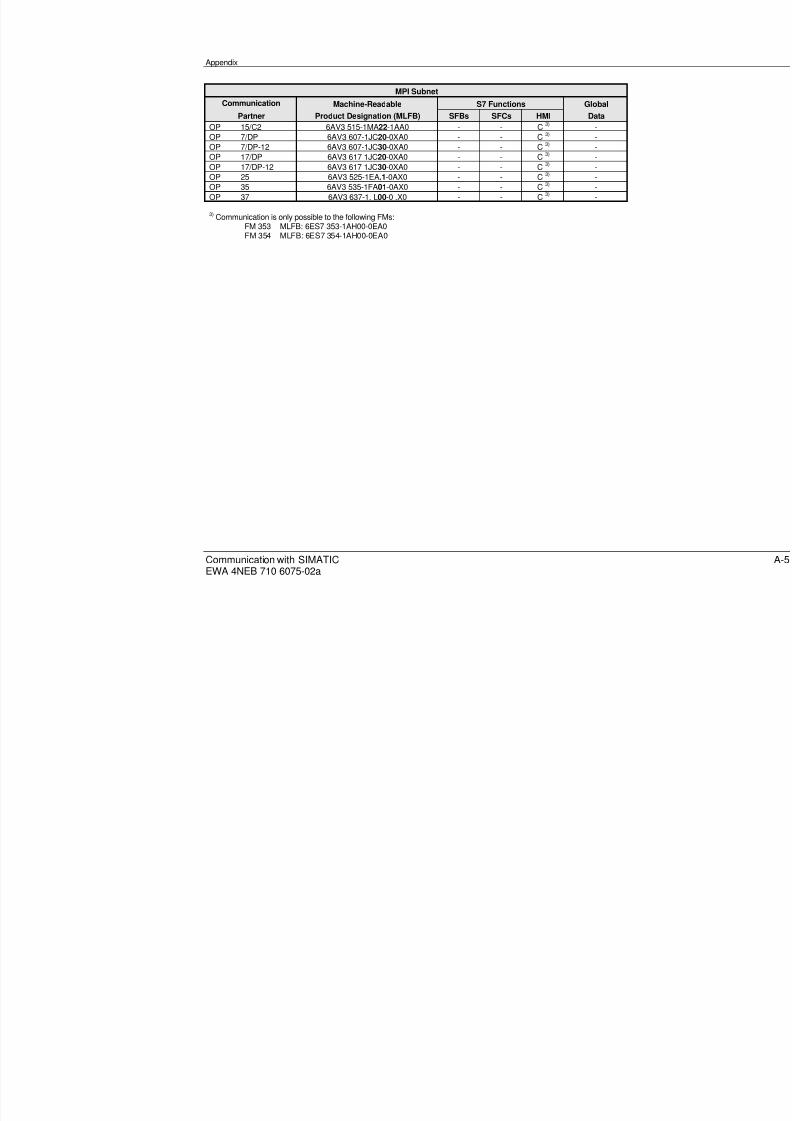
8/20/2019 Communication With Simatic Net
http://slidepdf.com/reader/full/communication-with-simatic-net 165/200
Appendix
Communication with SIMATICEWA 4NEB 710 6075-02a
MPI Subnet
Communication Machine-Readable S7 Functions Global
Partner Product Designation (MLFB) SFBs SFCs HMI Data
OP 15/C2 6AV3 515-1MA22-1AA0 - - C 3) -OP 7/DP 6AV3 607-1JC20-0XA0 - - C 3) -
OP 7/DP-12 6AV3 607-1JC30-0XA0 - - C
3)
-OP 17/DP 6AV3 617 1JC20-0XA0 - - C 3) -OP 17/DP-12 6AV3 617 1JC30-0XA0 - - C 3) -OP 25 6AV3 525-1EA.1-0AX0 - - C 3) -OP 35 6AV3 535-1FA01-0AX0 - - C 3) -OP 37 6AV3 637-1. L00-0 .X0 - - C 3) -
3) Communication is only possible to the following FMs:FM 353 MLFB: 6ES7 353-1AH00-0EA0FM 354 MLFB: 6ES7 354-1AH00-0EA0

8/20/2019 Communication With Simatic Net
http://slidepdf.com/reader/full/communication-with-simatic-net 166/200
CA-6
A.1.2 PROFIBUS Subnet
PROFIBUS Subnet
Communication Machine-Readable Via Integral PROFIBUS-DP Via PR
Partner Product Designation S7 Functions S7 Functions(MLFB) SFBs I-SFCs HMI
1)SFBs HMI
S7-200
CPU 215 6ES7 215-2AD00-0XB0 - - S - -6ES7 215-2BD00-0XB0 - - S - -
S7-300
CPU 312 IFM 6ES7 312-5AC00-0AB0 - - -CPU 313 6ES7 313-1AD00-0AB0 - - -
6ES7 313-1AD01-0AB0 - - -CPU 314 6ES7 314-1AE00-0AB0 - - -
6ES7 314-1AE01-0AB0 - - -6ES7 314-1AE02-0AB0 - - -
CPU 314 IFM 6ES7 314-5AE00-0AB0 - - -6ES7 314-5AE01-0AB0 - - - S via
CPU 315 6ES7 315-1AF00-0AB0 - - - CP 342-5
6ES7 315-1AF01-0AB0 - - - orCPU 315-2 DP 6ES7 315-2AF00-0AB0 - - - CP 343-5
6ES7 315-2AF01-0AB0 - C2) /S SFM 353 6ES7 353-1AH00-0AE0 - - S
6ES7 353-1AH01-0AE0 - - S - 3)
FM 354 6ES7 354-1AH00-0AE0 - - S6ES7 354-1AH01-0AE0 - - S - 3)
FM 355 C 6ES7 355-0VH00-0AE0 - - - -6ES7 355-0VH10-0AE0 - S 4) S -
FM 355 S 6ES7 355-1VH00-0AE0 - - - -6ES7 355-1VH10-0AE0 - S 4) S -
M7-300
CPU 388-4 6ES7 388-4BN00-0AC0 - C SFM 356-4 6ES7 356-4BM00-0AE0 - - S C/S via CP 342-5
6ES7 356-4BN00-0AE0 - C S or CP 343-51)
S7 functions2) Communication with distributed FMs 353/354/355 is possible with product release 03 and later3) Not possible via CP 342-5 or CP 343-5!4) Decentralized communication in an ET 200M is possible with IM 153-2
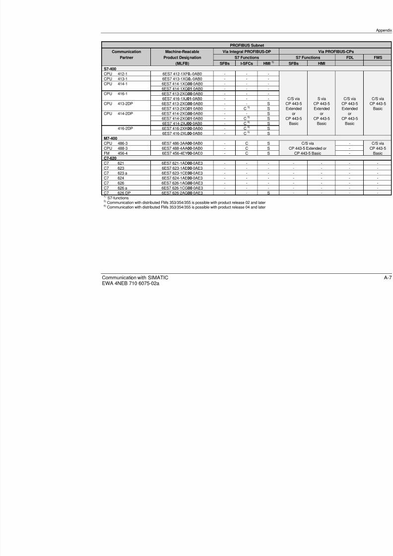
8/20/2019 Communication With Simatic Net
http://slidepdf.com/reader/full/communication-with-simatic-net 167/200
Communication with SIMATICEWA 4NEB 710 6075-02a
PROFIBUS Subnet
Communication Machine-Readable Via Integral PROFIBUS-DP Via PR
Partner Product Designation S7 Functions S7 Functions
(MLFB) SFBs I-SFCs HMI1)
SFBs HMI
S7-400
CPU 412-1 6ES7 412-1XF0.-0AB0 - - -CPU 413-1 6ES7 413-1XG0.-0AB0 - - -CPU 414-1 6ES7 414-1XG00-0AB0 - - -
6ES7 414-1XG01-0AB0 - - -CPU 416-1 6ES7 413-2XG00-0AB0 - - -
6ES7 416-1XJ01-0AB0 - - - C/S via S viaCPU 413-2DP 6ES7 413-2XG00-0AB0 - - S CP 443-5 CP 443-5
6ES7 413-2XG01-0AB0 - C 5) S Extended ExtendedCPU 414-2DP 6ES7 414-2XG00-0AB0 - - S or or
6ES7 414-2XG01-0AB0 - C 5) S CP 443-5 CP 443-56ES7 414-2XJ00-0AB0 - C 6) S Basic Basic
416-2DP 6ES7 416-2XK00-0AB0 - C 6) S6ES7 416-2XL00-0AB0 - C 6) S
M7-400
CPU 486-3 6ES7 486-3AA00-0AB0 - C S C/S via
CPU 488-3 6ES7 488-4AA00-0AB0 - C S CP 443-5 Extended orFM 456-4 6ES7 456-4EY00-0AE0 - C S CP 443-5 BasicC7-620
C7 621 6ES7 621-1AD00-0AE3 - - - - -C7 623 6ES7 623-1AE00-0AE3 - - - - -C7 623 a 6ES7 623-1CE00-0AE3 - - - - -C7 624 6ES7 624-1AE00-0AE3 - - - - -C7 626 6ES7 626-1AG00-0AE3 - - - - -C7 626 a 6ES7 626-1CG00-0AE3 - - - - -C7 626 DP 6ES7 626-2AG00-0AE3 - - S - -1) S7-functions5) Communication with distributed FMs 353/354/355 is possible with product release 02 and later6) Communication with distributed FMs 353/354/355 is possible with product release 04 and later
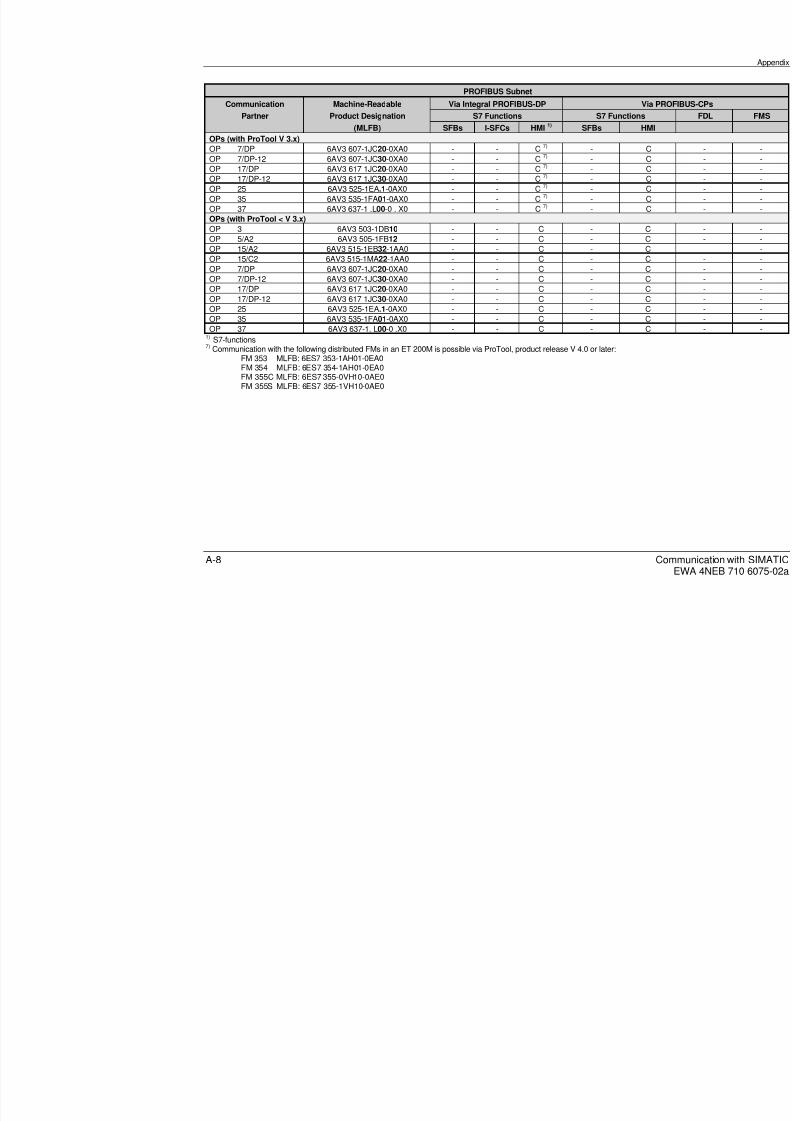
8/20/2019 Communication With Simatic Net
http://slidepdf.com/reader/full/communication-with-simatic-net 168/200
CA-8
PROFIBUS Subnet
Communication Machine-Readable Via Integral PROFIBUS-DP Via PR
Partner Product Designation S7 Functions S7 Functions
(MLFB) SFBs I-SFCs HMI1)
SFBs HMI
OPs (with ProTool V 3.x)
OP 7/DP 6AV3 607-1JC20-0XA0 - - C7)
- COP 7/DP-12 6AV3 607-1JC30-0XA0 - - C 7) - COP 17/DP 6AV3 617 1JC20-0XA0 - - C 7) - COP 17/DP-12 6AV3 617 1JC30-0XA0 - - C 7) - COP 25 6AV3 525-1EA.1-0AX0 - - C 7) - COP 35 6AV3 535-1FA01-0AX0 - - C 7) - COP 37 6AV3 637-1 .L00-0 . X0 - - C 7) - COPs (with ProTool < V 3.x)
OP 3 6AV3 503-1DB10 - - C - COP 5/A2 6AV3 505-1FB12 - - C - COP 15/A2 6AV3 515-1EB32-1AA0 - - C - COP 15/C2 6AV3 515-1MA22-1AA0 - - C - COP 7/DP 6AV3 607-1JC20-0XA0 - - C - COP 7/DP-12 6AV3 607-1JC30-0XA0 - - C - COP 17/DP 6AV3 617 1JC20-0XA0 - - C - C
OP 17/DP-12 6AV3 617 1JC30-0XA0 - - C - COP 25 6AV3 525-1EA.1-0AX0 - - C - COP 35 6AV3 535-1FA01-0AX0 - - C - COP 37 6AV3 637-1. L00-0 .X0 - - C - C
1) S7-functions7) Communication with the following distributed FMs in an ET 200M is possible via ProTool, product release V 4.0 or later:
FM 353 MLFB: 6ES7 353-1AH01-0EA0FM 354 MLFB: 6ES7 354-1AH01-0EA0FM 355C MLFB: 6ES7 355-0VH10-0AE0FM 355S MLFB: 6ES7 355-1VH10-0AE0

8/20/2019 Communication With Simatic Net
http://slidepdf.com/reader/full/communication-with-simatic-net 169/200
Communication with SIMATICEWA 4NEB 710 6075-02a
A.1.3 Industrial Ethernet
Industrial Ethernet
Communication Machine-Readable S7 Functions ISO Transport
Partner Product Designation (MLFB) SFBs HMIS7-200
CPU 215 6ES7 215-2AD00-0XB0 - - -6ES7 215-2BD00-0XB0 - - -
S7-300
CPU 312 IFM 6ES7 312-5AC00-0AB0CPU 313 6ES7 313-1AD00-0AB0
6ES7 313-1AD01-0AB0CPU 314 6ES7 314-1AE00-0AB0
6ES7 314-1AE01-0AB06ES7 314-1AE02-0AB0
CPU 314 IFM 6ES7 314-5AE00-0AB0 S via S via C/S via6ES7 314-5AE01-0AB0 CP 343-1 CP 343-1 CP 343-1
CPU 315 6ES7 315-1AF00-0AB0 or6ES7 315-1AF01-0AB0 CP 343-1/TCP
CPU 315-2 DP 6ES7 315-2AF00-0AB06ES7 315-2AF01-0AB0FM 353 6ES7 353-1AH00-0AE0 -
6ES7 353-1AH01-0AE0 -FM 354 6ES7 354-1AH00-0AE0 -
6ES7 354-1AH01-0AE0 -FM 355 C 6ES7 355-0VH00-0AE0 -
6ES7 355-0VH10-0AE0 -FM 355 S 6ES7 355-1VH00-0AE0 -
6ES7 355-1VH10-0AE0 -M7-300
CPU 388-4 6ES7 388-4BN00-0CA0 C/S via C/S via -FM 356-4 6ES7 356-4BM00-0AE0 CP 343-1 or CP 343-1 -
6ES7 356-4BN00-0AE0 CP 343-1/TCP -

8/20/2019 Communication With Simatic Net
http://slidepdf.com/reader/full/communication-with-simatic-net 170/200
CA-10
Industrial Ethernet
Communication Machine-Readable S7 Functions ISO Transport
Partner Product Designation (MLFB) SFBs HMI
S7-400
CPU 412-1 6ES7 412-1XF0.-0AB0
CPU 413-1 6ES7 413-1XG0.-0AB0CPU 414-1 6ES7 414-1XG0.-0AB0CPU 416-1 6ES7 413-2XJ0.-0AB0 C/S via S via C/S viaCPU 413-2DP 6ES7 413-2XG0.-0AB0 CP 443-1 or CP 443-1 CP 443-1CPU 414-2DP 6ES7 414-2XG0.-0AB0 CP 443-1/TCP
6ES7 414-2XJ00-0AB0CPU 416-2DP 6ES7 416-2XK00-0AB0
6ES7 416-2XL00-0AB0M7-400
CPU 486-3 6ES7 486-3AA00-0AB0 C/S via C/S via -CPU 488-3 6ES7 488-3AA00-0AB0 CP 443-1 or CP 443-1 -FM 456-4 6ES7 456-4EY00-0AE0 CP 443-1/TCP -C7-620
C7 621 6ES7 621-1AD00-0AE3 - - -C7 623 6ES7 623-1AE00-0AE3 - - -C7 623 a 6ES7 623-1CE00-0AE3 - - -C7 624 6ES7 624-1AE00-0AE3 - - -C7 626 6ES7 626-1AG00-0AE3 - - -C7 626 a 6ES7 626-1CG00-0AE3 - - -C7 626 DP 6ES7 626-2AG00-0AE3 - - -OPs (with ProTool V 3.x)
OP 7/DP 6AV3 607-1JC20-0XA0 - - -OP 7/DP-12 6AV3 607-1JC30-0XA0 - - -OP 17/DP 6AV3 617 1JC20-0XA0 - - -OP 17/DP-12 6AV3 617 1JC30-0XA0 - - -OP 25 6AV3 525-1EA.1-0AX0 - - -OP 35 6AV3 535-1FA01-0AX0 - - -OP 37 6AV3 637-1 .L00-0 . X0 - - -OPs (with ProTool < V 3.x)
OP 3 6AV3 503-1DB10 - - -OP 5/A2 6AV3 505-1FB12 - - -OP 15/A2 6AV3 515-1EB32-1AA0 - - -OP 15/C2 6AV3 515-1MA22-1AA0 - - -OP 7/DP 6AV3 607-1JC20-0XA0 - - -OP 7/DP-12 6AV3 607-1JC30-0XA0 - - -OP 17/DP 6AV3 617 1JC20-0XA0 - - -OP 17/DP-12 6AV3 617 1JC30-0XA0 - - -OP 25 6AV3 525-1EA.1-0AX0 - - -
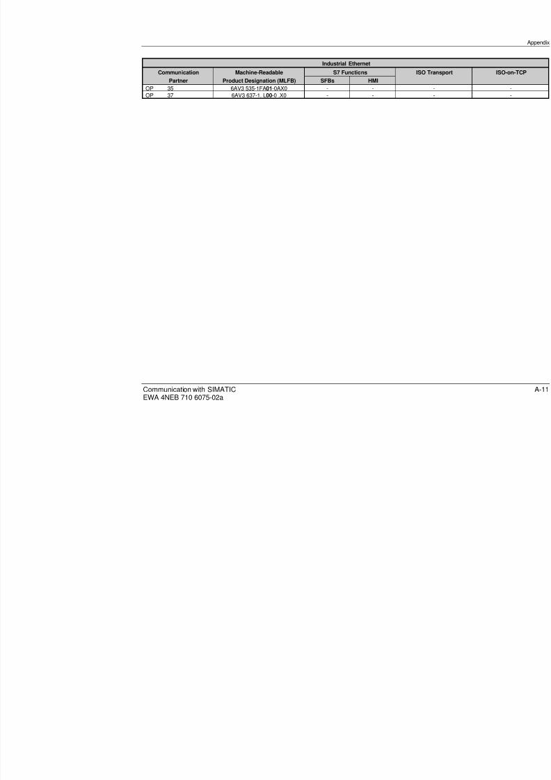
8/20/2019 Communication With Simatic Net
http://slidepdf.com/reader/full/communication-with-simatic-net 171/200
Communication with SIMATICEWA 4NEB 710 6075-02a
Industrial Ethernet
Communication Machine-Readable S7 Functions ISO Transport
Partner Product Designation (MLFB) SFBs HMI
OP 35 6AV3 535-1FA01-0AX0 - - -OP 37 6AV3 637-1. L00-0 .X0 - - -

8/20/2019 Communication With Simatic Net
http://slidepdf.com/reader/full/communication-with-simatic-net 172/200
CA-12
A.2 Technical Data
A.2.1 SIMATIC S7-200
Module Type CPU
Module CPU 212 CPU 214 CPU 215
InterfacesNetworkNumber
PPI1
PPI1
PPI2
P2
Technical dataInterfaceTransmission rate:S7 functionsASCIIPROFIBUS-DP
RS 485
9.6 Kbit/s300 bit/s to 19.2 Kbit/s-
RS 485
9.6 Kbit/s300 bit/s to 38.4 Kbit/s-
RS 485
9.6 Kbit/s or 19.2 Kbit/s300 bit/s to 38.4 Kbit/sup to 12 Mbit/s
R
93-
Communication servicesS7 functionsNumber of active linksNumber of stations
131 (127 with repeater)
831 (127 with repeater)
831 (127 with repeater)
83
ASCIINumber of active linksNumber of stations
Specified in user programSpecified in user program
Specified in user programSpecified in user program
Specified in user programSpecified in user program
SS
Services for simultane-ous execution
1 service/cycle 1 service/cycle 1 service/cycle 1
CPU loading PPI ASCII mode PPI ASCIImode
PPImaster
PPI ASCII mode PA
Extension of the userprogram cycle, approx.
< 1% Depends onuser program
< 1%Depends onuser pro-gram
-6%
< 1% Depends on userprogram
<Du
Extension of the inter-rupt response time,approx.
- - - - - - - -

8/20/2019 Communication With Simatic Net
http://slidepdf.com/reader/full/communication-with-simatic-net 173/200
Communication with SIMATICEWA 4NEB 710 6075-02a
A.2.2 SIMATIC S7-300
Module type CPU
Module CPU 312-IFM CPU 313 CPU 314/-IFM CPU 315 CP
Interfaces
NetworkNumber
MPI1
MPI1
MPI1
MPI1
MP1
Technical dataInterfaceTransmission rate
Galvanic isolation to LAN
RS 485187.5 Kbit/s
No
RS 485187.5 Kbit/s
No
RS 485187.5 Kbit/s
No
RS 485187.5 Kbit/s
No
RS187
No
Link resourcesS7 functions (incl. programming device/OP)Number of links max.Client/server
Communication via SFCsNumber of links max.
4Server
-
4Server
4
4Server
8
4Server
8
4Se
8
Global data (GD)Number of GD circlesUseful data in bytes/of which consistent
422/8
422/8
422/8
422/8
422/
DPNumber of slavesUseful data in bytes- per station/of which consistent- total
CPU loadingProgram cycle is lengthened in accordance withthe communication loading parameterizable by:Extension of interrupt response time 10 to 50%
-10 to 50%-
10 to 50%-
10 to 50%-
10 -

8/20/2019 Communication With Simatic Net
http://slidepdf.com/reader/full/communication-with-simatic-net 174/200
CA-14
Module Type CP
Module CP 343-1 CP 343-1 TCP CP 342-5 CP 343-5
InterfacesNetworkNumber
Industrial Ethernet1
Industrial Ethernet1
PROFIBUS1
PROFIBUS1
Technical data
InterfaceTransmission rateGalvanic isolation to LAN
AUI/ITP10 Mbit/sYes
AUI/ITP10 Mbit/sYes
RS 4859.6 Kbit/s to 1.5Mbit/sYes
RS 4859.6 Kbit/s to 1Yes
Number of links via all services 32 32 32 48Communications servicesS7 functions 1)
Max. no. of links 16 16 16 16SEND/RECEIVENumber of linksClient/ServerUseful data in bytes/of which consistent
16Client/Server240/240
16Client/Server240/240
16Client/Server240/240
16Client/Server240/240
FMSNumber of linksClient/Server
- - - 16Client/Server
DPNumber of slavesUseful data in bytes/of which consistent
- - 64240/240
-
CPU loadingExtension of user program cycle- Additional time for FB callExtension of interrupt response time- S7 functions- SEND/RECEIVE- FMS / DP
10 to 50%
NoYes-
10 to 50%
NoYes-
10 to 50%
NoYesYes
10 to 50%
NoYesYes
1)
The S7 functions are passed on from the LAN to the CPU and vice-versa. For a detailed list of services, see CPUs.

8/20/2019 Communication With Simatic Net
http://slidepdf.com/reader/full/communication-with-simatic-net 175/200
Communication with SIMATICEWA 4NEB 710 6075-02a
A.2.3 SIMATIC S7-400
Module Type CPU
Module CPU 412-1 CPU 413-1 CPU 413-2 DP CPU 414-1 CPU 414-2 DP C
Interfaces
NetworkNumber
MPI1
MPI1
MPI1
DP1
MPI1
MPI1
DP1
M1
Technical dataInterface RS 485 RS 485 RS485 RS485 RS 485 RS485 RS485 RTransmission rate 187.5 Kbit/s 187.5 Kbit/s 187.5
Kbit/s12 Mbit/s 187.5 Kbit/s 187.5
Kbit/s12Mbit/s
1
Galvanic isolation to LAN No No No Yes No No Yes NCommunication servicesS7 functions (incl. programmingdevice/OP)Client/ServerMax. no. of linksUseful data in bytes/of which consis-tent
C/S16480/32
C/S16480/32
C/S16480/32
C/S32480/32
C/S32 1)
480/32
C64
Global data (GD)
Number of GD circlesUseful data in bytes/of which consis-tent
854/32
854/32
854/32
854/32
854/32
15
DPNumber of slavesUseful data in bytes- per station/
of which consistent- total
- 64
122/ 1222 K
- 96
122/ 122 4 K
CPU loadingProgram cycle is lengthened in accor-dance with the communication loadingparameterizable by:Extension of interrupt response time
10 to 50%-
10 to 50%-
10 to 50%-
10 to 50%-
10 to 50%-
1-
1) A maximum of 16 S7 connections (e.g. OPs) can be realized via the internal DP interface of the CPU.2) A maximum of 44 S7 connections can be realized via the MPI interface of the CPU.

8/20/2019 Communication With Simatic Net
http://slidepdf.com/reader/full/communication-with-simatic-net 176/200
CA-16
Module Type CP
Module CP 443-1 CP 443-1 TCP CP 443-5 Basic CP 443-5 E
InterfacesNetworkNumber
Industrial Ethernet1
Industrial Ethernet1
PROFIBUS1
PROFIBUS1
Technical dataInterfaceTransmission rateGalvanic isolation to LAN
AUI/ITP10 Mbit/sYes
AUI/ITP10 Mbit/sYes
RS 4859.6 Kbit/s to 12 Mbit/sYes
RS 4859.6 Kbit/s toYes
Number of links via all serviceswithout PROFIBUS-DP
with PROFIBUS-DP
64 64 4859, no time58, time-of-55, no time54, time-of-
Communication servicesS7 functionsMax. no. of links 48 48 32 32
SEND/RECEIVEMax. no. of linksClient/Server
Useful data in bytes/of which consistent
64Client/Server
240/240
64Client/Server
240/240
32Client/Server
240/240
32Client/Serv
240/240
FMSMax. no. of linksClient/ServerUseful data in bytes/of which consistent
---
---
32Client/ServerClient 238/238Server 238/32
16Client/ServClient 238/Server 238
DPNumber of slavesUseful data in bytes- per station/of which consistent
- total
- - -125
244/ 2 or 4mands, 2404096
CPU loadingExtension of the user program cycle plus time
for conducting the communication:Extension of interrupt response time
10 to 50 %
parameterizableNo
10 to 50 %
parameterizableNo
10 to 50 %
parameterizableNo
10 to 50 %
parameterizNo

8/20/2019 Communication With Simatic Net
http://slidepdf.com/reader/full/communication-with-simatic-net 177/200
Communication with SIMATICEWA 4NEB 710 6075-02a
A.2.4 SIMATIC M7-300/400
Module Type CPU
Module CPU 388-4 CPU 488/486-3 FM 356-4
Interfaces
NetworkNumber
MPI1
DP1with IF 964-DP
MPI1
DP1withIF 964-DP
MPI1access viaCPU
DP1withIF 964-
Technical dataInterface RS485 RS485 RS485 RS485 RS485 RS485Transmission rate 187.5 Kbit/s 12 Mbit/s 187.5 Kbit/s 12 Mbit/s 187.5 Kbit/s 12 Mbit
Communication servicesS7 functions (incl. programming device/OP)Client/ServerMax. no. of linksUseful data in bytes max.
C/S64942
C/S64942
C/S64942
Communication via M7-API functionsMax. no. of links 56 56 56
Global data (GD)Number of GD circlesUseful data in bytes/of which consistent
- - -
DPNumber of slavesUseful data in bytes- per station/
of which consistent- total
- 96
122/ 1222 K
- 96
122/ 1224 K
- 96
122/ 122 2 K
CPU loadingExtension of the user program cycle plus timefor conducting the communication:Extension of interrupt response time
Notadjustable-
Notadjustable-
Notadjustable-

8/20/2019 Communication With Simatic Net
http://slidepdf.com/reader/full/communication-with-simatic-net 178/200
CA-18
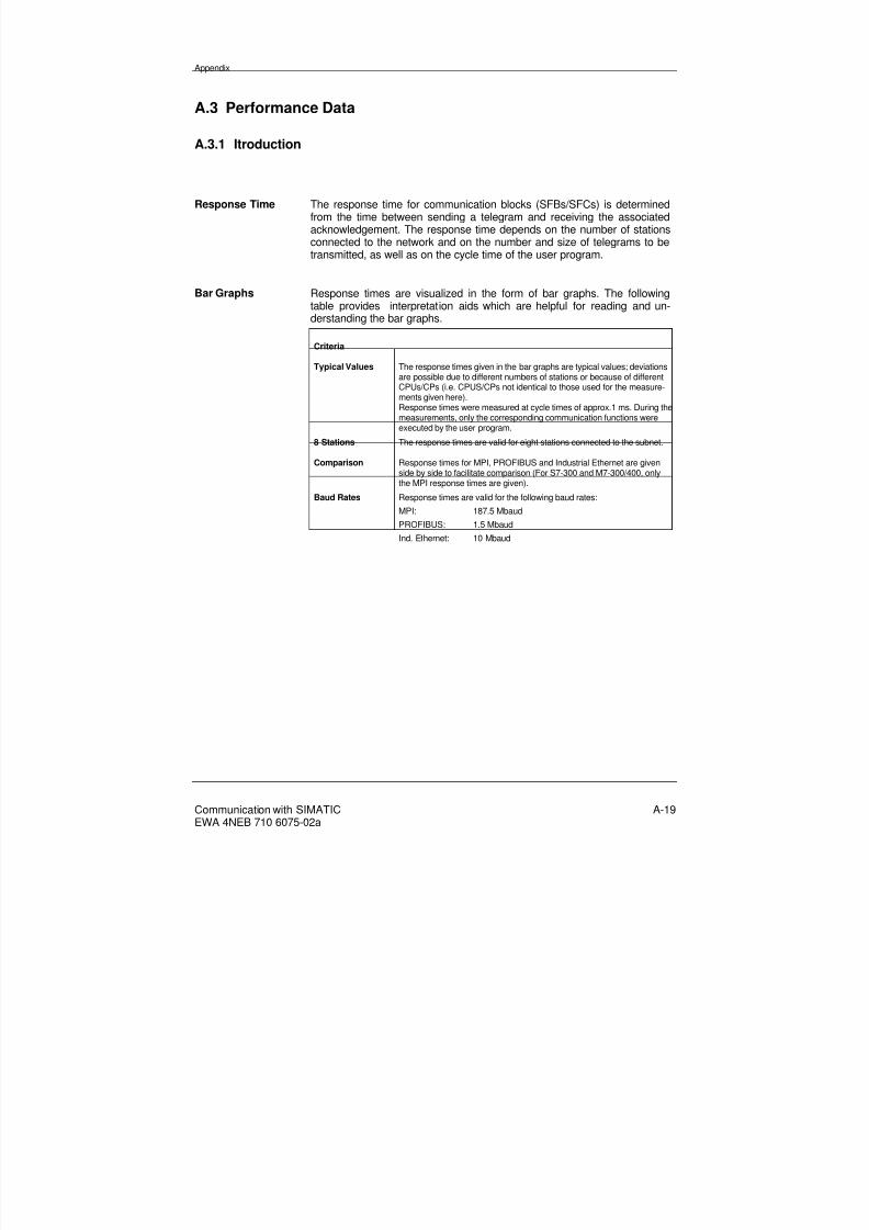
8/20/2019 Communication With Simatic Net
http://slidepdf.com/reader/full/communication-with-simatic-net 179/200
Appendix
Communication with SIMATICEWA 4NEB 710 6075-02a
A-19
A.3 Performance Data
A.3.1 Itroduction
Response Time The response time for communication blocks (SFBs/SFCs) is determinedfrom the time between sending a telegram and receiving the associatedacknowledgement. The response time depends on the number of stationsconnected to the network and on the number and size of telegrams to betransmitted, as well as on the cycle time of the user program.
Bar Graphs Response times are visualized in the form of bar graphs. The followingtable provides interpretation aids which are helpful for reading and un-derstanding the bar graphs.
Criteria
Typical Values The response times given in the bar graphs are typical values; deviationsare possible due to different numbers of stations or because of differentCPUs/CPs (i.e. CPUS/CPs not identical to those used for the measure-ments given here).Response times were measured at cycle times of approx.1 ms. During themeasurements, only the corresponding communication functions wereexecuted by the user program.
8 Stations The response times are valid for eight stations connected to the subnet.
Comparison Response times for MPI, PROFIBUS and Industrial Ethernet are givenside by side to facilitate comparison (For S7-300 and M7-300/400, onlythe MPI response times are given).
Baud Rates Response times are valid for the following baud rates:MPI: 187.5 Mbaud
PROFIBUS: 1.5 Mbaud
Ind. Ethernet: 10 Mbaud

8/20/2019 Communication With Simatic Net
http://slidepdf.com/reader/full/communication-with-simatic-net 180/200
Appendix
Communication with SIMATICEWA 4NEB 710 6075-02a
A-20
Modules The aforementioned response times are valid for the following modules:
S7/M7 CPU/CP Reference No.
S7-400 CPU 416-1 6ES7 416-1XJ01-0AB0
CP 443-5 6GK7 443-5FX00-0XE0
CP 443-1 6GK7 443-1BX00-0XE0
M7-400 CPU 488 6ES7 488-3AA00-0AB0
S7-300 CPU 315 6ES7 315-1AF01-0AB0
M7-300 CPU 388 6ES7 388-4BN00-0AB0
S7-200 (as communication partner) CPU 215-2 6ES7 215-2 .D00-0XB0
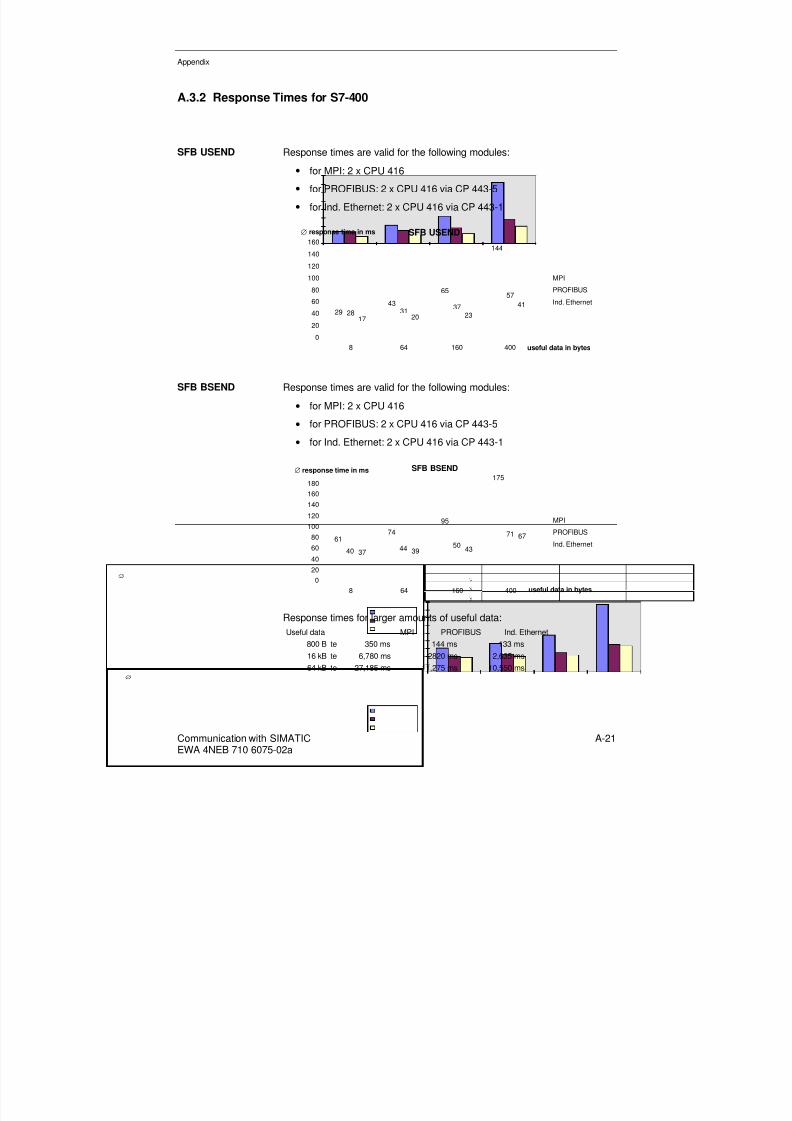
8/20/2019 Communication With Simatic Net
http://slidepdf.com/reader/full/communication-with-simatic-net 181/200
Appendix
Communication with SIMATICEWA 4NEB 710 6075-02a
A-21
A.3.2 Response Times for S7-400
SFB USEND Response times are valid for the following modules:• for MPI: 2 x CPU 416
• for PROFIBUS: 2 x CPU 416 via CP 443-5
• for Ind. Ethernet: 2 x CPU 416 via CP 443-1
SFB USEND
2943
65
144
28 31 37
57
17 20 2341
0
20
4060
80
100
120
140
160
8 64 160 400 useful data in bytes
∅ response time in ms
MPI
PROFIBUS
Ind. Ethernet
SFB BSEND Response times are valid for the following modules:
• for MPI: 2 x CPU 416
• for PROFIBUS: 2 x CPU 416 via CP 443-5
• for Ind. Ethernet: 2 x CPU 416 via CP 443-1
SFB BSEND
6174
95
175
40 44 50
71
37 39 43
67
0
20
40
60
80
100
120
140
160
180
8 64 160 400 useful data in bytes
∅ response time in ms
MPI
PROFIBUS
Ind. Ethernet
Response times for larger amounts of useful data:Useful data MPI PROFIBUS Ind. Ethernet
800 B te 350 ms 144 ms 133 ms
16 kB te 6,780 ms 2820 ms 2,635 ms
64 kB te 27,185 ms 11,275 ms 10,550 ms

8/20/2019 Communication With Simatic Net
http://slidepdf.com/reader/full/communication-with-simatic-net 182/200
Appendix
Communication with SIMATICEWA 4NEB 710 6075-02a
A-22
SFB PUT/GET Response times are valid for the following modules:
• for MPI: 2 x CPU 416
• for PROFIBUS: 2 x CPU 416 via CP 443-5
• for Ind. Ethernet: 2 x CPU 416 via CP 443-1
SFB PUT/GET
5670
89
167
39 42 49
72
35 37 42
67
020
40
60
80
100
120
140
160
180
8 64 160 400 useful data in bytes
∅ response time in ms
MPI
PROFIBUS
Ind. Ethernet
SFB PUT/GET zurS7-300
Response times are valid for the following modules:
• for MPI: CPU 416 and CPU 315
SFB PUT/GET
50
65
92
010
2030
4050
607080
90
100
8 64 160
useful data in bytes
∅ response time in ms
MPI

8/20/2019 Communication With Simatic Net
http://slidepdf.com/reader/full/communication-with-simatic-net 183/200
Appendix
Communication with SIMATICEWA 4NEB 710 6075-02a
A-23
Communicationwithin Subrack
Response times are valid for the following modules:
• 2 x CPU 416
Communication within Subrack
8 8 8
1315 16 16
23
15 15 16
26
0
5
10
15
20
25
30
8 64 160 400
useful data in bytes
∅ response time in ms
USEND
BSEND
PUT/GET
Response times for larger amounts of useful data:Useful data Res onse times
800 B te 49 ms
16 kB te 975 ms
64 kB te 3,900 ms
SFC X_SEND The following graph compares two different response times. With shortresponse times, the connections are maintained; with longer responsetimes, the connections are set up and cleared again for each data trans-mission.
Response times are valid for the following modules:
• for MPI: 2 x CPU 416
SFC X_SEND
61 66 74 77
182189 195 199
020
4060
80100
120140
160180
200
8 32 64 76 useful data in bytes
∅ response time in ms
Connections remain
C. are set up/cleared

8/20/2019 Communication With Simatic Net
http://slidepdf.com/reader/full/communication-with-simatic-net 184/200
Appendix
Communication with SIMATICEWA 4NEB 710 6075-02a
A-24
SFC X_PUT/X_GET The following graph compares two different response times. With shortresponse times, the connections are maintained; with longer responsetimes, the connections are set up and cleared again for each data trans-
mission.Response times are valid for the following modules:
• for MPI: 2 x CPU 416 and CPU 416 with CPU 215-2
SFC X_PUT/X_GET
56 62 66 73178 189
195 199200 200 200 200
600 600 600 600
0
100
200
300
400
500
600
8 32 64 76 useful data in bytes
∅ response time in ms
ConnectionsremainC. are set up/ clearedC. with 215-2remainC. with 215-2set up/cleared

8/20/2019 Communication With Simatic Net
http://slidepdf.com/reader/full/communication-with-simatic-net 185/200
Appendix
Communication with SIMATICEWA 4NEB 710 6075-02a
A-25
A.3.3 Response Times for S7-300
SFC X_SEND The following graph compares two different response times. With shortresponse times, the connections are maintained; with longer responsetimes, the connections are set up and cleared again for each data trans-mission.
Response times are valid for the following modules:
• for MPI: 2 x CPU 315
SFC X_SEND
48 48 53 60
202 206 213 216
0
50
100
150
200
250
8 32 64 76 useful data in bytes
∅ response time in ms
Connections remain
Conn. set up/cleared
SFC X_PUT/X_GET The following graph compares two different response times. With shortresponse times, the connections are maintained; with longer responsetimes, the connections are set up and cleared again for each data trans-
mission.Response times are valid for the following modules:
• for MPI: 2 x CPU 315 and CPU 315 with CPU 215-2
SFC X_PUT/X_GET
51 56 61 61
202 208 215 212200 200 200 200
600 600 600 600
0
100
200
300
400
500
600
8 32 64 76 useful data in bytes
∅ response time in ms
Connections remain
C. are set up/cleared
C. with 215-2 remain
C with 215-2 set up/cleared

8/20/2019 Communication With Simatic Net
http://slidepdf.com/reader/full/communication-with-simatic-net 186/200
Appendix
Communication with SIMATICEWA 4NEB 710 6075-02a
A-26
A.3.4 Response Times for M7-300/M7-400
SFB USEND Response times are valid for the following modules:• for MPI: 2 x CPU 388 and 2 x CPU 488
SFB USEND
2639
59
140
2842
58
143
0
20
40
60
80
100
120
140
160
8 64 160 400
useful data in bytes
∅ response time in ms
388
488
SFB BSEND Response times are valid for the following modules:
• for MPI: 2 x CPU 388 and 2 x CPU 488
SFB BSEND
4457
80
158
4759
83
161
0
20
40
60
80
100
120140
160
180
8 64 160 400
useful data in bytes
∅ response time in ms
388
488
Response times for larger amounts of useful data:Useful data CPU 388 CPU 488
800 B te 315 ms 316 ms16 kB te 6,085 ms 6,090 ms
64 kB te 23,015 ms 23,055 ms

8/20/2019 Communication With Simatic Net
http://slidepdf.com/reader/full/communication-with-simatic-net 187/200
Appendix
Communication with SIMATICEWA 4NEB 710 6075-02a
A-27
SFB PUT/GET Response times are valid for the following modules:
• for MPI: 2 x CPU 388 and 2 x CPU 488
SFB PUT/GET
3951
76
144
4254
79
147
0
20
40
60
80
100
120
140
160
8 64 160 400
useful data in bytes
∅ response time in ms
388
488
SFC X_SEND The following graph compares two different response times. With shortresponse times, the connections are maintained; with longer responsetimes, the connections are set up and cleared again for each data trans-mission.
Response times are valid for the following modules:
• für MPI: 2 x CPU 388 und 2 x CPU 488
SFC X_SEND
44 4957 59
143 149 157159
47 5159 62
145 150 157160
0
20
40
60
80
100
120
140
160
8 32 64 76 useful data in bytes
∅ response time in ms
Connections remain 388
C. are set up/cleared 388
Connections remain 488
C. are set up/cleared 488

8/20/2019 Communication With Simatic Net
http://slidepdf.com/reader/full/communication-with-simatic-net 188/200
Appendix
Communication with SIMATICEWA 4NEB 710 6075-02a
A-28
SFC X_PUT/X_GET The following graph compares two different response times. With shortresponse times, the connections are maintained; with longer responsetimes, the connections are set up and cleared again for each data trans-
mission.Response times are valid for the following modules:
• for MPI: 2 x CPU 388 and CPU 388 with CPU 215-2
SFC X_PUT/X_GET
38 45 52 54
140 145 152 155
100 100 100 100
300 300 300 300
0
50
100
150
200
250
300
8 32 64 76 useful data in bytes
∅ response time in ms
Connections remain
C. are set up/cleared
C. with 215 remain
C. with 215 set up/cleared
SFC X_PUT/X_GET The following graph compares two different response times. With shortresponse times, the connections are maintained; with longer responsetimes, the connections are set up and cleared again for each data trans-mission.
Response times are valid for the following modules:
• for MPI: 2 x CPU 488 and CPU 488 with CPU 215-2
SFC X_PUT/X_GET
45 48 54 57
145 150 157 160
100 100 100 100
400 400 400 400
0
50
100
150
200
250
300
350
400
8 32 64 76 useful data in bytes
∅ response time in ms
Connections remain
C. are set up/cleared
C. with 215 remain
C. with 215 set up/cleared

8/20/2019 Communication With Simatic Net
http://slidepdf.com/reader/full/communication-with-simatic-net 189/200
Appendix
Communication with SIMATICEWA 4NEB 710 6075-02a
A-29
Glossary
Address An address is the designation for a specific operand or operand area, e.g.
input I12.1; flag word FW25; data block DB3.
AddressAssignment
Assigning an address in the user program. Addresses can be assigned tospecific operands or operand areas (e.g. input I12.1; flag word FW25).
AT Advanced Technology. AT designates the PC standard of the second gen-eration, i.e. PCs with the ISA bus (16-bit data lines and 24-bit addresslines), Intel processors >= 80286, two interrupt controllers and hard disk.
BIOS Basic Input Output System - The term BIOS refers to the part of the soft-ware that establishes the link between the hardware and the operatingsystem drivers. The BIOS translates the hardware base into an abstract;the associated software is stored in an EPROM. The most important com-
ponents are, for example, the loader for the boot sector, the (hardware)SETUP for specifying the hardware configuration and for setting the timeof day.
Client/ServerPrinciple
When data is exchanged in accordance with the client/server principle, theclient always issues the communications tasks and the server executesthem.
COM Configuration Management - Configuration software for SIMATIC NETcommunication processors.
Complete Restart When a CPU starts up (following mode switching from STOP to RUN or byswitching ON at the main switch), and before cyclic program processing
starts (OB1), either the organization block OB101 (warm restart, only forS7-400) or the organization block OB 100 (complete restart) is first proc-essed. In the case of a complete restart, the process image of the inputs isread in and the STEP 7 user program is executed starting with the firstcommand in OB1.
Configuration This is the installation-specific combination of hardware and/or softwarecomponents.
Configuring This is the process of selecting and combining the separate components ofan automation system or installing the required software (e.g. operatingsystem on the M7 automation computer) and adapting it to the specificapplication (e.g. by parameterizing the modules).
Control CommandFREEZE
The DP master sends the control command FREEZE to a group of DPslaves and causes the DP slaves to freeze the status of their inputs at thecurrent value.

8/20/2019 Communication With Simatic Net
http://slidepdf.com/reader/full/communication-with-simatic-net 190/200
Appendix
Communication with SIMATICEWA 4NEB 710 6075-02a
A-30
Control CommandSYNC
The DP master sends the control command SYNC to a group of DP slavesand causes the DP slaves to synchronize the status of their outputs.
CP Communication Processor - Communication module for installing in acomputer or programmable controller.
CPU (CentralProcessing Unit)
The CPU is the central processing unit of the programmable controller orcomputer comprising control and computing mechanisms, memory, op-erating system and interfaces to signal modules and function modules.
Cycle Time The cycle time is the time that the CPU requires for processing the userprogram once.
Data Block (DB) In technical terms, a data block is a block of data whose operand is loadedinto the address register of the DB on opening. It provides memory spaceand data for all (global) code blocks (FC, FB or OB) that are to be exe-cuted. In contrast, the task of an instance data block is to act as specialmemory and data for the function block to which it has been assigned.
Data Consistency Data area that can be read or written by the operating system as a block inthe case of S7-300/400 CPUs (e.g. PUT/GET). This data area is inde-pendent of the size of useful data actually transferred by the communica-tions functions.
An array of the data types byte, word or double word can be transferredconsistent up to a maximum length that depends on the CPU used.
DB Data blocks are data areas in the user program that contain user data.There are global data blocks that can be accessed by all code blocks andinstance data blocks that are assigned to a specific FB call.
DDE Dynamic Data Exchange - This is a communications mechanism that al-lows Windows applications running in parallel to communicate with eachother. DDE makes a distinction between the server and the client. Theclient sends a task to the server via DDE which the server then executes.
DLL Dynamic Link Library - This is a collection of functions that are availableto several programs but which are only loaded into the memory once(Windows/Windows NT feature)
DP Distributed I/O comprises input and output modules that are implementeddecentralized with respect to the CPU (central processing unit of thecontroller). The SIMATIC system is linked to the distributed I/O via thePROFIBUS-DP bus system.
DP Protocol Protocol used to transfer data to distributed I/O via a DP network ->PROFIBUS-DP.

8/20/2019 Communication With Simatic Net
http://slidepdf.com/reader/full/communication-with-simatic-net 191/200
Appendix
Communication with SIMATICEWA 4NEB 710 6075-02a
A-31
DPRAM Dual Port Random Access Memory - This allows simultaneous accessfrom two computing components (CP and CPU) on one memory module(RAM).
ESD Guidelines Guidelines for the protection of Electrostatically Sensitive Devices.
FB Function Blocks, according to the IEC 1131-3 standard, are "code blockswith memory". A function block allows parameters to be transferred to theuser program. This means that FBs are especially suitable for program-ming frequently recurring complex functions such as closed-loop controland mode selection. Since an FB has a memory (instance data block) itsparameters (e.g. outputs) can be accessed at any time and at any point inthe user program.
FCs Function Calls are in accordance with the IEC 1131-3 standard "codeblocks without memory". A function call allows parameters to be trans-ferred to the user program. This means that function calls are especiallysuitable for programming frequently recurring complex functions such as
calculations. Important: Due to the lack of memory, the calculated valuesmust be processed immediately after the FC call.
FDL Fieldbus Data Link - Layer 2 of the ISO reference model in the case ofPROFIBUS; it comprises the sublayers "Fieldbus Link Control" (FCL) and"Medium Access Control" (MAC).
FM A Function Module (FM) is a module that relieves loading on the CPU inthe S7-300 and S7-400 programmable controllers caused by time-criticalor memory-intensive process signal processing tasks. FMs usually use theinternal communications bus for high-speed data exchange with the CPU.Examples of FM applications include counting, positioning and closed-loopcontrol.
FMS Fieldbus Message Specification - This constitutes the upper sublayer ofLayer 7 of the ISO reference model for PROFIBUS; it comprises the pro-tocol machine functions, generating the -> PDUs as well as encod-ing/decoding and interpretation of the protocol data unit.
FMS Protocol Protocol for data transfer via the PROFIBUS network in accordance withthe Fieldbus Message Specification.
HMI Human-machine interface: HMI systems can access the data areas of anS7 CPU or S7 objects of an M7. Process data can be visualized appropri-ately on HMI systems and operator control of installations is possible.
IM Interface Module (input/output module)
Industrial Ethernet Bus system for industrial use based on Ethernet (previously calledSINEC H1).

8/20/2019 Communication With Simatic Net
http://slidepdf.com/reader/full/communication-with-simatic-net 192/200
Appendix
Communication with SIMATICEWA 4NEB 710 6075-02a
A-32
Installation The installation is the sum total of all electrical equipment. An installationincludes programmable controllers, human-machine interfaces, bus sys-tems, field devices, drives, supply leads.
Instance This constitutes the call for a function block. Supposing a function block is
called five times in the STEP 7 user program, then five instances exist. Aninstance data block is assigned to each call.
Instance DataBlock (DB)
An instance data block stores the formal parameters and static local datafor function blocks. An instance data block can be assigned to an FB callor to a call hierarchy of function blocks.
IRQ Interrupt Request
ISA Industrial System Architecture - PC bus standard; ISA bus - Expansion busfor XT and AT computers (standardized 16-bit data and 24-bit addressbus).
ISO International Standard Organization - International organization based inGeneva which produces general standards, especially in the data trans-mission field.
Link Table Tables for defining the communication links between programmable mod-ules in a network.
Load into PLC Loadable objects (e.g. code blocks) are loaded from the programmingdevice into the load memory of a programmable module. This can takeplace via a programming device that is directly connected to the CPU or,for example, via PROFIBUS.
Load into
ProgrammingDevice
Loadable objects (e.g. code blocks) are loaded from the load memory of
the CPU into the programming device. This can take place via a pro-gramming device that is directly connected to the CPU or, for example,via PROFIBUS.
Logical Address This is the address under which a user program in the PLC can access anI/O signal.
Logical BaseAddress
Logical address of the first I/O signal of a module.
M7 RMOS32 M7 RMOS32 is the 32-bit real-time multi-tasking operating system for theM7 automation computer. M7 RMOS32 contains the M7 RMOS32 kerneland the M7 server as well as utility programs (RT, RFS, CLI, Debugger)
and libraries (C runtime library, DDE communication, RMOS-DOS/-Windows communication).

8/20/2019 Communication With Simatic Net
http://slidepdf.com/reader/full/communication-with-simatic-net 193/200
Appendix
Communication with SIMATICEWA 4NEB 710 6075-02a
A-33
M7–API M7–API (Application Programming Interface) is the call interface that isavailable to an M7 RMOS32 user program for the purpose of using theservices of the M7 server.
Memory Reset
(MRES)
The following memory areas of the CPU are reset on memory reset:
• User memory
• Read/write area of the load memory
• System memory with the exception of the MPI parameters and thediagnostics buffer.
MPI The Multi Point Interface is the programming device interface for SIMATICS7. It allows simultaneous use of several programming devices, textdisplays and operator panels on one or more CPUs. The stationsconnected to MPI are interconnected via a bus system.
MPI Address In an MPI network, a unique MPI address has to be assigned to eachprogrammable module.
MS-DOS Microsoft Disk Operating System is an operating system produced by theMicrosoft company. In the case of M7 RMOS32, the MS-DOS operatingsystem as well as an MS-DOS application can execute as an autonomous,low-priority M7 RMOS32 task.
Network A network comprises one or more coupled subnets with any number ofstations. Several networks can exist alongside each other. A commonnode table exists for each subnet.
Network Transition This is a connection point between subnets that belong to an overall net-work. This can also be a transition between subnets/networks that havedifferent characteristics (e.g. transition between PROFIBUS and IndustrialEthernet).
OCX OLE Custom Controls
OLE Object Linking and Embedding is the central architectural principle of theWindows versions Windows 95 and Windows NT 3.5 as well as formingthe basis of the Windows applications software under Windows for Work-groups 3.11.
OLM Optical Link Module

8/20/2019 Communication With Simatic Net
http://slidepdf.com/reader/full/communication-with-simatic-net 194/200
Appendix
Communication with SIMATICEWA 4NEB 710 6075-02a
A-34
Operating Mode The following operating modes can be set using the operating mode switchon the CPU :
• RUN with access to the STEP 7 user program, e.g. using the pro-gramming device (RUN-P)
• RUN with access protection (RUN)
• STOP and
• Memory reset (MRES).
Operating State The SIMATIC S7 system family features five different operating states:MEMORY RESET, STOP, START-UP, HALT and RUN. In the case of M7,the operating states are processed by the OMT server. The M7 RMOS32user program can only take into account the operating states of the M7when it is explicitly informed by the OMT server or FC server (only forSTART-UP and RUN).
Operating StateRUN In the RUN operating state, the user program is executed and the processimage is updated cyclically. All digital outputs are enabled.
Operating StateHALT
Changeover to the HALT operating state takes place from the RUN statein response to a request from the programming device. In this operatingstate, special test functions are possible.
Operating StateSTART-UP
The START-UP operating state is executed during transition from theSTOP operating state to the RUN operating state. It can be triggered bythe mode switch or following network ON or by entering commands at theprogramming device. In the case of the S7-300 a complete restart takesplace. In the case of the S7-400, either a complete restart or a warm re-start takes place depending on the position of the start-up mode switch.
Operating StateSTOP
Changeover to the STOP state takes place as a result of:
• Operating the operating mode switch
• An internal fault on the CPU
• A command entered at the programming device
In the "STOP" operating state, the user program does not execute. Allmodules are switched into a safe state. Certain programming functionsand operator control and visualization functions are possible.
Operating System This is an overall designation for all functions that control and monitor
execution of the user programs, distribution of resources among the sepa-rate user programs, and maintaining the operating mode in cooperationwith the hardware (e.g. MS-DOS).
Parameterization Parameterization is the process of setting the response for a module.

8/20/2019 Communication With Simatic Net
http://slidepdf.com/reader/full/communication-with-simatic-net 195/200
Appendix
Communication with SIMATICEWA 4NEB 710 6075-02a
A-35
PC Personal Computer
PCMCIA Personal Computer Memory Card International Association - Associationof about 450 member companies in the computer sector that aims tospecify worldwide standards for the miniaturization and flexible use of PCexpansion cards and to make this standard technology available on themarket. It cooperates with JEIDA (PC card standard for compact PC ex-pansion modules).
PDU Protocol Data Unit
PG Programming device for the SIMATIC product family of Siemens AG; usedfor programming, configuration, maintenance and for service.
PLC Programmable Logic Controller - PLCs are electronic controllers whosefunctions are stored in the controller in the form of a program. Theirhardware configuration and wiring is therefore independent of the functionof the controller.
The PLC has the structure of a computer; it comprises a CPU withmemory, input/output modules and an internal bus. The peripherals andthe programming language are optimized for the controller technology.
Procedure The sequence for data transfer in accordance with a specific technique inISO level 2 is also termed a procedure in the case of the point-to-pointlink.
Process Image The signal states for the digital input and output modules are stored in theCPU in a process image. A distinction is made between the process imagefor the inputs (PII) and the process image for the outputs (PIO).
Process Image for
the Inputs (PII)
The process image for the inputs is read from the input modules by the
operating system before the user program is executed.
Process Image forthe Outputs (PIO)
The process image for the outputs is transferred to the output modules atthe end of the user program by the operating system.
PROFIBUS Process Field Bus - A fieldbus to the EN 50170 standard Vol. 2PROFIBUS (DIN 19245; bus system for industrial use based onPROFIBUS; previously known as SINEC L2).
PROFIBUS-DP DP operating mode to DIN E 19245, Part 3; PROFIBUS-DP is a serial bus,specially developed by SIEMENS for the field level used to link to distant(distributed) I/O (previously know as L2/DP).
Project An S7 project encompasses all objects of an automation solution regard-less of the number of stations, modules and their networking.

8/20/2019 Communication With Simatic Net
http://slidepdf.com/reader/full/communication-with-simatic-net 196/200
Appendix
Communication with SIMATICEWA 4NEB 710 6075-02a
A-36
Protocol This is a procedural specification for the process of transferring data. Itdefines both the formats of the messages and the data flow during trans-fer.
Rack A rack is a module rack comprising slots in which modules are inserted.
S7 Manager STEP 7 tool. All configuration and parameterization required for aSIMATIC S7 system can be performed under the user interface of the S7Manager.
S7 Object S7 objects on an M7 represent the operand area of an S7 CPU. Via S7objects, an M7 can communicate with other SIMATIC components (e.g.HMI systems, programming devices, S7 CPUs). S7 objects are createdand managed by the "Object server". S7 objects of an M7 comprise, forexample, all process data, data blocks or bit memory areas.
S7 PLC This is an abbreviation for a programmable logic controller of theSIMATIC S7 product family of Siemens AG.
S7 Program The S7 program encompasses blocks, source code and schedules forprogrammable S7 modules.
S7 Protocol The S7 protocol (also known as "S7 communication" or "S7 functions")forms a simple and efficient interface between SIMATIC S7 stations and tothe programming device or PC.
SCSI Small Computer System Interface - Interface for connecting SCSI devices(e.g. hard disk drives, CD-ROM drives).
Services These are the services offered by a communication protocol.
SIMATIC Manager Graphical user-interface for SIMATIC users under Windows 95.
SIMATIC NET Siemens product name for networks and network components (previouslySINEC).
SINEC Siemens Network and Communication -> SIMATIC NET.
SINEC H1 -> Industrial Ethernet
SINEC L2 -> PROFIBUS
Standard FunctionBlock
Standard function blocks are function blocks which can be purchased fromSiemens. They form, for example, the interface between the user program
and complex I/O modules or between the user program and the communi-cations processor. Standard function blocks are also available for closed-loop control, alarm functions, operator control and process visualization,arithmetic, Graph 5 and complex mathematical functions.

8/20/2019 Communication With Simatic Net
http://slidepdf.com/reader/full/communication-with-simatic-net 197/200
Appendix
Communication with SIMATICEWA 4NEB 710 6075-02a
A-37
START-UP The START-UP operating state is the transition from the STOP operatingstate to the RUN operating state. In the START-UP state, some pro-gramming may be required specifically for preparing for process control inthe RUN state.
Station This is a complete unit that can be connected to one or more subnets, e.g.programmable controller, programming device, operator station.
Station Address A unit (e.g. programming device) or a programmable module (e.g. CPU)can be accessed in a subnet (e.g. MPI, PROFIBUS) via the station ad-dress.
Subnet This is the sum total of all physical components that are required to estab-lish a data transmission path, as well as the common procedure requiredto transfer data.
The stations on a subnet are interconnected without the need for networktransitions. The physical entirety of a subnet (MPI, PROFIBUS, Industrial
Ethernet) is also known as the transfer medium.System Data Block(SDB)
System data blocks are data blocks in the CPU which contain system set-tings and module parameters. The system data blocks are generated andmodified on configuration.
System Function(SFC)
A system function (SFC) is a function that is integrated into the operatingsystem of the CPU and that can be called up in the STEP 7 user programif necessary.
System FunctionBlock (SFB)
A system function block (SFB) is a function block that is integrated into theoperating system of the CPU and that can be called up in the STEP 7 userprogram if necessary.
User Program The user program contains all instructions and declarations as well as datafor the signal processing that is used to control an installation or a process.It is associated with a programmable module (e.g. CPU, FM) and can bestructured into smaller units (blocks).
Variable A variable is a data item with a variable content that can be used in theSTEP 7 user program. A variable comprises an operand (e.g. M 3.1) and adata type (e.g. Bool) and can be identified by a symbol (e.g. BAND_EIN).
VBA Visual Basic for Applications
VBX Visual Basic Extension - Extension of Visual Basic for developing user-specific operator control elements.
VMD Virtual Manufacturing Device - This is the abstraction of a device whosecharacteristics are represented by a section of the application.

8/20/2019 Communication With Simatic Net
http://slidepdf.com/reader/full/communication-with-simatic-net 198/200
Appendix
Communication with SIMATICEWA 4NEB 710 6075-02a
A-38
Warm Restart When a CPU starts up (e.g. following changeover of the mode switch fromSTOP to RUN or by switching ON at the main switch) either the organiza-tion block OB 100 (complete restart) or the organization block OB 101(warm restart, only for S7-400) is processed before cyclic program proc-essing starts (OB 1). In the case of a warm restart, the process image of
the inputs is read in and execution of the STEP 7 user program is contin-ued, starting from the point at which is was previously interrupted (viaSTOP or POWER OFF).
Warm Start A warm start is a restart that takes place after a program has aborted. Theoperating system is reloaded and restarted. A warm start can be activatedusing the key combination CTRL + ALT + DEL.

8/20/2019 Communication With Simatic Net
http://slidepdf.com/reader/full/communication-with-simatic-net 199/200
Appendix

8/20/2019 Communication With Simatic Net
http://slidepdf.com/reader/full/communication-with-simatic-net 200/200
Appendix