Embed Size (px)
Citation preview
Preface, Contents
Introduction 1
Functionality 2
Commissioning 3
MP270 Operation 4
Operating Screens and Screen Objects 5
Recipes 6
Archives 7
System Settings 8
Installation 9
Unit Description 10
Options 11
Maintenance/Upkeep 12
Operating System Update 13
Appendices
A
EGlossary, Index
Release 03/01
6AV6591–1DB01–2AB0
Multi PanelMP270
Equipment Manual
SIMATIC HMI

!Dangerindicates an imminently hazardous situation which, if not avoided, will result in death or serious injury.
!Warningindicates a potentially hazardous situation which, if not avoided, could result in death or serious injury.
!Cautionused with the safety alert symbol indicates a potentially hazardous situation which, if not avoided, may result inminor or moderate injury.
Cautionused without safety alert symbol indicates a potentially hazardous situation which, if not avoided, may result inproperty damage.
Attentionindicates that unwanted events or unwanted status can occur if the relevant information is not observed.
Qualified PersonnelEquipment may be commissioned and operated only by qualified personnel. Qualified personnel within themeaning of the safety notices in this manual are persons who are authorized to commission, ground and iden-tify equipment, systems and circuits in accordance with safety engineering standards.
Correct UsageNote the following:
!WarningThe equipment may be used only for the applications stipulated in the catalog and in the technical descriptionand only in conjunction wit other equipment and components recommended or approved by Siemens.
Startup must not take place until it is established that the machine, which is to accommodate this component,is in conformity with the guideline 89/392/ECC.
Faultless and safe operation of the product presupposes proper transportation, proper storage, erection andinstallation as well as careful operation and maintenance.
ApprovalsThe approvals that apply to the device are detailed in Appendix A.
TrademarksThe registered trademarks of the Siemens AG can be found in the preface. The remaining trademarks in thispublication may be trademarks, whose use by third parties for their own purposes could violate the rights of theowner.
ImpressumEditor and Publisher: A&D PT1.
Safety GuidelinesThis manual contains notices which you should observe to ensure your own personal safety, as well as toprotect the product and connected equipment. These notices are marked as follows according to the levelof danger:
We have checked the contents of this manual for agreement with the hard-ware and software described. Since deviations cannot be precluded entirely,we cannot guarantee full agreement. However, the data in this manual arereviewed regularly and any necessary corrections included in subsequenteditions. Suggestions for improvement are welcomed.
Disclaim of LiabilityCopyright Siemens AG 2001 All rights reserved
The reproduction, transmission or use of this document or its contents is notpermitted without express written authority. Offenders will be liable fordamages. All rights, including rights created by patent grant or registration ofan utility model or design, are reserved.
Siemens AGAutomation & DrivesSIMATIC Human Machine InterfacePostfach 4848, D-90327 Nuernberg
� Siemens AG 2001Technical data subject to change.
Siemens Aktiengesellschaft Order no: 6AV6591–1DB01–2AB0

iMP270 Equipment ManualRelease 03/01
Preface
This manual
The MP270 equipment manual is part of the SIMATIC HMI documentation. Itprovides operation, installation, configuration and system personnel withinformation concerning installation, functionality, operation and technical design ofthe MP270.
An overview of the entire SIMATIC HMI documentation is provided in Appendix E.
Organization of the manual
The MP270 equipment manual is organized into the following chapters:
Chapter Contents
1 - 2 Overview of features and functional scope of the MP270
3 - 5 Commissioning and operation
6 - 7 Recipes and archives
8 System settings
9 - 12 Mechanical and electrical installation, unit description, retrofitting ofoptions as well as maintenance and upkeep of the MP270
13 Information on updating the operating system.
Appendix � Technical Data
� Interface Assignments
� System Messages
� ESD Guidelines
� SIMATIC HMI Documentation

Preface
iiMP270 Equipment Manual
Release 03/01
Conventions
The following conventions are used throughout this manual:
Motor off Text in the operating unit display is presented in thistypewriter font.
Tag Symbolic names representing tag values on the screen arepresented in this italic typewriter font.
Screens Functions available for selection are presented in this italicfont.
ESC The names of keys and buttons are displayed in a differentfont.
History
The various editions of this manual relate to the following modifications to thedevice:
Edition Comment
01/99 First release of the MP270 equipment manual.
12/99 Recipes, archives, new screen objects, MPI transfer, networkoperation, Alarm_S
03/01 New key combinations, communication options, functions for datarecords, system messages

Preface
iiiMP270 Equipment ManualRelease 03/01
Trademarks
The following names are registered trademarks of the Siemens AG:
� HMI�
� IndustrialX�
� MP270�
� MP370�
� ProAgent�
� ProTool�
� ProTool/Lite�
� ProTool/Pro�
� SIMATIC�
� SIMATIC HMI�
� SIMATIC Multi Panel�
� SIMATIC Multifunctional Platform�
� WinCC�
� WinCC Add-on�

Preface
ivMP270 Equipment Manual
Release 03/01
Other support
In the case of technical queries, please contact the Siemens representatives in thesubsidiaries and branches responsible for your area.
Customer Support, Technical Support
Available worldwide, at all times:
Johnson City
Nuernberg
Singapur
SIMATIC Hotline
Worldwide (Nuernberg)
Technical Support
(FreeContact)
Local time Mo. - Fr. 7:00 to 17:00
Telephone: +49 (180) 5050-222
Fax: +49 (180) 5050-223
E-Mail: [email protected]
GMT: +1:00
Worldwide (Nuernberg)
Technical Support
(charged, only with SIMATIC Card)Local time Mo. - Fr. 0:00 to 24:00
Telephone: +49 (911) 895-7777
Fax: +49 (911) 895-7001
GMT: +01:00
Europe / Africa (Nuernberg)
Authorization
Local time Mo. - Fr. 7:00 to 17:00
Telephone: +49 (911) 895-7200
Fax: +49 (911) 895-7201
E-Mail: [email protected]
GMT: +1:00
America (Johnson City)
Technical Support andAuthorizationLocal time Mo. - Fr. 8:00 to 19:00
Telephone: +1 423 461-2522
Fax: +1 423 461-2289
E-Mail: [email protected]
GMT: -5:00
Asia / Australia (Singapur)
Technical Support andAuthorizationLocal time Mo. - Fr. 8:30 to 17:30
Telephone: +65 740-7000
Fax: +65 740-7001
E-Mail: [email protected]
GMT: +8:00
The languages provided on the SIMATIC Hotlines are generally English and German, the Authorization Hotline is alsoprovided in French, Italian and Spanish.

Preface
vMP270 Equipment ManualRelease 03/01
SIMATIC Customer Support Online Services
SIMATIC Customer Support offers comprehensive additional informationconcerning SIMATIC products through its Online services as follows:
� Up-to-date general information is provided
– in Internet under http://www.ad.siemens.de/simatic
� Up-to-date product information and downloads for practical use can be found:
– in Internet under http://www.ad.siemens.de/simatic-cs
– via the Bulletin Board System (BBS) in Nürnberg (SIMATIC CustomerSupport Mailbox) under the number +49 (911) 895-7100.
To dial the mailbox use a modem with up to V.34 (28.8 kbaud) with theparameters set as follows: 8, N, 1, ANSI, or dial via ISDN (x.75, 64 kbit).
� Your local contact partner for Automation & Drives can be found in the contactpartner database.
– in Internet underhttp://www3.ad.siemens.de/partner/search.asp
Abbreviations
The abbreviations used in this equipment manual have the following meaning:
AG (PLC) Programmable Logic Controller
ANSI American National Standards Institute
AS 511 Protocol of the PU interface to SIMATIC S5
ASCII American Standard Code for Information Interchange
CCFL Cold Cathode Fluorescence Lamp
CF Compact Flash
CPU Central Processing Unit
CSV Comma Separated Values
DC Direct Current
DHCP Dynamic Host Configuration Protocol
DNS Domain Name Service
DP Decentralized Periphery
DSN Data Source Name
EMC Electromagnetic compatibility
ESD Electrostatically Sensitive Device
HMI Human Machine Interface
IF Interface
LCD Liquid Crystal Display
LED Light Emitting Diode

Preface
viMP270 Equipment Manual
Release 03/01
MP Multi Panel
MPI Multipoint Interface (SIMATIC S7)
OP Operator Panel
PC Personal Computer
PCL Printer Control Language
PLC Programmable Logic Controller
PPI Point to Point Interface (SIMATIC S7)
PU Programming Unit
STN Super Twisted Nematic
TCP/IP Transmission Control Protocol/Internet Protocol
TFT Thin Film Transistor
TTL Transistor-Transistor Logic
UNC Universal Naming Convention
WINS Windows Internet Name Service
A list of all the specialist terms together with their explanations is provided in theGlossary at the end of this manual.

viiMP270 Equipment ManualRelease 03/01
Contents
1 Introduction 1-1. . . . . . . . . . . . . . . . . . . . . . . . . . . . . . . . . . . . . . . . . . . . . . . . . . . . . . . . . . . .
2 Functionality 2-1. . . . . . . . . . . . . . . . . . . . . . . . . . . . . . . . . . . . . . . . . . . . . . . . . . . . . . . . . . .
3 Commissioning 3-1. . . . . . . . . . . . . . . . . . . . . . . . . . . . . . . . . . . . . . . . . . . . . . . . . . . . . . . .
3.1 Initial Startup 3-3. . . . . . . . . . . . . . . . . . . . . . . . . . . . . . . . . . . . . . . . . . . . . . . . . . .
3.2 Recommissioning 3-4. . . . . . . . . . . . . . . . . . . . . . . . . . . . . . . . . . . . . . . . . . . . . . . 3.2.1 Start downloading manually 3-4. . . . . . . . . . . . . . . . . . . . . . . . . . . . . . . . . . . . . . 3.2.2 Start downloading automatically 3-5. . . . . . . . . . . . . . . . . . . . . . . . . . . . . . . . . . 3.2.3 Minimizing downloading times 3-6. . . . . . . . . . . . . . . . . . . . . . . . . . . . . . . . . . . . .
3.3 Options for Download Mode 3-7. . . . . . . . . . . . . . . . . . . . . . . . . . . . . . . . . . . . . .
3.4 Test the Configuration on the MP270 3-11. . . . . . . . . . . . . . . . . . . . . . . . . . . . . . .
3.5 Download Back 3-13. . . . . . . . . . . . . . . . . . . . . . . . . . . . . . . . . . . . . . . . . . . . . . . . .
3.6 Backup/Restore the Internal Flash Memory 3-15. . . . . . . . . . . . . . . . . . . . . . . . .
4 MP270 Operation 4-1. . . . . . . . . . . . . . . . . . . . . . . . . . . . . . . . . . . . . . . . . . . . . . . . . . . . . . .
4.1 Integrated Keyboard 4-1. . . . . . . . . . . . . . . . . . . . . . . . . . . . . . . . . . . . . . . . . . . . . 4.1.1 Function keys/Softkeys 4-2. . . . . . . . . . . . . . . . . . . . . . . . . . . . . . . . . . . . . . . . . . 4.1.2 System keys 4-3. . . . . . . . . . . . . . . . . . . . . . . . . . . . . . . . . . . . . . . . . . . . . . . . . . . .
4.2 Key Combinations 4-5. . . . . . . . . . . . . . . . . . . . . . . . . . . . . . . . . . . . . . . . . . . . . . .
4.3 Entering Values 4-9. . . . . . . . . . . . . . . . . . . . . . . . . . . . . . . . . . . . . . . . . . . . . . . . . 4.3.1 Enter numeric values 4-10. . . . . . . . . . . . . . . . . . . . . . . . . . . . . . . . . . . . . . . . . . . . 4.3.2 Enter alphanumeric values 4-11. . . . . . . . . . . . . . . . . . . . . . . . . . . . . . . . . . . . . . .
4.4 Call Help Text 4-12. . . . . . . . . . . . . . . . . . . . . . . . . . . . . . . . . . . . . . . . . . . . . . . . . . .
5 Operating Screens and Screen Objects 5-1. . . . . . . . . . . . . . . . . . . . . . . . . . . . . . . . . .
5.1 Operating Screens 5-2. . . . . . . . . . . . . . . . . . . . . . . . . . . . . . . . . . . . . . . . . . . . . .
5.2 Logging On and Off from the MP270 5-5. . . . . . . . . . . . . . . . . . . . . . . . . . . . . . .
5.3 Overview of Screen Objects 5-6. . . . . . . . . . . . . . . . . . . . . . . . . . . . . . . . . . . . . .
5.4 Input Field 5-9. . . . . . . . . . . . . . . . . . . . . . . . . . . . . . . . . . . . . . . . . . . . . . . . . . . . . .
5.5 Selection Field 5-11. . . . . . . . . . . . . . . . . . . . . . . . . . . . . . . . . . . . . . . . . . . . . . . . .
5.6 Buttons 5-12. . . . . . . . . . . . . . . . . . . . . . . . . . . . . . . . . . . . . . . . . . . . . . . . . . . . . . . .
5.7 Status Button 5-13. . . . . . . . . . . . . . . . . . . . . . . . . . . . . . . . . . . . . . . . . . . . . . . . . . .
5.8 Switch 5-15. . . . . . . . . . . . . . . . . . . . . . . . . . . . . . . . . . . . . . . . . . . . . . . . . . . . . . . . .
5.9 Messages 5-16. . . . . . . . . . . . . . . . . . . . . . . . . . . . . . . . . . . . . . . . . . . . . . . . . . . . . .

Contents
viiiMP270 Equipment Manual
Release 03/01
5.9.1 ALARM_S 5-18. . . . . . . . . . . . . . . . . . . . . . . . . . . . . . . . . . . . . . . . . . . . . . . . . . . . . . 5.9.2 Message line 5-19. . . . . . . . . . . . . . . . . . . . . . . . . . . . . . . . . . . . . . . . . . . . . . . . . . . 5.9.3 Message window 5-19. . . . . . . . . . . . . . . . . . . . . . . . . . . . . . . . . . . . . . . . . . . . . . . . 5.9.4 Message page 5-21. . . . . . . . . . . . . . . . . . . . . . . . . . . . . . . . . . . . . . . . . . . . . . . . . . 5.9.5 Message buffer 5-22. . . . . . . . . . . . . . . . . . . . . . . . . . . . . . . . . . . . . . . . . . . . . . . . . 5.9.6 Message view 5-23. . . . . . . . . . . . . . . . . . . . . . . . . . . . . . . . . . . . . . . . . . . . . . . . . . 5.9.7 Simple message view 5-24. . . . . . . . . . . . . . . . . . . . . . . . . . . . . . . . . . . . . . . . . . . .
5.10 Bar Graphs 5-25. . . . . . . . . . . . . . . . . . . . . . . . . . . . . . . . . . . . . . . . . . . . . . . . . . . . .
5.11 Trend View 5-26. . . . . . . . . . . . . . . . . . . . . . . . . . . . . . . . . . . . . . . . . . . . . . . . . . . . .
5.12 Slider Control 5-28. . . . . . . . . . . . . . . . . . . . . . . . . . . . . . . . . . . . . . . . . . . . . . . . . . .
5.13 Analog Display 5-29. . . . . . . . . . . . . . . . . . . . . . . . . . . . . . . . . . . . . . . . . . . . . . . . . .
5.14 Date/Time 5-30. . . . . . . . . . . . . . . . . . . . . . . . . . . . . . . . . . . . . . . . . . . . . . . . . . . . . .
5.15 Digital/Analog Clock 5-32. . . . . . . . . . . . . . . . . . . . . . . . . . . . . . . . . . . . . . . . . . . . .
5.16 Password List 5-33. . . . . . . . . . . . . . . . . . . . . . . . . . . . . . . . . . . . . . . . . . . . . . . . . . 5.16.1 Password management 5-34. . . . . . . . . . . . . . . . . . . . . . . . . . . . . . . . . . . . . . . . . . 5.16.2 Export/Import password list 5-35. . . . . . . . . . . . . . . . . . . . . . . . . . . . . . . . . . . . . . .
5.17 Status/Force 5-36. . . . . . . . . . . . . . . . . . . . . . . . . . . . . . . . . . . . . . . . . . . . . . . . . . . .
6 Recipes 6-1. . . . . . . . . . . . . . . . . . . . . . . . . . . . . . . . . . . . . . . . . . . . . . . . . . . . . . . . . . . . . . . .
6.1 Overview 6-1. . . . . . . . . . . . . . . . . . . . . . . . . . . . . . . . . . . . . . . . . . . . . . . . . . . . . . .
6.2 Recipe Configuration 6-3. . . . . . . . . . . . . . . . . . . . . . . . . . . . . . . . . . . . . . . . . . . .
6.3 Editing Data Records 6-6. . . . . . . . . . . . . . . . . . . . . . . . . . . . . . . . . . . . . . . . . . . . 6.3.1 Recipe view 6-7. . . . . . . . . . . . . . . . . . . . . . . . . . . . . . . . . . . . . . . . . . . . . . . . . . . . 6.3.2 Recipe screens 6-15. . . . . . . . . . . . . . . . . . . . . . . . . . . . . . . . . . . . . . . . . . . . . . . . . 6.3.3 Functions and PLC jobs 6-17. . . . . . . . . . . . . . . . . . . . . . . . . . . . . . . . . . . . . . . . . . 6.3.4 Import/Export data records 6-18. . . . . . . . . . . . . . . . . . . . . . . . . . . . . . . . . . . . . . . 6.3.5 Reaction on changing the recipe structure 6-21. . . . . . . . . . . . . . . . . . . . . . . . . .
7 Archives 7-1. . . . . . . . . . . . . . . . . . . . . . . . . . . . . . . . . . . . . . . . . . . . . . . . . . . . . . . . . . . . . . .
8 System Settings 8-1. . . . . . . . . . . . . . . . . . . . . . . . . . . . . . . . . . . . . . . . . . . . . . . . . . . . . . . .
8.1 Set Language 8-2. . . . . . . . . . . . . . . . . . . . . . . . . . . . . . . . . . . . . . . . . . . . . . . . . . .
8.2 Setting an Operating Mode 8-3. . . . . . . . . . . . . . . . . . . . . . . . . . . . . . . . . . . . . . .
8.3 Screen Settings 8-4. . . . . . . . . . . . . . . . . . . . . . . . . . . . . . . . . . . . . . . . . . . . . . . . .
8.4 Control Panel Settings 8-5. . . . . . . . . . . . . . . . . . . . . . . . . . . . . . . . . . . . . . . . . . . 8.4.1 Communication 8-6. . . . . . . . . . . . . . . . . . . . . . . . . . . . . . . . . . . . . . . . . . . . . . . . . 8.4.2 Set date/time 8-6. . . . . . . . . . . . . . . . . . . . . . . . . . . . . . . . . . . . . . . . . . . . . . . . . . . 8.4.3 Network 8-7. . . . . . . . . . . . . . . . . . . . . . . . . . . . . . . . . . . . . . . . . . . . . . . . . . . . . . . . 8.4.4 OP properties 8-7. . . . . . . . . . . . . . . . . . . . . . . . . . . . . . . . . . . . . . . . . . . . . . . . . . . 8.4.5 Language setting 8-7. . . . . . . . . . . . . . . . . . . . . . . . . . . . . . . . . . . . . . . . . . . . . . . . 8.4.6 Set printer 8-8. . . . . . . . . . . . . . . . . . . . . . . . . . . . . . . . . . . . . . . . . . . . . . . . . . . . . .
8.5 Network Operation 8-9. . . . . . . . . . . . . . . . . . . . . . . . . . . . . . . . . . . . . . . . . . . . . . 8.5.1 Conditions for network operation 8-9. . . . . . . . . . . . . . . . . . . . . . . . . . . . . . . . . . 8.5.2 Configure MP270 8-10. . . . . . . . . . . . . . . . . . . . . . . . . . . . . . . . . . . . . . . . . . . . . . . . 8.5.3 Test network 8-12. . . . . . . . . . . . . . . . . . . . . . . . . . . . . . . . . . . . . . . . . . . . . . . . . . . . 8.5.4 Configure network functions 8-12. . . . . . . . . . . . . . . . . . . . . . . . . . . . . . . . . . . . . .

Contents
ixMP270 Equipment ManualRelease 03/01
9 Installation 9-1. . . . . . . . . . . . . . . . . . . . . . . . . . . . . . . . . . . . . . . . . . . . . . . . . . . . . . . . . . . . .
9.1 Mechanical Installation 9-2. . . . . . . . . . . . . . . . . . . . . . . . . . . . . . . . . . . . . . . . . . .
9.2 Electrical Installation 9-4. . . . . . . . . . . . . . . . . . . . . . . . . . . . . . . . . . . . . . . . . . . . . 9.2.1 Connect configuration computer 9-8. . . . . . . . . . . . . . . . . . . . . . . . . . . . . . . . . . . 9.2.2 Connect PLC 9-9. . . . . . . . . . . . . . . . . . . . . . . . . . . . . . . . . . . . . . . . . . . . . . . . . . . 9.2.3 Connect printer 9-11. . . . . . . . . . . . . . . . . . . . . . . . . . . . . . . . . . . . . . . . . . . . . . . . .
10 Unit Description 10-1. . . . . . . . . . . . . . . . . . . . . . . . . . . . . . . . . . . . . . . . . . . . . . . . . . . . . . . .
10.1 Dimensions 10-2. . . . . . . . . . . . . . . . . . . . . . . . . . . . . . . . . . . . . . . . . . . . . . . . . . . . .
10.2 Labeling Function Keys 10-3. . . . . . . . . . . . . . . . . . . . . . . . . . . . . . . . . . . . . . . . . .
11 Options 11-1. . . . . . . . . . . . . . . . . . . . . . . . . . . . . . . . . . . . . . . . . . . . . . . . . . . . . . . . . . . . . . . .
11.1 Backup Battery 11-2. . . . . . . . . . . . . . . . . . . . . . . . . . . . . . . . . . . . . . . . . . . . . . . . .
11.2 Memory Card/Network Card 11-3. . . . . . . . . . . . . . . . . . . . . . . . . . . . . . . . . . . . . .
12 Maintenance/Upkeep 12-1. . . . . . . . . . . . . . . . . . . . . . . . . . . . . . . . . . . . . . . . . . . . . . . . . . . .
12.1 Clean Screen and Keyboard Foil 12-1. . . . . . . . . . . . . . . . . . . . . . . . . . . . . . . . . .
12.2 Replacing the Optional Backup Battery 12-2. . . . . . . . . . . . . . . . . . . . . . . . . . . . .
13 Operating System Update 13-1. . . . . . . . . . . . . . . . . . . . . . . . . . . . . . . . . . . . . . . . . . . . . . .
Appendices
A Technical Data A-1. . . . . . . . . . . . . . . . . . . . . . . . . . . . . . . . . . . . . . . . . . . . . . . . . . . . . . . . .
B Interface Assignment B-1. . . . . . . . . . . . . . . . . . . . . . . . . . . . . . . . . . . . . . . . . . . . . . . . . . .
C System Messages C-1. . . . . . . . . . . . . . . . . . . . . . . . . . . . . . . . . . . . . . . . . . . . . . . . . . . . . .
D ESD Guidelines D-1. . . . . . . . . . . . . . . . . . . . . . . . . . . . . . . . . . . . . . . . . . . . . . . . . . . . . . . .
E SIMATIC HMI Documentation E-1. . . . . . . . . . . . . . . . . . . . . . . . . . . . . . . . . . . . . . . . . . . .

Contents
xMP270 Equipment Manual
Release 03/01
1-1MP270 Equipment ManualRelease 03/01
Introduction
Multifunctional platform
The SIMATIC Multi Panels are included in the new product category“Multifunctional Platform”. This product category is positioned in the producthierarchy between the optimized process and application components, such asoperator panels and PLCs on the one hand, and industrial PCs on the other.
The multifunctional platform is based on the innovative standard operating systemMicrosoft Windows CE. It combines the robustness of the dedicated hardwaresolutions with the flexibility of the PC world.
Multi Panels include the following features:
� Clear display and easy operation of the process by means of a Windows-baseduser interface
� Large selection of predefined screen objects during configuration
� Uncomplicated and quick handling of recipes and data records in recipescreens and recipe views
� the archiving of messages and process values
� Dynamic use of screen objects (e.g. moving objects)
� Simulation of the configuration on a configuration computer
� Creation of vector graphics using the SIMATIC ProTool CS configurationsoftware without an external graphics editor
� Visual Basic Script for the realization of customized functions
� Alarm_S message procedure in connection with the SIMATIC S7
� Downloading:
– Automatic switchover to Download mode
– Downloading via MPI and PROFIBUS/DP
– Serial downloading
– Downloading via TeleService
� Standard connections to SIMATIC S5, SIMATIC S7 and SIMATIC 505 as wellas to PLCs from other manufacturers
A complete overview of the functional range of the MP270 is provided in Chapter 2.
1

Introduction
1-2MP270 Equipment Manual
Release 03/01
Area of use of the MP270
The MP270 has been conceived for easy machine operation and monitoring. Itprovides a realistic graphical representation of the machine or system to bemonitored. Their area of use include implementation in machine and apparatusconstruction as well as in the packing and electronics industry.
The high degree of protection (IP65 on the front side) and non-implementation ofmoving storage media, such as hard disks and floppy disks, ensure the MP270 isalso suitable for use in rough industrial environments and directly on site on therespective machine.
Installation locations for the MP270:
� Panels/Consoles
� 19’’ cabinets/racks
Due to the fact that the MP270 is equipped with high performance basic hardwareand has a minimum installation depth means that it fulfills all the requirements foroperation in the vicinity of the machine.
Easy to operate and observe
The MP270 enables operating statuses, current process values and errorsconcerning a connected PLC to be graphically displayed and the relevant machineor system to be easily monitored and operated. Display and operation of theMP270 can be adapted optimally for the respective process requirements by usingthe ProTool CS configuration software and, for example, extended by user-definedfunctions with the user’s own scripts.
The MP270 can be used to:
� control and monitor the process by means of the menu system. Setpoint valuesor control element settings, for instance, can be modified by entering values oractivating configured function keys;
� display processes, machines and systems on full-graphic, dynamic screens;
� display and edit messages and process tags e.g. in output fields, bar graphs,trend views or status views;
� intervene directly in the running process by using the integrated keyboard.

Introduction
1-3MP270 Equipment ManualRelease 03/01
Configuration using ProTool CS
Graphics, texts, customized functions and operating and display elements whichneed to be represented on the MP270 must first be created on a configurationcomputer (PC or PU) using the configuration software.
In order to download the configuration to the MP270, the configuration computermust be connected to the MP270 (refer to “Configuration phase” in Figure 1-1).The connection can be either direct or established via an MPI/PROFIBUS-DPnetwork, for example.
Once the configuration has been successfully downloaded, connect the MP270 tothe PLC. Communication is then possible between the MP270 and PLC and theMP270 can subsequently respond to the program process in the PLC according tothe configured instructions (refer to “Process running phase” in Fig. 1-1).
Create project dataSave project dataTest the configurationSimulate configuration
Download project data
Connected to PLC
Configuration phase
������������� ���
PC/PU
PLC
MP270
Figure 1-1 Configuration and process running phase

Introduction
1-4MP270 Equipment Manual
Release 03/01
General overview of the MP270
Overview: MP270 version
Processor Type 32 bit CPU
Configurationmemory
Capacity To 4 Mbyte
Software Operating system Microsoft Windows CE
Interfaces Serial interface for connection toPLC, PC/PU, printer
1 × RS232/TTY (active/passive)
1 × RS232 (9-pin)
1 × RS422/RS485
Display Type TFT LCD STN LCD
Active screen area (W × H) inmm
211 × 158 (10.4 ’’)
Resolution (pixels) 640 × 480
Colors 256
Back-lighting CCFL tube
Service life, approx. (h) 40,000 50,000
Membrane keyboard System keys with dedicatedfunctions
33 (3 with LEDs)
Function keys with configurablefunctions
36 (28 with LEDs)
Those usable as softkeys 20
Labeling the function keys System-specific with labelling strips
Special features � External memory extension:
– Slot for PC card
– Slot for CF card
� Optional network card

Introduction
1-5MP270 Equipment ManualRelease 03/01
Further information
Detailed information on the technical data of the MP270 is provided in Appendix Aof this manual.
Detailed descriptions of the creation of projects for the MP270 and configurationsoftware functions are provided in the ProTool Configuring Windows-basedSystems user’s guide and in the online help for ProTool CS.
Connection of the MP270 to the PLC is described in the Communication forWindows-based Systems user’s guide.
Any new information which could not be taken into account for printing in theguides is provided in the Readme.wri file on the ProTool CD.

Introduction
1-6MP270 Equipment Manual
Release 03/01

2-1MP270 Equipment ManualRelease 03/01
Functionality
The following table summarizes the range of functions provided by the MP270. The valuesspecified are the maximum values which can be managed by the MP270. These values are notaccumulative, i.e. 4000 messages can be configured if no further objects are used. However, itis not possible to define 4000 messages and 200 pictures each with 200 tags simultaneously.The defined values are limited by the size of the configuration memory.
Function Comment
Messages Number 4,000
Display In message line/messagewindow/message view
View all pending messages Message page/Message view
Message length 70 characters
Process values in message text 8
Color-coding of differentmessage states
Event messages
Alarm messages
� Type of display first/last, selectable� Acknowledge individual
messages� Acknowledge several alarm
messages simultaneously(group acknowledgement)
16 acknowledgment groups
ALARM_S Display S7 messages
Message logging Output to printer
Volatile message buffer Capacity 1,024 message events
View messages
Delete
Message events queuedsimultaneously (max.)� Event messages
or
500
� Alarm messages/ALARM_S 250
Message buffer archive Memory location CSV file
Capacity Limited by storage medium (PC card, CF card, network drive)
2

Functionality
2-2MP270 Equipment Manual
Release 03/01
CommentFunction
Message acquisition Time of occurrence Date and time
Message events Arrived, departed, acknowledged
Screens Number 200
Fields per screen 200
Tags per screen 200
Complex elements per screen(trends, bar graphs, etc.)
10
View
Print (hardcopy)
Screen objects � Text
� Graphics
� Output field
� Input field
� Symbolic output field
� Selection field
� Date and time
� Graphics list
� Vector graphic
� Button
� Status button
� Switches
� Hidden button
� Trend view
� Bar
� Message view
� Simple message view
� Status/Force
� Password list
� Recipe display
� Slider controls
� Analog display
� Digital/Analog clock
Operator prompting
� Help text
� Dynamic attributes
� Call/Hide objects
� Icons for softkeys
� TAB sequence
� LEDs in function keys
Fixed window
Tags Number 2,048
Limit value monitoring Inputs/outputs
Functionality
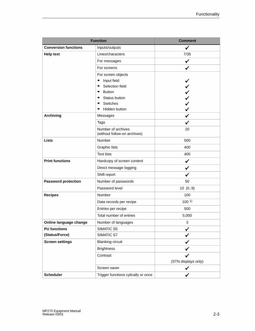
2-3MP270 Equipment ManualRelease 03/01
CommentFunction
Conversion functions Inputs/outputs
Help text Lines/characters 7/35
For messages
For screens
For screen objects
� Input field
� Selection field
� Button
� Status button
� Switches
� Hidden button
Archiving Messages
Tags
Number of archives (without follow-on archives)
20
Lists Number 500
Graphic lists 400
Text lists 400
Print functions Hardcopy of screen content
Direct message logging
Shift report
Password protection Number of passwords 50
Password level 10 (0..9)
Recipes Number 100
Data records per recipe 100 1)
Entries per recipe 500
Total number of entries 5,000
Online language change Number of languages 3
PU functions SIMATIC S5
(Status/Force) SIMATIC S7
Screen settings Blanking circuit
Brightness
Contrast
(STN displays only)
Screen saver
Scheduler Trigger functions cylically or once

Functionality
2-4MP270 Equipment Manual
Release 03/01
CommentFunction
VB Script User-specific expansions offunctionality
Number of scripts 50
Number of lines per script 20
Connections 2) Number 6
Communication SIMATIC S5
� AS511
� PROFIBUS-DP
SIMATIC S7
� MPI
� PROFIBUS-DP
SIMATIC 505
� NITP
� PROFIBUS-DP
SIMOTION
Connection to PLCs from other manufacturers
Allen Bradley (PLC-5, SLC 500)
� DF1
� DH+ 3)
� DH485 3)
LG (Lucky Goldstar)
� GLOFA GM
Modicon
� Modbus
Mitsubishi FX
Telemecanique TSX
� Adjust
� Uni-Telway
1) The internal Flash memory has a maximum storage capacity of 64 kByte2) With SIMATIC S73) Via external module

3-1MP270 Equipment ManualRelease 03/01
Commissioning
In this chapter
This chapter provides information on:
� Initial start-up of the MP270 (Page 3-3)
� Recommissioning the MP270 (Page 3-4)
� Options for download mode (Page 3-7)
� Testing the configuration on the MP270 (Page 3-11)
� Downloading the configuration back 3-13)
� Backup/Restore the internal Flash memory (Page 3-15)
Notice
In the case of the Initial start-up, please observe the safety notes concerningreverse poling protection on Page 9-6.
3

Commissioning
3-2MP270 Equipment Manual
Release 03/01
Switch off voltage supply
Caution
Always terminate the runtime software before switching off the voltage supply inorder to prevent loss of data.
To terminate the runtime software, press the operating element assigned theExit_runtime function in the configuration. Wait until the MP270 start menu(Figure 3-1, Page 3-7) appears and then switch off the power supply.
Operating the MP270 in the start-up phase
During the MP270 start-up phase it is possible to set the options for Downloadmode and to modify various system settings.
Step Action
1 Select the object to be operated (button, check box or input field) usingthe Tabulator key.
The object currently selected is marked by a border or a different color.
2 � Buttons/Check boxes:Press the Enter key in order to trigger the marked button oractivate/deactivate the marked check box.
� Input fields:Complete the modification/input and confirm the entry by pressingthe Enter key.
Further information on operating the MP270 is provided in the following chapters:
� General Operation: Chapter 4
� Operating Special Screen Objects: Chapter 5

Commissioning
3-3MP270 Equipment ManualRelease 03/01
3.1 Initial Startup
Action
When the operating unit is started up for the first time, no configuration has beenloaded on it. In order to download the necessary project data and the runtimesoftware from the configuration computer to the MP270, proceed as follows,observing the sequence:
Step Action
1 Switch on the MP270’s power supply.Please observe the safety notes concerning reverse poling protection onPage 9-6.
2 Connect the MP270 to the configuration computer according to the settings inthe Config Settings menu (Figure 3-2, Page 3-8) via the IF2 (serial) or IF1B(MPI/PROFIBUS-DP) interface using a standard cable.
3 If necessary, check the interface settings in the Config Settings menu (Figure 3-2, Page 3-8) and adapt them as required.
4 If data should be downloaded via an MPI connection, set the followingparameters on the configuration computer:
� OP address: 1
� Transmission rate: 187.5 kBaud
5 Start downloading the configuration on the configuration computer. Furthersettings necessary on the configuration computer for the download operation areprovided in the ProTool Configuring Windows-based Systems user’s guide.
The configuration computer checks the connection to the MP270. If theconnection is not available or defective, the corresponding error messageappears.
If downloading from the configuration computer is terminated as a result of acompatibility conflict, please continue as described in Chapter 13.
If the connection is correct, the project data is downloaded to the MP270. Whendownloading has been completed successfully, the MP270 starts the newconfiguration.
Set date/time
When the MP270 is disconnected from the power supply for a longer periodwithout the backup battery being used, the date and time must be updated.Information on this is available on Page 5-30.

Commissioning
3-4MP270 Equipment Manual
Release 03/01
3.2 Recommissioning
PurposeDuring recommissioning, a configuration already loaded on the MP270 is replacedby another. In this case, the project data is downloaded from the configurationcomputer to the MP270.
The following options are available to switch the MP270 to Download mode:
� Start downloading during the start-up phase of the MP270 manually(Page 3-4)
� Start downloading during normal operation of the MP270 automatically(Page 3-5)
� Start downloading via a correspondingly configured operating element while theMP270 is in operation (Page 8-3)
3.2.1 Start downloading manually
Start downloading during the start-up phase of the MP270 manually:
Step Action
1 Switch on the MP270’s power supply.Please observe the safety notes concerning reverse poling protection onPage 9-6.
2 Connect interface IF2 (serial) or IF1B (MPI/PROFIBUS-DP) of the MP270 usingan appropriate standard cable.
3 If necessary, check the interface settings in the Configuration menu (Figure 3-2,Page 3-8) and adapt them as required.
4 During the start-up phase of the MP270, the menu depicted in Figure 3-1(Page 3-7) appears briefly. Press the Download button to set the operating unitto Download mode before the start-up routine is completed.The operating unit continues to display the message Connecting to hostuntil it receives data from the configuration computer or the Cancel button ispressed.If the message Connecting to host does not appear, it is probable that theoptions for download mode have been incorrectly set (refer to Page 3-8).
5 If downloading is to be performed via an MPI connection, set the OP addressand transmission rate currently valid for the MP270 on the configurationcomputer (refer to Step 4 on Page 3-3).
6 Start downloading the configuration on the configuration computer.
The configuration computer checks the connection to the MP270. If theconnection is not available or defective, the configuration computer issues thecorresponding error message.
If downloading from the configuration computer is terminated as a result of acompatibility conflict, please continue as described in Chapter 13.
If the connection is correct, the new configuration is downloaded to the MP270.When downloading has been completed successfully, the MP270 starts the newconfiguration.

Commissioning
3-5MP270 Equipment ManualRelease 03/01
3.2.2 Start downloading automatically
Configuration menu settings
The MP270 can be switched to download mode automatically when in normaloperation as soon as downloading is started on the connected configurationcomputer. This option is particularly recommended for the test phase involving anew configuration project because the data is transferred without having tointervene on the MP270. A condition for this is that the following settings havebeen defined in the Config Settings menu (Figure 3-2, Page 3-8):
Connection via MPI/PROFIBUS-DP:� Option MPI/DP Transfer Enable is activated� Option MPI/DP Transfer Remote Control is activated
Serial connection:� Option Serial Transfer Enable is activated� Option Serial Transfer Remote Control is activated
A detailed description of the settings possible in the Config Settings menu is
provided on Page 3-8.
!Warning
Following the start-up phase, switch the automatic download option off to preventinadvertently switching the MP270 to Download mode in a system which isrunning. Deactivate the options MPI/DP Transfer Remote Control and SerialTransfer Remote Control in the MP270 Configuration (Figure 3-2, Page 3-8).
Notice
The bus parameters (e.g. MPI address, baud rate etc.) currently loaded on theMP270 are read out of the configuration.
Only use these parameters when downloading a new configuration via MPI, evenif different parameters are configured for the new configuration, because the newparameters only take effect after downloading has been completed successfully.
Notice
If the MP270 should switch to Download mode automatically via the configurationcomputer connected, no “modal dialogs” may be active on the MP270 at thatmoment. Modal dialogs e.g. Login Dialog) are dialogs which must be closed beforeother dialogs can be operated.
In such cases, close the dialog or interrupt downloading on the configurationcomputer.

Commissioning
3-6MP270 Equipment Manual
Release 03/01
3.2.3 Minimizing downloading times
Load configuration from external memory card
Downloading configurations on the MP270 can take quite a long time, particularlyin the case of large configurations. The downloading times can be minimized,e.g. for commissioning, by loading modified configurations onto the MP270 from anexternal memory card (PC or CF card).
Condition
The following conditions must be fulfilled in order to download a configuration froman external memory card to the MP270:
� The memory card is defined in the Config Settings menu (Fig. 3-2, Page 3-8)under the item Projectfile path.
� The configuration has already been downloaded once to the MP270 via MPI/DPor serial transfer.
� The modifications, in relation to the version already downloaded, do not containany new object types, PLCs or languages.
Action
Proceed as follows to download a configuration to the MP270 from an externalmemory card:
Step Action
1 Copy the project file (*.fwd) generated to the configuration computer inpdata.fwd.
2 Switch off the voltage supply for the MP270.
3 Remove the memory card from the MP270 and insert it in the configurationcomputer.
4 Overwrite the pdata.fwd file on the memory card with the new project file.
5 Insert the memory card back in the MP270.
6 Switch on the voltage supply for the MP270.
Notice
In the case of comprehensive modifications, always download the configurationusing the configuration software ProTool because this is the only method by whichthe functionality of the new objects can be guaranteed.

Commissioning
3-7MP270 Equipment ManualRelease 03/01
3.3 Options for Download Mode
Overview
The following options can be set for download mode:
� Automatic switching to download mode from normal operation when datatransfer is initiated from the connected configuration computer
� Download mode can be restricted to a specific connection type so thatdownloading can only occur either via a serial connection or anMPI/PROFIBUS-DP connection.
Call in Configuration menu
The options for download mode can only be set during the MP270 start-up phase.During the start-up phase the Start menu depicted in Figure 3-1 appears. Pressthe Config button to call in the Config Settings menu depicted in Figure 3-2.
Figure 3-1 MP270 Start menu
The configuration can be started manually by pressing the Start button. Otherwise,the MP270 starts the configuration automatically approx. 10 seconds afterswitching it on.
Use the Control button to open the Windows CE Control Panel in which to modifysystem settings. Information on this is provided on Page 8-5.
Information concerning the two buttons Backup and Restore is provided onPage 3-15.
Commissioning
3-8MP270 Equipment Manual
Release 03/01
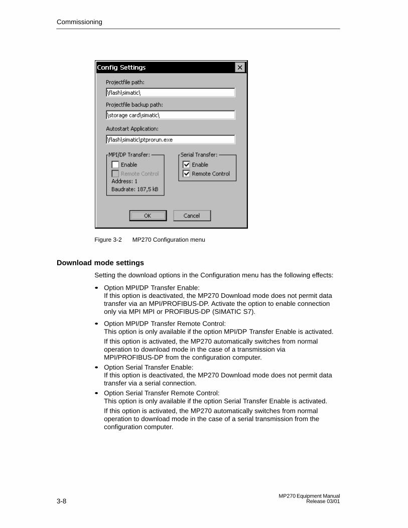
Figure 3-2 MP270 Configuration menu
Download mode settings
Setting the download options in the Configuration menu has the following effects:
� Option MPI/DP Transfer Enable:If this option is deactivated, the MP270 Download mode does not permit datatransfer via an MPI/PROFIBUS-DP. Activate the option to enable connectiononly via MPI MPI or PROFIBUS-DP (SIMATIC S7).
� Option MPI/DP Transfer Remote Control:This option is only available if the option MPI/DP Transfer Enable is activated.
If this option is activated, the MP270 automatically switches from normaloperation to download mode in the case of a transmission viaMPI/PROFIBUS-DP from the configuration computer.
� Option Serial Transfer Enable:If this option is deactivated, the MP270 Download mode does not permit datatransfer via a serial connection.
� Option Serial Transfer Remote Control:This option is only available if the option Serial Transfer Enable is activated.
If this option is activated, the MP270 automatically switches from normaloperation to download mode in the case of a serial transmission from theconfiguration computer.

Commissioning
3-9MP270 Equipment ManualRelease 03/01
Press the OK button to confirm the settings currently defined for the downloadoptions. The Configuration menu is closed and the Start menu depicted inFigure 3-1 appears.
Press the Cancel button to close the Configuration menu and access the Startmenu depicted in Figure 3-1. Any modifications made to the settings are rejected.
The group MPI/DP Transfer displays both bus parameters, Address and BaudRate. This parameters are valid for the configuration currently loaded on theMP270.
!Warning
When the option Remote Control is active, ensure that the MP270 is notinadvertently switched to download mode from the configuration computer when innormal operation.
Notice� If the two options MPI/DP Transfer Enable and Serial Transfer Enable are
deactivated, it is not possible to download a configuration from theconfiguration computer to the MP270.
� Deactivate the Serial Transfer Remote Control option if a serial printer isconnected to the MP270.
Further settings in the Configuration menu
In addition to the setting options for download mode, the MP270 Configurationmenu also contains input fields for the following paths:
� Projectfile path:The predefined storage location for your project file can be changed here.The internal Flash memory, PC card and CF card can be defined. During thenext downloading operation, the configuration is stored in the specified storagelocation.
� Projectfile backup path:The predefined storage location for a backup of the source file of yourconfiguration can be changed here. This file can be used for restoring(downloading back ) the configuration (*.pdb). The internal Flash memory, PCcard and CF card can be defined.
Information on downloading back is provided on Page 3-13.
� Autostart application:This defines the storage location for the ProTool runtime software. This is theapplication with which the configuration runs under Windows CE on the MP270.

Commissioning
3-10MP270 Equipment Manual
Release 03/01
Notice
Do not change the setting in this field when working with ProTool. Otherwise,the MP270 can no longer start your configuration.
Exit Start menu
If the MP270 still has no configuration, it automatically switches to Download modeapprox. 10 seconds after switching it on. The MP270 can be switched to Downloadmode manually by pressing the Download button.
If the MP270 already contains a configuration it is started automatically approx.10 seconds after switching it on. The configuration can be started immediately bypressing the Start button.

Commissioning
3-11MP270 Equipment ManualRelease 03/01
3.4 Test the Configuration on the MP270
Conditions
In order to switch the operating unit between the operating modes OFFLINE andONLINE, the function Change_mode must be linked to an operating element in theconfiguration.
TipDuring the test phase, it is recommended to enable switching to download modefrom normal operation. Further information on this is provided on Page 3-5.
!Warning
After the test phase, do not forget to deactivate the Remote Control option toprevent inadvertently switching to Download mode from the configurationcomputer when in normal operation.
Testing on the configuration computer
The material supplied with ProTool contains a simulation program which can beused to test the configuration on the configuration computer without the necessityof connecting a PLC or operating unit. Detailed information on this is provided inthe ProTool Configuring Windows-based Systems and in the online help to ProToolCS.
Testing without a PLC connected (OFFLINE mode)
After setting the MP270 to operating mode OFFLINE, the individual projectfunctions can be tested without them being affected by the PLC. PLC tags are notupdated in OFFLINE mode.
Step Action
1 Switch the MP270 to operating mode OFFLINE (refer to Page 8-3).
2 Check all the configured screens in respect of correct representation.
3 Check the screen hierarchy.
4 Check the input fields.
5 Test the function keys.

Commissioning
3-12MP270 Equipment Manual
Release 03/01
Testing with a PLC connected (ONLINE mode)
When a PLC is connected, it is possible to test the communication between theMP270 and PLC in ONLINE mode. This includes checking that the correct dataareas have been configured.
Step Action
1 Connect the MP270 to the PLC.
2 Test all the items in the configuration for which communication with the PLC isnecessary e.g.:
� messages,
� print functions,
� automatic message logging,
� selecting screens etc.

Commissioning
3-13MP270 Equipment ManualRelease 03/01
3.5 Download Back
Purpose
During downloading, generally only the run-capable configuration (*.fwd) which hasbeen generated is downloaded on the MP270. If the original project file is to beused for further development of the configuration or for fault analysis, it mustremain on the configuration computer.
Not only the generated configuration can be stored on the MP270, but also thesource file (*.pdb) of the configuration, so that it can be retrieved (downloadedback) from the MP270 later, if necessary.
Advantage
After downloading a configuration back, it can be analyzed and modified even if theoriginal configuration computer cannot be accessed or the source file (*.pdb) on itfor the configuration is no longer available.
Conditions
The following conditions must be fulfilled in order to retrieve the source file from therun-capable project file:
� Sufficient memory space must be available on the MP270 for the additionalsource file.
� The storage location of the source file must be defined on the MP270 (refer toPage 3-9 under “Projectfile backup path”)
� Downloading of the current project file from the configuration computer to theMP270 must be performed using the option Download Back Enabled.
Proceed as follows:
1. Select the menu option File → Download
2. in the ProTool configuration software
3. Define the download mode
4. Activate the checkbox Download Back Enabled in the Download Selection
5. dialog.
What happens during download/download back?
In the case of downloading including transfer of the source file, the configuration iscompressed from the source format (*.pdb) and downloaded to the MP270 as a*.pdz file. After downloading back, the file is decompressed in the ProTool CSconfiguration software.
Give the configuration a new name on the configuration computer (refer toinstructions on Page 3-14).

Commissioning
3-14MP270 Equipment Manual
Release 03/01
Notice� The downloaded back, decompressed file can only be opened with a
ProTool CS whose version number is greater or equal to that of theconfiguration software with which the project was created.
� ProTool CS cannot check whether the source file on the MP270 matches theconfiguration actually run on it. If downloading is performed at any time withoutthe option Download Back being activated, it is possible that old project data ison the MP270 which no longer matches the current project.
InstructionsDownloading a configuration back from the MP270:
Step Action
1 Select the menu option File Download Back in ProTool CS on the configurationcomputer.
2 Select one of the two following connection types between the MP270 andconfiguration computer in the Download Back Settings dialog:� Serial� MPI/PROFIBUS-DP (via network connection)
3 Click on Edit and set the connection parameters:� for serial: connection and baud rate� for MPI/PROFIBUS-DP: OP address of the MP270
The settings are saved and correspondingly reapplied when downloading backis triggered at a later date.
4 Switch the MP270 to download mode manually or using Remote Controlaccording to the setting in the Configuration menu.
5 Start downloading back with OK.
Download back automatically switches the MP270 to download mode.Condition: The download type used is set on the MP270 (refer to Page 3-8).Following successful downloading back, the Save as dialog opens.
6 Enter a new name or select an existing configuration to be overwritten and clickSave.
The configuration retrieved is saved and automatically opened in ProTool CS.
Alternative for large project files
Download the project file as a compressed *.arj file, on a CF card, for example. Todo this, use the backup function of the ProTool configuration software.
Switch ProTool to Stand-alone mode prior to doing this if you are working inSTEP 7 which has been integrated. To do this, press the Switch ProTool Integrationin STEP 7 button in the ProTool Setup.

Commissioning
3-15MP270 Equipment ManualRelease 03/01
3.6 Backup/Restore the Internal Flash Memory
Purpose
The functions Backup and Restore provide the following options:
� creating a copy of the entire configuration on a memory card
� restoring a stored configuration in the case of a fault
� updating a configuration regardless of where the MP270 is in use, without aconfiguration computer
Conditions
The two functions Backup and Restore are only available in the Start menu(Figure 3-1, Page 3-7) during the start-up phase of the MP270. In order to accessthe Start menu, either the Exit_runtime function must be called in or the unitrestarted.
Insert the memory card in the relevant expansion slot before starting theBackup/Restore process:
� PC card: Slot A
� CF card: Slot B
Notice� Before inserting the memory card, please observe the safety notes concerning
reverse poling protection on Page 9-6.
� The MP270 uses a plug-in memory card for Backup/Restore. If both slots areoccupied when Backup/Restore is initiated, the PC card (Slot A) is used first.
In case of doubt, remove the memory card not to be used from the MP270.
Information on the memory cards which can be used is provided in Chapter 11.2.

Commissioning
3-16MP270 Equipment Manual
Release 03/01
Backup
During a backup process, the operating system, application and data are copiedfrom the internal Flash memory to an external storage medium.
Proceed as follows to create a backup copy of the internal Flash memory:
Step Action
1 Deactivate the write protection on the memory card, if set.
2 Insert the memory card in one of the two slots, A or B, according to the targetmedium (refer to Figure 9-1, Page 9-5).
3 Call in the MP270 Start menu (Figure 3-1, Page 3-7).
4 Start the Backup process by using the Backup button.
5 Confirm the deletion of any existing backup files beforehand.
6 When the data has been completely downloaded, the MP270 issues a message.
7 Remove the memory card from the MP270.
8 Activate the write protection on the memory card, if available.
9 Label the memory card e.g. with the date and version of the configuration savedand keep it in a safe place.
Restore
In the case of a restore process, the content of a Flash memory stored on anexternal storage medium is reloaded into the internal Flash memory. Both systemdata and configuration data are copied. Prior to this, the MP270 Flash memory iscompletely cleared following confirmation.
Proceed as follows to restore the content of the internal Flash memory:
Step Action
1 Activate the write protection on the memory card, if available.
2 Insert the memory card in one of the two slots, A or B, according to the targetmedium (refer to Figure 9-1, Page 9-5).
3 Call in the MP270 Start menu (Figure 3-1, Page 3-7).
4 Start the restore process by clicking on the Restore button.
5 Before starting the Restore process, the MP270 checks the compatibility with thedata to be restored. In the case of incompatibility, the MP270 terminates theprocess and issues the relevant message.
6 Confirm that the internal Flash memory.
7 When the data has been completely downloaded, the MP270 issues a message.
8 Remove the memory card from the MP270.
9 Switch on the voltage supply for the MP270.

4-1MP270 Equipment ManualRelease 03/01
MP270 Operation
Operating concept
The operating status of the machine or system to be monitored can be observedon the MP270 screen and the running process directly influenced by using thekeyboard.
This chapter provides information on the general operating procedures for theMP270. Information regarding operation of screens and screen objects is providedin Chapter 5.
4.1 Integrated Keyboard
KeypadsThe MP270 consists of two functional blocks (Figure 4-1):
� Function keys/Softkeys (Keys K1 to K16 and F1 to F20)
� System keys
Function keys/Softkeys System keys
Figure 4-1 Assignment of the keypads
4

MP270 Operation
4-2MP270 Equipment Manual
Release 03/01
4.1.1 Function keys/Softkeys
!Caution
Do not press more than one function key/softkey at a time. Doing somay inadvertently trigger certain functions in some circumstances.
Function keys for global function assignment
A function key for global function assignment always triggers the same action onthe MP270 or in the PLC regardless of the screen currently open (globalsignificance on the MP270). These actions could include:
� Open screen
� Display current alarm messages
� Print screen (hardcopy)
The following function keys can be assigned during configuration:
...
...
Function keys for local function assignment (softkeys)
A function key for local function assignment (softkey) can trigger different actionson the MP270 or in the PLC according to the screen currently open (localsignificance of current screen). If configured, the function of a softkey is indicatedby an icon located at the edge of the current screen (refer to Page 5-2).
All the function keys located directly at the edge of the screen can be assignedglobally or locally significant functions during configuration. This concerns thefollowing keys in the case of the MP270:
...
!Caution
If a function key is pressed directly following changing screens, the correspondingfunction associated with the new screen is triggered before the screen isgenerated.
MP270 Operation
4-3MP270 Equipment ManualRelease 03/01
LED assignment
The Light Emitting Diodes (LEDs) in the function keys can be controlled from thePLC. A luminous or flashing LED can indicate to the operator which key to pressaccording to specific situations, for example.
In order to trigger LEDs, the corresponding data areas – so called mappers – mustbe set up in the PLC and specified as area pointers in the configuration. Theassignment of the individual LEDs to the bits in the database must be defined bythe project engineer when configuring the function keys. In this case, the bitnumber within the mapping area is specified for each LED.
Detailed information on LED control is provided in the Communication forWindows-based Systems user’s guide.
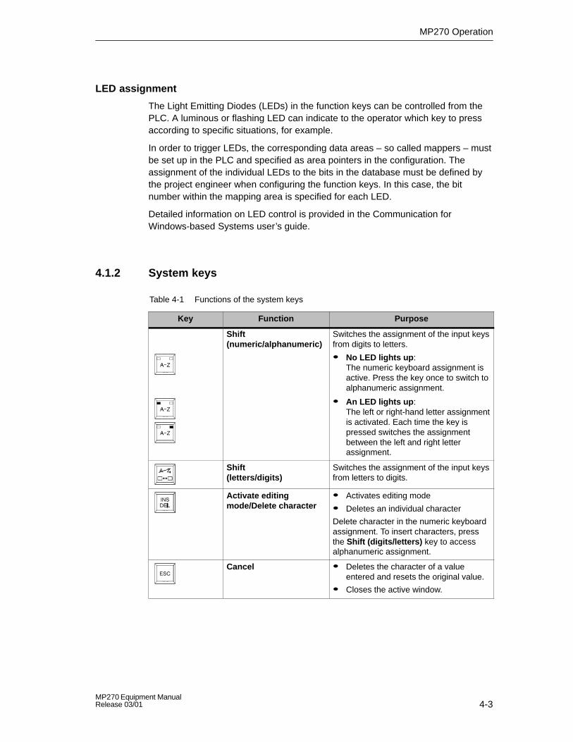
4.1.2 System keys
Table 4-1 Functions of the system keys
Key Function Purpose
Shift(numeric/alphanumeric)
Switches the assignment of the input keysfrom digits to letters.
� No LED lights up:The numeric keyboard assignment isactive. Press the key once to switch toalphanumeric assignment.
� An LED lights up:The left or right-hand letter assignmentis activated. Each time the key ispressed switches the assignmentbetween the left and right letterassignment.
Shift(letters/digits)
Switches the assignment of the input keysfrom letters to digits.
Activate editingmode/Delete character
� Activates editing mode
� Deletes an individual character
Delete character in the numeric keyboardassignment. To insert characters, pressthe Shift (digits/letters) key to accessalphanumeric assignment.
Cancel � Deletes the character of a valueentered and resets the original value.
� Closes the active window.

MP270 Operation
4-4MP270 Equipment Manual
Release 03/01
Table 4-1 Functions of the system keys, continued
PurposeFunctionKey
Acknowledge Acknowledges the currently displayedalarm message or all messages in anacknowledgment group (groupacknowledgement).
The LED lights up as long asunacknowledged alarm messages arequeued.
Display help text Opens a window with help text in respectof the selected object (message, inputfield). The LED indicates if help text existsfor the selected object.
Acknowledge � Accepts and ends the input
� Opens a selection field for symbolicinput
� Triggers the function on the selectedbutton
Tabulator Moves to the next screen object availablefor selection in the configured tabulationsequence.
Delete character Deletes the character to the left of thecursor.
Move cursor � Move to the next screen objectavailable for selection to the right, left,above or below the current screenobject.
� Navigation in the screen object.
Shift(upper/lower case)
Use in combination with other keys, e.g.Shift, switch to capital letters.
General control function Use in combination with other keys, e.g.navigation in trend view
General control function Use in combination with other keys, e.g.Status/Force

MP270 Operation
4-5MP270 Equipment ManualRelease 03/01
4.2 Key Combinations
Special characters
Use the following key combinations with the SHIFT key pressed to enter additionalcharacters on the MP270. Press the Shift (letters/digits) key beforehand toswitch to the digit assignment.
Key combination Character Unicode
} 125
! 033
“ 034
| 124
~ 126
% 037
& 038
{ 123
[ 091
] 093
# 035
> 062
< 060
? 063
_ 095

MP270 Operation
4-6MP270 Equipment Manual
Release 03/01
General operation
Key combination Function
Navigation
Moves to the previous screen object available for selection in theconfigured tabulation sequence.
Positions the cursor within a screen object, e.g. in an input field.
Opens a selection field.
Screen settings
Increases the screen contrast (for STN displays only).
Reduces the screen contrast (for STN displays only).
Increases the screen brightness.
Reduces the screen brightness.
During the start-up phase
Switches the MP270 to download mode.
As long as no data transfer is taking place, it is possible to exitfrom download mode.
Other functions
Accepts the selected value in the selection field without closing it.
� Changes the active window.
� Switches between basic area and window.
Mark all
Display the properties of the marked element.

MP270 Operation
4-7MP270 Equipment ManualRelease 03/01
Navigation in the operating system
Key combination Function
Opens the operating system Start menu.
Open the Task Manager.
Explorer:
Switch to superordinate level.
Switches the display area.
Activates the menu bar.
Dialogs:
Move to next field.
Move to previous field.
Opens the next tab control. 1)
Opens the previous tab control. 1)
Close the dialog without saving.
1) When the name of the tab control has the focus.
Cursor control compatibility
The type of cursor control, e.g. within tabular structured screen objects (messageview, recipe view and status/force), can be configured. Two variants can beconfigured in ProTool CS:
� Cursor control as with V 5.10
� New cursor control
All the examples in this manual relate to the new cursor control. The new cursorcontrol enables navigation within tables and selection fields simply by using thecursor keys without having to simultaneously implement the SHIFT key.

MP270 Operation
4-8MP270 Equipment Manual
Release 03/01
Navigation using function keys
If the following functions are linked to function keys or softkeys in the configuration,it is also possible to navigate through the MP270 using the function keys:
� Page_Up Simulates the function assigned to the Page Up key.
� Page_Down Simulates the function assigned to the Page Down key.
� Go_to_Home Simulates the function assigned to the Home key.
� Go_to_End Simulates the function assigned to the END key.
These functions are complied in ProTool CS within the Keyboard group.
Operating screen objects using function keys
Screen objects assigned to buttons, e.g. message view, trend view, recipe view orstatus/force, can also operated by means of function keys or softkeys. A conditionfor this is that each relevant function has been linked to a function key or softkey inthe configuration.
These functions are complied in ProTool CS within the Keyboard action for screenobjects.

MP270 Operation
4-9MP270 Equipment ManualRelease 03/01
4.3 Entering Values
Marking
On selecting an input field, the entire field content is marked by changing color.After pressing a key (except a cursor key), the field content is deleted and the newinput displayed.
After selecting a field, press the SHIFT key and a cursor key simultaneously toclear the marking on the field contents and enable the cursor to be moved freelywithin the field.
Operation
Proceed as follows to enter values in an input field:
Step Action
1 Use the cursor keys to position the cursor on the desired input field.
2 Enter the value in the following form, according to the configuration:
� Numeric (Page 4-10)
� Alphanumeric (Page 4-11)
� Symbolic (Page 5-11)
3 Confirm the entry.

MP270 Operation
4-10MP270 Equipment Manual
Release 03/01
4.3.1 Enter numeric values
Action
Numeric values are entered character by character using the input keys on thekeyboard. If a value already exists in the field, this is deleted on entering the firstcharacter. After beginning entering a value, it is impossible to exit from the fieldwithout either confirming the entry or canceling it.
Possible values
The following values are possible in numeric input fields:
Values Keys Description
Decimal...
The input keys are numerically assigned....
,
Hexadecimal...
...
To enter the characters A...F switch the inputkeys to alphanumeric assignment.
Digits,
The input keys are numerically assigned.
Limit value check
Limit values can be configured for numeric input fields. In this case, valuesentered are only accepted when they lie within the limits configured. If an attemptis made to enter a value which is outside the configured limits, it is rejected and theoriginal value automatically reinserted. In this case, the MP270 issues a systemmessage.

MP270 Operation
4-11MP270 Equipment ManualRelease 03/01
4.3.2 Enter alphanumeric values
Principle
Alphanumeric values are entered character by character using the input keys onthe keyboard. After entering a character, the cursor moves one space to the right.
Action
Proceed as follows to enter alphanumeric values:
Input Keys Description
Digits...
,
The numeric assignment is active when noLED is on.
Letters...
The alphanumeric assignment is active whenone of the two LEDs is on.

MP270 Operation
4-12MP270 Equipment Manual
Release 03/01
4.4 Call Help Text
Purpose
Help texts consist of additional information and operating instructions provided bythe configuration planner concerning messages, screens and operable screenobjects. Help text, concerning an input field for example, may provide informationon permissible value ranges (refer to Figure 4-2) or, in the case of an alarmmessage, information related to the cause and its elimination.
Enter temperature setpoint for Tank_1(Range 40...80 �C)
Figure 4-2 Help text for an input field (example)
Action
Proceed as follows in order to call in the configured help text e.g. for an input field:
Step Action
1 Select input field(e.g.)
The input field is marked.
2 Call in the help text The LED in the key lights up, indicating thathelp text is available. Press the key to call inthe help text.
The configured help text is displayed in thelanguage currently set on the MP270.
If help text is also configured for the currentpicture, it is displayed after pressing the keyagain.
3 Close help window The help window is closed.
5-1MP270 Equipment ManualRelease 03/01
Operating Screens and Screen Objects
In this chapter
Operation of the visualization processes on the MP270 is dependent on theconfiguration created with the ProTool CS configuration software. This chapterprovides general information on screens and on the basic operation of predefinedscreen objects.
Information on the general operation procedures for the MP270 is provided inChapter 4.
5

Operating Screens and Screen Objects
5-2MP270 Equipment Manual
Release 03/01
5.1 Operating Screens
What is a screen?
Screens visualize the progress of processes and display specified process values.A screen contains logically related process data which the MP270 can both displayand modify by operating the individual values.
Screens display the current process status in the form of numeric values, bargraphs or trend curves for example. Dynamic screen objects enable, for instance,the current position of a production process to be tracked on the MP270.
Screen partitions
A screen is basically composed of static and dynamic sections. The terms “static”and “dynamic” do not refer to the possibility of dynamically positioning screenpartitions but to the connection to the PLC.
Static partitions, e.g. text and graphics, are not updated by the PLC. Dynamicpartitions, e.g. input and output fields, trend curves and bars, are linked to the PLCand display current values constantly read in from the PLC memory. Theirconnection to the PLC is established by means of tags.
A summary of all the screen objects which a ProTool configuration may contain foran MP270 is provided on Page 5-6.
Fixed window
The fixed window is an area at the top of the screen. The height of the fixedwindow can be configured. Since the content of the fixed window is independent ofthe screen currently displayed, it is especially suited for displaying importantprocess magnitudes or date and time.
Icons
Icons are graphics of a fixed size located at the bottom and sides of the screen.They are defined during configuration and clearly indicate the screen-specificfunctions of the softkeys in graphic form.
After pressing the respective softkey, F1 to F20 the function symbolized by the iconis activated either on the MP270 or on the PLC.

Operating Screens and Screen Objects
5-3MP270 Equipment ManualRelease 03/01
Message indicator
The message indicator is a configurable graphical symbol which isdisplayed on the screen when at least one alarm message is presentor needs to be acknowledged on the MP270.
The indicator continues to blink as long as unacknowledgedmessages are present.The number (in this case 3) represents the number of alarmmessages present.
Message window
System messagesThe MP270 displays internal operating statuses in the system message window.System messages indicate, for example, incorrect operations or communicationfaults. A summary of some of the most important system messages andexplanations on how to eliminate the causes are provided in Appendix C of thismanual.
The MP270 closes the system message window automatically after theconfigured display period. Press the key depicted to close the systemmessage window prematurely.
Event messagesThe MP270 uses the event message window to display operating statuses andfaults concerning the machine or system connected to the PLC. The position of thewindow can be configured.
Alarm messagesThe MP270 uses the alarm message window to display faults concerning themachine or system connected to the PLC. The position of the window can beconfigured.
Since alarm messages indicate abnormal operating statuses, they must beacknowledged. Press the key depicted to do this.
More options for displaying messages are described from Page 5-16. Detailedinformation regarding the message window is provided on Page 5-19.
Changing active windowSeveral windows can be opened simultaneously when the MP270 isrunning in normal operation. In order to operate a window, use thekey combination depicted on the right to move between the basicscreen area and the windows. Each time the combination is pressed,the cursor moves to the next window.
The window in which the cursor is located is the active window. Input/Operationsare possible in the active window. It is not possible to change to a window whichcontains no operable objects.

Operating Screens and Screen Objects
5-4MP270 Equipment Manual
Release 03/01
Select screen
Screens on the MP270 can be viewed, edited and printed. The relevant screenmust have been selected beforehand. There are several ways in which to select ascreen:
� Function key/ButtonPressing a function key or button opens the corresponding screen defined inthe configuration.
� Input fieldEnter the corresponding number of the screen to be viewed in the input field.
� Edit messagesWhen configured, pressing the Edit button calls in the message assigned to thescreen in the message window or message view, for example.
Dim back-lighting
The brightness of the back-lighting for the screen is reduced with increasingoperational use for technological reasons. To increase the service life, the MP270automatically dims the back-lighting if no key is pressed for a specified period oftime (approx. 5 minutes). The period of time cannot be configured.
After pressing any key, the MP270 switches the back-lighting to its originalintensity. The function assigned to the key is triggered.
Screen saver
In addition to the dimming of the back-lighting described above, it is also possibleto define a time on the MP270 after which the screen saver is automaticallyactivated. The screen saver settings are defined using the Control Panel.Information on opening the Control Panel is provided on Page 8-5.
Select the OP icon on the Control Panel and use the OP Propertiesdialog to open the Screensaver tab control.
Define the time (in minutes) for automatic activation of the screen saver.The screen saver is automatically activated if the MP270 is not operatedwithin the defined time. On entering the value 0, the screen saver isdeactivated permanently.
The screen saver is switched off after pressing any key. The function assigned tothat key is not triggered.

Operating Screens and Screen Objects
5-5MP270 Equipment ManualRelease 03/01
5.2 Logging On and Off from the MP270
Purpose
Operable screen objects, such as input fields and buttons, can be assignedpasswords during configuration to prevent them being modified by unauthorizedpersonnel. Important parameters and settings can then only be modified byauthorized personnel.
Information on the Password List screen object is provided on Page 5-33.
Login
In order to access password protected operating elements, it is necessary to log inon the MP270. In this case, the function Logon_User must be linked with an inputfield, for example, in the configuration. The user then has access to all theprotected operating elements on the MP270 for which the password level is validuntil logging off.
When correspondingly configured, it is also possible to log on via an input field forconfidential password entry (Page 5-9). The character string entered isrepresented by placeholders (*).
Logoff
In order to rule out operation by unauthorized personnel, the login should notremain active on the operating unit for too long a period of time. The followingoptions are available with which to log off from the MP270:
� Configured logout time expiresIf the MP270 is not operated by the user within the configured period (logouttime), the user is automatically logged off.
� Logging off on the MP270If the configuration links the function Logoff_User with an operating element,the element can be used log off from the MP270.
TipIt is possible to log off by entering an incorrect password.

Operating Screens and Screen Objects
5-6MP270 Equipment Manual
Release 03/01
5.3 Overview of Screen Objects
A summary of the screen objects which an MP270 configuration may contain isprovided in the following table.
Screen object Use/Description
Text Texts are used in the configuration to label display andoperating elements, for example. Text cannot bechanged on the MP270.
The importance of different texts within a screen canbe distinguished by assigning different fonts andformats.
Texts can be configured to cover several lines and indifferent languages.
Graphics Graphics can be used in the configuration, forexample, to display the system or as explanatorysymbols for display and operating elements whichhave been configured.
Output field An output field displays current values from the PLC innumeric or alphanumeric form.
Input field
(refer to Page 5-9)
The input field is used to enter values which are thentransferred to the PLC. The values can be in numericor alphanumeric form. Entries which lie outside thespecified value range are rejected according to the limitvalues which have been configured.
The input can be protected by means of a password.
Symbolic output field A symbolic output field displays current values from thePLC as plain text.
Example:Instead of the values 0 and 1 the symbolic output fielddisplays the texts Motor OFF and Motor ON.
Selection field
(refer to Page 5-11)
Values are not entered in the selection field characterby character but are selected from a text list. Thisenables, for example, a motor to be switched on andoff by means of the entries ON and OFF.
Date/Time
(refer to Page 5-30)
This screen object is used to display and enter thecalendar date and time. The way in which the date andtime are displayed is dependent on the MP270language setting.
Graphics list A graphic list displays current values from the PLC inthe form of a graphic.
Example:Instead of the values 0 and 1, the graphics list displaysgraphical representations for open and closed valves.

Operating Screens and Screen Objects
5-7MP270 Equipment ManualRelease 03/01
Use/DescriptionScreen object
Vector graphics The following vector graphic objects can be configured:
� Line
� Rectangle/Square
� Rounded rectangle/square
� Circle/Ellipse
� Polyline/Polygon
These objects are combined to form vector graphicswith simple, basic geometrical shapes in yourconfiguration. The type, color and width of the linesand their transparency, color filling, rounding radius,etc. can be configured as desired.
Button
(refer to Page 5-12)
A button is a virtual key located on the MP270 screenwhich can be assigned with one or more functions,according to the configuration.
After pressing the button, the functions configured forthe event press are triggered. On releasing the button,the functions configured for the event release aretriggered.
Status button
(refer to Page 5-13)
A Status button is a display and operating elementwhich has one of two states: Touched and Untouched.The states can be indicated by means of text orgraphics.
The Status button can be configured to be locking(switch function) or non-locking (keying function).
Switch
(refer to Page 5-15)
A switch serves to enter and display a binary status. Itcan only be switched on or off.
Invisible button
(refer to Page 5-12)
A hidden (invisible) button is a transparent buttonwhich is not displayed on the MP270. If invisiblebuttons are located over graphics, for example, it ispossible to operate part of the graphic, e.g. a motor orvalve.
After pressing the button, the functions configured forthe event press are triggered. On releasing the button,the functions configured for the event release aretriggered.
Trend view
(refer to Page 5-26)
A trend view provides a particularly clearrepresentation of process data when displayed as acontinual progression.
Several different trend curves can be displayedsimultaneously in the trend view, e.g. current andarchived trend curves.

Operating Screens and Screen Objects
5-8MP270 Equipment Manual
Release 03/01
Use/DescriptionScreen object
Bar
(refer to Page 5-25)
Bars represent values from the PLC as rectangularareas. The MP270 thus provides a clear indication ofhow far the current value is from the limit values, or if asetpoint value has been reached, at a glance. Bars areoften used to represent fill levels or workpiecenumbers.
Direction, scaling, bar and background color andlabeling the Y-axis can be configured as required. Inorder to identify limit values, limit value lines can becalled in.
Message view
(refer to Page 5-23)
Special filter criteria are configured in the messageview for displaying the volatile message buffer and/ormessage archive.
Simple message view
(refer to Page 5-24)
A simple message view can provide a subset of thefunctionality of a message view. It can be used, forexample, to simply realize a message line in a screen.
Status/Force
(refer to Page 5-36)
By implementing Status/Force, the MP270 can beused to access the connected PLC (SIMATIC S5 andSIMATIC S7) in order to read and write values directly.PLC operands can be monitored and modified withouthaving to connect an additional programming unit orPC to the PLC.
This facility is of special use during the testing andcommissioning phases of the configuration.
Password List
(refer to Page 5-33)
The password list can be used to display, enter andmodify passwords on the MP270.
Recipe view
(refer to Page 6-7)
A recipe view can be used to create, save and transferdata records on the MP270.
Slider control
(refer to Page 5-28)
Use a slider control to enter and display numericalvalues in analog form. To enter values, move the sliderto the required position.
When used as a display element, the value isrepresented by the position of the slider.
Analog display
(refer to Page 5-29)
An analog display indicates numerical values bymeans of a pointer instrument.
Digital/Analog clock
(refer to Page 5-32)
A digital/analog clock enables the system time to bedisplayed either as digits or as a traditional clock withhands.

Operating Screens and Screen Objects
5-9MP270 Equipment ManualRelease 03/01
5.4 Input Field
Purpose
Numeric or alphanumeric values are entered character by character in an inputfield. A numeric value is a number, e.g. 80 as a setpoint value for a temperature.An alphanumeric value can contain text and digits e.g. Valve_12.
Limit value check
If limit values are configured for the input field tags, the values entered are onlyaccepted when they are within the configured limits. If an attempt is made to entera value which is outside the configured limits, it is rejected and the original valueautomatically reinserted. In this case, the MP270 issues a system message.
Display
Input fields can be configured differently according to their purpose, e.g.:
� Numeric input field
to enter numeric values in decimal, hexadecimal or binary format.
� Alphanumeric input field
to enter character strings.
� Input Field for date and timeto enter the calendar date and time. The format is dependent on the languagecurrently set on the MP270. The figure below illustrates examples of input fieldsfor date and time in English language format.
� Input field for confidential password entry
to enter passwords confidentially. The character string entered is representedby placeholders (*). The figure below illustrates an example.

Operating Screens and Screen Objects
5-10MP270 Equipment Manual
Release 03/01
Operation
Proceed as follows to operate an input field:
� Select the input field required. The field contentchanges color when the field is accessed.
� Use the cursor keys to position the cursor and thenenter the required value.
(e.g.)
� Confirm the entry
or
� Discard the entry
Detailed information on entering values is provided on Page 4-9.

Operating Screens and Screen Objects
5-11MP270 Equipment ManualRelease 03/01
5.5 Selection Field
Purpose
Values are entered in a selection field not character-by-character but are selectedfrom a list provided (Figure 5-1).
Figure 5-1 Selection field in opened state (example)
Operation
Proceed as follows to operate a selection field:
Step Procedure
1 Select the selectionfield
(e.g.)The selection field is marked.
2 Open selection list The selection list opens up.
3 Select entry,
Moves cursor line by line.
4 Apply selection The selected entry becomes valid.
The selection field is closed.or
Cancel selection The original value is reapplied. The selectionfield is closed.
Tip
After pressing an alphanumeric key, the first list entry which begins with that letterappears.

Operating Screens and Screen Objects
5-12MP270 Equipment Manual
Release 03/01
5.6 Buttons
Purpose
A button is a virtual key located on the MP270 screen. Functions which have beenassigned to buttons can be triggered, for example, by the following, configurableevents:
� Clicking
� Pressing
� Releasing
Display
� Labeling Buttons can be labeled statically or dynamically. In the case of dynamiclabeling, the text or graphic on the button changes during runtime according tothe value of a configured tag.
� Operation acknowledgement As soon as the operating element detects a valid operation, it responds with avisual acknowledgement. The acknowledgement, however, does not infer thatthe required action is actually being executed.
Figure 5-2 illustrates examples of buttons which are pressed (right) and notpressed (left).
Figure 5-2 Example of a button
Hidden buttons
Hidden buttons are transparent buttons which may lie over graphics, for example.This enables plant parts which are graphically displayed on the MP270 to beoperated easily (e.g. a motor or valve). If a hidden button is selected on theMP270, its contour becomes visible as long as the button remains selected. Thecontour enables the user to detect the operable area of the button.
Operation
Proceed as follows to operate a button:
� Select the required button, e.g. using a cursor key.(e.g.)
� Press either the Enter key or the Spacebar.or

Operating Screens and Screen Objects
5-13MP270 Equipment ManualRelease 03/01
5.7 Status Button
Purpose
The Status button is an operating and display element with the two states Pressedand Released. Status buttons indicate the status of a device which cannot bedetermined from the MP270 (e.g. a motor). At the same time, it is also possible tochange the status of the device concerned on the MP270.
Behavior
The behavior of the Status button can be configured:
� Switch: The switch has two stable states. It toggles from one state to the other eachtime it is operated, and remains in the respective state until it is operated again.
� Key: The button has a fixed, stable home position. When operated, it switches to thestatus pressed and remains in this state as long as it is kept pressed. Whenreleased, it automatically switches back to its released position.
Functions which have been assigned to the Status button can be triggered, forexample, by the following configurable events:
� Change of status
� Pressing
� Releasing
If the status of a switch type Status button changes as a result of a modification ofconfigured tags, not through operation, the corresponding function is not executed.
Display
The two indicator statuses of the types Switch and Button with acknowledgementcan be assigned different texts or graphics in ProTool CS which are then displayedon the Status button during runtime.
Figure 5-3 illustrates an example of a Status button of the type Switch whenpressed (left) and not pressed (right).
Figure 5-3 The two statuses relate to the Status button when the Switch option is set

Operating Screens and Screen Objects
5-14MP270 Equipment Manual
Release 03/01
Operation
Proceed as follows to operate a Status button:
� Select the Status button e.g. using a cursor key.(e.g.)
� Press either the Enter key or the Spacebar.or

Operating Screens and Screen Objects
5-15MP270 Equipment ManualRelease 03/01
5.8 Switch
Purpose
A switch serves for the input and out of a binary status. It can only be switched onor off. It is linked to a tag to do this. The status OFF corresponds to the value 0 (alogical FALSE) of the tag linked to the switch. All tag values other than zero (alogical TRUE) are interpreted as the status ON.
Behavior
Functions which have been assigned to the switch, can be triggered, for example,by the following, configurable events:
� Change of status
� Switch on
� Switch off
If the switch status changes as a result of a modification of configured tags, notthrough operation, the corresponding function is not executed.
Display
Figure 5-4 illustrates an example of two switches with different orientation.
Figure 5-4 Switches with different orientation
Operation
Proceed as follows to operate a switch:
� Select the Status button , e.g. using a cursor key.(e.g.)
� Press either the Enter key or the Spacebar.or

Operating Screens and Screen Objects
5-16MP270 Equipment Manual
Release 03/01
5.9 Messages
Message categories
Messages on the MP270 indicate events and statuses related to controlprocesses. The MP270 differentiates between the following message categories:
� Event messagesindicate a status in the process, for example, Motor ON. Event messages areconfigured.
� Alarm messagesindicate an equipment failure, for example, Motor temperature too high.Alarm messages are configured. Alarm messages must be acknowledged dueto their critical nature.
� System messagesare triggered by the MP270. They are not configured. System messagesindicate, for example, incorrect operations or communication faults.
The MP270 fades out system messages automatically after the configuredduration of display has elapsed.
A selection of important system messages is provided in Appendix C.
� S7 system messagesprovide information on the status of the SIMATIC S7. They are not configured inthe ProTool CS configuration software. Refer to the S7 manual for the errornumber indicated on the MP270 to determine the cause of the error.
Acknowledging alarm messagesAlarm messages must be acknowledged due to their importance. Thiscan be done manually on the MP270 or automatically by the PLC. Themessage indicator depicted continues to be displayed as long asmessages still need to be acknowledged when this feature has beenconfigured.
In order to acknowledge alarm messages manually, press the keydepicted on the right. The LED integrated in the key lights up whenunacknowledged messages are present.
Buffering messages
All message events (arrived, departed, acknowledged) are stored in an internalvolatile buffer. If a message archive has been configured, the message events arealso stored in this message archive.

Operating Screens and Screen Objects
5-17MP270 Equipment ManualRelease 03/01
Display messages
The events stored in the message buffer can be displayed according to differentcriteria. The following predefined objects are available for display purposes:
� Message line (Page 5-19)
� Message window (Page 5-19)
� Message page (Page 5-21)
� Message buffer (Page 5-22)
� Message view– Message view with full functionality (Page 5-23)
– Simple message view with restricted functionality (Page 5-24)
Deleting messages
All message events concerning event and alarm messages are automaticallystored in the message buffer. There are two methods of deleting messages fromthe buffer:
� Automatic deletion on buffer overflowWhen the message buffer is no longer capable of accepting new messageevents, the MP270 automatically deletes a number of message events until theconfigured remaining buffer capacity is reached. In this case, the oldestmessages are deleted first.
� Deletion by operating the MP270In order that messages can be deleted manually from the message buffer, thefunction Clear_message_buffer must be available in the configuration,e.g. linked to a button or function key. In this way, the following messagecategories can be selected for deletion according to the configuration:
– All messages
– Alarm messages
– Event messages
– System messages
– S7 diagnostics messages
Print messages
When correspondingly configured, event messages can be printed out directlywhen the message events Arrived and Departed occur, and also alarm messageswhen the event Acknowledged occurs. System messages are not logged.
Information on setting printer parameters is provided in Chapter 8.
Notice
When printing non-West European messages, some characters are not printedcorrectly. The result of printing is also dependent on the printer used.

Operating Screens and Screen Objects
5-18MP270 Equipment Manual
Release 03/01
5.9.1 ALARM_S
Definition
ALARM_S is an active message procedure. If an alarm occurs, the CPU activelyissues the respective message to all the network participants which are logged on.This means that the MP270 is relieved of continuous polling of the message area.
Configuring ALARM_S messages
ALARM_S messages are not configured in ProTool CS but in STEP 7. Themessage numbers are automatically assigned during configuration in STEP 7. Theunique assignment of the message text is made according to these numbers.
The display of ALARM_S messages on the MP270 can only be configured when aSIMATIC S7 PLC is used and the ProTool CS configuration software has beenintegrated in STEP 7.
Detailed information on the configuration of ALARM_S messages is available in theProAgent/MP and ProAgent/PC user guides.
Restarting S7 CPUs
Depending on the hardware configuration of the CPUs, it is possible that undercertain circumstances all queued ALARM_S messages will be deleted when S7CPUs are restarted. Older stocks of S7 300 CPUs cannot inform the operatingunits involved of the restart. The result of this is that messages are indicated onthe operating unit as being queued although the CPU has already deleted them.
Remedy:Disconnect the connection between MP270 and CPU and then reconnect themagain. Use the function PLC_Connect_Isolate if configured.

Operating Screens and Screen Objects
5-19MP270 Equipment ManualRelease 03/01
5.9.2 Message line
Purpose
When a message line has been configured it is always displayed, regardless of thescreen selected. The message line displays the last alarm or event messagereceived.
Display priorities
Alarm messages always have priority over event messages. If no alarm messagesare present or they have all been acknowledged, event messages are displayed.
In order to differentiate between event and alarm messages, alarm messages canbe configured to flash in the display.
5.9.3 Message window
Purpose
The message window displays messages which are present or still have to beacknowledged. It is possible to configure how the alarm messages are sorted. It isalso possible to select whether the latest or oldest message is displayed first.
Alarm messages
If one of the display modes Window/Window|, Window/Line or Window/Off isconfigured, the message window for alarm messages opens automatically as soonas an alarm message arrives. Figure 5-5 illustrates an example.
Figure 5-5 Alarm window (example)
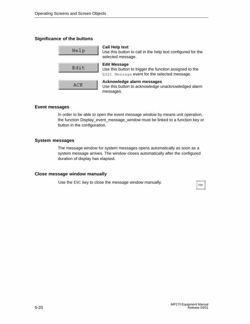
Operating Screens and Screen Objects
5-20MP270 Equipment Manual
Release 03/01
Significance of the buttons
Call Help text Use this button to call in the help text configured for theselected message.
Edit Message Use this button to trigger the function assigned to theEdit Message event for the selected message.
Acknowledge alarm messages Use this button to acknowledge unacknowledged alarmmessages.
Event messages
In order to be able to open the event message window by means unit operation,the function Display_event_message_window must be linked to a function key orbutton in the configuration.
System messages
The message window for system messages opens automatically as soon as asystem message arrives. The window closes automatically after the configuredduration of display has elapsed.
Close message window manually
Use the ESC key to close the message window manually.
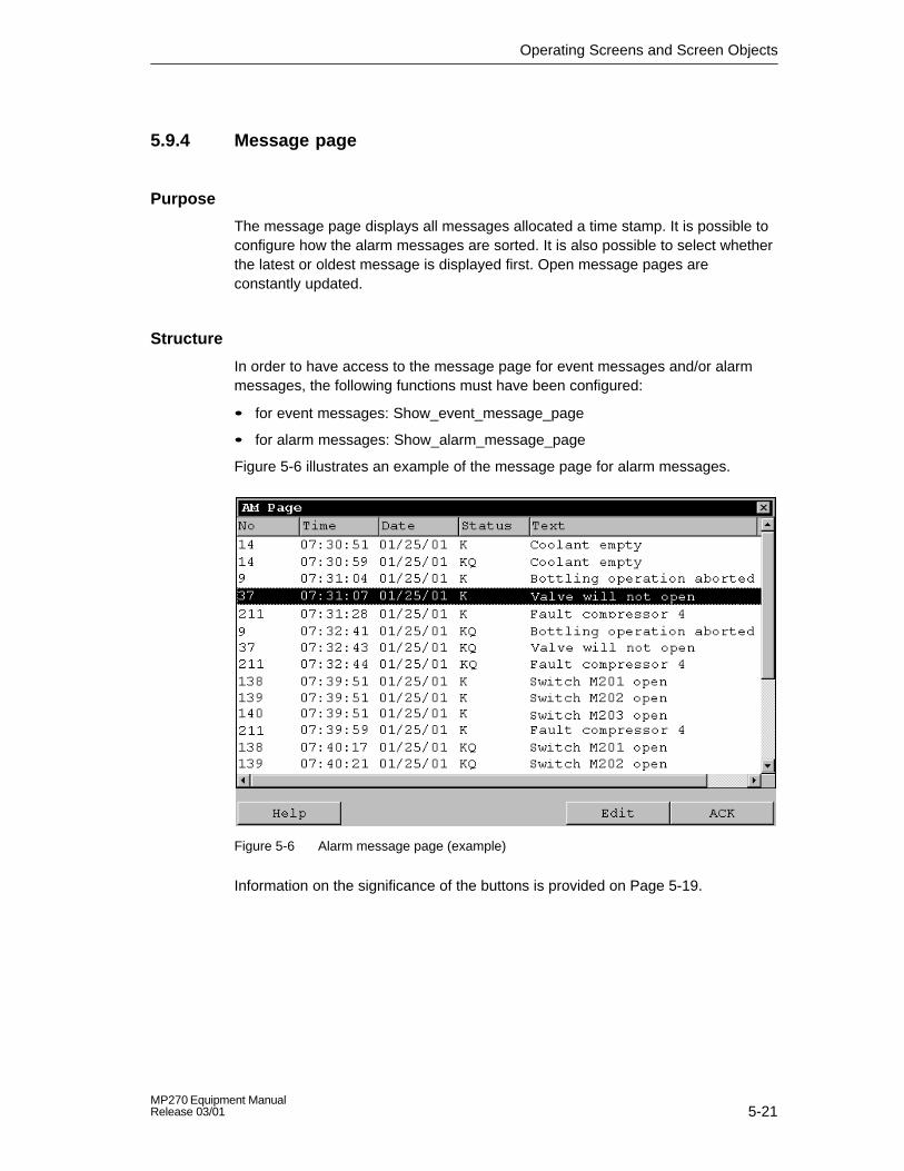
Operating Screens and Screen Objects
5-21MP270 Equipment ManualRelease 03/01
5.9.4 Message page
Purpose
The message page displays all messages allocated a time stamp. It is possible toconfigure how the alarm messages are sorted. It is also possible to select whetherthe latest or oldest message is displayed first. Open message pages areconstantly updated.
Structure
In order to have access to the message page for event messages and/or alarmmessages, the following functions must have been configured:
� for event messages: Show_event_message_page
� for alarm messages: Show_alarm_message_page
Figure 5-6 illustrates an example of the message page for alarm messages.
Figure 5-6 Alarm message page (example)
Information on the significance of the buttons is provided on Page 5-19.

Operating Screens and Screen Objects
5-22MP270 Equipment Manual
Release 03/01
5.9.5 Message buffer
Purpose
The message buffer displays all message events allocated a time stamp. It ispossible to configure how the alarm messages are sorted. It is also possible toselect whether the latest or oldest message is displayed first. Open messagebuffers are constantly updated.
Structure
In order to have access to the message buffer for event messages and/or alarmmessages, the following functions must have been configured:
� for event messages: Show_event_message_buffer
� for alarm messages: Show_alarm_message_buffer
Figure 5-7 illustrates an example alarm message buffer.
Figure 5-7 Alarm buffer (example)
Information on the significance of the buttons is provided on Page 5-19.

Operating Screens and Screen Objects
5-23MP270 Equipment ManualRelease 03/01
5.9.6 Message view
Purpose
Certain views are defines for messages which are queued or still to beacknowledged or for message events in the message buffer (volatile or archive) inthe message indicator. Various filter criteria are available in ProTool CS for thispurpose.
Structure
The message view (Figure 5-8) displays messages that are queued on the MP270or still have to be acknowledged. The message view can be used to acknowledgethe messages.
The message view can also be used to display a history of message events.
Figure 5-8 Example of a message view
Significance of the buttons
Call Help text
Use this button to call in the help text configured for theselected message.
Edit Message
Use this button to trigger the function assigned to theEdit Message event for the selected message.
Acknowledge alarm messages
Use this button to acknowledge unacknowledged alarmmessages.

Operating Screens and Screen Objects
5-24MP270 Equipment Manual
Release 03/01
Message categories
In order to be able to distinguish between the different message categories, theyare marked in the first column of the message view:
! Alarm messages
Empty Event messages
$ System messages
S7 S7 messages
5.9.7 Simple message view
Purpose
A simple message view provides a subset of the functionality of a message view(Page 5-23). This provides a simple method with which, for example, to create amessage line to display event and system messages in a screen.
Structure
The figure below provides an example of a simple message view with the followingcolumns configured:
� Date
� Time
� Message number
� Message states
� Message text
25.01.01 14:27:06 110001 K Change to operating status ’online’
25.01.01 14:27:07 140001 K Connection discontinued: Station 2, Rack 0, Slot 0

Operating Screens and Screen Objects
5-25MP270 Equipment ManualRelease 03/01
5.10 Bar Graphs
Purpose
Bar graphs present a value in the form of a rectangular area. The MP270 thusprovides a clear indication of how far the current value is from the limit values, or ifa setpoint value has been reached, at a glance. Bar graphs can be used to displayfill levels or quantities, for example.
Display
It is possible to configure minimum and maximum values and the direction bargraph moves by increasing the tag value:
Figure 5-9 depicts the various states of a horizontal bar graph:
1. Value drops below the minimum value configured
2. Value lies within the configured display range
3. Value exceeds the maximum value configured
4. Value lies within the configured limit range
Figure 5-9 Different bar states

Operating Screens and Screen Objects
5-26MP270 Equipment Manual
Release 03/01
5.11 Trend View
Purpose
The trend view is a particularly clear form of displaying process data in acontinuous manner. In the case of processes that only change slowly, the trendview can visualize events that have already occurred and provides access to, andestimate of trends in the process sequence. On the other hand, data issuedconcerning processes which run quickly can be easily evaluated using this form oftrend view.
Configurable properties
A number of different trends can be displayed simultaneously in the trend view.The following properties are among those which can be configured for a trendgraphic:
� Trend type: Realtime trend or History trend
� Triggering: Cycle triggering or Bit triggering
� Limit values:The MP270 displays the points at which configured limit values are reached orexceeded by changing the color of the trend view.
Structure
Figure 5-10 illustrates an example of a trend view with a realtime trend and buttonsconfigured for navigating within the trend.
Figure 5-10 Operable trend view (example)
Navigation using buttons
It is possible to navigate through the trend using the configured buttons. Theindividual buttons have the following significance:

Operating Screens and Screen Objects
5-27MP270 Equipment ManualRelease 03/01
Button Significance
Start/Stop updateInterrupts the current updating process for the trend untilthe button is pressed again.
Back to start Scrolls back to the start of the trend recording.
ScrollShifts the trend section half a window width to theleft/right.
Zoom in/outsection
Expands/compresses the trend view horizontally.
Navigation using the keyboard
If no buttons are configured for the trend view, use the MP270 keyboard tonavigate through the trend. A condition for this is that the configuration supportsnavigation using the keyboard.
Keys Significance
Back to start Scrolls back to the start of the trend recording.
Scroll back Shifts the trend curve section half a window width to theleft .
Scroll forward Shifts the trend section half a window width to the right.
Zoom section Expands the trend horizontally.
Reduce section Compresses the size of the trend horizontally.
Notice
It is not possible to interrupt the updating of the trend using the keyboard.
Display archive data as a trend
If data stored in an archive is displayed in the trend view, it is represented ashistory trends, i.e. the trend data is read out of the archive and displayed accordingto events. Application for trends of this kind are power-on processes ortemperature patterns on heating up an oven.
The trend view is not updated when the archive data changes.

Operating Screens and Screen Objects
5-28MP270 Equipment Manual
Release 03/01
5.12 Slider Control
Purpose
Use a slider control to enter and display numerical values in analog form. To entervalues, move the slider to the required position. When used as a display element,the value is represented by the position of the slider.
Function
The slider control is linked to a tag. On moving the user-controlled slider, thecorresponding value is written to the tag. Conversely, when the tag value ischanged, the position of the moving slider is changed correspondingly, unless itbeing moved by the operator at that moment.
Display
The figure on the right illustrates an example of a slider forsetting and displaying temperature values. The current value(in this case: 50) appears as plain text and as a bar graph.
Operation
In order to operate the slider, select it using a cursor key, forexample. Use the following keys to actually move the slider:
Significance Keys
Increase value continually
Decrease value continually
!Caution
In the following cases, it is possible that the value indicated by the slider controldiffers from the real value of the related tag:
The value range configured for the password protected slider control (minimumand maximum values) does not correspond with the limit values configured for theslider control tag.

Operating Screens and Screen Objects
5-29MP270 Equipment ManualRelease 03/01
5.13 Analog Display
Purpose
An analog display indicates numerical values as a pointer instrument.
Function
The analog display is linked to a tag. When the tag value changes, the pointerposition changes correspondingly. The display can be configured to include anon-return pointer. At runtime, the non-return pointer indicates the maximum valuereached so far by the value being displayed. It is reset when the current window isopened.
The analog display is purely a display element. It cannot be used to enter valueson the MP270.
Display
Figure 5-11 illustrates an example of an analog display indicating temperatures.
Figure 5-11 Example of a typical analog display
Note on instrument scaleAny color-code differentiations configured for various scale ranges are notdisplayed on the MP270.

Operating Screens and Screen Objects
5-30MP270 Equipment Manual
Release 03/01
5.14 Date/Time
Purpose
The screen object Date/Time displays the current values for the time and/or date.The time can be modified online if the corresponding feature is configured.
The calendar date and time values are synchronized with the system values in theoperating system. The MP270 accesses these values, for example, to assign timestamps to message events.
Notice
Without the optionally available backup battery (Chapter 11), the MP270 onlystores the system time for a few hours1). If the unit is disconnected from the powersupply for a longer period, the date and time must be updated followingrecommissioning.
1) The unit must have been in operation for approx. 6–8 hours, without any interruptions,beforehand.
Format
The format of the date and time depends on the language currently set. Itcorresponds to the standard international conventions:
Table 5-1 Examples of language-dependent formats for Date/Time
Language Example
Date Timelong short
German Samstag, 25. November 2000 25.11.00 12:59:32
English (USA) Saturday, November 25, 2000 11/25/00 12:59:32 PM
French samedi 25 novembre 2000 25/11/00 12:59:32
Italian sabato 25 novembre 2000 25/11/00 12.59.32
Spanish(traditional)
sábado 25 de novembre de 2000 25/11/00 12:59:32
The format for date and time can be modified in the Control Panel. To do so,select the icon depicted on the right.
Information on opening the Control Panel is provided on Page 8-5.

Operating Screens and Screen Objects
5-31MP270 Equipment ManualRelease 03/01
Notice� When entering the date and time, ensure that the two values are separated by
a space.
� If the operating system does not support the language set on the operatingunit, the language predefined for the operating system is used.
Synchronizing date/time with the PLC
The date and time in the MP270 and PLC can be synchronized if this feature isdefined in the configuration and PLC program. To do this, the PLC jobs 14 (SetTime) and 15 (Set Date) are provided. Use PLC jobs 40 and 41 to transfer the dateand time from the MP270 to the PLC.
Further information on this is available in the Communication for Windows-basedSystems user’s manual.

Operating Screens and Screen Objects
5-32MP270 Equipment Manual
Release 03/01
5.15 Digital/Analog Clock
Purpose
The digital/analog clock provides the option of displaying the system time innumbers (digital) or as a clock with hands (analog). The digital display alsoincludes the current date. The display format is language dependent. It is based onthe format defined by the MP270 operating system.
Display
The digital/analog clock is purely a display element. This means that the date andtime cannot be set using the MP270. In order to set the date and time, use theDate/Time screen object (refer to Page 5-30).
Figure 5-12 illustrates an example of a configured analog clock.
Figure 5-12 Example of a typical analog clock

Operating Screens and Screen Objects
5-33MP270 Equipment ManualRelease 03/01
5.16 Password List
Purpose
While the system is being configured using ProTool CS, operating elements can beprotected against unauthorized use by means of passwords. Important parametersand settings can then only be modified by authorized personnel.
Password hierarchy
Hierarchically defined password levels from 0 to 9 exist for password protectionpurposes. When a password is assigned to an individual user or to a whole usergroup, the permission to execute functions at a specific level is assignedsimultaneously. If, for example, a user is assigned to password level 4, he or she isauthorized to execute functions of password levels 0 to 4.
Password level
Password level 0:This minimum password level is assigned to functions that have no, or only aminimal effect on the course of the process. In order to trigger functions assignedto Password Level 0, no password needs to be entered.
Password levels 1 to 8:Functions are assigned to levels 1 to 8 according to their increasing importance.Before triggering a function with a password level greater than 0, the MP270requests the corresponding password to be entered.
Password level 9Only the supervisor (system support specialist or service technician) is grantedauthorization to execute functions assigned to password level 9. The superuserhas access to all the MP270 functions.
Logging in on the MP270
After calling a function protected by a password, the MP270 automatically requeststhe entry of a password. Once entered, the password need not be entered again inorder to call in other functions of this password level or lower.
When correspondingly configured, it is also possible to log in on the MP270 via aninput field for confidential password entry (Page 5-9). The character stringentered is represented by placeholders (*).

Operating Screens and Screen Objects
5-34MP270 Equipment Manual
Release 03/01
Logging off from the MP270 (logout)
In order to rule out operation by unauthorized personnel, a password level greaterthan 0 should not remain active on the MP270 over too long a period of time. Thefollowing options are available to explicitly reset passwords levels:
� Configured logout time expiresIf the MP270 is not operated within the period of time configured (logout time),the current password level is automatically reset to 0.
� Manual logoutIf the function Logoff_user is linked to an operating element in the configuration,it can be used to reset the current password level to 0.
TipIt is also possible to reset the current password level to 0 by entering anincorrect password.
5.16.1 Password management
Purpose
Individual users can be entered in a password list on the MP270 and assigned apassword level according to specific responsibilities. When processing the list,conclude each field entry by pressing the Enter key . The password list contains allthe passwords configured on the MP270. The list is coded and stored on theMP270, protected against a power failure.
Figure 5-13 illustrates an example of a password list with six entries.
Figure 5-13 Example of a password list
View password list
Only those passwords are displayed which have a password level equal to or lowerthan that with which the user is currently logged in. The MP270 displays thepassword list entries in alphabetic order.

Operating Screens and Screen Objects
5-35MP270 Equipment ManualRelease 03/01
Creating a password
The user can only edit the password list up to the level with which he is currentlylogged in. All passwords used in the system must be unique. It is not possible toassign the same password to different password levels. However, there are norestrictions in assigning different passwords to the same password levels.
Deleting a password
To delete a password from the password list, overwrite the password levelassigned to it with 0.
5.16.2 Export/Import password list
Purpose
If a system includes several operating units which are accessed by the sameusers, the same passwords must be installed on each operating unit. In order thatthe password list need not be re-entered on each operating unit, it can be createdon one unit and then exported and imported on other units.
Condition
In order to be able to export/import password lists on the MP270, the functionImport_Export_Passwords must be linked to a button or function key, for example.The file name of the password list to be exported/imported must be specified asthe function parameter during configuration.
Notice
� The password list is coded. It cannot be edited with external tools.
� Do not export a password list directly after it has been modified. Exit the screenobject Password List after changing it and wait with the export function untilmodifications have been written in the internal Flash memory.

Operating Screens and Screen Objects
5-36MP270 Equipment Manual
Release 03/01
5.17 Status/Force
Purpose
The MP270 can be used to access the connected PLC and periphery to read andwrite values. PLC program operands can be monitored and modified easily withouthaving to connect an additional programming unit or PC to the PLC.
This option is particularly useful during the testing and commissioning phase of theconfiguration.
Condition
The following conditions must be fulfilled in order to be able to access values in thePLC directly from the MP270:
� The connected PLC is a SIMATIC S5 or SIMATIC S7
� The configuration must contain the screen object Status/Force (Figure 5-14)
Structure
Figure 5-14 illustrates the basic structure of the screen object Status/Force. Eachline represents an operand.
Figure 5-14 Status/Force: Example for SIMATIC S7
The table indicates the significance of the individual columns and buttons.
Column/Button Significance
Connection Select the PLC whose address area is to be displayedand/or modified.
Type, DB number, Offset, Bit Specify the address in this column.
Data type, Format This column is used to change the format of the output.

Operating Screens and Screen Objects
5-37MP270 Equipment ManualRelease 03/01
SignificanceColumn/Button
Status value The MP270 uses this column to display the values of theoperands read from the PLC.
Force value Use this column to enter the values to be written to theoperands.
This button is used to update the display in the columnStatus value.
The button is locked after being pressed. None of theinput fields can then be used until the button is pressedagain, thus stopping the update.
This button is used to apply the new value specified in thecolumn Force value. The value is then written to the PLC.
Operation
The table lists the key combinations for operating the Status/Force screen object:
Keys Significance
Operate button Write.
Operate button Read.
Select first/last field in current line.
Select first/last field in current column.
Increase width of current column.
Reduce width of current column.
Delete current line.
Alternatively:Do not select a PLC from the Connection column.
Optimize column width.
Open selection field.

Operating Screens and Screen Objects
5-38MP270 Equipment Manual
Release 03/01

6-1MP270 Equipment ManualRelease 03/01
Recipes
6.1 Overview
PurposeThe purpose of recipes is to transfer of quantities of related data together andsynchronously from the MP270 to the PLC and vice versa.
Principles of operation
Using the example of the filing cabinet (Figure 6-1), the two terms Recipe and DataRecord should be defined because they are important for subsequentunderstanding of the process.
Fruit juice plant
Grapefruit
Lemon
Orange
Drink
NectarJuice
Apple
Figure 6-1 Recipe and Data Record, using a filing cabinet as an analogy
6

Recipes
6-2MP270 Equipment Manual
Release 03/01
� RecipeRecipes correspond to the individual drawers if the filing cabinet illustrated (e.g.grapefruit or lemon). The reference value fields (tags) belonging to the particularrecipe are defined in each drawer. The recipes define the data structure inProTool CS. This structure cannot be subsequently modified on the MP270.
� Data recordData records correspond to the filing cards in the individual drawers of thecabinet (e.g. Drink, Juice and Nectar). A data record contains the values for arecipe. Data records are created, modified and deleted on the MP270. The datarecords are also stored on the MP270. This saves storage space o the PLC.
The Import/Export function provides the additional option of using external toolsto edit exported data records and then reimporting them on the MP270.
Example of a recipe
An example for use of a recipe is its application on a filling station of a fruit juicesystem. The same filling station is used to produce orange drink, orange juice andorange nectar. The mixing ratios are different for each product. The ingredients arealways the same.
Assume that a recipe called Mixture is created, which has the following datastructure:
Tag Name
Var_2 l orange
Var_3 l water
Var_4 kg sugar
Var_5 g flavor
The designations l Orange, g Aroma etc. of the tags are the so called entrynames. The entry names are also displayed on the MP270. In this way, forexample, the tag Var_2 can be identified as the tag designating the mixturecomponent Orange.
The data records contain the values for the different drink types. The data records
may appear as follows, for instance:
Orange drink Orange juice Orange nectar
l orange 90 l orange 95 l orange 70
l water 10 l water 5 l water 30
kg sugar 1.5 kg sugar 0.5 kg sugar 1.5
g flavor 200 g flavor 100 g flavor 400

Recipes
6-3MP270 Equipment ManualRelease 03/01
6.2 Recipe Configuration
Basic procedure
The basic steps to configuring a recipe are listed below:
1. Define the structure of the recipe:Assign tags to the recipe structure. These tags are provided with entries fromthe data records.
Define a name for the recipe. This name is used to select the recipe in theconfiguration and on the MP270.
2. Set recipe tag propertiesThe following options can be configured in ProTool CS:
– Synchronize tags This option defines that the data from a data record has been read from thePLC or data medium and written in the tag or read from the tags configuredfor the recipe. This establishes a connection between the tags configured inthe recipe and the tags in the screens. When a data record is loaded, thevalues are written to the tags used in the screens.
– Tags offline If this option is also activated, the values entered are only stored in the tags,and not transferred to the PLC. Otherwise, values entered are transferreddirectly to the PLC.
3. Define storage location for data records on the MP270The data storage location for data records can be configured. The followingsettings are possible:
Storage location Setting in ProTool CS
Internal Flash memory \Flash\...
Memory card
� PC card
� CF card
� \Storage Card\...
� \Storage Card2\...
Network Any path in the network, e.g.\\PC_Name\... (target computer)
Caution
Cyclical writing access is not permitted for the internal Flash memory because itreduces the service life of the Flash memory and thus the service life of the unit.Use an external memory card instead.

Recipes
6-4MP270 Equipment Manual
Release 03/01
4. Set download synchronization
It is possible to configure whether the data records are downloaded to the PLCwith or without synchronization.
5. Creating a recipe screenConfigure one or more screens in order to create, store and download datarecords on the MP270.
Notice
If tags are configured for recipe and data record numbers, the values for the datarecord are neither loaded nor displayed in the recipe view when the recipe displayis opened. As soon as a data record is selected in the recipe view the currentvalues are transferred from the data record memory into the recipe tags.
Further information
Detailed information on how to create a recipe is provided in the online help to theProTool CS configuration software and in the ProTool Configuring Windows-basedSystems user’s guide.
System limits
The table provides an overview of the system limits for recipes.
Elements Number
Number of recipes 100
Data records per recipe Limited by storage medium
Entries per recipe 500
Total number of entries 5,000

Recipes
6-5MP270 Equipment ManualRelease 03/01
Memory requirements for data records
The memory requirements per recipe (in kByte) is calculated from the threesummands D1 + D2 + D3.
D1 = [(no. of entries x 20) + 4] : 1024D2 = [(no. of data records x 12) + 4] : 1024D3 = [no. of data records x (data record length + N) + 4] : 1024
D1, D2 and D3 are rounded up to the next whole number.
A data record length is the sum of all the tag lengths configured for the data recordin bytes. For example, a tag of the type FLOAT has a length of 4 byte.
The following applies for N:
Data record name < 13 characters: N = 12Data record name > 12 characters: N = 40
Notice
The internal Flash memory has a maximum storage capacity of 64 kByte.
Tip:In the interest of optimizing the service life of the unit and achieving a betterperformance, use either the network or an external memory card to store datarecords.

Recipes
6-6MP270 Equipment Manual
Release 03/01
6.3 Editing Data Records
In this chapter
This chapter provides information on how to edit data records on the MP270. Thefollowing information is also included:
� Layout of the recipe view (Page 6-7)
� Displaying data records (Page 6-10)
� Creating new data records (Page 6-10)
� Copying data records (Page 6-11)
� Modifying data records (Page 6-12)
� Renaming data records (Page 6-13)
� Deleting data records (Page 6-13)
� Reading data records from the PLC (Page 6-14)
� Downloading data records to the PLC (Page 6-14)
� Editing data records in recipe screens (Page 6-15)
� Functions and PLC jobs (Page 6-17)
� Exporting/Importing data records (Page 6-18)
� Exporting, editing and importing data records (Page 6-20)
� Response following modification of recipe structure (Page 6-21)
Methods
Data records can be edited on the MP270 either in tables or screens:
� Tabular editingThe recipe view is available for the tabular editing of data records (Page 6-7).The recipe view enables recipes and data records to be handled in anuncomplicated, quick way.
It is typically used to edit data records of smaller recipes. Values entered on theMP270 are not directly transferred to the PLC when entered.
� Editing in recipe screensThe project engineer can use recipe screens (Page 6-15) to customize the userinterface for editing data records and, for example, simulating the systemvisually, providing graphics and individual masks for entering data records.
This method is typically used for processing medium and large data recordsoffline in the recipe view. The values entered on the MP270 are only saved inthe tags, but not transferred directly to the PLC on input.

Recipes
6-7MP270 Equipment ManualRelease 03/01
6.3.1 Recipe view
Purpose
The recipe view is typically used to edit recipe data records in tabular form. Thisprovides an uncomplicated method of displaying, creating, copying, modifying,deleting and downloading data records on the MP270.
All descriptions on editing data records provided in this Chapter 6.3.1 relates purelyto the use of the recipe view. Information on editing data records in recipe screensis provided on Page 6-15.
Display
Figure 6-2 illustrates an example of the layout of the recipe view. Some of theoperating and display elements can be configured so that they are faded out on theMP270.
Figure 6-2 Layout of the recipe view (example)

Recipes
6-8MP270 Equipment Manual
Release 03/01
Significance of the operating and display elements
No. Function
Select recipeIf the corresponding function is enabled in ProTool CS, it is possible toselect a configured recipe in this selection field. The number of theselected recipe is displayed to the right of the selection field. Thisnumber is only relevant during the configuration. It cannot be modifiedon the MP270.
Select data recordAs soon as a recipe has been selected, the data records available aredisplayed in this field. In addition, the data record number is displayed tothe right. The number field only becomes active when the input of a datarecord number is permitted, e.g. after changing the data record numberor creating a new data record.
View /Edit entriesThis table contains all the entries which are configured in the selecteddata record. Sorting complies to the configured sequence. Theright-hand column displays the associated values.
The entry names cannot be edited on the MP270.
Create new data recordThis button initiates the creation of a new data record. Thesetpoint values are predefined with default values configured asstart values for the respective tags.
Key combinations:
Save data recordThis button is used to save the current values of the date recorddisplayed on the MP270 data medium. The memory location isdefined in ProTool CS.
The data record is stored under the currently defined name andnumber.
Key combinations:
Delete data record
This button is used to delete the data record currently displayedfor the defined recipe from the MP270 data medium.
Key combinations:
Read data record from the PLCThis button is used to read the data record related to thecurrently set recipe from the PLC and display the values on theMP270.
Key combinations:

Recipes
6-9MP270 Equipment ManualRelease 03/01
FunctionNo.
Write data record in the PLC
This button is used to write the current data record values in thePLC.
Key combinations:
Status bar
The MP270 displays the status of the current operation in this line, e.g.Downloading.
!Caution� If the two options Synchronize Tags and Tags Offline are activated in the
configuration, the values from the table are applied when values in the tablesand screens are changed simultaneously.
� If the data record currently being edited in the recipe view is changed in thebackground (e.g. by means of a PLC job), the recipe view is not automaticallyupdated.
Tips on operating the recipe views
� Quick selection of recipes and data records
When the selection field is opened up, enter the first letter of the recipe or datarecord to be selected to access the relevant area of long lists, thus speeding upthe selection procedure.
� Edit entriesIf the value marked in the recipe view is to be modified, it is initially deleted bypressing one of the alphanumeric keys. This occurs with regard to all listelements in Windows. In order to prevent this, proceed as follows:
– After selecting the value to be changed, press the Enter key.
– Move the text cursor to the relevant position by pressing the cursor key orSHIFT and cursor key.
– Insert the modifications.
– Confirm the changes, e.g. by pressing the Enter key.

Recipes
6-10MP270 Equipment Manual
Release 03/01
Displaying data records
Proceed as follows to display data records on the MP270 data medium:
Step Procedure
1 Select recipe Step 1 is only possible when recipe selection has beenconfigured.
� Select the selection field for the configured recipes (Position1 in the figure on Page 6-7).
� Open the selection field and mark the required recipe in theopened selection list.
� Confirm the selection.
2 Select data record � Select the selection field for the existing data records(Position 2 in the figure on Page 6-7).
� Open the selection field and mark the required data record inthe opened selection list.
� Confirm the selection.The selected data record is loaded. The configured entriesare displayed in table form with name and setpoint value.
Creating new data records
Proceed as follows to create new data records on the MP270:
Step Procedure
1 Select recipe � Select the required recipe, as described in Step 1 onPage 6-10.
2 Create data record � Press the key depicted on the left.
The name and number of the data record displayed aredeleted. The entries in the table are assigned the configuredstart values.
3 Enter data recordname
� Enter a new data record name in the selection field for datarecords (Position 2 in the figure on Page 6-7).
� After entering the data record name, the next free datarecord number is automatically entered on the right. Thisnumber can be changed, if necessary.
4 Change values � Enter a setpoint value for each entry configured in the table(Position 3 in the figure on Page 6-7).
5 Save data record � Press the key depicted on the left.
The new data record is written on the data medium.
The MP270 responds with a system message if the name ornumber entered already exist. The writing process is notexecuted in this case.

Recipes
6-11MP270 Equipment ManualRelease 03/01
Storage location for new data records
The data storage location for the new data record can be configured. The followingsettings are possible:
� Internal Flash memory
� Memory card
– PC card
– CF card
� Any path in the network, if configured (refer to Page 8-9)
Copying data records
In order to copy data records, save them under new names. Proceed as follows:
Step Procedure
1 Select recipe anddata record
� Select the required recipe and the data record to be copiedas described in Steps 1 and 2 on Page 6-10.
2 Enter data recordname
� Enter a new data record name in the selection field for datarecords (Position 2 in the figure on Page 6-7).
� After entering the data record name, the next free datarecord number is automatically entered on the right. Thisnumber can be changed, if necessary.
3 Save data record � Press the key depicted on the left.
The new data record is written on the data medium.
The MP270 responds with a system message if the name ornumber entered already exist.

Recipes
6-12MP270 Equipment Manual
Release 03/01
Changing data records
Proceed as follows to change existing data records:
Step Procedure
1 Select recipe anddata record
� Select the required recipe and the data record to be changedas described in Steps 1 and 2 on Page 6-10.
2 Change values � Change the setpoint value in the table (Position 3 in thefigure on Page 6-7).
The entry names cannot be edited on the MP270.
3 Save data record � Press the key depicted on the left.
The modified data record overwrites the original data recordon the data medium.
Notice
If large-scale modifications have been carried out in recipes in ProTool CS and,after downloading the modified project, the data records on the MP270 datamedium deviate a great deal from the original recipe structure, it is recommendedto:
� reorganize the data medium: Export the data records, delete the files with the prefix PTRCP_1) from the datamedium and import the data records again
or
� delete the files with the prefix PTRCP_1) from the data medium: In this case, use Windows Explorer. (Note: After the files have been deleted, the relevant data must be re-entered)
In this way, all the tags no longer used are deleted.
1) If necessary, only delete the files of the modified recipes

Recipes
6-13MP270 Equipment ManualRelease 03/01
Renaming data records
Proceed as follows to rename existing data records:
Step Procedure
1 Select recipe anddata record
� Select the required recipe and the data record to be copiedas described in Steps 1 and 2 on Page 6-10.
2 Enter data recordname
� Enter a new data record name in the selection field for datarecords (Position 2 in the figure on Page 6-7).
� After entering the data record name, the next free datarecord number is automatically entered on the right. Resetthis number to its original value.
3 Save data record � Press the key depicted on the left.
The data record is written on the data medium under the newname.
The MP270 responds with a system message if the name ornumber entered already exist.
Deleting data records
Proceed as follows to delete data records on the MP270:
Step Procedure
1 Select recipe anddata record
� Select the required recipe and the data record to be changedas described in Steps 1 and 2 on Page 6-10.
2 Delete data record � Press the key depicted on the left.
The data record is deleted from the data medium afterconfirming a confirmation request.

Recipes
6-14MP270 Equipment Manual
Release 03/01
Reading data records from the PLC
Proceed as follows to update data records in the MP270 working memory withvalues from the PLC:
Step Procedure
1 Select recipe � Select the required recipe, as described in Step 1 on Page6-10.
2 Read values � Press the key depicted on the left.
� The current values are read from the PLC and displayed.
3 Edit data records � The data can then be edited, e.g. values modified, saved,downloaded to PLC, etc.
The MP270 responds with a system message if downloadingfrom the PLC is not possible because, in cases wheresynchronization with the PLC is configured, for example, thedata mailbox is currently locked.
Downloading data records to the PLC
In order that a modified or new data record can take effect in the PLC, it must bedownloaded to the PLC.
Proceed as follows to download data records to the PLC:
Step Procedure
1 Select recipe anddata record
� Select the required recipe and the data record to bedownloaded as described in Steps 1 and 2 on Page 6-10.
2 Write values � Press the key depicted on the left.
The values are written in the PLC.
The MP270 responds with a system message if downloadingfrom the PLC is not possible because, in cases wheresynchronization with the PLC is configured, for example, thedata mailbox is currently locked.
Recipes
6-15MP270 Equipment ManualRelease 03/01
6.3.2 Recipe screens
Purpose
Recipe screens are typically representations of the system. The screens providedisplay and operating elements with which to create, save, modify, delete anddownload data records. Large recipes can be split into several topic-specificscreens and clearly displayed, e.g. with graphic elements.
Components for editing data records
In order to be able to edit data records in recipe screens on the MP270 thecorresponding components, e.g. input/output fields and functions, must beconfigured:
� Recipe view: Recipe screens can contain a recipe view (Page 6-7) not only to enable theeasy selection of recipes and data records but also for editing data records. Theconfigured functional scope of the recipe view can vary, according to theintended purpose.
Information on editing data records in recipe screens is provided on Page 6-7.The instructions stipulated there generally also apply for editing data records inrecipe screens. However, in this case, input is performed in the screens.
� Functions:Depending on whether a recipe view is configured in the project or not, and onthe properties assigned to it, there are various functions available to transferdata records between MP270 and PLC, e.g.:
– Load_Data_Record
– Save_Date_Record
– Data_Record_PLC_to_Tags
– Data_Record_Tag_to_PLC
Further functions for data records:
– Delete_Data_Record_Memory
– Change_Data_Record_Number_To_Name
More functions and PLC jobs, which are linked to the downloading of data records,are described on Page 6-17.
Editing data records offline
The way in which data records are edited on the MP270 s defined duringconfiguration. It is typically used for the offline editing of data records in recipescreens. Values entered on the MP270 are not directly transferred to the PLC whenentered.
Proceed as follows to edit data screens in recipe screens offline:

Recipes
6-16MP270 Equipment Manual
Release 03/01
Step Procedure
1 Select a data record.
2 Trigger reading of the selected data record from the storage medium:
� With recipe viewIt is automatically loaded on selecting the data record.
� Without recipe viewActivate the operating element linked with the Load_Data_Record function.The function parameters must have been set accordingly beforehand.
3 The data of the data record is written to the tags.
4 Edit the tags using the configured input/output fields.
5 Save the modified tags.
� With recipe viewClick the Save button. If necessary, you must first specify a new name.
� Without recipe viewActivate the operating element linked with the Save_Date_Record. Thefunction parameters must have been set accordingly beforehand.
Editing data records online
In order to edit data records online, the option must either be defined duringconfiguration or the Recipe_Tags_Online_Offline function defined in theconfiguration. In the case of online editing, the values entered are transferreddirectly to the PLC. This method is normally used when commissioning themachine/system in order to test, run-up and position.
Proceed as follows to edit data records on the MP270 online:
Step Procedure
1 Select a data record.
2 Trigger reading of the selected data record from the storage medium:
� With recipe viewIt is automatically loaded on selecting the data record.
� Without recipe viewActivate the operating element linked with the Load_Data_Record function.The function parameters must have been set accordingly beforehand.
3 The data of the data record is written to the tags and thus also to the PLC.
4 Edit the tags using the configured input/output fields. This will simultaneouslychange the values in the PLC as well.

Recipes
6-17MP270 Equipment ManualRelease 03/01
ProcedureStep
5 Save the modified tags.
� With recipe viewClick the Save button. If necessary, you must first specify a new name.
� Without recipe viewActivate the operating element linked with the Save_Date_Record. Thefunction parameters must have been set accordingly beforehand.
!Warning
When editing data records online, the entered values are transferred to the PLCwithout synchronization. Therefore, when changing individual values, ensure thatno impermissible operating statuses occur in the machine/system.
6.3.3 Functions and PLC jobs
Functions
The following functions can be used to import and export recipe data records forediting with external tools:� Export_Data_Records � Import_Data_Records
They can be used to either import and export either individual data records or alldata records in a recipe, according to the configured parameters.
The following functions can be used to transfer data records between the PLC andMP270 data medium.� Data_Record_DAT_to_PLC � Data_Record_PLC_to_DAT
The data medium is either the internal Flash memory, the memory card or, ifconfigured, any network path (refer to Page 8-9). Both the recipe and data recordmust be specified as parameters in which the values should be written.
PLC jobs
The following two PLC jobs can be used to transfer data records between the PLCand MP270 automatically:� No. 69: “SPS → DAT” (read data record from PLC)� No. 70: “DAT → SPS” (write data record in PLC)
Information on PLC jobs is provided in the Communication for Windows-basedSystems User’s Guide.

Recipes
6-18MP270 Equipment Manual
Release 03/01
6.3.4 Import/Export data records
Purpose
When the appropriate features have been configured, data records on the MP270can be exported as CSV files to the data medium. This feature can be used to editdata records with external tools, e.g. with a spreadsheet program or text editor andimport them on the MP270 again.
Condition
In order to export and import data records during runtime, the configuration mustcontain the following functions:
� Export_Data_Records
� Import_Data_Records
These functions must be linked in the ProTool CS configuration software, e.g. to afunction key or button.
File format CSV
With file format CSV, the table columns (entry name and value) are separated by aseparator (e.g. semicolon). Each table row (entry) is terminated by a line feed.
The example in Figure 6-2 (Page 6-7) appears as follows in CSV format for theindividually exported data record Juice:
Orange;Juice
3;2
Var_2;95
Var_3;5
Var_4;0.5
Var_5;100
Additional information is stored in the first two lines:
� Line 1: Name of the recipe and data record
� Line 2: Number of the recipe and data record
The MP270 interprets the information on importing the file.
Notice
When the CSV files are edited with an external text editor, the modifications aresaved in text format (without control codes).

Recipes
6-19MP270 Equipment ManualRelease 03/01
Export/Import all data records in a recipe
When appropriately configured, all the data records in a recipe can beimported/exported together. The CSV file for the example on Page 6-2 thenappears as follows:
Orange;Drink;Juice;Nectar
3;1;2;3
Var_2;90;95;70
Var_3;10;5;30
Var_4;1.5;0.5;1.5
Var_5;200;100;400
Additional information is stored in the first two lines:
� Line 1: Name of the recipe and all the configured data records
� Line 2: Number of the recipe and all the configured data records
The MP270 interprets the information on importing the file.
In this way, the CSV file can be used, for example, to create new data records bymeans of a spreadsheet program (Figure 6-3). After importing the modified file, thenew data records can be used on the MP270.
Figure 6-3 Create data records externally (example: Microsoft Excel)

Recipes
6-20MP270 Equipment Manual
Release 03/01
Exporting, editing and importing data records
Proceed as follows in order to export data records on the MP270 in a CSV file, editit using with an external tool (e.g. spreadsheet program or text editor) and import itback on the MP270:
Step Procedure
1 Export data record � Press the operating element linked with theExport_Data_Records function (e.g. function key or button).
Depending on the parameterization, either all the datarecords are exported to the data medium or only the datarecord defined in the configuration.
The data records are exported in the file which wasconfigured in the parameter File Name in the functionExport_Data_Records.
� Copy the CSV file onto a transferable data medium (e.g.disk) or in a directory which can be accessed by the externaltool.
2 Edit CSV file � Carry out the modifications in the CSV file with an externaltool, e.g. Microsoft Excel or a text editor.
� Save the modifications on the data medium.
� Copy the CSV file back to the original directory.
3 Import datarecords
� Activate the operating element linked with theImport_Data_Records function.
The data records are copied in the data storage areaconfigured for the recipe.
Notice
If data records should be exported and the CSV files edited on a different Windowssystem using a spreadsheet program (e.g. Microsoft Excel), ensure that thedecimal separator and list separator are identical on the two different systems.
These settings can be modified from the Windows Start menu using: Settings → Control Panel → Language on the Numbers tab control (refer to Page 8-7).
The MP270 is supplied with the German language variants set.

Recipes
6-21MP270 Equipment ManualRelease 03/01
6.3.5 Reaction on changing the recipe structure
Standard behavior
The following section describes the standard behavior of the MP270 when itdetects differences between the data record structure stored on the data mediumand the recipe structure currently loaded on the MP270.
Load and export data records, and write in the PLC
� The data record on the data medium contains additional tags:
The values are rejected.
� The data record on the data medium contains values which cannot beconverted to the assigned tag type:
The configured start value for the tag is used.
� Tags are missing in the data record on the data medium:
The configured start value for the tag is used.
!Warning
The assignment is lost on changing the tag name.
Import data records
� The imported data record contains additional tags:The values are rejected.
� The imported data record contains values which cannot be converted to theassigned tag type:
The configured start value for the tag is used. This occurs, for example, whenthe tag type has been changed in the configuration.
� Tags are missing in the imported data record:The configured start value for the tag is used.
Tip
Export the data record after changing the recipe structure and check the exportedvalues. Please observe the related safety notes provided on Page 6-12.

Recipes
6-22MP270 Equipment Manual
Release 03/01

7-1MP270 Equipment ManualRelease 03/01
Archives
Overview
Process data can be archived on the MP270, i.e. stored permanently andevaluated. The following process data can be archived:
� Tags
� Messages
The properties of an archive, e.g. memory location and archive size, is defined bythe configuration planner in ProTool CS.
Archive file format
Each archive is stored as an individual file. Data is stored in the archive file in CSVformat. This enables archived data to be processed and evaluated using externaltools, e.g. with a spreadsheet program or text editor.
In file format CSV, table columns are separated by a separator (e.g. semicolon).Each table row is terminated by a line feed.
Notice
When the CSV files are edited with an external text editor, the modifications aresaved in text format (without control codes).
Storage location
The memory location for archive files is defined during configuration. Possibletargets are:
� Memory card
� Any path in the network
Caution
The internal FLASH memory is not permissible as the memory location for archivefiles because cyclic archiving reduces the service life of the FLASH memory andthus that of the MP270.
7

Archives
7-2MP270 Equipment Manual
Release 03/01
Archive functions
The following functions are available in the ProTool CS configuration software inorder to be able to work with archives on the MP270:
� Open_archive The connection between the MP270 and archive files is established.
� Close_archive All archive files are closed and the connection between the MP270 and archivefiles is disconnected.
� Start_archive Starts the archiving process in the selected archive.Normally, messages and tags are archived throughout the entire process. Thefunction can be used to start the archiving to the specified archive by pressingan operating element on the MP270 and stopped with the functionStop_archive.
� Stop_archive Stops the archiving process in the selected archive.Normally, messages and tags are archived throughout the entire process. Thisfunction can be used to stop the archiving to the specified archive by pressingan operating element.
� Delete_archive Deletes all the entries in the selected archive.
� Start_sequence_archive Switches from the current archive to the following one. If no sequence archivehas been configured, the function is not executed.
� Archive_tag Archives the status of a tag in the archive configured for the tag. This functioncan be used to trigger the archiving of a tag to the specified archive by pressingan operating element on the MP270. The archive must have been startedbeforehand.
Note on performance
If a network is not used when archiving on the MP270, but an ATA-Flash card isused as the archive data medium instead, the archive memory space available islimited. The archiving performance of a FLASH PC card is also very limited.FLASH modules cannot be read from or written to in fine tracks, as opposed to ahard disk. Each access to a FLASH card requires copying large sectors of theFLASH card which greatly reduces the performance.
For this reason, the MP270 should not be used primarily for the cyclical archivingof data. The MP270 is more suitable for archiving non-cyclically occurring faultstates (alarm and event messages).
The MP270 has not been conceived for archiving tasks with high demands onquantity structure or performance.

Archives
7-3MP270 Equipment ManualRelease 03/01
Examples of performance
The table provide examples for the maximum performance possible:
Task ATA FLASH
Recording rate [in entries per second] 5
View of a message archive (10 messages from 2,000 entries)
12 s
Trend view of a tag archive(300 trend values from 2,000 entries)
15 s
Tip:
The time required for reading and displaying is reduced considerably when severalsequence archives are configured rather than one large cyclic archive. A newsequence archive is recommended following approx. 10,000 entries.
Deactivate MP270 with memory card inserted
Caution
Always terminate the runtime software before switching off the voltage supply inorder to prevent loss of data.
Operate the operating element linked to the Exit_runtime function in theconfiguration. Wait until the MP270 start menu (Figure 3-1, Page 3-7) appears andthen switch off the power supply.
If the voltage supply is inadvertently interrupted during operation, the MP270checks the memory card when the power supply is returned and displays a dialogwindow asking whether defect sectors should be repaired.
Remove memory card
Caution
Before removing the memory card, either use the operating element linked withthe Close_archive function in the configuration or stop the runtime software.Operate the operating element linked to the Exit_runtime function in theconfiguration.
Closing the archive or terminating the runtime software may take several minutes,depending on the size and number of the archives stored.

Archives
7-4MP270 Equipment Manual
Release 03/01

8-1MP270 Equipment ManualRelease 03/01
System Settings
Overview
The general settings, listed below, can be modified on the MP270:
� Language (Page 8-2)
� Operating mode (Page 8-3)
� Screen settings (Page 8-4)
� Settings on Windows CE Control Panel (from Page 8-5)
– Communication
– Date/Time
– Network
– Unit properties
– Language settings
– Printer
� Network operation (Page 8-9)
8

System Settings
8-2MP270 Equipment Manual
Release 03/01
8.1 Set Language
Language-dependent objects
When downloading the configuration from the configuration computer, up to threelanguages can be loaded on the MP270 simultaneously. It is possible to switchbetween the languages, online, at any time and display language-dependentobjects (texts and formats) in other languages.
The following are language-dependent, for example
� Messages
� Screens
� Text lists
� Help texts
� Date/Time
� Decimal separating character
Condition
In order to change languages on the MP270 while it is in operation, the followingconditions must be fulfilled:
� The editing language must be available on the MP270. The languages availableduring runtime are defined during configuration in ProTool CS under System →Language Assignment: OP Languages.
� The Language function must be linked to an operating element, e.g. to a buttonor a selection field.
Each time the unit is started up, all language dependent texts are displayed in thelanguage set at the top of the configured languages list.
Change language
Immediately after activating the function, all the language dependent objects aredisplayed in the new language.
Two different types of language change can be configured:
1. Each time the function is activated, the MP270 switches one language further,cyclically.
2. After activating the function, the language can be explicitly selected.

System Settings
8-3MP270 Equipment ManualRelease 03/01
8.2 Setting an Operating Mode
Conditions for changing operating modes
In order to switch the MP270 between the operating modes described below, theChange_mode function must be linked to an operating element in theconfiguration.
Operating modes
It is possible to switch between various operating modes on the MP270:
Offline modeIn this operating mode, there is no logical connection between the MP270 andPLC. The MP270 can be operated but processes cannot be operated or visualized.
Online modeWhen using this mode, processes can be operated and visualized withoutrestriction. There is a logical connection between the MP270 and PLC or theMP270 attempts to establish one. Online mode is the automatically activated afterthe MP270 has started up.
Download modeThis operating mode is used to transfer a configuration from the configurationcomputer to the MP270. Further information on download mode is provided inChapter 3.3.

System Settings
8-4MP270 Equipment Manual
Release 03/01
8.3 Screen Settings
Purpose
In order to be able to view the screen well, even with changing lighting conditions,the brightness can be adjusted during operation and, when using units with an STNdisplay, the screen contrast can also be adjusted.
Set brightness
The screen brightness can be adjusted by means of the following keycombinations:
Increases the brightness.
Reduces the brightness.
Set contrast
The following key combinations can be used to adjust the screen contrast of unitswith STN displays:
Increases the contrast.
Reduces the contrast.
Notice
In the case of units with TFT displays, the screen contrast is fixed.
Save settings
The MP270 saves the current settings, which are backed up should a power failureoccur, and sets them automatically when the unit is switched on again.

System Settings
8-5MP270 Equipment ManualRelease 03/01
8.4 Control Panel Settings
The WindowsCE Control Panel
The following settings can be defined for the system using the WindowsCE ControlPanel:
� Communication
� Date/Time
� Network
� Unit properties
� Language settings
� Printer
Open Control Panel
The following options are available to open the Control Panel:
� During the start-up phaseIn the Start menu, press the Control button (Fig. 8-1).
� During normal operation– Select Start → Settings → Control Panel in the toolbar.
Use the key combination depicted to open the operating systemStart dialog.
– If configured, use the operating element assigned to theStart_Control_Panel function.
Figure 8-1 MP270 start menu

System Settings
8-6MP270 Equipment Manual
Release 03/01
Change settings
!Caution
Stop the runtime software before starting to change any system settings.
Notice
Changes in the system settings only take effect when they are permanently storedin the OP Properties (Chapter 8.4.4) in the Registry tab control.
Proceed as follows to change settings in the Control Panel:
Step Procedure
1 Exit_runtimeBefore changing any system settings, stop the runtime software.
2 Open Control PanelOpen the Control Panel as described on Page 8-5.
3 Change settingsChange the settings for the system in the Control Panel.
4 Save registrationSave the current settings permanently (refer to Page 8-7).
5 Close Control Panel Close the Control Panel using the menu bar.
6 Restart runtimeStart the runtime software using the MP270 Start menu (refer to Page 3-7).
8.4.1 Communication
The name of the MP270 can be modified here in order, for example, to identify itwithin a network. Further information regarding configuration of the networkoperation is provided on Page 8-10.
8.4.2 Set date/time
Enter the values to set the current date and time. The way in which these settingsare modified directly in the active configuration is explained on Page 5-30.

System Settings
8-7MP270 Equipment ManualRelease 03/01
8.4.3 Network
The specific network properties of the network card can be configured here.Information concerning configuration of the network operation is provided on Page8-10.
8.4.4 OP properties
The OP Properties dialog provides the following tab controls:
� RegistryThe current registration setting can be stored permanently in the Flash memory.The registration contains information such as printer settings.
� Screensaver
Define the time (in minutes) for automatic activation of the screen saver. Thescreen saver is automatically activated if the MP270 is not operated within thedefined time.
On entering the value 0, the screen saver is deactivated permanently.
8.4.5 Language setting
Language-specific settings can be defined here, e.g.
� Date and time format (refer to Page 5-30)
� Decimal separator and list separator (refer to Page 6-20)
The MP270 is supplied with the German language variants set.

System Settings
8-8MP270 Equipment Manual
Release 03/01
8.4.6 Set printer
A printer can be selected and options defined at this point. Some settings are onlyrelevant for printing a hardcopy of the screen contents and have no influence onthe message logging, e.g. the quality of graphics printing.
Information on connecting printers is provided on Page 9-11.
Adjustable options
The setting possibilities available are dependent on the printer selected:
� PrinterSelect the printer from the list to which the MP270 is connected.
� PortSelect the port and baud rate used by the MP270 to transfer data to the printer,e.g. COM2: 9600.
� Net PathIf a network has been configured (refer to Chapter 8.5), enter a path for anetwork printer here. Select “Network“ as the port.
� Paper SizeSelect the paper size used in the printer, e.g. A4 or Letter.
� Draft modeDefine the quality of the printout of graphics. If the option is activated, printout isperformed in draft quality, if deactivated printout is in high quality.
� Print rangeDefine whether only the selected area should be printed or the entire contents.
� OrientationDefine whether the page should be printed in Portrait)or Landscape format.
� MarginsThe values entered here for the margins are ignored by the MP270.
Default settings
When the MP270 is supplied, the following default settings are defined:
� Printer: EPSON 9 matrix printer
� Port: COM2
� Baud rate 9600 bit/s

System Settings
8-9MP270 Equipment ManualRelease 03/01
8.5 Network Operation
Purposeusing the network function enables the MP270 to be used for
� archiving data via the network
� printing via a network printer
� storing recipe data records in the network
� exporting recipe data records in the network
� importing recipe data records from the network
Information on the physical installation of the network card is provided onPage 11-3.
Notice� The MP270 can only be implemented in TCP/IP networks.
� The MP270 can only access files from other units which have a TCP/IP serverfunctionality (client functionality). It is not possible to access MP270 files on aPC connected via Ethernet (server functionality).
8.5.1 Conditions for network operation
Network card compatibility
Only use NE2000-compatible network cards. Ensure that the network card really iscompatible with the NE2000 standard hardware and the compatibility is notrestricted to a Win95/98/NT software driver supplied. Siemens recommendsSIMATIC NET CP1511.
ServerWithin a TCP/IP network, computers are addressed by means of network names.These network names are translated from a DNS or WINS server to TCP/IPaddresses. Therefore, to ensure the functionality of the MP270 in a TCP/IPnetwork, it is useful to employ a DNS or WINS server. Appropriate servers areavailable in common TCP/IP networks. Please contact your network administrator.
Printing via a network printer
The MP270 operating system does not support the direct message logging via anetwork printer. All other printer functions, such as hardcopy or shift log, arepossible via the network without restriction.

System Settings
8-10MP270 Equipment Manual
Release 03/01
8.5.2 Configure MP270
Overview
Before inserting the network card, the MP270 must be configured for networkoperation. The configuration is basically divided into the following steps:
� Set computer name of the MP270
� Configure network address
� Set login information
� Save settings
Information on the individual steps is provided on Page 8-10.
Preparation
Before beginning with the configuration, request the specific network parametersfrom the network administrator. The following information is of particular interest:
� Does the network use DHCP for dynamic assignment of network addresses? Ifnot: Instigate the assignment of a new TCP/IP network address for the MP270.
� What is the TCP/IP address of the default gateway?
� What are the DNS addresses of the name server? (if DNS is used in the network)
� Which WINS addresses has the name server? (if WINS is used in the network)
Procedure
The following instructions describe how to define the general settings. Additionalsteps or procedures may be necessary depending on the network infrastructure.
Information on navigating in the operating system is provided on Page 4-7.
Step Procedure
Open Control Panel
1 Open the Control Panel as described on Page 8-5.
Set computer name of the MP270
2 In order to identify the MP270 within the network, it must be assigneda unique name (device name) within the network using the ControlPanel via the Communication icon. Do not use the predefined name.
Apply the settings and close the dialog by pressing ENTER.

System Settings
8-11MP270 Equipment ManualRelease 03/01
ProcedureStep
Configure network address
3 Use the Network icon to call in the network configuration.
4 Press the Properties button in order to configure the network characteristics ofthe network card used.
Complete the NE2000 Compatible Ethernet Driver Settings dialog.
If the network implements DHCP, skip Step 5.
5 Select the tab control IP Address then option Specify an IP Address.
Enter the TCP/IP address of the MP270 (e.g. 233.239.2.100), subnet mask(e.g. 255.255.255.0) and default gateway (B. 223.239.2.200).
6 Enter the name server address of the network in the tab control Name Servers.
Close the dialog with ENTER or OK in order to apply the settings.
Set login information
7 In order to login correctly into the network, enter your user permissions in theIdentification tab control. Then enter the valid user name and associatedpassword for the network or network server.
If the network administrates users via domain controllers, enter the relevantdomain controller name.
Close the dialog with ENTER or OK in order to apply the settings.
Save settings
8 All the settings defined to date only remain valid until the MP270 isswitched off. In order to save settings permanently, select the OP iconin the Control Panel and press the Save button provided in it.
Close the dialog using ENTER or OK.
9 Switch the MP270 off.
10 Insert the network card in the MP270. Use slot A for SIMATIC NET CP15111) (refer to Page 9-5).
11 Before switching the MP270 on, insert the network cable in the network card sothat a unique IP address can be assigned during the start-up phase.
12 Switch the MP270 on again.
1) From Edition 4

System Settings
8-12MP270 Equipment Manual
Release 03/01
8.5.3 Test network
ProcedureIt is then possible to access the network. To test it, assess the network server viathe Explorer. Proceed as follows:
Step Procedure
1 Start Explorer via the Windows Start menu.Use the key combination depicted, select program groupPrograms and then the Windows Explorer application.
2 Use the Address input field to enter the UNC name of the directory/driveprovided on the server.
ExampleThe server is called: mrnbg2The name provided is: datenThe resulting UNC name is: \\mrnbg2\daten
3 After entering the UNC name, press the ENTER key. When all the networksettings are correct, Explorer displays the files located under the directoryprovided on the TCP/IP server.
8.5.4 Configure network functions
Condition
Before accessing the network, it must be set up on the MP270 (refer toPage 8-10).
ProcedureIn order to be able to use the network functions in the ProTool CS configurationsoftware, it is only necessary to specify the relevant UNC assigned names at thosepoints where paths have been entered for files or directories.
Example 1: ArchivesIf, for example, it is necessary to carry out archiving on the server in the exampleabove (Step 2 in the table on Page 8-12), replace the predefined archive memorylocation \Storage Card\ProCSVarc by the UNC assigned name for the server, i.e.\\mrnbg2\daten\ProCSVarc.
Example 2: Recipe data recordsIn order to store recipe data records in the network, replace the predefined pathname \Flash\ProCSVdata by the UNC assigned name for the server, i.e.\\mrnbg2\daten\ProCSVarc.
The same applies for exporting and importing recipe data records using thefunctions Export_Data_Records and Import_Data_Records. In this case, too,replace the parameter File name with the UNC assigned name fore the server.

9-1MP270 Equipment ManualRelease 03/01
Installation
In this chapter
This chapter provides information on:
� installation of the MP270 (from Page 9-2)
� electrical connections to
– the power supply (Page 9-7)
– the configuration computer (Page 9-8)
– the PLC (Page 9-9)
– the printer (Page 9-11)
9

Installation
9-2MP270 Equipment Manual
Release 03/01
9.1 Mechanical Installation
Installation location and conditions
The MP270 is designed for installation in 19” cabinets/racks and in the front panelsof switching cabinets and consoles. Cut a mounting cut-out in the front panel priorto installation. The thickness of the front panel must not exceed 6 mm. Additionalfixation holes are not necessary due to the tensioning mechanism used.
Details regarding the mounting depth and mounting cut-out are provided onPage 10-2.
Degree of protection
The IP65 degree of protection for the front panel can only be ensured when theseal on the front plate of the MP270 is fitted correctly.
!Warning
When the cabinet is opened, certain parts of the system that may conducthazardous voltage are exposed.
!Caution
� The unit must be brought to room temperature before it is commissioned. Ifcondensation forms, do not switch the unit on until it absolutely dry.
� To prevent the MP270 from overheating during operation,
– the angle of inclination from vertical installation may not exceed a maximumof �35�,
– do not expose the operating unit to direct sunlight,
– ensure that the ventilation slits in the housing remain free after installation.
Notice
The unit was function-tested before shipping. If a fault occurs nevertheless, pleaseenclose a full account of the fault when returning the unit.
Before installation
If the labeling of the function keys needs to be modified, replace the labeling stripsbefore installing the MP270. Information on this is provided on Page 10-3.
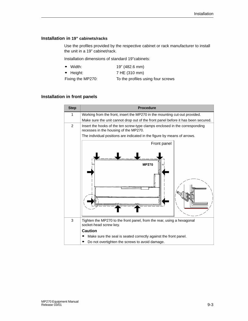
Installation
9-3MP270 Equipment ManualRelease 03/01
Installation in 19” cabinets/racks
Use the profiles provided by the respective cabinet or rack manufacturer to installthe unit in a 19” cabinet/rack.
Installation dimensions of standard 19”cabinets:
� Width:
� Height:
Fixing the MP270:
19” (482.6 mm)
7 HE (310 mm)
To the profiles using four screws
Installation in front panels
Step Procedure
1 Working from the front, insert the MP270 in the mounting cut-out provided.
Make sure the unit cannot drop out of the front panel before it has been secured.
2 Insert the hooks of the ten screw-type clamps enclosed in the correspondingrecesses in the housing of the MP270.
The individual positions are indicated in the figure by means of arrows.
Front panel
3 Tighten the MP270 to the front panel, from the rear, using a hexagonalsocket-head screw key.
Caution� Make sure the seal is seated correctly against the front panel.
� Do not overtighten the screws to avoid damage.

Installation
9-4MP270 Equipment Manual
Release 03/01
9.2 Electrical Installation
Electrical connections
The MP270 requires electrical connections
� to the power supply,
� to the configuration computer (PU or PC),
� to the PLC,
� to the printer.
An electrical connection to the PU/PC is only required for downloading the projectdata. Following the configuration and test phases, a serial printer can beconnected to the MP270 instead of the configuration computer.
EMC compatible installation
A precondition for error-free operation is an EMC compatible hardware design ofthe PLC and the use of interference-proof cables. The guidelines oninterference-free design of the PLCs apply equally to installation of the MP270.
!Caution
� Only shielded cables are permitted for all signal connections.
� Screw or lock all plug connections.
� Do not install signal lines in the same cable ducts as power cables.
� Siemens AG refuses to accept liability for malfunctions and damage arisingfrom use of self-made cables or cables from other manufacturers.
Grounding connection
Connect the grounding connection of the MP270 to the rack ground. To dothis, use the grounding screw supplied and a conductor cross-section of�2.5 mm2.

Installation
9-5MP270 Equipment ManualRelease 03/01
Connection elements
Figure 9-1 Arrangement of connection elements
No. Name Description/Use
Interfaces1): Level: Usage:� IF1 A RS232/TTY (active/passive) PLC
� IF2 RS232 PC, PU, printer
� IF1B2) RS422/RS485 (floating) PLC
Switch3) To configure interface IF1B
Power supply4) Connection for power supply (+24 V DC)
Backup battery Connection for optional backup battery
Grounding connection For connection to cabinet ground
Slot A For PC card or network card
Slot B For Compact Flash or network card

Installation
9-6MP270 Equipment Manual
Release 03/01
Communication options
Device Connection Interface
SIMATIC S5 � AS511 (TTY)
� PROFIBUS-DP
IF1 A
IF1 B
SIMATIC S7 � MPI
� PROFIBUS-DP
IF1 B
IF1 B
SIMATIC 505 � RS232
� RS422/RS485
IF1 A
IF1 B
Other PLCs � RS232/TTY
� RS422/RS485
IF1 A
IF1 B
Configuration computer � RS232 IF2
Printer
� Local printer
� Network printer
� RS232
� Network card
IF2
Slot A or Slot B
Reverse battery protection
Caution
The MP270 is equipped with reverse poling protection. This has no effect when aconnection already exists to another unit or a card is inserted in Slot A or Slot B.
Proceed as follows when commissioning:
1. Disconnect all connections to external units and remove any cards from Slot Aor Slot B.
2. Connect the MP270 to the power supply.
3. Switch on the power supply.If the MP270 does not start up, the connections are probably reversed. Swapthe connections over in this case.
4. When the MP270 has been powered up, connect the configuration computer orother periphery equipment to it.

Installation
9-7MP270 Equipment ManualRelease 03/01
Power supply
The power supply for the MP270 is connected at the 2-pin plug connector on theunderside of the unit. Use the 2-pin terminal block supplied for this purpose. Theterminal block is designed for cables with a cross-section not larger than 2.5 mm2.
The figure illustrates the pin assignment of the terminal block.
GND
+ 24 V DC
Please refer to the technical data in Appendix A for information on the powersupply requirements.
!Caution
� When using a 24 V supply, make sure that the extra-low voltage is isolatedsafely. Use only power supply units complying with IEC 364-4-41 orHD 384.04.41 (VDE 0100, Part 410)!
� The supply voltage must be within the specified voltage range. Voltagesoutside this range can cause malfunctions.

Installation
9-8MP270 Equipment Manual
Release 03/01
9.2.1 Connect configuration computer
Connection configuration
Figure 9-2 illustrates how to connect a configuration computer (PU or PC) to theMP270 for downloading project data. Standard cables are available for theconnections shown (refer to the ST80 catalog).
COMIF2
PC/PU 7xx
MP270
RS232 1)
IF1 BMPI/PROFIBUS-DP
1) Operating system update only via RS232 (refer to Chapter 13)
RS485
PC/PU 7xx
Figure 9-2 Connection configuration diagram for configuration computer

Installation
9-9MP270 Equipment ManualRelease 03/01
9.2.2 Connect PLC
Connection configuration
Figure 9-3 illustrates the basic connection possibilities between the MP270 andPLC. Standard cables are available for the connections shown (refer to the ST80catalog).
TTY activePU interface
SI 2
RS232(9/25-pin)
RS422(9-pin)
SIMATIC S5
TTY active
RS232
PLCs of othermanufacturers
RS422
RS422/RS485
CPU
SIMATIC 505
SIMATIC S71)
RS232/TTY
1) Use only the approved cables for connection to the SIMATIC S7.2) To enable operation using the serial interface, connect either the IF1A (RS232/TTY) or IF1B
(RS422/485), but not both. The 1F1B interface can be configured by means of the switch(Page 9-10).
3) Any PROFIBUS-DP bus terminal
IF1A2)
IF1B2)
RS485
RS485
MP270
PROFIBUS-DP
3)
Figure 9-3 Connection configuration for PLCs

Installation
9-10MP270 Equipment Manual
Release 03/01
Configure interface IF1B
The IF1B interface can be configured via the switches on the rear side of the unit.In this case, the RTS signal is interchanged for RS485 and the RS422 receivedata. By default, the RTS signal is not required by the communication peer.
The table shows the permissible switch settings.
Communication Switch Setting
PLCMPI/PPI
Standard cableMP270
ON
1234
No RTS on connector1)
PLCRS422/RS485
MP270ON
1234
PROFIBUS-DP/MPIMP270 ON
1234
RTS on pin 4 (default)
RTS on pin 9
(same as PU)
ON
1234
PLC
No RTS on connector1)
ON
1234
1) State on delivery
Compressing the internal program memory with SIMATIC S5
!Warning
With the SIMATIC S5, compression of the internal program memory on the PLC(PU “Compress” function, integrated FB COMPR) is not permitted when anoperating unit is connected. Compression modifies the absolute addresses of theblocks in the program memory. Since the operating unit only reads the address listduring startup, it does not detect any address modifications and subsequentlyaccesses the wrong memory areas.
If compression is inevitable during running operations, the operating unit must beswitched off before compressing.

Installation
9-11MP270 Equipment ManualRelease 03/01
9.2.3 Connect printer
Connection configuration
Figure 9-4 illustrates how to connect a printer to the MP270. The MP270 supportsthe following printer standards:
� compatible with ESC/P, 9-pin ESC/P or ESC/P2 (EPSON) e.g. EPSON FX850
� compatible with PCL3 (Hewlett Packard) e.g. HP LaserJet 5M
IF2
Local printer (serial)
ESC/P, 9-pin ESC/P, ESC/P2, PCL
RS232
MP270
Network printerSlot ASlot B
Network card
Figure 9-4 Printer connection configuration
Information on printer settings is provided on Page 8-8.
Notice� Only use a cable with braided metal screening grounded at each end for
connecting the MP270 and printer.
� Deactivate the (Page 3-8) Serial Transfer Remote Control option in theConfiguration menu if a serial printer is connected to the MP270 via the IF2interface.
� Some printers may require that the ASCII character set used in theconfiguration is defined on the printer as well.

Installation
9-12MP270 Equipment Manual
Release 03/01

10-1MP270 Equipment ManualRelease 03/01
Unit Description
In this chapter
This chapter provides information on:
� Dimensions (Page 10-2),
� Labeling the function keys (Page 10-3).
10

Unit Description
10-2MP270 Equipment Manual
Release 03/01
10.1 Dimensions
Mounting cut-out
For installation in the front panel, the MP270 requires a mounting cut-out (WxH) of436 +1 mm x 295 +1 mm. The thickness of the front panel must not exceed 6 mm.
Unit dimensions
���������������
�������
Hole details:
6.8
10.3
482.6
465.9
310.
3
235
5.850
431.6
289.
3
Figure 10-1 MP270 dimensions

Unit Description
10-3MP270 Equipment ManualRelease 03/01
10.2 Labeling Function Keys
LabelingThe MP270 function keys are labeled as follows on supply:
� F1 to F20 and
� K1 to K16.
The function keys are labeled by means of 10 labeling strips which are inserted inthe unit from the rear. These strips can be exchanged in order to label the MP270specifically for the system.
Exchange labeling strips
!Caution
Make sure that the MP270 is disconnected from the power supply.
Proceed as follows:
Step Procedure
1 Place the unit down with the front plate at the bottom.
2 Remove the labeling strips already inserted.
3 Insert the newly labeled strips in the slots in the front plate with the inscriptionfacing down. The individual positions are indicated in the figure by means ofarrows.
CautionBefore inserting the strips, wait until the inscription is dry. A keyboard foil which isdirty on the inside cannot be cleaned and can only be replaced at themanufacturer’s factory.

Unit Description
10-4MP270 Equipment Manual
Release 03/01
Create labeling strips
Only use transparent foil to create your own labeling strips so that the LEDs in thefunction keys remain visible. Label the foil either with a printer or a waterprooffelt-tip pen. Cut the strips according to the specifications depicted in Figure 10-2 .
18.5 18.5
32.5
55.7
9.3
79
102.
2
125.
5
31.5
53.7
9.3
86
242
(2x)
(8x)
LED window, transparent
Figure 10-2 Labeling strip dimensions
File
The ProTool CS configuration software contains formatted patterns for labelingfunction keys individually for various SIMATIC operating units.
The patterns for the MP270 are stored on the ProTool installation CD under\UTILITY\SLIDE270.DOC in Word format. This enables labeling strips to becreated for the MP270 for specific systems without extensive design and printingoperations.

11-1MP270 Equipment ManualRelease 03/01
Options
In this chapter
This chapter provides information on the options available with which to retrofit theMP270. The following options are available:
� Backup battery (Page 11-2)
� Memory card/Network card (Page 11-3)
11

Options
11-2MP270 Equipment Manual
Release 03/01
11.1 Backup Battery
Backup battery function
The battery ensures that the internal hardware clock of the MP270 continues to runeven when the power supply is interrupted. The clock is only backed up for a fewhours if no battery is available.
Installation
Step Procedure
1 Secure the new battery by means of two cable ties on the rear sideof the MP270. The relevant position is indicated in the diagrambelow by an arrow.
2 Insert the battery lead connection plug in the two-pole pin array. Theconnector is coded and thus protected against polarity reversal.
Further information
Information concerning replacing the battery, supply source and related safetynotes on handling and disposing of the batteries is provided on Page 12-2.

Options
11-3MP270 Equipment ManualRelease 03/01
11.2 Memory Card/Network Card
PurposeTwo slots are provided, namely Slot A and Slot B (Figure 11-1) located on the rearside of the unit in which to insert changeable storage media or network cards.
The interchangeable memory cards can be used, for example, to archive importantprocess data or execute a backup/restore of the internal Flash memory (refer toPage 3-15). Information on using the network card is provided in Chapter 8.5.
Slot A
(1)
(2)
Slot B
Figure 11-1 Position of the slots
Cards supported
The MP270 supports the use of all standard cards which operate with aprogramming voltage of 5 V (types I and II), e.g.:
� Slot A (PC card): – ATA Flash card
– NE2000 compatible network card (SIMATIC NET CP1511)
� Slot B (Compact Flash card): – ATA Flash card
– NE2000 compatible network card

Options
11-4MP270 Equipment Manual
Release 03/01
InstallationProceed as follows to install a card:
Step Procedure
1 Remove bracket (1) or (2), depending on the slot concerned.
2 Insert the card in Slot A or Slot B according to the card type.
3 Reinstall the bracket, (1) or (2), to secure the card.
Caution
Stop the runtime software before inserting the card. Operate the operatingelement linked to the Exit_runtime function in the configuration.
Please observe the related safety notes provided on Page 9-6.
Remove the card
Caution
Before removing a card, ensure that the MP270 does not access the card duringthe removal process.
Before removing the card, either use the operating element linked with theClose_archive function in the configuration or stop the runtime software. Operatethe operating element linked to the Exit_runtime function in the configuration. Waituntil the MP270 Start menu (Figure 3-1, Page 3-7) is displayed. This may takeseveral minutes, depending on the size and number of archives stored.
Switch MP270 off with card inserted
Caution
Always terminate the runtime software before switching off the voltage supply inorder to prevent loss of data.
To terminate the runtime software, press the operating element assigned theExit_runtime function in the configuration. Wait until the MP270 start menu(Figure 3-1, Page 3-7) appears and then switch off the power supply. Changeoverto the Start menu may take several minutes depending on the size and number ofarchives stored.
If the voltage supply is inadvertently interrupted during operation, the MP270checks the memory card when the power supply is returned and displays a dialogwindow asking whether defect sectors should be repaired.

12-1MP270 Equipment ManualRelease 03/01
Maintenance/Upkeep
Scope
The MP270 has been designed for low maintenance operation. Maintenance of theunit is limited to
� regular cleaning of the keyboard foil and screen,
� changing the optional backup battery.
12.1 Clean Screen and Keyboard Foil
Preparation
Clean the MP270 screen and the keyboard foil at regular intervals. Use a dampcloth.
!Caution
Do not clean the unit while it is turned on. This ensures that functions are notinadvertently triggered on touching the keys.
Cleaning agents
Only use water and washing up liquid or screen cleaning foam to dampen cloths.Never spray the cleaning agent directly onto the screen, but onto the cleaningcloth. Never use aggressive solvents or scouring powder.
12
Maintenance/Upkeep
12-2MP270 Equipment Manual
Release 03/01
12.2 Replacing the Optional Backup Battery
Backup battery function
An optional backup battery is available for the MP270 (refer to Chapter 11). Thebattery ensures that the internal hardware clock continues to run even when thepower supply is interrupted.
Under normal operating conditions, the battery has a service life of approx. 4years. It is not part of the material supplied with the MP270.
Supply source
The battery can be ordered from the Siemens spare parts service. It is shippedready for installation with a lead and connector. Please refer to our catalog ST80for the order number.
Before replacing
Observe the following before changing the battery:
!Caution
� Change the battery while power is still being supplied to ensure the internalhardware clock continues to run.
� The battery must be changed by a properly qualified person.
� Before replacing the battery, refer to the ESD Guidelines in Appendix D.

Maintenance/Upkeep
12-3MP270 Equipment ManualRelease 03/01
Procedure
Step Procedure
1 Remove the battery lead connector from the two-pin plug connectoron the unit.
2 The battery is normally secured by means of two cable ties on therear side of the MP270. Cut the cable ties, using pliers for instance,and remove the empty battery.
3 Secure the new battery by means of two cable ties on the rear sideof the MP270.
4 Insert the battery lead connector back into the socket. Theconnector is coded and thus protected against polarity reversal.
General notes
Please observe the following safety notes to ensure correct handling and disposalof lithium batteries:
!Warning
� If the lithium battery is not handled properly, there is a risk of explosion.
� Batteries
– should never be charged
– should not be opened
– should not be short-circuited
– should be safeguarded against polarity reversal
– should not be exposed to temperatures in excess of 100 �C
– should be protected against direct sunlight.
� Do not allow condensation to form on batteries.
� Should shipping become necessary, ensure compliance with the DangerousChemicals Ordinance for the carrier concerned (coding obligation).
� Treat used lithium batteries as special waste. Pack them in separate leakproofplastic bags to dispose of them.

Maintenance/Upkeep
12-4MP270 Equipment Manual
Release 03/01

13-1MP270 Equipment ManualRelease 03/01
Operating System Update
Purpose
If there is a conflict between the configuration software version and currentoperating system on the MP270, downloading of a configuration from theconfiguration computer to the MP270 is terminated and a compatibility conflict isindicated.
In this case, synchronize the MP270 operating system with the version of theSIMATIC ProTool CS configuration software. The procedure is described below.
Note
Updating the operating system causes all the existing data on the MP270 to bedeleted!
Tip:Before updating the operating system, export the user data (passwords andrecipes) on the internal Flash memory to an external data medium. Import the dataagain after updating the operating system.
Procedure
Proceed as follows in order to adapt the operating system on the MP270 to theconfiguration software version used:
Step Procedure
1 Switch off the power supply for the MP270.
2 Connect the IF2 (RS232) interface on the MP270 to a serial interface on theconfiguration computer via a commercially available serial zero modem cable.
3 Start the PTUpdate utility program on the configuration computer. It is containedon the configuration software installation CD. It is located in the directory\Images.
4 Select menu item File → Open and open the image file (file extension .img)appropriate for the MP270. The image file are located in the same directory asthe PTUpdate utility program. The file name contains the character string MP270.When the image file has been opened successfully, various information relatedto the version status appears on the screen.
13

Operating System Update
13-2MP270 Equipment Manual
Release 03/01
ProcedureStep
5 Select the menu item File → Settings. Set the interface and applicable baud rate(max. 115200) on the designated interface for the download.
6 Start downloading with the menu option File → Download. When the appropriatemessage appears on the screen, switch on the power supply for the MP270.
If downloading is unsuccessful, repeat the above procedure.
When downloading is successful, the MP270 contains no project data. Thebehavior of the MP270 when no configuration has been loaded is described inChapter 3.1.

APPENDICES
A Technical Data
B Interface Assignments
C System Messages
D ESD Guidelines
E SIMATIC HMI Documentation

APPENDICES
M-2MP270 Equipment Manual
Release 03/01

A-1MP270 Equipment ManualRelease 03/01
Technical Data
In this Appendix
This Appendix contains the following technical data for the MP270:
� Housing
� Processor
� Memory
� Software
� Display
� Keyboard
� Power supply
� Backup battery (option)
� Network card (option)
� Ambient conditions
� Noise immunity / Noise transmission
� Approvals
A

Technical Data
A-2MP270 Equipment Manual
Release 03/01
Housing
External dimensions (W x H) 482.6 mm x 310.3 mm
Mounting cut-out (W x H) 436+1 mm x 295+1 mm
Mounting depth 50 mm
Degree of protection� Front panel
� Rear panel
IP65/NEMA 4
IP20
Weight Approx. 5 kg
Processor
Type 32 bit CPU
Memory
Configuration memory To 4 Mbyte
Storage media
� Expansion slot for PC card e.g. ATA Flash card
� Slot for Compact Flash card e.g. ATA Flash card
Software
Operating system environment MS Windows CE
Color display
LCD type STN LCD TFT LCD
Active screen diagonal 10.4”
Resolution (pixels) 640 x 480 (VGA)
No. of colors 256
Back-lighting CCFL tubeHalf Brightness Life 1) Approx. 50,000 h Approx. 40,000 h
1) Time period after which the brightness of the lighting tube only achieves 50 % of itsoriginal value. The specified value is dependent on the operating temperature.

Technical Data
A-3MP270 Equipment ManualRelease 03/01
Keyboard
Type Membrane keyboard
System keys with dedicated functions 33 (3 with LEDs)
Configurable function keys
� Number 36 (28 with LEDs)
� Those usable as softkeys 20
� Labeling System-specific with labeling strips
Power supply
Rated voltage + 24 V DC
Permissible voltage range +18.0...+30.0 V DC
Max. permissible transients 35 V (500 msec)
Time between two transients 50 sec minimum
Power consumptionTypical
Max. constant current
Approx. 0.6 A
Approx. 0.9 A
Switch-on current I2t Approx. 0.5 A2s
Fuse, internal Electronic
Backup battery (option)
Type Lithium battery
Voltage/Capacity 2) 3.6 V/approx. 1.5 Ah
Service life Approx. 4 years
2) Technical details subject to change without notice.
Network card (option)
Type NE2000-compatible, e.g. SIMATIC NET CP15113)
3) From Edition 4

Technical Data
A-4MP270 Equipment Manual
Release 03/01
Ambient conditions
Location
Max. permissible angle of inclinationwithout external ventilation
Vertical
�35�
Max. permissible ambient temperature
� Operation
STN display TFT display
– Vertical installation
– Installation angled from theperpendicular to max. 35�
0...+45 ��
0...+35 ��
0...+50 ��
0...+35 ��
� Shipping, storage –20...+60���
Relative humidityOperation
Shipping, storage
20...85%, no condensation
5...85%, no condensation
Shock resistanceOperation
Shipping, storage
15 g/11 msec
25 g/6 msec
VibrationOperation 0.035 mm (10 – 58 Hz)
1 g (58 – 500 Hz)
Shipping, storage 3.5 mm (5 – 8.5 Hz)1 g (8.5 – 500 Hz)
Max. pressure difference (front/rear side) 2 hPa
Barometric pressure
Operation
Shipping, storage
706 to 1030 hPa
581 to 1030 hPa

Technical Data
A-5MP270 Equipment ManualRelease 03/01
Compliance of the named products with the regulations of Directive 89/336 EEC isverified by conformance with the following standards:
Noise immunity
Static discharge (contact discharge/air discharge)
EN 61000-4-2
6 kV/8 kV
RF irradiation EN 61000-4-3
10 V/m, 80% AM,
1 kHz
Pulse modulation ENV 50204
900 MHz �5 MHz
10 V/meff., 50% ED, 200 Hz
RF conduction EN 61000-4-6
150 kHz – 80 MHz
10 V, 80% AM, 1 kHz
Burst interference
Mains lines
Supply lines
Process data lines
Signal lines
EN 61000-4-4
2 kV
2 kV
2 kV
1 kV
Radio interference
Radio interference level complying to EN 55011
Class A

Technical Data
A-6MP270 Equipment Manual
Release 03/01
The following approvals have been applied for or already granted on supply.Please refer to the rating plate on the rear of the unit for identification.
Approvals
UL approval UL Recognition Mark 4)
Underwriters Laboratories (UL) complying with Standard UL 508, File E 120869
cUL approval In accordance with the UL/CSA Approval Agreement
FM Approval FM Approval
Complying with Factory Mutual Approval Standard Class Number3611 Hazardous (classified) Locations Class I,
Division 2,Group A,B,C, D
Warning:
Personal injury and equipment damage can occur.
Personal injury and equipment damage can occur inhazardous areas if a plug connection is disconnectedfrom the operating unit while the system is running.
In hazardous areas, always switch off the power supplyto the operating unit before disconnecting plugs.
!
Warning:
DO NOT DISCONNECT WHILE CIRCUIT IS LIVEUNLESS LOCATION IS KNOWN TO BE NON-HAZARDOUS.
!
4) The UL and CSA file numbers are dependent on the production site. The numbersspecified here changes according to the change of production site.

B-1MP270 Equipment ManualRelease 03/01
Interface Assignment
IF1ATable B-1 15-pin Sub-D socket
Pin RS232 TTY General
1 Screening
2 – RxD– RxD–
3 RxD – –
4 TxD – –
5 CTS – –
6 – TxD+ –
7 – TxD– RTS
8 Screening
9 – RxD+ –
10 RTS – –
11 – +20 mA –
12 GND
13 – +20 mA –
14 +5 V/100 mA
15 GND
IF1BTable B-2 9-pin Sub-D socket (configuration via switch, see Page 9-10)
Pin RS422 RS485 / PROFIBUS-DP / MPI
1 N. c.
2 N. c.
3 TxD+ Data B
4 RxD+ –
5 GND (floating) GND (floating)
6 +5 V (floating) +5 V (floating)
7 N. c.
8 TxD– Data A
9 RxD– –
B
8 1
15 9
5 1
9 6

Interface Assignment
B-2MP270 Equipment Manual
Release 03/01
IF2Table B-3 9-pin Sub–D plug (pin)
Pin RS232
1 DCD
2 RxD
3 TxD
4 DTR
5 GND
6 DSR
7 RTS
8 CTS
9 RI
5 1
9 6

C-1MP270 Equipment ManualRelease 03/01
System Messages
In this chapter
This chapter contains a selection of important system messages forWindows-based systems. The table indicates when the messages occur and howthey, or their cause, can be cleared. Not every message is relevant for eachoperating unit.
System message parameters
The system messages may contain parameters which are not decoded for the userbut which are relevant in respect of the cause of an error since they provide areference to the source code from ProTool/Pro Runtime. These parameters areissued according to the text “Error code:”
Notice
System messages are issued in the language currently set on the operating unit.
Number Effect/Cause Remedy
10000 The print job could not be started or wasterminated for an unknown reason.
The printer is incorrectly configured.Or: There are no rights for a network printeravailable.
Configure the printer again.
Initiate the assignment of rights for a networkprinter.
10001 No printer has been installed or no standardprinter configured.
Install a printer and/or mark one as standardprinter.
10002 The intermediate buffer for printing graphicsis full. Up to two graphics can be buffered.
Do not issue print jobs so quickly insuccession.
10003 Graphics can be buffered again. –
10004 The intermediate buffer for printing lines intext mode (e.g. messages) is full. Up to 1000lines can be buffered.
Do not issue print jobs so quickly insuccession.
10005 Lines of text can be buffered again. –
10006 The Windows print system reports an error.For information on the cause, refer to the textprinted and, if available, the error number.
Printing is not performed or it is incorrect.
Repeat the action, if necessary.
C

System Messages
C-2MP270 Equipment Manual
Release 03/01
RemedyEffect/CauseNumber
20010 A fault has occurred in the script line called infrom the specified script. Execution of thescript function was, therefore, terminated.
In this case, it is advisable to check anyprevious system messages too.
Select the specified script line in theconfiguration.
Check tags, whether the types used arepermissible.
Check Functions, whether the number andtypes of parameter are correct.
20011 An error has occurred in a script called in bythe script specified. Execution of the scriptfunction has, therefore, been terminated inthe subscript.
In this case, it is advisable to check anyprevious system messages too.
Select the scripts from the configurationwhich were directly or indirectly called in viathe specified script.
Check tags, whether the types used arepermissible.
Check Functions, whether the number andtypes of parameter are correct.
20012 Inconsistent configuration data is present.Therefore, the script could not be created.
Compile the configuration again.
20013 VBScript.dll is not correctly installed.Therefore, no scripts can be executed.
Re-install ProTool/Pro RT.
20014 A value is returned by the script functionwhich is not written in any configured returntag.
Select the specified script in theconfiguration.
Check whether the script name has beenassigned a value.
20015 Too many scripts have been triggered inquick succession.If more than 20 scripts are queued to beprocessed, any subsequent scripts arerejected.In this case, the script indicated in themessage is not executed.
Check where the scripts are being triggeredfrom.
Extend the times, e.g. the polling time of thetags, which trigger the scripts.
30010 The tag could not accept the function result,e.g. in the case of exceeding the valuerange.
Check the tag type of the function parameter.
30011 A function could not be executed becausethe function was assigned an invalid value ortype in the parameter.
Check the parameter value and tag type ofthe invalid parameter.
If a tag is used as a parameter, check itsvalue.
40010 The function could not be executed since theparameters could not be converted to acommon tag type.
Check the parameter types in theconfiguration.
40011 The function could not be executed since theparameters could not be converted to acommon tag type.
Check the parameter types in theconfiguration.
50000 The operating unit receives data faster than itis capable of processing. Therefore, nofurther data is received until the datacurrently available has been processed.Data exchange then resumes.
–
50001 Data exchange has been resumed. –

System Messages
C-3MP270 Equipment ManualRelease 03/01
RemedyEffect/CauseNumber
60000 This message is generated by the function“Display system messages”. The text to bedisplayed is transferred to the function as aparameter.
–
60010 The file could not be copied in the directiondefined because one of the two files iscurrently open or the source/target path isnot available.
It is possible that the Windows NT user hasno access rights to one of the two files.
Restart the function or check the paths of thesource/target files.
Using Windows NT with NTFS: The userexecuting ProTool/Pro RT must be grantedaccess rights for the files.
60011 An attempt was made to copy a file to itself.
It is possible that the Windows NT user hasno access rights to one of the two files.
Check the path of the source/target file.
Using Windows NT with NTFS: The userexecuting ProTool/Pro RT must be grantedaccess rights for the files.
70010 The application could not be started becauseit could not be found in the path specified orinsufficient memory space was available.
Check whether the application exists in thespecified path or close other applications.
70011 The system time could not be modified.Possible causes:
� an impermissible time was transferred inthe PLC job,
� the Windows NT user has no user rightsto modify the system time.
Check the time which is to be set.
Under Windows NT: The user executingProTool/Pro RT must be assigned the rightsto modify the system time from Windows NT(administration/user manager, guidelines).
70012 An error occurred when executing thefunction “Exit Runtime” with the option “Exitalso Windows”.
Windows and ProTool/Pro RT are notterminated.
A possible cause is that other applicationscannot be terminated.
Terminate all applications currently running.
Then terminate Windows.
70013 The system time could not be modifiedbecause an invalid value was entered.Incorrect separators may have been used.
Check the time which is to be set.
70014 The system time could not be modified.Possible causes:
� an impermissible time was transferred
� the Windows NT user has no user rightsto modify the system time,
� Windows rejects the setting request.
Check the time which is to be set.
Under Windows NT: The user executingProTool/Pro RT must be assigned the rightsto modify the system time from Windows NT(administration/user manager, guidelines).
70015 The system time could not be read becauseWindows rejects the reading function.
–
70016 An attempt was made to select a screen bymeans of a function or job. This is notpossible because the screen numberspecified does not exist.
Or: a screen could not be generated due toinsufficient system memory.
Check the screen number in the function orjob with the screen numbers configured.
Refer the number to a screen, if necessary.

System Messages
C-4MP270 Equipment Manual
Release 03/01
RemedyEffect/CauseNumber
70017 Date/Time is not read from the area pointerbecause the address set in the PLC is eithernot available or has not been set up.
Change the address or set up the address inthe PLC.
70018 Acknowledgement that the password list hasbeen successfully imported.
–
70019 Acknowledgement that the password list hasbeen successfully exported.
–
70020 Acknowledgement for activation of messagerecording.
–
70021 Acknowledgement for deactivation ofmessage recording.
–
70022 Acknowledgement to starting the ”ImportPassword List” action.
–
70023 Acknowledgement to starting the ”ExportPassword List” action.
–
80001 The archive specified is filled to the sizedefined (in percent) and must be storedelsewhere.
Store the file or table by executing a ‘move’or ‘copy’ function.
80002 A line is missing in the specified archive. –
80003 The copying process for archiving was notsuccessful.
In this case, it is advisable to check anysubsequent system messages, too.
–
80006 Since archiving is not possible, this causes apermanent loss of the functionality.
In the case of databases, check whether thecorresponding data source exists and startup the system again.
80009 A copying action has been completedsuccessfully.
–
80010 Since the path was incorrectly entered inProTool, this causes a permanent loss of thefunctionality.
Configure the path for the respective archiveagain and restart the system when the fullfunctionality is required.
80012 Archive values are stored in a buffer. If thevalues are read to the buffer faster than theycan be physically written (e.g. using a harddisk), overloading may occur and recordingis then stopped.
Archive less values.
Or increase the recording interval.
80013 The overload status no longer applies.Archiving resumes the recording of allvalues.
–
80014 The same action was triggered twice in quicksuccession. Since the process is already inoperation, the action is only carried out once.
–
80016 The archives are separated by the functionClose archive and the incoming entriesexceed the defined buffer size.
All the jobs in the buffer are deleted.
Reconnect the archives.

System Messages
C-5MP270 Equipment ManualRelease 03/01
RemedyEffect/CauseNumber
80017 The incoming entries cause the definedbuffer size to be exceeded. This can becaused, e.g. by several copying actionsbeing activated at the same time.
All the copy jobs in the buffer are deleted.
Terminate the copy process.
80018 All the archives are reconnected by means ofthe DB layer, e.g. after executing the functionOpen_archive.
Values are then written back into the tables.
–
80019 All the archives are separated from the DBlayer and all connections terminated, e.g.after executing the function Close_archive.
Values are temporarily buffered and written inthe tables when the connection isre-established.
There is no connection to the storagemedium and a change can take place.
–
80020 The max. number of simultaneouslyactivated copy actions has been exceeded.
Copying is not executed.
Wait until the current copying actions havebeen completed and restart the last copyaction.
80021 An attempt was made to delete an archivewhich is still involved with a copy action.
Deletion has not been executed.
Wait until the current copying action hasbeen completed and restart the last action.
80022 An attempt was made to start a sequencearchive, which is not a sequence archive,from an archive using the functionStart_sequence_archive.
No sequence archive is created.
Check the project for the following:
� the function Start_sequence_archive iscorrectly configured.
� the variable parameters are beingcorrectly provided at the operating unit.
80023 An attempt was made to copy an archive toitself.
The archive is not copied.
Check the project for the following:
� the function Copy_archive is correctlyconfigured.
� the variable parameters are beingcorrectly provided at the operating unit.
80024 The function Copy_archive is configured notto permit copying when the target archivealready contains data (Parameter: Writemode).
The archive is not copied.
Modify the function Copy_archive in theproject, if necessary.
Before initiating the function, delete the targetarchive.
80025 The copy action is interrupted.
Data written up to this point is retained.Deletion of the target table (if configured) isnot executed.
The cancellation is documented by an errorentry $RT_ERR$ at the end of the targettable.
–

System Messages
C-6MP270 Equipment Manual
Release 03/01
RemedyEffect/CauseNumber
80026 The message is issued after all the archiveshave been successfully initialized. Values arewritten in the archives from this moment on.Prior to this, no values are archived eventhough the runtime software is operating.
–
80027 The internal Flash memory has beenspecified as the memory location for anarchive. This is not permissible.
No values will be archived for this archiveand the archive will not be created.
Configure ”Storage Card” as the memorylocation or a network path.
80028 The message serves as a statusacknowledgment that initialization of thearchives is currently running. No values arearchived until system message 80026 isissued.
–
80029 The number of archives specified in themessage could not be initialized. Initializationof the archives has been completed.
The faulty archives are not available forarchiving jobs.
Evaluate the additional system message,related to this message, which is also issued.
Check the configuration, the ODBC (OpenDatabase Connectivity) and the specifieddrive.
110000 The operating mode status has beenchanged. The operating mode is now offline.
–
110001 The operating mode status has beenchanged. The operating mode is now online.
–
110002 The operating mode status has not beenchanged.
Check the connection to the PLCs.
Check whether the address area for the areapointer “Coordination” in the PLC isavailable.
110003 The operating status of the PLC specified ischanged by the function Connect/DisconnectPLC.
The operating mode is now offline.
–
110004 The operating status of the PLC specified ischanged by the function Connect/DisconnectPLC.
The operating mode is now online.
–
110005 An attempt was made to use the functionConnect/Disconnect PLC to switch thespecified PLC to operating mode onlinealthough the entire system is in operatingmode Offline. This switch-over is notpermissible.
The PLC remains in operating mode offline.
Switch the complete system to operatingmode online and execute the function again.
120000 The trend is not displayed because anincorrect axis to the trend, or incorrect trend,has been configured.
Change the configuration.
120001 The trend is not displayed because anincorrect axis to the trend, or incorrect trend,has been configured.
Change the configuration.

System Messages
C-7MP270 Equipment ManualRelease 03/01
RemedyEffect/CauseNumber
120002 The trend is not displayed because the tagassigned tries to access an invalid PLCaddress.
Check whether the data area for the tagexists in the PLC, the configured address iscorrect or the value range for the tag iscorrect.
130000 The action was not executed. Close other applications.
Delete files no longer required from the harddisk.
130001 The action was not executed. Delete files no longer required from the harddisk.
130002 The action was not executed. Close other applications.
Delete files no longer required from the harddisk.
130003 No target data carrier is inserted. Theprocess is stopped.
Check, for example, whether:
� access has been made to the correctdata carrier
� the data carrier has been inserted
130004 The target data carrier is write-protected. Theprocess is stopped.
Check whether access has been made tothe correct data carrier. Remove the writeprotection.
130005 The file is write-protected. The process isstopped.
Check whether access has been made tothe correct file. Modify the file attributes, ifnecessary.
130006 No access to file is possible. The process isstopped.
Check, for example, whether:
� access has been made to the correct file
� the file exists
� a different action prevents simultaneousaccess to the file
140000 Online connection to the PLC has beensuccessfully established.
–
140001 Online connection to the PLC has beendisconnected.
–
140003 No tag updating or writing is executed. Check the connection and whether the PLCis switched on.
Check the parameter definitions in theControl Panel using “Set PU/PC interface”.
Restart the system.
140004 No tag updating or writing is executedbecause the access point or the subrackconfiguration is incorrect.
Check the connection and whether the PLCis switched on.
Check the access point or the subrackconfiguration (MPI, PPI, PROFIBUS) in theControl Panel with “Set PU/PC interface”.
Restart the system.

System Messages
C-8MP270 Equipment Manual
Release 03/01
RemedyEffect/CauseNumber
140005 No tag updating or writing is executedbecause the address of the operating unit isincorrect (possibly too high).
Use a different operating unit address.
Check the connection and whether the PLCis switched on.
Check the parameter definitions in theControl Panel using “Set PU/PC interface”.
Restart the system.
140006 No tag updating or writing is executedbecause the baud rate is incorrect.
Select a different baud rate in ProTool/Pro(according to subrack, profile,communication peer, etc.).
140007 No tag updating or writing is executedbecause the bus profile is incorrect(see %1).
The following parameters could not beentered in the registry:
1: Tslot2: Tqui3: Tset4: MinTsdr5: MaxTsdr6: Trdy7: Tid18: Tid29: Gap Factor10: Retry Limit
Check the user defined bus profile.
Check the connection and whether the PLCis switched on.
Check the parameter definitions in theControl Panel using “Set PU/PC interface”.
Restart the system.
140008 No tag updating or writing is executedbecause the configuration data is incorrect:
The following parameters could not beentered in the registry:
0: General errors1: Incorrect version2: Profile cannot be entered in the registry.3: Sub-network type cannot be entered in
the registry.4: Target rotation time cannot be entered
in the registry.5: Highest address (HSA) incorrect.
Check the connection and whether the PLCis switched on.
Check the parameter definitions in theControl Panel using “Set PU/PC interface”.
Restart the system.
140009 No tag updating or writing is executedbecause the module for the S7communication was not found.
Re-install the module in the Control Panelusing “Set PU/PC interface”.
140010 No S7 communication peer could be foundbecause the PLC is switched off.
DP/T:The option “Is not active as the only master”is set in the Control Panel under “Set PU/PCinterface”.
Switch the PLC on.
DP/T:If only one master is connected to thenetwork, deactivate the option “Is not activeas the only master” in “Set PU/PC interface”.
If the network has more than one master,switch this master on. Do not modify anysettings here, otherwise a bus fault mayoccur.
140011 No tag updating or writing is executedbecause communication is interrupted.
Check the connection and that thecommunication peer is switched on.

System Messages
C-9MP270 Equipment ManualRelease 03/01
RemedyEffect/CauseNumber
140012 There is an initialization problem (e.g. whenProTool/Pro RT has been terminated in theTask Manager).
Or: another application (e.g. STEP7, WINCC)is active with different bus parameters andthe driver cannot be started with the new busparameters (e.g. baud rate).
Restart the operating unit.
Or start ProTool/Pro RT first and then theother applications.
140013 The MPI cable is not plugged in and, thus,there is no power supply.
Check the connections.
140014 – Modify the operating unit address in theconfiguration in PLC.
140015 Incorrect baud rate
Or: incorrect bus parameter (e.g. HSA)
Or: OP address HSA
Or: incorrect interrupt vector (interrupt doesnot arrive at the driver)
Correct the incorrect parameters.
140016 – Change the interrupt number.
140017 – Change the interrupt number.
150000 No more data is read or written.
Possible causes:
� The cable is defective.
� The PLC does not respond, is defective,etc.
� Connection is established via the wronginterface.
� The system is overloaded.
Check that the cable is plugged in, the PLCis operational, the correct interface is used.
Reboot the system if the system message isdisplayed continuously.
150001 Connection is re-established because thecause of the interruption has beeneliminated.
–
160000 No more data is read or written.
Possible causes:
� The cable is defective.
� The PLC does not respond, is defective,etc.
� Connection is established via the wronginterface.
� The system is overloaded.
Check that the cable is plugged in, the PLCis operational, the correct interface is used.
Reboot the system if the system message isdisplayed continuously.
160001 Connection is re-established because thecause of the interruption has beeneliminated.
–
160010 There is no connection to the serverbecause the server identification (CLS-ID)cannot be established.
Values cannot be read or written.
Check the access rights.

System Messages
C-10MP270 Equipment Manual
Release 03/01
RemedyEffect/CauseNumber
160011 There is no connection to the serverbecause the server identification (CLS-ID)cannot be established.
Values cannot be read or written.
Check, for example, whether:
� the server name is correct
� the computer name is correct
� the server is registered
160012 There is no connection to the serverbecause the server identification (CLS-ID)cannot be established.
Values cannot be read or written.
Check, for example, whether:
� the server name is correct
� the computer name is correct
� the server is registered
Information for experienced users:Interpret the value from HRESULT.
160013 The specified server was started as InProcServer. This has not been released and maypossibly lead to incorrect behavior becausethe server is running in the same processarea as the ProTool/Pro RT runtime software.
Configure the server as OutProc Server orLocal Server.
1700001) S7 diagnostics messages are not displayedbecause it is not possible to logon to the S7diagnostics with this unit. The serviceprogram is not supported.
–
1700011) The S7 diagnostics buffer cannot bedisplayed because communication with thePLC has been switched off.
Switch the PLC online
1700021) The S7 diagnostics buffer cannot bedisplayed because reading in the diagnosticsbuffer (SZL) was terminated due to an error.
–
170003 1) The display of an S7 diagnostics message isnot possible. An internal error %2 has beenreported.
–
170004 1) The display of an S7 diagnostics message isnot possible. An internal error with error class%2, error number %3 has been reported.
–
170007 1) It is not possible to read in the S7 diagnosticsbuffer (SZL) because it was terminated withan internal error with error class %2 and errorcode %3.
–
180000 A component/OCX receives configurationdata with a version identification which is notsupported.
Install a newer component.
180001 The system is overloaded because too manyactions have been activated simultaneously.
Not all the actions can be executed, someare rejected.
� Increase the configured cycle times orbasic clock.
� Generate the messages slower (polling).
� Trigger the scripts and functions atgreater intervals.
� If the message appears more frequently: Restart the operating unit.
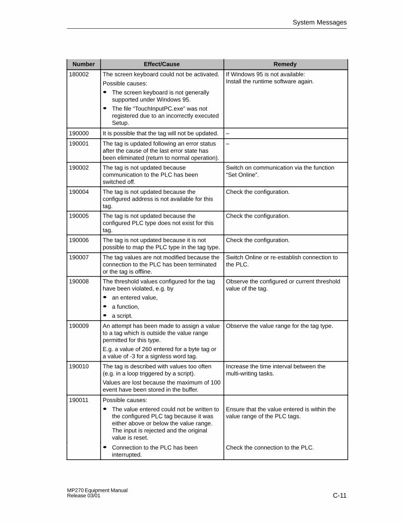
System Messages
C-11MP270 Equipment ManualRelease 03/01
RemedyEffect/CauseNumber
180002 The screen keyboard could not be activated.
Possible causes:
� The screen keyboard is not generallysupported under Windows 95.
� The file “TouchInputPC.exe” was notregistered due to an incorrectly executedSetup.
If Windows 95 is not available: Install the runtime software again.
190000 It is possible that the tag will not be updated. –
190001 The tag is updated following an error statusafter the cause of the last error state hasbeen eliminated (return to normal operation).
–
190002 The tag is not updated becausecommunication to the PLC has beenswitched off.
Switch on communication via the function“Set Online”.
190004 The tag is not updated because theconfigured address is not available for thistag.
Check the configuration.
190005 The tag is not updated because theconfigured PLC type does not exist for thistag.
Check the configuration.
190006 The tag is not updated because it is notpossible to map the PLC type in the tag type.
Check the configuration.
190007 The tag values are not modified because theconnection to the PLC has been terminatedor the tag is offline.
Switch Online or re-establish connection tothe PLC.
190008 The threshold values configured for the taghave been violated, e.g. by
� an entered value,
� a function,
� a script.
Observe the configured or current thresholdvalue of the tag.
190009 An attempt has been made to assign a valueto a tag which is outside the value rangepermitted for this type.
E.g. a value of 260 entered for a byte tag ora value of -3 for a signless word tag.
Observe the value range for the tag type.
190010 The tag is described with values too often(e.g. in a loop triggered by a script).
Values are lost because the maximum of 100event have been stored in the buffer.
Increase the time interval between themulti-writing tasks.
190011 Possible causes:
� The value entered could not be written tothe configured PLC tag because it waseither above or below the value range.The input is rejected and the originalvalue is reset.
Ensure that the value entered is within thevalue range of the PLC tags.
� Connection to the PLC has beeninterrupted.
Check the connection to the PLC.

System Messages
C-12MP270 Equipment Manual
Release 03/01
RemedyEffect/CauseNumber
190012 It is not possible to convert a value from asource format to a target format, e.g.:
� A value should be assigned to a counterwhich is outside the valid,PLC-dependent value range.
� A tag of the type Integer should beassigned a value of the type String.
Check the value range or type of thevariable.
190100 The area pointer is not updated because theconfigured address for this area pointer is notavailable.
Type:1 Event messages2 Alarm messages3 PLC acknowledgment4 Operating unit acknowledgment5 LED assignment6 Trend request7 Trend transfer 18 Trend transfer 2
No.:is the consecutive number displayed inProTool/Pro.
Check the configuration.
190101 The area pointer is not updated because it isnot possible to map the PLC type in the areapointer type.
Parameter type and no.:See message 190100
–
190102 The area pointer is updated following anerror status after the cause of the last errorstate has been eliminated (return to normaloperation).
Parameter type and no.:See message 190100
–
200000 Coordination is not executed because theaddress configured in the PLC does notexist/has not been set up.
Change the address or set up the address inthe PLC.
200001 Coordination is not executed because theaddress configured in the PLC cannot bewritten.
Change the address or set up the address inthe PLC in an area which can be written.
200002 Coordination is not carried out at the momentbecause the address format of the areapointer does not match the internal storageformat.
Internal error
200003 Coordination can be executed againbecause the last error status has beeneliminated (return to normal operation).
–
200004 It is possible that coordination is notexecuted.
–

System Messages
C-13MP270 Equipment ManualRelease 03/01
RemedyEffect/CauseNumber
200005 No more data is read or written.
Possible causes:
� The cable is defective.
� The PLC does not respond, is defective,etc.
� The system is overloaded.
Check that the cable is connected and thePLC is in order.
Reboot the system if the system message isdisplayed continuously.
210000 Jobs are not processed because theaddress configured in the PLC does notexist/has not been set up.
Change the address or set up the address inthe PLC.
210001 Jobs are not processed because theaddress configured in the PLC cannot bewritten to/read from.
Change the address or set up the address inthe PLC in an area which can be writtento/read from.
210002 Commands are not executed because theaddress format of the area pointer does notmatch the internal storage format.
Internal error
210003 The job mailbox is processed again becausethe last error status has been eliminated(return to normal operation).
–
210004 It is possible that the job mailbox is notprocessed.
–
210005 A PLC job was triggered by an impermissiblenumber.
Check the PLC program.
210006 A fault occurred while attempting to executethe PLC job. The PLC job is, therefore, notexecuted.
Observe the subsequent/previous systemmessage, if appropriate.
Check the parameter types in the PLC job.
Compile the configuration again.
220000 2) See footnote See footnote
220001 The tag is not downloaded because theassociated channel/the unit does not supportdownloading the data type bool/bit.
Change the configuration.
220002 The tag is not downloaded because theassociated channel/the unit does not supportdownloading the data type byte.
Change the configuration.
220003 The associated driver could not be uploaded.It is possible that the driver is not installed.
Install the driver by re-installingProTool/Pro RT.
220004 Communication is terminated and no updateis executed because the cable is notconnected or is defect etc.
Check the connection.
220005 Communication is running. –
220006 The connection is established to thespecified PLC at the specified interface.
–
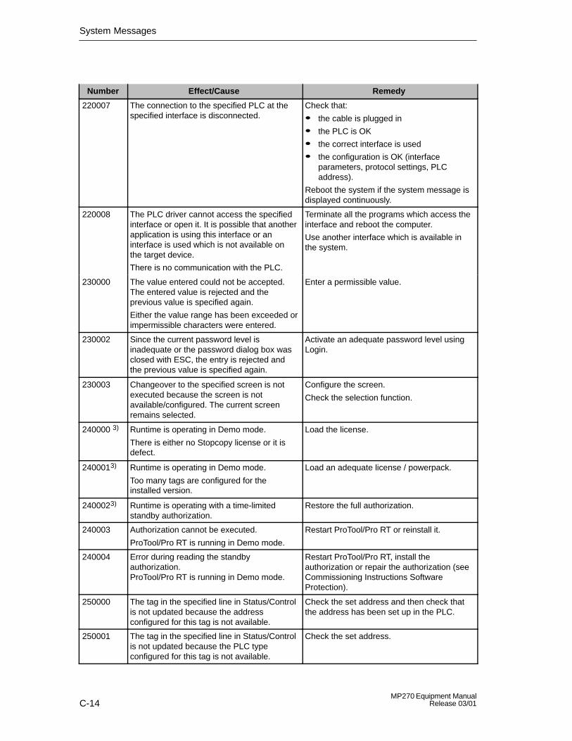
System Messages
C-14MP270 Equipment Manual
Release 03/01
RemedyEffect/CauseNumber
220007 The connection to the specified PLC at thespecified interface is disconnected.
Check that:
� the cable is plugged in
� the PLC is OK
� the correct interface is used
� the configuration is OK (interfaceparameters, protocol settings, PLCaddress).
Reboot the system if the system message isdisplayed continuously.
220008 The PLC driver cannot access the specifiedinterface or open it. It is possible that anotherapplication is using this interface or aninterface is used which is not available onthe target device.
There is no communication with the PLC.
Terminate all the programs which access theinterface and reboot the computer.
Use another interface which is available inthe system.
230000 The value entered could not be accepted.The entered value is rejected and theprevious value is specified again.
Either the value range has been exceeded orimpermissible characters were entered.
Enter a permissible value.
230002 Since the current password level isinadequate or the password dialog box wasclosed with ESC, the entry is rejected andthe previous value is specified again.
Activate an adequate password level usingLogin.
230003 Changeover to the specified screen is notexecuted because the screen is notavailable/configured. The current screenremains selected.
Configure the screen.
Check the selection function.
240000 3) Runtime is operating in Demo mode.
There is either no Stopcopy license or it isdefect.
Load the license.
2400013) Runtime is operating in Demo mode.
Too many tags are configured for theinstalled version.
Load an adequate license / powerpack.
2400023) Runtime is operating with a time-limitedstandby authorization.
Restore the full authorization.
240003 Authorization cannot be executed.
ProTool/Pro RT is running in Demo mode.
Restart ProTool/Pro RT or reinstall it.
240004 Error during reading the standbyauthorization.ProTool/Pro RT is running in Demo mode.
Restart ProTool/Pro RT, install theauthorization or repair the authorization (seeCommissioning Instructions SoftwareProtection).
250000 The tag in the specified line in Status/Controlis not updated because the addressconfigured for this tag is not available.
Check the set address and then check thatthe address has been set up in the PLC.
250001 The tag in the specified line in Status/Controlis not updated because the PLC typeconfigured for this tag is not available.
Check the set address.

System Messages
C-15MP270 Equipment ManualRelease 03/01
RemedyEffect/CauseNumber
250002 The tag in the specified line in Status/Controlis not updated because it is not possible tomap the PLC type in the tag type.
Check the set address.
250003 No connection could be established to thePLC. The tags will not be updated.
Check the connection to the PLC. Check thatthe PLC is switched on and online isactivated.
260000 A password has been entered which isunknown to the system. Therefore, thelowest password level has been set. Thiscorresponds to the status following Logout.
Enter a known password in the passwordinput field (with corresponding level).
260001 A password has been entered whoseassigned level does not permit execution ofthe function.
The password level currently set is displayedfor information purposes.
Modify the password level in the passwordinput field enter a password with a sufficientlyhigh level.
270000 A tag is not displayed in the messagebecause it attempts to access an invalidaddress in the PLC.
Check whether the data area for the tagexists in the PLC, the configured address iscorrect or the value range for the tag iscorrect.
270001 There is a unit-dependent limit as to howmany messages may be queuedsimultaneously in order to be displayed (seeGHB). This limit has been exceeded.
The display no longer contains all themessages.
However, all the messages are recorded inthe message buffer.
–
270002 Messages are displayed from an archive aredisplayed for which there is no data in thecurrent project.
Placeholders are issued for the messages.
Delete older archive files, if necessary.
280000 Connection is re-established because thecause of the interruption has beeneliminated.
–
280001 No more data is read or written.
Possible causes:
� The cable is defective.
� The PLC does not respond, is defective,etc.
� Connection is established via the wronginterface.
� The system is overloaded.
Check that the cable is plugged in, the PLCis operational, the correct interface is used.
Reboot the system if the system message isdisplayed continuously.
280002 A connection is used which requires afunction module in the PLC.
The function block has replied.Communication can now proceed.
–
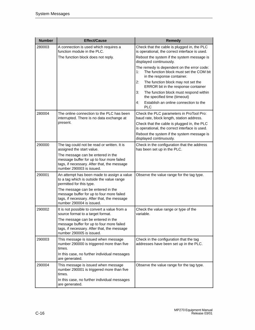
System Messages
C-16MP270 Equipment Manual
Release 03/01
RemedyEffect/CauseNumber
280003 A connection is used which requires afunction module in the PLC.
The function block does not reply.
Check that the cable is plugged in, the PLCis operational, the correct interface is used.
Reboot the system if the system message isdisplayed continuously.
The remedy is dependent on the error code:1: The function block must set the COM bit
in the response container.
2: The function block may not set theERROR bit in the response container
3: The function block must respond withinthe specified time (timeout)
4: Establish an online connection to thePLC
280004 The online connection to the PLC has beeninterrupted. There is no data exchange atpresent.
Check the PLC parameters in ProTool Pro:baud rate, block length, station address.
Check that the cable is plugged in, the PLCis operational, the correct interface is used.
Reboot the system if the system message isdisplayed continuously.
290000 The tag could not be read or written. It isassigned the start value.
The message can be entered in themessage buffer for up to four more failedtags, if necessary. After that, the messagenumber 290003 is issued.
Check in the configuration that the addresshas been set up in the PLC.
290001 An attempt has been made to assign a valueto a tag which is outside the value rangepermitted for this type.
The message can be entered in themessage buffer for up to four more failedtags, if necessary. After that, the messagenumber 290004 is issued.
Observe the value range for the tag type.
290002 It is not possible to convert a value from asource format to a target format.
The message can be entered in themessage buffer for up to four more failedtags, if necessary. After that, the messagenumber 290005 is issued.
Check the value range or type of thevariable.
290003 This message is issued when messagenumber 290000 is triggered more than fivetimes.
In this case, no further individual messagesare generated.
Check in the configuration that the tagaddresses have been set up in the PLC.
290004 This message is issued when messagenumber 290001 is triggered more than fivetimes.
In this case, no further individual messagesare generated.
Observe the value range for the tag type.

System Messages
C-17MP270 Equipment ManualRelease 03/01
RemedyEffect/CauseNumber
290005 This message is issued when messagenumber 290002 is triggered more than fivetimes.
In this case, no further individual messagesare generated.
Check the value range or type of thevariable.
290006 The threshold values configured for the taghave been violated by values entered.
Observe the configured or current thresholdvalue of the tag.
290007 There is a difference between the sourceand target structure of the recipe currentlybeing processed. The target structurecontains an additional data record tag whichis not available in the source structure.
The data record tag specified is assigned itsstart value.
Insert the specified data record tag in thesource structure.
290008 There is a difference between the sourceand target structure of the recipe currentlybeing processed. The source structurecontains an additional data record tag whichis not available in the target structure andtherefore cannot be assigned.
The value is rejected.
Remove the specified data record tag in thespecified recipe from the project.
290010 The storage location configured for therecipe is not permitted.
Possible causes: Impermissible characters, write protected,data medium full or does not exist.
Check the path specification configured.
290011 The data record specified by the numberdoes not exist.
Check the source for the number (constantor variable value).
290012 The recipe specified by the number does notexist.
Check the source for the number (constantor variable value).
290013 An attempt was made to save a data recordunder a data record number which alreadyexists.
The process is not executed.
� Check the source for the number(constant or variable value).
� Delete the data record beforehand.
� Change the function parameter “Overwrite”.
290014 The file specified to be imported could not befound.
� Check the file name.
� Ensure that the file is in the specifieddirectory.
290020 Acknowledgement that downloading of datarecords from operating unit to PLC hasstarted.
–
290021 Acknowledgement that downloading of datarecords from operating unit to PLC has beencompleted without any errors.
–

System Messages
C-18MP270 Equipment Manual
Release 03/01
RemedyEffect/CauseNumber
290022 Acknowledgement that downloading of datarecords from operating unit to PLC has beenterminated due to an error.
Check the configuration:
� have the tag addresses been set up inthe PLC?
� does the recipe number exist?
� does the data record number exist?
� has the function parameters ”Overwrite”?
290023 Acknowledgement that downloading of datarecords from the PLC to the operating unithas started.
–
290024 Acknowledgement that downloading datarecords from the PLC to the operating unithas been completed without any errors.
–
290025 Acknowledgement that downloading of datarecords from the PLC to the operating unithas been terminated due to an error.
Check the configuration:
� have the tag addresses been set up inthe PLC?
� does the recipe number exist?
� does the data record number exist?
� has the function parameters ”Overwrite”?
290026 An attempt has been made to read/write adata record although the data mailbox is notfree at present.
This error may occur in the case of recipesfor which downloading with synchronizationhas been configured.
Set the data mailbox status to zero.
290027 No connection to the PLC can beestablished at present. Therefore, the datarecord can neither be read nor written.
Possible causes: No physical connection to the PLC (no cableplugged in, cable is defect) or the PLC isswitched off.
Check the connection to the PLC.
290030 This message is issued after reselecting ascreen that contains a recipe display inwhich a data record has already beenselected.
Reload the data record from the datamedium or retain the current values.
290031 While saving, it was detected that a datarecord with the specified number alreadyexists.
Overwrite the data record or cancel theprocess.
290032 While exporting data records, it was detectedthat a file with the specified name alreadyexists.
Overwrite the file cancel the process.
290033 Confirmation request before deleting datarecords.
–

System Messages
C-19MP270 Equipment ManualRelease 03/01
RemedyEffect/CauseNumber
290040 A data record error with error code %1 hasoccurred which cannot be described in moredetail.
The action was canceled.
It might be that the data mailbox has notbeen installed correctly on the PLC.
Check that the data carrier, the data record,the data mailbox and, if necessary, theconnection to the PLC.
Trigger the action again after waiting a shortperiod.
If the error occurs again, please contact theCustomer Support. Specify the error codedisplayed.
290041 A data record or file cannot be savedbecause the data medium is full.
Delete files no longer required.
290042 An attempt was made to execute severalrecept actions simultaneously.
The last action was not executed.
Trigger the action again after waiting a shortperiod.
290044 The data store for the recipe has beendestroyed and will be deleted.
–
290050 Acknowledgement that the exportation ofdata records has started.
–
290051 Acknowledgement that the exportation ofdata records has been completedsuccessfully.
–
290052 Acknowledgement that the exportation ofdata records has been terminated due toerrors.
Ensure that the structure of the data recordson the data medium and the current recipestructure on the operating unit are identical.
290053 Acknowledgement that the importation ofdata records has been started.
–
290054 Acknowledgement that the importation ofdata records has been completedsuccessfully.
–
290055 Acknowledgement that the importation ofdata records has been terminated due toerrors.
Ensure that the structure of the data recordson the data medium and the current recipestructure on the operating unit are identical.
290056 The value in the specified line/column couldnot be read/written without errors.
The action was canceled.
Check the specified line/column.
290057 The tags of the recipe specified have beenswitched from operating mode “offline” to“online”.
Each modification of a tag in this recipe isnow immediately transferred to the PLC.
–
290058 The tags of the recipe specified wereswitched from operating mode “online” to“offline”.
Modifications to tags in this recipe are nolonger immediately transferred to the PLCbut must be transferred there explicitly bymeans of downloading a data record, ifnecessary.
–
290059 Acknowledgement that the specified datarecord has been stored successfully.
–

System Messages
C-20MP270 Equipment Manual
Release 03/01
RemedyEffect/CauseNumber
290060 Check-back message that the data recordmemory has been successfully erased.
–
290061 Check-back message, that erasing the datarecord memory was aborted with errors.
–
300000 Process monitoring (e.g. using PDiag orS7-Graph) has been incorrectlyprogrammed: More messages are queuedthan specified in the technical data of theCPU. No further ALARM_S messages canbe managed by the CPU and reported tooperating systems.
Change the CPU configuration.
310000 An attempt is being made to print too manyprotocols simultaneously.
Since only one protocol can be printed at atime, the print job is rejected.
Wait until printout of the last active protocolhas been concluded.
Repeat the print job, if necessary.
310001 An error occurred on triggering the printer.The protocol is either not printed or printedwith errors.
Evaluate the additional system message,related to this message, which is also issued.
Repeat the print job, if necessary.
320000 The movements have already been indicatedby another device.
The movements can no longer be served.
Select the movements on the other displayunits and select the movement screen on therequired display unit.
320001 The network is too complex.
The defective operands cannot be displayed.
Display the network in AWL.
320002 No diagnostics-capable alarm messageshave been selected.
The units related to the alarm messagescould not be selected.
Select a diagnostics-capable alarm messagein the message screen ZP_ALARM.
320003 No alarm messages exist in respect of theselected unit.
No network can be displayed in the detaildisplay.
Select the defective unit in the general viewscreen.
320004 The required signal statuses could not beread by the PLC.
The defective operands cannot beestablished.
Check the consistency between theconfiguration on the display unit and the PLCprogram loaded.
320005 The project contains ProAgent partitionswhich are not installed.
No ProAgent diagnostics can be performed.
In order to run the project, install theProAgent option packet.
1) The optional parameter %1 at the start of the message may contain an identification for the S7 connectionwhen several S7s are in parallel operation and are connected to diagnostics equipment.
2) A WinCC channel provides the message texts via an interface. This text is issued via this message.ProTool/Pro RT has no influence on this texts.
3) The specified text comes from the component resources.

System Messages
C-21MP270 Equipment ManualRelease 03/01
Procedure in the case of “internal errors”
Please proceed as follows in the case of all system messages related to “internalerrors”:
1. Start up the operating unit again.
2. Download the configuration again.
3. Switch the operating unit off, stop the PLC and then restart both.
4. If the error occurs again, please contact the SIMATIC Customer Support. Makereference to the specified error number and message tags.

System Messages
C-22MP270 Equipment Manual
Release 03/01

D-1MP270 Equipment ManualRelease 03/01
ESD Guidelines
What does ESD mean?
Virtually all present-day modules incorporate highly integrated MOS devices orcomponents. For technological reasons, these electronic components are verysensitive to overvoltages and consequently therefore to electrostatic discharge:
These devices are referred to in German as Elektrostatisch GefährdetenBauelemente/ Baugruppen: ”EGB”
The more frequent international name is:
”ESD” (Electrostatic Sensitive Device)
The following symbol on plates on cabinets, mounting racks or packages drawsattention to the use of electrostatic sensitive devices and thus to the contactsensitivity of the assemblies concerned:
ESDs may be destroyed by voltages and energies well below the perceptionthreshold of persons. Voltages of this kind occur as soon as a device or anassembly is touched by a person who is not electrostatically discharged . Devicesexposed to such overvoltages cannot immediately be detected as defective in themajority of cases since faulty behavior may occur only after a long period ofoperation.
Precautions against electrostatic discharge
Most plastics are capable of carrying high charges and it is therefore imperativethat they be kept away from sensitive components.
When handling electrostatic sensitive devices, make sure that persons, workplacesand packages are properly grounded.
D

ESD Guidelines
D-2MP270 Equipment Manual
Release 03/01
Handling ESD assemblies
A general rule is that assemblies should be touched only when this cannot beavoided owing to the work that has to performed on them. Under no circumstancesshould you handle printed-circuit boards by touching device pins or circuitry.
You should touch devices only if
� you are grounded by permanently wearing an ESD wrist strap or
� you are wearing ESD shoes or ESD shoe-grounding protection straps inconjunction with an ESD floor.
Before you touch an electronic assembly, your body must be discharged. Thesimplest way of doing this is to touch a conductive, grounded object immediatelybeforehand – for example, bare metal parts of a cabinet, water pipe etc.
Assemblies should not be brought into contact with charge-susceptible and highlyinsulating materials such as plastic films, insulating table tops and items of clothingetc. containing synthetic fibers.
Assemblies should be deposited only on conductive surfaces (tables with an ESDcoating, conductive ESD cellular material, ESD bags, ESD shipping containers).
Do not place assemblies near visual display units, monitors or television sets(minimum distance to screen > 10 cm).
Measuring and modifying ESD assemblies
Perform measurements on ESD assemblies only when
� the measuring instrument is grounded – for example, by means of a protectiveconductor – or
� the measuring head has been briefly discharged before measurements aremade with a potential-free measuring instrument – for example, by touching abare metal control cabinet.
When soldering, use only grounded soldering irons.
Shipping ESD assemblies
Always store and ship assemblies and devices in conductive packing – forexample, metallized plastic boxes and tin cans.
If packing is not conductive, assemblies must be conductively wrapped before theyare packed. You can use, for example, conductive foam rubber, ESD bags,domestic aluminum foil or paper (never use plastic bags or foils).
With assemblies containing fitted batteries, make sure that the conductive packingdoes not come into contact with or short-circuit battery connectors. If necessary,cover the connectors beforehand with insulating tape or insulating material.

E-1MP270 Equipment ManualRelease 03/01
SIMATIC HMI Documentation
Target groups
This manual is part of the SIMATIC HMI documentation. The documentation isaimed at the following target groups:
� Newcomers
� Users
� Configurers
� Programmers
� Commissioning engineers
How the documentation is organized
The SIMATIC HMI documentation consists of the following components:
� User’s Guides for:
– Configuration software
– Runtime software
– Communication between PLCs and operating units
� Equipment Manuals for the following operating units:
– SIMATIC PC
– MP (Multi Panel)
– OP (Operator Panel)
– TP (Touch Panel)
– TD (Text Display)
– PP (Push Button Panel)
� Online Help on the configuration software
� Start-up Guides
� First Steps
Overview of complete documentation
The following table provides an overview of the SIMATIC HMI documentation andshows you when you require the different documents.
E

SIMATIC HMI Documentation
E-2MP270 Equipment Manual
Release 03/01
Documentation Target Group Content
First Steps with ProTool
Product Brief
Newcomers This documentation guides you step by step throughthe configuration of
� a screen with various objects
� changing from one screen to another
� a message.
This documentation is available for:
� Text-based Displays
� Graphics Displays
� Touch Panels
� Windows-based Systems
ProToolConfiguring Windows-based Systems
User’s Guide
Configurers Provides information on working with the configurationsoftware. It contains
� information on installation
� basic principles of configuration
� a detailed description of configurable objects andfunctions.
This documentation is valid for Windows-basedsystems.
ProToolConfiguring Graphics Displays
User’s Guide
Configurers Provides information on working with the configurationsoftware. It contains
� information on installation
� basic principles of configuration
� a detailed description of configurable objects andfunctions.
This documentation is valid for graphic displayoperating units.
ProToolConfiguring Text-based Displays
User’s Guide
Configurers Provides information on working with the configurationsoftware. It contains
� information on installation
� basic principles of configuration
� a detailed description of configurable objects andfunctions.
This documentation is valid for text-based displayoperating units.
ProTool
Online Help
Configurers Provides information on the configuration computerwhile working with ProTool. Online Help contains
� context-sensitive help
� detailed instructions and examples
� detailed information
� all the information from the user guide.
ProTool/Pro Runtime
User’s Guide
Commissioningengineers, Users
Provides information on working with ProTool/ProRuntime software. It contains
� installation of the ProTool/Pro Runtime visualizationsoftware
� commissioning and running the software onWindows-based systems.

SIMATIC HMI Documentation
E-3MP270 Equipment ManualRelease 03/01
ContentTarget GroupDocumentation
Copy Protection
Start-up Guide
Commissioningengineers, Users
The ProTool/Pro Runtime visualization software is acopyright product. This manual contains information onthe installation, repair and uninstallation ofauthorizations.
Application Example
Start-up Guide
Newcomers ProTool is supplied with example configurations andthe corresponding PLC programs. This documentationdescribes how you
� load the examples onto the operating unit and PLC
� run the examples and
� upgrade the connection to the PLC to suit your ownspecific application.
SIMATIC Panel PC 670
Equipment Manual
Commissioningengineers, Users
Describes the computer unit and operating unit of theSIMATIC Panel PC 670.
MP370Equipment Manual
MP270Equipment Manual
TP170 A, TP170 B,OP170 BEquipment Manual
TP070Equipment Manual
Commissioningengineers, Users
Describes the hardware and the general operation ofWindows-based Panels:
� installation and commissioning instructions
� a description of the equipment
� operating instructions
� instructions for connecting the PLC, printer andprogramming computer,
� maintenance instructions.
OP37/ProEquipment Manual
Commissioningengineers, Users
Describes the hardware, installation and inclusion ofupgrades and options for the OP37/Pro.
TP27, TP37Equipment Manual
OP27, OP37Equipment Manual
OP25, OP35, OP45Equipment Manual
OP7, OP17Equipment Manual
OP5, OP15Equipment Manual
TD17Equipment Manual
Commissioningengineers, Users
Describes the hardware and general operation. It contains
� installation and commissioning instructions
� a description of the equipment
� instructions for connecting the PLC, printer andprogramming computer,
� operating modes
� operating instructions
� description of the standard screens supplied withthe operating unit and how to use them
� fitting options
� maintenance and fitting of spare parts.
OP3
Equipment Manual
Commissioningengineers, Users, Programmers
Describes the hardware of the OP3, its generaloperation and the connection to the SIMATIC S7.
PP7, PP17
Equipment Manual
Commissioningengineers, Users
Describes the hardware, installation andcommissioning of push-button panels PP7 and PP17.
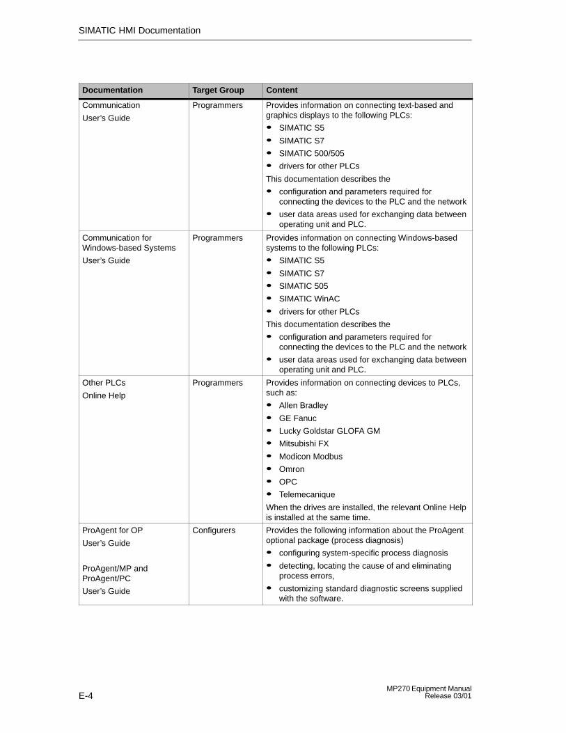
SIMATIC HMI Documentation
E-4MP270 Equipment Manual
Release 03/01
ContentTarget GroupDocumentation
Communication
User’s Guide
Programmers Provides information on connecting text-based andgraphics displays to the following PLCs:
� SIMATIC S5
� SIMATIC S7
� SIMATIC 500/505
� drivers for other PLCs
This documentation describes the
� configuration and parameters required forconnecting the devices to the PLC and the network
� user data areas used for exchanging data betweenoperating unit and PLC.
Communication for Windows-based Systems
User’s Guide
Programmers Provides information on connecting Windows-basedsystems to the following PLCs:
� SIMATIC S5
� SIMATIC S7
� SIMATIC 505
� SIMATIC WinAC
� drivers for other PLCs
This documentation describes the
� configuration and parameters required forconnecting the devices to the PLC and the network
� user data areas used for exchanging data betweenoperating unit and PLC.
Other PLCs
Online Help
Programmers Provides information on connecting devices to PLCs,such as:
� Allen Bradley
� GE Fanuc
� Lucky Goldstar GLOFA GM
� Mitsubishi FX
� Modicon Modbus
� Omron
� OPC
� Telemecanique
When the drives are installed, the relevant Online Helpis installed at the same time.
ProAgent for OP
User’s Guide
ProAgent/MP andProAgent/PC
User’s Guide
Configurers Provides the following information about the ProAgentoptional package (process diagnosis)
� configuring system-specific process diagnosis
� detecting, locating the cause of and eliminatingprocess errors,
� customizing standard diagnostic screens suppliedwith the software.
Glossary-1MP270 Equipment ManualRelease 03/01
Glossary
Acknowledgement
Acknowledgement of an alarm message on the operating unit confirms that it hasbeen noted. After acknowledgement, the message disappears from the operatingunit. Alarm messages can be acknowledged either on the operating unit or PLC.Alarm messages can be compiled into groups so that several messages can beacknowledged simultaneously.
Acknowledgement groups
During configuration, several alarm messages can be compiled to form anacknowledgement group. After acknowledging the first message, all the othermessages belonging to the same group are simultaneously acknowledged. Thisenables, for example, acknowledgement of alarm messages for the cause of afault and all resulting faults (group acknowledgement).
Alarm message
Provides information on the operating unit concerning operating errors on themachine or system connected to the PLC. The message text may also containcurrent measured values.
Since alarm messages indicate abnormal operating status, they must beacknowledged.
ALARM_S
Active message procedure by which the CPU issued messages to all theregistered network participants. ALARM_S messages are configured in STEP 7.
Analog display
A screen object which displays numeric values by means of a pointer instrument.

Glossary
Glossary-2MP270 Equipment Manual
Release 03/01
Archive
A memory area on a data storage medium in which messages or tags can bestored. The size of the archive is defined in ProTool/Pro CS.
Area pointer
Defines a memory area in the PLC for data exchange between the PLC andoperating unit.
Bar graphs
Represent values from the PLC as rectangular areas. This is a way of displayingfilling levels or workpiece numbers, for example, on the operating unit.
Baud rate
Rate of speed at which data is downloaded. Baud rate is specified in Bit/s.
Blanking circuit
Switch off or dim the screen back-lighting.
Boot
A loading process which downloads the operating system in the working memoryof the operating unit
Buttons
A virtual button on the operating unit screen. Buttons on operating units with touchscreens are contact sensitive.

Glossary
Glossary-3MP270 Equipment ManualRelease 03/01
Clicking
Configurable event which can trigger a function assigned to a button, for example,when the button is pressed and released (clicked) within the contour of the button.
If the button is pressed using the mouse button or finger (when using touch panels)but moved outside the contour before releasing, the operating unit does notinterpret the action as a click event.
Clock
Screen object which displays the system time either as digits (digitally) or in theform of a clock (analog).
Combo box
Contains a list of entries from which one can be selected on the operating unit.
Configuration
Definition of basic, system-specific settings, messages and screens using theProTool CS configuration software.
Data record
A recipe containing data. A recipe can be comprised of several data records.When a data record is downloaded, all the assigned data is transferred to the PLCtogether and synchronously.
Display message
A screen object with configurable filter criteria which is used to display the volatilemessage buffer or message archive.
Display period
Defines whether and how long a system message is displayed on the operatingunit.
Glossary
Glossary-4MP270 Equipment Manual
Release 03/01
Download
The transfer of run-capable project data to the operating unit. Connect theoperating unit to the configuration computer with a standard cable beforehand.
Download mode
Operating unit operating mode in which data can be downloaded from theconfiguration computer to the operating unit (also refer to Download).
Event
Functions are triggered by the arrival of defined events. Events can be configuredaccording to the object. Events which can be configured for a button include:
� Click
� Press
� Release
Event message
Provides information on the operating unit concerning the operating statuses of themachine or system connected to the PLC. The message text may also containcurrent measured values.
Fixed window
Window which always appears at the top of the operating unit screen. The contentof the fixed window is independent of the screen currently open.
Flash memory
Programmable memory which can be electrically deleted and written to againsegment-by-segment.
Function key
Key on the operating unit to which a configurable function can be assigned. Afunction key with a global function assignment always initiates the same functionregardless of the screen currently open. A function key with a local functionassignment (softkey) can have a different function for each screen.

Glossary
Glossary-5MP270 Equipment ManualRelease 03/01
Global tag
This is a process tag linked to the PLC. Global tags have a fixed address in thePLC. The operating unit accesses this address for reading and writing purposes.
Graphics list
A list in which each value relates to a tag assigned to a graphic. This enables, forexample, the assigned graphic to be displayed on the operating unit output fieldinstead of the value.
Group acknowledgement
During the configuration, each alarm message can be assigned to anacknowledgement group. When the alarm message is acknowledged, all theother alarm messages in the same group are simultaneously acknowledged.
Half Brightness Life
Time period after which the brightness of the lighting tube only achieves 50% of itsoriginal value.
Hardcopy
Represents a printout of the current screen content. Windows called in on top arenot printed.
Help text
Configurable, additional information on messages, screens and fields. The helptext concerning an alarm message can, for example, contain information on thecause of the fault and methods of elimination.
History trend
After setting a trigger bit that reads all the trend values simultaneously from thePLC, they are displayed as a history trend on the operating unit. History trends arewell suited for displaying distinct changes in a trend when the progress of a trendcurve is of more interest with regard to its full course (history) than to the individualvalues.

Glossary
Glossary-6MP270 Equipment Manual
Release 03/01
Icon
Pixel graphic of a fixed size, e.g. assigned to a softkey, to identify its function.
Input field
Enables the user to enter values which are subsequently downloaded to the PLC.
Invisible buttons
Buttons which are only visible during configuration, not on the operating unit. Ifinvisible buttons are superimposed on components in the process screen, therespective components can be operated by clicking the button with the mouse orpressing them on the touch screen.
Limit value
Configurable values of a tag defining a value range. Attempts to define valuesoutside these limits, may cause the following effects on the operating unit:
� Input fieldinput is rejected
� Output fieldvalues are displayed in the configured color
� Trend/Barvalues are displayed in the configured color
Local tag
A tag without a link to the PLC. Local tags are only available on the operating unit.
Logout time
Configurable interval of time after which the password level is reset to zero whenthe operating unit is not used.

Glossary
Glossary-7MP270 Equipment ManualRelease 03/01
Message arrival
Time at which a message was triggered by the PLC or operating unit.
Message buffer
Memory area in the operating unit in which message events can be stored inchronological order as they arrive. Event messages and alarm messages arestored in separate message buffers.
Message departure
Time at which a message was withdrawn by the PLC.
Message events
These are stored in chronological order in the operating unit message archive.Message events consist of:
� Message arrival
� Message acknowledgement
� Message departure
Message indicator
A configurable graphical symbol displayed on the operating unit when at least onealarm message is present.
Message logging
Printout of messages parallel to their display on the operating unit display.
Message view
Screen object to display the volatile message buffer and/or message archive.
Multi Panel
Multi-purpose, configurable operating unit with graphic display and Windows CEoperating system for operating and monitoring machines and systems.

Glossary
Glossary-8MP270 Equipment Manual
Release 03/01
Normal operation
Operating unit operating mode in which messages are displayed and screens canbe operated.
Object
Is a component part of a screen or message. Depending on the object type,objects serve to display or enter texts and values on the operating unit.
Operator Panel
Configurable operating unit for operating and monitoring machines and systems.
Output field
Displays current values from the PLC on the operating unit.
Password
A character string which must be entered on the operating unit before a protectedfunction can be activated. Each password is assigned to a defined passwordlevel.
Password level
The rights to use operating units can be specifically restricted to certain users anduser groups. To do this, the individual functions and operating elements areassigned to hierarchically defined password levels. The password level linked tothe password allocates the rights to execute functions on the operating unitbelonging to that level or lower.

Glossary
Glossary-9MP270 Equipment ManualRelease 03/01
Password list
A screen object for entering passwords related to different authorization levels.
PCL
Hewlett Packard printer language (Printer Control Language).
PLC
General term for units and systems with which the operating unitcommunicates (e.g. SIMATIC S7 or PC).
PLC job
PLC jobs can be used by the PLC to trigger functions on the operating unit, e.g.display a screen.
Power-up test
Checks the status of the CPU and memory each time the power is switched on.
Press
Configurable event which may trigger a function assigned to a button, for example,as the button is pressed.
Print screen
Printout of a copy of the screen contents.
Process screen
The display of process values and process progress on the operating unit in theform of screens, which may contain graphics, texts and values.
Programmable controller
PLC from the SIMATIC S5 series (e.g. AG S5-115U/135U).
Programmable system
PLC from the SIMATIC S7 series (SIMATIC S7-200/300/400).
ProTool
Full-graphic configuration software for configuring text displays, text-based andgraphics operator panels as well as units from the Windows CE range, such asTP170/OP170/MP270/MP370.

Glossary
Glossary-10MP270 Equipment Manual
Release 03/01
ProTool CS
General name for the three configuration software variants ProTool/Pro CS,ProTool and ProTool/Lite.
ProTool/Lite
Full-graphic configuration software for configuring text displays and text-basedoperator panels, as well as WindowsCE-based units in the 170er product range,such as TP170 A.
ProTool/Pro CS
Full-graphic configuration software for configuring the entire SIMATIC HMI productrange and Windows-based systems.
Queued messages
Messages which have been detected as having been received by the operatingunit (message event Arrived) but for which the message event Departed has stillnot occurred.
Recipe
A combination of tags to a fixed data structure. The data structure configured canbe assigned data on the operating unit and is then referred to as a data record.The use of recipes ensures that when a data record is downloaded, all theassigned data is transferred to the PLC together and synchronously.
Recipe view
Screen object to create, edit, store and download data records.
Release
Configurable event which may trigger a function assigned to a button, for example,as the button is released.

Glossary
Glossary-11MP270 Equipment ManualRelease 03/01
Remaining buffer
Configurable size of the message buffer. In the case of a buffer overflow, theoperating unit deletes message events until the configured remaining buffercapacity is reached.
RS232
Standard interface for serial data transmission with defined voltage levels. Senderand receiver are electrically connected.
RS485
Standard interface for serial data transmission with very high transmission rates.
Runtime software
The program visualization software SIMATIC ProTool/Pro RT with which the projectcreated using ProTool CS can be run on your Windows-based system.
Screen
A screen displays all the logically related process data on the operating unit,whereby the individual values can be modified. Screens are composed of staticand dynamic parts. Static parts refer to text and graphics, dynamic parts to inputand output fields.
Selection field
Contains a list of entries from which one can be selected on the operating unit.
Slider controls
Screen object for entering and displaying numeric values in analog form.
Softkey
Function key on the operating unit with a local function assignment. The functiontriggered by a softkey varies according to the screen currently open.
Glossary
Glossary-12MP270 Equipment Manual
Release 03/01
Start screen
The first screen which automatically appears after the operating unit has startedup.
Status button
A status button is a display and operating element with two possible states: ONand OFF, i.e. touched and untouched. Both states can be configured for displaywith text or graphics, which then label the status button.
Status/Force tag
Screen object which enables direct read and write access from the operating unitto individual address areas in the connected SIMATIC S5 or SIMATIC S7.
STEP 7
Programming software for SIMATIC S7, SIMATIC C7 and SIMATIC WinAC.
Superuser
A user with permissions to trigger functions of the highest password level. Thesuperuser has access to all the operating unit functions.
Switch
A screen object for entering and displaying a binary status. A switch can only be inthe status on or off .
System message
Provides information on the operating unit concerning internal statuses of theoperating unit and PLC.

Glossary
Glossary-13MP270 Equipment ManualRelease 03/01
Trend curve
Curve type by which just one curve value is read from the PLC per cycle or triggerresulting in a curve display. If the configured number of measured values is notachieved, each new value overwrites the oldest value. Trend curves are especiallysuited to displaying continual progress.
Trend view
Screen object providing a clear, continuous display of process data. Severaldifferent curves can be displayed simultaneously in the trend view, e.g. in the formof trend curves or history trends.
TTY
Standard interface for serial data transmission with defined current levels. Senderand receiver are electrically isolated.

Glossary
Glossary-14MP270 Equipment Manual
Release 03/01

Index-1MP270 Equipment ManualRelease 03/01
Index
AAcknowledge, Key, 4-4Acknowledgement, alarm message, 5-20, 5-23Acknowledging, Alarm message, 5-16Acknowledgment groups, 2-1Air discharge, A-5Alarm message buffer, example, 5-22Alarm message page, 5-21Alarm messages, 5-3, 5-16, 5-19
acknowledge, 5-20, 5-23Acknowledging, 5-16
ALARM_S, 2-1, 5-18Alignment, printer, 8-8Alphanumeric input field, 5-9Alphanumeric key assignment, 4-3ALT, key, 4-4Ambient conditions, A-4Analog clock, 5-32Analog display, 5-8, 5-29Analog/Digital clock, 5-8Angle of inclination, 9-2, A-4Apply, Status/Force, 5-37Approvals, A-6Archive functions, 7-2Archive_tag, function, 7-2Archives, 7-1Archiving, 2-3Area of use, 1-2Arrangement, connection elements, 9-5AS511, 2-4ASCII character set, Printer, 9-11Assignment of interfaces, B-1Authorization, 5-33
password protection, 5-33Automatic downloading, 3-5
BBack–lighting
off, 5-4Screen, 1-4, A-2
Backup, 3-15
Backup battery, 5-30, 9-5, 11-2, A-3Changing, 12-2
Bar graph, 5-8Bar graphs, 5-25Barometric pressure, A-4Battery, 5-30, 11-2, A-3
Changing, 12-2Baud rate
download mode, 3-9printer, 8-8
Bit triggering, 5-26Blanking, screen, 2-3Border, 3-2Bracket, memory card, 11-4Brightness
Screen, 2-3Set, 4-6, 8-4
Buffer overflow, Messages, 5-17Buffering, Messages, 5-16Burst interference, A-5Button, 5-7
Apply (Status/Force), 5-37Message view, 5-23Messages, 5-20Status/Force, 5-36Update (Status/Force), 5-37
Buttonshidden, 5-12Trends, 5-26
Buttons , 5-12
CCable cross–section, 9-7Cables, 9-4Calendar dates, 5-30Call, screen, 5-4Cancel
Download, 4-6Key, 4-3
Capacitybackup battery, A-3
Index
Index-2MP270 Equipment Manual
Release 03/01
Message buffer, 2-1CF card, 6-3, 6-11Change
data record, 6-12Language, 8-2recipe structure, 6-21
Change of status, event, 5-13, 5-15Change structure, recipe, 6-21Change window, 5-3Change_Data_Record_Number_To_Name,
function, 6-15Change_mode, Function, 8-3Changing, Battery, 12-2Changing active window, 5-3Character set, Printer, 9-11Check, Limit value, 4-10, 5-9Circle, 5-7Clean, Unit, 12-1Cleaning agents, 12-1Clear_message_buffer, Function, 5-17Clicking , event, 5-12Clock, 5-8, 5-32
Internal, 11-2Close, dialog, 4-7Close_archive, function, 7-2Color change, 3-2
Input field, 4-9input field, 5-10trend view, 5-26
Colors, 1-4, A-2Commissioning, 3-1Communication, 2-4Compact Flash Card, 11-3, A-2Compatibility, cursor control, 4-7Compatibility conflict, 3-3, 3-4, 13-1Compress
project file, 3-13PU function, 9-10trend view, 5-27
Condensation, 9-2Conduction, RF, A-5Configuration computer, Connect, 9-8Configuration menu, 3-7Configuration phase, 1-3Configuration software, 1-3, 1-5Configure, Interface IF1B, 9-10Confirm entry, key, 4-4Conflict, compatibility, 3-3, 3-4, 13-1
ConnectConfiguration computer, 9-8PLC, 9-9Printer, 9-11
ConnectingMP270, 9-4Power supply, 9-7
ConnectionStatus/Force, 5-36to configuration computer, 9-8To PLC, 9-9to PLC, 8-3To printer, 9-11
Connection elements, 9-5, 9-6Connections, Electrical, 9-4Connector pin–out, B-1Contact discharge, A-5Contour, 5-12Contrast, 2-3
Set, 4-6, 8-4Control Panel, 8-5Conventions, Date/Time, 5-30Conversion functions, 2-3Copy, data records, 6-11Create
data record, 6-10Labeling strips, 10-4
Cross–section, Power supply, 9-7CSV file, 6-18, 6-19, 7-1CTRL, key, 4-4Cursor, Key, 4-4Cursor control, compatibility, 4-7Cut–out, Installation, A-2Cycle triggering, 5-26Cyclic archive, 7-3
DData, Technical, A-1Data record
change, 6-12copy, 6-11create, 6-10definition, 6-1, 6-2downloading, 6-14, 6-15editing, 6-6import, 6-21

Index
Index-3MP270 Equipment ManualRelease 03/01
memory requirements, 6-5number, 6-4renaming, 6-13save, 6-10save as, 6-13
Data recordsdeleting, 6-13display, 6-10editing, 6-20export/import, 6-18exporting, 6-20importing, 6-20read from PLC, 6-14
Data structure, 6-2Data type, Status/Force, 5-36Data_Record_DAT_to_PLC, function, 6-17Data_Record_PLC_to_DAT, function, 6-17Data_Record_PLC_to_Tags, function, 6-15Data_Record_Tag_to_PLC, function, 6-15Date, 3-3, 5-9, 5-30
synchronization, 5-31Date/Time, 5-6, 8-6DB number, Status/Force, 5-36Decompress, project file, 3-13Default settings, printer, 8-8Degree of protection, 1-2, 9-2, A-2Delete
data records, 6-13Key, 4-4key, 4-3Messages, 5-17messages, 5-17On buffer overflow, 5-17password, 5-35
Delete_archive, function, 7-2Delete_Data_Record_Memory, functions, 6-15Depth, Installation, A-2Description, unit , 10-1Diagnostics messages, 5-17Dialog, close, 4-7Digital/Analog clock, 5-8, 5-32DIL switch, 9-5, 9-10Dim, screen, 5-4Dimensions, 10-2, A-2Discharge, Static, A-5Display, 1-4, A-2
analog, 5-28data records, 6-10date/time, 5-30messages, 5-17numeric values, 5-28, 5-29Set brightness, 8-4
Set contrast, 8-4time, 5-30, 5-32
Display elementanalog display, 5-29date/time, 5-30digital/analog clock, 5-32message view, 5-23output field, 5-6status button, 5-13
Display elementsbar graphs, 5-25Recipe display, 6-8trend view, 5-26
Display fill level, 5-25Display priorities, Messages, 5-19Display_event_message_window, Function,
5-20DNS server, 8-9Documentation, E-1Download
download back , 3-13Operating mode, 8-3options, 3-7start automatically, 3-5start manually, 3-4TeleService, 1-1
Download back , 3-13Download mode, 3-4Downloading
data records to PLC, 6-14minimizing transfer times, 3-6
Downloading via MPI, 3-5Duration of display, 5-20Dynamic labeling, 5-12Dynamic screen partitions, 5-2
EEdit
data records, 6-6, 6-20messages, 5-20, 5-23
Editing mode, key, 4-3Electrical connections, 9-4Electrical Installation, 9-4Ellipse, 5-7EMC–compatible installation, 9-4Enter
alphanumeric values, keyboard unit, 4-11Numeric values, 4-10numeric values, 5-28password, 5-35

Index
Index-4MP270 Equipment Manual
Release 03/01
special characters, 4-5Enter alphanumeric values, keyboard unit, 4-11Enter numeric values, 4-10Enter symbolic value, 5-11Entering
password, 5-33Values, 4-9
Entering values, 4-9Entry name, 6-2ESC/P compatible, 9-11ESD Guidelines, D-1Ethernet, 8-9Event message screen, 5-21Event messages, 5-3, 5-16, 5-20Events, 5-12, 5-13, 5-15Example
Date/Time, 5-30recipe, 6-2
Exchange, Labeling strips, 10-3Exit_runtime, function, 7-3Expand
memory, 11-3trend view, 5-27Trends, 5-27
Exportdata record, 6-18data records, 6-20password list, 5-35
Export_Data_Records, function, 6-17External dimensions, A-2
FFile, Labeling strips, 10-4File format, CSV, 6-18Filter criteria, Message view, 5-23Fixation, 9-3Fixed window, 5-2Flash memory, 6-3, 6-11
backup, 3-16Backup/Restore, 3-15restore, 3-16
FlashingLED, 4-3messages, 5-19
FM Approval, A-6Foil, Labeling strips, 10-4Force, Status/Force, 5-8Force value, 5-37Format
archive file, 7-1Date/Time, 5-30
Paper, 8-8Status/Force, 5-36
Front panel, Thickness, 9-2, 10-2Front view, 10-2Function
Data_Record_PLC_to_Tags, 6-15Data_Record_Tag_to_PLC, 6-15Load_Data_Record, 6-15Save_Date_Record, 6-15
Function keys, 1-4, 4-2Label, 10-3LED, 4-3
Functionality, 2-1Functions
Archive_tag, 7-2Change_Data_Record_Number_To_Name,
6-15Change_mode, 8-3Clear_message_buffer, 5-17Close_archive, 7-2Data_Record_DAT_to_PLC, 6-17Data_Record_PLC_to_DAT, 6-17Delete_archive, 7-2Delete_Data_Record_Memory, 6-15Display_event_message_window, 5-20Exit_runtime, 7-3Export_Data_Records, 6-17, 6-18, 6-20Go_to_End, 4-8Go_to_Home, 4-8Import_Data_Records, 6-17, 6-18, 6-20Import_export_passwords, 5-35Language, 8-2Login_user, 5-5Logoff_user, 5-5, 5-34Open_archive, 7-2Page_Down, 4-8Page_Up, 4-8Show_alarm_message_buffer, 5-22Show_alarm_message_page, 5-21Show_event_message_buffer, 5-22Show_event_message_page, 5-21Start_archive, 7-2Start_sequence_archive, 7-2Steuerung_verbinden_trennen, 5-18Stop_archive, 7-2
Fuse, A-3FWD files, 3-13
GGeneral operation, 4-1Global function keys, 4-2

Index
Index-5MP270 Equipment ManualRelease 03/01
Go_to_End, function, 4-8Go_to_Home, function, 4-8Graphic, 5-6Graphics list, 5-6Grounding, 9-4Grounding connection, 9-4, 9-5Grounding screw, 9-4Group acknowledgement, 2-1, 4-4Guidelines, EEC, A-5
HHardcopy, 2-2, 4-2Hazardous area, A-6Help text, 2-3
Call, 4-12Display (key), 4-4messages, 5-20, 5-23
Hidden buttons, 5-12Hierarchy, Password, 5-33Home position, Status button, 5-13Housing, A-2Humidity, A-4
IIcon, 4-2Icons, 5-2IF1A interface, Assignment, B-1IF1B interface, Assignment, B-1IF2 interface, Assignment, B-2Import
data record, 6-18data records, 6-20password list, 5-35
Import_Data_Records, function, 6-17Import_export_passwords, function, 5-35Increase
Brightness, 8-4Contrast, 8-4
Initial startup, 3-3Initial value, tags, 6-21Input field, 5-6, 5-9Insert, key, 4-3Installation, 9-1
Configuration computer, 9-8Electrical, 9-4in 19, 9-3In front panels, 9-3Mechanical, 9-2memory card, 11-4
network card, 11-4PLC, 9-9Printer, 9-11
Installation conditions, 9-2Installation dimensions, 19” cabinets, 9-3Installation location, 1-2, 9-2Interface assignment, B-1Interfaces, 1-4, 9-5
Configure IF1B, 9-10IF1A, 9-9IF1B, 9-9IF2, 9-8
Interference–free, 9-4Interrupt, Trends, 5-27Introduction, 1-1Invisible buttons, 5-7Irradiation, RF, A-5Isolation, Electrical, 9-7
KKey, Status button, 5-13Key combination
general operation, 4-6special characters, 4-5
Key combinations, navigation in the operatingsystem, 4-7
Keyboard, 1-4, 4-1, A-3Keypads, 4-1
LLabeling
buttons, 5-12Function keys, 1-4, 10-3
Labeling strips, 9-2Exchange, 10-3
Landscape, printer, 8-8Language
Function, 8-2Set, 8-2System messages, C-1
Language change, 2-3, 8-2Language setting, 8-7Language–dependent objects, 8-2LCD type, A-2LED, 4-12
Acknowledge, 4-4, 5-16Help text, 4-4Shift, 4-3
LED assignment, 4-3

Index
Index-6MP270 Equipment Manual
Release 03/01
LEDs, function keys, 4-3Length, message text, 2-1Level, Password, 5-33Limit value check, 4-10, 5-9Limit value monitoring, 2-2Limit values, Trend view, 5-26Line, 5-7List, passwords, 5-33Literature, 1-5, E-1Lithium battery, A-3
Warning note, 12-3Load, project data, 3-3Load_Data_Record, function, 6-15Local function keys, 4-2Location, A-4Log on, 5-33Logging off, 5-34Login, 5-5, 5-33Logoff, 5-5Logoff_user, Function, 5-5, 5-34Logout, 5-34Logout time, 5-5, 5-34Low–voltage, 9-7
MMaintenance, 12-1Management, passwords, 5-34Manual download, 3-4Margin, printer, 8-8Marking, Input field, 4-9Maximum value, bar graph, 5-25Mechanical installation, 9-2Membrane keyboard, 1-4, A-3Memory, A-2Memory capacity, 1-4, A-2Memory card, 6-3, 6-11, 11-3Memory extension, 1-4Memory location, archive files, 7-1Memory requirements, data records, 6-5Menu bar, activate, 4-7Message acquisition, 2-2Message archive, 5-16Message buffer, 2-1, 5-17, 5-22
archive, 2-1Message categories, 5-16, 5-24Message events, 2-2, 5-16Message indicator, 5-3
Message line, 5-17, 5-19Message logging, 2-1, 5-17Message number, C-1Message page, 5-17, 5-21Message view, 5-8, 5-17, 5-23
simple, 5-8, 5-24Message window, 5-3, 5-17, 5-19Messages, 5-16
buffering, 5-16Delete, 5-17display, 5-17edit, 5-20, 5-23functional range, 2-1Print, 5-17system messages, C-1
Minimum value, bar graph, 5-25Modal Dialogs, 3-5Mode, printer, 8-8Mounting cut–out, 9-3, 10-2, A-2Mounting depth, A-2MPI, 2-4MPI address, download mode, 3-9MPI connection, 3-3, 3-4Multi Panel, 1-1Multifunctional platform, 1-1
NNavigation
function keys, 4-8operating system, 4-7Trends, 5-26
NE2000, 8-9Network card, 1-4, 11-3, A-3NITP, 2-4Noise immunity, A-5non–return pointer, 5-29Number
colors (display), A-2data records, 2-3data records per recipe, 6-4graphic lists, 2-3messages, 2-1Recipes, 2-3recipes, 6-4System messages, C-1text lists, 2-3
Numeric input field, 5-9

Index
Index-7MP270 Equipment ManualRelease 03/01
Numeric key assignment, 4-3
OOffline
editing data records, 6-15Operating mode, 8-3operating mode, 3-11tags, 6-3
Offset, Status/Force, 5-36Online
editing data records, 6-16Operating mode, 8-3operating mode, 3-12
OP, properties, 8-7Open
screen, 5-4selection fields, 4-6Start menu, 4-7tab control, 4-7Task Manager, 4-7
Open_archive, function, 7-2Operand, Status/Force, 5-36Operating, screens, 5-2Operating concept, 4-1Operating element
selection fields, 5-11slider control, 5-28status button, 5-13switch, 5-15
Operating elementsbuttons , 5-12date/time, 5-30input field, 4-9recipe view, 6-8
Operating modeDownload, 8-3Offline, 8-3Online, 8-3Setting, 8-3
Operating system, A-2navigation, 4-7update, 13-1
operating system, 1-1Operation
general information, 4-1start–up phase, 3-2Unauthorized, 5-33unauthorized, 5-5
Operation acknowledgement, 5-12Operator prompting, 2-2
OptimizeBrightness, 8-4Contrast, 8-4
Options, 11-1Backup battery, 11-2memory card, 11-3network card, 11-3
Output field, 5-6Overheating, 9-2Overview, MP270, 1-4
PPage_Down, function, 4-8Page_Up, function, 4-8Paper size, 8-8Parameters, System messages, C-1Password
delete, 5-35management, 5-34set up, 5-35
Password hierarchy, 5-33Password level, 5-33Password list, 5-8, 5-33Password protection, 2-3, 5-5, 5-33Passwords
entry, 5-9import/export, 5-35
Passwörter, Anzahl, 2-3Passwortlevel, 2-3Path specification, project file, 3-9PC, Connecting, 9-8PC card, 6-3, 6-11, 11-3, A-2PCL compatible, 9-11PDB file, 3-13PDZ file, 3-13Performance, archives, 7-2Performance features, Multi Panels, 1-1Pin array, 9-7Pin assignment, B-1Plan view, 10-2PLC, Connect, 9-9PLC jobs, 5-31, 6-17PLC operands, 5-36Plug connections, 9-4Pointer instrument, 5-29Polygon, 5-7Polyline, 5-7Port, printer, 8-8Portrait, printer, 8-8Positioning, 6-16

Index
Index-8MP270 Equipment Manual
Release 03/01
Power cables, 9-4Power consumption, A-3Power supply, 9-5, 9-7, A-3Power supply unit, 9-7Pressing, event, 5-12, 5-13Pressure difference, A-4Print, Messages, 5-17Print functions, 2-3Print quality, set, 8-8Printer
Connect, 9-11Set, 8-8
Process running phase, 1-3Processor type, 1-4, A-2Product category, 1-1PROFIBUS–DP, 2-4, 9-9Profiles, 9-3Programming voltage, 11-3Project
downloading back, 3-13source file, 3-9, 3-13storage location, 3-9test, 3-11
Project data, load, 3-3Protection, password, 5-5, 5-33ProTool CS, 1-3PTUpdate, utility program, 13-1PU, Connecting, 9-8PU functions, 2-3PU interface, 9-9Pulse modulation, A-5Purpose of recipes, 6-1
QQuality, graphics printout, 8-8Quick selection of data records, 6-9
RRadio interference, A-5Radio interference level, A-5Range, printer, 8-8Rated voltage, A-3Read, data record from PLC, 6-14Realtime trend, 5-26Recipe screens, 6-15Recipe view, 5-8, 6-7, 6-15
display, 6-7operating elements, 6-8
Recipes, 2-3, 6-1change structure, 6-21configuring, 6-3definition, 6-1, 6-2example, 6-2name, 6-3number, 6-4overview, 6-1
Recommissioning, 3-4Rectangle, 5-7Reduce
Brightness, 8-4Contrast, 8-4Trends, 5-27
Registration, 8-7Relative humidity, A-4Releasing, event, 5-12, 5-13Remaining capacity, Message buffer, 5-17Remove, memory card, 7-3Renaming, data records, 6-13Reset, Password level, 5-34Resolution, Display, 1-4, A-2Restore, 3-15Reverse battery protection, 9-6RF conduction, A-5RF irradiation, A-5RTS signal, 9-10Runtime software, 3-9
load, 3-3
SS7 diagnostics messages, 5-17Save
data record, 6-10registration, 8-7
Save_Date_Record, function, 6-15Scheduler, 2-3Screen
selection, 5-4Set brightness, 4-6, 8-4Set contrast, 4-6, 8-4settings, 2-3
screen, A-2Screen change, 4-2Screen objects, 2-2
Overview, 5-6Screen partitions, 5-2Screen saver, 5-4Screens, operation, 5-2

Index
Index-9MP270 Equipment ManualRelease 03/01
Screw–type clamp, 9-3Scroll, trend view, 5-27Scrolling, Trends, 5-27Seal, 9-2, 9-3Section
Enlarge (trends), 5-27Reduce (Trends), 5-27zoom in (trend view), 5-27zoom out (trend view), 5-27
Select, screen, 5-4Selection field, 5-6, 5-11Selection fields, open, 4-6Selection list, 5-11Separator , 6-18Sequence archive, 7-3Serial printer, 9-11Serial zero modem cable, 13-1Service life, Backup battery, 12-2Set up
network, 8-9Password, 5-35Printer, 8-8
Setting, Brightness, 4-6Settings
Brightness, 8-4communication, 8-6Contrast, 4-6, 8-4Control Panel, 8-5Date/Time, 8-6date/time, 5-30Language, 8-2language–specific, 8-7network, 8-7Operating mode, 8-3Printer, 8-8system, 8-1
ShiftActive window, 5-3key, 4-3, 4-4
Shock loading, A-4Show_alarm_message_buffer, Function, 5-22Show_alarm_message_page, Function, 5-21Show_event_message_buffer, Function, 5-22Show_event_message_page, Function, 5-21Side view, 10-2Signal lines, 9-4SIMATIC 505, 2-4SIMATIC HMI documentation, E-1SIMATIC S5, 2-4SIMATIC S7, 2-4SIMOTION, 2-4Simple message view, 5-8, 5-24
Size, paper, 8-8Slider control, 5-8, 5-28Slot A, 11-3Slot B, 11-3Softkeys, 1-4, 4-2Software, 1-4, A-2Sorting
Message buffer, 5-22Message page, 5-21password list, 5-34
Source filedownloaded back, 3-13storage location, 3-9
Special characters, 4-5Spreadsheet program, 6-18Square, 5-7Standard cable, 9-8Standards, A-5Start, Update trends, 5-27Start menu, 3-7Start–up phase, 3-2Start_archive, function, 7-2Start_sequence_archive, function, 7-2Static discharge, A-5Static screen partitions, 5-2Status button, 5-7, 5-13Status value, 5-37Status/Force, 5-8, 5-36STN display, Set contrast, 8-4Stop, Update trends, 5-27Stop_archive, function, 7-2Storage location
archive files, 7-1data records, 6-3, 6-11project file, 3-9runtime software, 3-9
Storage media, 11-3, A-2Storage medium, source file, 3-9Structure of the documentation, E-1Sub–D plug, B-2Sub–D socket, B-1Sunlight, 9-2Superuser, 5-33Supply source, Backup battery, 12-2Switch, 5-7, 5-15
Status button, 5-13Switch off
back–lighting, 5-4event, 5-15voltage supply, 11-4
Switch on, event, 5-15Switch settings, DIL switch, 9-10
Index
Index-10MP270 Equipment Manual
Release 03/01
Symbolic output field, 5-6Symbolic value, entry, 5-11Synchronization
data records, 6-4date/time, 5-31
System keys, 1-4, 4-3System limits, 6-4System messages, 5-3, 5-16, 5-20, C-1
language, C-1System Settings, 8-1
TTabulator, Key, 4-4Tags
initial value, 6-21offline, 6-3synchronizing, 6-3
Target groups, E-1Task Manager, 4-7TCP/IP network, 8-9Technical Data, A-1TeleService, 1-1Terminal block, 9-7Test
network, 8-12project, 3-11
Text, 5-6Text editor, 6-18TFT display, Contrast, 8-4Thickness, Front panel, 9-2, 10-2Time, 3-3, 5-9, 5-30
synchronization, 5-31Time specification
Date/Time, 5-32date/time, 5-30
Time stamp, 5-21, 5-22Time/Date, 5-6, 8-6Tips on recipe views, 6-9Torque, 9-3Transients, A-3Trend type, 5-26Trend view, 5-7, 5-26
Triggering, Trends, 5-26
UUL Approval, A-6UL approval, A-6Unauthorized use, 5-5, 5-33Unit description, 10-1Unit dimensions, 10-2Unit properties, 8-7Update
date/time, 3-3, 5-30operating system, 13-1Status/Force, 5-37Trends, 5-27
Upkeep, 12-1Utility program, PTUpdate, 13-1
VVB Script, 2-4Vector graphics, 5-7Ventilation slits, 9-2Vibration, A-4View, Password list, 5-34Virtual key, 5-12
WWeight, A-2Windows CE, 1-1, 8-5, A-2WINS server, 8-9Writing, data records to PLC, 6-14
ZZero modem cable, 13-1Zoom
trend view, 5-27Trends, 5-27
Zoom in, trend view, 5-27Zoom out, trend view, 5-27