Embed Size (px)
Citation preview

Silicon Investigations
formation - Contact Us
Agilent TechnologiesE8285A CDMA Mobile Station Test Set
User’s Guide
Firmware Version A.05.00 and Above
Agilent Part Number: E8285-90018Printed in U. S. A.
June 2000
Rev. D
Repair In
920-955-3693
www.siliconinvestigations.com
1

© Copyright Agilent Technologies 1999, 2000
Notice Information contained in this document is subject to change without notice.
All Rights Reserved. Reproduction, adaptation, or translation without prior written permission is prohibited, except as allowed under the copyright laws.
This material may be reproduced by or for the U.S. Government pursuant to the Copyright License under the clause at DFARS 52.227-7013 (APR 1988).
Agilent Technologies Learning Products Department24001 E. MissionLiberty Lake, WA 99019-9599U.S.A.
2
S:\agilent\e8285\USRGUIDE\BOOK\CHAPTERS\titlepg.fb
Manufacturer’s Declaration
This statement is provided to comply with the requirements of the German Sound Emission Directive, from 18 January 1991.
This product has a sound pressure emission (at the operator position) < 70 dB(A).
• Sound Pressure Lp < 70 dB(A).• At Operator Position.• Normal Operation.• According to ISO 7779:1988/EN 27779:1991 (Type Test).
Herstellerbescheinigung
Diese Information steht im Zusammenhang mit den Anforderungen der Maschinenlärminformationsverordnung vom 18 Januar 1991.
• Schalldruckpegel Lp < 70 dB(A).• Am Arbeitsplatz.• Normaler Betrieb.• Nach ISO 7779:1988/EN 27779:1991 (Typprüfung).
3

Safety Considerations
GENERAL
This product and related documentation must be reviewed for familiarization with safety markings and instructions before operation.
This product has been designed and tested in accordance with IEC Publication 1010, "Safety Requirements for Electronic Measuring Apparatus," and has been supplied in a safe condition. This instruction documentation contains information and warnings which must be followed by the user to ensure safe operation and to maintain the product in a safe condition.
SAFETY EARTH GROUND
A uninterruptible safety earth ground must be provided from the main power source to the product input wiring terminals, power cord, or supplied power cord set.
CHASSIS GROUND TERMINAL
To prevent a potential shock hazard, always connect the rear-panel chassis ground terminal to earth ground when operating this instrument from a dc power source.
SAFETY SYMBOLS
Indicates instrument damage can occur if indicated operating limits are exceeded.
Indicates hazardous voltages.
Indicates earth (ground) terminal
WARNINGA WARNING note denotes a hazard. It calls attention to a procedure, practice, or the like, which, if not correctly performed or adhered to, could result in personal injury. Do not proceed beyond a WARNING sign until the indicated conditions are fully understood and met.
CAUTIONA CAUTION note denotes a hazard. It calls attention to an operation procedure,practice, or the like, which, if not correctly performed or adhered to, could resultin damage to or destruction of part or all of the product. Do not proceed beyondan CAUTION note until the indicated conditions are fully understood and met.
!
4
S:\agilent\e8285\USRGUIDE\BOOK\CHAPTERS\titlepg.fb

Safety Considerations for this Instrument
WARNING This product is a Safety Class I instrument (provided with a protective earthing ground incorporated in the power cord). The mains plug shall only be inserted in a socket outlet provided with a protective earth contact. Any interruption of the protective conductor inside or outside of the product is likely to make the product dangerous. Intentional interruption is prohibited..
Whenever it is likely that the protection has been impaired, the instrument must be made inoperative and be secured against any unintended operation.
If this instrument is to be energized via an autotransformer (for voltage reduction), make sure the common terminal is connected to the earth terminal of the power source.
If this product is not used as specified, the protection provided by the equipment could be impaired. This product must be used in a normal condition (in which all means for protection are intact) only.
No operator serviceable parts in this product. Refer servicing to qualified personnel. To prevent electrical shock, do not remove covers.
Servicing instructions are for use by qualified personnel only. To avoid electrical shock, do not perform any servicing unless you are qualified to do so.
The opening of covers or removal of parts is likely to expose dangerous voltages. Disconnect the product from all voltage sources while it is being opened.
Adjustments described in the manual are performed with power supplied to the instrument while protective covers are removed. Energy available at many points may, if contacted, result in personal injury.
The power cord is connected to internal capacitors that my remain live for 5 seconds after disconnecting the plug from its power supply.
For Continued protection against fire hazard, replace the line fuse(s) only with 250 V fuse(s) or the same current rating and type (for example, normal blow or time delay). Do not use repaired fuses or short circuited fuseholders.
5
WARNING: Always use the three-prong ac power cord supplied with this product. Failure toensure adequate earth grounding by not using this cord may cause product damage.
This product is designed for use in Installation Category II and PollutionDegree 2 per IEC 1010 and IEC 664 respectively. FOR INDOOR USEONLY.
This product has autoranging line voltage input, be sure the supply voltageis within the specified range.
To prevent electrical shock, disconnect instrument from mains (line) beforecleaning. Use a dry cloth or one slightly dampened with water to clean theexternal case parts. Do not attempt to clean internally.
Ventilation Requirements: When installing the product in a cabinet, the convection into and out of the product must not be restricted. The ambient temperature (outside the cabinet) must be less than the maximum operating temperature of the product by 4° C for every 100 watts dissipated in the cabinet. If the total power dissipated in the cabinet is greater than 800 watts, then forced convection must be used.
Product Markings
CE - the CE mark is a registered trademark of the European Community. A CE mark accompanied by a year indicated the year the design was proven.
CSA - the CSA mark is a registered trademark of the Canadian Standards Associ-ation.
6
S:\agilent\e8285\USRGUIDE\BOOK\CHAPTERS\titlepg.fb

Agilent Technologies Warranty Statement for Commercial Products
Agilent Technologies E8285A CDMA Mobile StationTest Set
Duration of Warranty: 1 year
1. Agilent Technologies warrants Agilent Technologies hardware, accessories and supplies against defects in materials and workmanship for the period specified above. If Agilent Technologies receives notice of such defects during the warranty period, Agilent Technologies will, at its option, either repair or replace products which prove to be defective. Replacement products may be either new or like-new.
2 Agilent Technologies warrants that Agilent Technologies software will not fail to exe-cute its programming instructions, for the period specified above, due to defects in ma-terial and workmanship when properly installed and used. If Agilent Technologies receives notice of such defects during the warranty period, Agilent Technologies will replace software media which does not execute its programming instructions due to such defects.
3. Agilent Technologies does not warrant that the operation of Agilent Technologies products will be uninterrupted or error free. If Agilent Technologies is unable, within a reasonable time, to repair or replace any product to a condition as warranted, customer will be entitled to a refund of the purchase price upon prompt return of the product.
4 Agilent Technologies products may contain remanufactured parts equivalent to new in performance or may have been subject to incidental use.
5. The warranty period begins on the date of delivery or on the date of installation if installed by Agilent Technologies. If customer schedules or delays Agilent Technologies installation more than 30 days after delivery, warranty begins on the 31st day from delivery.
6 Warranty does not apply to defects resulting from (a) improper or inadequate mainte-nance or calibration, (b) software, interfacing, parts or supplies not supplied by Agilent Technologies, (c) unauthorized modification or misuse, (d) operation outside of the published environmental specifications for the product, or (e) improper site preparation or maintenance.
7 TO THE EXTENT ALLOWED BY LOCAL LAW, THE ABOVE WARRANTIES ARE EXCLUSIVE AND NO OTHER WARRANTYOR CONDITION, WHETHER WRITTEN OR ORAL IS EXPRESSED OR IMPLIED AND AGILENT TECHNOL-OGIES SPECIFICALLY DISCLAIMS ANY IMPLIED WARRANTIES OR CONDI-TIONS OR MERCHANTABILITY, SATISFACTORY QUALITY, AND FITNESS FOR A PARTICULAR PURPOSE.
7

R
8 Agilent Technologies will be liable for damage to tangible property per incident up to the greater of $300,000 or the actual amount paid for the product that is the subject of the claim, and for damages for bodily injury or death, to the extent that all such damages are determined by a court of competent jurisdiction to have been directly caused by a defective Agilent Technologies product.
9. TO THE EXTENT ALLOWED BY LOCAL LAW, THE REMEDIES IN THIS WARRANTY STATEMENT ARE CUSTOMER’S SOLE AND EXCLUSIVE REMEDIES. EXCEPT AS INDICATED ABOVE, IN NO EVENT WILL AGILENT TECHNOLOGIES OR ITS SUPPLIERS BE LIABLE FOR LOSS OF DATA OR FODIRECT, SPECIAL, INCIDENTAL, CONSEQUENTIAL (INCLUDING LOST PROFIT OR DATA), OR OTHER DAMAGE, WHETHER BASED IN CONTRACT,TORT, OR OTHERWISE.
FOR CONSUMER TRANSACTIONS IN AUSTRALIA AND NEW ZEALAND: THE WARRANTY TERMS CONTAINED IN THIS STATEMENT, EXCEPT TO THE EXTENT LAWFULLY PERMITTED, DO NOT EXCLUDE RESTRICT OR MODIFY AND ARE IN ADDITION TO THE MANDATORY STATUTORY RIGHTS APPLICABLE TO THE SALE OF THIS PRODUCT TO YOU.
ASSISTANCE Product maintenance agreements and other customer assistance agreements are available for Agilent Technologies products. For any assistance, contact your nearest Agilent Technologies Sales and Service Office.
8
S:\agilent\e8285\USRGUIDE\BOOK\CHAPTERS\titlepg.fb

European Contact: Your local Agilent Technologies Sales and Service Office or Agilent Technologies GmbHDepartment ZQ/Standards Europe, Herrenberger Strasse 130, D-71034 Böblinger, Germany (FAX+49-7031-14-3143)
DECLARATION OF CONFORMITY according to ISO/IEC Guide 22 and EN 45014
Manufacturer’s Name:
Manufacturer’s Address:
declares that the productProduct Name:Model Number:Product Options:
Agilent Technologies
Spokane Division24001 E. Mission AvenueLiberty Lake, Washington 99019-9599USA
CDMA Mobile Station Test Set
Agilent Technologies E8285AAll
conforms to the following Product specifications:
Safety: IEC 61010-1:1990+A1+A2 / EN 61010-1:1993+A2
EMC: CISPR 11:1990 / EN 55011:1991- Group 1, Class AIEC 61000-3-2:1995 / EN 61000-3-2:1995
IEC 61000-3-3:1995 / EN 61000-3-3:1994 EN 50082-1 : 1992 IEC 801-2:1991 - 4kV CD, 8kV AD IEC 801-3:1984 - 3 V/m
IEC 801-4:1988 - 0.5 kV Signal Lines, 1 kV Power LinesSupplementary Information:
This product herewith complies with the requirements of the Low Voltage Directive 73/23/EEC and the EMC Directive 89/336/EEC and carries the CE-marking accordingly.
Spokane, Washington USA June 16, 1999
Vince Roland Reliability & Regulatory Engineering Manager
9

19)
st ntact s
ady:
t is
.)
Agilent Technologies E8285A Support Contacts
The documentation supplied with your test set is an excellent source of reference, applications, and service information. Please use these manuals if you are experi-encing technical problems:
• Applications information is included in the Agilent Technologies E8285A CDMA Mobile Station Test Set Application Guide (Agilent Technologies P/N E8285-900
• Calibration and repair information are in the Agilent Technologies E8285A CDMAMobile Station Test Set Assembly Level Repair Manual - this manual (Agilent Technologies P/N E8285-90033).
If you have used the manuals and still have application questions, contact your local Agilent Technologies Sales Representative.
Repair assistance is available for the Agilent Technologies E8285A CDMA Mobile TeSet from the factory by phone and e-mail. Internal Agilent Technologies users can cothe factory through Agilent Technologies Desk or cc:Mail© (Lotus Corporation). Partinformation is also available from Agilent Technologies.
When calling or writing for repair assistance, please have the following information re
• Instrument model number (Agilent Technologies E8285A)• Instrument Serial Number (tag located on the rear panel).• Installed options - if any (tag located on the rear panel).• Instrument firmware revision (displayed at the top of the screen when the Test Se
powered up, and is also displayed on the CONFIGURE screen).
Support Telephone Numbers:
1 800 827 3848 (Spokane Division Service Assistance, U.S. only) 1 509 921 3848 (Spokane Division Service Assistance, International) 1 800 227 8164 (Agilent Technologies Direct Parts Ordering, U.S. only) 1 916 783 0804 (Agilent Technologies Service Parts Identification, U.S. & Intl
Electronic mail (Internet): [email protected]
10
S:\agilent\e8285\USRGUIDE\BOOK\CHAPTERS\titlepg.fb

Table 1 Regional Sales and Service Offices
United States of America:Agilent TechnologiesTest and Measurement Call Center P.O. Box 4026Englewood, CO 80155-4026
(tel) 1 800 452 4844
Canada:Agilent Technologies Canada Inc.5150 Spectrum WayMississauga, OntarioL4W 5G1
(tel) 1 877 894 4414
Europe:Agilent TechnologiesEuropean Marketing OrganizationP.O. Box 9991180 AZ AmstelveenThe Netherlands
(tel) (3120) 547 9999
Japan:Agilent Technologies Japan Ltd.Measurement Assistance Center9-1 Takakura-Cho, Hachioji-Shi,Tokyo 192-8510, Japan
(tel) (81) 456-56-7832(fax) (81) 426-56-7840
Latin America:Agilent TechnologiesLatin America Region Headquarters5200 Blue Lagoon Drive, Suite #950Miami, Florida 33126U.S. A.
(tel) (305) 267 4245(fax) (305) 267 4286
Australia/New Zealand:Agilent Technologies Australia Pty Ltd.347 Burwood HighwayForest Hill, Victoria 3131
(tel) 1 800 629 485 (Australia)(fax) (61 3) 9272 0749(tel) 0 800 738 378(New Zealand)(fax) (64 4) 802 6881
Asia Pacific:Agilent Technologies24/F, Cityplaza One, 111 Kings Road,Taikoo Shing, Hong Kong
(tel) (852) 3197 7777(fax) (852) 2506 9233
11

cture
th the
ler.
In this Book Throughout this manual the term "Test Set" is used to denote the Agilent Technologies E8285A.
Test Set screens shown in this manual may not match those displayed on the Test Set in every detail.
Chapter 1, Getting Started
This chapter provides basic remote and front-panel operating procedures, a quick check for verifying operation, GPIB programming procedures, and simple programming examples.
Chapter 2, Configuring Your Test Set
This chapter provides information about setting screen intensity, setting RF voltage interpretation, setting time and date, and setting beeper’s volume.
Chapter 3, Operating Overview
This chapter explains how to specify units of measure, how to use the analog meter, how to use measurement averaging, how to set a measurement reference, how to set measurement limits, how to enter and change values, how to save and recall instrument setups, how to use the USER Keys, and how to set a frequency offset. It also describes some important interactions that occur between screen settings.
Chapter 4, Status Reporting
This chapter provides information about the Test Set’s status reporting struand status register groups.
Chapter 5, Memory Cards, Mass Storage
This chapter describes memory cards and mass storage devices used wiTest Set.
Chapter 6, IBasic Controller
This chapter is designed to provide the programmer with the information needed to develop IBASIC programs for use on the built-in IBASIC control
Error Messages
This section discusses error and operating messages.
12
S:\agilent\e8285\USRGUIDE\BOOK\CHAPTERS\titlepg.fb

’s The
nd Set.
er’s
Documentation Map
All of the following literature, with the exception of the Instrument BASIC UserHandbook, is shipped with the Agilent Technologies E8285A on a CD-ROM. Agilent part number of the CD-ROM is E8285-10004.
Unless a delete option is specified, paper versions of the Application Guide aCondensed Programming Reference Guide are also shipped with each Test
If option OBW is ordered, paper versions of the Reference Guide and the UsGuide will also be included with the Test Set.
Reference Guide (E8285-90016)1
This guide describes the functions performed by each front panel key, front and rear panel connector, and display screen and field. GPIB command examples for each dis-play field are included.
User’s Guide (E8285-90018)
This guide provides a tutorial-style overview of operating the Test Set, including a sec-tion designed to help you get started. Status reporting, IBASIC controller information, and error message descriptions are also included.
Application Guide (E8285-90019)
This guide contains step-by-step procedures and programming examples for calibrating the Test Set, setting up a call, and making measurements on CDMA and AMPS mobile stations. Tips for increasing measurement throughput are also included, as well as a procedure for logging protocol messages.
Condensed Programming Reference Guide (E8285-90020)
This pocket-sized guide contains a complete listing of GPIB commands, along with a cross-reference between front-panel display fields and the corresponding commands.
Assembly Level Repair (E8285-90033)
This guide includes procedures for performing periodic adjustments, verifying performance, troubleshooting, and repairing the Test Set. Block diagrams and a list of replaceable parts are also included.
1. Part numbers listed are Agilent Technologies part numbers unless otherwise stated.
13

Instrument Basic User’s Handbook (E2083-90000)
This guide contains a complete listing of IBASIC commands. This guide is not shipped with the Test Set. For ordering information, contact your nearest re-gional sales office.
Specifications (5968-8839E)
This document provides a short description of the Agilent E8285A and lists the operating specifications.
This document also includes the specifications for Agilent Technologies 83217A Option 001, 003, and 004 software.
14
S:\agilent\e8285\USRGUIDE\BOOK\CHAPTERS\titlepg.fb

Contents
21
4
8
5
1
4
9
8
1
8
9
70
3
7
08
17
1
Getting Started
Before Connecting a Radio ................................................................................................... 20
Accessing the Test Set’s Screens...........................................................................................
Changing A Field’s Setting ................................................................................................... 2
Obtaining Measurement Results ........................................................................................... 2
Control Annunciators ............................................................................................................ 33
Addressing ............................................................................................................................ 34
GPIB Command Guidelines.................................................................................................. 3
Verifying that the Test Set is Operating Properly ................................................................. 4
Configuring Your Test Set
General Operating Information ............................................................................................. 4
Operating Overview
To Change the Measurement Display ................................................................................... 4
To Enter and Change Values ................................................................................................ 5
Saving and Recalling Instrument Setups .............................................................................. 6
Using User Keys .................................................................................................................. 65
Setting an RF Generator/Analyzer Frequency Offset .......................................................... 6
Setting RF Generator/Analyzer Level Offsets ..................................................................... 6
Interaction Between Screens .................................................................................................
Printing A Screen ................................................................................................................. 72
Measurement Triggering Process.......................................................................................... 7
Triggering Analog Measurements In Local Mode (Front Panel Operation)......................... 77
Triggering CDMA Measurements In Local Mode (Front Panel Operation)......................... 80
Triggering Analog Measurements In Remote Mode (GPIB Operation)............................... 83
Triggering CDMA Measurements In Remote Mode (GPIB Operation)............................... 85
Passing Instrument Control .................................................................................................. 8
Status Reporting
Status Reporting ................................................................................................................... 101
GPIB Status Register Groups................................................................................................ 1
Using Service Request (SRQ) Interrupts .............................................................................. 2
Setting up an SRQ Interrupt .................................................................................................. 28
15

Contents
Memory Cards/Mass Storage
Default File System ...............................................................................................................235
Mass Storage Device Overview ............................................................................................237
Default Mass Storage Locations ............................................................................................244
Mass Storage Access .............................................................................................................246
DOS and LIF File System Considerations ............................................................................247
Using the ROM Disk ............................................................................................................253
Using Memory Cards ............................................................................................................254
Backing Up Procedure and Library Files ..............................................................................260
Copying Files Using IBASIC Commands ............................................................................261
Using RAM Disk ..................................................................................................................263
Using External Disk Drives ..................................................................................................265
IBASIC Controller
Introduction ...........................................................................................................................269
The IBASIC Controller Screen .............................................................................................270
Important Notes for Program Development .........................................................................272
Program Development ..........................................................................................................273
Interfacing to the IBASIC Controller using Serial Ports ......................................................275
Choosing Your Development Method ..................................................................................287
Method #1. Program Development on an External BASIC Language Computer ................289
Method #2. Developing Programs on the Test Set Using the IBASIC EDIT Mode .............296
Method #3. Developing Programs Using Word Processor on a PC (Least Preferred) ...................................................................................................................302
Uploading Programs from the Test Set to a PC ....................................................................309
Serial I/O from IBASIC Programs ........................................................................................310
PROGram Subsystem ...........................................................................................................312
The TESTS Subsystem .........................................................................................................338
16
S:\agilent\e8285\USRGUIDE\BOOK\90018TOC.fm

Contents
Index
17

Contents
18
S:\agilent\e8285\USRGUIDE\BOOK\90018TOC.fm

1
Getting Started
"Before Connecting a Radio" on page 20"Accessing the Test Set’s Screens" on page 21"Changing A Field’s Setting" on page 24"Obtaining Measurement Results" on page 28"Control Annunciators" on page 33"Addressing" on page 34"GPIB Command Guidelines" on page 35"Verifying that the Test Set is Operating Properly" on page 41
19

Chapter 1, Getting StartedBefore Connecting a Radio
el.
Before Connecting a Radio
NOTE: The RF IN/OUT port should be used for all transmitter tests when the radio is connecteddirectly to the Test Set. (All MSUT (Mobile Station Under Test) transmitter powermeasurements are made through this port). Off-the-air measurements can be made usingthe highly-sensitive ANT IN port.
CAUTION: Overpower Damage — Refer to the Test Set’s front panel for maximum input power levExceeding this level can cause permanent instrument damage.
Overpower Damage — Blocking the fans’s rotation or operating the Test Set inan environment that causes excessive heat may cause damage.
Important: If excessive temperatures are sensed on the power supply regulatorassembly, the Test Set’s power supply will shut off. After temperature haslowered to within normal operating range, use the POWER switch to cycle poweron. Remove RF power from the RF IN/OUT connector whenever the Test Set isoff.
20
S:\agilent\e8285\USRGUIDE\BOOK\CHAPTERS\getstart.fb

Chapter 1, Getting StartedAccessing the Test Set’s Screens
m, or
m.
Accessing the Test Set’s Screens
CDMA and Analog Modes
The Test Set has two operating modes, analog and CDMA. In CDMA mode, the Test Set configures itself as a calibrated CDMA base station. In Analog mode, the Test Set has AMPS, NAMPS, TACS, JTACS, and NTACS analog cellular phone test capability.
CDMA is the default power-up mode. To enter analog mode from CDMA mode:
• press one of the ANALOG SCREENS keys, or• select a screen from the Analog To Screen menu, or• programmatically select an analog screen using the display (DISP) GPIB subsyste• execute a CDMA to Analog handoff.
To enter CDMA mode from analog mode:
• press one of the CDMA SCREENS keys, or• select a screen from the CDMA To Screen menu, or• programmatically select a CDMA screen using the display (DISP) GPIB subsyste
21

Chapter 1, Getting StartedAccessing the Test Set’s Screens
Using Keys to Access Screens
Screens that control various instrument functions such as configuration, access to the Tests subsystem, and the Previous (previous screen) key are found under the front-panel “Utilities” bracket.
Measurement screens are grouped according to the two modes the Test Setoperates in, CDMA or ANALOG.
Figure 1 Accessing Test Set Screens
98
DATA
Enter
Recall
Local
Measreset
Preset
Hold
Address
Save
Authen-tication
Gencontrol
Callcontrol
TXrange
TX TestRX Test
ANALOG SCREENSCDMA SCREENS
Cell config Spectrum SMS
MS report MS FER
RegisterEnd/Release
Call/Page
AnswerCALL CONTROL
Tests
PrintConfig
PrinterPrevious
I/O ConfigMessage
HELPUTILITIES
Increment- 10
Ref setIncrementx 10
Meter AverageIncrementset
DATA FUNCTIONS
USER
K1’
K1
K2’
K2
K3’
K3
Spectrumanalyzer
DuplexCallcontrol
AFanalyzer
TX TestRX Test
7
CDMA Digital Transceiver Measurements Analog Transceiver MeasurementsUtilities
22
S:\agilent\e8285\USRGUIDE\BOOK\CHAPTERS\getstart.fb

Chapter 1, Getting StartedAccessing the Test Set’s Screens
Cursor Control
The Cursor Control knob, shown in the diagram below, provides another method of accessing screens. The Cursor Control knob also performs many other functions as described in this section.
1. Position
To position the cursor, rotate the Cursor Control knob, which moves the cursor from field to field or from menu item to menu item. Normally the cursor appears as a small highlighted rectangular box.
2. Select
To select an item, push the Cursor Control knob. After selection, the background of the item selected becomes highlighted or the item selected appears in an associated field.
0
4
1
YesOn/Off
Increment- 10
Ref setIncrementx 10
Meter AverageIncrementset
Low High
Cancel
IBASIC
7
2
1
23
Chapter 1, Getting StartedChanging A Field’s Setting
Changing A Field’s Setting
There are several types of CRT display fields in the Test Set. This section describes some of the different types of fields, and how they are used.
Units-of-Measure Field
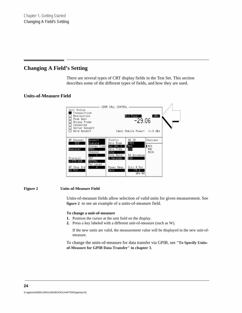
Figure 2 Units-of-Measure Field
Units-of-measure fields allow selection of valid units for given measurement. See figure 2 to see an example of a units-of-measure field.
To change a unit-of-measure1. Position the cursor at the unit field on the display.2. Press a key labeled with a different unit-of-measure (such as W).
If the new units are valid, the measurement value will be displayed in the new unit-of-measure.
To change the units-of-measure for data transfer via GPIB, see "To Specify Units-of-Measure for GPIB Data Transfer" in chapter 3.
24
S:\agilent\e8285\USRGUIDE\BOOK\CHAPTERS\getstart.fb
Chapter 1, Getting StartedChanging A Field’s Setting
Underlined Immediate-Action Field
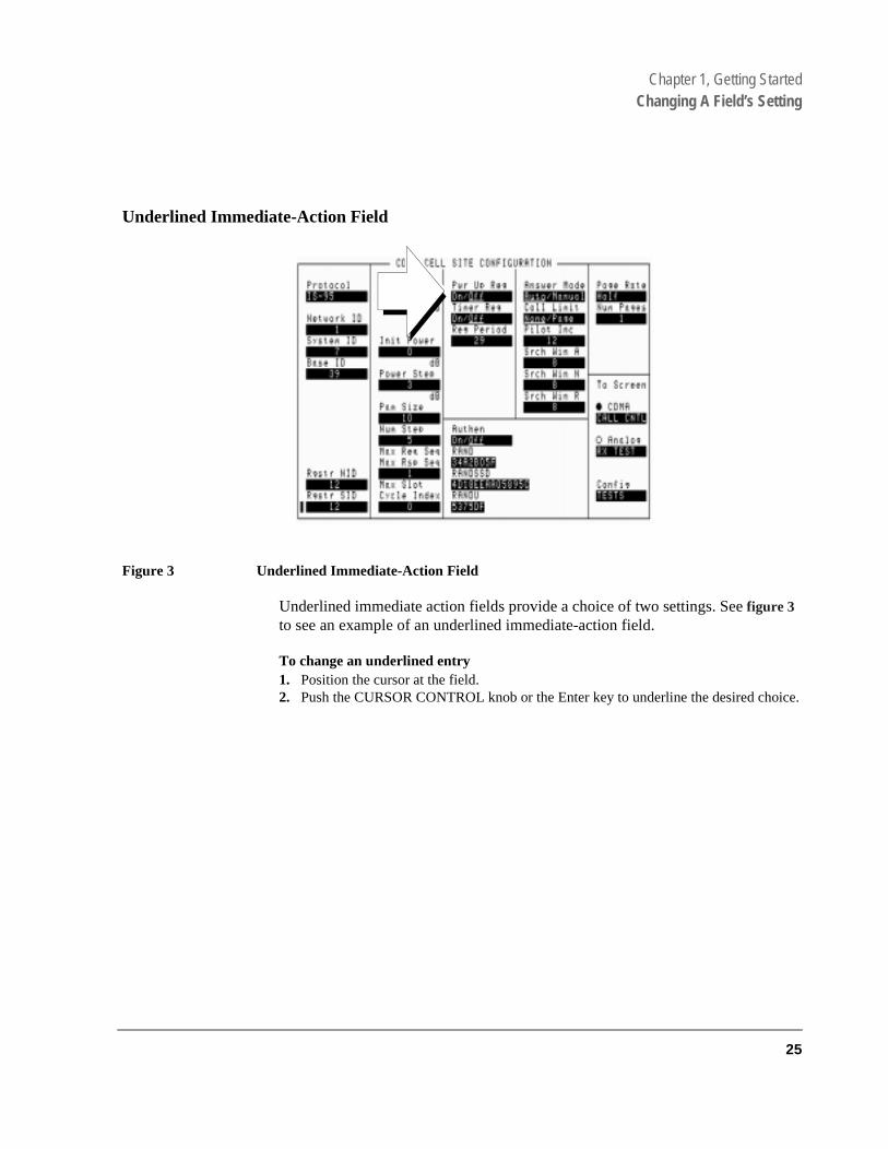
Figure 3 Underlined Immediate-Action Field
Underlined immediate action fields provide a choice of two settings. See figure 3 to see an example of an underlined immediate-action field.
To change an underlined entry1. Position the cursor at the field.2. Push the CURSOR CONTROL knob or the Enter key to underline the desired choice.
25

Chapter 1, Getting StartedChanging A Field’s Setting
One-of-Many Field
Figure 4 One-of-Many Field
One-of-many fields display a list of choices when selected. See figure 4 to see an example of a one-of many field.
To make a one-of-many choice1. Position the cursor at the field.2. Push the Cursor Control knob or the Enter key to display the choices.3. Move the cursor through the choices by turning the knob.4. Push the Cursor Control knob or the Enter key to make the choice.
26
S:\agilent\e8285\USRGUIDE\BOOK\CHAPTERS\getstart.fb

Chapter 1, Getting StartedChanging A Field’s Setting
Numeric-Entry Field
Figure 5 Numeric-Entry Field
Numeric-entry fields contain numeric values. See figure 5 to see an example of a numeric-entry field.
To change a value1. Position the cursor at the field.2. Key in the desired number using the DATA keys.3. Press Enter to select the choice.
OR
4. Position the cursor at the field.5. Push the Cursor Control knob to highlight the desired choice.6. Turn the knob to increment or decrement the value.7. Push the Cursor Control knob or the Enter key to select the choice.
27
Chapter 1, Getting StartedObtaining Measurement Results
sults rming
nt
Obtaining Measurement Results
Setting Up a Call
To obtain CDMA measurements, the Test Set must have the MSUT (Mobile Station Under Test) on a call (the Connected annunciator on the CDMA CALL CONTROL screen is lit when the MSUT is on a call).
The procedure for setting up a call is provided in “Setting Up a Call”, found in the Agilent Technologies E8285A Application Guide. In the Agilent E8285A Application Guide, there are also procedures for performing CDMA tests.
Triggering and Displaying Measurements
When operated over the front panel (local control), Test Set measurement reare obtained by selecting a screen that displays the desired measurement, athe measurement if necessary, and observing the displayed value.
When operated remotely, measurement results are obtained via GPIB by triggering a measurement if necessary and querying the desired measuremefield.
NOTE: In CDMA mode, transmitter (TX) measurements and receiver (RX) measurements can runconcurrently. For example, an Average Power or Channel Power measurement can be queriedwhile the RX TEST screen is selected and an FER measurement is running.
For a detailed description of triggering measurements, see "Measurement Triggering Process" on page 73.
28
S:\agilent\e8285\USRGUIDE\BOOK\CHAPTERS\getstart.fb

Chapter 1, Getting StartedObtaining Measurement Results
rear-
an trol/
ting
ctor,
Preparing the Test Set for GPIB Control
1. If other GPIB devices are in the system, attach an GPIB cable from the Test Set’spanel GPIB connector to any one of the other devices in the test system.
2. Access the I/O CONFIGURE screen and perform the following steps:
a. Set the Test Set’s GPIB address using the GPIB Adrs field (see "Addressing" on page 34).
b. Set the Test Set’s GPIB Controller capability using the Mode field.
• Talk&Listen configures the Test Set to be controlled through GPIB with external controller. The Test Set has Active Controller capability (take conpass control) in this mode.
• Control configures the Test Set to be the system controller. Use this setif the Test Set will be the only controller on the GPIB. Selecting Control automatically makes the Test Set the active controller.
NOTE: Only one active controller is allowed on the GPIB at one time!
3. If an GPIB printer is or will be connected to the Test Set’s rear-panel GPIB conneperform the following steps:
a. Access the PRINTER CONFIGURE screen.
b. Select one of the supported GPIB printer models using the Model field.
c. Set the Printer Port field to GPIB.
d. Set the printer address using the Printer Address field.
29

Chapter 1, Getting StartedObtaining Measurement Results
con-
General Programming Procedure
1. For each measurement you want to perform programmatically, make the measurement manually using the front-panel controls of the Test Set. You will find procedures for making measurements in the Agilent E8285A Application Guide. Record, in sequential order, the screens selected and the settings made within each screen.
2. Record the measurement result(s).
3. Develop the program using the measurement procedure generated in step 2. For CDMA measurements, the Agilent E8285A Application Guide provides step-by-step GPIB command examples.
4. Make sure the desired measurement is selected and in the ON state. This is the PRESET state for most measurements. However, if a previous program has set the state to OFF, no measurement result will be available. Attempting to read from a measurement field that is not in the ON state will cause GPIB Error:-420 QueryUNTERMINATED.
5. Trigger the desired measurement if the RETRigger MODE is SINGle. You will find that the Test Set automatically enters REPetitive trigger MODE for CDMA measure-ments when an GPIB command is sent to it.
6. Send the appropriate MEASure query command to initiate a reading. This will place the measured value into the Test Set’s Output Queue.
7. Use the ENTER statement to transfer the measured value to a variable within thetext of the program.
30
S:\agilent\e8285\USRGUIDE\BOOK\CHAPTERS\getstart.fb
Chapter 1, Getting StartedObtaining Measurement Results
Test
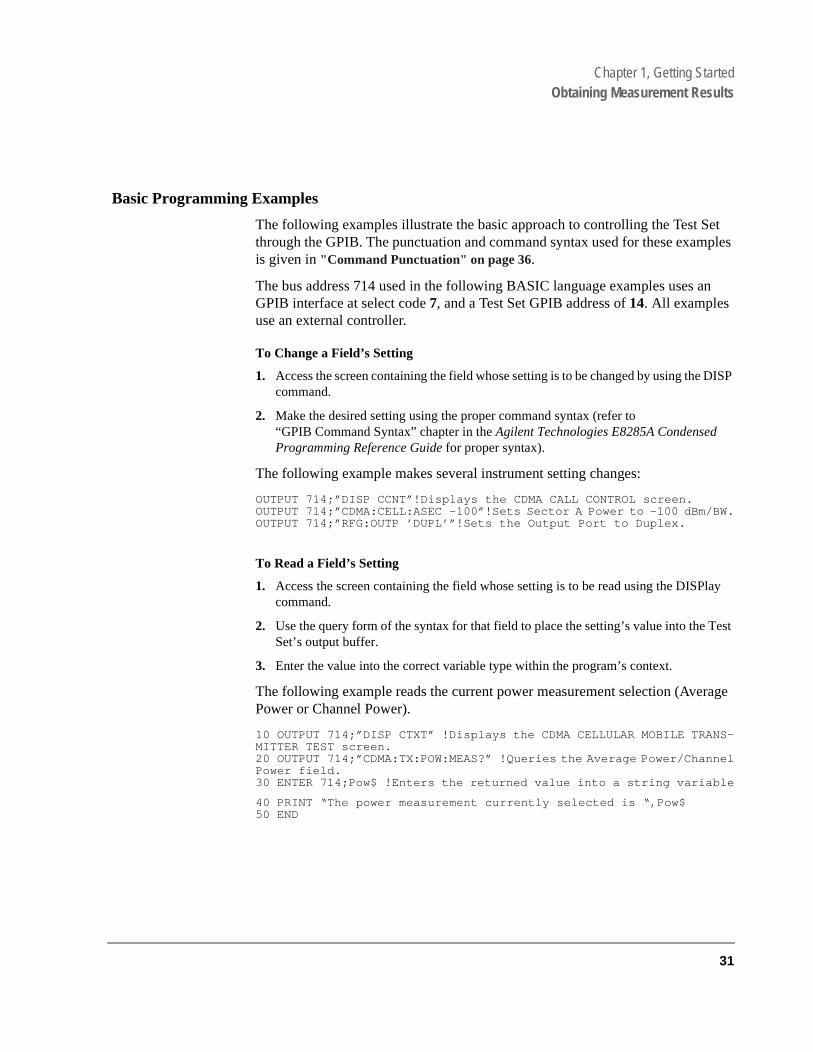
Basic Programming Examples
The following examples illustrate the basic approach to controlling the Test Set through the GPIB. The punctuation and command syntax used for these examples is given in "Command Punctuation" on page 36.
The bus address 714 used in the following BASIC language examples uses an GPIB interface at select code 7, and a Test Set GPIB address of 14. All examples use an external controller.
To Change a Field’s Setting
1. Access the screen containing the field whose setting is to be changed by using the DISP command.
2. Make the desired setting using the proper command syntax (refer to“GPIB Command Syntax” chapter in the Agilent Technologies E8285A Condensed Programming Reference Guide for proper syntax).
The following example makes several instrument setting changes:
OUTPUT 714;”DISP CCNT”!Displays the CDMA CALL CONTROL screen.OUTPUT 714;”CDMA:CELL:ASEC -100”!Sets Sector A Power to -100 dBm/BW.OUTPUT 714;”RFG:OUTP ’DUPL’”!Sets the Output Port to Duplex.
To Read a Field’s Setting
1. Access the screen containing the field whose setting is to be read using the DISPlay command.
2. Use the query form of the syntax for that field to place the setting’s value into the Set’s output buffer.
3. Enter the value into the correct variable type within the program’s context.
The following example reads the current power measurement selection (Average Power or Channel Power).
10 OUTPUT 714;”DISP CTXT” !Displays the CDMA CELLULAR MOBILE TRANS-MITTER TEST screen.20 OUTPUT 714;”CDMA:TX:POW:MEAS?” !Queries the Average Power/ChannelPower field.30 ENTER 714;Pow$ !Enters the returned value into a string variable
40 PRINT “The power measurement currently selected is “,Pow$50 END
31

Chapter 1, Getting StartedObtaining Measurement Results
the
To Make a Simple Measurement
1. Access the screen containing the desired measurement by using the DISP command.
2. Use the MEAS form of the syntax for that measurement to place the measured value into the Test Set’s output buffer.
3. Enter the value into the correct variable type within the program’s context (refer to“Number Measurement Syntax” in GPIB Command Syntax chapter of the Agilent E8285A Condensed Programming Reference Guide for the proper variable type).
NOTE: Whenever a numeric value is queried, the returned value is always in GPIB Units. Refer to"To Specify Units-of-Measure for GPIB Data Transfer" on page 56.
The following example program illustrates how to make settings and then take a reading from the Test Set. This setup takes a reading from the analog spectrum analyzer’s marker after tuning it to the RF generator output frequency.
10 Addr=71420 OUTPUT Addr;”*RST”! Preset to known state25 OUPTUT Addr;”CONF:OFR 0” !Set the RF frequency offset to 0MHz.30 OUTPUT Addr;”TRIG:MODE:RETR SING”! Sets single trigger40 OUTPUT Addr;”DISP RFG”! Selects the RF GENERATOR screen50 OUTPUT Addr;”AFG1:FM:STAT OFF”! Turns FM OFF60 OUTPUT Addr;”RFG:AMPL -66 DBM”! Sets RF Gen amplitude to -66dBm70 OUTPUT Addr;”RFG:FREQ 500 MHZ”! Sets RF Gen frequency to 500MHz80 OUTPUT Addr;”RFG:AMPL:STAT ON”! Turns RF Gen output ON90 OUTPUT Addr;”DISP SAN”! Selects SPECTRUM ANALYZER screen100 OUTPUT Addr;”SAN:CRF 500 MHZ”! Center Frequency 500 MHz110 ! -------------------MEASUREMENT SEQUENCE--------------------120 OUTPUT Addr;”TRIG”! Triggers reading130 OUTPUT Addr;”MEAS:SAN:MARK:LEV?”! Query of Spec Anl markerlevel140 ENTER Addr;Lvl! Places measured value in variable Lvl150 DISP Lvl! Displays value of Lvl160 END
The above example is very simple and is designed to demonstrate the fundamental procedure for obtaining a measurement result. Many other factors must be considered when designing a measurement procedure, such as instrument settings, signal routing, settling time, filtering, triggering and measurement speed.
32
S:\agilent\e8285\USRGUIDE\BOOK\CHAPTERS\getstart.fb

Chapter 1, Getting StartedControl Annunciators
ote
ice
Control Annunciators
The letters and symbols at the top right corner of the display indicate these conditions:
• R indicates the Test Set is in remote mode. The Test Set can be put into the remmode by an external controller or by an IBASIC program running on thebuilt-in IBASIC controller.
• L indicates the Test Set has been addressed to listen.
• T indicates the Test Set has been addressed to talk.
• S indicates the Test Set has sent the require service message by setting the servrequest (SRQ) bus line true. (See "Status Reporting" on page 101).
• C indicates the Test Set is currently the active controller on the bus.
• * indicates an IBASIC program is running.
• ? indicates an IBASIC program is waiting for a user response.
• - indicates an IBASIC program is paused.
33

Chapter 1, Getting StartedAddressing
to
hes when
g the r of
Addressing
Setting the Test Set Bus Address
The Test Set’s GPIB bus address is set using the GPIB Adrs field which is located on the I/O CONFIGURE screen. The Test Set’s GPIB address is set decimal 14 at the factory. To set a different GPIB bus address; select the I/OCONFIGURE screen and position the cursor next to the GPIB Adrs field. The address can be set from decimal 0 to 30 using the numeric DATA keys, or bypushing and then rotating the CURSOR CONTROL knob. There are no switcfor setting the GPIB bus address in the Test Set. The new setting is retained the Test Set is turned off.
Displaying the Bus Address
The Test Set’s GPIB bus address can be displayed by pressing and releasinShift key, then the Local key. The address is displayed in the upper-left cornethe display.
34
S:\agilent\e8285\USRGUIDE\BOOK\CHAPTERS\getstart.fb

Chapter 1, Getting StartedGPIB Command Guidelines
GPIB Command Guidelines
Command Names
GPIB commands are not case sensitive. Upper and lower case characters can be used for all commands.
For example, to set the destination of AF Generator 1 to Audio Out, any of the following command strings are valid:
“AFGENERATOR1:DESTINATION ’AUDIO OUT’” or“afgenerator1:destination ’audio out’” or“afg1:dest ’audio out’” or“AFG1:DEST ’AUDIO OUT’” or“Afg1:Dest ’Audio oUT’”
All command names of more than four characters have an alternate abbreviated form. The abbreviated form is presented in uppercase letters in the syntax diagrams.
35

Chapter 1, Getting StartedGPIB Command Guidelines
Bmingments.
by the
lue in
ld +is e
nd
Command Punctuation
NOTE: Programming Language Considerations: The punctuation rules for the Test Set’s GPIcommands conform to the IEEE 488.2 standard. It is possible that some programlanguages used on external controllers may not accept some of the punctuation requireIt is therefore necessary that the equivalent form of the correct punctuation, as definedlanguage, be used for GPIB operation. Improper punctuation will result in GPIB Error: -102 Syntax Error.
Using Quotes for String Entries
Quotation marks are used to select non-numeric field settings. The value is entered into the command line as a quoted alphanumeric string.
Quotes are used with all underlined (toggling) and one-of-many (menu choice) fields. (See "To Change a Field’s Setting" on page 31.)
For example: to set the RF Generator’s Output Port field to duplex, the menu choice Dupl would be entered into the command string.
“RFG:OUTP ’Dupl’”
Using Spaces
When changing a field’s setting, a space must always precede the setting vathe command string, regardless of the field type.
RFG:FREQ space 850MHZ
RFG:ATT space ’OFF’
Using Colons to Separate Commands
The GPIB command syntax is structured using a control hierarchy that is analogous to manual operation.
The control hierarchy for making a manual instrument setting using the front-panel controls is as follows: first the screen is accessed, then the desired fieselected, then the appropriate setting is made. GPIB commands use the samhierarchy. The colon (:) is used to separate the different levels of the commahierarchy.
For example: To set the AF Analyzer’s input gain to 40 dB, the following command syntax would be used:
“DISP AFAN”“AFAN:INP:GAIN ’40 dB’”
36
S:\agilent\e8285\USRGUIDE\BOOK\CHAPTERS\getstart.fb

Chapter 1, Getting StartedGPIB Command Guidelines
and
d
ext s for ple
Using the Semicolon to Output Multiple Commands
Multiple commands can be output from one program line by separating the commands with a semicolon (;). The semicolon tells the Test Set’s GPIB command parser to back up one level of hierarchy and accept the next commat the same level as the previous command.
For example, on one command line, it is possible to:
1. access the AF ANALYZER screen,
2. set the AF analyzer’s input to AM Demod
3. set Filter 1 to 300 Hz HPF
4. set Filter 2 to 3kHz LPF
“DISP AFAN;AFAN:INP ’AM DEMOD’;FILT1 ’300Hz HPF’;FILT2 ’3kHz LPF’”
The semicolon after the “DISP AFAN” command tells the Test Set’s GPIB command parser that the next command is at the same level in the commanhierarchy as the display command. Similarly, the semicolon after the INP ’AMDEMOD’ command tells the command parser that the next command (FILT1’300Hz HPF’) is at the same command level as the INP ’AM DEMOD’ command.
Using the Semicolon Colon (;:) to Separate Commands
A semicolon followed by a colon (;:) tells the GPIB command parser that the ncommand is at the top level of the command hierarchy. This allows commanddifferent instruments to be output on one command line. The following examsets the RF Analyzer’s tune frequency to 850 MHz, and then sets the AF Analyzer’s input to FM Demod.
“RFAN:FREQ 850 MHZ;:AFAN:INP ’FM DEMOD’”
37

Chapter 1, Getting StartedGPIB Command Guidelines
Using Question Marks to Query Setting or Measurement Fields
The question mark (?) is used to query (read-back) an instrument setting or measurement value. To generate the query form of a command, place the question mark immediately after the command. Queried information must be read into the proper variable type within the program context before it can be displayed, printed, or used as a numeric value in the program.
Queried information is returned in the same format used to set the value (a queried numeric field returns numeric data; quoted string fields return quoted string information).
For example, the following BASIC language program statements query the current setting of the AFGen 1 To field:
OUTPUT 714;”AFG1:DEST?”!Query the AFGen1 To field.ENTER 714;Afg1_to$!Enter queried value into a string variable
38
S:\agilent\e8285\USRGUIDE\BOOK\CHAPTERS\getstart.fb
Chapter 1, Getting StartedGPIB Command Guidelines
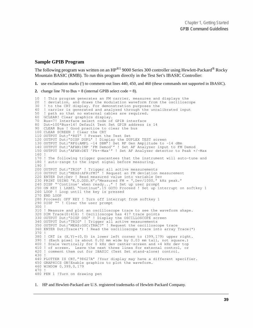
Sample GPIB Program
The following program was written on an HP®1 9000 Series 300 controller using Hewlett-Packard® Rocky Mountain BASIC (RMB). To run this program directly in the Test Set’s IBASIC Controller:
1. use exclamation marks (!) to comment-out lines 440, 450, and 460 (these commands not supported in IBASIC).
2. change line 70 to Bus = 8 (internal GPIB select code = 8).
10 ! This program generates an FM carrier, measures and displays the20 ! deviation, and draws the modulation waveform from the oscilloscope30 ! to the CRT display. For demonstration purposes the40 ! carrier is generated and analyzed through the uncalibrated input50 ! path so that no external cables are required.60 GCLEAR! Clear graphics display.70 Bus=7! Interface select code of GPIB interface80 Dut=100*Bus+14! Default Test Set GPIB address is 1490 CLEAR Bus ! Good practice to clear the bus100 CLEAR SCREEN ! Clear the CRT110 OUTPUT Dut;”*RST” ! Preset the Test Set120 OUTPUT Dut;”DISP DUPL” ! Display the DUPLEX TEST screen130 OUTPUT Dut;”RFG:AMPL -14 DBM”! Set RF Gen Amplitude to -14 dBm140 OUTPUT Dut;”AFAN:INP ’FM Demod’” ! Set AF Analyzer input to FM Demod150 OUTPUT Dut;”AFAN:DET ’Pk+-Max’” ! Set AF Analyzer detector to Peak +/-Max160 !170 ! The following trigger guarantees that the instrument will auto-tune and180 ! auto-range to the input signal before measuring.190 !200 OUTPUT Dut;”TRIG” ! Trigger all active measurements210 OUTPUT Dut;”MEAS:AFR:FM?” ! Request an FM deviation measurement220 ENTER Dut;Dev ! Read measured value into variable Dev230 PRINT USING “K,D.DDD,K”;”Measured FM = “,Dev/1000,” kHz peak.”240 DISP “’Continue’ when ready...” ! Set up user prompt250 ON KEY 1 LABEL “Continue”,15 GOTO Proceed ! Set up interrupt on softkey 1260 LOOP ! Loop until the key is pressed270 END LOOP280 Proceed: OFF KEY ! Turn off interrupt from softkey 1290 DISP “” ! Clear the user prompt300 !310 ! Measure and plot an oscilloscope trace to see the waveform shape.320 DIM Trace(0:416) ! Oscilloscope has 417 trace points330 OUTPUT Dut;”DISP OSC” ! Display the OSCILLOSCOPE screen340 OUTPUT Dut;”TRIG” ! Trigger all active measurements350 OUTPUT Dut;”MEAS:OSC:TRAC?” ! Request the oscilloscope trace360 ENTER Dut;Trace(*) ! Read the oscilloscope trace into array Trace(*)370 !380 ! CRT is (X,Y)=(0,0) in lower left corner to (399,179) upper right.390 ! (Each pixel is about 0.02 mm wide by 0.03 mm tall, not square.)400 ! Scale vertically for 0 kHz dev center-screen and +4 kHz dev top410 ! of screen. Leave the next three lines for external control, or420 ! comment them out for IBASIC (Test Set stand-alone) control.430 !440 PLOTTER IS CRT,”98627A” !Your display may have a different specifier.450 GRAPHICS ON!Enable graphics to plot the waveform.460 WINDOW 0,399,0,179470 !480 PEN 1 !Turn on drawing pen
1. HP and Hewlett-Packard are U.S. registered trademarks of Hewlett-Packard Company.
39

Chapter 1, Getting StartedGPIB Command Guidelines
490 MOVE 0,89.5+Trace(0)/4000*89.5500 FOR I=1 TO 416510 DRAW I/416*399,89.5+Trace(I)/4000*89.5520 NEXT I530 END
40
S:\agilent\e8285\USRGUIDE\BOOK\CHAPTERS\getstart.fb

Chapter 1, Getting StartedVerifying that the Test Set is Operating Properly
e
Verifying that the Test Set is Operating Properly
If your Test Set powers-up and displays the CDMA CALL CONTROL screen, but you suspect an instrument problem, the CDMA Mode Quick Check will verify operation of the instrument’s basic functions.
CDMA Mode Quick Check
NOTE: This procedure assumes that the Test Set is configured for cellular mobile station testing. Ifnecessary, access the CONFIGURE screen and turn PCS Intrfc Control Off. It will then benecessary to cycle power.
1. Remove any cabling from the front-panel connectors.
2. Turn instrument power on (if it is not already on).
3. Press the Preset key.
4. Press and release the Config key to access the CONFIGURE screen.
5. Position the cursor in the RF Display field, and press the knob to select Freq. The RF Offset and (Gen)-(Anl)fields will appear below RF Display.
6. Change the (Gen)-(Anl) value to 0 MHz.
7. Position the cursor in the Output Port field and Select Dupl.
8. Press the Gen control key to access the CDMA GENERATOR CONTROL screen.
9. Enter -50 dBm/BW in the Sctr A Pwr field.
10. Press and release the Shift key then the Gen control key to access the CDMA RE-VERSE CHANNEL SPECTRUM analyzer screen.
11. Position the cursor in the Ref Level field, and press +/-, 1, 0, ENTER to enter a refer-ence level of -10 dBm.
12. Connect the DUPLEX OUT front panel port to the RF IN/OUT port.
13. The display should show a CDMA signal, approximately 1.23 MHz wide.
If no failure is indicated by this test, but you still suspect a problem, refer to thperformance tests information in the Agilent Technologies E8285A Assembly Level Repair Manual.
41

Chapter 1, Getting StartedVerifying that the Test Set is Operating Properly
42
S:\agilent\e8285\USRGUIDE\BOOK\CHAPTERS\getstart.fb

2
Configuring Your Test Set
"To Set RF Voltage Interpretation (50 ohm/emf)" on page 45"To Set the Date and Time" on page 44"To Change the Beeper’s Volume" on page 44
43

Chapter 2, Configuring Your Test SetGeneral Operating Information
General Operating Information
The following configuration information discusses general operating information for some of the fields in the CONFIGURE screen.
To Set the Date and Time
1. Access the CONFIGURE screen.
2. Select the Date field and use the DATA keys to enter the date in the format shown below the field.
3. Select the Time field and use the DATA keys to enter the time in the format shown below the field.
The Test Set has a built-in clock that keeps track of the date and time. It is powered by an internal battery to keep it operating when the instrument is off.
To Change the Beeper’s Volume
1. Access the CONFIGURE screen.
2. Select the Beeper field to display the volume choices.
3. Select the desired choice.
The beeper alerts you to important operating and measurement conditions. It beeps any time a message is displayed at the top of the screen. These messages warn you of conditions such as exceeding the RF input level or trying to set a field to an unacceptable value. Therefore, it is recommended that you do not disable the beeper.
44
S:\agilent\e8285\USRGUIDE\BOOK\CHAPTERS\configts.fb

Chapter 2, Configuring Your Test SetGeneral Operating Information
To Set RF Voltage Interpretation (50 ohm/emf)
1. Access the CONFIGURE screen.
2. Position the cursor in front of the RFGen Volts field.
3. Press the CURSOR CONTROL knob or press the Enter key to select 50 ohm or emf.
Voltage settings can control either:
• the voltage across a 50-ohm load, or
• the open circuit voltage (emf).
This setting affects the RF Generator and Tracking Generator amplitudes.
45

Chapter 2, Configuring Your Test SetGeneral Operating Information
46
S:\agilent\e8285\USRGUIDE\BOOK\CHAPTERS\configts.fb

3
Operating Overview
47

Chapter 3, Operating Overview
• "To Change the Measurement Display" on page 49• "To Enter and Change Values" on page 58• "Saving and Recalling Instrument Setups" on page 61• "Using User Keys" on page 65• "Setting an RF Generator/Analyzer Frequency Offset" on page 68• "Setting RF Generator/Analyzer Level Offsets" on page 69• "Interaction Between Screens" on page 70• "Printing A Screen" on page 72• "Measurement Triggering Process" on page 73• "Triggering Analog Measurements In Local Mode (Front Panel Operation)" on
page 77• "Triggering CDMA Measurements In Local Mode (Front Panel Operation)" on
page 80• "Triggering Analog Measurements In Remote Mode (GPIB Operation)" on page
83• "Triggering CDMA Measurements In Remote Mode (GPIB Operation)" on page
85• "Passing Instrument Control" on page 87
48
S:\agilent\e8285\USRGUIDE\BOOK\CHAPTERS\opoverv.fb

Chapter 3, Operating OverviewTo Change the Measurement Display
ction,
off.
ludes
be
To Change the Measurement Display
Using the On/Off Function
The on/off function is used for the following operations.
• Measurements that are displayed as numbers, or as meters using the METER funcan be turned on and off.
• The data functions REFerence, METer, HLIMit and LLIMit can be turned on and
• Any instrument function that generates a signal can be turned on and off. This incthe CDMA Sector A Power, Sector B Power, and AWGN.
• Trace displays, such as the CDMA Reverse Channel Spectrum Analyzer, cannotturned off.
The front-panel Yes On/Off key is used to turn measurements, instrument functions and data functions on or off.
Front-Panel Example
The following front-panel operation turns Avg Power off.
1. Move the cursor in front of the unit-of-measure for the Avg Power measurement. 2. Press the Yes On/Off key. The Avg Power measurement field displays the word
OFF in place of units
The GPIB STATe command corresponds to the front-panel Yes On/Off key. You can use 1 in place of on, or 0 in place of off.
GPIB Example
The following GPIB command turns off the Avg Power measurement.
“DISP CCNT;MEAS:CDM:AVGP:STAT OFF”
49

Chapter 3, Operating OverviewTo Change the Measurement Display
ld ER,
mall ber
func-nt.
To Use the METER Format
The METER function displays measurements graphically. The METER format is available for most measurements. To determine if the METER format is provided for a measurement, position the cursor in front of the measurement’s units fieand press the knob. If the message “Press ON/OFF, LIMITs, REF, AVG, METor units” is displayed, the METER format is provided.
As a measurement is displayed on the meter, the value is also displayed in sdigits below the meter. You can specify the high and low end points and numof intervals, or you can use the default meter settings.
Front-Panel Example1. Position the cursor in front of the measurement’s unit-of-measure. 2. Press and release the Shift key, then the Increment set key to select the METER
tion. The default number of average samples is displayed below the measureme3. Select On/Off from the Meters: field on the CRT display 4. Repeat steps 1 and 2 then select LoEnd, Hi End, or Intervals to enter each meter
end point and the meter intervals. 5. Repeat steps 1, 2, and 3 to cancel the meter function.
GPIB Example
The following GPIB command turns on the Avg Power measurement’s meter.
“DISP CCNT;MEAS:CDM:AVGP:MET ON”
50
S:\agilent\e8285\USRGUIDE\BOOK\CHAPTERS\opoverv.fb

Chapter 3, Operating OverviewTo Change the Measurement Display
To Set a Measurement Reference
The REF SET function establishes a measurement reference point. This allows you to make a direct comparison between two measurement results, or between a measurement standard and the actual measurement results.
Referenced measurements are displayed as either a ratio (dB) or difference between the measured value and the reference.
Front-Panel Example1. Position the cursor in front of the unit-of-measure for the measurement you want to set
the reference for. 2. Press and release the Shift key, then the INCR ÷10 key to select the REF SET function. 3. Enter the reference value. 4. Ref appears below the measurement value to indicate that a reference has been set. The
measurement field may display a different unit-of-measure, and limit choices for units.
GPIB Example
The following GPIB command also sets a 10 dBm reference for Avg Power measurements.
“DISP CCNT;MEAS:CDM:AVGP:REF 10 DBM”
51

Chapter 3, Operating OverviewTo Change the Measurement Display
the
s re-g
To Use Measurement Averaging
The AVG (average) function allows you to reduce the effects of a rapidly changing measurement by displaying the average value of a number of measurements.
When Averaging is used, the displayed value will ramp (as opposed to step) in response to changes in the measured values.
Pressing the Meas reset key clears the measurement history for all measurements and restarts the averaging process.
Front-Panel Example1. Position the cursor in front of the measurement’s unit-of-measure. 2. Press and release the Shift key, then the INCR × 10 key to select the AVG function. The
default number of average samples is displayed below the measurement.
• Enter the desired number of measurement samples to be used for calculatingaverage, or
• Press the Yes On/Off key to use the currently-displayed number of samples.
3. To turn averaging off, position the cursor in front of the unit-of-measure and preslease the Shift key, then the INCR × 10 key, then the Yes On/Off key to turn averaginoff.
GPIB Example
The following GPIB command averages Avg Power measurements over 10 samples.
“DISP CCNT;MEAS:CDM:AVGP:AVER 10;AVER:STAT ON”
52
S:\agilent\e8285\USRGUIDE\BOOK\CHAPTERS\opoverv.fb

Chapter 3, Operating OverviewTo Change the Measurement Display
its
gs to
also ng
tion.
ned
IM-
ure-
Setting Measurement Limits
The LO LIMIT and HI LIMIT functions are used to define a measurement “window” to alert you to measurements that are outside these limits. When limare assigned, Lo and/or Hi appear by the measurement.
A measurement that goes above or below the defined limits causes three thinhappen:
1. A message appears at the top of the screen indicating a limit was exceeded. 2. The Lo or Hi indicator by the measurement flashes. 3. The Beeper beeps if it is has not been turned off in the CONFIGURATION screen.
Limits are helpful when you can’t watch the Test Set display while you are making an adjustment on the equipment you are testing or repairing. They area convenient way of alerting you to long-term measurement drift without havito observe the screen.
Front-Panel Example1. Position the cursor in front of the unit-of-measure for the measurement you are setting
limits for. 2. Press and release the Shift key, then the down-arrow key to select the LO LIMIT func-
tion. 3. Enter the measurement’s low limit value and unit-of-measure.1
4. Press and release the Shift key, then the up-arrow key to select the LO LIMIT func5. Enter the measurement’s high limit value and unit-of-measure.1
To reset a limit that has been exceeded:
1. Position the cursor in front of the unit-of-measure for the measurement you assigthe limit to.
2. Press and release the Shift key, then the down-arrow (LO LIMIT) or up-arrow (HI LIT key, or press the Meas reset key.
1. The fundamental unit for the LIMITs does not have to be the same as the measment’s units. For instance, when measuring AC Level in Volts, you can set HI and LOLIMITs in units of dBm if desired.
53

Chapter 3, Operating OverviewTo Change the Measurement Display
To remove a limit you have set:
1. Position the cursor in front of the unit-of-measure for the measurement you assigned the limit to.
2. Press and release the Shift key, then the down-arrow (LO LIMIT) or up-arrow (HI LIM-IT key, then press the Yes On/Off key.
GPIB Example
The following GPIB command sets limits for the average power measurement. These limits will indicate if the power level is between −5 dBm and 5 dBm.
“DISP CTXT;MEAS:CDM:AVGP:LLIM -5;LLIM:STAT ON;:MEAS:CDM:AVGP:HLIM5;HLIM:STAT ON”
The Hi limit and Lo limit annunciators will appear below the Avg Power measurement field.
54
S:\agilent\e8285\USRGUIDE\BOOK\CHAPTERS\opoverv.fb

Chapter 3, Operating OverviewTo Change the Measurement Display
t’s
To Specify Units-of-Measure for CRT Display
Most measurements, data functions, and instrument functions allow you to specify which unit-of-measurement should appear on the CRT display.
Front-Panel Example1. Position the cursor in front of the present unit-of-measurement. 2. Press the key labeled with the desired unit.
GPIB Example (DUNits Command)
The following GPIB command causes the Test Set to display Avg Power in units of Watts instead of dBm. The DUNits command will only change the Test Sedisplayed units, not the units used for data transfer through GPIB.
“DISP CCNT;MEAS:CDM:AVGP:DUN W”
Displayed Units DUNits Command MnemonicGHz GHZ MHz MHZ kHz KHZ Hz HZ % ∆ PCTDIFF V V mV MV µV UV dBµV DBUV W W mW MW dBm DBM dBm/BW DBM db DB % PCT s S ms MS
55

Chapter 3, Operating OverviewTo Change the Measurement Display
To Specify Units-of-Measure for GPIB Data Transfer
GPIB Units (UNITs command) are used by the Test Set when sending or receiving numeric values for most field settings and measurement results throughGPIB. Some measurements allow a choice of GPIB Units, but changing GPIB Units has no affect on the Display Units or Attribute Units settings.
Attribute Units (AUNits command) are used by the Test Set when sending or receiving numeric values for data functions (Hi and Lo Limits, Reference, Meter, and Averaging) through GPIB. Some measurements allow a choice of Attribute Units, but changing Attribute Units has no affect on the Display Units or GPIB Units settings.
GPIB Example (UNITs command)
The following command changes the GPIB Units for the Avg Power measurement to W (dBm is the power-up default setting).
“DISP CTXT;MEAS:CDM:AVGP:UNIT W”
GPIB Example (AUNits command)
The following command changes the Attribute Units for the Avg Power measurement to W (dBm is the power-up default setting).
“DISP CTXT;MEAS:CDM:AVGP:AUN W”
After receiving this command, the Test Set will use units of Watts for data functions (such as High and Low Limits).
56
S:\agilent\e8285\USRGUIDE\BOOK\CHAPTERS\opoverv.fb

Chapter 3, Operating OverviewTo Change the Measurement Display
Table 2 Functions with GPIB and Attribute Units That Can Be Changed
Function Available
GPIB Units Applies to UNITs
CommandApplies to AUNits
Command
TX Power measurement W or DBM x x
Average Power measurement W or DBM x x
Channel Power measurement W or DBM x x
Adjacent Channel Power:
Lower Ratio, Upper Ratio
Lower Level, Upper Level
x x
DB or PCT x x
W or DBM x x
SINAD measurement DB or PCT x x
Distortion measurement DB or PCT x x
SNR measurement DB or PCT x x
RF Generator Amplitude W or DBM x
Frequency Error Hz x x
57
Chapter 3, Operating OverviewTo Enter and Change Values
use
t val-
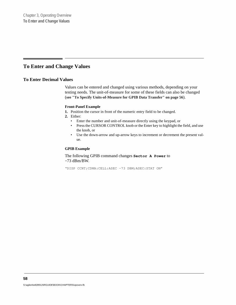
To Enter and Change Values
To Enter Decimal Values
Values can be entered and changed using various methods, depending on your testing needs. The unit-of-measure for some of these fields can also be changed (see "To Specify Units-of-Measure for GPIB Data Transfer" on page 56).
Front-Panel Example1. Position the cursor in front of the numeric entry field to be changed. 2. Either:
• Enter the number and unit-of-measure directly using the keypad, or• Press the CURSOR CONTROL knob or the Enter key to highlight the field, and
the knob, or• Use the down-arrow and up-arrow keys to increment or decrement the presen
ue.
GPIB Example
The following GPIB command changes Sector A Power to −73 dBm/BW.
“DISP CCNT;CDMA:CELL:ASEC -73 DBM;ASEC:STAT ON”
58
S:\agilent\e8285\USRGUIDE\BOOK\CHAPTERS\opoverv.fb

Chapter 3, Operating OverviewTo Enter and Change Values
To Enter Hexadecimal Values
Hexadecimal (Hex) values are used for entering some signaling parameters, such as MIN (Mobile Identification Number). No unit-of-measure is associated with these values.
Hexadecimal values are either entered from the keypad (using the A-F shifted functions), or by using the Choices menu.
Front-Panel Example
The following front-panel operation enters the Hexadecimal number #H0D2565F15 into the MIN field.
1. Move the cursor to the field below MS ID. 2. If the field currently says Phone Num press the Enter key, use the CURSOR CON-
TROL knob to select MIN, and press the Enter key again. (If MIN is already selected, proceed to step 3.)
3. Use the CURSOR CONTROL knob to select the numeric entry field below MIN.4. Enter 0, then press and release the Shift key, then the 3 key (to select D), enter 2565,
press and release the Shift key, then the 5 key (to select F), enter 15, and then press the Enter key. This is the hexadecimal code derived from the phone number 321-456-7890.
GPIB Example
The following GPIB command also enters the Hexadecimal number 0D2565F15 into the MIN field.
“DISP CCNT;CDMA:MOB:MIN ‘0D2565F15’”
59

Chapter 3, Operating OverviewTo Enter and Change Values
To Enter Values With Exponents
Front-Panel Example
The following front-panel operation changes Confidence (limit) to 95.
1. Press the Call control key. 2. Move the cursor in front of the Confidence field. 3. Enter 9 EEX 1.
The EEX key can be used to enter values in exponential notation. Exponential notation is only allowed on floating-point entry fields.
To Increment/Decrement Values
Incrementing and decrementing values on the Test Set can be performed from the front panel with the CURSOR CONTROL knob or the up/down arrow keys., or the INCR ÷10 and INCR ×10 keys.
The INCR ÷10, INCR ×10, and INCR SET keys are used to assign a specific increment value. To change an increment/decrement setting:
Front-Panel Example1. Move the cursor to the numeric entry field to be changed. 2. To change the current increment/decrement setting by a factor of 10, use the INCR ÷10
or INCR ×10 keys. 3. To set a specific increment/decrement value, press INCR SET, and enter the desired
value.
GPIB Example
The following GPIB command also sets the increment value on the Sector A Power field to 3 dBm/BW, and increments the present value up by 3 dBm/BW.
“DISP CCNT;CDMA:CELL:ASEC:INCR 3;INCR UP”
60
S:\agilent\e8285\USRGUIDE\BOOK\CHAPTERS\opoverv.fb

Chapter 3, Operating OverviewSaving and Recalling Instrument Setups
Saving and Recalling Instrument Setups
The save and recall functions allow you to store different instrument setups and retrieve them later, eliminating the task of re-configuring the Test Set.
The number of available save registers depends on how many changes were made to the BASE instrument setup for each save. (See "Specifying BASE Settings" on page 64.) The smaller the number of changes, the greater the number of SAVE registers that can be used (typically over 200).
SAVE/RECALL register settings can be saved to several types of mass storage. This allows you to “back up” the settings in case you need to clear them frommemory (see "Memory Considerations" on page 64) for running large programs, orwhen a firmware upgrade is performed.
To Save an Instrument Setup 1. Press and release the Shift key, then the Previous key to access the I/O CONFIGURE
screen. Select the storage media using the Save/Recall field. (The default storage media is internal memory.)
2. Make any changes to the instrument that you want to save in a register. 3. Press and release the Shift key, then the Recall key to select the SAVE function. 4. Use the Data keys or the Save: menu at the bottom right of the screen to enter the save
register name.
Front-Panel Example
This example saves the current instrument settings.
1. Press and release the Shift key, then the Recall key to select the SAVE function. A prompt appears at the top of the screen asking you to enter a name.
2. Using the Data keys, enter 123, then press the Enter key to assign a name.
GPIB Example
The following GPIB command also SAVES the current instrument settings.
“REG:SAVE 123”
61

Chapter 3, Operating OverviewSaving and Recalling Instrument Setups
To Recall an Instrument Setup 1. Press and release the Shift key, then the Previous key to access the I/O CONFIGURE
screen and select the media to recall settings from using the Save/Recall field. (The default is internal memory.)
2. Press the Recall key. 3. Use the knob to select the desired setup to be recalled from the Recall menu at the
bottom right of the screen.
Front-Panel Example
This example recalls the current instrument settings.
Press RECALL, 1, 2, 3, ENTER. The saved instrument settings are recalled.
GPIB Example
The following GPIB command also recalls register 123.
“REG:REC 123”
To Clear All SAVE Registers
1. Press the Recall key.
2. Use the knob to position the cursor in front of the entry in the Recall menu at the bottom right of the screen.
3. Press the knob or the Enter key. A prompt appears at the top of the screen to verify that you want to clear all registers.
4. Press the Yes On/Off key to select YES.
GPIB Example
The following GPIB command clears all registers
“REG:CLE:ALL”
62
S:\agilent\e8285\USRGUIDE\BOOK\CHAPTERS\opoverv.fb

Chapter 3, Operating OverviewSaving and Recalling Instrument Setups
E.
re Test ings
To Remove (Clear) an Individual SAVE Register 1. Specify where the register is stored using the Save/Recall field on the I/O CON-
FIGURE screen. 2. Press the Recall key.3. Use the knob to position the cursor in front of the register to be removed from the Re-
call menu at the bottom right of the screen. The register name and percentage of SAVE memory occupied by that register are indicated at the very top of the screen.
4. Press the Yes On/Off key. A prompt appears, asking if you want to delete the save reg-ister.
5. Press the Yes On/Off key to select YES. (Press the RATIO W key to select NO.)
GPIB Example
The following GPIB command clears a register
“REG:CLE ‘<quoted string>’”
Choosing Register Names
You can use any number, letter, or combination of numbers and letters as a name for storing instrument settings. For instance; if you want to save a setup for testing a “Vulcan7” radio, you can save the setting as “VULCAN7”.
Two register names are reserved for special purposes: POWERON and BAS
Specifying POWERON Settings
You can specify the instrument setting at power-on by following the procedudescribed in "To Save an Instrument Setup" on page 61, and choosing the registername POWERON. If a SAVE Register named POWERON is detected by theSet during its power-on routine, the Test Set will configure itself using the settstored in the POWERON register.
NOTE: If the Test Set does not successfully complete its power-on routine because of the POWERONsettings (e.g., the Test Set displays a message that requires you to cycle power to recover) youmust:
1. Turn off the Test Set. 2. Hold down the PRESET and the Hz/uV keys simultaneously.3. Turn on power while holding the PRESET and the Hz/uV keys down until the CALL
CONTROL screen appears.
This procedure will clear all SAVE registers, including POWERON.
63

Chapter 3, Operating OverviewSaving and Recalling Instrument Setups
ust
Specifying BASE Settings
The BASE register contains any field settings the user has SAVEd that are different from the instrument PRESET state. It establishes a reference point for all future SAVEs. (The PRESET state is stored in the BASE register until you SAVE another instrument setup.)
When you SAVE an instrument setup, the new setup is compared to the BASE settings, and any differences are stored under the register name you supply. Because only differences are stored, a much larger number of instrument setups can be saved than if the contents of every field was saved.
When you RECALL an instrument setting, every field is reset to the BASE settings. The SAVED settings are then used to re-establish the desired instrument setup.
You can define your own BASE setting. If your desired settings are very different from the PRESET values, you may want to change the BASE register. This will decrease the amount of memory used to SAVE each setup, and allow you to SAVE many more setups.
CAUTION: Since each SAVE/RECALL register only contains the differences between the setup beingsaved and the present BASE register settings, changing the BASE results in all other savedsetups being ERASED from memory (including the POWERON setting if one has beensaved).
Unless you consistently change the same fields to the same value each time youuse the instrument, you should probably not create your own BASE settings.
Memory Considerations
When the Save/Recall field of the I/O CONFIGURE screen is set to Internal, instrument setups are saved to the same non-volatile RAM used to create RAM Disk(s) and run IBASIC programs. By saving a large number of instrument setups, you reduce the amount of RAM available to run programs. If you get a “memory overflow” message while trying to load a program, you mclear one or more SAVE/RECALL registers to free RAM space).
64
S:\agilent\e8285\USRGUIDE\BOOK\CHAPTERS\opoverv.fb

Chapter 3, Operating OverviewUsing User Keys
; sly
Using User Keys
User keys instantly access instrument settings without using the knob. You can use USER keys to move quickly between fields on the same screen, and to access field settings that are not normally available on the screen you are using.
Local USER keys are used to move between settings on the screen that is displayed. When the USER key is pressed, the cursor instantly moves to, and selects, the assigned field; eliminating the need to turn and push the knob. Five local USER keys are available for each screen: K1, K2, K3, K4, and K5.
Global USER keys are used to access settings that are not available on the current screen. Three global USER keys are available: K1’, K2’, and K3’. (These areshifted functions of the local USER keys.)
When defining USER keys, the ASSIGN function is used to create key definitionsthe RELEASE function removes the definitions. Re-assigning a USER key to adifferent field setting automatically Releases it from the setting it was previouassociated with.
65

Chapter 3, Operating OverviewUsing User Keys
To Assign Local USER Keys
1. Move the cursor to the field you want to assign a local USER key to.
2. Press and release the Shift key, then the K4 key to select the ASSIGN function. Press a local USER key (K1-K5). The USER key number appears in front of the field you as-signed it to.
Example of Assigning a Local USER Key
Use this example to assign local USER key K1 to the Filter 1 field in the RX TEST screen.
1. Access the RX Test screen and position the cursor in front of the Filter 1 field.
2. Press and release the Shift key, then the K4 key to select the ASSIGN function.
3. Press K1. A small 1 appears next to the field indicating that USER key K1 has been assigned to it.
4. Move the cursor to any other field on the screen and press K1. The cursor immediately returns to the Filter 1 field. The field is also highlighted to change the entry using the CURSOR CONTROL knob or arrow keys.
To Release Local USER Keys
1. Display the screen containing the USER key assignment to be removed.
2. Press and release the Shift key, then the K5 key to select the RELEASE function.
3. Press the USER key (K1-K5) that you want to release.
66
S:\agilent\e8285\USRGUIDE\BOOK\CHAPTERS\opoverv.fb
Chapter 3, Operating OverviewUsing User Keys
ber ap-
To Assign Global USER Keys
1. Move the cursor to the field you want to assign a global USER key to.
2. Press and release the Shift key, then the k4 key to select the ASSIGN function.
3. Press a global USER key (K1’ -K3’). Unlike a local USER key, the USER key numdoes not appear in front of the field you assigned a global USER key to. A promptpears at the top of the screen confirming the key assignment.
Example of Assigning a Global USER Key
Use this example to assign global USER key K1’ to the AF Anl In field, and then access this field in the OSCILLOSCOPE screen.
1. Access the AF ANALYZER screen and position the cursor in front of the AF Anl In field.
2. Press and release the Shift key, then the K4 key to select the ASSIGN function.
3. Press and release the Shift key, then the K1’ key. Notice the prompt Global USER key 1 assigned. at the top of the screen.
4. Access the OSCILLOSCOPE screen.
5. Press Shift, K1’.
AF Anl Input, FM Demod is displayed at the top of the screen (assuming the present input is set to FM Demod). To change the input, use the arrow keys, or press the Enter key to access the Choices menu.
A field that is accessed using a global USER key is only displayed at the top of the screen while it is being accessed. Moving the cursor to any other field in the screen causes the USER key field to disappear until it is accessed again.
To Release Global USER Keys
1. Move the cursor to the field with the global USER key assigned to it.
2. Press Shift, K5, Shift, and the USER key to be released (K1’-K3’).
67

Chapter 3, Operating OverviewSetting an RF Generator/Analyzer Frequency Offset
Setting an RF Generator/Analyzer Frequency Offset
You can set a fixed frequency offset between the RF Generator and the RF Analyzer. At power-up and instrument preset this feature is ON with a transmit/receive frequency offset of 45 MHz.
To Turn Off RF Frequency Offset
1. Access the CONFIGURE screen.
2. Position the cursor below the RF Display field and select Freq.
3. Set the RF Offset to Off.
GPIB Example
“CONF:OMOD ‘OFF’”
turns the RF frequency offset off
To Change the RF Frequency Offset
1. Access the CONFIGURE screen.
2. Position the cursor below the RF Display field and select Freq.
3. Set the RF Offset to On.
4. Enter an offset frequency ((Gen)-(Anl)).
68
S:\agilent\e8285\USRGUIDE\BOOK\CHAPTERS\opoverv.fb

Chapter 3, Operating OverviewSetting RF Generator/Analyzer Level Offsets
st
Setting RF Generator/Analyzer Level Offsets
The Test Set relies on level offsets to correctly set up the input signal path attenuators. The user must enter path loss figures on the forward and reverse channel paths independently by accessing the CONFIGURE screen. The Output Port and Input Port fields select which port is being used on the front panel, and the RF Level Offset field turns the level offset on.
At power-up and instrument preset this feature is OFF with 0.0 dB loss entered for all connector fields.
Refer to “Determining and Correcting for RF Path Loss” in Calibrating the TeSet chapter of the Agilent E8285A Application Guide for detailed procedures.
69

Chapter 3, Operating OverviewInteraction Between Screens
Interaction Between Screens
Most fields operate globally; changing the setting in any screen automatically changes that setting in all screens where it is available. AFGen1 Freq is an example of this field type.
Figure 6 Example of How Global Fields Work
Priority fields give the RX TEST and TX TEST screens priority control of their settings. No matter what these fields were set to in other screens, if the RX TEST or TX TEST screen is accessed, the field changes to whatever it was last set to in these screens. The RF Generator Amplitude is an example of this field type. These fields and their preset values are listed in table 3 on page 71.
1.250
AFGen1 Freq
kHz
1.250
AFGen1 Freq
kHz
1.250
AFGen1 Freq
kHz
1.250
AFGen1 Freq
kHz
1.000
AFGen1 Freq
kHz
1.000
AFGen1 Freq
kHz. 21 5 0
RX TEST
RF GENERATOR
TX TEST
DUPLEX
DATA Keys
70
S:\agilent\e8285\USRGUIDE\BOOK\CHAPTERS\opoverv.fb

Chapter 3, Operating OverviewInteraction Between Screens
Using your Test Set, duplicate the steps in figure 7 to demonstrate how the priority fields operate.
Figure 7 Example of How Priority Fields Work
Table 3 Priority RX TEST and TX TEST Fields
Priority Field RX TEST TX TEST
RF Gen Amplitude Presets to −80 dBm (changeable) Always Off
AFGen1 To Presets to FM (changeable) Always Audio Out
AF Anl In Always Audio In Presets to FM Demod (changeable)
Detector Always RMS Presets to Pk +− Max(changeable)
De-emphasis Always Off Presets to 750µs (changeable)
AF Anl Measurement Presets to SINAD (changeable) Presets to Audio Freq (changeable)
-50
Amplitude
dBm
-50
Amplitude
dBm
-50
Amplitude
dBm
- 7 5
1. Access the RX TEST screen and set the Amplitude to -50 dBm.
-50
Amplitude
dBm
-75
Amplitude
dBm
2. Access the RF GENERATOR screen and set the Amplitude to -75 dBm.
3. Access the RX TEST screen. Notice that the Amplitude changes back to -50 dBm.
2. Return to the RF GENERATOR screen. The Amplitude is no longer where you set it in step 2 (-75 dBm).
Since the RX TEST screen has priority control over this field, the RF GENERATOR screen’s Amplitude setting changed when RX TEST was accessed.
71
Chapter 3, Operating OverviewPrinting A Screen
Printing A Screen
To Print A Screen’s Contents
1. Connect a printer to the appropriate rear-panel connector.
2. Press and release the Shift key, then the Print key to access the PRINT CONFIGURE screen and set the Printer Port field to the appropriate type of printer connection.
• If GPIB is selected, enter the GPIB Printer Address of the printer.
3. Select the type of printer you are using in the Model field. If your printer is not listed, configure your printer to emulate one that is listed.
4. Enter a Print Title using the knob (optional). The title will appear at the top ofyour printout.
5. Display the screen you want to print and press the Print key.
To interrupt printing, select the Abort Print field on the PRINT CONFIGURE screen.
72
S:\agilent\e8285\USRGUIDE\BOOK\CHAPTERS\opoverv.fb

Chapter 3, Operating OverviewMeasurement Triggering Process
en.
Measurement Triggering Process
Active Measurements
Only active measurements can be triggered and then queried for a measurement result. Within the Test Set, measurements are differentiated between those that are "active" and those that are "not active". The definition of an active measurement is different for analog measurements than for CDMA measurements.
Definition of Active CDMA Measurement
All CDMA measurements are "active" if:
• either of the following screens is displayed on the CRT of the Test Set
CDMA CELLULAR MOBILE RECEIVER TESTCDMA CELLULAR MOBILE TRANSMITTER TEST
AND
• the measurement is in the ON state
NOTE: Only the Avg/Chan Power measurement is active on the CDMA CALL CONTROL scre
Definition of Active Analog Measurement
An analog measurement is "active" if:
• the field used to display the measurement result is located on the screen which is currently displayed on the CRT of the Test Set
AND
• the measurement is in the ON state
73

Chapter 3, Operating OverviewMeasurement Triggering Process
Triggering A Measurement Cycle
The Test Set starts a measurement cycle when a valid trigger is received. The measurement cycle is the process used by the Test Set to obtain measurement results.
The measurement cycle is a firmware process which, for all active measurements, obtains raw data from the hardware and then processes/formats the raw data into a measurement result. The result is then displayed on the screen, and - if operating in remote mode - sent to the GPIB bus.
The measurement cycle completes when a valid measurement result is obtained for all active measurements.
Trigger Modes
The trigger mode used to start the measurement cycle can be selected by the user. The trigger mode is defined by two parameters: retriggering and settling.
Retriggering
Retriggering refers to what the measurement cycle does once it has completed (obtained a valid measurement result for all active measurements). There are two options:
1. Single retriggering causes the measurement cycle to stop once a valid measurement re-sult has been obtained for all active measurements. A valid trigger must be received to start the measurement cycle again. When a measurement cycle is completed, the values for all active measurements are held until another trigger is received.
2. Repetitive retriggering causes the measurement cycle to automatically start over once a valid measurement result has been obtained for all active measurements. No trigger must be received to start the measurement cycle again. Repetitive retriggering will cause measurements that rely on external signals or hardware generated events (such as Traffic Rho) to be automatically re-armed upon completion of a measurement cycle.
NOTE: The Cont selection in the Meas Cntl field is equal to repetitive retriggering.
74
S:\agilent\e8285\USRGUIDE\BOOK\CHAPTERS\opoverv.fb

Chapter 3, Operating OverviewMeasurement Triggering Process
Settling
Settling refers to the amount of time delay introduced into the measurement cycle to allow signal transients to propagate through the analysis chain and settle out. There are two options:
1. Full settling introduces the appropriate delay for all signal transients which might have occurred at the front panel coincident with the trigger command, to pass through the analysis chain and settle out. Delays are also inserted to allow for internal hardware transients to settle.
2. Fast settling introduces no delay for internal or external signal transients to settle.
There will still be delays introduced by the couplings between autotuning and autor-anging. If the operator wishes to remove these delays as well, all autoranging and autotuning functions must be turned OFF and the operator must explicitly set the rang-ing amplifiers and the frequency tuning. Delays introduced by the measurement pro-cesses themselves cannot be eliminated.
NOTE: CDMA measurements are not affected by the trigger mode settling parameter. CDMAmeasurements are made with a digital signal processor (DSP) which does not require thesettling times associated with analog hardware circuitry.
Rho Suite of Measurements
The following group of CDMA measurements is referred to as the "Rho Suite of Measurements" because a result for each of the following measurements is available each time the Rho Suite of measurements is triggered:
Traffic Rho or TM Rho (only one can be selected)Frequency ErrorAmplitude ErrorTime OffsetPhase ErrorCarrier Feedthrough
75

Chapter 3, Operating OverviewMeasurement Triggering Process
both
nt of
e
igger
nt of
Default Trigger Modes
Default Trigger Mode for Remote Operation: CDMA and Analog Measurements
Upon powerup, or upon receiving a *RST command, or upon pressing the front panel Preset key, the Test Set’s default trigger mode for remote operation of CDMA and analog measurements is Repetitive retriggering with Full settling.
If a local-to-remote transition occurs, the trigger mode will be set to the last trigger mode command received while in remote mode. If no trigger mode command has been received since powerup, the default state is set.
Default Trigger Mode for Local Operation: CDMA Measurements
Upon powerup, or upon receiving a *RST command, or upon pressing the fropanel Preset key, the Test Set’s default trigger mode for front panel operationthe FER and Rho Suite of Measurements is Single retriggering.
If a remote-to-local transition occurs, the trigger mode will be determined by:
• FER - the state of the Meas Cntl field on the CDMA CELLULAR MOBILE RECEIVER TEST screen
• Rho Suite of Measurements - the state of the Meas Cntl field on the CDMA CELLULAR MOBILE TRANSMITTER TEST screen
NOTE: Setting the Meas Cntl field to Cont (Continuous) sets the trigger mode to repetitivretriggering.
Upon powerup, or upon receiving a *RST command, or upon pressing the front panel Preset key, or upon a remote-to-local transition the Test Set’s default trmode for front panel operation of the Avg/Chan Power measurement is Repetitive retriggering.
Default Trigger Mode for Local Operation: Analog Measurements
Upon powerup, or upon receiving a *RST command, or upon pressing the fropanel Preset key, the Test Set’s default trigger mode for front panel operationanalog measurements is Repetitive retriggering with Full settling.
76
S:\agilent\e8285\USRGUIDE\BOOK\CHAPTERS\opoverv.fb

Chapter 3, Operating OverviewTriggering Analog Measurements In Local Mode (Front Panel Operation)
-
ycle.
Triggering Analog Measurements In Local Mode (Front Panel Operation)
1. Select the desired trigger mode.
For Signaling Decoder
• Continuous - Once a measurement has completed, the Test Set is internally retriggered and another measurement cycle begins.
• Single - Requires selection of the Arm Meas field to be begin a measurement c
Manual Operation:
1. Position the cursor at the Single/Cont field.
2. Press the knob to underline the desired mode.
77

Chapter 3, Operating OverviewTriggering Analog Measurements In Local Mode (Front Panel Operation)
or an be auses
he .
For Analog Measurements (other than Signaling Decoder)
• Repetitive retriggering is the only trigger mode available from the front panel fanalog measurements (other than the Signaling Decoder). Single trigger mode csimulated using the Test Set’s measurement hold feature. Selecting the Hold key call currently displayed measurement results to be held on the screen and stops tmeasurement cycle. To resume making measurements press the Hold key again
Recall
Local
Measreset
Preset
Hold
Address
Save
Manual Operation:
1. Press then release the Shift key, then press the Meas reset key to HOLD measurement results.
2. Select HOLD again to return to Repetitive mode.
Meas Reset begins a measurement cycle, interrupting any measurement in progress.
78
S:\agilent\e8285\USRGUIDE\BOOK\CHAPTERS\opoverv.fb

Chapter 3, Operating OverviewTriggering Analog Measurements In Local Mode (Front Panel Operation)
2. Trigger the Signaling Decoder (applies if trigger mode is "Single")
Manual Operation:
1. Position the cursor at the Arm Meas field.
2. Press the knob.
Arming the Signaling Decoder as shown in this example will cause the measurement to be automati-cally triggered by an internal trigger command.
Selecting the Stop Meas field will stop the currently executing measurement cycle for the Signaling Decoder.
79

Chapter 3, Operating OverviewTriggering CDMA Measurements In Local Mode (Front Panel Operation)
-
Triggering CDMA Measurements In Local Mode (Front Panel Operation)
1. Select the desired trigger mode.
For FER and Rho Suite of Measurements
• Continuous - Once a measurement has completed, the Test Set is internally retriggered and another measurement cycle begins.
• Single - Requires selection of the Arm field to be begin a measurement cycle.
Manual Operation:
1. Position the cursor at the Single/Cont field.
2. Press the knob to underline the desired mode.
When Single is selected, the Arm and Disarm fields are displayed. When Continuous is selected the Arm and Disarm fields will not appear.
80
S:\agilent\e8285\USRGUIDE\BOOK\CHAPTERS\opoverv.fb
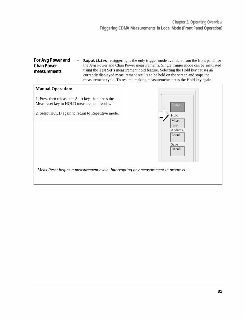
Chapter 3, Operating OverviewTriggering CDMA Measurements In Local Mode (Front Panel Operation)
or ulated
.
For Avg Power and Chan Power measurements
• Repetitive retriggering is the only trigger mode available from the front panel fthe Avg Power and Chan Power measurements. Single trigger mode can be simusing the Test Set’s measurement hold feature. Selecting the Hold key causes all currently displayed measurement results to be held on the screen and stops the measurement cycle. To resume making measurements press the Hold key again
Manual Operation:
1. Press then release the Shift key, then press the Meas reset key to HOLD measurement results.
2. Select HOLD again to return to Repetitive mode.
Meas Reset begins a measurement cycle, interrupting any measurement in progress.
Recall
Local
Measreset
Preset
Hold
Address
Save
81
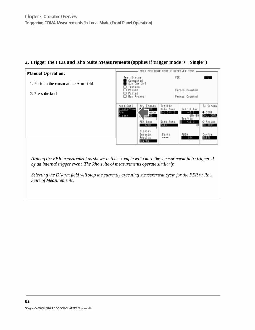
Chapter 3, Operating OverviewTriggering CDMA Measurements In Local Mode (Front Panel Operation)
2. Trigger the FER and Rho Suite Measurements (applies if trigger mode is "Single")
Manual Operation:
1. Position the cursor at the Arm field.
2. Press the knob.
Arming the FER measurement as shown in this example will cause the measurement to be triggered by an internal trigger event. The Rho suite of measurements operate similarly.
Selecting the Disarm field will stop the currently executing measurement cycle for the FER or Rho Suite of Measurements.
82
S:\agilent\e8285\USRGUIDE\BOOK\CHAPTERS\opoverv.fb

Chapter 3, Operating OverviewTriggering Analog Measurements In Remote Mode (GPIB Operation)
the
ea-s Traf-n be
ter-
x-
om-
tor-xplic-the
Triggering Analog Measurements In Remote Mode (GPIB Operation)
1. Select the desired trigger mode.
• Retriggering
• Repetitive - Once a measurement cycle has completed the Test Set is automat-ically re-triggered and another measurement cycle begins.
When the trigger mode is set to repetitive retriggering, consecutive queries ofsame measurement return new measured values.
• Single - Once a measurement cycle has completed the Test Set requires anGPIB trigger command be received to begin a new measurement cycle.
When the trigger mode is set to single retriggering, consecutive queries of thesame measurement (with no intervening trigger) will return the same value. Msurements that rely on external signals or hardware-generated events (such afic Rho) must be re-armed with a new trigger before another measurement camade.
• Settling
• Full - Appropriate time delays introduced into measurement cycle to allow innal or external signal transients to settle.
• Fast - No time delay introduced into measurement cycle to allow internal or eternal signal transients to settle.
The programmer must account for transient settling before issuing a trigger cmand.
There will still be delays introduced by the couplings between autotuning andautoranging. If the programmer wishes to remove these delays as well, all auanging and autotuning functions must be turned OFF and the program must eitly set the ranging amplifiers and the frequency tuning. Delays introduced by measurement processes themselves cannot be eliminated.
GPIB Syntax|"TRIG:MODE:RETR REP" !selects Repetitive retriggering mode.
"TRIG:MODE:RETR SING" !selects Single retriggering mode.
TRIG:MODE:SETT FULL" !selects Full settling mode.
"TRIG:MODE:SETT FAST" !selects Fast settling mode.
83

Chapter 3, Operating OverviewTriggering Analog Measurements In Remote Mode (GPIB Operation)
hake ment
the 647
2. Trigger all active analog measurements (applies if trigger mode is "Single")
GPIB Syntax"TRIG" !triggers all active analog measurements.
GPIB Example Program10 OUTPUT 714;"DISP RFAN"20 OUTPUT 714;"TRIG:MODE:RETR SING;SETT FULL"30 OUTPUT 714;"TRIG"40 END
GPIB Example Program Comments By Line10 !Selects RF Analyzer screen20 !Sets the Test Set’s remote trigger mode to Single retriggering and Full settling30 !Triggers all active analog measurements
Preventing GPIB Bus Lockup
GPIB bus lockup is a condition where the GPIB bus and the Active Controller handsare in a temporary holdoff state while the Active Controller waits to read the measureresult from the Test Set.
This Test Set has a feature that allows the bus to be released automatically when a measurement cycle is unsuccessful. It is called Indefinite Measurement and is automatically ON when the Test Set is powered on and causes the Test Set to sendnumber +1.7976931348623157 e+308 for real number measurements, and 2147483for integer number measurements.
84
S:\agilent\e8285\USRGUIDE\BOOK\CHAPTERS\opoverv.fb

Chapter 3, Operating OverviewTriggering CDMA Measurements In Remote Mode (GPIB Operation)
the
t is putmentsssages
GPIB
ea-s Traf-n be
DMAire the
Triggering CDMA Measurements In Remote Mode (GPIB Operation)
1. Select the desired trigger mode.
• Retriggering
• Repetitive - Once a measurement cycle has completed the Test Set is automat-ically re-triggered and another measurement cycle begins.
When the trigger mode is set to repetitive retriggering, consecutive queries ofsame measurement return new measured values.
NOTE: Since the default trigger mode for remote operation is Repetitive, as soon as the Test Seinto remote mode (a local-to-remote transition) the Test Set will begin to make measurewhether a signal is present or not. If no signal is present, then signal processing error mewill be displayed on the CRT of the Test Set.
• Single - Once a measurement cycle has completed the Test Set requires a trigger command be received to begin a new measurement cycle.
When the trigger mode is set to single retriggering, consecutive queries of thesame measurement (with no intervening trigger) will return the same value. Msurements that rely on external signals or hardware-generated events (such afic Rho) must be re-armed with a new trigger before another measurement camade.
NOTE: CDMA measurements are not affected by the trigger mode settling parameter. Cmeasurements are made with a digital signal processor (DSP) which does not requsettling times associated with analog hardware circuitry.
GPIB Syntax"TRIG:MODE:RETR REP" !selects Repetitive retriggering mode.
"TRIG:MODE:RETR SING" !selects Single retriggering mode.
85

Chapter 3, Operating OverviewTriggering CDMA Measurements In Remote Mode (GPIB Operation)
hake ment
the 647
2. Trigger all active CDMA measurements
GPIB Syntax"TRIG" !triggers all active CDMA measurements.
GPIB Example Program10 OUTPUT 714;"DISP CRXT"20 OUTPUT 714;"TRIG:MODE:RETR SING"30 OUTPUT 714;"TRIG"40 END
GPIB Example Program Comments By Line10 !Selects CMDA CELLULAR MOBILE RECEIVER TEST screen20 !Sets the Test Set’s remote trigger mode to Single retriggering 30 !Triggers all active CDMA measurements
Preventing GPIB Bus Lockup
GPIB bus lockup is a condition where the GPIB bus and the Active Controller handsare in a temporary holdoff state while the Active Controller waits to read the measureresult from the Test Set.
This Test Set has a feature that allows the bus to be released automatically when a measurement cycle is unsuccessful. It is called Indefinite Measurement and is automatically ON when the Test Set is powered on and causes the Test Set to sendnumber +1.7976931348623157 e+308 for real number measurements, and 2147483for integer number measurements.
GPIB Example
The following GPIB command turns the Indefinite Measurement feature ON
“CONFigure:MEASure:INDefinite ‘On’”
86
S:\agilent\e8285\USRGUIDE\BOOK\CHAPTERS\opoverv.fb

Chapter 3, Operating OverviewPassing Instrument Control
Passing Instrument Control
Communications on the GPIB bus are accomplished according to a precisely defined set of rules (IEEE 488.1 and 488.2 Standards). Communication (data transfer) is accomplished by designating one device to be a talker (source of data or commands) and designating one or more devices to be listeners (receivers of data or commands). The device on the bus responsible for designating talkers and listeners is the Controller.
The structure of the GPIB bus allows for more than one Controller to be connected to the bus at the same time. As a means of ensuring that orderly communications can be established on power-up or when communications have failed, the rules state that only one Controller can unconditionally demand control of the bus (through the IFC line). This controller is referred to as the System Controller. There can be only one System Controller connected to the bus at any time.
As a means of ensuring orderly communications in environments where more than one controller is connected to the bus, the rules state that only one Controller can be actively addressing talkers and listeners at any given time. This device is referred to as the Active Controller. The System Controller is the default Active Controller on power-up or after a bus reset. Controllers which are not the Active Controller are referred to as Non-Active Controllers. The Active Controller can pass control of device addressing to one of the Non-Active Controllers. Additionally, Non-Active Controllers can request control from the Active Controller.
The process by which the Active Controller passes device addressing responsibility to a Non-Active Controller is referred to as Passing Control. The Active Controller must first address the prospective new Active Controller to Talk, after which it sends the Take Control Talker (TCT) message across the bus. If the other Controller accepts the message it assumes the role of Active Controller and the previous Active Controller becomes a Non-Active Controller.
87
Chapter 3, Operating OverviewPassing Instrument Control
The Test Set has bus control capability (Active/Non-Active Controller). Additionally the Test Set can be also be configured as the System Controller. By definition then, the Test Set has the capability to demand control, pass control, accept control, and request control of the bus depending upon its configuration, its current operating mode, and the system configuration. Many possibilities for passing control among several controllers on the same bus exist. Attempting to identify all the possible techniques of passing control in such a system is beyond the scope of this document (refer to the IEEE 488.1 and 488.2 Standards for additional information).
Configuring the Test Set as the System Controller
To configure the Test Set as a System Controller, select the I/O CONFIGURE screen, position the cursor to the Mode field using the Cursor Control knob, highlight the Mode field by pushing the Rotary Knob, select Control from the Choices menu. As a consequence of setting the Test Set to be the System Controller it will also become the Active Controller. The letter C appears in the upper-right corner of the display to indicate that the Test Set is now the Active Controller.
If the Test Set is the only controller on the bus it must be configured as the System Controller. If the Test Set is not the only controller on the bus, then whether or not it is configured as the System Controller would depend upon three issues:
1. whether or not other controllers have System Controller capability2. which controller will be the Active Controller upon power-up3. which Controller will be monitoring the bus to determine if communications
have failed (only the System Controller can unconditionally demand control of the bus and reset it to a known state using the IFC line)
Ensure that only one Controller connected to the bus is configured as the System Controller or bus conflicts will occur.
88
S:\agilent\e8285\USRGUIDE\BOOK\CHAPTERS\opoverv.fb

Chapter 3, Operating OverviewPassing Instrument Control
When Active Controller Capability is Required
The Test Set must be the Active Controller on the bus under the following conditions:
1. whenever the Test Set needs to control any device connected to the GPIB bus, such as an external disk drive, an external printer, or an external instrument
2. whenever a screen image is printed to an external GPIB printer
3. whenever an instrument configuration is saved or recalled from an external GPIB disk drive
4. whenever running any Agilent Technologies 11807 Radio Test Software package which uses an external GPIB device such as a disk drive, a printer, or an instrument
5. whenever running any IBASIC program which uses an external GPIB device such as a disk drive, a printer, or an instrument
Passing Control Back to Another Controller
The Test Set has two methods of passing control back to another controller: 1) automatically and 2) using the IBASIC PASS CONTROL command from an IBASIC program. The two methods are described in the following sections.
89

Chapter 3, Operating OverviewPassing Instrument Control
et
ller or
et
ing a n
Passing Control Back Automatically
The Test Set will automatically pass control back to the controller whose address was specified in the *PCB Common Command or to a default address of 0 (decimal) if no *PCB command was received. Control will automatically be passed under the following conditions:
Test Set is the Active Controller and an IBASIC Program is Running
• The IBASIC program running in the Test Set is PAUSED.
•The IBASIC program running in the Test Set finishes executing.
•An IBASIC RESET occurs while the IBASIC program is running.
•Control is passed back immediately if the System Controller executes a bus res(IFC).
Test Set is the Active Controller and no IBASIC Program is Running
•Control will be passed back within 10 seconds of receiving bus control if no controcommands are executed (such as printing a screen image to a GPIB printer saving/recalling an instrument configuration from a GPIB disk drive).
•Control is passed back immediately if the System Controller executes a bus res(IFC).
•Control is passed back at the completion of a controller command (such as printscreen image to a GPIB printer or saving/recalling an instrument configuratiofrom a GPIB disk drive).
Passing Control Back Using IBASIC PASS CONTROL Command
The Test Set will pass control back to another Controller when the IBASIC PASS CONTROL command is issued while an IBASIC program is running on the built-in IBASIC Controller. Refer to the HP® Instrument BASIC User’s Handbook for a complete description of the IBASIC PASS CONTROL command.
90
S:\agilent\e8285\USRGUIDE\BOOK\CHAPTERS\opoverv.fb

Chapter 3, Operating OverviewPassing Instrument Control
us the an
on hich
Passing Control to the Test Set
Control is passed to the Test Set when it is addressed to TALK and then receives the Take Control Talker (TCT) command. The programming or controller command which implements the pass control protocol as outlined in the IEEE 488.1 and 488.2 Standards is language/controller specific. Refer to the appropriate language/controller documentation for specific implementations.
Before passing control to the Test Set the Active Controller should send the Test Set the address to use when passing control back. This is accomplished using the *PCB Common Command. The *PCB command tells the Test Set which address should be used when passing control back to another bus controller. Before passing bus control to the Test Set, the currently active controller can use the *PCB command to tell the Test Set where to send the Take Control (TCT) command when the Test Set is ready to give up active control of the bus. The command is followed by a number which contains the bus address of the device that should become the next active controller. The number must round to an integer in the range 0 to 30 decimal. The command may be followed by two numbers. The first will be used as the primary address, the second as the secondary address of the next active controller.
Requesting Control using IBASIC
The Test Set has the capability to request control of the bus from the Active Controller from a running IBASIC program using the IBASIC command EXECUTE ("REQUEST_CONTROL"). When the EXECUTE ("REQUEST_CONTROL") command is executed from a running IBASIC program, the Request Control bit, bit 1, of the Test Set’s Standard Event StatRegister is set to the TRUE, logic 1, condition. The Active Controller detects request in the Test Set’s Standard Event Status Register either as a result ofSRQ indication by the Test Set or by some polling routine which periodically checks bit 1 of the Standard Event Status Register of all potential controllers the bus. The Active Controller would then send the Test Set the address to wthe Test Set is to later pass control using the *PCB Common Command. TheActive Controller would then pass control to the Test Set.
91

Chapter 3, Operating OverviewPassing Instrument Control
Pass Control Examples
The following examples illustrate how pass control could be implemented in two of the common Test Set operating configurations:
1. Test Set controlled by an external controller, and 2. Test Set running an IBASIC program with an external Controller connected to GPIB
bus.
Passing Control While the Test Set is Controlled by an External Controller
This example illustrates passing control between the Test Set and an external controller while the Test Set is being controlled by the external controller. In this mode the Test Set is NOT configured as the System Controller. Generally speaking, in this mode of operation the Test Set is considered just another device on the GPIB bus and its Controller capabilities are not used. However, it may be desirable, under certain conditions, to print a Test Set screen to the GPIB printer for documentation or program debugging purposes. With manual intervention it is possible to have the Active Controller pass control to the Test Set, have the operator select and print the desired screen, and then pass control back to the formerly Active Controller. The following steps outline a procedure for accomplishing this task.
This example is based upon having an HP® 9000 Series 300 Workstation as the external controller connected to the Test Set through the GPIB bus. Further, it assumes that the GPIB interface in the HP® 9000 Controller is set to the default select code of 7 and address of 21.
1. If a program is running on the HP® 9000 Workstation, PAUSE the program. 2. Put the Test Set in local mode (press the Local key on the front panel). 3. Configure the Test Set to print to the GPIB printer using the PRINT CONFIGURE
screen. 4. Configure the Test Set to display the screen to be printed. 5. From the keyboard of the HP® 9000 Workstation type in and execute the following
command: OUTPUT 714;"*PCB 21"
This command tells the Test Set the address of the Controller to pass control back to.
6. From the keyboard of the HP® 9000 Workstation type in and execute the following command: PASS CONTROL 714
This command passes control to the Test Set.
7. Put the Test Set in local mode (press the Local key on the front panel). 8. Press Shift, then TESTS on the front panel of the Test Set to print the screen. 9. After the Test Set finishes printing the screen it will automatically pass control back to
the HP® 9000 Workstation.
92
S:\agilent\e8285\USRGUIDE\BOOK\CHAPTERS\opoverv.fb

Chapter 3, Operating OverviewPassing Instrument Control
king
he
Passing Control Between an External Controller and the Test Set with an IBASIC Program Running
The following example program illustrates the passing of control between an external Controller and the Test Set while an IBASIC program is running in the Test Set. The example is based upon having an HP® 9000 Series 300 Workstation as the external controller connected to the Test Set through the GPIB bus. Further, it is based on the assumption that the GPIB interface in the HP® 9000 Controller is set to the default select code of 7 and address of 21. In this example, the Test Set is NOT configured as the System Controller. This example illustrates the situation where the External Controller would perform the functions listed below.
1. Sends commands to the Test Set to cause a program to be loaded off of a Memory Card which is in the Test Set’s front panel Memory Card slot.
2. Sends commands to the Test Set to run the program just loaded. 3. Passes control to the Test Set and then does other work while the Test Set is ma
measurements.
When the Test Set is finished making measurements and has data available for tExternal Controller, it passes control back to the External Controller.
4. The External Controller then requests the data from the Test Set.
93

Chapter 3, Operating OverviewPassing Instrument Control
The following program would run in the External Controller:
10 COM /Gpib_names/ INTEGER Internal_gpib,Inst_address,Cntrl_state20 COM /Cntrl_names/ Ext_cntrl_addrs,Int_cntrl_addrs30 COM /Io_names/ INTEGER Printer_addrs,Pwr_suply_addrs40 COM /Io_values/ REAL Meas_power,Prog_state$[80],Prog_name$[50]50 COM /Reg_vals/ INTEGER Status_byte,Stdevnt_reg_val60 !70 Internal_gpib=780 Ext_cntrl_addrs=1490 Int_cntrl_addrs=21100 Printer_addrs=1110 Pwr_suply_addrs=26120 Inst_address=(Internal_gpib*100)+Ext_cntrl_addrs130 Prog_name$="PASCTLEX:INTERNAL,4"140 !150 PRINTER IS CRT160 !170 ! Set the Controller up to respond to an SRQ from Test Set180 ! The interrupt is generated by the Request Control bit in the Test Set190 ON INTR Internal_gpib CALL Pass_control200 ENABLE INTR Internal_gpib;2210 !220 ! Bring Test Set to known state.230 OUTPUT Inst_address;"*RST"240 !250 ! Set the Test Set to cause SRQ interrupt on Request Control260 OUTPUT Inst_address;"*CLS"270 OUTPUT Inst_address;"*ESE 2"280 OUTPUT Inst_address;"*SRE 32"290 !300 ! Load the desired program into the Test Set from Memory Card305 OUTPUT Inst_address;"DISP TIB” ! Display the IBASIC screen310 OUTPUT Inst_address;"PROG:EXEC 'DISP """&"Loading program."&"""'"320 OUTPUT Inst_address;"PROG:EXEC 'GET """&Prog_name$&"""'"330 OUTPUT Inst_address;"PROG:EXEC 'DISP """&""&"""'"340 !350 ! Run the program in the Test Set360 OUTPUT Inst_address;"PROG:EXEC 'RUN'"370 !380 REPEAT390 STATUS Internal_gpib,3;Cntrl_state400 DISP "WAITING TO PASS CONTROL TO THE Test Set."410 UNTIL NOT BIT(Cntrl_state,6)420 !430 REPEAT440 STATUS Internal_gpib,3;Cntrl_state450 DISP "WAITING FOR CONTROL BACK FROM THE Test Set"460 UNTIL BIT(Cntrl_state,6)470 !480 ! Data is ready in the Test Set490 OUTPUT Inst_address;"PROG:NUMB? Meas_power"500 ENTER Inst_address;Meas_power510 PRINT "Measured power = ";Meas_power520 !530 DISP "Program finished."540 END550 !560 SUB Pass_control570 !
94
S:\agilent\e8285\USRGUIDE\BOOK\CHAPTERS\opoverv.fb
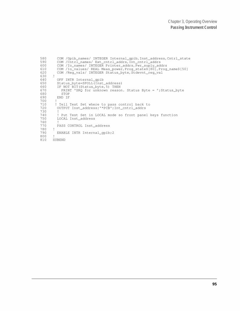
Chapter 3, Operating OverviewPassing Instrument Control
580 COM /Gpib_names/ INTEGER Internal_gpib,Inst_address,Cntrl_state590 COM /Cntrl_names/ Ext_cntrl_addrs,Int_cntrl_addrs600 COM /Io_names/ INTEGER Printer_addrs,Pwr_suply_addrs610 COM /Io_values/ REAL Meas_power,Prog_state$[80],Prog_name$[50]620 COM /Reg_vals/ INTEGER Status_byte,Stdevnt_reg_val630 !640 OFF INTR Internal_gpib650 Status_byte=SPOLL(Inst_address)660 IF NOT BIT(Status_byte,5) THEN670 PRINT "SRQ for unknown reason. Status Byte = ";Status_byte680 STOP690 END IF700 !710 ! Tell Test Set where to pass control back to720 OUTPUT Inst_address;"*PCB";Int_cntrl_addrs730 !740 ! Put Test Set in LOCAL mode so front panel keys function750 LOCAL Inst_address760 !770 PASS CONTROL Inst_address780 !790 ENABLE INTR Internal_gpib;2800 !810 SUBEND
95

Chapter 3, Operating OverviewPassing Instrument Control
The following IBASIC program would be loaded off the Memory Card and run in the Test Set:
10 COM /Gpib_names/ INTEGER Internal_gpib,External_gpib20 COM /Cntrl_names/ Ext_cntrl_addrs,Int_cntrl_addrs30 COM /Io_names/ INTEGER Printer_addrs,Pwr_suply_addrs40 COM /Io_values/ REAL Meas_power50 !60 Internal_gpib=80070 External_gpib=70080 Ext_cntrl_addrs=2190 Int_cntrl_addrs=14100 Printer_addrs=1110 Pwr_suply_addrs=26120 !130 OUTPUT Internal_gpib;"*RST"140 CLEAR SCREEN150 PRINTER IS CRT160 !170 EXECUTE ("REQUEST_CONTROL")180 !190 Try_again: !200 ON ERROR GOTO Not_actve_cntrl210 DISP "WAITING TO GET CONTROL"220 OUTPUT External_gpib;"" !If OUTPUT successful then Active Controller230 !If OUTPUT not successful then not Active Controller240 DISP "TEST SET NOW ACTIVE CONTROLLER."250 CALL Start_program260 !270 Pass_back: !280 DISP "PASSING CONTROL BACK"290 !Control is passed back automatically when the program stops300 !Control is passed back to address specified by *PCB command310 DISP "PROGRAM FINISHED"320 STOP330 !340 Not_actve_cntrl: !350 OFF ERROR360 DISP "CHECKING FOR ERROR"370 IF ERRN=173 THEN380 GOTO Try_again390 ELSE400 PRINT "ERROR =";ERRN410 STOP420 END IF430 !440 END450 !460 SUB Start_program470 !480 COM /Gpib_names/ INTEGER Internal_gpib,External_gpib490 COM /Cntrl_names/ Ext_cntrl_addrs,Int_cntrl_addrs500 COM /Io_names/ INTEGER Printer_addrs,Pwr_suply_addrs510 COM /Io_values/ REAL Meas_power520 !530 PRINT "SETTING POWER SUPPLY"540 OUTPUT External_gpib+Pwr_suply_addrs;"IMAX 8;ISET 5"550 OUTPUT External_gpib+Pwr_suply_addrs;"VMAX 15;VSET 13.2"560 !
570 PRINT "SETTING UP INTERNAL INSTRUMENTS"580 OUTPUT Internal_gpib;"RFG:FREQ 850.030 MHz;AMPL -40 dBm"
96
S:\agilent\e8285\USRGUIDE\BOOK\CHAPTERS\opoverv.fb
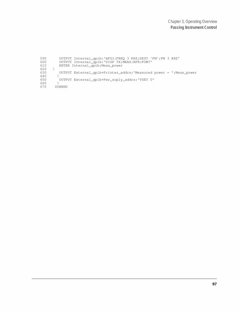
Chapter 3, Operating OverviewPassing Instrument Control
590 OUTPUT Internal_gpib;"AFG1:FREQ 3 KHZ;DEST ’FM’;FM 3 KHZ"600 OUTPUT Internal_gpib;"DISP TX;MEAS:RFR:POW?"610 ENTER Internal_gpib;Meas_power620 !630 OUTPUT External_gpib+Printer_addrs;"Measured power = ";Meas_power640 !650 OUTPUT External_gpib+Pwr_suply_addrs;"VSET 0"660 !670 SUBEND
97

Chapter 3, Operating OverviewPassing Instrument Control
98
S:\agilent\e8285\USRGUIDE\BOOK\CHAPTERS\opoverv.fb

4
Status Reporting
99

Chapter 4, Status Reporting
This chapter provides an overview of the status reporting structure used in the Test Set. Methods for using status register bits and bit definitions are also found here.
• "Status Reporting" on page 101• "GPIB Status Register Groups" on page 108• "Using Service Request (SRQ) Interrupts" on page 217• "Setting up an SRQ Interrupt" on page 218
100
S:\agilent\e8285\USRGUIDE\BOOK\CHAPTERS\hpibstat.fb
Chapter 4, Status ReportingStatus Reporting
tatus are status tus
The s of a , and
Status Reporting
This section describes the status reporting structure used in the Test Set. The structure is based on the IEEE 488.1-1987 and 488.2-1987 Standards and the Standard Commands for Programmable Instruments (SCPI) Version 1994.0.
For a full listing of command mnemonics, refer to the “Status” syntax, in GPIB Command Syntax chapter of the Agilent Technologies E8285A Condensed Programming Reference Guide.
Status Register Structure Overview
The structure of the register groups used in the Test Set is based upon the sdata structures outlined in the IEEE 488 and SCPI 1994.0 Standards. There two types of status data structures used in the Test Set: status registers and queues. The general models, components, and operation of each type of stadata structure are explained in the following sections.
Status Register Model
This section explains how the status registers are structured in the Test Set. generalized status register group model shown on the previous page consistCondition Register, Transition Filters, an Event Register, an Enable Registera Summary Message Bit.
101

Chapter 4, Status ReportingStatus Reporting
Figure 8 Status Data Structure - Register Group Model
- - -Test Set States Continuously Monitored - - -
15 14 2 01
15 14 2 01
15 14 2 01
&
LogicalOR
Summary MessageBit
Event EnableRegister(Selects which Eventscan set the SummaryMessage Bit)
Event Register(Latched Conditions)
Positive TransitionFilter
Negative TransitionFilter(Positive and NegativeTransition Filters select which transitions ofCondition Bits will setcorresponding Event Bits
Condition Register
&
&&
&
ch4drw3.ds4
102
S:\agilent\e8285\USRGUIDE\BOOK\CHAPTERS\hpibstat.fb
Chapter 4, Status ReportingStatus Reporting
of
ion from
bit ter. nt
t
0. in No he
sitive (all ).
Condition Register
A condition is a Test Set state that is either TRUE or FALSE (an GPIB command error has occurred or an GPIB command error has not occurred). Each bit in a Condition Register is assigned to a particular Test Set state. A Condition Register continuously monitors the hardware and firmware states assigned to it. There is no latching or buffering of any bits in a Condition Register; it is updated in real time. Condition Registers are read-only. Condition Registers in the Test Set are 16 bits long and may contain unused bits. All unused bits return a zero value when read.
Some status register groups do not implement Condition registers for certain Test Set conditions. In the tables labeled “Bit Definitions”, these conditions are indicated by the word “NO” in the column labeled “Is Condition Register Implemented?”.
Transition Filters
For each bit in the Condition Register, the Transition Filters determine whichtwo bit-state transitions will set the corresponding bit in the Event Register. Transition Filters may be set to pass positive transitions (PTR), negative transitions (NTR) or either (PTR or NTR). A positive transition means a conditbit changed from 0 to 1. A negative transition means a condition bit changed 1 to 0.
In the Test Set, the Transition Filters are implemented as two registers: a 16-positive transition (PTR) register and a 16-bit negative transition (NTR) regisA positive transition of a bit in the Condition register will be latched in the EveRegister if the corresponding bit in the positive transition filter is set to 1. A positive transition of a bit in the Condition register will not be latched in the EventRegister if the corresponding bit in the positive transition filter is set to 0. A negative transition of a bit in the Condition register will be latched in the EvenRegister if the corresponding bit in the negative transition filter is set to 1. A negative transition of a bit in the Condition register will not be latched in the Event Register if the corresponding bit in the negative transition filter is set toEither transition (PTR or NTR) of a bit in the Condition Register will be latchedthe Event Register if the corresponding bit in both transition filters is set to 1.transitions (PTR or NTR) of a bit in the Condition Register will be latched in tEvent Register if the corresponding bit in both transition filters is set to 0.
Transition Filters are read-write. Transition Filters are unaffected by a *CLS (clear status) command or queries. The Transitions Filters are set to pass potransitions (PTR) at power on and after receiving the *RST (reset) command16 bits of the PTR register set to 1 and all 16 bits of the NTR register set to 0
103

Chapter 4, Status ReportingStatus Reporting
e read-tain
ed to
sing mary roup are sed read clear
t one g of
ent its to
UE, ary . RUE.
Event Register
The Event Register captures bit-state transitions in the Condition Register as defined by the Transition Filters. Each bit in the Event Register corresponds to a bit in the Condition Register, or if there is no Condition Register/Transition Filter combination, each bit corresponds to a specific condition in the Test Set. Bits in the Event Register are latched, and, once set, they remain set until cleared by a query of the Event Register or a *CLS (clear status) command. This guarantees that the application can’t miss a bit-state transition in the Condition Register. There is no buffering; so while an event bit is set, subsequent transitions in thCondition Register corresponding to that bit are ignored. Event Registers areonly. Event Registers in the Test Set are either 8 or 16 bits long and may conunused bits. All unused bits return a zero value when read.
Event Enable Register
The Event Enable Register defines which bits in the Event Register will be usgenerate the Summary Message. Each bit in the Enable Register has a corresponding bit in the Event Register. The Test Set logically ANDs corresponding bits in the Event and Enable registers and then performs an inclusive OR on all the resulting bits to generate the Summary Message. By uthe enable bits the application program can direct the Test Set to set the SumMessage to the 1 or TRUE state for a single event or an inclusive OR of any gof events. Enable Registers are read-write. Enable Registers in the Test Set either 8 or 16 bits long and may contain unused bits which correspond to unubits in the associated Event Register. All unused bits return a zero value whenand are ignored when written to. Enable Registers are unaffected by a *CLS (status) command or queries.
Summary Message Bit
The Summary Message is a single-bit message which indicates whether or noor more of the enabled events have occurred since the last reading or clearinthe Event Register. The Test Set logically ANDs corresponding bits in the Evand Enable registers and then performs an inclusive OR on all the resulting bgenerate the Summary Message. By use of the enable bits, the application program can direct the Test Set to set the Summary Message to the 1, or TRstate for a single event or an inclusive OR of any group of events. The SummMessage is TRUE when an enabled event in the Event Register is set TRUEConversely, the Summary Message is FALSE when no enabled events are TSummary Messages are always seen as bits in another register.
104
S:\agilent\e8285\USRGUIDE\BOOK\CHAPTERS\hpibstat.fb

Chapter 4, Status ReportingStatus Reporting
Status Queue Model
This section explains how status queues are structured in the Test Set. The generalized status queue model shown in figure 9 is the basis upon which all the status queues in the Test Set are built. A queue is a data structure containing a sequential list of information. The queue is empty when all information has been read from the list. The associated Summary Message is TRUE, logic 1, if the queue contains some information and FALSE, logic 0, if the queue is empty. Queues can be cleared by reading all the information from the queue. Queues, except the Output Queue, can also be cleared using the *CLS (clear status) command. A status queue can also be referred to as a Status Register Group.
Figure 9 Status Data Structure - Queue Mode
data
Summary Message Bit
Queue Empty = "0"Queue Not - Empty = "1"
ch4drw04.drw
Queue
data
data
data
data
data
105

Chapter 4, Status ReportingStatus Reporting
Status Register Programming Considerations
When performing certain tasks, such as making a call, program flow can be controlled by the status register group bits. Generally, there are two approaches to using status register group bits, Polling, and Service Requests. The choice of which technique to use, polling or service request, will depend upon the needs of the particular application.
Advantages/Disadvantages of Polling
Polling has the advantage that the control program can react quicker to the change in state since it (the control program) does not have to execute the code necessary to determine what condition caused the service request line to be asserted.
Polling has the disadvantage that, if improperly implemented, it can prevent the Call Processing Subsystem from properly interfacing with the mobile station.
The Test Set has a multi-tasking architecture wherein multiple processes execute on a priority driven and an event driven basis. One of the highest priority processes is the process that services the GPIB.
If a control program constantly polls the status registers to determine when a particular state is true, that state may never go to the true state because the Test Set is constantly being interrupted by the GPIB service process.
Therefore, care must be exercised when using the polling technique to allow enough time between polls for processes to execute within the Test Set.
Some computer systems and/or programming languages may not support the service request feature of the GPIB and consequently polling would be the only technique available to the programmer. When using a polling technique be sure to include a delay in the polling loop. Refer to line 60 in the following example.
106
S:\agilent\e8285\USRGUIDE\BOOK\CHAPTERS\hpibstat.fb

Chapter 4, Status ReportingStatus Reporting
HP® BASIC Example of Polling10 PRINT “PRESS CONTINUE WHEN THE MOBILE STATION IS IN IDLE STATE”15 OUTPUT 714;”*CLS” !Clears contents of event registers20 PAUSE30 OUTPUT 714;”CDMA:MOB:REG” !Attempts to register mobile station40 DISP “Registering mobile station”50 REPEAT60 WAIT .1 !Allows the Test Set to perform processes other than processing GPIB commands 70 OUTPUT 714;”STAT:CDMA:EVEN?” !Queries the CDMA Event register80 ENTER 714;Cdma_event_reg90 UNTIL BIT(Cdma_event_reg,11) !Exits loop when Mobile Station Registered bit goes true100 PRINT “MOBILE STATION HAS REGISTERED”110 END
Advantages/Disadvantages of Using Service Request
The service request feature of the GPIB has the advantage that it allows the Call Processing Subsystem to execute at its maximum speed since processes within the subsystem are not being constantly interrupted by the need to service the GPIB.
The service request feature of the GPIB has the disadvantage that it takes more code to implement within the control program. The consequence of which is a slight reduction in the overall throughput of the control program since more code must be executed to accomplish the same task. For an example of using the service request feature, refer to “Controlling Program Flow” chapter in the E8285A Application Guide.
107

Chapter 4, Status ReportingGPIB Status Register Groups
GPIB Status Register Groups
Figure 10 Test Set Data Structure Block Diagram
0
1
2
3
MAV
ESB
7
RQS MSS
0
1
2
3
MAV
ESB
7
Logi
cal O
R
Logi
cal O
R
Hardware Status Register #1 Group
Logi
cal O
R
Hardware Status Register #2 Group
Logi
cal O
RQuestionable Data/Signal Register Group
Logi
cal O
R
Standard EventStatus Register Group
Logi
cal O
R
Operation Status Register Group
Logi
cal O
R
Communicate Status Register Group
Logi
cal O
R
Calibration Status Register Group
8
TR EV EN
SMB
C TR EV EN
9
TR EV EN
EV EN
EV EN
data
data
Output Queue
SMB
Status Byte Register Group
SMB
SMB
SMB
SMB
SMB
SMB
SMB
Notes: C = Condition Register TR = Transition Filter Registers (Pos. and Neg.) EV = Event Register EN = Enable RegisterSMB = Summary Message Bit
C TR EV EN
C TR EV EN
C TR EV EN
datstruc.ds4
Logi
cal O
R
Measuring Status Register Group
SMB
C TR EV EN
Logi
cal O
R
Call Processing Status Register Group
SMB
C TR EV EN
Logi
cal O
R
Calibrating Status Register Group
SMB
C TR EV EN
Logi
cal O
R
SMB
C TR EV EN
Logi
cal O
R
Serial #1 Status Register Group
SMB
C TR EV EN
Logi
cal O
R
CDMA Status Register Group
SMB
C TR EV EN
8
40
Serial #2 Status Register Group
9 6
8
10
Logi
cal O
R
CDMA_2 Status Register Group
SMB
C TR EV EN
0
Logi
cal O
R
SMB
C TR EV EN
Logi
cal O
R
Open Loop Time Response Status Register Group
SMB
C TR EV EN
CDMA SMS Status Register Group
1
C
Logi
cal O
R
CDMA_1 Status Register Group
SMB
C TR EV EN
2
Logi
cal O
R
Power Status Register Group
SMB
C TR EV EN 3
Logi
cal O
R
CDMA Authentication Status Register Group
SMB
C TR EV EN
3
108
S:\agilent\e8285\USRGUIDE\BOOK\CHAPTERS\hpibstat.fb

Chapter 4, Status ReportingGPIB Status Register Groups
Calibrating Status Register Group
The Calibrating Status Register Group contains information about events associated with calibrating CDMA measurements. This register group uses 16-bit registers and includes a Condition Register, Transition Filters, an Event Register, an Enable Register, and a Summary Message. p.
The Calibrating Register Group SMB must be enabled in the Operation Status Register Group before any of the following events or conditions can be reported through the Status Byte Register.
Figure 11 on page 110 shows the structure and STATus commands for the Calibrating Status Register Group.
Table 5 on page 116 details the Calibrating Status Register Group Condition Register bit assignments.
109
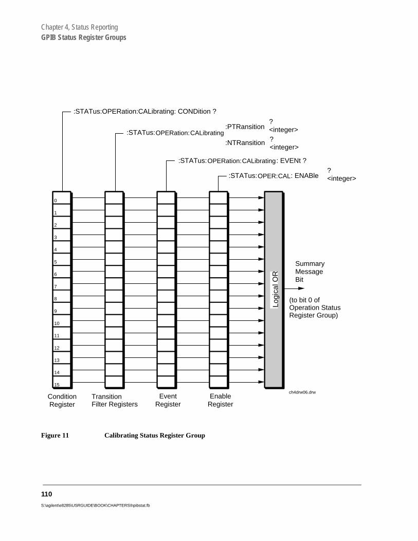
Chapter 4, Status ReportingGPIB Status Register Groups
Figure 11 Calibrating Status Register Group
0
:STATus:OPER:CAL: ENABle?<integer>
:STATus:OPERation:CALibrating: EVENt ?
:STATus:OPERation:CALibrating:PTRansition
:NTRansition
?<integer>?<integer>
:STATus:OPERation:CALibrating: CONDition ?
SummaryMessageBit
ConditionRegister
TransitionFilter Registers
EventRegister
EnableRegister
1
2
3
4
5
6
7
8
9
10
11
12
13
14
Logi
cal O
R
15
(to bit 0 ofOperation StatusRegister Group)
ch4drw06.drw
110
S:\agilent\e8285\USRGUIDE\BOOK\CHAPTERS\hpibstat.fb
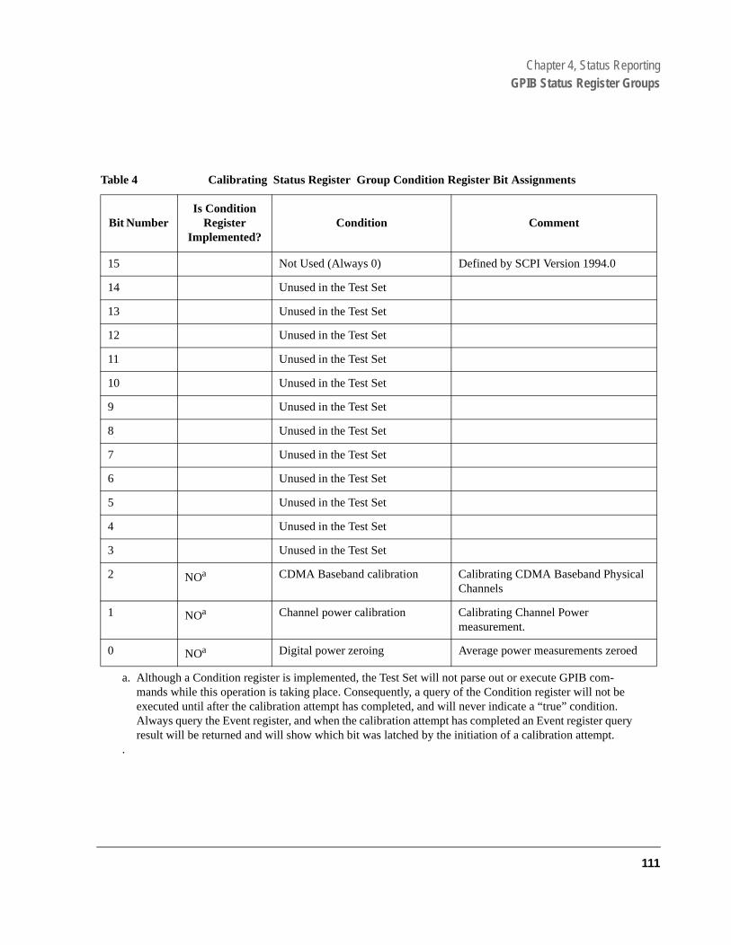
Chapter 4, Status ReportingGPIB Status Register Groups
ry
Table 4 Calibrating Status Register Group Condition Register Bit Assignments
Bit Number Is Condition
Register Implemented?
Condition Comment
15 Not Used (Always 0) Defined by SCPI Version 1994.0
14 Unused in the Test Set
13 Unused in the Test Set
12 Unused in the Test Set
11 Unused in the Test Set
10 Unused in the Test Set
9 Unused in the Test Set
8 Unused in the Test Set
7 Unused in the Test Set
6 Unused in the Test Set
5 Unused in the Test Set
4 Unused in the Test Set
3 Unused in the Test Set
2 NOa CDMA Baseband calibration Calibrating CDMA Baseband Physical Channels
1 NOa
a. Although a Condition register is implemented, the Test Set will not parse out or execute GPIB com-mands while this operation is taking place. Consequently, a query of the Condition register will not be executed until after the calibration attempt has completed, and will never indicate a “true” condition. Always query the Event register, and when the calibration attempt has completed an Event register queresult will be returned and will show which bit was latched by the initiation of a calibration attempt.
.
Channel power calibration Calibrating Channel Power measurement.
0 NOa Digital power zeroing Average power measurements zeroed
111
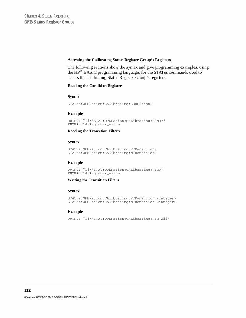
Chapter 4, Status ReportingGPIB Status Register Groups
Accessing the Calibrating Status Register Group’s Registers
The following sections show the syntax and give programming examples, using the HP® BASIC programming language, for the STATus commands used to access the Calibrating Status Register Group’s registers.
Reading the Condition Register
Syntax
STATus:OPERation:CALibrating:CONDition?
Example
OUTPUT 714;"STAT:OPERation:CALibrating:COND?"ENTER 714;Register_value
Reading the Transition Filters
Syntax
STATus:OPERation:CALibrating:PTRansition?STATus:OPERation:CALibrating:NTRansition?
Example
OUTPUT 714;"STAT:OPERation:CALibrating:PTR?"ENTER 714;Register_value
Writing the Transition Filters
Syntax
STATus:OPERation:CALibrating:PTRansition <integer>STATus:OPERation:CALibrating:NTRansition <integer>
Example
OUTPUT 714;"STAT:OPERation:CALibrating:PTR 256"
112
S:\agilent\e8285\USRGUIDE\BOOK\CHAPTERS\hpibstat.fb
Chapter 4, Status ReportingGPIB Status Register Groups
Reading the Event Register
Syntax
STATus:OPERation:CALibrating:EVENt?
Example
OUTPUT 714;"STAT:OPERation:CALibrating:EVEN?"ENTER 714;Register_value
Clearing the Event Register
The EVENT register is cleared whenever it is queried or whenever the Common Command *CLS is sent to the Test Set.
Reading the Enable Register
Syntax
STATus:OPERation:CALibrating:ENABle?
Example
OUTPUT 714;"STAT:OPERation:CALibrating:ENAB?"ENTER 714;Register_value
Writing the Enable Register
Syntax
STATus:OPERation:CALibrating:ENABle <integer>
Example
OUTPUT 714;"STAT:OPERation:CALibrating:ENAB 256"
Clearing the Enable Register
The ENABLE register is cleared by writing to it with an integer value of zero.
113
Chapter 4, Status ReportingGPIB Status Register Groups
et’s
Status bled wing
Calibration Status Register Group
The Calibration Status Register Group contains information about the Test Shardware.
The Status Byte Register summary message associated with the Calibration Register Group is bit three. The Calibration Register Group SMB must be enain the Questionable Data/Signal Status Register Group before any of the folloevents or conditions can be reported through the Status Byte Register.
Figure 12 on page 115 shows the structure and STATus commands for the Calibration Status Register Group.
Table 5 on page 116 details the Calibration Status Register Group Condition Register bit assignments.
114
S:\agilent\e8285\USRGUIDE\BOOK\CHAPTERS\hpibstat.fb
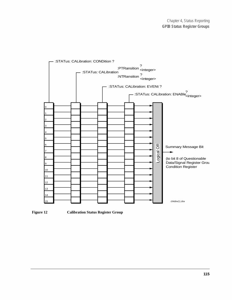
Chapter 4, Status ReportingGPIB Status Register Groups
Figure 12 Calibration Status Register Group
0
:STATus: CALibration: ENABle?<integer>
:STATus: CALibration: EVENt ?
:STATus: CALibration:PTRansition
:NTRansition
?<integer>?<integer>
:STATus: CALibration: CONDition ?
Summary Message Bit
C T i i E E bl
1
2
3
4
5
6
7
8
9
10
11
12
13
14
Logi
cal O
R
15 ch4drw11.drw
(to bit 8 of QuestionableData/Signal Register GrouCondition Register
115

Chapter 4, Status ReportingGPIB Status Register Groups
Accessing the Calibration Status Register Group Registers
Table 5 Calibration Status Register Group Bit Assignments
Bit Number
Is Condition Register
Implemented? Condition/Event Comment
15 Not Used (Always 0) Defined by SCPI Version 1994.0
14 Unused in the Test Set
13 Unused in the Test Set
12 Unused in the Test Set
11 Unused in the Test Set
10 Unused in the Test Set
9 Unused in the Test Set
8 NO PCB Calibration Failed
7 NO CDMA Channel Power Port Error
6 NO CDMA Channel Power Calibration Failure
5 NO CDMA Digital Power Zero Failure An attempt to zero the CDMA Average Power measurement failed.
4 NO TX Power Auto-Zero Failure
3 YES Voltmeter Self-Calibration Failure
2 YES Counter Self-Calibration Failure
1 YES Sampler Self-Calibration Failure
0 YES Spectrum Analyzer Self-Calibration Failure
116
S:\agilent\e8285\USRGUIDE\BOOK\CHAPTERS\hpibstat.fb
Chapter 4, Status ReportingGPIB Status Register Groups
The following sections show the syntax and give programming examples, using the HP® BASIC programming language, for the STATus commands used to access the Calibration Status Register Group registers.
Reading the Condition Register
Syntax
STATus:CALibration:CONDition?
Example
OUTPUT 714;”STAT:CAL:COND?”ENTER 714;Register_value
Reading the Transition Filters
Syntax
STATus:CALibration:PTRansition?STATus:CALibration:NTRansition?
Example
OUTPUT 714;”STAT:CAL:PTR?”ENTER 714;Register_value
Writing the Transition Filters
Syntax
STATus:CALibration:PTRansition <integer>STATus:CALibration:NTRansition <integer>
Example
OUTPUT 714;”STAT:CAL:PTR 256”
117

Chapter 4, Status ReportingGPIB Status Register Groups
Reading the Event Register
Syntax
STATus:CALibration:EVENt?
Example
OUTPUT 714;”STAT:CAL:EVEN?”ENTER 714;Register_value
Clearing the Event Register
The EVENT register is cleared whenever it is queried or whenever the Common Command *CLS is sent to the Test Set.
Reading the Enable Register
Syntax
STATus:CALibration:ENABle?
Example
OUTPUT 714;”STAT:CAL:ENAB?”ENTER 714;Register_value
Writing the Enable Register
Syntax
STATus:CALibration:ENABle <integer>
Example
OUTPUT 714;”STAT:CAL:ENAB 256”
Clearing the Enable Register
The ENABLE register is cleared by writing to it with an integer value of zero.
118
S:\agilent\e8285\USRGUIDE\BOOK\CHAPTERS\hpibstat.fb

Chapter 4, Status ReportingGPIB Status Register Groups
TATus and le
r bit
Call Processing Status Register Group
The Call Processing Status Register Group contains information about the Test Set’s Call Processing Subsystem. This status group is accessed using the Scommands. The Call Processing Status Register Group uses 16-bit registersincludes a Condition Register, Transition Filters, an Event Register, an EnabRegister, and a Summary Message Bit.
Figure 12 shows the structure and STATus commands for the Call ProcessingStatus Register Group.
Refer to the "Status Register Structure Overview" on page 101 for a discussion of status register operation.
Table 5 details the Call Processing Status Register Group’s Condition Registeassignments.
119

Chapter 4, Status ReportingGPIB Status Register Groups
Figure 13 Calibration Status Register Group
0
:STATus: CALLProc : ENABle?<integer>
:STATus: CALLProc : EVENt ?
:STATus: CALLProc:PTRansition
:NTRansition
?<integer>?<integer>
:STATus: CALLProc: CONDition ?
Summary Message Bit
ConditionRegister
TransitionFilter Registers
EventRegister
EnableRegister
1
2
3
4
5
6
7
8
9
10
11
12
13
14
Logi
cal O
R
15
ch4drw18.ds4
(to bit 9 of OperationStatus Register GroupCondition Register
120
S:\agilent\e8285\USRGUIDE\BOOK\CHAPTERS\hpibstat.fb

Chapter 4, Status ReportingGPIB Status Register Groups
Table 6 Call Processing Status Register Group, Condition Register Bit Assignments
Bit Number
Is Condition Register
Implemented? Condition Comment
15 Not Used (Always 0) Defined by SCPI Version 1994.0
14 Unused in the Test Set
13 Unused in the Test Set
12 Unused in the Test Set
11 Unused in the Test Set
10 Unused in the Test Set
9 Unused in the Test Set
8 Unused in the Test Set
7 Unused in the Test Set
6 YES Mobile station ringing. Bit state goes true (1) after a base station originated call is attempted and the call processing state has progressed past Access. Answering the call from the mobile station causes the bit state to go false (0).
5 YES Call Processing Connect State Bit state mirrors the condition of the Connected annunciator on the CRT display (1=ON, 0=OFF)
4 YES Call Processing Access State Bit state mirrors the condition of the Access annunciator on the CRT display (1=ON, 0=OFF)
3 YES Call Processing Page State Bit state mirrors the condition of the Page annunciator on the CRT display (1=ON, 0=OFF)
2 YES Call Processing Authentication State Call processing is authenticating
1 YES Call Processing Registration State bit state mirrors the condition of the Register annunciator on the CRT display (1=ON, 0=OFF)
121
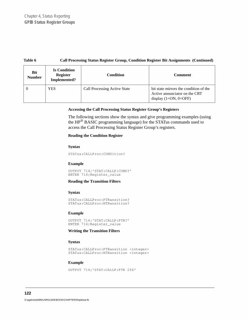
Chapter 4, Status ReportingGPIB Status Register Groups
Accessing the Call Processing Status Register Group’s Registers
The following sections show the syntax and give programming examples (using the HP® BASIC programming language) for the STATus commands used to access the Call Processing Status Register Group’s registers.
Reading the Condition Register
Syntax
STATus:CALLProc:CONDition?
Example
OUTPUT 714;"STAT:CALLP:COND?"ENTER 714;Register_value
Reading the Transition Filters
Syntax
STATus:CALLProc:PTRansition?STATus:CALLProc:NTRansition?
Example
OUTPUT 714;"STAT:CALLP:PTR?"ENTER 714;Register_value
Writing the Transition Filters
Syntax
STATus:CALLProc:PTRansition <integer>STATus:CALLProc:NTRansition <integer>
Example
OUTPUT 714;"STAT:CALLP:PTR 256"
0 YES Call Processing Active State bit state mirrors the condition of the Active annunciator on the CRT display (1=ON, 0=OFF)
Table 6 Call Processing Status Register Group, Condition Register Bit Assignments (Continued)
Bit Number
Is Condition Register
Implemented? Condition Comment
122
S:\agilent\e8285\USRGUIDE\BOOK\CHAPTERS\hpibstat.fb

Chapter 4, Status ReportingGPIB Status Register Groups
Reading the Event Register
Syntax
STATus:CALLProc:EVENt?
Example
OUTPUT 714;"STAT:CALLP:EVEN?"ENTER 714;Register_value
Clearing the Event Register
The EVENT register is cleared whenever it is queried or whenever the Common Command *CLS is sent to the Test Set.
Reading the Enable Register
Syntax
STATus:CALLProc:ENABle?
Example
OUTPUT 714;"STAT:CALLP:ENAB?"ENTER 714;Register_value
Writing the Enable Register
Syntax
STATus:CALLProc:ENABle <integer>
Example
OUTPUT 714;"STAT:CALLP:ENAB 256"
Clearing the Enable Register
The ENABLE register is cleared by writing to it with an integer value of zero.
123

Chapter 4, Status ReportingGPIB Status Register Groups
CDMA Status Register Group
The CDMA Status Register Group contains information about various signaling events.
The CDMA Status Register SMB must be enabled in the Operation Status Register Group before any of the following events or conditions can be reported through the Status Byte Register.
Figure 16 shows the structure and STATus commands for the CDMA Status Register Group.
Table 9 shows the CDMA Status Register Group bit assignments.
124
S:\agilent\e8285\USRGUIDE\BOOK\CHAPTERS\hpibstat.fb
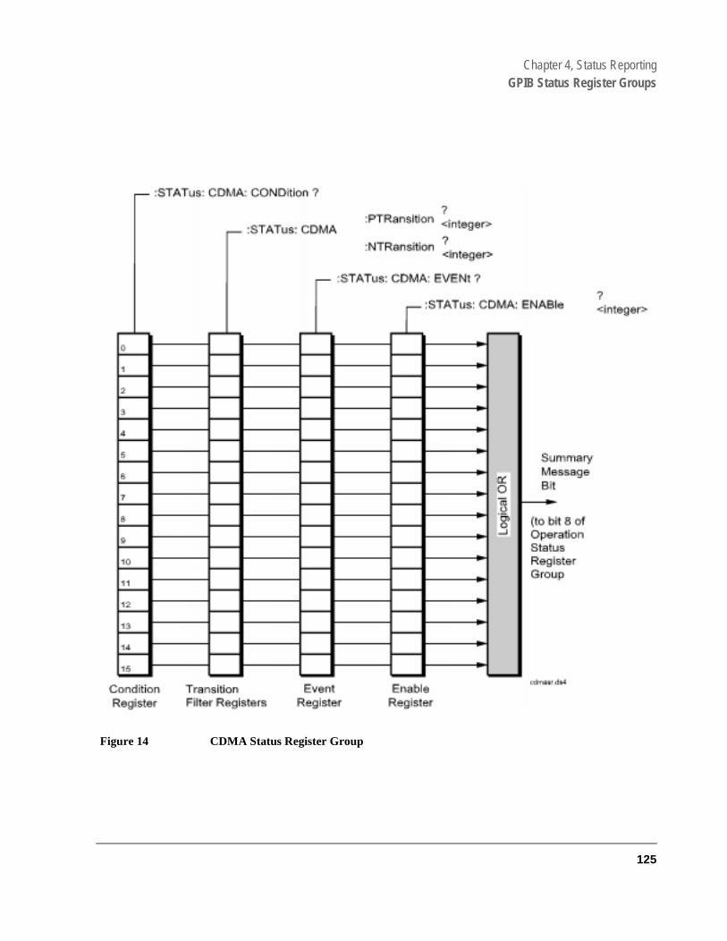
Chapter 4, Status ReportingGPIB Status Register Groups
Figure 14 CDMA Status Register Group
125

Chapter 4, Status ReportingGPIB Status Register Groups
Table 7 CDMA Status Register Group Bit Assignments
Bit Number Is Condition
Register Implemented?
Condition/Event Comment
15 Not Used (Always 0) Defined by SCPI Version 1994.0
14 YES CDMA Power Control Ramping
13 NO MS Reported FER Received This event register bit will be set to a logic 1 when the MSUT reports FER. MS reported FER is influenced by the MS FER Report Interval fields.
12 NO Pilot Strength Message Received This event register bit will be set to a logic 1 when the Test Set receives a Pilot Strength message from the MSUT. Each Pilot Strength message will update the CDMA Mobile Reporting table, which displays the Status, PN Offset, Strength, and Keep bit for CDMA pilot signals.
11 NO CDMA Mobile Registered This event register bit will be set to a logic 1 when the front panel display annunciator “Registering” goes out, indicating the mobile station has registered.
10 NO CDMA FER Test Passed
9 NO CDMA FER Test Failed
8 NO CDMA FER Test Max Frames
7 YES CDMA Service Option 2
6 YES CDMA Hard Handoff
5 YES CDMA Softer Handoff
4 YES CDMA Call Alert The Alerting Condition Register bit will be set to logic 1 while the MSUT is ringing. This only occurs during a Service Option 1 call from the Test Set (MSUT terminated).
126
S:\agilent\e8285\USRGUIDE\BOOK\CHAPTERS\hpibstat.fb

Chapter 4, Status ReportingGPIB Status Register Groups
r
3 YES CDMA Call Connected The “Connected” Condition Register bit will be set to a logic 1 when a call is connected. See the Connected (annunciator) field description in the E8285A Reference Guide.
2 YES CDMA Cell Transmitting The “Transmitting” Condition Register bit will be set to a logic 1 when the Test Set is in CDMA mode. See "CDMA and Analog Modes" on page 21.
1 YES CDMA Page Sent The “Page Sent” Condition Register bitwill be set to a logic 1 when the Call key is pressed or the corresponding GPIB command is sent. This Condition bit will remain 1 until the current call or call attempt has ended. See the Page Sent (annunciator) field description in the E8285A Reference Guide.
0 YES Access Probe Received The “Access Probe” Condition Registebit will be set to a logic 1 when a mobile station sends an access probe sequence to the Test Set.. This Condi-tion bit will remain 1 until the current call or call attempt has ended. See the Access Probe (annunciator) field description in the HP E8285A Reference Guide.
Table 7 CDMA Status Register Group Bit Assignments (Continued)
Bit Number Is Condition
Register Implemented?
Condition/Event Comment
127

Chapter 4, Status ReportingGPIB Status Register Groups
Accessing the CDMA Status Register Group Registers
The following sections show the syntax and give programming examples, using the HP® BASIC programming language, for the STATus commands used to access the CDMA Status Register Group registers.
Reading the Condition Register
Syntax
STATus:CDMA:CONDition?
Example
OUTPUT 714;”STAT:CDMA:COND?”ENTER 714;Register_value
Reading the Transition Filters
Syntax
STATus:CDMA:PTRansition?STATus:CDMA:NTRansition?
Example
OUTPUT 714;”STAT:CDMA:PTR?”ENTER 714;Register_value
Writing the Transition Filters
Syntax
STATus:CDMA:PTRansition <integer>STATus:CDMA:NTRansition <integer>
Example
OUTPUT 714;”STAT:CDMA:PTR 256”
128
S:\agilent\e8285\USRGUIDE\BOOK\CHAPTERS\hpibstat.fb

Chapter 4, Status ReportingGPIB Status Register Groups
Reading the Event Register
Syntax
STATus:CDMA:EVENt?
Example
OUTPUT 714;”STAT:CDMA:EVEN?”ENTER 714;Register_value
Clearing the Event Register
The EVENT register is cleared whenever it is queried or whenever the Common Command *CLS is sent to the Test Set.
Reading the Enable Register
Syntax
STATus:CDMA:ENABle?
Example
OUTPUT 714;”STAT:CDMA:ENAB?”ENTER 714;Register_value
Writing the Enable Register
Syntax
STATus:CDMA:ENABle <integer>
Example
OUTPUT 714;”STAT:CDMA:ENAB 256”
Clearing the Enable Register
The ENABLE register is cleared by writing to it with an integer value of zero.
129

Chapter 4, Status ReportingGPIB Status Register Groups
CDMA Authentication Status Register Group
The CDMA Authentication Status Register Group contains information about the status of authentication tests.
Figure 15 shows the structure and STATus commands for the CDMA Authentication Status Register Group.
Table 8 shows the CDMA Authentication Status Register Group bit assignments.
130
S:\agilent\e8285\USRGUIDE\BOOK\CHAPTERS\hpibstat.fb

Chapter 4, Status ReportingGPIB Status Register Groups
Figure 15 CDMA Authentication Status Register Group
:CONDition?
131

Chapter 4, Status ReportingGPIB Status Register Groups
Table 8 CDMA Authentication Status Register Group Bit Assignments
Bit Number Is Condition
Register Implemented?
Condition/Event Comment
15 Not Used (Always 0) Defined by SCPI Version 1994.0
14 NO Count Res. Included
13 Unused in the Test Set
12 NO Data Burst Message Received
11 NO SSD Update Received
10 NO Unique Challenge Received
9 NO Origination Received
8 NO Page Received
7 NO Registration Received
6 Unused in the Test Set
5 Unused in the Test Set
4 Unused in the Test Set
3 YES SSD_A=0
2 YES Unique Challenge in Progress
1 YES SSD Update in Progress
0 YES Authentication in Progress
132
S:\agilent\e8285\USRGUIDE\BOOK\CHAPTERS\hpibstat.fb

Chapter 4, Status ReportingGPIB Status Register Groups
Accessing the CDMA Authentication Status Register Group Registers
The following sections show the syntax and give programming examples, using the HP® BASIC programming language, for the STATus commands used to access the CDMA Authentication Status Register Group registers.
Reading the Condition Register
Syntax
STATus:CAUT:CONDition?
Example
OUTPUT 714;”STAT:CAUT:COND?”ENTER 714;Register_value
Reading the Transition Filters
Syntax
STATus:CAUT:PTRansition?STATus:CAUT:NTRansition?
Example
OUTPUT 714;”STAT:CAUT:PTR?”ENTER 714;Register_value
Writing the Transition Filters
Syntax
STATus:CAUT:PTRansition <integer>STATus:CAUT:NTRansition <integer>
Example
OUTPUT 714;”STAT:CAUT:PTR 1”
133

Chapter 4, Status ReportingGPIB Status Register Groups
Reading the Event Register
Syntax
STATus:CAUT:EVENt?
Example
OUTPUT 714;”STAT:CAUT:EVEN?”ENTER 714;Register_value
Clearing the Event Register
The EVENT register is cleared whenever it is queried or whenever the Common Command *CLS is sent to the Test Set.
Reading the Enable Register
Syntax
STATus:CAUT:ENABle?
Example
OUTPUT 714;”STAT:CAUT:ENAB?”ENTER 714;Register_value
Writing the Enable Register
Syntax
STATus:CAUT:ENABle <integer>
Example
OUTPUT 714;”STAT:CAUT:ENAB 256”
Clearing the Enable Register
The ENABLE register is cleared by writing to it with an integer value of zero.
134
S:\agilent\e8285\USRGUIDE\BOOK\CHAPTERS\hpibstat.fb

Chapter 4, Status ReportingGPIB Status Register Groups
CDMA SMS Status Register Group
The CDMA Status Register Group reports the status of SMS (Short Message Service) operations.
Figure 16 shows the structure and STATus commands for the CDMA SMS Status Register Group.
Table 9 shows the CDMA Status Register Group bit assignments.
135
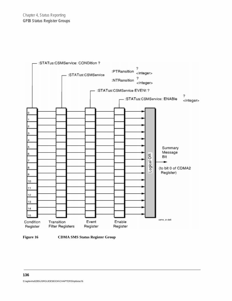
Chapter 4, Status ReportingGPIB Status Register Groups
Figure 16 CDMA SMS Status Register Group
136
S:\agilent\e8285\USRGUIDE\BOOK\CHAPTERS\hpibstat.fb

Chapter 4, Status ReportingGPIB Status Register Groups
Table 9 CDMA SMS Status Register Group Bit Assignments
Bit Number Is Condition
Register Implemented?
Condition/Event Comment
15 Not Used (Always 0) Defined by SCPI Version 1994.0
14 Unused in the Test Set
13 Unused in the Test Set
12 Unused in the Test Set
11 Unused in the Test Set
10 Unused in the Test Set
9 Unused in the Test Set
8 Unused in the Test Set
7 Unused in the Test Set
6 Unused in the Test Set
5 Unused in the Test Set
4 Unused in the Test Set
3 Unused in the Test Set
2 NO SMS Origination Received
1 NO CDMA SMS Acknowledge Received
The mobile station acknowledged receiving an SMS message
0 YES SMS Register An SMS message was sent and the Test Set is waiting for SMS message acknowledgement.
137

Chapter 4, Status ReportingGPIB Status Register Groups
Accessing the CDMA SMS Status Register Group Registers
The following sections show the syntax and give programming examples, using the HP® BASIC programming language, for the STATus commands used to access the CDMA SMS Status Register Group registers.
Reading the Condition Register
Syntax
STATus:CSMS:CONDition?
Example
OUTPUT 714;”STAT:CSMS:COND?”ENTER 714;Register_value
Reading the Transition Filters
Syntax
STATus:CSMS:PTRansition?STATus:CSMS:NTRansition?
Example
OUTPUT 714;”STAT:CSMS:PTR?”ENTER 714;Register_value
Writing the Transition Filters
Syntax
STATus:CSMS:PTRansition <integer>STATus:CSMS:NTRansition <integer>
Example
OUTPUT 714;”STAT:CSMS:PTR 1”
138
S:\agilent\e8285\USRGUIDE\BOOK\CHAPTERS\hpibstat.fb

Chapter 4, Status ReportingGPIB Status Register Groups
Reading the Event Register
Syntax
STATus:CSMS:EVENt?
Example
OUTPUT 714;”STAT:CSMS:EVEN?”ENTER 714;Register_value
Clearing the Event Register
The EVENT register is cleared whenever it is queried or whenever the Common Command *CLS is sent to the Test Set.
Reading the Enable Register
Syntax
STATus:CSMS:ENABle?
Example
OUTPUT 714;”STAT:CSMS:ENAB?”ENTER 714;Register_value
Writing the Enable Register
Syntax
STATus:CSMS:ENABle <integer>
Example
OUTPUT 714;”STAT:CSMS:ENAB 256”
Clearing the Enable Register
The ENABLE register is cleared by writing to it with an integer value of zero.
139
Chapter 4, Status ReportingGPIB Status Register Groups
CDMA_1 Status Register Group
The CDMA_1 Status Register Group provides a path for summary messages to the Hardware #1 Register Group at bit 2.
Figure 17 shows the structure and STATus commands for the CDMA_1 Status Register Group.
Table 10 shows the CDMA_1 Status Register Group bit assignments.
140
S:\agilent\e8285\USRGUIDE\BOOK\CHAPTERS\hpibstat.fb

Chapter 4, Status ReportingGPIB Status Register Groups
Figure 17 CDMA_1 Status Register Group
0
:STATus: CDMA1: ENABle?<integer>
:STATus: CDMA1: EVENt ?
:STATus: CDMA1:PTRansition
:NTRansition
?<integer>?<integer>
:STATus: CDMA1: CONDition ?
SummaryMessageBit
ConditionRegister
TransitionFilter Registers
EventRegister
EnableRegister
1
2
3
4
5
6
7
8
9
10
11
12
13
14
Logi
cal O
R
15
(to bit 2 ofHardware StatusRegisterGroup #1)
cdma1sr.ds4
141

Chapter 4, Status ReportingGPIB Status Register Groups
Table 10 CDMA_1 Status Register Group Bit Assignments
Bit Number Is Condition
Register Implemented?
Condition/Event Comment
15 Not Used (Always 0) Defined by SCPI Version 1994.0
14 Unused in the Test Set
13 Unused in the Test Set
12 Unused in the Test Set
11 Unused in the Test Set
10 Unused in the Test Set
9 Unused in the Test Set
8 Unused in the Test Set
7 Unused in the Test Set
6 Unused in the Test Set
5 Unused in the Test Set
4 Unused in the Test Set
3 YES CDMA Minimizer Error
2 YES Miscellaneous DSP Error .
1 YES CDMA Correlation Error
0 YES CDMA ADC Overdrive Error
142
S:\agilent\e8285\USRGUIDE\BOOK\CHAPTERS\hpibstat.fb

Chapter 4, Status ReportingGPIB Status Register Groups
Accessing the CDMA_1 Status Register Group Registers
The following sections show the syntax and give programming examples, using the HP® BASIC programming language, for the STATus commands used to access the CDMA_1 Status Register Group registers.
Reading the Condition Register
Syntax
STATus:CDMA1:CONDition?
Example
OUTPUT 714;”STAT:CDMA1:COND?”ENTER 714;Register_value
Reading the Transition Filters
Syntax
STATus:CDMA1:PTRansition?STATus:CDMA1:NTRansition?
Example
OUTPUT 714;”STAT:CDMA1:PTR?”ENTER 714;Register_value
Writing the Transition Filters
Syntax
STATus:CDMA1:PTRansition <integer>STATus:CDMA1:NTRansition <integer>
Example
OUTPUT 714;”STAT:CDMA1:PTR 1”
143

Chapter 4, Status ReportingGPIB Status Register Groups
Reading the Event Register
Syntax
STATus:CDMA1:EVENt?
Example
OUTPUT 714;”STAT:CDMA1:EVEN?”ENTER 714;Register_value
Clearing the Event Register
The EVENT register is cleared whenever it is queried or whenever the Common Command *CLS is sent to the Test Set.
Reading the Enable Register
Syntax
STATus:CDMA1:ENABle?
Example
OUTPUT 714;”STAT:CDMA1:ENAB?”ENTER 714;Register_value
Writing the Enable Register
Syntax
STATus:CDMA1:ENABle <integer>
Example
OUTPUT 714;”STAT:CDMA1:ENAB 256”
Clearing the Enable Register
The ENABLE register is cleared by writing to it with an integer value of zero.
144
S:\agilent\e8285\USRGUIDE\BOOK\CHAPTERS\hpibstat.fb

Chapter 4, Status ReportingGPIB Status Register Groups
CDMA_2 Status Register Group
The CDMA_2 Status Register Group provides a path for summary messages to the Operation Status Register.
Figure 18 shows the structure and STATus commands for the CDMA_2 Status Register Group.
Table 11 shows the CDMA_2 Status Register Group bit assignments.
145
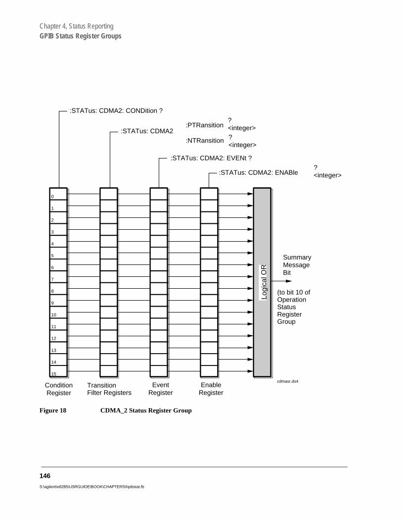
Chapter 4, Status ReportingGPIB Status Register Groups
Figure 18 CDMA_2 Status Register Group
0
:STATus: CDMA2: ENABle?<integer>
:STATus: CDMA2: EVENt ?
:STATus: CDMA2:PTRansition
:NTRansition
?<integer>?<integer>
:STATus: CDMA2: CONDition ?
SummaryMessageBit
ConditionRegister
TransitionFilter Registers
EventRegister
EnableRegister
1
2
3
4
5
6
7
8
9
10
11
12
13
14
Logi
cal O
R
15
(to bit 10 ofOperationStatusRegisterGroup
cdmasr.ds4
146
S:\agilent\e8285\USRGUIDE\BOOK\CHAPTERS\hpibstat.fb

Chapter 4, Status ReportingGPIB Status Register Groups
Table 11 CDMA_2 Status Register Group Bit Assignments
Bit Number
Is Condition Register
Implemented?Condition/Event Comment
15 Not Used (Always 0) Defined by SCPI Version 1994.0
14 Unused in the Test Set
13 Unused in the Test Set
12 Unused in the Test Set
11 Unused in the Test Set
10 Unused in the Test Set
9 Unused in the Test Set
8 Unused in the Test Set
7 NO Even Second Clock Tick Event bit is set each even (2) second clock tick.
6 Unused in the Test Set
5 Gated Power Measurement Test Passed
4 Gated Power Measurement Test Failed
3 CDMA Open Loop Time Response Register Group SMB
2 YES Power Control Step Size Pending State
1 YES CDMA Authentication Status Register Group SMB
0 YES CDMA SMS Status Register Group SMB
147

Chapter 4, Status ReportingGPIB Status Register Groups
Accessing the CDMA_2 Status Register Group Registers
The following sections show the syntax and give programming examples, using the HP® BASIC programming language, for the STATus commands used to access the CDMA_2 Status Register Group registers.
Reading the Condition Register
Syntax
STATus:CDMA2:CONDition?
Example
OUTPUT 714;”STAT:CDMA2:COND?”ENTER 714;Register_value
Reading the Transition Filters
Syntax
STATus:CDMA2:PTRansition?STATus:CDMA2:NTRansition?
Example
OUTPUT 714;”STAT:CDMA2:PTR?”ENTER 714;Register_value
Writing the Transition Filters
Syntax
STATus:CDMA2:PTRansition <integer>STATus:CDMA2:NTRansition <integer>
Example
OUTPUT 714;”STAT:CDMA2:PTR 1”
148
S:\agilent\e8285\USRGUIDE\BOOK\CHAPTERS\hpibstat.fb
Chapter 4, Status ReportingGPIB Status Register Groups
Reading the Event Register
Syntax
STATus:CDMA2:EVENt?
Example
OUTPUT 714;”STAT:CDMA2:EVEN?”ENTER 714;Register_value
Clearing the Event Register
The EVENT register is cleared whenever it is queried or whenever the Common Command *CLS is sent to the Test Set.
Reading the Enable Register
Syntax
STATus:CDMA2:ENABle?
Example
OUTPUT 714;”STAT:CDMA2:ENAB?”ENTER 714;Register_value
Writing the Enable Register
Syntax
STATus:CDMA2:ENABle <integer>
Example
OUTPUT 714;”STAT:CDMA2:ENAB 256”
Clearing the Enable Register
The ENABLE register is cleared by writing to it with an integer value of zero.
149
Chapter 4, Status ReportingGPIB Status Register Groups
Status
ate SMB
ter.
tatus
it
Communicate Status Register Group
The Communicate Status Register Group contains information about the Test Set’s hardware, and the summary message bits for the Serial 1 and Serial 2 Register Groups.
The Status Byte Register summary message associated with the CommunicStatus Register Group is bit zero. The Communicate Status Register Group must be enabled in the Hardware1 Status Register Group before any of the following events or conditions can be reported through the Status Byte Regis
Figure 19 shows the structure and STATus commands for the Communicate SRegister Group.
Table 12 shows the Communicate Status Register Group Condition Register bassignments.
150
S:\agilent\e8285\USRGUIDE\BOOK\CHAPTERS\hpibstat.fb

Chapter 4, Status ReportingGPIB Status Register Groups
Figure 19 Communicate Status Register Group
0
:STATus: COMMunicate: ENABle?<integer>
:STATus: COMMunicate: EVENt ?
:STATus: COMMunicate:PTRansition
:NTRansition
?<integer>
?<integer>
:STATus: COMMunicate: CONDition ?
Summary Message Bit
ConditionRegister
TransitionFilter Registers
EventRegister
EnableRegister
1
2
3
4
5
6
7
8
9
10
11
12
13
14
Log
ical
OR
15 ch4drw14.drw
(to bit 6 of HardwareStatus Register Group#1 Condition Register)
151

Chapter 4, Status ReportingGPIB Status Register Groups
Table 12 Communicate Status Register Group Bit Assignments
Bit Number Is Condition
Register Implemented?
Condition/Event Comment
15 Not Used (Always 0) Defined by SCPI Version 1994.0
14 Unused in the Test Set
13 Unused in the Test Set
12 Unused in the Test Set
11 Unused in the Test Set
10 Unused in the Test Set
9 YES Serial 1 Status Register Group SMB
8 YES Serial 2 Status Register Group SMB
7 Unused in the Test Set
6 Unused in the Test Set
5 Unused in the Test Set
4 Unused in the Test Set
3 Unused in the Test Set
2 Unused in the Test Set
1 YES TX DSP Communication Failure
Not used. Hardware not present in the E8285.
0 YES RX DSP Communication Failure
Not used. Hardware not present in the E8285.
152
S:\agilent\e8285\USRGUIDE\BOOK\CHAPTERS\hpibstat.fb
Chapter 4, Status ReportingGPIB Status Register Groups
Accessing the Communicate Status Register Group Registers
The following sections show the syntax and give programming examples, using the HP® BASIC programming language, for the STATus commands used to access the Communicate Status Register Group registers.
Reading the Condition Register
Syntax
STATus:COMMunicate:CONDition?
Example
OUTPUT 714;”STAT:COMM:COND?”ENTER 714;Register_value
Reading the Transition Filters
Syntax
STATus:COMMunicate:PTRansition?STATus:COMMunicate:NTRansition?
Example
OUTPUT 714;”STAT:COMM:PTR?”ENTER 714;Register_value
Writing the Transition Filters
Syntax
STATus:COMMunicate:PTRansition <integer>STATus:COMMunicate:NTRansition <integer>
Example
OUTPUT 714;”STAT:COMM:PTR 256”
153

Chapter 4, Status ReportingGPIB Status Register Groups
Reading the Event Register
Syntax
STATus:COMMunicate:EVENt?
Example
OUTPUT 714;”STAT:COMM:EVEN?”ENTER 714;Register_value
Clearing the Event Register
The EVENT register is cleared whenever it is queried or whenever the Common Command *CLS is sent to the Test Set.
Reading the Enable Register
Syntax
STATus:COMMunicate:ENABle?
Example
OUTPUT 714;”STAT:COMM:ENAB?”ENTER 714;Register_value
Writing the Enable Register
Syntax
STATus:COMMunicate:ENABle <integer>
Example
OUTPUT 714;”STAT:COMM:ENAB 256”
Clearing the Enable Register
The ENABLE register is cleared by writing to it with an integer value of zero.
154
S:\agilent\e8285\USRGUIDE\BOOK\CHAPTERS\hpibstat.fb
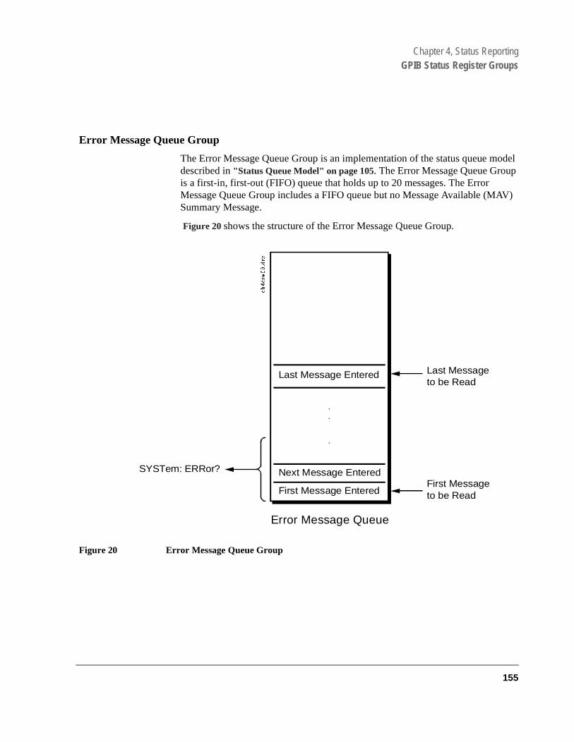
Chapter 4, Status ReportingGPIB Status Register Groups
Error Message Queue Group
The Error Message Queue Group is an implementation of the status queue model described in "Status Queue Model" on page 105. The Error Message Queue Group is a first-in, first-out (FIFO) queue that holds up to 20 messages. The Error Message Queue Group includes a FIFO queue but no Message Available (MAV) Summary Message.
Figure 20 shows the structure of the Error Message Queue Group.
Figure 20 Error Message Queue Group
Last Message Entered
Next Message Entered
First Message Entered
Last Messageto be Read
First Messageto be Read
SYSTem: ERRor?
Error Message Queue
155

Chapter 4, Status ReportingGPIB Status Register Groups
Accessing the Error Message Queue
A message appears in the Error Message Queue any time bit 2, 3, 4, or 5 of the Standard Event Status register is asserted. Each message consists of a signed error number, followed by a comma separator, followed by an error description string in double quotes. The maximum length of the error description string is 255 characters. If more than 20 messages are in the queue and another error occurs, the last message is replaced with the message, -350,"Queue overflow". If no messages are in the queue the message, +0,"No error" is returned. Reading a message removes it from the queue. The Error Message Queue is accessed using the SYSTem command. Returned information is read into a numeric variable followed by a string variable.
Reading the Error Message Queue
Syntax
SYSTem:ERRor?
Example
OUTPUT 714;"SYST:ERR?"ENTER 714;Error_num,Error_msg$
Example IBASIC program
10 INTEGER Error_num20 DIM Error_msg$ [255] 30 OUTPUT 714;"SYST:ERR?"40 ENTER 714;Error_num,Error_msg$50 PRINT Error_num;Error_msg$60 END
Example response
-113 “Undefined header”
156
S:\agilent\e8285\USRGUIDE\BOOK\CHAPTERS\hpibstat.fb

Chapter 4, Status ReportingGPIB Status Register Groups
et’s
tus
Hardware 1 Status Register Group
The Hardware 1 Status Register Group contains information about the Test Shardware, and the SMB for the Communicate Status Register Group.
The Status Byte Register summary message associated with the Hardware 1Status Register Group is bit zero.
Figure 21 shows the structure and STATus commands for the Hardware 1 StaRegister Group.
Table 13 shows the Hardware 1 Status Register Group Condition Register bitassignments.
157

Chapter 4, Status ReportingGPIB Status Register Groups
Figure 21 Hardware 1 Status Register Group
0
:STATus: HARDware1: ENABle?<integer>
:STATus: HARDware1: EVENt ?
:STATus: HARDware1:PTRansition
:NTRansition
?<integer>
?<integer>
:STATus: HARDware1: CONDition ?
Summary Message Bit
ConditionRegister
TransitionFilter Registers
EventRegister
EnableRegister
1
2
3
4
5
6
7
8
9
10
11
12
13
14
Log
ical
OR
15ch4drw13.drw
(to bit 0 of StatusByte Register)
158
S:\agilent\e8285\USRGUIDE\BOOK\CHAPTERS\hpibstat.fb

Chapter 4, Status ReportingGPIB Status Register Groups
Table 13 Hardware 1 Status Register Group Bit Assignments
Bit Number
Is Condition Register
Implemented? Condition/Event Comment
15 Unused in the Test Set Defined by SCPI Version 1994.0
14 NO Radio Interface Board interrupt 2 tripped
Not used. Hardware not present in the E8285.
NO Radio Interface Board interrupt 1 tripped
Not used. Hardware not present in the E8285.
12 YES Signaling Decoder Measurement Results Available
11 YES Signaling Decoder Input Level Too Low
10 YES Signaling Decoder is Measuring
9 YES Signaling Decoder is Armed
8 YES Signaling Encoder Sending Auxiliary Information
If the Signaling Mode selected has two information fields, such as the AMPS Filler and Message fields, and both fields are being sent, this bit will be set.
7 YES Signaling Encoder Sending Information
If the Signaling Mode selected has only one information field and the field is being sent, this bit will be set high. If the Signaling Mode selected has two information fields, such as the AMPS Filler and Message fields, and only one field is being sent, this bit will be set high.This bit is not active if the Signaling Encoder Mode is set to Function Generator
6 YES Communicate Status Register Group SMB
5 NO Measurement Limits exceeded This bit is set high if the measurement’s high or low limit is exceeded
159

Chapter 4, Status ReportingGPIB Status Register Groups
Accessing the Hardware Status Register #1 Group Registers
The following sections show the syntax and give programming examples, using the HP® BASIC programming language, for the STATus commands used to access the Hardware Status Register #1 Group registers.
Reading the Condition Register
Syntax
STATus:HARDware1:CONDition?
Example
OUTPUT 714;”STAT:HARD1:COND?”ENTER 714;Register_value
4 YES Power-up Self Test Failed
3 YES Overpower Protection Tripped
2 YES CDMA_1 Status Register Group SMB
1 YES External Mike Keyed Not used. Hardware not present in the E8285.
0 YES Battery Voltage Low
Table 13 Hardware 1 Status Register Group Bit Assignments (Continued)
Bit Number
Is Condition Register
Implemented? Condition/Event Comment
160
S:\agilent\e8285\USRGUIDE\BOOK\CHAPTERS\hpibstat.fb

Chapter 4, Status ReportingGPIB Status Register Groups
Reading the Transition Filters
Syntax
STATus:HARDware1:PTRansition?STATus:HARDware1:NTRansition?
Example
OUTPUT 714;”STAT:HARD1:PTR?”ENTER 714;Register_value
Writing the Transition Filters
Syntax
STATus:HARDware1:PTRansition <integer>STATus:HARDware1:NTRansition <integer>
Example
OUTPUT 714;”STAT:HARD1:PTR 256”
161
Chapter 4, Status ReportingGPIB Status Register Groups
Reading the Event Register
Syntax
STATus:HARDware1:EVENt?
Example
OUTPUT 714;”STAT:HARD1:EVEN?”ENTER 714;Register_value
Clearing the Event Register
The EVENT register is cleared whenever it is queried or whenever the Common Command *CLS is sent to the Test Set.
Reading the Enable Register
Syntax
STATus:HARDware1:ENABle?
Example
OUTPUT 714;”STAT:HARD1:ENAB?”ENTER 714;Register_value
Writing the Enable Register
Syntax
STATus:HARDware1:ENABle <integer>
Example
OUTPUT 714;”STAT:HARD1:ENAB 256”
Clearing the Enable Register
The ENABLE register is cleared by writing to it with an integer value of zero.
162
S:\agilent\e8285\USRGUIDE\BOOK\CHAPTERS\hpibstat.fb

Chapter 4, Status ReportingGPIB Status Register Groups
Set’s
tus
Hardware 2 Status Register Group
The Hardware Status Register #2 Group contains information about the Testhardware.
The Status Byte Register summary message associated with the Hardware 2Status Register Group is bit one.
Figure 22 shows the structure and STATus commands for the Hardware 2 StaRegister Group.
Table 14 shows the Hardware 2 Status Register Group Condition Register bitassignments.
163
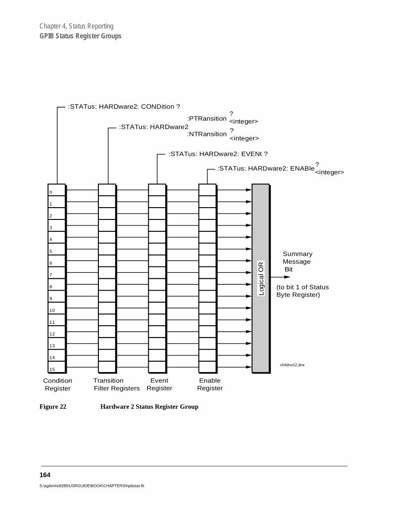
Chapter 4, Status ReportingGPIB Status Register Groups
Figure 22 Hardware 2 Status Register Group
0
:STATus: HARDware2: ENABle?<integer>
:STATus: HARDware2: EVENt ?
:STATus: HARDware2:PTRansition
:NTRansition
?<integer>
?<integer>
:STATus: HARDware2: CONDition ?
SummaryMessage Bit
ConditionRegister
TransitionFilter Registers
EventRegister
EnableRegister
1
2
3
4
5
6
7
8
9
10
11
12
13
14
Log
ica
l OR
15ch4drw12.drw
(to bit 1 of StatusByte Register)
164
S:\agilent\e8285\USRGUIDE\BOOK\CHAPTERS\hpibstat.fb

Chapter 4, Status ReportingGPIB Status Register Groups
Table 14 Hardware 2 Status Register Group Bit Assignments
Bit Number
Is Condition Register
Implemented? Condition/Event Comment
15 Not Used (Always 0) Defined by SCPI Version 1994.0
14 YES Pending DSP Measurement Interval
13 Unused in the Test Set
12 YES Reference Out-of-Lock
11 YES Pending ACP Bandwidth Inconsistent ACP Channel Bandwidth and Resolution Bandwidth
10 YES Pending ACP Frequency ACP Channel Bandwidth or Channel Offset Too Wide
9 YES Pending Variable Frequency Notch Frequency
AFGen1 Frequency Exceeds Variable Frequency Notch Filter Range
8 YES Voltage Out-of-Range Requested Audio Voltage Too Large for AFGen2
7 YES FM Out of Band Requested FM Deviation Too Large for RF Generator Frequency
6 YES Simultaneous AM/FM Simultaneous AM and FM Modulation not allowed.
5 YES Audio Ranging Error Audio Input Level Autoranging Error
4 YES Range Down Set RF Input Level Autoranging Error
3 YES Range Up Set RF Input Frequency Autotuning Error
2 YES Pending RF Frequency RF Gen/RF Anal/RF Offset frequency combination not possible. (RF GenTune Freq) - (RF Anal Tune Freq) not equal to (RF Offset Freq)
1 YES Pending RF Source Level RF generator amplitude level too high for selected output port
0 YES Pending RF Analyzer Level Spectrum analyzer reference level too high or low for selected input port
165

Chapter 4, Status ReportingGPIB Status Register Groups
Accessing the Hardware Status Register #2 Group Registers
The following sections show the syntax and give programming examples, using the HP® BASIC programming language, for the STATus commands used to access the Hardware 2 Status Register Group registers.
Reading the Condition Register
Syntax
STATus:HARDware2:CONDition?
Example
OUTPUT 714;”STAT:HARD2:COND?”ENTER 714;Register_value
Reading the Transition Filters
Syntax
STATus:HARDware2:PTRansition?STATus:HARDware2:NTRansition?
Example
OUTPUT 714;”STAT:HARD2:PTR?”ENTER 714;Register_value
Writing the Transition Filters
Syntax
STATus:HARDware2:PTRansition <integer>STATus:HARDware2:NTRansition <integer>
Example
OUTPUT 714;”STAT:HARD2:PTR 256”
166
S:\agilent\e8285\USRGUIDE\BOOK\CHAPTERS\hpibstat.fb

Chapter 4, Status ReportingGPIB Status Register Groups
Reading the Event Register
Syntax
STATus:HARDware2:EVENt?
Example
OUTPUT 714;”STAT:HARD2:EVEN?”ENTER 714;Register_value
Clearing the Event Register
The EVENT register is cleared whenever it is queried or whenever the Common Command *CLS is sent to the Test Set.
Reading the Enable Register
Syntax
STATus:HARDware2:ENABle?
Example
OUTPUT 714;”STAT:HARD2:ENAB?”ENTER 714;Register_value
Writing the Enable Register
Syntax
STATus:HARDware2:ENABle <integer>
Example
OUTPUT 714;”STAT:HARD2:ENAB 256”
Clearing the Enable Register
The ENABLE register is cleared by writing to it with an integer value of zero.
167

Chapter 4, Status ReportingGPIB Status Register Groups
Measuring Status Register Group
The Measuring Status Register Group contains information about measurements performed by the Test Set.
The Status Byte Register summary message associated with the Measuring Status Register Group is bit seven. The Measuring Status Register SMB must be enabled in the Operation Status Register Group before any of the events or conditions can be reported through the Status Byte Register.
Figure 23 shows the structure and STATus commands for the Measuring Status Register Group.
Table 15 shows the Measuring Status Register Group bit assignments.
168
S:\agilent\e8285\USRGUIDE\BOOK\CHAPTERS\hpibstat.fb

Chapter 4, Status ReportingGPIB Status Register Groups
Figure 23 Measuring Status Register Group
169

Chapter 4, Status ReportingGPIB Status Register Groups
Table 15 Measuring Status Register Group Bit Assignments
Bit Number Is Condition
Register Implemented?
Condition/Event Comment
15 Not Used (Always 0) Defined by SCPI Version 1994.0
14 Unused in the Test Set
13 Unused in the Test Set
12 Unused in the Test Set
11 Unused in the Test Set
10 Unused in the Test Set
9 Unused in the Test Set
8 Unused in the Test Set
7 Unused in the Test Set
6 Unused in the Test Set
5 Unused in the Test Set
4 Unused in the Test Set
3 Unused in the Test Set
2 YES Gated Power Test Running
1 YES Open Loop Time Response Test Running
0 YES FER Test Running
170
S:\agilent\e8285\USRGUIDE\BOOK\CHAPTERS\hpibstat.fb

Chapter 4, Status ReportingGPIB Status Register Groups
Accessing the Measuring Status Register Group Registers
The following sections show the syntax and give programming examples, using the HP® BASIC programming language, for the STATus commands used to access the Measuring Status Register Group registers.
Reading the Condition Register
Syntax
STATus:MEASuring:CONDition?
Example
OUTPUT 714;”STAT:MEAS:COND?”ENTER 714;Register_value
Reading the Transition Filters
Syntax
STATus:MEASuring:PTRansition?STATus:MEASuring:NTRansition?
Example
OUTPUT 714;”STAT:MEAS:PTR?”ENTER 714;Register_value
Writing the Transition Filters
Syntax
STATus:MEASuring:PTRansition <integer>STATus:MEASuring:NTRansition <integer>
Example
OUTPUT 714;”STAT:MEAS:PTR 256”
171
Chapter 4, Status ReportingGPIB Status Register Groups
Reading the Event Register Syntax
STATus:MEASuring:EVENt?
Example
OUTPUT 714;”STAT:MEAS:EVEN?”ENTER 714;Register_value
Clearing the Event Register
The EVENT register is cleared whenever it is queried or whenever the Common Command *CLS is sent to the Test Set.
Reading the Enable Register
Syntax
STATus:MEASuring:ENABle?
Example
OUTPUT 714;”STAT:MEAS:ENAB?”ENTER 714;Register_value
Writing the Enable Register
Syntax
STATus:MEASuring:ENABle <integer>
Example
OUTPUT 714;”STAT:MEAS:ENAB 256”
Clearing the Enable Register
The ENABLE register is cleared by writing to it with an integer value of zero.
172
S:\agilent\e8285\USRGUIDE\BOOK\CHAPTERS\hpibstat.fb
Chapter 4, Status ReportingGPIB Status Register Groups
Open Loop Time Response Status Register Group
The Open Loop Time Response Status Register Group monitors conditions and events related to the CDMA Open Loop Time Response measurement.
Figure 24 shows the structure and STATus commands for the Open Loop Time Response Status Register Group.
Table 16 shows the Open Loop Time Response Status Register Group bit assignments.
173

Chapter 4, Status ReportingGPIB Status Register Groups
Figure 24 Open Loop Time Response Status Register Group
174
S:\agilent\e8285\USRGUIDE\BOOK\CHAPTERS\hpibstat.fb

Chapter 4, Status ReportingGPIB Status Register Groups
Table 16 Open Loop Time Response Status Register Group Bit Assignments
Bit Number Is Condition
Register Implemented?
Condition/Event Comment
15 Not Used (Always 0) Defined by SCPI Version 1994.0
14 Unused in the Test Set
13 Unused in the Test Set
12 Unused in the Test Set
11 Unused in the Test Set
10 Unused in the Test Set
9 Unused in the Test Set
8 Unused in the Test Set
7 Unused in the Test Set
6 Unused in the Test Set
5 Unused in the Test Set
4 Unused in the Test Set
3 Unused in the Test Set
2 NO Open Loop Time Response Test Failed
1 NO Open Loop Time Response Test Passed
0 YES Open Loop Time Response Test Running
175

Chapter 4, Status ReportingGPIB Status Register Groups
Accessing the Open Loop Time Response Status Register Group Registers
The following sections show the syntax and give programming examples, using the HP® BASIC programming language, for the STATus commands used to access the OLTR Status Register Group registers.
Reading the Condition Register
Syntax
STATus:OLTR:CONDition?
Example
OUTPUT 714;”STAT:OLTR:COND?”ENTER 714;Register_value
Reading the Transition Filters
Syntax
STATus:OLTR:PTRansition?STATus:OLTR:NTRansition?
Example
OUTPUT 714;”STAT:OLTR:PTR?”ENTER 714;Register_value
Writing the Transition Filters
Syntax
STATus:OLTR:PTRansition <integer>STATus:OLTR:NTRansition <integer>
Example
OUTPUT 714;”STAT:OLTR:PTR 2”
176
S:\agilent\e8285\USRGUIDE\BOOK\CHAPTERS\hpibstat.fb

Chapter 4, Status ReportingGPIB Status Register Groups
Reading the Event Register Syntax
STATus:OLTR:EVENt?
Example
OUTPUT 714;”STAT:OLTR:EVEN?”ENTER 714;Register_value
Clearing the Event Register
The EVENT register is cleared whenever it is queried or whenever the Common Command *CLS is sent to the Test Set.
Reading the Enable Register
Syntax
STATus:OLTR:ENABle?
Example
OUTPUT 714;”STAT:OLTR:ENAB?”ENTER 714;Register_value
Writing the Enable Register
Syntax
STATus:OLTR:ENABle <integer>
Example
OUTPUT 714;”STAT:OLTR:ENAB 256”
Clearing the Enable Register
The ENABLE register is cleared by writing to it with an integer value of zero.
177

Chapter 4, Status ReportingGPIB Status Register Groups
or the
tatus
s
Operation Status Register Group
The Operation Status Register Group contains information about the state of the measurement systems in the Test Set, and summary message bits (SMB’s) fCDMA and Measuring Status Register Groups
The Status Byte Register summary message associated with the Operation SRegister Group is bit seven.
Figure 25 shows the structure and STATus commands for the Operation StatuRegister Group.
Table 15 shows the Operation Status Register Group bit assignments.
178
S:\agilent\e8285\USRGUIDE\BOOK\CHAPTERS\hpibstat.fb

Chapter 4, Status ReportingGPIB Status Register Groups
Figure 25 Operation Status Register Group
0
:STATus: OPERation: ENABle?<integer>
:STATus: OPERation: EVENt ?
:STATus: OPERation:PTRansition
:NTRansition
?<integer>
?<integer>
:STATus: OPERation: CONDition ?
SummaryMessageBit
ConditionRegister
TransitionFilter Registers
EventRegister
EnableRegister
1
2
3
4
5
6
7
8
9
10
11
12
13
14
Log
ical
OR
15
(to bit 7 of Status Byte Register)
ch4drw06.drw
179

Chapter 4, Status ReportingGPIB Status Register Groups
Table 17 Operation Status Register Group Bit Assignments
Bit Number
Is Condition Register
Implemented?Condition/Event Comment
15 Not Used (Always 0) Defined by SCPI Version 1994.0
14 YES IBASIC Program Running 1 = an IBASIC program is running on the built-in IBASIC controller
13 Unused in the Test Set
12 YES External Timebase in Use
11 YES IBASIC Status Register Group SMB
10 YES CDMA_2 Status Register Group SMB
9 YES Call Processing Status Register Group SMB
8 YES CDMA Status Register Group SMB
7 Unused in the Test Set
6 Unused in the Test Set
5 Unused in the Test Set
4 YES Measuring Status Register Group SMB
3 Unused in the Test Set
2 NO Ranging Error
1 Unused in the Test Set
0 YES Calibrating Status Register Group SMB
180
S:\agilent\e8285\USRGUIDE\BOOK\CHAPTERS\hpibstat.fb

Chapter 4, Status ReportingGPIB Status Register Groups
Accessing the Operation Status Register Group Registers
The following sections show the syntax and give programming examples, using the HP® BASIC programming language, for the STATus commands used to access the Operation Status Register Group registers.
Reading the Condition Register
Syntax
STATus:OPERation:CONDition?
Example
OUTPUT 714;”STAT:OPER:COND?”ENTER 714;Register_value
Reading the Transition Filters
Syntax
STATus:OPERation:PTRansition?STATus:OPERation:NTRansition?
Example
OUTPUT 714;”STAT:OPER:PTR?”ENTER 714;Register_value
Writing the Transition Filters
Syntax
STATus:OPERation:PTRansition <integer>STATus:OPERation:NTRansition <integer>
Example
OUTPUT 714;”STAT:OPER:PTR 256”
181

Chapter 4, Status ReportingGPIB Status Register Groups
Reading the Event Register
Syntax
STATus:OPERation:EVENt?
Example
OUTPUT 714;”STAT:OPER:EVEN?”ENTER 714;Register_value
Clearing the Event Register
The EVENT register is cleared whenever it is queried or whenever the Common Command *CLS is sent to the Test Set.
Reading the Enable Register
Syntax
STATus:OPERation:ENABle?
Example
OUTPUT 714;”STAT:OPER:ENAB?”ENTER 714;Register_value
Writing the Enable Register
Syntax
STATus:OPERation:ENABle <integer>
Example
OUTPUT 714;”STAT:OPER:ENAB 256”
Clearing the Enable Register
The ENABLE register is cleared by writing to it with an integer value of zero.
182
S:\agilent\e8285\USRGUIDE\BOOK\CHAPTERS\hpibstat.fb

Chapter 4, Status ReportingGPIB Status Register Groups
Output Queue Group
The Output Queue Group is a specific implementation of the status queue model described in "Status Queue Model" on page 105. When a command is sent to the Test Set that causes the Test Set to generate data, this data is buffered in the Output Queue until it is read by the controller or the Output Queue Group is cleared. The Output Queue Group includes a FIFO queue and a Message Available (MAV) Summary Message.
Figure 26 shows the structure of the Output Queue Group.
Figure 26 Output Queue Group
Last Data Byte Entered
Next Data Byte Entered
First Data Byte Entered
Last Data Byteto be Read
First Data Byteto be Read
Message Available ( MAV )(to bit 4 of Status Byte Register)
Queue Empty = "0"Queue Not - Empty = "1"
Output Queue
183

Chapter 4, Status ReportingGPIB Status Register Groups
Accessing the Output Queue
The availability of data from the Test Set is summarized in the MAV bit of the Status Byte Register. The MAV message is TRUE, logic 1, when there is data in the Output Queue and FALSE, logic 0, when it is empty. The Output Queue is read by sending a command, such as the HP® BASIC command ENTER, and waiting (if necessary) for data to become available. After data is read, subsequent bus messages will be processed.
Reading the Output Queue
Example
Enter 714;Output_data
184
S:\agilent\e8285\USRGUIDE\BOOK\CHAPTERS\hpibstat.fb

Chapter 4, Status ReportingGPIB Status Register Groups
Power Status Register Group
The Power Status Register Group contains information about power measurement calibration.
Figure 27 shows the structure and STATus commands for the Power Status Register Group.
Table 18 shows the Power Status Register Group bit assignments.
185
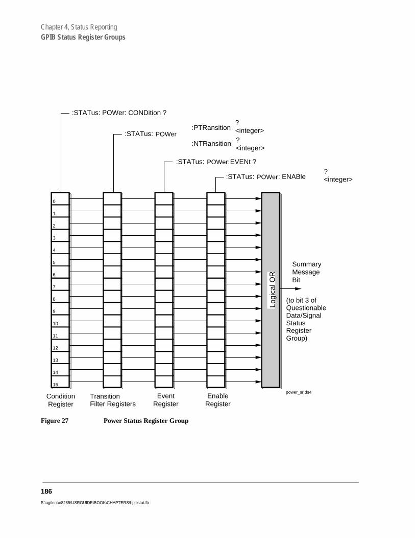
Chapter 4, Status ReportingGPIB Status Register Groups
Figure 27 Power Status Register Group
0
:STATus: POWer: ENABle?<integer>
:STATus: POWer:EVENt ?
:STATus: POWer:PTRansition
:NTRansition
?<integer>?<integer>
:STATus: POWer: CONDition ?
SummaryMessageBit
ConditionRegister
TransitionFilter Registers
EventRegister
EnableRegister
1
2
3
4
5
6
7
8
9
10
11
12
13
14
Logi
cal O
R
15
(to bit 3 ofQuestionableData/SignalStatusRegisterGroup)
power_sr.ds4
186
S:\agilent\e8285\USRGUIDE\BOOK\CHAPTERS\hpibstat.fb

Chapter 4, Status ReportingGPIB Status Register Groups
Table 18 Power Status Register Group Bit Assignments
Bit Number
Is Condition Register
Implemented?Condition/Event Comment
15 Not Used (Always 0) Defined by SCPI Version 1994.0
14 Unused in the Test Set
13 Unused in the Test Set
12 Unused in the Test Set
11 Unused in the Test Set
10 Unused in the Test Set
9 Unused in the Test Set
8 Unused in the Test Set
7 Unused in the Test Set
6 Unused in the Test Set
5 Unused in the Test Set
4 Unused in the Test Set
3 Unused in the Test Set
2 YES Channel Power Uncalibrated. Above Temperature
The temperature has drifted by more than 10 °C above the temperature at calibration.
1 YES Channel Power Uncalibrated. Below Temperature
The temperature has drifted by more than 10 °C below the temperature at calibration.
0 YES Channel Power Uncalibrated. Frequency Range
The power measurement has not been calibrated at the analyzer’s current frequency.
187

Chapter 4, Status ReportingGPIB Status Register Groups
Accessing the Power Status Register Group Registers
The following sections show the syntax and give programming examples, using the HP® BASIC programming language, for the STATus commands used to access the Operation Status Register Group registers.
Reading the Condition Register
Syntax
STATus:POWer:CONDition?
Example
OUTPUT 714;”STAT:POW:COND?”ENTER 714;Register_value
Reading the Transition Filters
Syntax
STATus:POWer:PTRansition?STATus:POWer:NTRansition?
Example
OUTPUT 714;”STAT:POW:PTR?”ENTER 714;Register_value
Writing the Transition Filters
Syntax
STATus:POWer:PTRansition <integer>STATus:POWer:NTRansition <integer>
Example
OUTPUT 714;”STAT:POW:PTR 256”
188
S:\agilent\e8285\USRGUIDE\BOOK\CHAPTERS\hpibstat.fb

Chapter 4, Status ReportingGPIB Status Register Groups
Reading the Event Register
Syntax
STATus:POWer:EVENt?
Example
OUTPUT 714;”STAT:POW:EVEN?”ENTER 714;Register_value
Clearing the Event Register
The EVENT register is cleared whenever it is queried or whenever the Common Command *CLS is sent to the Test Set.
Reading the Enable Register
Syntax
STATus:POWer:ENABle?
Example
OUTPUT 714;”STAT:POW:ENAB?”ENTER 714;Register_value
Writing the Enable Register
Syntax
STATus:POWer:ENABle <integer>
Example
OUTPUT 714;”STAT:POW:ENAB 256”
Clearing the Enable Register
The ENABLE register is cleared by writing to it with an integer value of zero.
189

Chapter 4, Status ReportingGPIB Status Register Groups
e
le
ata/
ster
Questionable Data/Signal Register Group
The Questionable Data/Signal Register Group contains information about the quality of the Test Set’s output and measurement data, and the SMB from thCalibration Status Register Group.
The Status Byte Register summary message associated with the QuestionabData/Signal Register Group is bit three.
Figure 28 shows the structure and STATus commands for the Questionable DSignal Register Group.
Table 19 shows the Questionable Data/Signal Register Group Condition Regibit assignments.
190
S:\agilent\e8285\USRGUIDE\BOOK\CHAPTERS\hpibstat.fb

Chapter 4, Status ReportingGPIB Status Register Groups
Figure 28 Questionable Data/Signal Register Group
0
:STATus: QUEStionable: ENABle?<integer>
:STATus: QUEStionable: EVENt ?
:STATus: QUEStionable:PTRansition
:NTRansition
?<integer>
?<integer>
:STATus: QUEStionable: CONDition ?
SummaryMessage Bit
ConditionRegister
TransitionFilter Registers
EventRegister
EnableRegister
1
2
3
4
5
6
7
8
9
10
11
12
13
14
Log
ical
OR
15 ch4drw10.drw
(to bit 3 of StatusByte Register)
191

Chapter 4, Status ReportingGPIB Status Register Groups
Accessing the Questionable Data/Signal Register Group Registers
Table 19 Questionable Data/Signal Register Group Bit Assignments
Bit Number
Is Condition Register
Implemented? Condition/Event Comment
15 Not Used (Always 0) Defined by SCPI Version 1994.0
14 Unused in the Test Set
13 YES Indeterminate Measurement Result
12 Unused in the Test Set
11 Unused in the Test Set
10 Unused in the Test Set
9 Unused in the Test Set
8 YES Calibration Register Group SMB
7 Unused in the Test Set
6 Unused in the Test Set
5 Unused in the Test Set
4 Unused in the Test Set
3 YES Power Status Register Group SMB
2 Unused in the Test Set
1 Unused in the Test Set
0 Unused in the Test Set
192
S:\agilent\e8285\USRGUIDE\BOOK\CHAPTERS\hpibstat.fb

Chapter 4, Status ReportingGPIB Status Register Groups
The following sections show the syntax and give programming examples, using the HP® BASIC programming language, for the STATus commands used to access the Questionable Data/Signal Register Group registers.
Reading the Condition Register
Syntax
STATus:QUEStionable:CONDition?
Example
OUTPUT 714;”STAT:QUES:COND?”ENTER 714;Register_value
Reading the Transition Filters
Syntax
STATus:QUEStionable:PTRansition?STATus:QUEStionable:NTRansition?
Example
OUTPUT 714;”STAT:QUES:PTR?”ENTER 714;Register_value
Writing the Transition Filters
Syntax
STATus:QUEStionable:PTRansition <integer>STATus:QUEStionable:NTRansition <integer>
Example
OUTPUT 714;”STAT:QUES:PTR 256”
193

Chapter 4, Status ReportingGPIB Status Register Groups
Reading the Event Register
Syntax
STATus:QUEStionable:EVENt?
Example
OUTPUT 714;”STAT:QUES:EVEN?”ENTER 714;Register_value
Clearing the Event Register The EVENT register is cleared whenever it is queried or whenever the Common Command *CLS is sent to the Test Set.
Reading the Enable Register Syntax
STATus:QUEStionable:ENABle?
Example
OUTPUT 714;”STAT:QUES:ENAB?”ENTER 714;Register_value
Writing the Enable Register
Syntax
STATus:QUEStionable:ENABle <integer>
Example
OUTPUT 714;”STAT:QUES:ENAB 256”
Clearing the Enable Register
The ENABLE register is cleared by writing to it with an integer value of zero.
194
S:\agilent\e8285\USRGUIDE\BOOK\CHAPTERS\hpibstat.fb

Chapter 4, Status ReportingGPIB Status Register Groups
Serial 1 Status Register Group
The Serial 1 Status Register Group contains information about SBRC (Serial Bus Receiver Chip) communication errors which occur either at power up or when an GPIB *TST? command is issued.
The Status Byte Register summary message associated with the Serial 1 Status Register Group is bit zero. The Serial 1 Status Register Group SMB in the Communicate Status Register Group and the Communicate Status Register Group SMB in the Hardware 1 Status Register Group must be enabled before any of the following events or conditions can be reported through the Status Byte Register.
Figure 29 on page 196 shows the structure and STATus commands for the Serial 1 Status Register Group.
Table 15 shows the Serial 1 Status Register Group Condition Register bit assignments.
195

Chapter 4, Status ReportingGPIB Status Register Groups
Figure 29 Serial 1 Status Register Group
196
S:\agilent\e8285\USRGUIDE\BOOK\CHAPTERS\hpibstat.fb

Chapter 4, Status ReportingGPIB Status Register Groups
Table 20 Serial 1 Status Register Group Bit Assignments
Bit Number Is Condition
Register Implemented?
Condition/Event Comment
15 Not Used (Always 0) Defined by SCPI Version 1994.0
14 Unused in the Test Set
13 Unused in the Test Set
12 Unused in the Test Set
11 Unused in the Test Set
10 Unused in the Test Set
9 Unused in the Test Set
8 NO LO/IF Communication Error
7 NO CDMA Reference Communication Error
6 NO Modulation Distribution Communication Error
5 NO Audio 2 Communication Error
4 NO Audio1 Communication Error
3 NO Receiver Communication Error
2 NO Spectrum Analyzer Communication Error
1 NO Receiver Synthesizer Communication Error
0 Unused in the Test Set
197

Chapter 4, Status ReportingGPIB Status Register Groups
Accessing the Serial 1 Status Register Group Registers
The following sections show the syntax and give programming examples, using the HP® BASIC programming language, for the STATus commands used to access the Serial 1 Status Register Group registers.
Reading the Condition Register
Syntax
STATus:SER1:CONDition?
Example
OUTPUT 714;”STAT:OPER:COND?”ENTER 714;Register_value
Reading the Transition Filters
Syntax
STATus:SER1:PTRansition?STATus:SER1:NTRansition?
Example
OUTPUT 714;”STAT:OPER:PTR?”ENTER 714;Register_value
Writing the Transition Filters
Syntax
STATus:SER1:PTRansition <integer>STATus:SER1:NTRansition <integer>
Example
OUTPUT 714;”STAT:OPER:PTR 256”
198
S:\agilent\e8285\USRGUIDE\BOOK\CHAPTERS\hpibstat.fb

Chapter 4, Status ReportingGPIB Status Register Groups
Reading the Event Register
Syntax
STATus:SER1:EVENt?
Example
OUTPUT 714;”STAT:OPER:EVEN?”ENTER 714;Register_value
Clearing the Event Register
The EVENT register is cleared whenever it is queried or whenever the Common Command *CLS is sent to the Test Set.
Reading the Enable Register
Syntax
STATus:SER1:ENABle?
Example
OUTPUT 714;”STAT:OPER:ENAB?”ENTER 714;Register_value
Writing the Enable Register
Syntax
STATus:SER1:ENABle <integer>
Example
OUTPUT 714;”STAT:OPER:ENAB 256”
Clearing the Enable Register
The ENABLE register is cleared by writing to it with an integer value of zero.
199

Chapter 4, Status ReportingGPIB Status Register Groups
Serial 2 Status Register Group
The Serial 2 Status Register Group contains information about SBRC (Serial Bus Receiver Chip) communication errors which occur either at power up or when an GPIB *TST? command is issued.
The Status Byte Register summary message associated with the Serial 2 Status Register Group is bit zero. The Serial 2 Status Register Group SMB in the Communicate Status Register Group and the Communicate Status Register Group SMB in the Hardware 1 Status Register Group must be enabled before any of the following events or conditions can be reported through the Status Byte Register.
Figure 30 on page 201 shows the structure and STATus commands for the Serial 2 Status Register Group.
Table 15 shows the Serial 2 Status Register Group Condition Register bit assignments.
200
S:\agilent\e8285\USRGUIDE\BOOK\CHAPTERS\hpibstat.fb

Chapter 4, Status ReportingGPIB Status Register Groups
Figure 30 Serial 2 Status Register Group
201

Chapter 4, Status ReportingGPIB Status Register Groups
Table 21 Serial 2 Status Register Group Bit Assignments
Bit Number
Is Condition Register
Implemented?Condition/Event Comment
15 Not Used (Always 0) Defined by SCPI Version 1994.0
14 Unused in the Test Set
13 Unused in the Test Set
12 Unused in the Test Set
11 Unused in the Test Set
10 NO Reserved
9 Unused in the Test Set
8 Unused in the Test Set
7 Unused in the Test Set
6 NO Cell Site Analog Communication Error
5 NO IQ Modulator Communication Error
4 NO Input Section 2 Communication Error
3 NO Input Section 1 Communication Error
2 NO Output Communication Error
1 NO RF Source Communication Error
0 NO Reference Communication Error
202
S:\agilent\e8285\USRGUIDE\BOOK\CHAPTERS\hpibstat.fb

Chapter 4, Status ReportingGPIB Status Register Groups
Accessing the Serial 2 Status Register Group Registers
The following sections show the syntax and give programming examples, using the HP® BASIC programming language, for the STATus commands used to access the Serial 2 Status Register Group registers.
Reading the Condition Register
Syntax
STATus:SER2:CONDition?
Example
OUTPUT 714;”STAT:OPER:COND?”ENTER 714;Register_value
Reading the Transition Filters
Syntax
STATus:SER2:PTRansition?STATus:SER2:NTRansition?
Example
OUTPUT 714;”STAT:OPER:PTR?”ENTER 714;Register_value
Writing the Transition Filters
Syntax
STATus:SER2:PTRansition <integer>STATus:SER2:NTRansition <integer>
Example
OUTPUT 714;”STAT:OPER:PTR 256”
203

Chapter 4, Status ReportingGPIB Status Register Groups
Reading the Event Register
Syntax
STATus:SER2:EVENt?
Example
OUTPUT 714;”STAT:OPER:EVEN?”ENTER 714;Register_value
Clearing the Event Register
The EVENT register is cleared whenever it is queried or whenever the Common Command *CLS is sent to the Test Set.
Reading the Enable Register
Syntax
STATus:SER2:ENABle?
Example
OUTPUT 714;”STAT:OPER:ENAB?”ENTER 714;Register_value
Writing the Enable Register
Syntax
STATus:SER2:ENABle <integer>
Example
OUTPUT 714;”STAT:OPER:ENAB 256”
Clearing the Enable Register
The ENABLE register is cleared by writing to it with an integer value of zero.
204
S:\agilent\e8285\USRGUIDE\BOOK\CHAPTERS\hpibstat.fb

Chapter 4, Status ReportingGPIB Status Register Groups
Standard Event Status Register Group
The Standard Event Status Register Group is a specific implementation of the status register model described in the Status Register Structure Overview section. The conditions monitored by the Standard Event Status Register Group are defined by the IEEE 488.2-1987 Standard.
Figure 31 shows the structure and IEEE 488.2 Common Commands used to access the Standard Event Status Register Group.
Figure 31 Standard Event Status Register Group
*ESE <integer>*ESE?
*ESR?
Event Summary Bit (ESB)(to bit 5 of Status Byte Register)
EventRegister
EnableRegister
Log
ica
l OR
0
1
2
3
4
5
6
7
8
9
10
11
12
13
14
15ch4drw7.drw
205

Chapter 4, Status ReportingGPIB Status Register Groups
Table 22 Standard Event Status Register Group Bit Assignments
Bit Number
Is Condition Register
Implemented?Condition/Event Comment
15 Not Used (Always 0) Defined by SCPI Version 1994.0
14 Unused in the Test Set
13 Unused in the Test Set
12 Unused in the Test Set
11 Unused in the Test Set
10 Unused in the Test Set
9 Unused in the Test Set
8 Unused in the Test Set
7 NO Power On Request 1 = Test Set’s power supply has been turned off and then on since the last time this register was read.
6 NO User Request Not implemented in Test Set.
5 NO Command Error 1 = The Test Set detected an error while trying to process a command. The following events cause a command error:
a An IEEE 488.2 syntax error. This means that the Test Set received a message that did not follow the syntax defined by the Standard.
b A semantic error. For exam-ple, the Test Set received anincorrectly spelled command.
c The Test Set received a Group Execute Trigger (GET) inside a program message.
206
S:\agilent\e8285\USRGUIDE\BOOK\CHAPTERS\hpibstat.fb

Chapter 4, Status ReportingGPIB Status Register Groups
4 NO Execution Error 1 = The Test Set detected an error while trying to execute a command. The following events cause an execution error:
a A <PROGRAM DATA> ele-ment received in a command is outside the legal range for the Test Set or is inconsistent with the operation of the Test Set.
b The Test Set could not exe-cute a valid command due to some Test Set hardware/firm-ware condition.
3 NO Device Dependent Error 1 = A Test Set dependent error has occurred. This means that some Test Set operation did not execute properly due to some internal condition, such as over range. This bit indicates that the error was not a command, query or execution error.
2 NO Query Error 1 = An error has occurred while trying to read the Test Set’s Output Queue. The following events cause a query error:
a An attempt is being made to read data from the Output Queue when no data is present or pending.
b Data in the Output Queue has been lost. An example of this would be Output Queue over-flow.
1 NO Request Control 1 = The Test Set is requesting permission to become the active controller on the GPIB bus.
Table 22 Standard Event Status Register Group Bit Assignments (Continued)
Bit Number
Is Condition Register
Implemented?Condition/Event Comment
207

Chapter 4, Status ReportingGPIB Status Register Groups
Accessing the Standard Event Status Register Group Registers
The following sections show the syntax and give programming examples, using the HP® BASIC programming language, for the Common Commands used to access the Standard Event Status Register Group registers.
Reading the Event Register
Syntax
*ESR?
Example
OUTPUT 714;”*ESR?”ENTER 714;Register_value
Clearing the Event Register
The EVENT register is cleared whenever it is queried or whenever the *CLS Common Command is sent to the Test Set.
0 NO Operation Complete 1 = The Test Set has completed all selected pending operations and is ready to accept new commands. This bit is only generated in response to the *OPC IEEE 488.2 Common Command.
Table 22 Standard Event Status Register Group Bit Assignments (Continued)
Bit Number
Is Condition Register
Implemented?Condition/Event Comment
208
S:\agilent\e8285\USRGUIDE\BOOK\CHAPTERS\hpibstat.fb

Chapter 4, Status ReportingGPIB Status Register Groups
Reading the Enable Register
Syntax
*ESE?
Example
OUTPUT 714;”*ESE?”ENTER 714;Register_value
10 INTEGER Std_evn_enab_rg20 OUTPUT 714;”ESE?”30 ENTER 714;Std_evn_enab_rg40 PRINT Std_evn_enab_rg50 END
Writing the Enable Register
Syntax
*ESE <integer>
Example
OUTPUT 714;”*ESE 255”
Clearing the Enable Register
The ENABLE register is cleared by writing to it with an integer value of zero.
209
Chapter 4, Status ReportingGPIB Status Register Groups
Status Byte/Service Request Enable Register
The Status Byte Register is an 8-bit register that summarizes the Summary Message Bits from the status register groups and the Output Queue. The Status Byte Register can be used to send a Service Request (SRQ) to the controller.
Service request enabling allows the application programmer to select which Summary Messages in the Status Byte Register may cause a service request.
The Service Request Enable Register, illustrated in figure 32 , is an 8-bit register that enables corresponding Summary Messages in the Status Byte Register.
Table 23 details the Status Byte Register bit assignments.
210
S:\agilent\e8285\USRGUIDE\BOOK\CHAPTERS\hpibstat.fb

Chapter 4, Status ReportingGPIB Status Register Groups
Figure 32 Status Byte/Service Request Enable Register
- - - Summary Message Bits - - -
LogicalOR
Service RequestEnable Register*SRE <interger>*SRE?
&&
&
Status Byte Registe
1 07 5 4 3 2
&&
&
read by *STB?
read by Serial PollSRQ
ch4drw15.drw
7 6 ESB MAV 3 2 1 0
RQS
MSS
ServiceRequest
Generation
&
Status Byte Register
211

Chapter 4, Status ReportingGPIB Status Register Groups
Table 23 Status Byte Register Bit Assignments
Bit Number
Defined by Data Structures Summarized through this Status Byte Bit
Comments
7 SCPI *Operation Status Register Group*CDMA Status Register Group*Measuring Status Register Group
TRUE = One or more enabled event bits in the associated status registers is TRUE.
6 IEEE 488.2 None Request Service (RQS) when read by serial poll OR Master Summary Status message when read by *STB? command. This bit cannot be masked
5 IEEE 488.2 *Standard Event Status Register Group
TRUE = One or more enabled event bits in the associated status registers is TRUE.
4 IEEE 488.2 *Output Queue Group Message Available (MAV) Summary Message
TRUE = One or more enabled event bits in the associated status registers is TRUE.
3 SCPI *Questionable Data/Signal Register Group*Calibration Status Register group
TRUE = One or more enabled event bits in the associated status registers is TRUE.
2 Unused in the Test Set
1 Test Set *Hardware #2 Status Register Group Summary Message
TRUE = One or more enabled event bits in the associated status registers is TRUE.
0 Test Set *Hardware #1 Status Register*Communicate Status Register Group*Serial 1 Status Register Group*Serial 2 Status Register Group
TRUE = One or more enabled event bits in the associated status registers is TRUE.
212
S:\agilent\e8285\USRGUIDE\BOOK\CHAPTERS\hpibstat.fb

Chapter 4, Status ReportingGPIB Status Register Groups
t 64). l to
8.2-l
ble,
Reading the Status Byte Register
Reading with a Serial Poll. The contents of the Status Byte Register can be read by a serial poll from the Active Controller in response to some device on the bus sending the Service Request (SRQ) message. When read with a serial poll, bit 6 in the Status Byte Register represents the Request Service (RQS) condition. Bit 6 is TRUE, logic 1, if the Test Set is sending the Service Request (SRQ) message and FALSE, logic 0, if it is not. Bits 0-5 and bit 7 are defined as shown in table 23 on page 212. When read by a serial poll the RQS bit is cleared (set to 0) so that the RQS message will be FALSE if the Test Set is polled again before a new reason for requesting service has occurred. Bits 0-5 and bit 7 are unaffected by a serial poll.
When read with the Serial Poll (SPOLL) command, bit 6 represents the RQS condition.
Reading with the *STB? Common Command. The contents of the Status Byte Register can be read by the application program using the *STB? Common Command. When read with the *STB? Common Command, bit 6 represents the Master Summary Status (MSS) message. The MSS message is the inclusive OR of the bitwise combination (excluding bit 6) of the Status Byte Register and the Service Request Enable Register. For a discussion of Summary Messages, see "Status Register Structure Overview" on page 101. Bit 6 is TRUE, logic 1, if the Test Set has at least one reason for requesting service and FALSE, logic 0, if it does not. Bits 0-5 and bit 7 are defined as shown in table 23 on page 212. When read by the *STB? Common Command, bits 0-5, bit 6, and bit 7 are unaffected
The *STB? Status Byte Query allows the programmer to determine the current contents (bit pattern) of the Status Byte Register and the Master Summary Status (MSS) message as a single element. The Test Set responds to the *STB? query by placing the binary-weighted decimal value of the Status Byte Register and the MSS message into the Output Queue. The response represents the sum of the binary-weighted values of the Status Byte Register’s bits 0-5 and 7 (weights 1,2,4,8,16,32 and 128 respectively) and the MSS summary message (weighThus, the response to *STB?, when considered as a binary value, is identicathe response to a serial poll except that the MSS message of 1 indicates that the Test Set has at least one reason for requesting service (Refer to the IEEE 481987 Standard for a complete description of the MSS message). The decimavalue of the bit pattern will be a positive integer in the range of 0 to 255. Theresponse data is obtained by reading the Output Queue into a numeric variainteger or real.
When read with the *STB? Common Command, bit 6 represents the Master Summary Status (MSS) message.
213

Chapter 4, Status ReportingGPIB Status Register Groups
An example of reading the Status Byte register using *STB? is shown below.
Example BASIC program
10 INTEGER Stat_byte_reg,Stat_byte,Mstr_sum_msg20 OUTPUT 714;”*STB?”30 ENTER 714;Stat_byte_reg40 Stat_byte=BINAND(Stat_byte_reg,191)50 PRINT Stat_byte60 Mstr_sum_msg=BINAND(Stat_byte_reg,64)70 PRINT Mstr_sum_msg80 END
Example response
320
Writing the Status Byte Register
The Status Byte Register is a read only register and is altered only when the state of the Summary Messages from the overlaying data structures are altered.
Clearing the Status Byte Register
The *CLS Common Command clears all Event Registers and Queues so that their corresponding Summary Messages are cleared. The Output Queue and its MAV Summary Message are an exception and are unaffected by the *CLS Common Command.
Reading the Service Request Enable Register
The Service Request Enable Register is read with the *SRE? Common Command. The *SRE? query allows the programmer to determine the current contents (bit pattern) of the Service Request Enable Register. The Test Set responds to the *SRE? query by placing the binary-weighted decimal value of the Service Request Enable Register bit pattern into the Output Queue. The decimal value of the bit pattern will be a positive integer in the range 0 to 255. The response data is obtained by reading the Output Queue into a numeric variable, integer or real.
Example BASIC program
10 INTEGER Srv_rqs_enab_rg20 OUTPUT 714;”*SRE?”30 ENTER 714;Srv_rqs_enab_rg40 PRINT Srv_rqs_enab_rg50 END
Example response
18
214
S:\agilent\e8285\USRGUIDE\BOOK\CHAPTERS\hpibstat.fb
Chapter 4, Status ReportingGPIB Status Register Groups
Writing the Service Request Enable Register
The Service Request Enable Register is written with the *SRE Common Command. The *SRE command sets the bit pattern (bits 0-5 and 7) of the Service Request Enable Register. The Service Request Enable Register allows the programmer to select which condition(s), as defined by bits 0-5 and 7 of the Status Byte Register, will generate a Service Request on the GPIB bus. The Test Set always ignores bit 6 (binary weight 64) of the bit pattern set by the *SRE command.
The bit pattern set by the *SRE command is determined by selecting the desired condition(s) from the Status Byte Register, setting the value of the bit position(s) to a logical one, setting the value of all non-selected bit positions to a logical zero, and sending the binary-weighted decimal equivalent of bits 0-5 and 7 after the *SRE command. For example, if the programmer wished to have the occurrence of a message available in the Output Queue (bit position 4 in the Status Byte Register) and the occurrence of a condition in the Hardware# 2 Status Register (bit position 1 in the Status Byte Register) to generate a Service Request on the GPIB bus, the binary-weighted decimal value of the bit pattern for the Service Request Enable Register would be determined as shown in table 24.
215
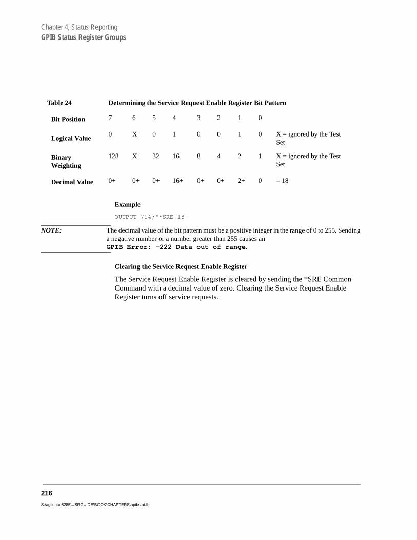
Chapter 4, Status ReportingGPIB Status Register Groups
Example
OUTPUT 714;"*SRE 18"
NOTE: The decimal value of the bit pattern must be a positive integer in the range of 0 to 255. Sendinga negative number or a number greater than 255 causes an GPIB Error: -222 Data out of range.
Clearing the Service Request Enable Register
The Service Request Enable Register is cleared by sending the *SRE Common Command with a decimal value of zero. Clearing the Service Request Enable Register turns off service requests.
Table 24 Determining the Service Request Enable Register Bit Pattern
Bit Position 7 6 5 4 3 2 1 0
Logical Value0 X 0 1 0 0 1 0 X = ignored by the Test
Set
Binary Weighting
128 X 32 16 8 4 2 1 X = ignored by the Test Set
Decimal Value 0+ 0+ 0+ 16+ 0+ 0+ 2+ 0 = 18
216
S:\agilent\e8285\USRGUIDE\BOOK\CHAPTERS\hpibstat.fb
Chapter 4, Status ReportingUsing Service Request (SRQ) Interrupts
Using Service Request (SRQ) Interrupts
The Test Set provides many status bits which can be read directly or used to generate SRQ interrupts. For example, the following status indicators have status bits (in addition to front panel annunciators):
• Transmitting• Registered• Page Sent• Access Probe• Connected• Softer Handoff• Hard Handoff
SRQ interrupts require more program code than requesting status at different time intervals (polling), but interrupts have the advantage of allowing the Call Processing Subsystem to operate at its maximum speed since processes within the subsystem are not constantly interrupted by commands on the GPIB.
See "Status Register Programming Considerations" in the Status Reporting chapter of the E8285A User’s Guide.
If your computer system or programming language does not support the SRQ feature of the GPIB, polling will be required.
217
Chapter 4, Status ReportingSetting up an SRQ Interrupt
Setting up an SRQ Interrupt
The Test Set provides many status bits which can be read directly or used to generate SRQ interrupts. For example, the following front panel annunciators have assigned status bits:
• Transmitting• Registering• Page Sent• Access Probe• Connected• Softer Handoff• Hard Handoff
Using SRQ interrupts requires more program code than requesting status at different time intervals (polling), but SRQ interrupts have the advantage of allowing the Call Processing Subsystem to operate at its maximum speed since processes within the subsystem are not constantly interrupted by commands on the GPIB.
218
S:\agilent\e8285\USRGUIDE\BOOK\CHAPTERS\hpibstat.fb

Chapter 4, Status ReportingSetting up an SRQ Interrupt
About this Procedure
Computer System
An HP® 9000 Series 300 running the HP® BASIC programming language was used to develop the following procedure and program example.
Description of Procedure
The following procedure provides example commands that will generate an SRQ Interrupt when the Connected bit, (bit 3 in the CDMA Status Register Group) indicates that a call has been dropped.
A complete "Example BASIC Program to Set Up and Service an SRQ Interrupt" on page 229 is provided after the SRQ interrupt procedure is described.
See "CDMA Status Register Group" on page 124 for detailed reference information about status reporting structure and CDMA status register group bit definitions.
Procedure Overview
For detailed step-by-step explanation see the page associated with the step.
1. "Decide which conditions will be used to generate an SRQ interrupt." on page 220.2. "Set up the CDMA Status Register Group Transition Filters." on page 222.3. "Enable the CDMA Status Register Group SMB." on page 223.4. "Enable the Operation Status Register Group SMB." on page 224.5. "Enable SRQ Generation." on page 225.6. "Define the program branch desired when an enabled interrupt occurs." on page
226.7. "Enable the Interrupt." on page 227.8. "Service the interrupt." on page 228.
219

Chapter 4, Status ReportingSetting up an SRQ Interrupt
1. Decide which conditions will be used to generate an SRQ interrupt.
For the following procedure and programming example, the CDMA Call Connected bit, (see "CDMA Status Register Group Bit Assignments" on page 126) will generate an SRQ interrupt when a a high-to-low transition occurs, indicating that a call ended or was dropped.
Refer to figure 33 below for a graphic summary of all of the Status Register Groups. Note that the CDMA Status Register Group summary message bit (SMB) does not report directly into the Status Byte Register Group. Instead, it is routed to the Operation Status Register Group. The following steps will show you how to set up each register group to allow propagation of bit-states to the Status Byte register, which is required before an SRQ interrupt can be generated.
220
S:\agilent\e8285\USRGUIDE\BOOK\CHAPTERS\hpibstat.fb

Chapter 4, Status ReportingSetting up an SRQ Interrupt
Figure 33 Test Set Data Structures
C TR EV EN
Log
ical
OR
C TR EV EN
Log
ical
OR
0L
ogic
al O
R
SMB 8 SMB
EV EN
123456
7
0123456
7
CDMA Status Register Group OperationStatus Register Group
Status Byte Register Group
221

Chapter 4, Status ReportingSetting up an SRQ Interrupt
2. Set up the CDMA Status Register Group Transition Filters.
15
14
13
12
11
10
9
8
7
5
4
6
3
2
1
0
Condition Register
Transition Filter
Event Register
Enable Registers
Logical OR
Summary Message Bit (SMB)
To bit 8 of Operation Status Registers Group
The PTR and NTR commands select which transitions of Condition bits will set corresponding event bits.
C TR EV ENL
ogic
al
C TR EV EN
Log
ical
0
Log
ical
SMB 8 SMB
EV EN
1234567
01234567
CDMA Status Register Group OperationStatus Register Group
Status Byte Register Group
Sending the following command will allow the CDMA Event register to capture one condition only; a negative transition of the Connected bit.
"STAT:CDMA:PTR 0;NTR 8"
A negative transition from CDMA Condition Register bit 3 will be captured by CDMA Event Register bit 3.
Bit 3 in the CDMA Condition Register mirrors the front-panel "Connected" annunciator. When a call is connected, bit 3 goes positive. When a call is dropped, bit 3 goes negative.
3 3
222
S:\agilent\e8285\USRGUIDE\BOOK\CHAPTERS\hpibstat.fb

Chapter 4, Status ReportingSetting up an SRQ Interrupt
3. Enable the CDMA Status Register Group SMB.
15
14
13
12
11
10
9
8
7
5
4
6
3
2
1
0
Condition Register
Transition Filters
Event Register
Enable Register
Logical OR
SMB
To bit 8 of Operation Status Registers Group
C TR EV EN
Log
ical
C TR EV EN
Log
ical
0
Log
ical
SMB 8 SMB
EV EN
1234567
01234567
CDMA Status Register Group OperationStatus Register Group
Status Byte Register Group
Sending the following command will set the SMB from the CDMA Status Register Group on one condition; when bit 3 in the Event Register is set:
"STAT:CDMA:ENAB 8"
A logical AND is performed between each Event Register bit and each corresponding Enable Register bit.
3 & 3
The ENAB command selects which Events can set the Summary Message bit.
223

Chapter 4, Status ReportingSetting up an SRQ Interrupt
4. Enable the Operation Status Register Group SMB.
15
14
13
12
11
10
9
8
7
5
4
6
3
2
1
0
Condition Register
Transition Filters
Event Registers
Enable Registers
Logical OR
Summary Message Bit (SMB)
To bit 8 of OperationStatus Registers Group
C TR EV ENL
ogic
al
C TR EV EN
Log
ical
0
Log
ical
SMB 8 SMB
EV EN
1234567
01234567
CDMA Status Register Group Operation Status Register Group
Status Byte Register Group
Sending the following command will enable the SMB from the Operation Status Register Group to be set by the CDMA SMB:
"STAT:OPER:ENAB 256"
The Operation Status Register Group Transition Filters’ default settings are acceptable in this case because the SMB from the CDMA Status Register Group will transition from a negative to a positive state when a call is dropped. The default setting latches all negative to positive state transitions. Message true.
8 &88CMDA Status Register Group SMB
224
S:\agilent\e8285\USRGUIDE\BOOK\CHAPTERS\hpibstat.fb

Chapter 4, Status ReportingSetting up an SRQ Interrupt
5. Enable SRQ Generation.
Event Registers
Enable Registers
Logical OR
7
5
4
6
3
2
1
0
7
5
4
6
3
2
1
0
C TR EV EN
Log
ical
C TR EV EN
Log
ical
0
Log
ical
SMB 8 SMB
EV EN
1234567
01234567
CDMA Status Register Group OperationStatus Register Group
Status Byte Register Group
Send the following command to enable service request generation when the SMB from the Operation Status Register Group SMB is true:
"*SRE 128"
The Service Request Enable Register selects which SMB(s) will generate a service request.
Refer to "Service Request Enable Register" in the Status Reporting chapter of the E8285A User’s Guide.
7 7Operation Status Register Group SMB
225

Chapter 4, Status ReportingSetting up an SRQ Interrupt
6. Define the program branch desired when an enabled interrupt occurs.
To cause the HP® BASIC program to branch to a subprogram called "Service_Int" when an interrupt occurs, the following command must be executed:
"ON INTR 7,15 CALL Service_int"
SUB Service_request! Handles and re-enables interrupt
!!ON INTR X, XX CALL Service_request!
The number 7 is the Interface Select Code, and the number 15 designates the priority (1-15, with 15 being the highest).
PROGRAM BODY
226
S:\agilent\e8285\USRGUIDE\BOOK\CHAPTERS\hpibstat.fb
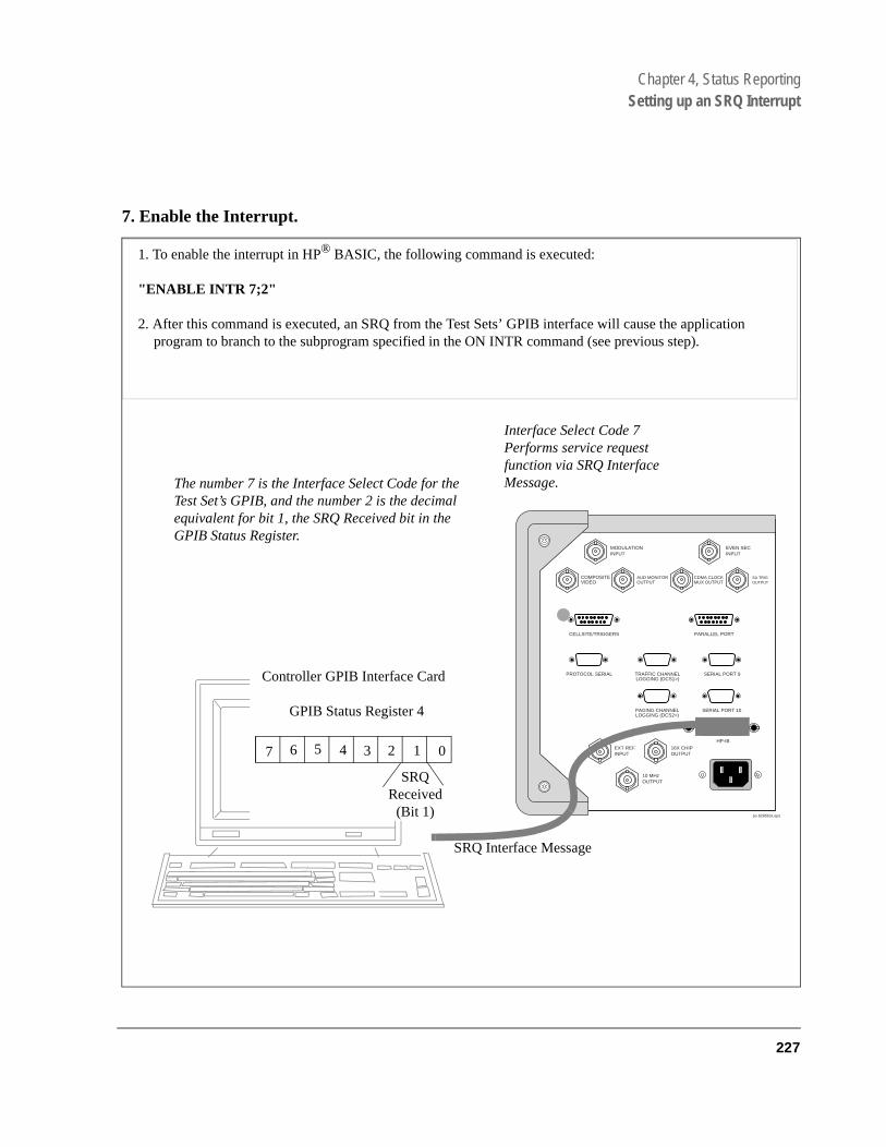
Chapter 4, Status ReportingSetting up an SRQ Interrupt
7. Enable the Interrupt.
MODULATIONINPUT
EXT REFINPUT
16X CHIPOUTPUT
10 MHzOUTPUT
COMPOSITEVIDEO
AUD MONITOROUTPUT
CDMA CLOCKMUX OUTPUT
SA TRIGOUTPUT
EVEN SECINPUT
CELLSITE/TRIGGERS PARALLEL PORT
PROTOCOL SERIAL TRAFFIC CHANNELLOGGING (DCS1>)
SERIAL PORT 9
PAGING CHANNELLOGGING (DCS2>)
SERIAL PORT 10
HP-IB
po 8285bck.eps
1. To enable the interrupt in HP® BASIC, the following command is executed:
"ENABLE INTR 7;2"
2. After this command is executed, an SRQ from the Test Sets’ GPIB interface will cause the application program to branch to the subprogram specified in the ON INTR command (see previous step).
Interface Select Code 7Performs service request function via SRQ Interface Message.
Controller GPIB Interface Card
GPIB Status Register 4
7 0123456
SRQ Received (Bit 1)
The number 7 is the Interface Select Code for the Test Set’s GPIB, and the number 2 is the decimal equivalent for bit 1, the SRQ Received bit in the GPIB Status Register.
SRQ Interface Message
227

Chapter 4, Status ReportingSetting up an SRQ Interrupt
ter
le, ,
8. Service the interrupt.
To re-enable the SRQ interrupt after branching to the line in your code that services the interrupt:
1. Clear the Status Byte Register. Example:
Status Byte = SPOLL (714).
NOTE: The SPOLL command queries the Status Byte Register. Bit 6 is the RQS bit, and should beset indicating that the Test Set requested service.
2. Query the Event Register. Example:
"STAT:CDMA:EVEN?"
Since our example set up an interrupt only on the CDMA Status Register Bit 3, Bit 3 should be true when you read the Event Register. This command also clears the con-tents of the CDMA Event Register.
3. Clear other Event Registers in the path to the Status Byte Register Group. Examples:
"STAT:OPER:EVEN?"
reads the Operation Status Register Group Event Register, clearing its contents so that another interrupt won’t be generated until the SMB from the CDMA Status RegisGroup is true.
"*CLS"
clears all the event register contents. (Using this command will work for this exampbut would not be a good choice if multiple events were generating SRQ interruptsbecause bits that flag other events would be cleared).
4. Re-enable the SRQ Interrupt.
"ENABLE INTR"
5. Branch to return line. Example:
GOTO XXX
228
S:\agilent\e8285\USRGUIDE\BOOK\CHAPTERS\hpibstat.fb

Chapter 4, Status ReportingSetting up an SRQ Interrupt
Example BASIC Program to Set Up and Service an SRQ Interrupt
The following HP® BASIC program was written for an HP® 9000 Series 300 Controller and an E8285A Test Set. The program assumes that the test set is the only instrument on the bus. The program sets up an interrupt from the Standard Event Status Register Group, the Calibration Status Register Group, and the Hardware Status Register #1 Group. For demonstration purposes the program is written to stay in a dummy loop waiting for an interrupt from the Test Set.
229

Chapter 4, Status ReportingSetting up an SRQ Interrupt
10 OPTION BASE 120 COM/Io_names/INTEGER Inst_address,Std_event_reg,Calibration_reg30 COM /Io_names/ INTEGER Hardware1_reg,Srq_enab_reg,Status_byte,Event_reg40 !50 ! Define E8285A instrument address60 Inst_address=71470 !80 PRINTER IS CRT90 CLEAR SCREEN100 !110 ! Reset the E8285A to bring it to a known state120 OUTPUT Inst_address;"*RST"130 !140 ! Clear the E8285A status reporting system150 OUTPUT Inst_address;"*CLS"160 !170 ! Set up the desired interrupt conditions in the E8285A:180 !190 ! 1) Standard Event Status Register Group200 ! Event register conditions which will set the Summary Message210 ! TRUE if they occur:220 ! Bit 5: Command Error decimal value = 2^5 = 32230 ! Bit 4: Execution Error decimal value = 2^4 = 16240 ! Bit 3: Device Dependent Error decimal value = 2^3 = 8250 ! Bit 2: Query Error decimal value = 2^2 = 4260 !270 Std_event_reg=32+16+8+4280 !290 ! Set up the Standard Event Status Enable Register to generate the300 ! Summary Message310 !320 OUTPUT Inst_address;"*ESE";Std_event_reg330 !340 ! 2) Calibration Status Register Group350 ! Condition register conditions which will set the Summary Message360 ! TRUE if they occur:370 ! Bit 4: TX Auto-zero failed decimal value = 2^4 = 16380 ! Bit 3: Voltmeter Self-cal failed decimal value = 2^3 = 8390 ! Bit 2: Counter Self-cal failed decimal value = 2^2 = 4400 ! Bit 1: Sampler Self_cal failed decimal value = 2^1 = 2410 ! Bit 0: Spec Anal Self-cal failed decimal value = 2^0 = 1420 !430 Calibration_reg=16+8+4+2+1440 !450 ! Set the Transition Filters to allow only positive transitions in460 ! the assigned condition(s) to pass to the Event Register470 !480 OUTPUT Inst_address;"STAT:CAL:PTR";Calibration_reg490 OUTPUT Inst_address;"STAT:CAL:NTR 0"500!
510 ! Set up the Calibration Status Register Group Enable Register to520 ! generate the Summary Message.530 !540 OUTPUT Inst_address;"STAT:CAL:ENAB";Calibration_reg550 !560 ! The Calibration Status Register Group Summary Message is passed to570 ! the Status Byte Register through Bit 8 in the Questionable580 ! Data/Signal Register Group Condition Register. The Questionable590 ! Data/Signal Register Group must be configured to set its Summary600 ! Message TRUE if the Summary Message from the Calibration Status610 ! Register Group is TRUE. Therefore Bit 8 (2^8=256) in the Questionable
230
S:\agilent\e8285\USRGUIDE\BOOK\CHAPTERS\hpibstat.fb

Chapter 4, Status ReportingSetting up an SRQ Interrupt
620 ! Data/Signal Register Group Enable Register must be set HIGH.630 !640 OUTPUT Inst_address;"STAT:QUES:ENAB 256"650 !660 ! 3) Hardware Status Register #1 Group670 ! Condition register conditions which will set the Summary Message680 ! TRUE if they occur:690 ! Bit 5: Measurement limits exceeded decimal value = 2^5 = 32700 ! Bit 4: Power-up Self-test failed decimal value = 2^4 = 16710 ! Bit 3: Overpower protection tripped decimal value = 2^3 = 8720 !730 Hardware1_reg=32+16+8740 !750 ! Set the Transition Filters to allow only positive transitions in760 ! the assigned condition(s) to pass to the Event Register770 !780 OUTPUT Inst_address;"STAT:HARD1:PTR";Hardware1_reg790 OUTPUT Inst_address;"STAT:HARD1:NTR 0"800 !810 ! Set up the Hardware Status Register #1 Group Enable Register to820 ! generate the Summary Message.830 !840 OUTPUT Inst_address;"STAT:HARD1:ENAB";Hardware1_reg850 !860 ! 4) Set the correct Summary Message bit(s) in the Service Request870 ! Enable Register to generate a Service Request (SRQ) if the880 ! Summary Message(s) become TRUE.890 ! Bit 5 = Standard Event Status Register Summary Message900 ! decimal value = 2^5 = 32910 ! Bit 3 = Questionable Data/Signal Register Group Summary Message920 ! decimal value = 2^3 = 8930 ! Bit 0 = Hardware Status Register #1 Group Summary Message940 ! decimal value = 2^0 = 1950 !960 Srq_enab_reg=32+8+1970 OUTPUT Inst_address;"*SRE";Srq_enab_reg980 !990 ! 5) Set up the Active Controller to respond to an SRQ interrupt:1000 ! Call subprogram Check_interrupt if an SRQ condition exists on select1010 ! code 7. The interrupt priority level is set to 15 (highest level).1020 !1030 ON INTR 7,15 CALL Srvice_interupt1040 !1050 ! 6) Enable interrupts on select code 7:1060 ! The interface mask is set to a value of 2 which enables interrupts on1070 ! the GPIB bus when the SRQ line is asserted.1080 !1090 ENABLE INTR 7;21100 !1110 ! Start of the dummy loop:1120 !1130 LOOP1140 DISP "I am sitting in a dummy loop."1150 END LOOP1160 !1170 END1180 !1190 Srvice_interupt:SUB Srvice_interupt1200 !1210 OPTION BASE 11220 COM /Io_names/ INTEGER Inst_address,Std_event_reg,Calibration_reg
231

Chapter 4, Status ReportingSetting up an SRQ Interrupt
1230 COM /Io_names/ INTEGER Hardware1_reg,Srq_enab_reg,Status_byte,Event_reg1240 !1250 !Turn off interrupts while processing the current interrupt.1260 OFF INTR 71270 !1280 !Conduct a SERIAL POLL to read the Status Byte and clear the SRQ:1290 !1300 Status_byte=SPOLL(Inst_address)1310 !1320 ! Determine which Register Group(s) caused the interrupt. Since three1330 ! were enabled, all three must be checked:1340 !1350 IF BIT(Status_byte,5) THEN GOSUB Srvice_std_evnt1360 IF BIT(Status_byte,3) THEN GOSUB Srvice_calib1370 IF BIT(Status_byte,0) THEN GOSUB Srvice_hard11380 !1390 ! Re-enable the interrupt before leaving the service routine1400 !1410 ENABLE INTR 7;21420 SUBEXIT1430 !1440 Srvice_std_evnt:!1450 ! This routine would determine which bit(s) in the Standard Event1460 ! Status Register are TRUE, logic 1, and take appropriate action.1470 ! NOTE: Read the Event Register to clear it. If the Event Register is1480 ! not cleared it will NOT latch another event, thereby preventing1490 ! the E8285A from generating another SRQ.1500 !1510 OUTPUT Inst_address;"*ESR?"1520 ENTER Inst_address;Event_reg1530 RETURN1540 !1550 Srvice_calib:!1560 ! This routine would determine which bit(s) in the Calibration Status1570 ! Register Group Event Register are TRUE, logic 1, and take1580 ! appropriate action.1590 ! NOTE: Read the Event Register to clear it. If the Event Register is1600 ! not cleared it will NOT latch another event from the Condition1610 ! Register, thereby preventing the E8285A from generating another SRQ.1620 !1630 OUTPUT Inst_address;"STAT:CAL:EVEN?"1640 ENTER Inst_address;Event_reg1650 RETURN1660 !
1670 Srvice_hard1:!1680 ! This routine would determine which bit(s) in the Hardware Status1690 ! Register #1 Group Event Register are TRUE, logic 1, and take1700 ! appropriate action.1710 ! NOTE: Read the Event Register to clear it. If the Event Register is1720 ! not cleared it will NOT latch another event from the Condition1730 ! Register, thereby preventing the E8285A from generating another SRQ.1740 !1750 OUTPUT Inst_address;"STAT:HARD1:EVEN?"1760 ENTER Inst_address;Event_reg1770 RETURN1780 !
1790 SUBEND
232
S:\agilent\e8285\USRGUIDE\BOOK\CHAPTERS\hpibstat.fb

5
Memory Cards/Mass Storage
233

Chapter 5, Memory Cards/Mass Storage
"Default File System" on page 235"Mass Storage Device Overview" on page 237"Default Mass Storage Locations" on page 244"Mass Storage Access" on page 246"DOS and LIF File System Considerations" on page 247"Using the ROM Disk" on page 253"Using Memory Cards" on page 254"Backing Up Procedure and Library Files" on page 260"Copying Files Using IBASIC Commands" on page 261"Using RAM Disk" on page 263"Using External Disk Drives" on page 265
234
S:\agilent\e8285\USRGUIDE\BOOK\CHAPTERS\memcard.fb
Chapter 5, Memory Cards/Mass StorageDefault File System
DOS
he
or
n on upon
Default File System
The Test Set’s default file system is the Microsoft®1 Disk Operating System (MS-DOS®). The DOS file system is used on IBM-compatible personal computers. (See "DOS File Naming Conventions" on page 248 for further information on the DOS file system.) This implies that the Test Set expects a formatted media for operations as shown in table 25 on page 236. If a LIF (Hewlett-Packard®’s Logical Interchange Format) formatted media is used for tactivities outlined in table 25 (with the exception of IBASIC mass storage operations), erroneous operation will result.
The IBASIC file system supports both LIF and DOS. The media format (DOSLIF) is determined automatically by the IBASIC file system when the mass storage device is first accessed, and the appropriate format is used from thefor IBASIC mass storage operations. File system operation defaults to DOS exiting from IBASIC.
NOTE: The IBASIC INITIALIZE command defaults to LIF format. Any media (RAM Disk,SRAM Cards, External Hard Disk Drive, or 3.5-inch floppy) formatted using the defaultconditions of the INITIALIZE command will be the LIF format and will be unusable exceptfor IBASIC mass storage operations. Refer to "Initializing Media for DOS or LIF FileSystem" on page 251 for information on formatting media for the DOS file system.
The IBASIC WILDCARDS command defaults to WILDCARDS OFF. To useDOS wildcards while in IBASIC execute the WILDCARDS DOS commandupon entering the IBASIC environment.
1. Microsoft® and MS-DOS ® are U.S. registered trademarks of Microsoft Corp.
235

Chapter 5, Memory Cards/Mass StorageDefault File System
Table 25 Test Set Default File System
Activity Default File
System
Manual front-panel operations
a. SAVE/RECALL register access b. TESTS Subsystem file access c. Signaling Decoder NMT file access
DOS
IBASIC mass storage operations LIF is default, DOS is also supported LIF
GPIB commands for
a. SAVE/RECALL register access b. TESTS Subsystem file accessc. Signaling Decoder NMT file access
DOS
TESTS Subsystem
a. Procedure files b. Library filesc. Code files
DOS
236
S:\agilent\e8285\USRGUIDE\BOOK\CHAPTERS\memcard.fb

Chapter 5, Memory Cards/Mass StorageMass Storage Device Overview
rnal
Test
t Set.ROM)inserted
Mass Storage Device Overview
As shown in figure 34 on page 238, the Test Set has both internal and external mass storage devices. There are five types of mass storage devices in the Test Set:
• On-board random-access memory disk (RAM disk) located on the Test Set’s intememory board
• On-board read-only memory disk (ROM disk) located on the Test Set’s internal memory board
• External disk drives connected to the Test Set’s external GPIB
• Internal static random access memory (SRAM) cards which are inserted into the Set’s front-panel Memory Card slot
NOTE: The hardware for reading-from and writing-to memory cards is located internal to the TesTherefore, the static random access memory (SRAM) cards and the read only memory (cards are considered internal to the Test Set even thought the physical media must be into the Test Set’s front-panel Memory Card slot.
Programs and data can be retrieved from any of these mass storage devices. Programs and data can only be stored to RAM disk, external disk, or SRAM card mass storage devices. The IBASIC file system supports both the LIF file system and the MS-DOS file system.
237

Chapter 5, Memory Cards/Mass StorageMass Storage Device Overview
Figure 34 Internal and External Mass Storage Devices
Microprocessor
On Board RAM
RAM Diskmemory, 0, nn= 0, 1, 2, 3
External Disk Drive
GPIB I/O:,7XX,n
XX= 0 to 30n= 0,1
GPIB Rear Panel
GPIB LIF CS803 1/2” Drive9122, 9133/4,9153, 9154
On Board ROM
ROM Disk:Memory, 0, 4
Inte
rnal
Dat
a B
us
Front Panel Memory Card
Slot
:INTERNAL, 4ROM or SRAM
Card
238
S:\agilent\e8285\USRGUIDE\BOOK\CHAPTERS\memcard.fb

Chapter 5, Memory Cards/Mass StorageMass Storage Device Overview
Mass Storage Device Types
The following paragraphs provide an overview of the five types of mass storage devices.
Typical Uses
• Temporary program and data storage • Temporary Save/Recall register storage
Comments
• Easily overwritten or erased
• Not recommended for permanent program or data storage
• Unit 0 can be overwritten by the RAM_MANAGER utility program (ROM Disk)
• Unit 1 can be overwritten by the COPY_PL utility program (ROM Disk)
• Units 2 and 3 are not overwritten by any ROM Disk utility program
Table 26 RAM Disk Mass Storage Overview
Mass Storage Name
Mass Storage Type
Physical Location Mass Storage Volume
Specifier Media Type
Supported File
System(s)
RAM Disk Non-volatilerandom accessmemory
Test Set’s internalmemory board
":MEMORY,0,unit number"unit number = 0, 1, 2, or 3 default = 0
N/A LIF, DOS
239
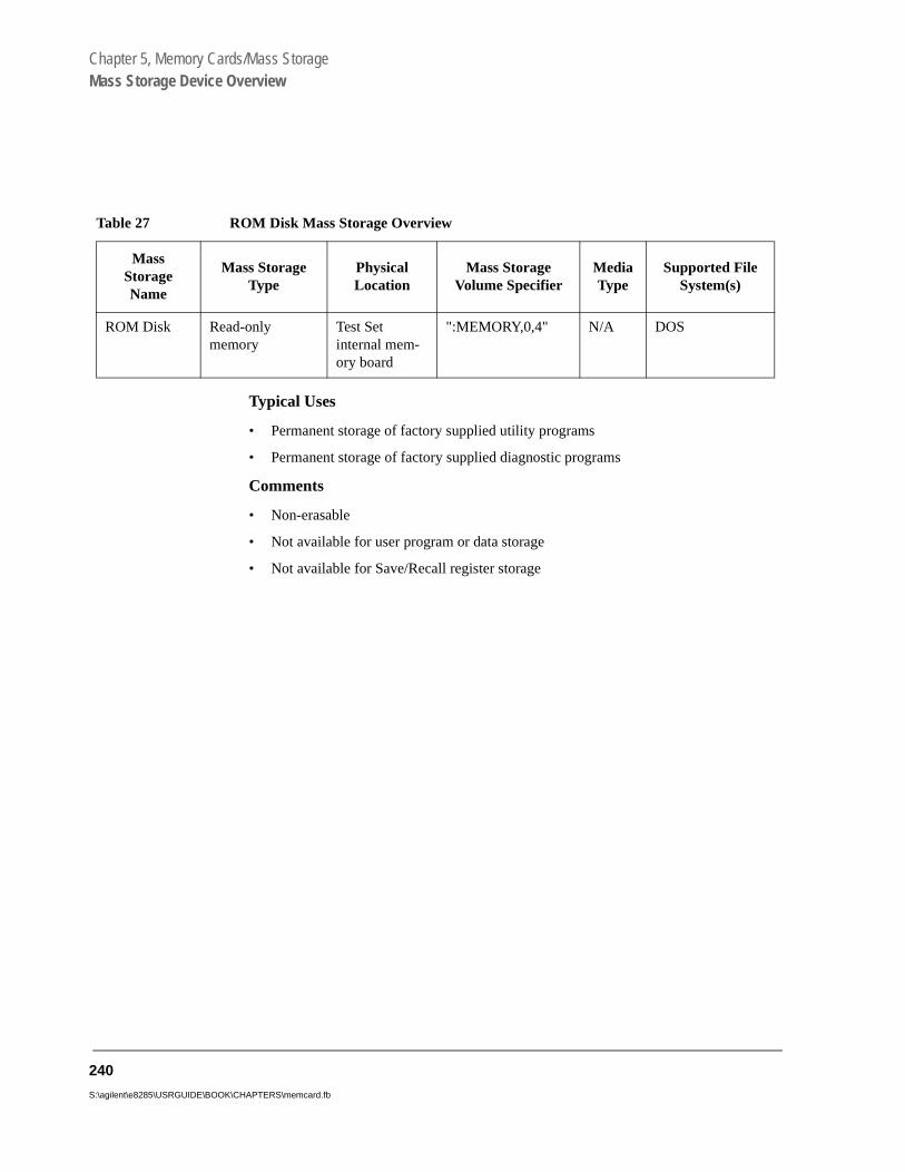
Chapter 5, Memory Cards/Mass StorageMass Storage Device Overview
Typical Uses
• Permanent storage of factory supplied utility programs
• Permanent storage of factory supplied diagnostic programs
Comments
• Non-erasable
• Not available for user program or data storage
• Not available for Save/Recall register storage
Table 27 ROM Disk Mass Storage Overview
MassStorageName
Mass StorageType
PhysicalLocation
Mass StorageVolume Specifier
MediaType
Supported FileSystem(s)
ROM Disk Read-onlymemory
Test Setinternal mem-ory board
":MEMORY,0,4" N/A DOS
240
S:\agilent\e8285\USRGUIDE\BOOK\CHAPTERS\memcard.fb

Chapter 5, Memory Cards/Mass StorageMass Storage Device Overview
Typical Uses
• Permanent program and data storage
• Permanent Save/Recall register storage
Comments
• High capacity (device dependent)
• Slowest access time of Test Set’s mass storage devices
Table 28 External Disk Mass Storage Overview
MassStorageName
MassStorage
Type
PhysicalLocation
Mass Storage VolumeSpecifier
Media TypeSupported
FileSystem(s)
External Disk
GPIB Harddisk driveGPIB Floppy disk drive
Connected toTest Set’sexternal GPIB
":,7xx,n"xx = device address (0-30)n = unit number (range device dependent)
Hard disk = NA Floppy disk 3.5-in DS Disk
LIF, DOS
241

Chapter 5, Memory Cards/Mass StorageMass Storage Device Overview
slot
Typical Uses
• Semi-permanent program and data storage
• Semi-permanent Save/Recall register storage
Comments
• Low capacity
• Contents retained by on-card lithium battery
• Contents lost if on-card battery removed while card not in Test Set Memory Card
• Recommended as primary mass storage device for program and data storage
Table 29 SRAM Card Mass Storage Overview
MassStorageName
Mass Storage Type PhysicalLocation
Mass StorageVolume
Specifier Media Type
SupportedFile
System(s)
SRAMMemoryCard
Static Random-AccessMemory Card
Plugs intoMemoryCard slot onfront panelof Test Set
":INTER-NAL,4"
PCMCIA Type 1 or Type 2 SRAM Memory Card
LIF, DOS
242
S:\agilent\e8285\USRGUIDE\BOOK\CHAPTERS\memcard.fb

Chapter 5, Memory Cards/Mass StorageMass Storage Device Overview
Typical Uses
• Permanent storage of factory supplied application programs
• Permanent storage of factory supplied utility programs
• Permanent storage of factory supplied diagnostic programs
Comments
• Non-erasable
• Not available for user program or data storage
• Not available for Save/Recall register storage
Table 30 ROM Card Mass Storage Overview
MassStorageName
MassStorage
Type
PhysicalLocation
Mass StorageVolume
Specifier Media Type
SupportedFile
System(s)
ROM orOTPMemory Card
Read-onlyMemoryCard
Plugs into Memory Card slot on front panel of Test Set
":INTERNAL,4" PCMCIA Type 1orType 2 EPROMMemory Card
DOS
243
Chapter 5, Memory Cards/Mass StorageDefault Mass Storage Locations
et’s
cated
Default Mass Storage Locations
Built-in IBASIC Controller
The default mass storage location for the built-in IBASIC Controller is the front- panel memory card slot (mass storage volume specifier ":INTERNAL,4") after any of the following conditions:
• power-up
• initializing RAM with the SERVICE screen’s RAM Initialize function
The mass storage location for the built-in IBASIC Controller can be changed using the MASS STORAGE IS command. Refer to the HP® Instrument BASIC Users Handbook for further information on the MASS STORAGE IS command.
Save/Recall Registers
The default mass storage location for the Save/Recall registers is the Test Sinternal RAM (no mass storage volume specifier) after any of the following conditions:
• Power-up
• Initializing RAM with the SERVICE screen’s RAM Initialize function
• Resetting the Test Set using the front-panel Preset key
• Resetting the Test Set using the *RST GPIB Common Command
The mass storage location for Save/Recall registers can be changed using the Save/Recall field in the I/O CONFIGURE screen. The default mass storage volume specifiers for the Save/Recall register mass storage locations are as follows:
• Internal selection - (no mass storage volume specifier, registers are saved to alloRAM space)
• Card selection (not changeable) - ":INTERNAL,4"
• RAM selection (not changeable) - ":MEMORY,0,0"
• Disk selection - the External Disk Specification field in the TESTS (External Devices) screen.
244
S:\agilent\e8285\USRGUIDE\BOOK\CHAPTERS\memcard.fb

Chapter 5, Memory Cards/Mass StorageDefault Mass Storage Locations
External Disk Drive
The default mass storage volume specifier for the external disk drive is set using the External Disk Specification field in the TESTS (External Devices) screen.
TESTS Subsystem
The default mass storage location for the TESTS Subsystem is set using the Select Procedure Location: field on the TESTS (Main Menu) screen. The default mass storage volume specifiers for the TESTS Subsystem mass storage locations are as follows:
• Card selection (not changeable) - ":INTERNAL,4"
• ROM selection (not changeable) - “:MEMORY,0,4”
• RAM selection (not changeable) - ":MEMORY,0,0"
• Disk selection - the External Disk Specification field in the TESTS (External Devices) screen.
Selecting the Mass Storage Location
The IBASIC mass storage location is selected using the IBASIC Mass Storage Is command. The mass storage volume specifier for the desired mass storage location is appended to the Mass Storage Is command. Refer to the HP® Instrument BASIC User’s Handbook for further information regarding the Mass Storage Is command.
For example, to change the default mass storage location to RAM Disk unit 2, execute the following command:
Mass Storage Is ":MEMORY,0,2"
The Mass Storage Is command is keyboard and program executable; however, any changes made are lost when the Test Set is turned off or when the SERVICE screen’s RAM Initialize function is executed.
245
Chapter 5, Memory Cards/Mass StorageMass Storage Access
ns can
ram
re b-are pre-
es are
st be
tions,
Mass Storage Access
Program and data files stored on the Test Set’s various mass storage locatiobe selectively accessed from the following screens:
• The TESTS (IBASIC Controller) screen.
Any type of file can be accessed from this screen, either through an IBASIC progor the IBASIC command line.
• The TESTS (Main Menu) screen using the Select Procedure Location: and Select Procedure Filename: fields.
Only procedure files shipped with Agilent Technologies 83217 software or procedufiles created using the TESTS (Save/Delete Procedure) screen of the TESTS Susystem can be accessed using these fields. When created, procedure file names fixed with a lower case .PRC file extension (FM_TEST.PRC).
A corresponding code file - prefixed with .PGM (FM_TEST.PGM must reside on the same media for the procedure to work. Refer to the TESTS Screen chapter in the Agilent Technologies E8285A Reference Guide for further information.
• The TESTS (Save/Delete Procedure) screen using the Select Procedure Location: and Enter Procedure Filename: fields.
This screen is used to create “procedure” files. When created, procedure file namprefixed with a .PRC file extension (FM_TEST.PRC).
• The Signaling Decoder screen in NMT mode.
Only user-written NMT tests can be accessed from this screen. NMT test files musaved with a .NMT file extension (NMT_1.NMT).
Save/Recall register files, stored on the Test Set’s various mass storage locacan be accessed using the front-panel Save and Recall keys.
246
S:\agilent\e8285\USRGUIDE\BOOK\CHAPTERS\memcard.fb

Chapter 5, Memory Cards/Mass StorageDOS and LIF File System Considerations
DOS and LIF File System Considerations
Program and data files can be stored and retrieved from IBASIC using either the DOS or LIF file system. The media format (DOS or LIF) is determined automatically by the IBASIC file system when the mass storage device is first accessed, and the appropriate format is used from then on. DOS and LIF use different file naming conventions. In addition, the Test Set uses certain file naming conventions which are unique to the Test Set. Unexpected file operation can occur if proper consideration is not given to the file naming conventions.
247

Chapter 5, Memory Cards/Mass StorageDOS and LIF File System Considerations
HP
File Naming Conventions
LIF File Naming Conventions
The LIF file system is used by Hewlett-Packard® BASIC on the HP® 9000 Series 200/300 Workstations. It is a flat file system, which means that it has no subdirectories. The LIF file system allows up to 10-character file names which are case sensitive. The LIF file system preserves the use of uppercase and lowercase characters for file storage and retrieval. For example, the file names File1, FILE1, file1 and FiLe1 could represent different files. LIF files cannot start with a space, and any file name longer than 10 characters is considered an error.
NOTE: The Test Set’s file system does not support the HFS (hierarchical file system) used with®
BASIC. Therefore, no directory path information can be used during mass storage operationswith LIF files.
DOS File Naming Conventions
The DOS file system is used on IBM compatible personal computers. The DOS file system is hierarchical, which means it supports subdirectories. The DOS file system allows up to 8-character file names with an optional extension of up to 3 characters. The file name is separated from the extension (if it exists) with a period (.). DOS file names are case independent. The characters are stored as upper case ASCII in the DOS directory but the files may be referenced without regard to case. The DOS file system always converts any lowercase characters to uppercase when files are stored. For example, the file names File1, FILE 1 , file1 and FiLe1 all represent the single DOS file FILE1 .
The period (.) may appear in the name but only to separate the file name from the extension. The period is not considered part of the file name itself. If the name portion of a DOS file name is longer than 8 characters, it is truncated to 8 characters and no error is generated. Similarly, if the extension is longer than 3 characters, it is truncated to 3 characters and no error is given.
248
S:\agilent\e8285\USRGUIDE\BOOK\CHAPTERS\memcard.fb

Chapter 5, Memory Cards/Mass StorageDOS and LIF File System Considerations
onto tem.
file
ame
nded
file
Test Set File Naming Conventions
The TESTS Subsystem uses the following file naming conventions:
• The .PGM extension is used to indicate a code file and is automatically appended the file name when the program code file is stored for use by the TESTS Subsys
• The .PRC extension is used to indicate a procedure file and is appended onto thename when the file is stored by the TESTS Subsystem
• The .LIB extension is used to indicate a library file and is appended onto the file nwhen the file is created for use with the TESTS Subsystem
The Save/Recall register subsystem uses the following file naming convention:
• The .SAV extension is used to indicate a stored Save/Recall register file and is appeonto the file name when the file is created
The Signaling Decoder in NMT mode uses the following file naming convention:
• The .NMT extension is used to indicate a stored NMT file and is appended onto thename when the file is created
Test Set File Entry Field Width
The TESTS Subsystem and the Save/Recall register subsystem have fields into which the operator enters a file name. These fields are used by the operator to enter the name of a file to be stored or loaded. The width of these fields is 8 characters and was chosen to support the DOS file naming convention of 8 characters. Consequently these fields will not hold a 10-character file name which is allowed in the LIF file system.
249

Chapter 5, Memory Cards/Mass StorageDOS and LIF File System Considerations
not a
ch is
not
trun-ult in
trun-ult in
Potential File Name Conflicts
Unexpected file operation can occur if proper consideration is not given to the different file system naming conventions and the file entry field width.
• A full DOS file name is 12 characters (8-character file name + . + 3 character extension). A full DOS file name will not fit in the Test Set’s file entry field.
• On a DOS formatted disk, any file with the .PGM extension is considered a TESTS Subsystem code file. If the TESTS Subsystem attempts to retrieve a file which is code file, the following error will be generated: Error reading code file. Check file and media.
• On a DOS formatted disk, any file with the .PRC extension is considered a TESTS Subsystem procedure file. If the TESTS Subsystem attempts to retrieve a file whinot a procedure file, the following error will be generated: Error reading procedure file. Check file and media.
• On a DOS formatted disk, any file with the .LIB extension is considered a TESTS Subsystem library file. If the TESTS Subsystem attempts to retrieve a file which isa library file, the following error will be generated: Error reading library file. Check file and media.
• When copying LIF named files to a DOS formatted media, the file name is silently cated to 8 characters since DOS only allows 8-character file names. This could resERROR 54 Duplicate File Name.
• When storing or deleting files to a DOS formatted media, the file name is silently cated to 8 characters since DOS only allows 8-character file names. This could resERROR 54 Duplicate File Name.
File Naming Recommendations
If switching between media types (DOS and LIF) or operating exclusively in DOS the following naming conventions are recommended.
• Ensure that only TESTS Subsystem procedure files use the .PRC file extension.
• Ensure that only TESTS Subsystem library files use the .LIB file extension.
• Ensure that only TESTS Subsystem code files use the .PGM file extension.
• Ensure that only user-written NMT test files use the .NMT file extension.
• Ensure that only Save/Recall register files use the .SAV file extension.
250
S:\agilent\e8285\USRGUIDE\BOOK\CHAPTERS\memcard.fb

Chapter 5, Memory Cards/Mass StorageDOS and LIF File System Considerations
card
m
the
Initializing Media for DOS or LIF File System
The PCMCIA field, found on the I/O CONFIGURE screen, provides a convenient way to format PCMCIA cards up to 1 MByte. This field activates the same function that occurs when an unformatted card is inserted into the Test Set’s slot and the user responds with Yes to the message prompt.
The INITIALIZE command is used to initialize a media (external hard disk, external 3.5-inch floppy disk, Epson SRAM Card, PCMCIA SRAM Card and RAM Disk) for use with the DOS or LIF file system. The DOS or LIF file systeis specified with the parameter. LIF is the default.
For example, to initialize a PCMCIA SRAM card for the DOS file system, perform the following steps:
1. Put the PCMCIA SRAM card into the Test Set’s front-panel Memory Card slot.
2. Display the TESTS (IBASIC Controller) screen.
3. Using the rotary knob or an external terminal, execute the following command fromIBASIC Controller command line:
INITIALIZE "DOS:INTERNAL,4"
Refer to the HP® Instrument BASIC User’s Handbook for further information regarding the INITIALIZE command.
Test Set File Types
The Test Set file system supports the following file types:
• ASCII - files containing ASCII characters
• BDAT - files containing binary data
• DIR - DOS subdirectory
• DOS - SAVEd code file
• IBPRG - STOREd code file
251

Chapter 5, Memory Cards/Mass StorageDOS and LIF File System Considerations
tem being
ed”
g the
sing
Storing Code Files
Two IBASIC commands are available for storing program code to a mass storage location: SAVE and STORE. The type of file created by the Test Set’s file syswhen the program code is stored, is dependent upon the format of the mediaused. The type of file created verses the media format is outlined in table 31. The IBASIC 2.0 file system can distinguish between DOS files that have been “savand those that were “stored.”
Files that have been stored using the SAVE command must be retrieved usinGET command:
SAVE "FM_TEST:,704,1"GET "FM_TEST:,704,1"
Files that have been stored using the STORE command must be retrieved uthe LOAD command:
STORE "FM_TEST:,704,1"LOAD "FM_TESTS:,704,1"
Table 31 Sorted Program Code File Types
DOSFormatted
Media
LIFFormatted
Media
SAVE DOS ASCII
STORE IBPRG IBPRG
252
S:\agilent\e8285\USRGUIDE\BOOK\CHAPTERS\memcard.fb

Chapter 5, Memory Cards/Mass StorageUsing the ROM Disk
Using the ROM Disk
The Test Set comes with several Test Procedures stored on the internal ROM disk. These Test procedures provide instrument diagnostic utilities, periodic calibration utilities, memory management utilities, a variety of general purpose utilities, and several IBASIC demonstration programs.
To see a brief description of what each procedure does perform the following steps:
1. Display the TESTS (Main Menu) screen by selecting the front-panel Tests key.
2. Using the rotary knob, select the Select Procedure Location: field and choose ROM from the choices.
3. Using the rotary knob, select the Select Procedure Filename field. A list of Test Procedures stored on the ROM disk is displayed in the Choices: field. Using the rotary knob, select the Test Procedure of interest.
4. A brief description of the Test Procedure will be displayed in the Description field.
ROM DISK cannot be written to for user storage.
The ROM Disk’s mass storage volume specifier is ":MEMORY,0,4"
For example, to catalogue the contents of the ROM Disk from the TESTS (IBASIC Controller) screen enter:
CAT ":MEMORY,0,4"
253

Chapter 5, Memory Cards/Mass StorageUsing Memory Cards
Using Memory Cards
OTP (One Time Programmable) cards provide removable read-only storage. File editing and erasure are not possible. These cards cannot be programmed by the Test Set; they require a special memory card programmer to save files.
SRAM cards provide removable read/write memory for your files, similar to a flexible disk. Data can be stored, re-stored, read, or erased as needed.
SRAM memory cards require a battery to maintain stored information.
254
S:\agilent\e8285\USRGUIDE\BOOK\CHAPTERS\memcard.fb
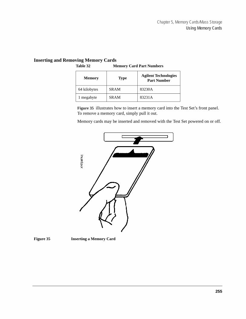
Chapter 5, Memory Cards/Mass StorageUsing Memory Cards
el.
r off.
Inserting and Removing Memory Cards
Figure 35 illustrates how to insert a memory card into the Test Set’s front panTo remove a memory card, simply pull it out.
Memory cards may be inserted and removed with the Test Set powered on o
Figure 35 Inserting a Memory Card
Table 32 Memory Card Part Numbers
Memory Type Agilent Technologies
Part Number
64 kilobytes SRAM 83230A
1 megabyte SRAM 83231A
255

Chapter 5, Memory Cards/Mass StorageUsing Memory Cards
your
otectat thery.
ttery tery
telycked
The Memory Card Battery
SRAM memory cards use a lithium battery to power the card. SRAM cards typically retain data for over 1 year at 25° C. To retain data, the battery should be replaced annually. The part number for the SRAM Card Battery is CR2025 or Agilent Technologies part number 1420-0509.
Replacing the Battery
1. Turn the Test Set on and insert the memory card. An inserted memory card takes power from the Test Set, preventing the card’s contents from being lost.
2. Hold the memory card in the slot with one hand and pull the battery holder out with other hand. (See figure 36 .)
NOTE: The HP SRAM cards have a Battery Holder Lock switch immediately above the Write-Prswitch. If the switch is in the locked position the battery cannot be removed. Ensure thBattery Holder Lock switch is in the unlocked position before trying to remove the batte
3. Install the battery with the side marked “+” on the same side marked “+” on the baholder. Avoid touching the flat sides of the battery, finger oils may contaminate batcontacts in the memory-card.
4. Re-insert the battery holder into the memory card.
NOTE: The Agilent Technologies SRAM cards have a Battery Holder Lock switch immediaabove the Write-Protect switch. Ensure that the Battery Holder Lock switch is in the loposition after installing the new battery.
5. Remove the memory card from the Test Set.
256
S:\agilent\e8285\USRGUIDE\BOOK\CHAPTERS\memcard.fb

Chapter 5, Memory Cards/Mass StorageUsing Memory Cards
e
Figure 36 Replacing the Memory Card’s Battery
WARNING: Do not mutilate, puncture, or dispose of batteries in fire. The batteries can burst orexplode, releasing hazardous chemicals. Discard unused batteries according to thmanufacturer’s instructions.
NL Batterij nietweggooien, maarinleveren als KCA.
257
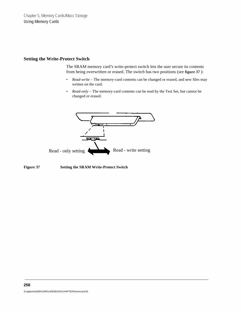
Chapter 5, Memory Cards/Mass StorageUsing Memory Cards
ts
may
e
Setting the Write-Protect Switch
The SRAM memory card’s write-protect switch lets the user secure its contenfrom being overwritten or erased. The switch has two positions (see figure 37 ):
• Read-write – The memory-card contents can be changed or erased, and new fileswritten on the card.
• Read-only – The memory-card contents can be read by the Test Set, but cannot bchanged or erased.
Figure 37 Setting the SRAM Write-Protect Switch
Read - only setting Read - write setting
258
S:\agilent\e8285\USRGUIDE\BOOK\CHAPTERS\memcard.fb

Chapter 5, Memory Cards/Mass StorageUsing Memory Cards
IC
torage o e with .
be
has
to
Memory Card Mass Storage Volume Specifier
The front-panel memory card slot’s mass storage volume specifier is ":INTERNAL,4" and is the default mass storage device for the Test Set. For example, to catalogue the contents of a memory card from the TESTS (IBASController) screen, execute the following IBASIC command:
CAT ":INTERNAL,4"
or, if the mass storage location has not been changed,
CAT
If the MSI (Mass Storage Is) command has been used to change the mass slocation to a different device, the ":INTERNAL,4" designation must be used taccess the memory card slot. Any changes to the mass storage location madthe MSI (Mass Storage Is) command are lost when the Test Set is turned off
Memory Card Initialization
All new SRAM cards must be initialized before they can be used to store information. The RAM_MNG procedure stored on the internal ROM Disk canused to quickly initialize any SRAM memory card.
SRAM Memory Cards can also be initialized from the TESTS (IBASIC Controller) screen by inserting the memory card into the front-panel slot and executing the following IBASIC command:
INITIALIZE "<volume type>:INTERNAL,4"
where the <volume type> can be LIF or DOS. To verify that the memory cardbeen properly initialized, execute the IBASIC command:
CAT ":INTERNAL,4"
If the error message ERROR 85 Medium uninitialized appears on the screenthe memory card has not been properly initialized. Check the SRAM battery ensure that it’s charged and inserted correctly in the battery holder.
259

Chapter 5, Memory Cards/Mass StorageBacking Up Procedure and Library Files
ry m type
7
Backing Up Procedure and Library Files
Making a backup copy of procedure and library files helps guard against file loss due to memory card (or battery) failure.
Using the COPY_PL ROM Program
The COPY_PL procedure on the internal ROM Disk will make backup copies of TESTS Subsystem’s Procedure and Library files onto a second SRAM memocard, and can also initialize an uninitialized SRAM memory card. This progradoes not make backup copies of TESTS Subsystem’s code files, or copy anyof file to OTP memory cards.
The COPY_PL procedure is designed for use with Agilent Technologies 8321software to make backup copies of Agilent Technologies supplied or user-generated Procedure and Library files.
To Run COPY_PL
1. Access the TESTS (Main Menu) screen.
2. Select the Select Procedure Location: field and choose ROM.
3. Select the Select Procedure Filename: field and select IB_UTIL.
4. Select the Run Test softkey to start the procedure.
5. Follow the displayed instructions.
260
S:\agilent\e8285\USRGUIDE\BOOK\CHAPTERS\memcard.fb
Chapter 5, Memory Cards/Mass StorageCopying Files Using IBASIC Commands
ory
Copying Files Using IBASIC Commands
Files can be copied from one mass storage device to another using the IBASIC COPY command. For example, to copy a file from a memory card to the left drive of an external dual-disk drive with a mass storage volume specifier of ":,702,0", execute the following IBASIC command from the TESTS (IBASIC Controller) command line:
COPY "FM_TEST:INTERNAL,4" TO "FM_TEST:,704,0"
“Stored” or “saved” files on one memory card can be copied to another memcard as follows:
• Insert the memory card containing the file to be copied.
• LOAD or GET1 the desired file from the memory card into the Test Set.
• Remove the original memory card.
• Insert the destination memory card in the Test Set.
• STORE or SAVE1 the file to the destination memory card.
1. See "Storing Code Files" on page 252 for information about the LOAD, GET, STORE, and SAVE commands.
261

Chapter 5, Memory Cards/Mass StorageCopying Files Using IBASIC Commands
Copying an Entire Volume
An entire volume can be copied from one mass storage device to the same type of mass storage device using the volume copy form of the COPY command. The destination volume must be as large as, or larger than, the source volume. The directory and any files on the destination volume are destroyed. The directory size on the destination volume becomes the same size as the source media. Disc-to-disc copy time is dependent on the mass storage device type. The volume copy form of the COPY command was designed to copy like-media to like-media and like-file-systems to like-file-systems. For example, to copy the entire contents of one internal RAM disk to another internal RAM disk, execute the following IBASIC command from the TESTS (IBASIC Controller) command line:
COPY ":MEMORY,0,0" TO ":MEMORY,0,1"
NOTE: Using the volume copy form of the COPY command can produce unexpected results. Forexample, using the volume copy form to copy the contents of a 64-KB SRAM card to an external GPIB 630-KB floppy disk will result in the external floppydisk having a capacity of only 64 KB when the volume copy is finished. Furthermore all fileson the floppy disk before the volume copy was executed will be lost and are not recoverable.Additionally, the file system type on the source media (LIF or DOS) is forced onto thedestination media. Caution should be exercised when using the volume copy form of theCOPY command.
The Test Set only supports the following types of volume copy using the volumecopy form of the COPY command:
1. Like- media to like-media (RAM disk to RAM disk, external floppy to external floppy, and so forth)
2. Like-file-system to like-file-system (DOS to DOS, LIF to LIF)
All other types of volume copy are unsupported and will produce unexpectedresults or system errors.
Using wildcards in the COPY command can eliminate the need to use the volume form of the COPY command. Refer to the HP® Instrument BASIC User’s Handbook for further information on wildcards and their use in the COPY command.
262
S:\agilent\e8285\USRGUIDE\BOOK\CHAPTERS\memcard.fb

Chapter 5, Memory Cards/Mass StorageUsing RAM Disk
set n rased,
as a ts.
1, 2,
en’son-
Using RAM Disk
RAM Disk is a section of the Test Set’s internal RAM memory that has been aside for use as a mass storage device. RAM Disk acts much the same as aexternal disk drive; that is, program and data files can be stored, re-stored, eand retrieved from the RAM Disk.
The RAM Disk is partitioned into four separate units: 0-3. Each unit is treatedseparate “disk.” The size of each disk can be specified in 256-byte incremen
The four RAM Disk units are designated ":MEMORY,0,0" to ":MEMORY,0,3".For example, to catalog the contents of RAM Disk unit “0” from the TESTS (IBASIC Controller) screen, execute the following command:
CAT ":MEMORY,0,0"
Volume 0’s contents can be viewed and loaded from the TESTS (IBASIC Controller) screen, the TESTS (Main Menu) screen, the TESTS (Save/DeleteProcedure) screen and the Signaling Decoder screen in NMT mode. Volumesand 3 can only be accessed from the TESTS (IBASIC Controller) screen.
NOTE: RAM Disk Erasure. The contents of RAM Disk are easily lost. Unit 0 can be overwritten bythe RAM_MNG utility program (ROM Disk). Unit 1 can be overwritten by the COPY_PLutility program (ROM Disk). The contents of all units are lost when the SERVICE screRAM Initialize function is executed. Therefore, RAM Disk should only be used for npermanent, short-term storage of program or data files.
263

Chapter 5, Memory Cards/Mass StorageUsing RAM Disk
Initializing RAM Disks
Each RAM Disk unit must be initialized before it can be used. Unit 0 can be initialized using the RAM_MNG procedure stored on internal ROM Disk. Volumes 1, 2, and 3 must be initialized from the TESTS (IBASIC Controller) screen.
The optional “unit size” parameter in the following procedure specifies the memory area, in 256 byte blocks, set aside for each disk unit.
Follow these steps to initialize volumes 1, 2, or 3:
1. Access the TESTS (IBASIC Controller) screen.
2. Using the rotary knob or an external terminal, enter and execute the IBASIC command:
INITIALIZE ":MEMORY,0,<unit number 1-3>",<unit size>
For example:
INITIALIZE ":MEMORY,0,1",50
NOTE: The IBASIC INITIALIZE command defaults to LIF format. Any media (RAM Disk, SRAMCards, External Hard Disk Drive, or 3.5-inch floppy) formatted using the default conditionsof the INITIALIZE command will be the LIF format and will be unusable in the Test Set,except for IBASIC mass storage operations. Refer to "Initializing Media for DOS or LIFFile System" on page 251 for information on formatting media for the DOS file system.
264
S:\agilent\e8285\USRGUIDE\BOOK\CHAPTERS\memcard.fb

Chapter 5, Memory Cards/Mass StorageUsing External Disk Drives
Using External Disk Drives
The Test Set supports only GPIB external disk drives. Certain configuration information is required by the Test Set to access external disk drives.
The I/O CONFIGURE screen’s GPIB Mode field must be set to Control any timean external disk drive is used by the Test Set.
To load files from the TESTS screens or NMT Signaling Decoder screen, thedisk’s mass storage volume specifier must be entered in the External Disk Specification field on the TESTS (External Devices) screen (for example,:,702,1).
265

Chapter 5, Memory Cards/Mass StorageUsing External Disk Drives
Initializing External Disks
All new external disk media must be initialized before it can be used to store information. External disk media can be initialized for either LIF (Logical Interchange Format) or DOS (Disk Operating System) format using the Test Set. (See "DOS and LIF File System Considerations" on page 247.)
External disk media can be initialized from the TESTS (IBASIC Controller) screen by inserting the new media into the external disk drive and executing the following IBASIC command:
INITIALIZE "<volume type>:<external disk mass storage volumespecifier>"
where the <volume type> can be LIF or DOS
For example:
INITIALIZE "DOS:,702,1").
To verify that disk media has been properly initialized, execute the IBASIC command:
CAT "<external disk mass storage volume specifier>"
For example:
CAT ":,702,1"
NOTE: The IBASIC INITIALIZE command defaults to LIF format. Any media (RAM Disk, SRAMCards, External Hard Disk Drive or 3.5-inch floppy) formatted using the default conditions ofthe INITIALIZE command will be the LIF format and will be unusable in the Test Set, exceptfor IBASIC mass storage operations. Refer to "Initializing Media for DOS or LIF FileSystem" on page 251 for information on formatting media for the DOS file system.
266
S:\agilent\e8285\USRGUIDE\BOOK\CHAPTERS\memcard.fb

6
IBASIC Controller
267

Chapter 6, IBASIC Controller
"Introduction" on page 269"The IBASIC Controller Screen" on page 270"Important Notes for Program Development" on page 272"Program Development" on page 273"Interfacing to the IBASIC Controller using Serial Ports" on page 275"Choosing Your Development Method" on page 287"Method #1. Program Development on an External BASIC Language Computer" on page 289"Method #2. Developing Programs on the Test Set Using the IBASIC EDIT Mode" on page 296"Method #3. Developing Programs Using Word Processor on a PC (Least Pre-ferred)" on page 302"Uploading Programs from the Test Set to a PC" on page 309"Serial I/O from IBASIC Programs" on page 310"PROGram Subsystem" on page 312"The TESTS Subsystem" on page 338
268
S:\agilent\e8285\USRGUIDE\BOOK\CHAPTERS\ibasic.fb

Chapter 6, IBASIC ControllerIntroduction
Set’s es, is ntly ted
ded o n
Introduction
The Test Set contains an instrument controller that can run programs to control the various instruments in the Test Set and instruments/devices connected to the Test Set’s external I/O ports (GPIB, serial and parallel).
The instrument controller runs a subset of the Hewlett-Packard® Rocky Mountain BASIC programming language called Instrument BASIC or IBASIC. Using this programming language it is possible to develop programs which use the Testinstruments to automatically test a variety of radios. Software, the 83217 seriavailable from Agilent Technologies for testing the major radio systems currein use today. Users can also develop their own IBASIC programs for automaradio testing.
This chapter is designed to provide the programmer with the information neeto develop IBASIC programs for use on the built-in IBASIC controller. Refer tthe individual Agilent Technologies 83217 software manuals for information ousing the IBASIC controller with Agilent Technologies supplied software.
269
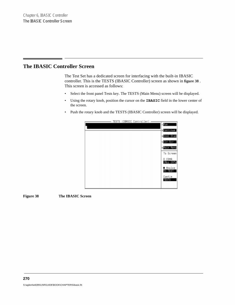
Chapter 6, IBASIC ControllerThe IBASIC Controller Screen
d.
d.
The IBASIC Controller Screen
The Test Set has a dedicated screen for interfacing with the built-in IBASIC controller. This is the TESTS (IBASIC Controller) screen as shown in figure 38 . This screen is accessed as follows:
• Select the front panel Tests key. The TESTS (Main Menu) screen will be displaye
• Using the rotary knob, position the cursor on the IBASIC field in the lower center of the screen.
• Push the rotary knob and the TESTS (IBASIC Controller) screen will be displaye
Figure 38 The IBASIC Screen
270
S:\agilent\e8285\USRGUIDE\BOOK\CHAPTERS\ibasic.fb

Chapter 6, IBASIC ControllerThe IBASIC Controller Screen
The TESTS (IBASIC Controller) screen can be accessed programmatically by sending the following command:
OUTPUT 714;"DISP TIBasic"
The TESTS (IBASIC Controller) screen is divided into several areas which are used by the IBASIC controller for different purposes.
The small horizontal rectangle at the top left is the IBASIC command line. As the name implies IBASIC commands can be executed from this line. Commands can be entered locally using the rotary knob or remotely using serial port 9. A maximum of 100 characters may be entered into the command line.
The vertical rectangle at the top right side is the softkey label area. The five highlighted areas within the softkey label area correspond to the five special function keys on the front panel of the Test Set. IBASIC programs can assign tables to these keys and control program execution by using ON KEY interrupts.
The vertical rectangle at the bottom right side is the To Screen area and is the same as the To Screen area displayed on any other Test Set screen. The user may switch to some other Test Set screen by using the rotary knob to position the cursor onto the desired screen and then pushing the knob.
The large rectangle in the center of the screen is the CRT (display screen) for the IBASIC controller. The IBASIC controller uses this area for, displaying alpha, numeric, and graphic information, program editing, program listing and so forth. This area operates as would the CRT on an external Hewlett-Packard® 9000 Series 200/300 Workstation.
271

Chapter 6, IBASIC ControllerImportant Notes for Program Development
licate
ke a IBA-
panel R).
STSortinge. The
Important Notes for Program Development
The Test Set is designed to operate the same way under automatic control as it does under manual control. This has several implications when designing and writing programs for the Test Set:
• To automate a particular task, determine how to do the task manually and then dupthe steps in the program.
• In Manual Control mode, a Test Set function must be displayed and “active” to mameasurement or receive DUT data. Therefore, to make a measurement using anSIC program, follow these basic steps:
1. Use the DISPlay command to select the screen for the instrument whose front contains the desired measurement result or data field (such as AF ANALYZE
2. Set the measurement field (such as SINAD) to the ON state.
3. Trigger a reading.
4. Read the result.
NOTE: The following sections discuss developing IBASIC programs which do not use the TESubsystem. Programs written for the TESTS Subsystem require the creation of suppLibrary, Procedure, and Code files, and must be written using a specific program structurAgilent Technologies 83217A Software packages are examples of this type of program.
272
S:\agilent\e8285\USRGUIDE\BOOK\CHAPTERS\ibasic.fb
Chapter 6, IBASIC ControllerProgram Development
Program Development
There are three recommended approaches for developing IBASIC programs. They are outlined in figure 39 and discussed in more detail later in this chapter. Since the Test Set only has the rotary knob and numeric keypad for data/character entry, developing programs on the Test Set alone is not recommended. All three development methods employ an external computer or terminal. The choice of development method will typically be driven by available equipment and extent of development task. If the development task is large, it is strongly recommended that a BASIC language computer be used as outlined in development Method #1.
Method #2 is recommended for large program modification or smaller program development. Method #2 uses an external PC or terminal as the CRT and keyboard for the built-in IBASIC controller.
Method #3 is least preferred for program development or modification because no syntax checking occurs until the program is first run making it difficult to debug long programs. Details of each development method are given later in this chapter.
273

Chapter 6, IBASIC ControllerProgram Development
Figure 39 Program Development Methods
Develop on Test Setusing screen"EDIT" mode
Run program inIBASIC environment
Develop in Word Processor on PC
Download into Test Set over RS-232 using terminal emulator program
Develop on BASIC Language Computer external to Test Set
Connect HP-IB cable to Test Set and run program from external computer
Debug Run Program
Debug
Debug
Save program in mass storage
Method 1 Method 2 Method 3(Not Recommended)
Change Address in program anddownload into Test Set
Verify program operation in IBASIC environment
Save program in mass storage
Save program in mass storage
ch6drw2.drw
274
S:\agilent\e8285\USRGUIDE\BOOK\CHAPTERS\ibasic.fb

Chapter 6, IBASIC ControllerInterfacing to the IBASIC Controller using Serial Ports
#2 serial
Interfacing to the IBASIC Controller using Serial Ports
This section describes how to interconnect the Test Set to an external PC or terminal using the Test Set’s serial I/O ports. Program development methodsand #3 use PC’s or terminals connected to the Test Set through the Test Set’sI/O ports. To determine which programming environment best fits your application, refer to "Choosing Your Development Method" on page 287.
Test Set Serial Port Configuration
To prepare for IBASIC program development, the Test Set must first be configured to operate with a PC or terminal.
This includes,
• Hardware
• Cables
• Screens - I/O CONFIGURE and TESTS (IBASIC Controller)
There are two independently controllable serial interfaces in the Test Set, Serial Port 9 and Serial Port 10. The IBASIC Controller can send and receive data from either port by using its assigned select code.
275
Chapter 6, IBASIC ControllerInterfacing to the IBASIC Controller using Serial Ports
Serial Port Information
Serial Port 9. Serial Port 9 is used for developing and editing IBASIC programs since it can be connected directly to the IBASIC Command Line field. It can also be used for data I/O from an IBASIC program. Settings can be changed from the I/O CONFIGURE screen, using IBASIC commands executed from the IBASIC Command Line field, or using IBASIC commands executed from an IBASIC program.
Serial Port 10. Serial Port 10 is primarily used for data I/O from an IBASIC program to a device-under-test- (DUT). Settings can be changed using IBASIC commands executed from the IBASIC Command Line field, or using IBASIC commands executed from an IBASIC program but not from the I/O CONFIGURE screen.
Reason for Two Serial Ports
A typical application uses serial port 10 to send and receive data to and from a DUT and uses serial port 9 to print or log test results to a serial printer or PC.
In the program development environment, serial port 9 can be used to communicate with the external PC or terminal, and serial port 10 can be connected to a serial printer for generating program listings or as the destination printer for the program itself. If simultaneous multiple serial I/O is not a requirement then only use serial port 9 as it can directly access the IBASIC Command Line field.
276
S:\agilent\e8285\USRGUIDE\BOOK\CHAPTERS\ibasic.fb

Chapter 6, IBASIC ControllerInterfacing to the IBASIC Controller using Serial Ports
Code R IS nged
e f the e dis-r the
Serial Port 9 Configuration
Table 33 on page 278 and the following paragraphs describe how to configure Serial Port 9 for communications with an external PC or terminal. Implications of the various choices are discussed.
1. Under the To Screen menu, select More, then select IO CONFIG.
2. The I/O CONFIGURE screen will be displayed.
3. Set the Serial Baud, Parity, Data Length, Stop Length, and Flow Cntl fields to match your PC or terminal settings. The recommended settings are shown in table 33 on page 278. These settings will be retained by the Test Set. They will not change if the Preset key is pressed, if the Test Set receives a *RST Common Command, or the power is turned on and off.
4. Set the Serial_9 field to Inst. This routes Serial Port 9 to the IBASIC Command Line field. Characters typed on the external PC or terminal will now appear in the IBASIC Command Line.
5. Set the IBASIC Echo field to ON. This will cause IBASIC character output from commands (such as LIST, PRINT or DISPLAY) or error messages to echo characters to Serial Port 9 (the characters will in turn show up on the external PC or terminal screen). This will allow program listings and syntax error messages to be seen on the external PC or terminal.
6. Another method which can be used to output characters to the external PC or terminal is to execute the IBASIC command, PRINTER IS 9. This causes IBASIC to direct all print output to Select Code 9. Select Code 9 is the Test Set’s Serial Port 9. Select1 is the Test Set’s CRT. Select Code 1 is also the default address for the PRINTEcommand, so all program printer output defaults to the Test Set’s CRT (unless chawith the PRINTER IS command).
7. Set the Inst Echo field to ON. This will cause characters to be echoed back to thexternal PC or terminal as they are received at Serial Port 9. If the echo feature oexternal PC or terminal is also enabled all the characters sent to the Test Set will bplayed twice on the external PC or terminal. Enable echo on only one device, eitheTest Set or the external PC or terminal.
277

Chapter 6, IBASIC ControllerInterfacing to the IBASIC Controller using Serial Ports
re,
t y.
size of
Receive and Transmit Pacing
When receiving characters into the IBASIC Command Line field, the Test Set’s microprocessor responds to each entry and no buffering is required. Therefowhen using your PC or terminal to send characters to the IBASIC Command Line field, it is permissible to set Flow Cntl to None.
When sending data through the Test Set’s Serial Port to external devices likeprinters which may have small input buffers, it is important to set RFlow Cntl to Xon/Xoff. This allows the printer to stop data transmission from the Test Sewhen the printer’s buffer is full and then start it again when the printer is read
The Test Set has a Serial Port input buffer length of 2000 characters. Buffer becomes important when IBASIC programs expect to receive large amountsdata through the Serial Port with a single ENTER statement.
Table 33 Test Set Serial Port 9 Configuration
Field Available Settings Recommended Setting
Serial In Inst/IBASIC Inst
IBASIC Echo On/Off On
Inst Echo On/Off On
Serial Baud Rate 150, 300, 600, 1200, 2400, 4800, 9600, 19200
9,600
Parity None, Odd, Even, Always 1, Always 0
None
Data Length 7 bits, 8 bits 8 bits
Stop Length 1 bit, 2 bits 1 bit
Flow Cntl None, Xon/Xoff, Hardware Xon/Xoff
278
S:\agilent\e8285\USRGUIDE\BOOK\CHAPTERS\ibasic.fb

Chapter 6, IBASIC ControllerInterfacing to the IBASIC Controller using Serial Ports
C.
ng s
. It the
uter
ed
PC Configuration
To prepare for IBASIC program development, the external PC or terminal must be configured to operate with the Test Set. This configuration includes
• hardware • terminal Emulator Software
PC Serial Port Configuration
Connect the Test Set’s Serial Port 9 to a serial I/O (input/output) port on the POn many PCs, a serial port is available as either a 25-pin DB-25 (female) connector or a 9-pin DB-9 (male) connector. This port can be configured as COM1, COM2, COM3, or COM4 (communications port 1, 2, 3, or 4) dependion the installed PC hardware and user-defined setup. Refer to the instructionshipped with the PC for hardware and software configuration information.
Terminal Emulator Configuration Information
A “terminal emulator” is an application program running on the PC that communicates with one of the serial communication ports installed in the PCprovides a bi-directional means of sending and receiving ASCII characters toTest Set’s serial port.
In general, a “terminal emulator” enables the PC to act like a dedicated compterminal. This type of terminal was used before PCs to allow remote users tocommunicate through RS232 with central mainframe computers. An ANSI-compatible terminal like the Digital Equipment Corporation VT-100 can be usto directly communicate with the Test Set. PC terminal emulation applicationprograms have been designed to have setup fields much like these older technology terminals.
279

Chapter 6, IBASIC ControllerInterfacing to the IBASIC Controller using Serial Ports
Setting Up Microsoft Windows Terminal on your PC (Windows Version 3.1)
1. From the Program Manager, select the Accessories Group.
2. Select the Terminal icon.
3. From the Settings menu, make the following choices:
a. Select Terminal Emulator.
1. DEC VT-100 (ANSI).
b. Select Terminal Preferences.
1. Terminal Modes
Line Wrap: Off Local Echo: Off Sound: Off
2. Columns: 132
3. CR->CR/LF
Inbound: Off Outbound: Off
4. Cursor
Block Blink: On
5. Terminal Font: Fixedsys
6. Translations: None
7. Show Scroll Bars: On
8. Buffer Lines: 100
9. Use Function, Arrow, and Ctrl Keys for Windows: OFF
c. Select Test Transfer.
1. Flow Control: Standard Flow Control
2. Word wrap Outgoing Text at Column: Off
280
S:\agilent\e8285\USRGUIDE\BOOK\CHAPTERS\ibasic.fb

Chapter 6, IBASIC ControllerInterfacing to the IBASIC Controller using Serial Ports
d. Select Communications (the first five of the following Communications choices for your PC Serial Port should match your Test Set settings).
1. Baud Rate: 9600
2. Data Bits: 8
3. Stop Bits: 1
4. Parity: None
5. Flow Control: Xon/Xoff
6. Connector: COM1, COM2, COM3, or COM4 depending on your PC setup
7. Parity Check: Off
8. Carrier Detect: Off
281
Chapter 6, IBASIC ControllerInterfacing to the IBASIC Controller using Serial Ports
’s n a
Setting Up ProComm Revision 2.4.3 on your PC
ProComm is a general purpose telecommunications software package for PCwith MS-DOS. One of its functions is to provide an RS-232 terminal function otypical PC.
Running ProComm in MSDOS (You can use ProComm’s built-in help function tolearn more about setting it up).
1. To access the help and command functions, press the Alt and F10 keys simultaneously (abbreviated as Alt+F10).
2. Press the space bar to move among the choices for a particular field.
3. Press ENTER to accept the displayed choice.
Setting up the ProComm Software
1. Press Alt+ P to access the LINE SETTINGS window.
2. Enter the number 11. This will automatically set the following:
Baud rate: 9600 Parity: None Data Bits: 8 Stop Bits: 1 Selected communications port: COM1 (This may be different on your PC)
3. To select a different communications port, enter the following numbers:
20: COM1 21: COM2 22: COM3 23: COM4
4. Enter the number 24 to save changes, to make the new configuration your default, and to exit LINE SETTINGS.
5. Press Alt+S for the SETUP MENU.
6. Enter the number 1 for MODEM SETUP .
7. Enter the number 1 for the Modem init string .
8. Press Enter to set a null string.
9. Press Esc to exit MODEM SETUP back to the SETUP MENU.
10. Enter the number 2 for TERMINAL SETUP.
282
S:\agilent\e8285\USRGUIDE\BOOK\CHAPTERS\ibasic.fb

Chapter 6, IBASIC ControllerInterfacing to the IBASIC Controller using Serial Ports
11. Terminal emulation: VT-100
Duplex: FULL Flow Control: XON/XOFF CR translation (in): CR CR translation (out): CR BS translation: NON-DEST BS key definition: BS Line wrap: ON Scroll: ON Break length (ms): 350 Enquiry (CNTL-E): OFF
12. Press Esc to exit Terminal Setup back to the Setup Menu.
13. Enter the number 4 for General Setup.
Translate Table: OFF Alarm sound: OFF Alarm time (secs): 1 Aborted downloads: KEEP
14. Press Esc to exit General Setup back to the Setup Menu.
15. On the Setup Menu, press S to save your entries.
16. Press Esc to exit the Setup Menu.
17. Press Alt+X to exit ProComm back to MS-DOS.
Setting Up Agilent Technologies AdvanceLink ( 68333F Version B.02.00) on your PC
Agilent Technologies AdvanceLink is a software program which allows PCs to be used as an alphanumeric or graphics terminal. It can also automate terminal and file-transfer functions. The version described will work with PCs with the MS-DOS or PC-DOS operating systems. (AdvanceLink for Windows is also available, and configuration is very similar).
Running AdvanceLink in MSDOS
1. Press the Tab key to move from one field to the next, which also accepts the displayed choice.
2. Press the NEXT CHOICE and PREVIOUS CHOICE keys to move among the choices for a particular field.
Setting up the AdvanceLink Software
1. Press the TERMINAL function key.
2. Press Config KEYS.
283

Chapter 6, IBASIC ControllerInterfacing to the IBASIC Controller using Serial Ports
3. Press GLOBAL CONFIG.
Keyboard: USASCII Personality: ANSI Language: ENGLISH Terminal Mode: Alphanumeric Remote To: enter your PC’s selected serial port number, often, Serial 1 Printer I/F: None Memory Size: 32K Plotter I/F: None Video Type: select your display type Forms Path: no entry Screen Size: select your size — 23 or 24
4. Press DONE to return to the Config screen.
5. Press REMOTE CONFIG (to set up the Serial port you selected above in Remote To).
Baud Rate: 9600 Parity/DataBits: None/8 Enq Ack: NO Asterisk: OFF Chk Parity: NO SR(CH): LO Recv Pace: Xon/Xoff CS(CB)Xmit: NO XmitPace: Xon/Xoff
284
S:\agilent\e8285\USRGUIDE\BOOK\CHAPTERS\ibasic.fb

Chapter 6, IBASIC ControllerInterfacing to the IBASIC Controller using Serial Ports
6. Press DONE to return to the Config screen.
7. Press TERMINAL CONFIG.
Terminal Id: 2392A LocalEcho: OFF CapsLock: OFF Start Col: 01 Bell: ON XmitFnctn(A): NO SPOW(B): NO InhEolWrp(C): NO Line/Page(D): LINE InhHndShk(G): NO Inh DC2(H): NO Esc Xfer(N): YES ASCII 8 Bits: YES Fld Separator: down arrow or US BlkTerminator: up arrow or RS ReturnDef: musical note or CR Copy: Fields Type Ahead: NO Row Size: 160 Host Prompt Character: left arrow or D1 Horiz. Scrolling Increment: 08
8. Press DONE to return to the Config screen.
9. Press DONE to return to the Terminal screen.
10. Press MAIN to return to the Main screen.
11. Press EXIT ADVLINK to exit.
285

Chapter 6, IBASIC ControllerInterfacing to the IBASIC Controller using Serial Ports
s on
Terminal Configuration
Terminals typically have a DB-25 (male) connector. Set the terminal for DEC VT-100 ANSI emulation. Many ASCII terminals will also function properly.
To set up the terminal, use the field settings found in the Agilent Technologies AdvanceLink terminal emulator section found earlier in this chapter. As a minimum, make sure the terminal’s basic setup information matches the fieldthe Test Set’s I/O CONFIGURE screen (refer to table 33 on page 278 for recommended settings).
286
S:\agilent\e8285\USRGUIDE\BOOK\CHAPTERS\ibasic.fb

Chapter 6, IBASIC ControllerChoosing Your Development Method
Choosing Your Development Method
There are three fundamental methods for developing IBASIC programs for the Test Set. See figure 40 below.
Figure 40 Three Possible Development Methods
Develop on Test Setusing screen"EDIT" mode
Run program inIBASIC environment
Develop in Word Processor on PC
Download into Test Set over RS-232 using terminal emulator program
Develop on BASIC Language Computer external to Test Set
Connect HP-IB cable to Test Set and run program from external computer
Debug Run Program
Debug
Debug
Save program in mass storage
Method 1 Method 2 Method 3(Not Recommended)
Change Address in program anddownload into Test Set
Verify program operation in IBASIC environment
Save program in mass storage
Save program in mass storage
ch6drw2.drw
287

Chapter 6, IBASIC ControllerChoosing Your Development Method
asily
to the ays n
ger
with is
he t and ing
after l
ger
Method 1
Using a BASIC language computer (either an HP® technical computer or a PC running BASIC with GPIB) is the best method for developing any size program. This is because the program can be debugged directly on the external computer before downloading the program into the Test Set. Using this approach the programmer can observe the Test Set’s display to see changes in state and everify the correct measurements.
Method 2
If a BASIC language computer is not available, program development can bedone directly on the Test Set using the IBASIC EDIT mode. A PC connectedthe Test Set through RS-232, as described earlier in this chapter, is used as CRT and keyboard for the internal controller. In this method, the program alwresides in the Test Set and can be run at any time. Mass storage is usually aSRAM card. When running IBASIC programs on the Test Set’s internal controller, the Test Set displays only the IBASIC screen, not the individual instrument screens as the program executes. This makes troubleshooting larprograms more difficult.
Method 3
The third method of program development is to use a word processor on a PCRS-232, and then download the program into the Test Set for execution. Thisthe least favorable choice for development because downloading code into tTest Set over RS-232 requires a loader utility program running in the Test Sea RAM memory card present as an intermediate storage location before runnthe program. (For shorter programs, the intermediate storage location is not necessary.) No IBASIC command syntax is checked until the program is run downloading. Also, when running IBASIC programs on the Test Set’s internacontroller, the Test Set displays only the IBASIC screen, not the individual instrument screens as the program executes. This makes troubleshooting larprograms more difficult.
288
S:\agilent\e8285\USRGUIDE\BOOK\CHAPTERS\ibasic.fb

Chapter 6, IBASIC ControllerMethod #1. Program Development on an External BASIC Language Computer
Method #1. Program Development on an External BASIC Language Computer
Figure 41 Connecting IBASIC Language Computers to the Test Set
289
Chapter 6, IBASIC ControllerMethod #1. Program Development on an External BASIC Language Computer
l”
Configuring the Test Set’s GPIB Interface
To use GPIB (the IEEE 488 interface bus) as a means of communicating with the Test Set, connect a standard GPIB cable (such as the Agilent Technologies 10833B) between the Test Set’s rear-panel GPIB connector and the GPIB connector on the external BASIC language computer.
On the Test Set 1. Select the I/O CONFIGURE screen.
2. Set the Mode field to Talk&Lstn.
NOTE: If the Mode field is set to Control, there could possibly be a System Controller conflictbetween the external BASIC language computer and the Test Set, resulting in either anInterface Status Error or “lock up” of the GPIB. Refer to “Passing Instrument Contro inthe Operating Overview chapter of the Agilent Technologies E8285A User’s Guide.
3. Set the GPIB Adrs field to the desired address for the Test Set. The default value is 14.
Compatible BASIC Language Computers
As shown in figure 41 on page 289, there are two types of computers that can be used in this development method. The preferred computer is an HP® 9000 Series 200/300 Workstation running HP® Rocky Mountain BASIC 6.2 or later. IBASIC is a subset of HP® Rocky Mountain BASIC (RMB). All IBASIC commands are compatible with RMB and thus will execute from a HP® 9000 Series 200/300 Workstation.
If this is not available, a PC running a BASIC language environment, such as TransEra HT BASIC 4.0 and an GPIB card can be used. If this approach is used ensure that no BASIC language commands are used in the program which are not compatible with IBASIC.
290
S:\agilent\e8285\USRGUIDE\BOOK\CHAPTERS\ibasic.fb
Chapter 6, IBASIC ControllerMethod #1. Program Development on an External BASIC Language Computer
the
ge
Set to Set’s uage rnal or is he f PIB
Program Development Procedure
The Test Set has two GPIB buses, an internal GPIB at select code 8 and an external GPIB at select code 7. The Test Set’s built-in IBASIC controller usesinternal GPIB to communicate with the Test Set’s various instruments and devices. The process of developing a program on an external BASIC languacomputer utilizes this hardware feature to an advantage. First, develop the program directly on the external BASIC language computer treating the Testas a device on the external BASIC language computer’s GPIB. For example,setup the Test Set’s RF Generator use the OUTPUT command with the TestGPIB address. If the select code of the GPIB card in the external BASIC langcomputer is 7 and the address of the Test Set is 14 the address following theOUTPUT command would be 714. When the command executes on the exteBASIC language computer the information on how the Test Set’s RF Generatto be configured is sent to the Test Set through its external GPIB bus. After tprogram is fully developed, making it run on the Test Set is simply a matter ochanging the address of all the GPIB commands to 8XX (Test Set internal Gbus) and downloading the program into the Test Set’s IBASIC controller and executing it.
291

Chapter 6, IBASIC ControllerMethod #1. Program Development on an External BASIC Language Computer
There are two ways of allowing easy conversion of all GPIB commands to a different address. The first way is to establish a variable to which the 3-digit address number is assigned.
For example
10 Addr = 714 ! Sets the value of variable Addr to be 714.20 OUTPUT Addr;"*RST" ! Commands the Test Set to reset at address 714.
To change the address, simply change the value of variable Addr to 814.
For example
10 Addr = 814 ! Sets the value of variable Addr to be 814.20 OUTPUT Addr;"*RST" ! Commands the Test Set to reset at address 814.
A second method is to assign an I/O path to the desired I/O port.
For example
To control device #14 on the port with select code 7.
10 ASSIGN @Device TO 714! Establishes I/O path to select code 7 address 14.20 OUTPUT @Device;"*RST"! Commands Test Set to reset at address 714.
To change the address, simply change line 10 to
10 ASSIGN @Device TO 800.
NOTE: The dedicated GPIB interface at select code 8 conforms to the IEEE 488.2 Standard in allrespects but one. The difference being that each instrument on the bus does not have aunique address. The Instrument Control Hardware determines which instrument is beingaddressed with the command syntax. As such an explicit device address does not have tobe specified. The address 800 and 814 are equally correct.
292
S:\agilent\e8285\USRGUIDE\BOOK\CHAPTERS\ibasic.fb

Chapter 6, IBASIC ControllerMethod #1. Program Development on an External BASIC Language Computer
t an be r. to
Downloading Programs to the Test Set through GPIB
An IBASIC PROGram subsystem has been developed to allow the external BASIC language controller to download programs to the Test Set through GPIB (refer to the "PROGram Subsystem Commands" on page 315 for more information on the PROGram Subsystem). Four commands from the external BASIC language controller to the Test Set are necessary to transfer the program. The commands are executed serially allowing enough time for each command to finish executing. (The Test Set’s GPIB Mode field must be set to Talk&Lstn, and the TESTS (IBASIC CONTROLLER) screen must be displayed).
1. OUTPUT 714;"PROG:DEL:ALL"
Deletes any programs that reside in Test Set RAM.
2. OUTPUT 714;"PROG:DEF #0"
Defines the address in Test Set RAM where the downloaded program will be stored.
3. LIST #714
Causes all program lines to transfer over GPIB to the Test Set which is at address 714.
4. OUTPUT 714;" "END
Defines end of download process by generating an EOI command.
After the above commands complete the program code will be in the Test Seready to run. If any bugs are detected when the program is run, the program cuploaded back into the external BASIC language controller to correct the erroAlternately the full screen IBASIC EDIT function through RS-232 can be usedcorrect the error (refer to "Method #2. Developing Programs on the Test Set Using the IBASIC EDIT Mode" on page 296 for details).
After the program is working properly in the Test Set IBASIC environment, it should be stored for backup purposes.
293

Chapter 6, IBASIC ControllerMethod #1. Program Development on an External BASIC Language Computer
Uploading Programs from the Test Set to an External BASIC Controller through GPIB
To upload a program from the Test Set to an external BASIC language controller through GPIB the following program, which uses a command from the PROGram subsystem to initiate the upload, must be running on the external BASIC language controller. The uploaded program is stored to a file specified by the user.
In the following program the external BASIC language controller is a PC running TransEra HT BASIC. The file is stored to the C:\HTB386 directory. If the external BASIC language controller is an HP® 9000 Series 200/300 Workstation, modify the mass storage volume specifier appropriately. After running the program, the uploaded program code will be in the designated file. Use the GET command to retrieve the file for editing.
294
S:\agilent\e8285\USRGUIDE\BOOK\CHAPTERS\ibasic.fb

Chapter 6, IBASIC ControllerMethod #1. Program Development on an External BASIC Language Computer
10 ! PROGRAM TO UPLOAD IBASIC CODE FROM TEST SET TO BASIC CONTROLLER THROUGH GPIB.20 !######################################################################30 !40 ! The file for uploaded code will be "C:\htb386\code".50 ! If you want to use a different file or directory, modify the two lines60 ! with the labels "File_name_1" and "File_name_2".70 !80 !####################################################################90 Addr=714 !Test Set GPIB address100 ALLOCATE Line$[200]110 PRINTER IS 1120 CLEAR SCREEN130 DISP "It may be several minutes before code begins transferring if the program is long"140 OUTPUT Addr;"*RST" !Reset the Test Set150 OUTPUT Addr;"DISP TIB" !Displays the IBASIC screen160 OUTPUT Addr;"PROG:EXEC ’CLS’" !Clears the Test Set display170 OUTPUT 714;"PROG:DEF?" !Initiates the upload of whole program180 ENTER Addr USING "X,D,#";Count_len !Number of lines in program190 ENTER Addr USING VAL$(Count_len)&"D,#";Char_count !Number of characters200 !210 File_name_1: CREATE ASCII "C:\htb386\code",(1.05*Char_count/256)+5220 ! Number of records reserved for upload.230 File_name_2: ASSIGN @File TO "C:\htb386\code"240 !250 DISP "Transferring code from Test Set"260 LOOP !Program transfer loop.270 ENTER Addr;Line$ !CR/LF terminates each line.280 PRINT Line$ !Displays new lines on Test Set display.290 OUTPUT @File;Line$ !Transfer new line to file.300 Char_count=Char_count-LEN(Line$)-2 !Reduces Char_count by the number of310 ! characters in current line.320 EXIT IF Char_count<=0330 END LOOP340 !350 ASSIGN @File TO * !Cleans out file buffer.360 ENTER Addr;Line$ !Close off reading370 CLEAR SCREEN380 DISP "Transfer complete."390 LOCAL Addr400 END
295

Chapter 6, IBASIC ControllerMethod #2. Developing Programs on the Test Set Using the IBASIC EDIT Mode
es
al al or r de
Method #2. Developing Programs on the Test Set Using the IBASIC EDIT Mode
If a BASIC language computer is not available, program development can be done directly on the Test Set using the IBASIC EDIT mode. A terminal or PC connected to the Test Set through RS-232 is used as the CRT and keyboard for the Test Set’s built-in IBASIC controller. In this method, the program always residin the Test Set and can be run at any time. Mass storage is usually an SRAMmemory card. When running IBASIC programs on the Test Set’s internal controller, the Test Set displays only the IBASIC screen.
The Test Set’s IBASIC controller has an editor that is interactive with a terminor PC over the RS-232 serial port. (The editor does not work unless a terminPC with terminal emulator is connected to Serial Port 9.) The editor, hereaftereferred to as the “IBASIC EDIT Mode”, allows the programmer to develop codirectly in the Test Set with no uploading or downloading. The IBASIC EDIT Mode can be used to develop programs from scratch or to modify existing programs. Refer to "Interfacing to the IBASIC Controller using Serial Ports" on page 275 for information on connecting a terminal or PC to the Test Set.
296
S:\agilent\e8285\USRGUIDE\BOOK\CHAPTERS\ibasic.fb

Chapter 6, IBASIC ControllerMethod #2. Developing Programs on the Test Set Using the IBASIC EDIT Mode
Selecting the IBASIC Command Line Field
To use the IBASIC EDIT Mode for program development, the IBASIC Command Line field must be displayed on the Test Set and Serial Port 9 must be connected to the IBASIC Command Line field. An IBASIC command, sent as a series of ASCII characters through Serial Port 9, will appear on the IBASIC Command Line field. When a carriage return/line feed is encountered, the Test Set will attempt to execute the command. To display the IBASIC Command Line field on the Test Set execute the following steps:
1. Press the Tests key.
2. The TESTS (Main Menu) screen will be displayed.
3. Using the rotary knob, position the cursor on the IBASIC Cntrl field and select it.
4. The TESTS (IBASIC CONTROLLER) screen will be displayed.
5. The small horizontal rectangle at the top-left is the IBASIC Command Line
297

Chapter 6, IBASIC ControllerMethod #2. Developing Programs on the Test Set Using the IBASIC EDIT Mode
t
To Access the IBASIC Command Line Field
1. Position the cursor on the screen’s upper left. This is the IBASIC Command Line field.
2. The IBASIC Command Line field does not have a title like other fields in the TesSet; it is the highlighted, horizontal 2-line “bar” just below the screen title, TESTS(IBASIC Controller).
To Use the IBASIC Command Line Field with the Test Set’s Rotary Knob
1. Position the cursor at the IBASIC Command Line field and push the knob.
2. A Choices: field will be displayed in the lower, right corner of the display.
3. By rotating the knob, a list of ASCII characters and cursor positioning commands can be displayed on the right side of the screen.
4. When the cursor is next to the desired character or command, push the knob to select that character.
5. No external hardware is required for this entry method, but it is tedious and is recom-mended only for short commands. Use this method when doing simple tasks such as initializing memory cards or CATaloging a memory card.
6. Program development using the rotary knob alone is not recommended.
298
S:\agilent\e8285\USRGUIDE\BOOK\CHAPTERS\ibasic.fb

Chapter 6, IBASIC ControllerMethod #2. Developing Programs on the Test Set Using the IBASIC EDIT Mode
n
IC
or
se rminals n Test tly. In DIT
here e pace
Entering and Exiting the IBASIC EDIT Mode
To enter the IBASIC EDIT Mode first position the cursor on the IBASIC Command Line field, type the word EDIT on the terminal or PC connected to the Test Set and then press the Enter key on the terminal or PC. At this point the Test Set will fill the PC screen with 22 lines of IBASIC code from the program currently in the Test Set’s RAM memory. No program lines will be displayed othe Test Set screen. If no program is currently in the Test Set’s memory, the number 10 will be displayed on the terminal or PC screen. This represents program line number 10 and is displayed to allow you to begin writing an IBASprogram beginning at line number 10. The “*” annunciator will be displayed inthe upper, right corner of the Test Set indicating that the IBASIC controller is running to support the full screen edit mode.
After editing is complete, exit the IBASIC EDIT Mode by pressing the terminalPC’s ESCAPE key twice or pressing the Shift Cancel keys on the Test Set.
A variety of editing commands are supported by the IBASIC EDIT Mode. Thecommands are activated in the Test Set as escape code sequences. Most teand PC terminal emulator programs allow function keys to be configured withuser defined escape code sequences and user defined labels for the keys. Aescape command (when received by a peripheral device like a printer or the Set) causes the peripheral to recognize subsequent ASCII characters differenthe case of the Test Set, escape sequences are used for executing IBASIC EMode editing commands.
For example, ESCAPE [L causes the Test Set to insert a new line number wthe cursor is positioned. Table 34 on page 301 lists the editing escape codes for thTest Set. There is no escape code for DELETE CHARACTER. Use the Backskey for deleting. Use the arrow keys to position the cursor.
299

Chapter 6, IBASIC ControllerMethod #2. Developing Programs on the Test Set Using the IBASIC EDIT Mode
soft you
tivate
Setting Up Function Keys In Microsoft Windows Terminal
When in the TERMINAL mode, click on Settings, then Function Keys. ^[ is ESCAPE in Windows Terminal. See table 34 on page 301 for the escape codes.
NOTE: Windows Terminal seems to work best when a mouse is used to access the function keys,not the keyboard. Also, scrolling a program works best when the Terminal window displayis maximized).
Setting Up Function Keys in Agilent Technologies AdvanceLink
• From the Main (highest level) screen, set up the 8 softkeys as follows:
1. Display User Definition screens by pressing Ctrl F9.
2. Enter all the LABEL titles for K1 through K8.
3. Activate the “Display Function” feature by pressing softkey F7.
4. Now you can enter the escape codes for each edit command aligned with thekey definitions you just entered. With the Display Functions key pressed, whenpress the escape key, a left arrow will be displayed.
• Once you have set up all 8 keys, you activate them by pressing Shift F12. To deacyour user defined softkeys, press F12.
• (- is ESCAPE in Agilent Technologies AdvanceLink. See table 34 on page 301 for the escape codes.
300
S:\agilent\e8285\USRGUIDE\BOOK\CHAPTERS\ibasic.fb

Chapter 6, IBASIC ControllerMethod #2. Developing Programs on the Test Set Using the IBASIC EDIT Mode
Setting Up Function Keys in ProComm
ProComm does not have function keys. However, escape sequences can be assigned to number keys 0 through 9 by using the Keyboard Macro function. This function is accessed by keying Alt+M. There is no method of displaying key labels so they will have to be recorded elsewhere. See the ProComm manual for further information.
Table 34 Edit Mode Escape Code Commands
Function Key Names Windows Terminal
Escape Codes
Agilent Technologies AdvanceLink Escape
Codes
INSERT LINE ^[[L (-[L
DELETE LINE ^[[M (-[M
GO TO LINE ^[g (-g
CLEAR LINE ^[[K (-[K
PAGE UP ^[OQ (-OQ
PAGE DOWN ^[OR (-OR
RECALL LINE ^[r (-r
BEGIN LINE ^[OP (-OP
END LINE ^[OS (-OS
301

Chapter 6, IBASIC ControllerMethod #3. Developing Programs Using Word Processor on a PC (Least Preferred)
Method #3. Developing Programs Using Word Processor on a PC (Least Preferred)
The third method of IBASIC program development is to write the program using a word processor on a PC, save it as an ASCII file, and then download it into the Test Set through the serial port. The benefit of this method is that it can be done on the PC without connecting to a Test Set until download and no BASIC language compiler/interpreter is needed. The primary drawback is that no syntax checking occurs until the downloaded program is run on the Test Set. A second drawback is that, especially for longer programs (>100 lines), it is very time-consuming to transfer the code into the Test Set.
Configuring a Word Processor
The word processor on which the IBASIC code is developed must be able to save the file in ASCII format and have an ASCII file transfer utility. This is necessary because word processors use a variety of escape codes to mark all the special display formats such as bold face, font size, indented text, and the like. When a word processor file is stored in ASCII format, all escape codes are stripped off. The ASCII file transfer utility is used to transfer the file to the Test Set.
NOTE: The GET command can be used on external BASIC language controllers to load ASCIIfiles containing IBASIC programs developed on word processors. Once loaded, the stepsfor downloading described in "Method #1. Program Development on an ExternalBASIC Language Computer" on page 289 can be used to transfer the program to the TestSet.
302
S:\agilent\e8285\USRGUIDE\BOOK\CHAPTERS\ibasic.fb

Chapter 6, IBASIC ControllerMethod #3. Developing Programs Using Word Processor on a PC (Least Preferred)
Writing Lines of IBASIC Code on a Word Processor
When writing IBASIC programs, follow these steps to ensure that the Test Set will accept the code when it is downloaded.
1. Always begin new lines at the far left margin. Never use a leading space or tab. 2. Number each consecutive line just like an IBASIC language program. 3. Typically begin with 10 and increment by ten for each consecutive line. 4. Do not leave any space or double space between lines. 5. Make sure to use hard carriage return / line feeds at the end of each line. 6. When saving the completed program, save it as an ASCII file. Some word processors
have ASCII options which require that the user specify CR/LF at the end of each line. It is important that each line end with a carriage return / line feed.
7. Experiment with a short program first to make sure everything is working correctly.
Transferring Programs from the Word Processor to the Test Set
For short (less than 100 lines) programs, use an ASCII file transfer utility on the PC to send the program, one line at a time, down to the Test Set over RS-232 directly into the IBASIC Command Line field. The Test Set must be configured to receive serial ASCII characters by positioning the Test Set cursor at the IBASIC Command Line field as explained under "Method #2. Developing Programs on the Test Set Using the IBASIC EDIT Mode" on page 296. With this setup, when ASCII characters are received they are sent to the IBASIC Command Line field. When a carriage return / line feed is received, the Test Set will parse the line into the IBASIC program memory. Each line takes about two seconds to scroll in and be parsed. This becomes very time consuming for long programs. An alternative for longer programs is discussed later in this section.
To start the transfer process make sure there is no program in the Test Set’sIBASIC RAM memory by executing a SCRATCH command from the IBASIC Command Line.
303
Chapter 6, IBASIC ControllerMethod #3. Developing Programs Using Word Processor on a PC (Least Preferred)
r Set r n
lines ning.
e
The following example shows how to transfer a short program (<100 lines) using Microsoft Windows Terminal.
1. Make sure the Test Set cursor is in the upper left of the IBASIC Command Line field. 2. Select the Terminal application in the Accessories Group. Set it up as de-
scribed in earlier in this chapter. 3. Select the following:
SettingsText TransfersFlow Control: Line at a TimeDelay Between Lines: 25/10 SecWord WrapOutgoing Text at Column: Off.
4. Select the following:TransfersSend Text FileFollowing CR:
Strip LF selectedAppend LF not selected.
5. Select the text file to be transferred and begin the transfer by selecting (OK).
As the transfer starts the IBASIC Command Line field will intensify and characters will scroll in left to right. As each line is finished the “*” annunciatowill be displayed, for about 0.5 seconds, in the upper, right corner of the Testindicating that the IBASIC controller is running as the line is parsed. If anotheline is sent before this parsing is complete, the Test Set will beep indicating aerror, and the next line of the transfer will be rejected.
If the transfer is rejected, the transfer must be halted and the delay between increased to a slightly higher number. Start the transfer again from the beginWhen all lines have transferred, list the program to verify it was completely received. At this time, the program is ready to run. The RUN command can bkeyed in from the PC or the K1 Run key in the TESTS (IBASIC Controller) screen can be pressed.
NOTE: Do not press the Run Test key in the TESTS (Main Menu) screen as this will scratch theprogram you just loaded and look to the memory card for a procedure file.
304
S:\agilent\e8285\USRGUIDE\BOOK\CHAPTERS\ibasic.fb
Chapter 6, IBASIC ControllerMethod #3. Developing Programs Using Word Processor on a PC (Least Preferred)
rd. 650
g an
DN
e
For longer programs (greater than 100 lines), transferring the ASCII text file directly into the IBASIC program memory through the RS-232 serial port is too time consuming. To speed the process up, it is necessary to transfer the program using a two step process.
1. Transfer the ASCII text file directly to a Test Set mass storage location (typically an SRAM card).
2. Perform a GET command to bring the program from mass storage into the IBASIC pro-gram memory.
To perform the ASCII text file transfer for long programs, an IBASIC program, running in the Test Set, is required to manage the transfer. A suitable program titled “ASCII_DN” (for ASCII downloader) is shown on the following page.
The ASCII_DN program runs on the Test Set and directs ASCII characters coming in Serial Port 9 directly to a file named TEMP_CODE on an SRAM caThe program creates the TEMP_CODE file on the SRAM card with a size of records (166 Kbytes or enough for about 6600 lines of ASCII text). When theprogram is run, it displays Ready to receive ASCII file data. When this prompt is displayed, initiate the transfer of the ASCII text file representing theprogram from the PC to the Test Set. Shown below are two methods of sendinASCII file from the PC to the Test Set. Both methods require that the ASCII_program be running in the Test Set when the transfer begins. The ASCII_DNprogram can be transferred into the Test Set either by typing it in using the IBASIC EDIT Mode described earlier, or downloading it from an ASCII text filone line at a time as explained earlier.
305

Chapter 6, IBASIC ControllerMethod #3. Developing Programs Using Word Processor on a PC (Least Preferred)
10 ! ASCII_DN20 ! Program to download ASCII program file from PC to the Test Set through RS-23230 ! ######################################################################40 !50 ! This program must be loaded into the Test Set and run on the Test Set.60 ! It directs ASCII characters that come in the Serial Port 9 to a file70 ! named "TEMP_CODE" on an SRAM card. After the transfer is complete,80 ! you must SCRATCH this program and GET the transferred program from90 ! the "TEMP_CODE" file.100 !110 ! #####################################################################120 COM /File_name/ File_name$[10]130 DIM In$[200]140 File_name$="TEMP_CODE" !File name on RAM card150 CLEAR SCREEN160 CLEAR 9 !Clears serial bus170 OUTPUT 800;"*RST"180 ! Set up Test Set Serial Port 9 to receive ASCII text file190 OUTPUT 800;"CONF:SPORT:BAUD ’9600’;PAR ’None’;DATA ’8 Bits’"200 OUTPUT 800;"CONF:SPORT:STOP ’1 Bit’;RPAC ’Xon/Xoff’;XPAC ’Xon/Xoff’"210 OUTPUT 800;"CONF:SPORT:SIN ’IBASIC’;IBECHO ’OFF’"220 CALL Code(File_name$,In$)230 END240 Purge_it:SUB Purge_it!Purges File_name on card250 COM /File_name/ File_name$260 OFF ERROR270 PURGE File_name$&":INTERNAL"280 SUBEND290 Code:SUB Code(File_name$,In$)300 ON ERROR CALL Purge_it !Branches if CREATE statement returns error310 CREATE ASCII File_name$&":INTERNAL",650!Creates file on card320 OFF ERROR330 ASSIGN @File TO File_name$&":INTERNAL"340 PRINT TABXY(1,5);"Ready to receive ASCII file data."350 PRINT360 Begin:ON TIMEOUT 9,1 GOTO Begin !Loops until data begins coming370 ENTER 9;In$380 OUTPUT @File;In$390 PRINT In$400 Transfer:LOOP !Loops to bring in ASCII file one line at a time410 ON TIMEOUT 9,5 GOTO Done !Exit loop if data stops for >5 sec.420 ENTER 9;In$430 PRINT In$440 OUTPUT @File;In$450 END LOOP460 Done:ASSIGN @File TO *470 CLEAR SCREEN480 ! Returns Test Set Serial Port 9 input to "instrument" allowing serial490 ! communication to the IBASIC Command line field.500 OUTPUT 800;"CONF:SPORT:SIN ’Inst’;IECHO ’ON’;IBECHO ’ON’"510 PRINT TABXY(1,5);"Down load of ASCII file is complete."520 SUBEND
306
S:\agilent\e8285\USRGUIDE\BOOK\CHAPTERS\ibasic.fb
Chapter 6, IBASIC ControllerMethod #3. Developing Programs Using Word Processor on a PC (Least Preferred)
n
the
the t
.
n rate
Sending ASCII Text Files Over RS-232 With Windows Terminal
Set up the Windows Terminal emulator software on the PC as covered in "Setting Up Microsoft Windows Terminal on your PC (Windows Version 3.1)" on page 280. Load and run the ASCII_DN download program in the Test Set’s IBASIC controller. When the prompt Ready to receive ASCII file data is displayed on the Test Set, make the following settings in Windows Terminal othe PC:
1. Select Settings.
2. Select Text Transfers.
3. Select Flow Control: Standard Flow Control.
4. Select Word Wrap Outgoing Text at Column: unselected.
This will use Xon/Xoff flow control by default.
5. Select OK.
6. Select Transfers.
7. Select Send Text File.
8. Set Strip LF off and Append LF off. (It is important that the line feeds that are in the ASCII file not be stripped or the file transfer will not work).
9. Select or enter the file name to transfer.
10. Begin the transfer by selecting OK.
At this point, each line of the program will rapidly scroll across the screen of Test Set. When the transfer is finished, the prompt Down load of ASCII file complete. will be displayed on the Test Set.
Before running the downloaded program, execute a SCRATCH command onIBASIC Command Line to remove the ASCII_DN download program from TesSet memory.
Next, execute a GET TEMP_CODE command on the IBASIC Command LineThis will load the ASCII text into the IBASIC program memory.
Finally, execute a RUN command on the IBASIC Command Line. This will ruthe program. If any syntax errors are present in the program IBASIC will genethe appropriate error messages.
307
Chapter 6, IBASIC ControllerMethod #3. Developing Programs Using Word Processor on a PC (Least Preferred)
ows
nd
roll gram
BA-et
is
e e ap-
Sending ASCII Text Files over RS-232 with ProComm Communications Software
Set up the ProComm terminal emulator software on the PC as covered in "Setting Up ProComm Revision 2.4.3 on your PC" on page 282. On the Test Set, enter and run the ASCII_DN download program in the IBASIC controller. When the prompt Ready to receive ASCII file data is displayed on the Test Set, make the following settings in the ProComm terminal emulator on the PC:
NOTE: The ProComm terminal emulator views the file transfer as sending the file from the PC“up” to the Test Set. This is opposite to the direction used by the previous WindTerminal example. Therefore, with ProComm an ASCII “upload” transfer is used.
1. Press Alt+F10 to display the ProComm help screen. 2. Press Alt+P to display the SETUP MENU. 3. Select item 6: ASCII TRANSFER SETUP. 4. Set Echo locally: NO. 5. Expand blank lines: YES. 6. Pace character: 0. 7. Character pacing: 15. 8. Line pacing: 10. 9. CR translation: NONE, LF . 10. Translation: NONE (This is important since the default setting will strip line feeds a
this will cause the transfer to never begin).11. Select the Escape key to exit setup mode and return to the main screen. 12. Press Alt F10 to access the help menu. 13. To begin sending the file, select PgUp. 14. In the UPLOAD screen, select 7 ASCII protocol. 15. Run the ASCII_DN download program on the Test Set. 16. When the Test Set displays Ready to receive ASCII file data, press Enter
on the PC to begin the transfer. At this point, each line of the program will rapidly scacross the screen of the Test Set. When the transfer is finished, the download prowill display Down load of ASCII file complete., and the program file will be stored on the SRAM card in the TEMP-CODE file.
17. Before running the transferred program, execute a SCRATCH command on the ISIC Command Line line to remove the ASCII_DN download program from Test Smemory.
18. Next, execute a GET TEMP_CODE command on the IBASIC Command Line. Thwill load the ASCII text into the IBASIC program memory.
19. Finally, execute a RUN command on the IBASIC Command Line. This will run thprogram. If any syntax errors are present in the program IBASIC will generate thpropriate error messages.
308
S:\agilent\e8285\USRGUIDE\BOOK\CHAPTERS\ibasic.fb
Chapter 6, IBASIC ControllerUploading Programs from the Test Set to a PC
Uploading Programs from the Test Set to a PC
As an overview, the following steps must be performed:
1. The Test Set must output the program over Serial Port 9.
2. The PC must receive the data through its serial port and direct the data to a file on disk. This can be done by a terminal emulator program such as Windows Terminal, Pro-Comm, or Agilent Technologies AdvanceLink. This requires having the serial port con-nection established as outlined in "Interfacing to the IBASIC Controller using Serial Ports" on page 275.
To configure the Test Set to output the program to Serial Port 9 position the cursor on the IBASIC Command Line field. Execute the command PRINTER IS 9. This command sets Serial Port 9 as the default printer port. When PRINT commands are executed, ASCII characters will be sent to Serial Port 9.
On the PC, select Receive Text File in Windows Terminal or Receive Files (PgDn which is called Download) in ProComm. Enter a file name, then initiate the file transfer. The PC is now looking for ASCII text to come in the serial port.
Load the program to be transferred into the Test Set. Execute the IBASIC LIST command on the IBASIC Command Line. The program listing will be sent to Serial Port 9 and be received by the terminal emulator software on the PC. When the listing is finished, terminate the file transfer by selecting Stop on Windows or Escape on ProComm.
309

Chapter 6, IBASIC ControllerSerial I/O from IBASIC Programs
Serial I/O from IBASIC Programs
There are two serial ports available for I/O (input / output) to peripherals external to the Test Set. To bring data in to the Test Set through the serial port(s) use the IBASIC ENTER command. To send data out, use the OUTPUT command.
Serial Ports 9 and 10
The Test Set provides Serial Ports 9 and 10 on two 9-pin subminiature D connectors on the rear panel. For information about serial port configuration, refer to the "Test Set Serial Port Configuration" on page 275.
Example IBASIC Program Using Port 10
The following program illustrates I/O to both serial ports. The program sends a prompt message to a terminal connected to Serial Port 9 and waits for a response from the user at the terminal. When the response is received from the terminal connected to Serial Port 9, a series of ASCII characters are sent out Serial Port 10.
10 !......ASCII CHARACTER CYCLER...........20 !......Prompts user over Serial Port 9. To see this prompt, you need to30 !......be connected to a terminal at 9600 baud.40 !......Outputs ASCII characters on Serial Port 10 beginning with ASCII50 !......character 32 (space) and ending with ASCII character 126 (~).60 !......Characters are output with no CR/LF.70 OUTPUT 9;"When you are ready for data to be sent on port 10, press ENTER"80 OUTPUT 800;"CONF:SPOR:SIN ’IBASIC’;BAUD ’9600’" !Allows IBASIC to read port 9.90 DIM A$[10]100 ENTER 9;A$ !Program waits here until CR/LF is received.110 !...........................................................................120 I=32130 WHILE I<=126140 OUTPUT 10 USING "K,#";CHR$(I) !Outputs characters all on one line.150 I=I+1160 END WHILE170 OUTPUT 800;"CONF:SPOR:SIN ’Inst’" !Sets port 9 to IBASIC entry field.180 EXECUTE ("CURSOR HOME") !Places cursor at left of IBASIC entry field.190 END
310
S:\agilent\e8285\USRGUIDE\BOOK\CHAPTERS\ibasic.fb

Chapter 6, IBASIC ControllerSerial I/O from IBASIC Programs
Serial Port 10 Information
Serial Port 10 is sometimes called Serial Port B in Test Set documentation and programs.
The default Serial Port 10 settings are the same as Serial Port 9. They are
1. Serial Baud rate: 9600
2. Parity: None
3. Data Length: 8 Bits
4. Stop Length: 1 Bit
5. Flow Cntl: Xon/Xoff
6. Serial_9 In (choice of Inst or IBASIC routing): Not available for Port 10
7. IBASIC and Instrument Echo: Not available for Port 10
311

Chapter 6, IBASIC ControllerPROGram Subsystem
Test
PROGram Subsystem
Introduction
The PROGram Subsystem provides a set of commands which allow an external controller to generate and control an IBASIC program within the Test Set. The PROGram Subsystem in the Test Set is a limited implementation of the PROGram Subsystem defined in the Standard Commands for Programmable Instruments (SCPI) Standard. The PROGram Subsystem commands, as implemented in the Test Set, can be used to
• download an IBASIC program from an external controller into the Test Set• upload an IBASIC program from the Test Set into an external controller• control an IBASIC program resident in the Test Set from an external controller• set or query program variables within an IBASIC program which is resident in the
Set• execute IBASIC commands in the Test Set’s IBASIC Controller from an external
controller
SCPI PROGram Subsystem
The SCPI PROGram Subsystem was designed to support instruments which can store multiple programs in RAM memory at the same time. The SCPI PROGram Subsystem provides commands which allow multiple programs to be named, defined and resident in the instrument at the same time. The Test Set does not support this capability.
For complete information on the SCPI PROGram Subsystem refer to the Standard Commands for Programmable Instruments (SCPI) Standard. If you are not familiar with SCPI, it is recommended that you obtain a copy of the book: A Beginner’s Guide to SCPI (ISBN 0-201-56350, Addison-Wesley Publishing Company).
312
S:\agilent\e8285\USRGUIDE\BOOK\CHAPTERS\ibasic.fb

Chapter 6, IBASIC ControllerPROGram Subsystem
Test Set PROGram Subsystem
The Test Set was designed to store only one IBASIC program in RAM memory at any given time. The PROGram Subsystem commands, as implemented in the Test Set, operate differently than described in the SCPI Standard. In addition, the SCPI PROGram Subsystem commands which were designed to support multiple programs are not supported in the Test Set.
313

Chapter 6, IBASIC ControllerPROGram Subsystem
Supported SCPI Commands
The Test Set supports the following subset of the :SELected SCPI commands.
• :SELected:DEFine• :SELected:DEFine?• :SELected:DELete:ALL• :SELected:EXECute• :SELected:NUMBer• :SELected:NUMBer?• :SELected:STATe• :SELected:STATe?• :SELected:STRing• :SELected:STRing?• :SELected:WAIT
Unsupported SCPI Commands
The Test Set does not support the following SCPI commands.
• :CATalog?• :SELected:DELete:SELected• :SELected:MALLocate• :SELected:MALLocate?• :SELected:NAME• :SELected:NAME?• :EXPLicit:DEFine• :EXPLicit:DEFine?• :EXPLicit:DELete• :EXPLicit:EXECute• :EXPLicit:MALLocate• :EXPLicit:MALLocate?• :EXPLicit:NUMBer• :EXPLicit:NUMBer?• :EXPLicit:STATe• :EXPLicit:STATe?• :EXPLicit:STRing• :EXPLicit:STRing?• :EXPLicit:WAIT
314
S:\agilent\e8285\USRGUIDE\BOOK\CHAPTERS\ibasic.fb

Chapter 6, IBASIC ControllerPROGram Subsystem
t Set’s
m (the
om-
and er or
tions
om anut in
o the
NOTE: Sending the Test Set any of the unsupported SCPI PROGram Subsystem commands canresult in unexpected and/or erroneous operation of IBASIC. This may require the TesRAM to be initialized from the SERVICE screen to regain proper IBASIC operation.
PROGram Subsystem Commands
Command Notation
The following notation is used in the command descriptions:
Letter case (uppercase or lowercase) is used to differentiate between the short foruppercase characters) and long form (the whole keyword) of the command.
The lower case letters in the keyword are optional; they can be deleted and the cmand will still be understood by the Test Set.
[] = Optional keyword; this is the default state, the Test Set will process the commto have the same effect whether the optional keyword is included by the programmnot.
<> = Specific SCPI-defined parameter types. Refer to the SCPI Standard for definiof the SCPI-defined parameter types.
{} = One or more parameters that must be included one or more times.
| = Separator for choices for a parameter. Can be read the same as “or.”
Command Descriptions
NOTE: When a PROGram Subsystem command is sent to the Test Set through GPIB frexternal controller the Test Set is put into REMOTE mode. The Test Set must be pLOCAL mode to use the front-panel keys or to use the serial ports to input data intIBASIC Command line.
[:SELected] All the commands under this keyword access the IBASIC program currently resident in the Test Set. Note that this keyword is optional in the command syntax.
Syntax
PROGram[:SELected]
:DEFine <program> The DEFine command is used to create and download an IBASIC program into the Test Set from an external controller.
315

Chapter 6, IBASIC ControllerPROGram Subsystem
To download an IBASIC program, any currently resident IBASIC program must first be deleted using the :DELete:ALL command. Attempting to download a new IBASIC program while an IBASIC program is currently resident causesIBASIC Error: -282 Illegal program name.
NOTE: It is possible for the PROGram Subsystem to think that there is an IBASIC programresident in the Test Set when, in actuality, there is not. This situation would exist forexample, if an IBASIC program had been created and downloaded using the :DEFinecommand and then deleted, from the front panel, using the SCRATCH ALL commandfrom the IBASIC Command line. Under this circumstance IBASIC Error -282 would begenerated when another attempt is made to download a program with the PROGramSubsystem. It is recommended that the :DELete:ALL command always be sentimmediately before the :DEFine command.
The IBASIC program downloaded into the Test Set must be transferred as IEEE 488.2 Arbitrary Block Program Data. Refer to the IEEE Standard 488.2-1987 for detailed information on this data type. Two syntax forms are provided with the Arbitrary Block Program Data data type: one form if the length of the program is known and another one if it is not.
Syntax (length of program not known)
PROGram[:SELected]:DEFine <#0><program><NL><END>
The following notation is used in the command description:
<#0> = IEEE 488.2 Arbitrary Block Program Data header.
<program> = the IBASIC program sent as 8 bit data bytes.
<NL> = new line = ASCII line-feed character.
<END> = IEEE 488.1 END message. This terminates the block transfer and is only sent once with the last byte of the indefinite block data.
316
S:\agilent\e8285\USRGUIDE\BOOK\CHAPTERS\ibasic.fb

Chapter 6, IBASIC ControllerPROGram Subsystem
ero ld, ytes
Example BASIC program to download an IBASIC program to Test Set
10 OUTPUT 714;"PROG:DEL:ALL"!Delete current program20 OUTPUT 714;"PROG:DEF #0"!Create program, send header30 OUTPUT 714;"10 FOR J = 1 TO 10"!1st prog line40 OUTPUT 714;"20 DISP J"!2nd prog line50 OUTPUT 714;"30 BEEP"!3rd prog line60 OUTPUT 714;"40 NEXT J"!4th prog line70 OUTPUT 714;"50 END"END!Send END message at end of last line80 END
Syntax (length of program known)
PROGram[:SELected]:DEFine <#><number of digits in count field><count field: number of data bytes in program><program data bytes>
The following notation is used in the command description:
The data starts with a header which begins with a “#”, followed by a single non-zdigit in the range 1-9 which specifies the number of digits in the following count fiefollowed by a series of digits in the range of 0-9 which gives the number of data bbeing sent, followed by the number of data bytes specified by the count field.
Example
#16<data byte><data byte><data byte><data byte><data byte><data byte>
Example BASIC program to download an IBASIC program to Test Set
10 OUTPUT 714;"PROG:DEL:ALL"!Delete current program20 OUTPUT 714;"PROG:DEF #257" !Create program, send header30 OUTPUT 714;"10 FOR J = 1 TO 10"!18 characters + CR + LF40 OUTPUT 714;"20 DISP J"!9 characters + CR + LF50 OUTPUT 714;"30 BEEP"!7 characters + CR + LF60 OUTPUT 714;"40 NEXT J"!9 characters + CR + LF70 OUTPUT 714;"50 END"!6 characters80 END
317

Chapter 6, IBASIC ControllerPROGram Subsystem
ero ld, ytes
ntrol-
:DEFine? The :DEFine? query command is used to upload an IBASIC program from the Test Set to an external controller.
The IBASIC program uploaded to the external controller is transferred as IEEE 488.2 Definite Length Arbitrary Block Response Data. The following information describes some of the characteristics of the IEEE 488.2 Definite Length Arbitrary Block Response Data type. Refer to the IEEE Standard 488.2-1987 for detailed information on this data type.
The data starts with a header which begins with a “#”, followed by a single non-zdigit in the range 1-9 which specifies the number of digits in the following count fiefollowed by a series of digits in the range of 0-9 which gives the number of data bbeing sent, followed by the number of data bytes specified by the count field.
Example
#16<data byte><data byte><data byte><data byte><data byte><data byte>
The transfer is terminated by the transmission, from the Test Set to the external coler, of the response message terminator (NL & END messge).
<NL> = new line = ASCII linefeed character.
<END> = IEEE 488.1 END message.
Syntax
PROGram[:SELected]:DEFine?
318
S:\agilent\e8285\USRGUIDE\BOOK\CHAPTERS\ibasic.fb

Chapter 6, IBASIC ControllerPROGram Subsystem
Example BASIC program to upload an IBASIC program from Test Set
10 DIM Prog_line$[200]!Holds longest program line in Test Set20 DIM File_name$[10]!Holds the name of file to store IBASIC program30 LINPUT "Enter name of file to store IBASIC program in:",File_name$40 OUTPUT 714;"PROG:DEF?"50 ENTER 714 USING "X,D,#";Count_length !Get length of count field60 !Get number of characters in program, includes CR/LF on each line70 ENTER 714 USING VAL$(Count_length)&"D,#";Chars_total80 !Create ASCII file to hold program, add 5 records for buffer90 CREATE ASCII File_name$,(Chars_total/256)+5100 ASSIGN @File TO File_name$110 LOOP120 ENTER 714;Prog_line$ !Read in one program line130 OUTPUT @File;Prog_line$ !Store in file140 Chars_xferd=Chars_xferd+LEN(Prog_line$)+2 !CR/LF not read150 EXIT IF Chars_xferd>=Chars_total160 END LOOP170 ENTER 714;Msg_terminator$ !Terminate the block data transfer180 ASSIGN @File TO *190 END
:DELete:ALL The :DELete:ALL command is used to delete an IBASIC program in the Test Set. If the IBASIC program in the Test Set is in the RUN state, an IBASIC Error: -284 Program currently running error is generated and the program is not deleted.
Syntax
PROGram[:SELected]:DELete:ALL
Example
OUTPUT 714;"PROGram:SELected:DELete:ALL"or
OUTPUT 714;"PROG:DEL:ALL"
319
Chapter 6, IBASIC ControllerPROGram Subsystem
ilt-
. If
ed d>
:EXECute <program_command> The :EXECute command is used to execute, from an external controller, an IBASIC program command in the Test Set’s buin IBASIC Controller .
<program_command> is string data representing any legal IBASIC commandthe string data does not represent a legal IBASIC command, an IBASIC Error: -285 Program syntax error is generated.
Any IBASIC program in the Test Set must be in either the PAUSed or STOPpstate before the external controller issues the :EXECute <program_commancommand. If the IBASIC program is in the RUN state, an IBASIC Error: -284 Program currently running is generated.
Syntax
PROGram[:SELected]:EXECute <delimiter><program_command><delimiter>
The following notation is used in the command description:
<delimiter> = IEEE 488.2 <string data> delimiter, single quote or double quote, must be the same.
Example
OUTPUT 714;"PROGram:SELected:EXECute ’CLEAR SCREEN’"or
OUTPUT 714;"PROG:EXEC ’CLEAR SCREEN’"
320
S:\agilent\e8285\USRGUIDE\BOOK\CHAPTERS\ibasic.fb

Chapter 6, IBASIC ControllerPROGram Subsystem
:NUMber <varname>{,<nvalues>} The :NUMBer command is used to set, from an external controller, the value of numeric variables or arrays in an IBASIC program in the Test Set. <varname> is the name of an existing numeric variable or array, and can be sent as either character data (<varname> not enclosed in quotes) or string data (<varname> enclosed in quotes). <nvalues> is a list of comma-separated <numeric_values> which are used to set the value of <varname>.
NOTE: If the variable name <var_name> is longer than 12 characters it must be sent as string data(<var_name> enclosed in quotes). For example, OUTPUT 714;"PROG:NUMB’Var_name’,10".
NOTE: Attempting to send a <var_name> longer than 12 characters as character data (<var_name>not enclosed in quotes) will generate the following error:
GPIB Error: -112 Program mnemonic too long.
If an attempt is made to set the value of a numeric variable or array and no IBASIC program is in the Test Set an IBASIC Error: -282 Illegal program name is generated. If an attempt is made to set the value of a numeric variable or array and the numeric variable specified in <varname> does not exist in the program an IBASIC Error: -283 Illegal variable name is generated. If the specified numeric variable cannot hold all of the specified <numeric_values> an IBASIC Error: -108 Parameter not allowed is generated.
Syntax
PROGram[:SELected]:NUMBer <varname>{,<nvalues>}
321

Chapter 6, IBASIC ControllerPROGram Subsystem
Example setting the value of a simple variable
OUTPUT 714;"PROGram:SELected:NUMBer Variable,15"or
OUTPUT 714;"PROG:NUMB Variable,15"
Example setting the value of a one dimensional array [Array(5)] with 6 elements
OUTPUT 714;"PROGram:SELected:NUMBer Array,0,1,2,3,4,5"or
OUTPUT 714;"PROG:NUMB Array,0,1,2,3,4,5"
NOTE: Individual array elements cannot be set with the :NUMBer command.
Example setting the value of a two dimensional array [Array(1,2)] with 6 elements
OUTPUT 714;"PROGram:SELected:NUMBer Array,0,1,2,3,4,5"or
OUTPUT 714;"PROG:NUMB Array,0,1,2,3,4,5"
Arrays are filled by varying the right-most dimension the fastest. After executing the abovestatement the array values would be, Array(0,0)=0, Array(0,1)=1, Array(0,2)=2,Array(1,0)=3, Array(1,1)=4, Array(1,2)=5.
NOTE: Individual array elements cannot be set with the :NUMBer command.
322
S:\agilent\e8285\USRGUIDE\BOOK\CHAPTERS\ibasic.fb
Chapter 6, IBASIC ControllerPROGram Subsystem
:NUMber? <varname> The :NUMBer? query command is used to return, to an external controller, the current value of numeric variables or arrays in an IBASIC program in the Test Set . <varname> is the name of an existing numeric variable or array in the IBASIC program, and can be sent as either character data (name not enclosed in quotes) or string data (name enclosed in quotes).
NOTE: If the variable name <var_name> is longer than 12 characters it must be sent as string data(<var_name> enclosed in quotes). For example, OUTPUT 714;"PROG:NUMB’Var_name’".
Attempting to send a <var_name> longer than 12 characters as character data(<var_name> not enclosed in quotes) will generate the following error:GPIB Error: -112 Program mnemonic too long
For simple variables the value is returned as a series of ASCII characters representing a numeric value in scientific notation (+3.00000000000E+000). For arrays the values are returned as a comma separated list of ASCII characters representing a numeric value in scientific notation. For example,+3.00000000000E+000,+3.00000000000E+000,+3.00000000000E+000, etc.Array values are sent by varying the rightmost dimension of the array the fastest.
If an attempt is made to query the value of a numeric variable or array and no IBASIC program is in the Test Set an IBASIC Error: -283 Illegal variable name is generated. If an attempt is made to query the value of a numeric variable or array and the variable specified in <varname> does not exist in the program an IBASIC Error: -283 Illegal variable name is generated.
Syntax
PROGram[:SELected]:NUMBer? <varname>
NOTE: The program commands and syntax used to enter data from the Test Set into the externalcontroller will depend upon the programming language used in the external controller.Considerations such as type conversion (integer to real, real to complex, etc.), the sequencein which values are entered into arrays, the capability to fill an entire array with a singleenter statement, etc. will depend upon the capabilities of the programming language usedin the external controller. The examples which follow represent the capabilities of HP®
Rocky Mountain BASIC programming language running on an HP® 9000/300 SeriesController.
323
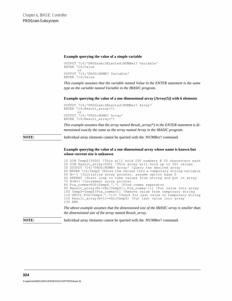
Chapter 6, IBASIC ControllerPROGram Subsystem
Example querying the value of a simple variable
OUTPUT 714;"PROGram:SELected:NUMBer? Variable"ENTER 714;Value
orOUTPUT 714;"PROG:NUMB? Variable"ENTER 714;Value
This example assumes that the variable named Value in the ENTER statement is the sametype as the variable named Variable in the IBASIC program.
Example querying the value of a one dimensional array [Array(5)] with 6 elements
OUTPUT 714;"PROGram:SELected:NUMBer? Array"ENTER 714;Result_array(*)
orOUTPUT 714;"PROG:NUMB? Array"ENTER 714;Result_array(*)
This example assumes that the array named Result_array(*) in the ENTER statement is di-mensioned exactly the same as the array named Array in the IBASIC program.
NOTE: Individual array elements cannot be queried with the :NUMBer? command.
Example querying the value of a one dimensional array whose name is known but whose current size is unknown
10 DIM Temp$[5000] !This will hold 250 numbers @ 20 characters each20 DIM Result_array(500) !This array will hold up to 501 values30 OUTPUT 714;"PROG:NUMB? Array" !Query the desired array40 ENTER 714;Temp$ !Enter the values into a temporary string variable50 N=-1 !Initialize array pointer, assume option base 060 REPEAT !Start loop to take values from string and put in array70 N=N+1 !Increment array pointer80 Pos_comma=POS(Temp$,",") !Find comma separator90 Result_array(N)=VAL(Temp$[1,Pos_comma-1]) !Put value into array100 Temp$=Temp$[Pos_comma+1] !Remove value from temporary string110 UNTIL POS(Temp$,",")=0 !Check for last value in temporary string120 Result_array(N+1)=VAL(Temp$) !Put last value into array130 END
The above example assumes that the dimensioned size of the IBASIC array is smaller thanthe dimensioned size of the array named Result_array.
NOTE: Individual array elements cannot be queried with the :NUMBer? command.
324
S:\agilent\e8285\USRGUIDE\BOOK\CHAPTERS\ibasic.fb

Chapter 6, IBASIC ControllerPROGram Subsystem
:STATe RUN|PAUSe|STOP|CONTinue The STATe command is used to set, from an external controller, the execution state of the IBASIC program in the Test Set. Table 35 defines the effect of setting the execution state of the IBASIC program to a desired state from each of the possible current states.
The program execution states are defined as follows:
• RUNNING, the program is currently executing.• PAUSED, the program has reached a break in execution but can be continued.• STOPPED, program execution has been terminated.
Syntax
PROGram[:SELected]:STATe RUN|PAUSe|STOP|CONTinue
Example
OUTPUT 714;"PROGram:SELected:STATe RUN"or
OUTPUT 714;"PROG:STAT RUN"
Table 35 Effect of STATe Commands
Desired State of IBASIC Program(STATe command sent
to Test Set)
Current State of IBASIC Program
RUNNING PAUSED STOPPED
RUN GPIB Error: -221 Settings conflict
RUNNING RUNNING
CONT GPIB Error: -221 Settings conflict
RUNNING GPIB Error: -221 Settings conflict
PAUSE PAUSED PAUSED STOPPED
STOP STOPPED STOPPED STOPPED
325

Chapter 6, IBASIC ControllerPROGram Subsystem
:STATe? The STATe? query command is used to query, from an external controller, the current execution state of the IBASIC program in the Test Set. The return data (RUN, STOP, or PAUS) is sent as a series of ASCII characters.
The program execution states are defined as follows:
• RUN, the program is currently executing.• PAUS, the program has reached a break in execution but can be continued.• STOP, program execution has been terminated.
Syntax
PROGram[:SELected]:STATe?
Example
OUTPUT 714;"PROGram:SELected:STATe?"ENTER 714;State$
orOUTPUT 714;"PROG:STAT?"ENTER 714;State$
326
S:\agilent\e8285\USRGUIDE\BOOK\CHAPTERS\ibasic.fb

Chapter 6, IBASIC ControllerPROGram Subsystem
ringsed in
ut
:STRing <varname>{,<svalues>} The :STRing command is used to set, from an external controller, the value of string variables or string arrays in an IBASIC program in the Test Set. <varname> is the name of an existing string variable or string array in the IBASIC program. <svalues> is a list of comma-separated quoted strings which are used to set the value of <varname>.
NOTE: If the variable name <var_name> is longer than 12 characters it must be sent as string data(<var_name> enclosed in quotes). For example, OUTPUT 714;"PROG:STR’Var_name’,’data’".
Attempting to send a <var_name> longer than 12 characters as character data(<var_name> not enclosed in quotes) will generate the following error:GPIBError: -112 Program mnemonic too long
NOTE: If the programmer wishes to append the IBASIC “$” string identifier onto the stvariable name, the string variable name must be sent as string data, that is encloquotes. For example,OUTPUT 714;"PROG:STR 'Var_name$','data'"
Appending the IBASIC “$” string identifier onto the string variable name withoenclosing the string variable name in quotes will generateGPIB Error: -101 Invalid character.
If an attempt is made to set the value of a string variable or array and no IBASIC program is in the Test Set an IBASIC Error: -282 Illegal program name is generated. If an attempt is made to set the value of a string variable or array and the string variable specified in <varname> does not exist in the program an IBASIC Error: -283 Illegal variable name is generated. If a quoted string value is too long to fit into the string variable then it is silently truncated when stored into the IBASIC string variable. If the specified string variable cannot hold all of the quoted strings an IBASIC Error: -108 Parameter not allowed is generated.
327

Chapter 6, IBASIC ControllerPROGram Subsystem
abletes. For
ing
Syntax
PROGram[:SELected]:STRing <varname>{,<svalues>}
Example setting the value of a simple string variable
OUTPUT 714;"PROGram:SELected:STRing Variable,’data’"or
OUTPUT 714;"PROG:STR Variable,’data’"
Example of setting the value of a string array with 3 elements of 5 characters each, such as Array$(2)[5]
OUTPUT 714;"PROGram:SELected:STRing Array,’12345’,’12345’,’12345’"or
OUTPUT 714;"PROG:STR Array,’12345’,’12345’,’12345’"
Note: With Option Base 0 set in IBASIC, array indexing starts at 0.
:STRing? <varname> The :STRing? query command is used to return, to an external controller, the current value of string variables or arrays in an IBASIC program in the Test Set . <varname> is the name of an existing string variable or string array in the IBASIC program.
NOTE: If the variable name <var_name> is longer than 12 characters it must be sent as string data(<var_name> enclosed in quotes). For example, OUTPUT 714;"PROG:STR? ’Var_name’".
Attempting to send a <var_name> longer than 12 characters as character data (<var_name>not enclosed in quotes) will generate the following error:
GPIB Error: -112 Program mnemonic too long
If the programmer wishes to append the IBASIC ‘$’ string identifier onto the string variname, the string variable name must be sent as string data, that is enclosed in quoexample,OUTPUT 714;"PROG:STR? 'Var_name$'"
Appending the IBASIC ‘$’ string identifier onto the string variable name without enclosthe string variable name in quotes will generate the following error
GPIB Error: -101 Invalid character
328
S:\agilent\e8285\USRGUIDE\BOOK\CHAPTERS\ibasic.fb

Chapter 6, IBASIC ControllerPROGram Subsystem
n list of tc.).
ring st in
For simple string variables the value is returned as a quoted string (“This is aexample.”). For string arrays the values are returned as a comma separated quoted strings (“This is an example.”,“This is an example.”). The string arrayelements are returned in ascending order (Array$(0), Array$(1), Array$(2), e
If an attempt is made to query the value of a string variable or array and no IBASIC program is in the Test Set an IBASIC Error: -283 Illegal variable name is generated. If an attempt is made to query the value of a stvariable or array and the string variable specified in <varname> does not exithe program an IBASIC Error: -283 Illegal variable name is generated.
Syntax
PROGram[:SELected]:STRing? <varname>
NOTE: The program commands and syntax used to enter string data from the Test Set into theexternal controller will depend upon the programming language used in the externalcontroller. The examples which follow represent the capabilities of HP® Rocky MountainBASIC programming language running on an HP® 9000/300 Series Controller.
329

Chapter 6, IBASIC ControllerPROGram Subsystem
Example of querying the value of a simple string variable
OUTPUT 714;"PROGram:SELected:STRing? Variable"ENTER 714;Value$
orOUTPUT 714;"PROG:STR? Variable"ENTER 714;Value$
Example of querying the value of a string array with 3 elements of 5 characters each, such as Array$(2)[5]
OUTPUT 714;"PROGram:SELected:STRing? Array"ENTER 714 USING "3(X,5A,2X)";Result_array$(*)
orOUTPUT 714;"PROG:STR? Array"ENTER 714 USING "3(X,5A,2X)";Result_array$(*)
This example assumes that the string array named Result_array$(*) is dimensioned exactlythe same as the array named Array in the IBASIC program and that each element in thestring array Array has five characters in it.
Example of querying the value of a string array whose name is known but whose cur-rent size is unknown
05 OPTION BASE 110 DIM Temp$[5000] !This will hold 5000 characters20 DIM Temp_array$(50)[200]!Temp array: 50 elements of 200 character30 OUTPUT 714;"PROG:STR? Array" !Query the desired array40 ENTER 714;Temp$ !Enter the values into a temporary string variable50 N=0 !Initialize array pointer60 REPEAT !Start loop to take values from string and put in array70 N=N+1 !Increment array pointer80 Pos_comma=POS(Temp$,",") !Find comma separator90 Temp_array$(N)=Temp$[2,Pos_comma-2] !Put value into array100 Temp$=Temp$[Pos_comma+1] !Remove value from temporary string110 UNTIL POS(Temp$,",")=0 !Check for last value in temporary string120 Temp_array$(N+1)=Temp$[2,LEN(Temp$)-1]!Put last value in array130 END
The above example assumes that the total number of characters in the dimensionedsize of the IBASIC string array named Array is smaller than the dimensioned sizeof the string variable named Temp$. Also, the maximum length of any element inthe IBASIC string array Array must be less than or equal to 200 characters.
330
S:\agilent\e8285\USRGUIDE\BOOK\CHAPTERS\ibasic.fb

Chapter 6, IBASIC ControllerPROGram Subsystem
:WAIT The :WAIT command stops the Test Set from executing any commands or queries received through GPIB until after the IBASIC program exits the RUN state; that is, the program is either PAUSED or STOPPED.
CAUTION: The Test Set will continue to process GPIB commands into the GPIB input buffer up to the point that the buffer is full. If the external controller attempts to send more commands than can fit into the GPIB input buffer before the IBASIC program is PAUSED or STOPPED, the GPIB bus will appear to be locked up. This is due to the fact that the GPIB bus and the external controller will be in a temporary holdoff state while waiting for the GPIB input buffer to empty.
If a query command is sent to the Test Set while the IBASIC program is under theinfluence of a :WAIT command, no data will be put into the Test Set’s OutputQueue until the IBASIC program is either PAUSED or STOPPED. If the externalcontroller attempts to enter the queried data before the IBASIC program isPAUSED or STOPPED, the GPIB bus will appear to be locked up. This is due tothe fact that the GPIB bus and the external controller will be in a temporaryholdoff state while waiting for the data to be put into the Output queue to satisfythe enter command.
Syntax
PROGram[:SELected]:WAIT
Example
OUTPUT 714;"PROGram:SELected:WAIT"or
OUTPUT 714;"PROG:WAIT"
331
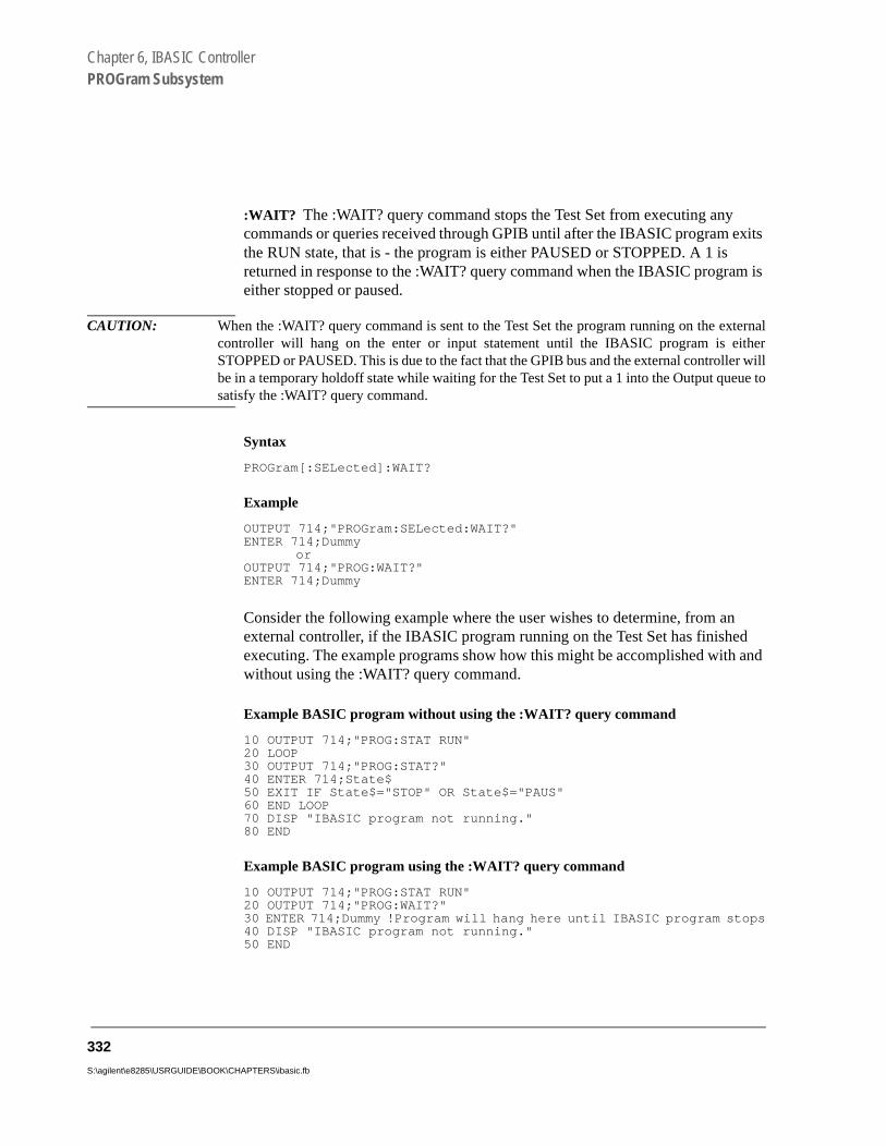
Chapter 6, IBASIC ControllerPROGram Subsystem
:WAIT? The :WAIT? query command stops the Test Set from executing any commands or queries received through GPIB until after the IBASIC program exits the RUN state, that is - the program is either PAUSED or STOPPED. A 1 is returned in response to the :WAIT? query command when the IBASIC program is either stopped or paused.
CAUTION: When the :WAIT? query command is sent to the Test Set the program running on the externalcontroller will hang on the enter or input statement until the IBASIC program is eitherSTOPPED or PAUSED. This is due to the fact that the GPIB bus and the external controller willbe in a temporary holdoff state while waiting for the Test Set to put a 1 into the Output queue tosatisfy the :WAIT? query command.
Syntax
PROGram[:SELected]:WAIT?
Example
OUTPUT 714;"PROGram:SELected:WAIT?"ENTER 714;Dummy
orOUTPUT 714;"PROG:WAIT?"ENTER 714;Dummy
Consider the following example where the user wishes to determine, from an external controller, if the IBASIC program running on the Test Set has finished executing. The example programs show how this might be accomplished with and without using the :WAIT? query command.
Example BASIC program without using the :WAIT? query command
10 OUTPUT 714;"PROG:STAT RUN"20 LOOP30 OUTPUT 714;"PROG:STAT?"40 ENTER 714;State$50 EXIT IF State$="STOP" OR State$="PAUS"60 END LOOP70 DISP "IBASIC program not running."80 END
Example BASIC program using the :WAIT? query command
10 OUTPUT 714;"PROG:STAT RUN"20 OUTPUT 714;"PROG:WAIT?"30 ENTER 714;Dummy !Program will hang here until IBASIC program stops40 DISP "IBASIC program not running."50 END
332
S:\agilent\e8285\USRGUIDE\BOOK\CHAPTERS\ibasic.fb

Chapter 6, IBASIC ControllerPROGram Subsystem
Using the EXECute Command
The PROGram:EXECute command can be used to list, edit and control IBASIC programs in the Test Set from an external controller. This eliminates having to use the cursor control knob and provides a more efficient way of making small changes to programs. The full range of IBASIC program commands can be executed from an external controller using the PROGram:EXECute command.
The following operations are given as typical examples of using the PROGram:EXECute command.
NOTE: The program commands and syntax used to send data from the external controller to theTest Set will depend upon the programming language used in the external controller. Theexamples which follow represent the capabilities of HP® Rocky Mountain BASICprogramming language running on an HP® 9000/300 Series Controller.
When a PROGram Subsystem command is sent to the Test Set through GPIBfrom an external controller the Test Set is put into REMOTE mode. The Test Setmust be put in LOCAL mode to use the front panel keys or to use the serial portsto input data into the IBASIC Command line.
333

Chapter 6, IBASIC ControllerPROGram Subsystem
ry,
uotes.
ory
e
Entering a new IBASIC program line
IBASIC program lines can be entered directly into the Test Set’s RAM memoone line at a time, from an external controller using the PROGram:EXECute command as follows:
PROG:EXEC ’<new program line number/program line>’
where <new program line number/program line> represents a valid IBASIC program line.
For example, to enter the following new program line into the Test Set,
20 A=3.14
execute the following command from the external controller:
OUTPUT 714;"PROG:EXEC ’20 A=3.14’"
Quoted strings, such as those used in PRINT commands, must use double qFor example,
OUTPUT 714;"PROG:EXEC ’30 PRINT ""TEST""’"
Editing an existing IBASIC program line
Existing IBASIC program lines which are resident in the Test Set’s RAM memcan be edited, one line at a time, from an external controller using the PROGram:EXECute command as follows:
PROG:EXEC ’<existing program line number/modified program line>’
where <existing program line number/modified program line> represents an existing IBASIC program line.
For example, to edit the following existing program line in the Test Set.
30 OUTPUT 814;"AFAN:DEMP:GAIN 20 dB"
to30 OUTPUT 814;"AFAN:DEMP:GAIN 10 dB"
execute the following command from the external controller:
OUTPUT 714;"PROG:EXEC ’30 OUTPUT 814;""AFAN:DEMP:GAIN 10 dB""’"
Quoted strings, such as those used in OUTPUT commands, must use doublquotes.
334
S:\agilent\e8285\USRGUIDE\BOOK\CHAPTERS\ibasic.fb

Chapter 6, IBASIC ControllerPROGram Subsystem
sr is an
pro-
dure
the
n.
el of l-
Listing A Program
Execute the following command on the external controller to list an IBASIC program which is resident in the Test Set to the currently specified IBASIC Controller LIST device.
OUTPUT 714;"PROG:EXEC ’LIST’"
Downloading An IBASIC Program Into the Test Set
The following procedure uses the PROGram Subsystem commands to transfer an IBASIC program, which is resident in the memory of the external controller, from the external controller to the Test Set. This procedure assumes the Test Set’GPIB address is set to 14. The example also assumes the external controlleHP® 9000 Series 300 Controller.
1. Access the Test Set’s TESTS (IBASIC Controller) screen.
2. Enter a program into the external controller. Use the sample program below if nogram is available. When run, the sample program clears the Test Set’s IBASIC Controller display area, and prints a message indicating that the download proceworked.
10 !THIS IS A SAMPLE PROGRAM20 CLEAR SCREEN30 PRINT "DOWNLOADING COMPLETED"40 END
3. Execute the following commands on the external controller:
OUTPUT 714;"PROG:DEL:ALL"OUTPUT 714;"PROG:DEF #0"LIST #714OUTPUT 714;" "END
4. To verify that the program was downloaded, execute the following commands fromexternal controller:
OUTPUT 714;"PROG:EXEC ’LIST’"
The program should be listed on the Test Set’s TESTS (IBASIC Controller) scree
5. Run the program on the Test Set by first selecting the Local key on the front panthe Test Set and then selecting the Run key on the Test Set’s TESTS (IBASIC Controler) screen.
335

Chapter 6, IBASIC ControllerPROGram Subsystem
n
As , and
Uploading a Program From the Test Set
The following BASIC program copies an IBASIC program from the Test Set’sIBASIC Controller RAM to the external controller and then stores it to a file othe external controller’s currently assigned mass storage device.
When the upload program is entered and run on the external controller, the operator is prompted for the name of the file to store the IBASIC program in.the upload program is running, the total number of characters in the programthe number of characters transferred, are displayed.
10 !Upload an IBASIC program in Test Set to an external controller.20 DIM Prog_line$[200] !Holds longest program line in Test Set30 DIM File_name$[10] !Holds the name of file to store IBASIC program40 Addr=714 !Test Set GPIB address50 LINPUT "Enter name of file to store IBASIC program in:",File_name$60 OUTPUT Addr;"PROG:DEF?"70 ENTER Addr USING "X,D,#";Count_length !Get length of count field80 !Get number of characters in program, includes CR/LF on each line90 ENTER Addr USING VAL$(Count_length)&"D,#";Chars_total100 !Create ASCII file to hold program, add 5 records for buffer110 CREATE ASCII File_name$,(Chars_total/256)+5120 ASSIGN @File TO File_name$130 LOOP140 ENTER Addr;Prog_line$ !Read in one program line150 OUTPUT @File;Prog_line$ !Store in file160 Chars_xferd=Chars_xferd+LEN(Prog_line$)+2 !CR/LF not read170 DISP Chars_xferd;"of";Chars_total;"characters transferred."180 EXIT IF Chars_xferd>=Chars_total190 END LOOP200 ENTER Addr;Msg_terminator$ !Terminate the block data transfer210 ASSIGN @File TO * !Close the file220 END
336
S:\agilent\e8285\USRGUIDE\BOOK\CHAPTERS\ibasic.fb
Chapter 6, IBASIC ControllerPROGram Subsystem
nel
Saving an IBASIC Program To A Memory Card
The following procedure can be used to save an IBASIC program from the IBASIC Controller’s RAM memory to a memory card inserted into the front paof the Test Set.
1. Press LOCAL, SHIFT, CANCEL on the Test Set to perform an IBASIC reset.
2. If the memory card has not been initialized, insert it into the Test Set and execute the following command on the external controller:
OUTPUT 714;"PROG:EXEC ’INITIALIZE""DOS:INTERNAL,4""’"
3. Insert the initialized memory card into the Test Set.
4. Define the memory card as the Mass Storage device by executing the following com-mand on the external controller:
OUTPUT 714;"PROG:EXEC ’MSI "":INTERNAL,4""’"
5. Save the program to the memory card by executing the following command on the ex-ternal controller:
OUTPUT 714;"PROG:EXEC ’SAVE ""<filename>""’"
337
Chapter 6, IBASIC ControllerThe TESTS Subsystem
gilent t Set.
the o the radio ns to for a
The TESTS Subsystem
The Test Set makes available to the user an automated user-interface which has been specifically designed for radio test. One of the primary problems associated with automated radio testing is the need to rapidly configure the software with the information needed to test a specific type of radio. Information such as, test frequencies/channels, test specifications, test parameters, test conditions and pass/fail limits. Most often the test(s) and test procedure(s) used to test a class of radio (AM, FM, AMPS, TACS, TDMA, CDMA, etc.) are defined by an industry standard and are used to test all radio types within that class. However, for a specific radio type, the test(s) may remain the same but the information needed to test the radio changes. For example, a portable hand-held may have different transmit power levels than a mobile - the RF power test is the same but the power levels, supply voltages, pass/fail limits etc. can be different.
There are two approaches which can be used to provide the software with the information needed to test a radio: a) hardcode the information directly into the software, or b) store the information outside the program code itself and make it available to the software as needed. Hardcoding the information into the software has several serious drawbacks: changing the information is difficult and the software becomes specific to that radio type. Storing the information outside the program code and making it available to the software as needed overcomes both of these problems, that is - the information is easy to change and the software is not specific to a particular type of radio.
The Test Set’s automated user-interface was designed using this approach. ATechnologies has developed software specifically designed to run on the TesThe Agilent Technologies 83217 Software provides the user with a library of industry standard tests. All radio specific information has been removed fromsoftware. The information needed to test a specific type of radio is available tuser through the TESTS Subsystem. To generate, change and maintain this specific information the TESTS Subsystem provides menu driven input screedefine specifications, parameters, test sequencing and system configurationparticular radio type.
338
S:\agilent\e8285\USRGUIDE\BOOK\CHAPTERS\ibasic.fb

Chapter 6, IBASIC ControllerThe TESTS Subsystem
TESTS Subsystem File Descriptions
Three types of files are used in the TESTS Subsystem to store different types of information.
Code Files
The first aspect of an automated definition is the code itself. This is just a standard IBASIC Code file that can reside either on the Memory card, on an external disk drive connected to the GPIB port of the Test Set, or in an internal RAM disk. The name of this file is appended with .PGM file extension. This tells the TESTS Subsystem that this particular file contains program code.
Library Files
A Library indicates all of the available test subroutines in the code, the set of all parameters that might be entered using the user-interface screens, and all specifications that might be used by the subroutines in the code to decide if a test point passes or fails.
Only one Library is defined for each Code file. The name of this file is appended with a .LIB file extension, telling the TESTS system that this is a Library file. Also, both the Library and Code file should have the same base name to indicate the relationship between them.
A Library is required to use the user-interface screen functions of the TESTS Subsystem. If the program is simple enough that there is no need for user-input, or if all the user-input is simple enough to be accomplished with INPUT statements, a [NO LIB] option is available.
Procedure Files
A Procedure allows the user to define which of the test subroutines, parameters, and specifications defined in the Library will be used to test a specific Radio. There may be many Procedures defined that use the same IBASIC Code and Library, each using a different subset of the choices available in the Library. These files are appended with a .PRC file extension, but are not required to have the same base name as either the Library or the Code. The name of the corresponding Library (if any) is stored in each Procedure file.
339

Chapter 6, IBASIC ControllerThe TESTS Subsystem
Figure 42 TESTS Subsystem File Relationship
IBASIC Test CodecName
Code for all possibleradio tests
Test LibrarylName
Set of all parameters,specifications, and
tests
Procedure 1pName
Parameters,Specifications, andtest for each radio
Procedure 2pName2
Procedure NpNameN
ch6drw06.drw
340
S:\agilent\e8285\USRGUIDE\BOOK\CHAPTERS\ibasic.fb

Chapter 6, IBASIC ControllerThe TESTS Subsystem
TESTS Subsystem Screens
The TESTS Subsystem uses several screens to create, select, and copy files, and to run tests.
The TESTS (Main Menu) Subsystem Screen
The TESTS (Main Menu) screen is accessed by pressing the front panel Tests key. Test procedures are selected and run from this screen. Additionally, access to all other TESTS Subsystem screens is accomplished from this screen.
Figure 43 The TESTS (Main Menu) Subsystem Screen
341

Chapter 6, IBASIC ControllerThe TESTS Subsystem
vail-
for
es-
s to r sup-
nd
-
di-
The Select Procedure Location: field is used to select the mass storage location for the procedure to be loaded. The Select Procedure Filename: field is used to select the name of the procedure to be loaded. The Description: field gives the user a brief description of the procedure currently selected in the Select Procedure Filename: field.
To view all the Procedures available on the mass storage location currently selected in the Select Procedure Location: field, position the cursor on the Select Procedure Filename: field and push the rotary knob. A menu will appear in the lower right corner of the screen, displaying all the procedure files which are available. This is not a listing of the full contents of the selected mass storage location, it is only a list of the procedures files that are stored on that media.
TESTS Subsystem User-Interface Screens
The TESTS Subsystem allows the user to easily modify the test subroutines, parameters, specifications and configuration to correspond to the requirements of a specific radio. There are several user-interface screens provided to allow the user to make modifications.
To access any of these screens, position the cursor on the desired field and push the rotary knob.
• The Order of Tests screen lets the user select the desired test(s) from the full set of aable tests in the loaded procedure file.
• The Channel Information screen defines the transmit and receive frequencies usedthe selected tests.
• The Pass/Fail Limits screen defines the specifications used to generate pass/fail msages during testing.
• The Test Parameters screen is used to define instrument settings and characteristicmatch those of the radio being tested (audio load impedance, audio power, poweply voltage, etc.).
• The External Devices screen identifies all connected GPIB equipped instruments atheir GPIB addresses.
• The Save/Delete Procedure screen is used to save or delete Procedures.
• The Printer Setup screen is used to select the printer used for IBASIC PRINT commands and to configure the format of the printer page.
• The Execution Cond screen is used to configure the IBASIC program execution contions.
• The IBASIC Cntrl screen is the IBASIC Controllers display screen.
342
S:\agilent\e8285\USRGUIDE\BOOK\CHAPTERS\ibasic.fb
Chapter 6, IBASIC ControllerThe TESTS Subsystem
Refer to the TESTS Screen chapter for descriptions in the Agilent Technologies E8285A Reference Guide for information concerning how the different TESTS Subsystem screens are used.
The use of the IBASIC Controller screen is described in the beginning of this chapter.
343

Chapter 6, IBASIC ControllerThe TESTS Subsystem
344
S:\agilent\e8285\USRGUIDE\BOOK\CHAPTERS\ibasic.fb

A
Error Messages
345

Error Messages
"General Information About Error Messages" on page 347"Positive Numbered Error Messages" on page 348"IBASIC Error Messages" on page 349"GPIB Error Messages" on page 350"Text Only Error Messages" on page 351"The Message Display" on page 352"Non-Recoverable Firmware Error" on page 353"Text Only GPIB Error Descriptions" on page 355"Numbered GPIB Error Descriptions" on page 357"List of Text Only Error Messages" on page 374
346
S:\agilent\e8285\USRGUIDE\BOOK\CHAPTERS\errorms.fb

Error Messages
General Information About Error Messages
Information concerning error messages displayed by the Test Set may be found in one of the following manuals:
• This section• The HP® Instrument BASIC Users Handbook Version 2.0 (HP® P/N E2083-90005)
The format of the displayed message determines which manual contains information about the error message. There are four basic error message formats:
• Positive numbered error messages • IBASIC error messages • GPIB error messages • Text only error messages
347

Error Messages
Positive Numbered Error Messages
Positive numbered error messages are generally associated with IBASIC. Refer to the
HP® Instrument BASIC User’s Handbook for information on IBASIC error messages.
Positive numbered error messages take the form: ERROR XX Message Text
For example:
• Error 54 Duplicate file name
• or
• Error 80 in 632 Medium changed or not in drive
348
S:\agilent\e8285\USRGUIDE\BOOK\CHAPTERS\errorms.fb

Error Messages
IBASIC Error Messages
IBASIC Error Messages are associated with IBASIC operation. IBASIC error messages
can have both positive and negative numbers. Refer to the HP® Instrument BASIC User’s Handbook for information on positive numbered error messages. Refer to "GPIB Error Messages" on page 350 for information on negative numbered error messages (the error message associated with a negative number is the same for GPIB errors and IBASIC errors).
IBASIC error messages take the form: IBASIC Error: -XX Message Text
For example:
• IBASIC Error: -286 Program runtime error
349
Error Messages
GPIB Error Messages
Most GPIB errors occur when the control program attempts to query a measurement that is not currently available, or tries to access an instrument connected to the external GPIB without configuring the Test Set as the System Controller. When diagnosing the cause of an error condition check for these conditions first.
Refer to "Text Only GPIB Error Descriptions" on page 355 or "Numbered GPIB Error Descriptions" on page 357 for a list of some of the common error messages.
GPIB error messages take the form:GPIB Error: -XX Message Text or GPIB Error: Message Text
For example:
GPIB Error: -410 Query INTERRUPTED.
or
GPIB Error: Input value out of range.
350
S:\agilent\e8285\USRGUIDE\BOOK\CHAPTERS\errorms.fb

Error Messages
g
Text Only Error Messages
Text only error messages are generally associated with manual operation of the Test Set. See "The Message Display" on page 352 for more information about messages displayed on the Test Set’s display.
Un-numbered (text only) GPIB error messages are generally self-explanatory. For example, trying to retrieve a saved register that does not exist generates the followinerror message:
GPIB Error: Register does not exist.
Text only error messages can also be displayed while running the Test Set’s built-in diagnostic or calibration utility programs.
Text only error messages take the form: This is an error message.
For example:
• Input value out of range.
351

Error Messages
y. neral e dition, only knob ed on
(turn d
The Message Display
During instrument operation, various messages may appear on the Test Set’s displaPrompt-type messages generally appear on the first line of the Test Set’s display. Geoperating and error messages usually appear on the second line of the display. Sommessages are persistent; they remain displayed, pending correction of the error conor until another persistent message with greater priority occurs. Other messages aredisplayed when the error first occurs; they are removed when a key is pressed or theis turned, or when an GPIB command is received. Many of the messages are displaythe MESSAGE screen until the instrument is turned off.
Messages that are about error conditions may tell you what to do to correct the errorsomething off, reduce a field’s value, press a certain key, and so forth). Messages anprompts are sometimes accompanied by a beep or warble.
NOTE: Warbles and Beeps
A warble sound indicates that an instrument-damaging event is occurring. Beepsoften occur only with the first occurrence of the message. Prompts are generallysilent.
352
S:\agilent\e8285\USRGUIDE\BOOK\CHAPTERS\errorms.fb

Error Messages
dition ower or the
Non-Recoverable Firmware Error
This error, also referred to as an “assert” occurs when the Test Set encounters a conthat the firmware cannot proceed from - causing the Test Set to halt operation until pis cycled. The message appears in the center of the Test Set’s display and (except ftwo lines in the second paragraph) has the form:
Non-recoverable firmware error. Please record the 2 lines oftext below and contact Hewlett Packard through your localservice center. In the U.S., you may call the factory at
(800) 827-3848.
‘Address error exception’at line number 0
To continue operation, turn POWER off and back on.
Unfortunately, you will not be able to recover from this condition without turning the Test Set off. If the failure reoccurs when you attempt to repeat the operation that caused the failure in the first place, you should record exactly what the configuration of the instru-ment was when the error appeared, and contact Agilent Technologies. This information will help us determine the proper course of action for your repair.
353

Error Messages
his d; the tial-
If The Non-Recoverable Firmware Error Occurs at Power-up
If the Test Set displays this error when first powered up, disabling Test Set opera-tion, it could be related to the Autostart field on the main TESTS screen, or a POWERON Save/Recall register. This field causes the Test Set to automatically run the last program loaded in memory when the Test Set is powered up. If the pro-gram is corrupted, the Test Set will automatically “lock up”.
The only way to recover from this condition is to clear the Test Set’s operating RAM. Twill clear any IBASIC program, Save/Recall registers, and RAM disks that have beensaved, as well as three calibration factors. The calibration factors are easily re-entereIBASIC programs, Save/Recall registers, and RAM disks must be re-loaded or re-iniized after clearing memory.
To Clear the Test Set’s RAM:
1. Turn the Test Set off.2. Hold the PRESET and HZ/uV buttons down.3. Turn the power on (with the buttons still held down) and wait until the CDMA CALL
CONTROL screen is displayed.
Re-enter the Calibration Factors Erased when RAM is Cleared
Use this procedure to re-enter the three calibration factors that were erased when RAM is cleared. Use the ANLG SCRNS keys (to the left of the cursor control knob) to access the required screens.
1. Access the RF GENERATOR screen and select the DC FM Zero field (under FM Coupling).
2. Disconnect any cables to the ANT IN or RF IN/OUT connectors.3. Access the TX TEST screen and select Zero under the TX Pwr Zero field.4. Access the AF ANALYZER screen and select Zero under the DC Current field.
354
S:\agilent\e8285\USRGUIDE\BOOK\CHAPTERS\errorms.fb

Error Messages
hese error
rnal
t is not
Text Only GPIB Error Descriptions
The following list contains a subset of the Test Set’s text only GPIB error messages. Tmessages represent error conditions which may require explanation in addition to themessage text.
GPIB Error during Procedure catalog. Check Config.
This error occurs when the Test Set fails to access an external GPIB disk drive whentrying to obtain a catalog of procedure files. This would occur when the Select Procedure Location: field on the TESTS (Main Menu) screen is set to Disk and the operator then tries to select a procedure filename using the Select Procedure FIlename: field. Ensure that the Mode field on the I/O CONFIGURE screen is set to Control and that the External Disk Specification field on the TESTS (External Devices) screen has the correct mass storage volume specifier for the extedisk drive.
GPIB Query Error. Check instrument state.
This message usually appears when the control program queries a measurement thacurrently available (on the currently displayed screen and in the ON state), such as querying the TX Frequency measurement when TX Freq Error is displayed. This message may also be immediately followed by the message, GPIB Error: −420: Query UNTERMINATED.
355

Error Messages
tile
and
rage
ction ata er to
GPIB Error: Not Enough Memory Available for Save.
This message will be generated when the control program tries to save the current Test Set state into a Save/Recall register using the REG:SAVE commands, but there is insufficient memory available in the Test Set. The Test Set’s non-volatile RAM is shared by the following resources:
• IBASIC programs • Save/Recall registers • RAM Disk
In order to save the current Test Set state into a Save/Recall register more non-volaRAM will have to be made available. This can be done by,
• reducing the size of the IBASIC program • deleting one or more existing Save/Recall registers • recovering RAM Disk space
The ROM Disk utility RAM_USAGE will display the total amount of non-volatile RAMinstalled in the Test Set, the RAM Disk allocation, the Save/Recall register allocationthe amount of non-volatile RAM available to IBASIC.
GPIB Error: Unknown Save/Recall error.
This error can occur when you are trying to SAVE the instrument state to a mass stodevice with a LIF formatted media. The default file system is DOS. Refer to chapter 5, "Memory Cards/Mass Storage" for more information.
GPIB Error: GPIB Units cause invalid conversion of attr.
This error is generated when trying to change Attribute Units and one of the Data Funvalues is set to zero. If this error is encountered the programmer must change the DFunction settings to values that can be converted to the new units_of_measure. Ref"To Specify Units-of-Measure for GPIB Data Transfer" on page 56 for more details.
356
S:\agilent\e8285\USRGUIDE\BOOK\CHAPTERS\errorms.fb

Error Messages
n-
bus,
ternal
r ). For
s. It
e was
Numbered GPIB Error Descriptions
The following GPIB errors can be generated under any of the following conditions:
• controlling the Test Set with an IBASIC program running on the built-in IBASIC cotroller
• controlling GPIB devices/instruments, connected to the Test Set’s external GPIBwith an IBASIC program running on the built-in IBASIC controller
• controlling the Test Set with a program running on an external controller
• using the Test Set manually to print to an external GPIB printer
• using the Test Set manually to access procedure/library/code files stored on an exGPIB disk
The negative numbers which precede the error message text correspond to the erroconditions outlined in the Standard Commands for Programmable Instruments (SCPImore information on SCPI, order the following book,
A Beginner’s Guide to SCPI Addison-Wesley Publishing Company ISBN 0-201-56350-9.
NOTE: GPIB Parser. The term “Parser” is used in the following error message descriptionrefers to the Test Set’s GPIB command parser.
Error −100 Command error
This code indicates only that a Command Error as defined in IEEE 488.2, 11.5.1.1.4 has occurred.
Error −101 Invalid character
A syntactic element contains a character which is invalid for that type.
Error −102 Syntax error
An unrecognized command or data type was encountered; for example, a string valureceived when the device does not accept strings.
357

Error Messages
Error −103 Invalid separator
The parser was expecting a separator and encountered an illegal character. For example, the colon used to separate the FREQ and AMPL commands should be omitted in the following command:
RFG:FREQ 850 MHZ:;AMPL -35
Error −104 Data type error
The parser recognized a data element different than one allowed. For example, numeric or string data was expected but block data was encountered.
Error −105 GET not allowed
A Group Execute Trigger was received within a program message (see IEEE 488.2, 7.7).
Error −108 Parameter not allowed
More parameters were received than expected for the header. For example, the *ESE common command only accepts one parameter; receiving *ESE 36,1 is not allowed.
Error −109 Missing parameter
Fewer parameters were received than required for the header. For example, the *ESE common command requires one parameter; receiving *ESE is not allowed.
Error −110 Command header error
An error was detected in the header.
Error −111 Header separator error
A character which is not a legal header separator was encountered while parsing the header.
Error −112 Program mnemonic too long
The header contains more than twelve characters (see IEEE 488.2,7.6.1.4).
358
S:\agilent\e8285\USRGUIDE\BOOK\CHAPTERS\errorms.fb

Error Messages
uding
Error −113 Undefined header
The header is syntactically correct, but it is undefined for this specific device. For example, *XYZ is not defined for any device.
Error −114 Header suffix out of range
Indicates that a nonheader character has been encountered in what the parser expects is a header element.
Error −120 Numeric data error
This error, as well as errors −121 through −128, are generated when parsing a data element which appears to be numeric, including the nondecimal numeric types.
Error −121 Invalid character in number
An invalid character for the data type being parsed was encountered. For example, an alpha in a decimal numeric or a “9” in octal data.
Error −123 Exponent too large
The magnitude of the exponent was larger than 32000 (see IEEE 488.2, 7.7.2.4.1).
Error −124 Too many digits
The mantissa of a decimal numeric data element contained more than 255 digits exclleading zeros (see IEEE 488.2, 7.7.2.4.1).
Error −128 Numeric data not allowed
A legal numeric data element was received, but the device does not accept one in this position for the header.
Error −130 Suffix error
This error, as well as errors −131 through −138, are generated when parsing a suffix.
Error −131 Invalid suffix
The suffix does not follow the syntax described in IEEE 488.2 7.7.3.2, or the suffix is inappropriate for this device.
359
Error Messages
Error −134 Suffix too long
The suffix contained more than 12 characters (see IEEE 488.2, 7.7.3.4).
Error −138 Suffix not allowed
A suffix was encountered after a numeric element which does not allow suffixes.
Error −140 Character data error
This error, as well as errors −141 through −148, are generated when parsing a character data element.
Error −141 Invalid character data
Either the character data element contains an invalid character or the particular element received is not valid for the header.
Error −144 Character data too long
The character data element contains more than twelve characters (see IEEE 488.2, 7.7.1.4).
Error −148 Character data not allowed
A legal character data element was encountered where prohibited by the device.
Error −150 String data error
This error, as well as errors −151 through −158, are generated when parsing a string element.
Error −151 Invalid string data
A string data element was expected, but was invalid for some reason (see IEEE 488.2, 7.7.5.2). For example, an END message was received before the terminal quote character.
Error −158 String data not allowed
A string data element was encountered but was not allowed by the device at this point in parsing.
360
S:\agilent\e8285\USRGUIDE\BOOK\CHAPTERS\errorms.fb
Error Messages
Error −160 Block data error
This error, as well as errors -161 through -168, are generated when parsing a block data element.
Error −161 Invalid block data
A block data element was expected, but was invalid for some reason (see IEEE 488.2 7.7.6.2). For example, an END message was received before the length was satisfied.
Error −168 Block data not allowed
A legal block data element was encountered but was not allowed by the device at this point in parsing.
Error −170 Expression error
This error, as well as errors -171 through -178, are generated when parsing an expression data element.
Error −171 Invalid expression
The expression data element was invalid (see IEEE 488.2, 7.7.7.2); for example, unmatched parentheses or an illegal character.
Error −178 Expression data not allowed
A legal expression data was encountered but was not allowed by the device at this point in parsing.
Error −180 Macro error
This error, as well as errors -181 through -184, are generated when defining a macro or executing a macro.
Error −181 Invalid outside macro definition
Indicates that a macro parameter placeholder was encountered outside of a macro definition.
361

Error Messages
Error −183 Invalid inside macro definition
Indicates that the program message unit sequence, sent with a *DDT or *DMC command, is syntactically invalid (see 10.7.6.3).
Error −184 Macro parameter error
Indicates that a command inside the macro definition had the wrong number or type of parameters.
Error −200 Execution error
This code indicates only that an Execution Error as defined in IEEE 488.2, 11.5.1.1.5 has occurred.
Error −201 Invalid while in local
Indicates that a command is not executable while the device is in local due to a hard local control (see IEEE 488.2, 5.6.1.5). For example, a device with a rotary switch receives a message which would change the switches state, but the device is in local so the message can not be executed.
Error −202 Settings lost due to rtl
Indicates that a setting associated with a hard local control (see IEEE 488.2, 5.6.1.5) was lost when the device changed to LOCS from REMS or to LWLS from RWLS.
362
S:\agilent\e8285\USRGUIDE\BOOK\CHAPTERS\errorms.fb

Error Messages
Error −210 Trigger error
Error −211 Trigger ignored
Indicates that a GET, *TRG, or triggering signal was received and recognized by the device but was ignored because of device timing considerations. For example, the device was not ready to respond.
Error −212 Arm ignored
Indicates that an arming signal was received and recognized by the device but was ignored.
Error −213 Init ignored
Indicates that a request for a measurement initiation was ignored as another measurement was already in progress.
Error −214 Trigger deadlock
Indicates that the trigger source for the initiation of a measurement is set to GET and subsequent measurement query is received. The measurement cannot be started until a GET is received, but the GET would cause an INTERRUPTED error.
Error −215 Arm deadlock
Indicates that the arm source for the initiation of a measurement is set to GET and subsequent measurement query is received. The measurement cannot be started until a GET is received, but the GET would cause an INTERRUPTED error.
Error −220 Parameter error
Indicates that a program data element related error occurred.
Error −221 Settings conflict
Indicates that a legal program data element was parsed but could not be executed due to the current device state (see IEEE 488.2, 6.4.5.3 and 11.5.1.1.5).
363

Error Messages
Error −222 Data out of range
Indicates that a legal program data element was parsed but could not be executed because the interpreted value was outside the legal range as defined by the device (see IEEE 488.2, 11.5.1.1.5).
Error −223 Too much data
Indicates that a legal program data element of block, expression, or string type was received that contained more data than the device could handle due to memory or related device- specific requirements.
Error −224 Illegal parameter value
Used where exact value, from a list of possibles, was expected.
Error −230 Data corrupt or stale
Possibly invalid data; new reading started but not completed since last access.
Error −231 Data questionable
Indicates that measurement accuracy is suspect.
Error −240 Hardware error
Indicates that a legal program command or query could not be executed because of a hardware problem in the device.
Error −241 Hardware missing
Indicates that a legal program command or query could not be executed because of missing device hardware. For example, an option was not installed.
Error −250 Mass storage error
Indicates that a mass storage error occurred.
364
S:\agilent\e8285\USRGUIDE\BOOK\CHAPTERS\errorms.fb
Error Messages
Error −251 Missing mass storage
Indicates that a legal program command or query could not be executed because of missing mass storage. For example, an option that was not installed.
Error −252 Missing media
Indicates that a legal program command or query could not be executed because of a missing media. For example, no disk.
Error −253 Corrupt media
Indicates that a legal program command or query could not be executed because of corrupt media. For example, bad disk or wrong format.
Error −254 Media full
Indicates that a legal program command or query could not be executed because the media was full. For example, there is no room on the disk.
Error −255 Directory full
Indicates that a legal program command or query could not be executed because the media directory was full.
Error −256 File name not found
Indicates that a legal program command or query could not be executed because the file name on the device media was not found. For example, an attempt was made to read or copy a nonexistent file.
Error −257 File name error
Indicates that a legal program command or query could not be executed because the file name on the device media was in error. For example, an attempt was made to copy to a duplicate file name.
Error −258 Media protected
Indicates that a legal program command or query could not be executed because the media was protected. For example, the write-protect switch on a memory card was set.
365

Error Messages
Error −260 Expression error
Indicates that an expression program data element related error occurred.
Error −261 Math error in expression
Indicates that a syntactically legal expression program data element could not be executed due to a math error. For example, a divide-by-zero was attempted.
Error −270 Macro error
Indicates that a macro-related execution error occurred.
Error −271 Macro syntax error
Indicates that a syntactically legal macro program data sequence, according to IEEE 488.2, 10.7.2, could not be executed due to a syntax error within the macro definition (see IEEE 488.2, 10.7.6.3).
Error −272 Macro execution error
Indicates that a syntactically legal macro program data sequence could not be executed due to some error in the macro definition (see IEEE 488.2, 10.7.6.3).
Error −273 Illegal macro label
Indicates that the macro label defined in the *DMC command was a legal string syntax, but could not be accepted by the device (see IEEE 488.2, 10.7.3 and 10.7.6.2). For example, the label was too long, the same as a common command header, or contained invalid header syntax.
Error −274 Macro parameter error
Indicates that the macro definition improperly used a macro parameter placeholder (see IEEE 488.2, 10.7.3).
366
S:\agilent\e8285\USRGUIDE\BOOK\CHAPTERS\errorms.fb

Error Messages
Error −275 Macro definition too long
Indicates that a syntactically legal macro program data sequence could not be executed because the string of block contents were too long for the device to handle (see IEEE 488.2, 10.7.6.1).
Error −276 Macro recursion error
Indicates that a syntactically legal macro program data sequence could not be executed because the device found it to be recursive (see IEEE 488.2 10.7.6.6).
Error −277 Macro redefinition not allowed
Indicates that syntactically legal macro label in the *DMC command could not be executed because the macro label was already defined (see IEEE 488.2, 10.7.6.4).
Error −278 Macro header not found
Indicates that a syntactically legal macro label in the *GMC? query could not be executed because the header was not previously defined.
Error −280 Program error
Indicates that a downloaded program-related execution error occurred.
Error −281 Cannot create program
Indicates that an attempt to create a program was unsuccessful. A reason for the failure might include not enough memory.
Error −282 Illegal program name
The name used to reference a program was invalid. For example, redefining an existing program, deleting a nonexistent program, or in general, referencing a nonexistent program.
Error −283 Illegal variable name
An attempt was made to reference a nonexistent variable in a program.
367

Error Messages
Error −284 Program currently running
Certain operations dealing with programs are illegal while the program is running. For example, deleting a running program is not possible.
Error −285 Program syntax error
Indicates that syntax error appears in a downloaded program.
Error −286 Program runtime error
Error −300 Device-specific error
This code indicates only that a Device-Dependent Error as defined in IEEE 488.2, 11.5.1.1.6 has occurred.
Error −310 System error
Indicates that some error, termed “system error” by the device, has occurred.
Error −311 Memory error
Indicates that an error was detected in the device’s memory.
Error −312 PUD memory lost
Indicates that the protected user data saved by the *PUD command has been lost.
Error −313 Calibration memory lost
Indicates that nonvolatile calibration data used by the *CAL? command has been lost.
Error −314 Save/recall memory lost
Indicates that the nonvolatile data saved by the *SAV command has been lost.
Error −315 Configuration memory lost
Indicates that nonvolatile configuration data saved by the device has been lost.
368
S:\agilent\e8285\USRGUIDE\BOOK\CHAPTERS\errorms.fb

Error Messages
Error −330 Self-test failed
Error −350 Queue overflow
This code indicates that there is no room in the queue and an error occurred but was not recorded. This code is entered into the queue in lieu of the code that caused the error.
Error −400 Query error
This code indicates only that a Query Error as defined in IEEE 488.2 11.5.1.1.7 and 6.3 has occurred.
Error −410 Query INTERRUPTED
Indicates that a condition causing an INTERRUPTED Query error occurred (see IEEE 488.2, 6.3.2.3). For example, a query followed by DAB or GET before a response was completely sent.
This message appears when you query a measurement without immediately entering the returned value into a variable. For example, the following program lines query the TX Frequency measurement and enter its value into a variable (Rf_freq):
OUTPUT 714;"MEAS:RFR:FREQ:ABS?"ENTER 714;Rf_freq
Error −420 Query UNTERMINATED
Indicates that a condition causing an UNTERMINATED Query error occurred (see IEEE 488.2, 6.3.2.2.). For example, the device was addressed to talk and an incomplete program message was received.
This message usually appears when trying to access a measurement that is not active. For example, you cannot query the DTMF Decoder measurements from the DUPLEX TEST screen, or query the TX Frequency measurement when the TX Freq Error measurement is displayed.
Error −430 Query DEADLOCKED
Indicates that a condition causing a DEADLOCKED Query error occurred (see IEEE 488.2, 6.3.1.7). For example, both input buffer and output buffer are full and the device cannot continue.
369

Error Messages
Error −440 Query UNTERMINATED after indefinite response
Indicates that a query was received in the same program message after a query requesting an indefinite response was executed (see IEEE 488.2, 6.5.7.5.7).
Error −606 Update of Input Module Relay Switch Count file failed.
Indicates that the Test Set was not able to update the Input Module Relay Switch Count EEPROM file with the current switch count data from the non-volatile RAM switch count array. This error is most probably generated as a result of a hardware error or failure. Refer to the Agilent Technologies E8285A Assembly Level Repair Manual for diagnostic information.
Error −607 Checksum of Non-Volatile RAM Relay Count data bad.
Indicates that the Test Set was not able to generate the proper checksum for the Input Module Relay Switch Count data from the non-volatile RAM switch count array. This error is most probably generated as a result of a hardware error or failure. Refer to the Agilent Technologies E8285A Assembly Level Repair Manual for diagnostic information.
Error −608 Initialization of Input Module Relay Count file failed.
Indicates that the Test Set was not able to initialize the Input Module Relay Switch Count EEPROM file during installation of a new input module. This error is most probably generated as a result of a hardware error or failure. Refer to the Agilent Technologies E8285A Assembly Level Repair Manual for diagnostic information.
Error −1300 Order attempted while not in Connect state.
Indicates that an attempt was made to send an order type Mobile Station Control Message (that is - order a change in power level, put the mobile station in maintenance mode, or send an alert message to the mobile station) when the Call Processing Subsystem was not in the Connect state.
Error −1301 Handoff attempted while not in Connect state.
Indicates that an attempt was made to handoff a mobile station to a new voice channel when the Call Processing Subsystem was not in the Connect state.
Error −1302 Release attempted while not in Connect state.
Indicates that an attempt was made to send a Release message to a mobile station when the Call Processing Subsystem was not in the Connect state.
370
S:\agilent\e8285\USRGUIDE\BOOK\CHAPTERS\errorms.fb

Error Messages
et to
to
Error −1303 Page attempted while not in Active state.
Indicates that an attempt was made to Page a mobile station when the Call Processing Subsystem was not in the Active state.
Error −1304 Origination attempted while not in Active state.
Indicates that a mobile station attempted to originate a call to the simulated Base Station when the Call Processing Subsystem was not in the Active state.
Error −1305 Registration attempted while not in Active state.
Indicates that an attempt was made to send a Registration message to a mobile station when the Call Processing Subsystem was not in the Active state.
Error −1306 Origination in progress.
Indicates that an attempt was made to; register, page, handoff, release, order a change in power level, put the mobile station in maintenance mode, or send an alert message to the mobile station while an origination was in progress.
Error −1307 Timeout occurred while attempting to register Mobile.
Indicates that the simulated Base Station’s internal timer expired before receiving a response from the mobile station during a registration attempt. The internal timer is s20 seconds when the Register state is entered.
Error −1308 Timeout occurred while attempting to page Mobile.
Indicates that the simulated Base Station’s internal timer expired before receiving a response from the mobile station during a page attempt. The internal timer is set to20 seconds when the Page state is entered.
Error −1309 Timeout occurred while attempting to access Mobile.
Indicates that the simulated Base Station’s internal timer expired before receiving a response from the mobile station during an access attempt. The internal timer is set20 seconds when the Access state is entered.
371

Error Messages
tts
bile s
whenOLn result
ystem”
lid bits cimal
tation n the
n the
Error −1310 Timeout occurred while attempting to alert Mobile.
Indicates that the simulated Base Station’s internal timer expired before receiving a response from the mobile station during an alert attempt. The internal timer is set to 20 seconds when the alert order is sent to the mobile station.
Error −1311 RF power loss indicates loss of Voice Channel.
When the CALL CONTROL screen is displayed and the Call Processing Subsystem is in the Connect state, the host firmware constantly monitors the mobile station’s transmitted carrier power. If the power falls below 0.0005Wathe simulated Base Station will terminate the call and return to the Active state. This error message is displayed if the host firmware has detected that the mostation’s carrier power has fallen below the 0.0005Watts threshold. The call idropped and the Call Processing Subsystem returns to the Active state.
NOTE: In order to ensure that the host firmware makes the correct decisions regarding the presenceof the mobile stations’s RF carrier, the Test Set’s RF power meter should be zeroedfirst entering the Call Processing Subsystem (that is - the first time the CALL CONTRscreen is selected during a measurement session). Failure to zero the power meter cain erroneous RF power measurements. See “Using the Analog Call Processing Subschapter in the Agilent Technologies E8285A Application Guide for information on zeroingthe RF Power meter.
Error −1312 Data from RVC contains invalid bits in word [1,2,3].
Indicates that the decoded data received on the reverse voice channel contains invain word 1 and/or word 2 and/or word 3. The raw decoded data is displayed in hexadeformat in the top right-hand portion of the CALL CONTROL screen. Raw decoded data is only displayed when the CALL CONTROL screen Display field is set to Data.
Error −1313 Timeout occurred while in Maintenance state.
Indicates that the simulated Base Station’s internal timer expired before the mobile swas taken out of the maintenance state. The internal timer is set to 20 seconds whemaintenance order is sent to the mobile station.
Error −1314 Alert attempted while not in Maintenance or Connect state.
Indicates that an attempt was made to send an Alert order to the mobile station wheCall Processing Subsystem was not in the Maintenance state or Active state.
372
S:\agilent\e8285\USRGUIDE\BOOK\CHAPTERS\errorms.fb

Error Messages
Error −1315 Data from RECC contains invalid bits in word [1,2,3].
Indicates that the decoded data received on the reverse control channel contains invalid bits in word 1 and/or word 2 and/or word 3. The raw decoded data is displayed in hexadecimal format in the top right-hand portion of the CALL CONTROL screen. Raw decoded data is only displayed when the CALL CONTROL screen Display field is set to Data.
Error −1316 Incomplete data received on RECC for word [1,2,3].
Indicates that the decoded data received on the reverse control channel did not contain the proper number of bits in word 1 and/or word 2 and/or word 3. The raw decoded data is displayed in hexadecimal format in the top right-hand portion of the CALL CONTROL screen. Raw decoded data is only displayed when the CALL CONTROL screen Display field is set to Data.
Error −1317 Incomplete data received on RVC for word [1,2,3].
Indicates that the decoded data received on the reverse voice channel did not contain the proper number of bits in word 1 and/or word 2 and/or word 3. The raw decoded data is displayed in hexadecimal format in the top right-hand portion of the CALL CONTROL screen. Raw decoded data is only displayed when the CALL CONTROL screen Display field is set to Data.
373

Error Messages
s fter
a e Test
call again.
ss.
col
List of Text Only Error Messages
Operation errors generally occur when you try to do something the Test Set was not designed to do. Most messages tell you what to do to correct the problem, (turn something off, reduce a field’s value, press a certain key, and so forth).
Some common messages are listed here:
All self tests passed.
This message appears if the Test Set did not detect any hardware or firmware failureduring its initial self-diagnostics. This message should always appear immediately ainstrument turn on.
Cal file checksum incorrect - initializing file.
This message usually appears after the Test Set firmware ROM is changed. It is notproblem in that instance, but should not re-appear during subsequent operation of thSet.
Cannot change parameter while measurement is armed.
This message appears if an attempt was made to change one of the following CDMASWEPT POWER MEASUREMENT screen fields after arming the measurement: Amplitude, Slope, or RF Channel/RF Anl Freq.
Cannot make call at this time.
This message appears if a call is attempted while the Test Set is performing anotherprocessing function, such as registration. Press the End call key and attempt the call
Cannot perform operation during hard handoff.
This message appears if a signaling operation is initiated while a handoff is in progreThe initiated operation does not proceed.
Cannot perform operation without mobile registration.
This message appears in the message screen if the Page Send field in the CDMA CELL SIT CONFIGURATION screen is set to AO-AK, AO-NA, GP, AO-AK/GP, or AO-NA/GP and a valid registration has not been received from the mobile station after the protohas been changed on the Test Set or after the Test Set power has been cycled.
374
S:\agilent\e8285\USRGUIDE\BOOK\CHAPTERS\errorms.fb

Error Messages
Change Ref Level, Input Port or Attenuator (if using “Hold”).
This message appears if the RF signal level is either too great or too small for the current input port, attenuator setting, or both. This error often occurs when trying to make a low-level measurement using the RF IN/OUT port with the Spectrum Analyzer. Make the indicated changes until this message is no longer displayed.
Change RF Gen Amplitude, Output Port or Atten Hold (if on).
This message appears if the RF Generator Amplitude field is set too high when using the RF IN/OUT port or when adjusting the amplitude with the Atten Hold field set to On. The RF IN/OUT port has a lower maximum output level than the DUPLEX OUT port. Use the DUPLEX OUT port, or reduce the RF Generator level. Also, if the Atten Hold is set to On, the amplitude might be adjusted outside of the allowed range. Change the amplitude.
Decoder buffer full. Decrease gate time.
This message appears if too many decoder samples were sent to the decoder buffer during a measurement gate time, causing a data overflow. Reducing the gate time decreases the amount of data sent during each measurement.
Delta between RF Power and a channel level greater than 30 dB
This message appears if a code channel level (pilot, sync, paging, or traffic) is set to a value outside of the 30-dB range relative to the RF Power level.
To find out which code channel is causing this error message, calculate the delta between RF Power and Sector A power. Add to this value the delta between Sector A power and the code channel that is set to the lowest value. If this total exceeds 30 dB, decrease the delta by adjusting the code channel level or the Sector A Power level closer to the displayed RF Power. Repeat for Sector B if necessary.
Direct latch write occurred. Cycle power when done servicing.
This message appears if the SERVICE screen was accessed and one or more internal latch settings were changed. Turn the instrument off and back on to reset the latches. (This condition might occur during periodic calibration.)
Input value out of range.
This message appears if a number was entered that was too large or small for the selected field, for example, attempting to set AFG1 Freq to 125 kHz.
375

Error Messages
Invalid channel setting with paging rate set to ‘half’.
This message appears if the Sector A Paging field or the Sector B Pilot field is set to a level between −3.01 and 0 dB with the Page Rate field (on the CDMA CELL SITE CONFIGURATION screen) set to Half.
Readjust the Sector A Paging field and/or the Sector B Pilot field (on the CDMA GENERATOR CONTROL screen) so that neither is at a value between −3.01 and 0 dB, or set the Page Rate field to Full to allow levels up to 0 dB.
Invalid keystroke.
This message appears is a key that has no function relating to the selected field is pressed. For instance, pressing the Yes On/Off key while the Filter 1 field is selected.
Measurement result is out of range. Adjust Ref Level field to see trace.
This message appears if the Ref Level field of the CDMA SWEPT POWER MEASUREMENT screen is set to a value that is outside of the display range. (For instance, the field is set to 0 dB and the level of the trace is more than 15 dB.) This error message might also appear if no trigger is received and noise is measured.
Mobile reject order received.
This message appears if the mobile station rejected the (extended) handoff direction message, and the Test Set extinguished the hard handoff indicator and reset the corresponding status bit to 0. The Test Set Base Station simulation remained in the original state.
No response from mobile to handoff direction message.
This message appears if the mobile station did not respond to the (extended) handoff direction message, and the Test Set extinguished the hard handoff indicator and reset the corresponding status bit to 0. The Test Set Base Station simulation remained in the original state.
No response from mobile to handoff direction on new channel.
This message appears if the mobile station did not send the handoff completion message, and the Test Set extinguished the hard handoff indicator and reset the corresponding status bit to 0. The Test Set Base Station simulation remained in the original state.
376
S:\agilent\e8285\USRGUIDE\BOOK\CHAPTERS\errorms.fb

Error Messages
One or more self tests failed. Error code: XXXX
This message appears if an instrument failure was detected when the Test Set was turned on. (For example, having a stuck front-panel key during turn on.) The numbered error message corresponds to a binary-weighted group of errors listed in the *TST Common Command description in GPIB Common Commands chapter of the Agilent Technologies E8285A Condensed Programming Reference Guide.
Option not installed.
This message appears if a function is selected that requires optional hardware that is not present.
Pilot Strength Measurement Message not received from mobile.
This message appears if the Pilot Strength Measurement Message (PSMM) is not received from the mobile station within 2 or 3 seconds after the Pilot Measurement Request Order (PMRO) is sent.
Squelch interrupt overflow. Press MEAS RESET.
This message appears if the Test Set temporarily interrupts audio measurements when squelch is first broken to prevent internal switching transients from influencing measurements (except when using the OSCILLOSCOPE, SPECTRUM ANALYZER, DECODER, or SERVICE screens). If squelch is repetitively broken in a period of a few seconds, the duration of measurement interruption becomes too great, and the Test Set stops interrupting the signal. Following measurements may be influenced by transient signals.
Pressing the MEAS RESET key clears the data buffer used to generate interrupts, resetting the normal squelch operation to eliminate transients.
This condition might occur when monitoring low-level off-the-air signals.
Turn off either AM or FM settings.
This message appears if the creation of simultaneous AM and FM (using any combination of AFGen1, AFGen2, and the Mod In To field) was attempted. The Test Set does not provide simultaneous AM and FM.
377

Error Messages
378
S:\agilent\e8285\USRGUIDE\BOOK\CHAPTERS\errorms.fb
Index
Symbols‘.LIB’ files, 249‘.NMT’ files, 246, 249‘.PGM’ files, 249‘.PRC’ files, 249‘.SAV’ files, 249‘n’ files, 246
Aabort printing, 72Active Controller
when capability required, 89AdvanceLink (68333F Version B.02.00)
terminal emulator, 283, 300ANT IN connector
connecting to, 20ASCII text files
sending with ProComm Communica-tions Software, 308
sending with Windows Terminal, 307ASSIGN, 66, 67averaging
example how to use, 52measurement results, 52restart averaging, 52
Bbase settings
changing, 64default, 64
Batterymemory card, 256part numbers, 256replacing, 256
BeeperConfigure screen, 44
beepervolume control, 44
379
S:\agilent\e8285\USRGUIDE\BOOK\90018IX.fm
Index
CCalibrating Status Register Group, 109Calibration Status Register Group, 114
accessing registers contained in, 116,122
condition register bit assignments, 116,119
Call Processing Status Register Group,119
Call Processing Subsystempolling, 106service request, 107
CDMA Authentication Status RegisterGroup, 130
CDMA SMS Status Register Group, 135CDMA Status Register Group, 124CDMA status register group
reporting structure, 221SMB, 223transition filters, 222
CDMA_1 Status Register Group, 140CDMA_2 Status Register Group, 145clear
global user key assignment, 67local user key assignment, 66register contents, 63
Code files, 246code files, 339Communicate Status Register Group, 150
condition register bit assignments, 154configuration
test set, 43Configure screen
Beeper, 44Date, 44RFGen Volts, 45Time, 44
connectDUT to test set, 20radio to test set, 20
COPY_PL, 260Copying a volume, 262Copying files, 261customer support, Agilent Technologies,
10
Ddata functions
turning ON and OFF, 49data structure
for status reporting, 221Date
Configure screen, 44date and time, 44dBm
displaying results in, 55dBuV
displaying results in, 55decimal format, 58decrement
changing setting, 60Default file system, 235default settings
base, 64changing, 63, 64power-on, 63
deleteglobal user key assignment, 67local user key assignment, 66register contents, 63
device-under-testconnecting, 20
Disk drivesexternal, 241, 265external - default mass storage volume
specifier, 245external - initializing media for, 266
DOS file names, 248DOS file system, 247
initializing media for, 251downloading programs
to Test Set, 293, 335dump graphics, 72DUT
connecting, 20
EEPSON card (see Memory card), 242,
243, 254Error Message Queue, 155Error Message Queue Group
accessing the error message queue, 156Error Messages
non-recoverable firmware error, 353error messages, 345
operation, 374pending correction of error condition,
352External disk drives, 237, 241, 265
initializing media for, 251, 266
380
S:\agilent\e8285\USRGUIDE\BOOK\90018IX.fm

Index
Ffields
changing settings, 24interactions, 70priority settings, 70types of, 24
File namesconflicts, 250recommendations, 250
File systembacking up files, 260copying volume, 262DOS, 247DOS file names, 248file name conflicts, 250file naming recommendations, 250file types, 251initializing media, 251, 259, 264, 266LIF, 247LIF file names, 248naming files, 248storing code files, 252
File types, 251Files
backing up, 260copying, 261storing, 252
frequency offset, 68, 69Front panel
ON/OFF key, 49functional test
for verifying operation, 41
GGPIB
Active Controller, 29, 87, 89address - displaying, 34address - setting, 34changing a field setting, 31configuration, 29display units - changing, 55downloading programs to Test Set, 293GPIB units - changing, 56making a simple measurement, 32passing control (see Passing Control),
87PROGram commands.See PROGram
Subsystemprogramming examples, 31, 32, 39programming guidelines, 30reading a field setting, 31STATe command - definition, 49Status reporting (see Status reporting),
101System Controller, 29, 87, 88uploading programs to Test Set, 294
GPIB command syntaxDUNits, 55guidelines, 35STATe, 49UNITs, 56use of spaces, 36using colons to separate commands, 36using question mark to query setting/
field, 38using quotes for strings, 36using semicolon colon command sepa-
rator, 37using semicolon to output multiple
commands, 37using upper/lower case letters, 35
HHardware Status Register #1 Group, 157
accessing registers contained in, 160condition register bit assignments, 160
Hardware Status Register #2 Group, 163accessing registers contained in, 166condition register bit assignments, 166
HFS (Hierarchical File System), 248hi limits
setting measurement limits, 53Hierarchical File System (HFS), 248
381
S:\agilent\e8285\USRGUIDE\BOOK\90018IX.fm
Index
IIBASIC
Controller - default mass storage loca-tion, 244
COPY command, 261, 262copying files, 261default file system, 235GET command, 252INITIALIZE command, 251, 259, 264,
266initializing media, 251LOAD command, 252making a simple measurement, 32Mass Storage Volume Specifier (MSI),
259MSI, 259passing control back using PASS CON-
TROL, 90requesting GPIB active control, 91running programs, 30SAVE command, 252selecting mass storage devices, 245STORE command, 252storing files, 252
IBASIC command line, 271IBASIC controller
interfacing to serial ports, 275screen, 270
IBASIC EDIT modeentering/exiting, 299
IBASIC program developmentSee See program development.
IEEE 488.1Passing Control (see Passing Control),
87IEEE 488.2
Common Commands ESE, 209Common Commands ESE?, 209Common Commands ESR?, 208Common Commands PCB, 91Common Commands SRE, 215Common Commands SRE?, 214Common Commands STB?, 213Output Queue, 183Standard Event Status Register, 205Status Byte Register, 210
instrument functionturning ON and OFF, 49
interactionsbetween fields, 70between screens, 70
interruptenabling, 225servicing, 228
Kk1 through k5, 65k1’ through k3’, 65
382
S:\agilent\e8285\USRGUIDE\BOOK\90018IX.fm
Index
L.LIB files, 339Library files
backing up, 260library files, 339LIF file names, 248LIF file system, 247
initializing media for, 251limits
setting measurement limits, 53lo limits
setting measurement limits, 53
MManual Control Mode, 28Mass Storage Devices
accessing, 246default locations, 244EPSON cards, 242, 243, 254external disk drives, 241, 265initializing media for, 251, 259, 264OTP card, 243, 254overview, 237PCMCIA cards, 242, 243, 255RAM Disk, 239, 263ROM card, 243, 254ROM Disk, 240, 253selecting, 245SRAM card, 242, 254write protecting, 258
Mass storage locationsdefault values, 244selecting, 245
Mass Storage Volume Specifier, 259measurement
averaging, 52querying value, 38reference, 51saving and recalling setups, 61turning ON and OFF, 49units, 55, 56
measurement limitssetting measurement limits, 53
measurement triggeringmeasurement triggering process, 73
Measuring Status Register Group, 168,173
memoryconsiderations, 64
Memory Card Part Numbers, 254Memory Cards
address, 259battery (see Battery), 256initializing, 251, 259inserting, 255Mass Storage Volume Specifier, 259OTP cards, 243part numbers, 254, 255removing, 255ROM cards, 243SRAM cards, 242
using, 254write-protect switch, 258
memory overflow error, 64message
error, 345operation, 374types of, 347
meteranalog, displaying, 50example how to use, 50measurements used for, 50
Microsoft® Windows Terminal terminalemulator, 280, 300
ModelPrint Configure screen, 72
383
S:\agilent\e8285\USRGUIDE\BOOK\90018IX.fm
Index
s
Nnames
registers, 63newlink memcard2, 255Non-Recoverable Firmware Error, 353numbers
changing, 58decimal format, 58entering, 58system, 58
numeric entries, 58
Ooffset
example, 68setting, frequency, 68
On/Offexample how to use, 49
Operating Modesexternal automatic control, 21internal automatic control, 21manual control, 21, 28
operation messages, 374Operation Status Register Group, 178
accessing registers contained in, 112,171, 176, 181, 188, 199, 203
Condition Register bit assignments,112, 171, 176, 179, 187, 199, 203
operation status register group, 221SMB, 224
OTP Memory card, 237, 243Output Queue Group, 183
accessing the output queue, 184overpower
damage, 20
PPassing Control, 87
example programs, 92passing control back automatically, 90passing control back to another control-
ler, 89passing control back using PASS CON-
TROL, 90passing control to Test Set, 91requesting control from IBASIC, 91
PCAdvanceLink (68333F Version
B.02.00) terminal emulator, 300AdvanceLink (HP 68333F Version
B.02.00) terminal emulator, 283Microsoft® Windows Terminal termi-
nal emulator, 300ProCommr® Revision 2.4.3 terminal
emulator, 301serial port configuration, 279terminal emulator, 279
PCMCIA card (see Memory card), 242,243, 255
pendingerror messages, 352
.PGM files, 339phone numbers, Agilent Technologie
customer support, 10polling versus SRQ interrupts, 217Power Status Register Group, 185power-on settings
changing, 63.PRC files, 339preset state
changing, 64default, 64
Print Configure screenModel, 72Print Title, 72Printer Address, 72Printer Port, 72settings, 72
Print TitlePrint Configure screen, 72
printerconnecting to GPIB, 29
Printer AddressPrint Configure screen, 72
384
S:\agilent\e8285\USRGUIDE\BOOK\90018IX.fm

Index
Printer PortPrint Configure screen, 72
printingscreens, 72
priority fields, 71Procedure files, 246
backing up, 260procedure files, 339ProCommr® Revision 2.4.3 terminal em-
ulator, 301program development
choosing development method, 287IBASIC, 273methods of, 273using external computer, 289using IBASIC EDIT mode, 296using word processor on PC, 302
PROGram Subsystem, 312commands, 315executing commands, 333
programming exampleSRQ interrupt, 230
QQuestionable Data/Signal Register
Group, 190accessing registers contained in, 192condition register bit assignments, 192
Rradio
connecting, 20RAM Disk, 237, 239
initializing, 264using, 263
RAM_MNG, 263recall
instrument setups, 62settings, 62
RECALL keyusing, 62
Ref indicator, 51reference
setting a measurement, 51registers
clearing, 63naming, 63
RELEASE, 66, 67release
global user key assignment, 67local user key assignment, 66
removeregister contents, 63
RF frequency offsetsetting, 68
RF IN/OUT connectorconnecting to, 20
RF offsetexample, 68
RF voltagesetting, 45
RFGen VoltsConfigure Screen, 45
RJ-11 jack, 276ROM Disk, 237, 240
using, 253ROM Memory card, 237, 243RX Test screen
priority settings, 70
385
S:\agilent\e8285\USRGUIDE\BOOK\90018IX.fm

Index
-
-
l
-
Ssave
instrument setups, 61settings, 61
SAVE keyusing, 61
Save/Recall Registersdefault mass storage locations, 244
saving instrument setups, 61saving settings, 61screen dump, 72screens
interactions, 70printing, 72
Serial 1 Status Register Group, 195Serial 2 Status Register Group, 200serial port
configuration, 275, 277, 310input buffer length, 278interface to IBASIC controller, 275receive/transmit pacing, 278select code 10, 276, 310, 311select code 9, 276, 277, 310serial I/O from IBASIC program, 310
Service Request Enable Register, 210clearing, 216reading, 214writing, 215
service request interrups. SeeSRQ.settings
base, 64beeper volume, 44changing, field, 24date, 44default, 63, 64power-on, 63recalling, 61RF voltage, 45saving, 61time, 44
setupsrecalling, 61saving, 61
SMBfor CDMA status register group, 223for operation status register group, 224reporting structure, 220
SRAM Memory card, 237, 242
SRQprogramming example, 230
SRQ interruptenabling, 225overview, 217
Standard Event Status Register Group,205
accessing registers contained in, 208bit assignments, 208
Status Byte Register, 210clearing, 214reading with serial poll, 213reading with STB Common Command,
213writing, 214
status byte register group, 221status message bit. See SMB.Status reporting, 101
clearing the Status Byte Register, 214Condition register definition, 103Enable register definition, 104Event register definition, 104reading Status Byte Register with serial
poll, 213reading Status Byte Register with STB
CommonCommand, 213Status Byte Register, 210status queue model, 105status register model, 101status register structure overview, 101status registers in Test Set, 108Summary Message definition, 104Transition filter definition, 103writing the Status Byte Register, 214
status reporting. Seethe Agilent/HP8924C User’s Guide.
Storing code files, 252support contacts,Agilent Technologies
electronic mail, 10telephone, 10
System Controller, 88
Tterminal configuration, 286Test Set
default file system, 235display units - changing, 55file name conflicts, 250file system, 247file types, 251GPIB units - changing, 56operating modes, 21overview, 28STATe command - definition, 49status registers, 108
test setconfiguring, 43
TESTS Subsystem, 338default mass storage locations, 245file descriptions, 339file relationships, 340screens, 341
TestSetfile name entry field width, 249file names (see also DOS & LIF file
names), 249Time
Configure screen, 44time and date, 44triggering
measurement triggering process, 73triggering analog measurements in lo
cal mode, 77triggering analog measurements in re
mote mode, 83triggering cdma measurements in loca
mode, 80triggering cdma measurements in re
mote mode, 85TX Test screen
priority settings, 70
386
S:\agilent\e8285\USRGUIDE\BOOK\90018IX.fm

Index
Uunit-of-measure
changing, 55, 56converting, 55, 56
uploading programsfrom Test Set to external controller,
336from Test Set to PC, 309to Test Set, 294
user keysassigning global, 67assigning, local, 66clearing, global assignment, 67clearing, local assignment, 66deleting, global assignment, 67deleting, local assignment, 66example, 66explanation, 65global, assignment, 67global, defined, 65local, assignment, 66local, defined, 65releasing, global assignment, 67releasing, local assignment, 66setting, global, 67setting, local, 66
VV (volts)
displaying results in, 55voltage
setting, 45volume
beeper, 44Volume copy, 262
WW (watts)
displaying results in, 55Wildcards, 235, 262word processor
configuring for program development,302
transferring programs to Test Set, 303writing lines of IBASIC code, 303
Write-protect switch, 258
387
S:\agilent\e8285\USRGUIDE\BOOK\90018IX.fm

Index
XXon/Xoff, 278
388
S:\agilent\e8285\USRGUIDE\BOOK\90018IX.fm

![Apple ][ and ][+ Computer Repair Information • 09 … · Apple ][ and ][+ Computer Repair Information • 09 September 1982 Apple ][ Computer Information Page 0037 of 0037 Title](https://img.dokumen.tips/doc/110x75/5b902f2e09d3f2c7748d8d2b/apple-and-computer-repair-information-09-apple-and-computer.jpg)