Embed Size (px)
Citation preview

April, 1997Char-Lynn®
Hydraulic Motor
10 000 SeriesGeroler® 400 300 200srotoM
Repair Information

2
Parts Drawing
Disc Valve Hydraulic Motor
10 000 SeriesGeroler Motors
1-5/16O-ring Ports
1920
15
3ZZ
43
1817
516
87
6
1321
25
14
2813
27
1339
32 and 3430
3132
1
24
9
23
1322
C—Standard Motor
D—Wheel Motor 2 —Bearingless Motor
Bearingless Motor FlangeReplacement Part Below
-002-003
-004
See Note 2Page 3
See Note 2Page 3
See Note 2Page 4
1-1/4 SplitFlange Ports
1
1
35
A36
37
38
35
B36
37
38
14
14
14
34
3
40
3
Disc Valve Hydraulic Motor
10 000 SeriesGeroler Motors
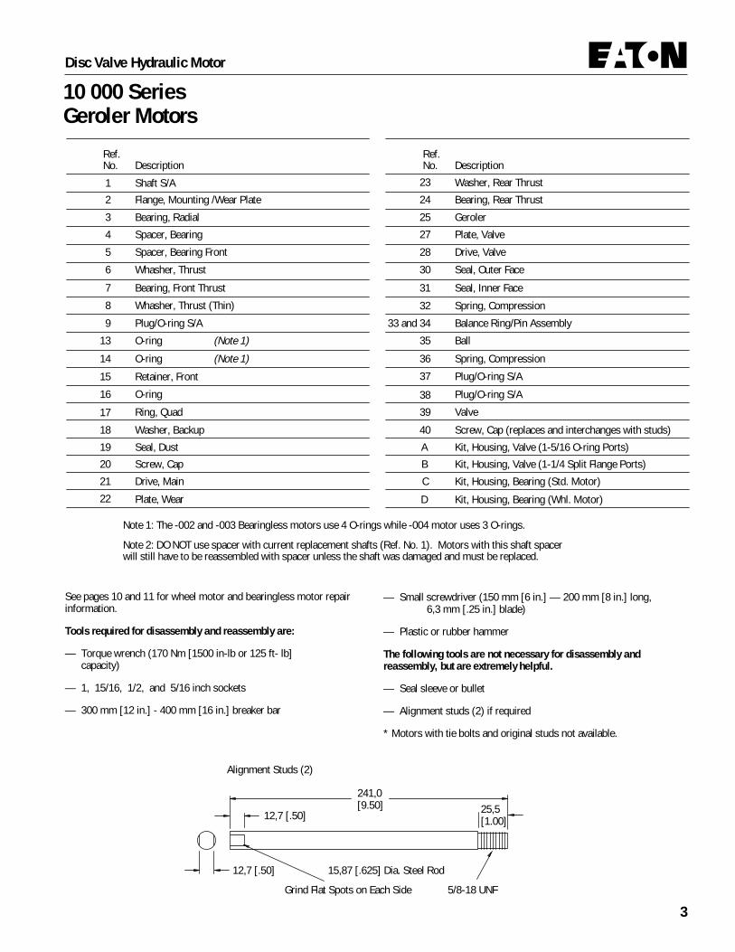
25,5[1.00]
241,0[9.50]
12,7 [.50] 15,87 [.625] Dia. Steel Rod
Grind Flat Spots on Each Side 5/8-18 UNF
Alignment Studs (2)
12,7 [.50]
See pages 10 and 11 for wheel motor and bearingless motor repairinformation.
Tools required for disassembly and reassembly are:
— Torque wrench (170 Nm [1500 in-lb or 125 ft- lb]capacity)
— 1, 15/16, 1/2, and 5/16 inch sockets
— 300 mm [12 in.] - 400 mm [16 in.] breaker bar
— Small screwdriver (150 mm [6 in.] — 200 mm [8 in.] long,6,3 mm [.25 in.] blade)
— Plastic or rubber hammer
The following tools are not necessary for disassembly andreassembly, but are extremely helpful.
— Seal sleeve or bullet
— Alignment studs (2) if required
* Motors with tie bolts and original studs not available.
Ref.No. Description
1 Shaft S/A
Plate, Wear22
Plug/O-ring S/A37
Washer, Rear Thrust23
Whasher, Thrust (Thin)8
Retainer, Front15
Screw, Cap20
Whasher, Thrust6
Bearing, Rear Thrust24
Bearing, Front Thrust7
Spacer, Bearing Front5
Balance Ring/Pin Assembly33 and 34
Ball35
Spring, Compression32
Spring, Compression36
27 Plate, Valve
25 Geroler
Drive, Main21
28 Drive, Valve
Plug/O-ring S/A38
Plug/O-ring S/A9
Ring, Quad17
Washer, Backup18
Seal, Inner Face31
Seal, Outer Face30
Ref.No. Description
4 Spacer, Bearing
Bearing, Radial3
Flange, Mounting /Wear Plate2
Seal, Dust19
O-ring16
O-ring14
O-ring
(Note 1)
(Note 1)13
39 Valve
Screw, Cap (replaces and interchanges with studs)40
Kit, Housing, Valve (1-5/16 O-ring Ports)A
Kit, Housing, Bearing (Std. Motor)C
Kit, Housing, Valve (1-1/4 Split Flange Ports)B
D Kit, Housing, Bearing (Whl. Motor)
Note 1: The -002 and -003 Bearingless motors use 4 O-rings while -004 motor uses 3 O-rings.
Note 2: DO NOT use spacer with current replacement shafts (Ref. No. 1). Motors with this shaft spacer will still have to be reassembled with spacer unless the shaft was damaged and must be replaced.

4
Disc Valve Hydraulic Motor
10 000 SeriesGeroler MotorsDisassembly
Cleanliness is extremely important when repairing a hydraulic motor.Work in a clean area. Before disconnecting the lines, clean the portarea of the motor thoroughly. Use a wire brush to remove foreignmaterial and debris from the exterior joints of the motor. Check theshaft and keyway, remove all nicks, burrs, or sharp edges that mightdamage the shaft seals when installing the retainer over the shaft.Before starting the disassembly procedures, drain the oil from insidethe motor.
1 Place the motor in a vise with the output shaft down, or place themotor (earlier models with studs) on a smooth, clean, flat surface; usea piece of wood under the center section of the motor to raise the valvehousing end of the motor off the surface of your work area, see Fig. 1,for these preparations.
Note: It may be helpful for reassembly to scribe a line across thelength of the motor.
Although not all drawings show the motor in a vise, we recommendthat you keep the motor in the vise during disassembly and reas-sembly. Follow the clamping procedures explained throughout themanual.
Line Scribedfor reassembly
MotorswithStuds
Figure 1
Figure 2
2 Remove 4 bolts (or nuts and washers for earlier models) frommotor. Remove studs (earlier models) per step 17.
3 Carefully lift the valve housing straight off. If this is done carefully,the springs and balance ring assembly will remain on the valve for easyremoval.
4 Remove 2 check valve plug assemblies (plugs, springs, and steelballs) from valve housing.
5 Place valve housing on bench with open end up, then carefullyremove 108 mm [4.25 in.] l.D. seal, and 9,4 mm[.37 in.] I.D. seal.
6 Remove 4 balance ring assembly springs.
7 Remove balance ring assembly.
8 Remove inner and outer seals from balance ring.
InnerSeal
Balance RingAss'y Spring (4)
ValveDrive
BalanceRing
OuterSeal Valve Valve Plate
Figure 3

5
Disc Valve Hydraulic Motor
10 000 SeriesGeroler MotorsDisassembly
9 Remove valve.
10 Remove valve plate.
11 Remove valve drive.
12 Remove Geroler. Retain rollers in Geroler assembly.
13 Remove 9,4 mm[.37 in.] I.D. seals, and 108 mm [4.25 in.] I.D.seals from the Geroler, 2 seals on each side of the Geroler.
14 Remove splined drive from bearing housing.
15 Remove wear plate.
16 Remove thrust bearing and thrust washer from wear plate.
17 Use a stud remover or vise grips to remove studs (earlier modelsonly) see Fig. 6.
18 Remove 9,4 mm[.37 in.] I.D. seal, and 108 mm [4.25 in.] I.D. sealfrom bearing housing.
19 Remove spacer from inside output shaft.
Note: Some units have shafts with a raised area at bottom of splinedcavity and do not use spacer.
20 Place bearing housing in vise, as shown in Figure 7. Loosen 8 capscrews (5/16 inch) in retainer.
Seals
Seals
Geroler
Figure 4
SplinedDrive
WearPlate
ThrustWasher
ThrustBearing
Figure 5
Spacer
Studs (4) (earlier models only)
Seals
Figure 6
SoftPad
Figure 7

6
Disc Valve Hydraulic Motor
10 000 SeriesGeroler MotorsDisassembly
DustSeal
CapScrew (8)
Retainer Seal
Back-upWasher
QuadSeal
Figure 8
PlugAssembly
Output Shaft
ThrustWashers
Thrust Bearing
Bearing Spacer
PlugAssembly
Figure 9
PlugAssembly
Output Shaft
Bearing Spacer
Figure 10
PlugAssembly
21 Place bearing housing on a clean, flat surface. Remove 8 capscrews and retainer.
22 Remove quad-ring seal, back-up washer, 0-ring seal, and dust sealfrom retainer. Use a small screw- driver to remove the dust seal. Donot damage bore of retainer.
23 Remove output shaft.
24 Remove 2 thrust washers and thrust bearing from the output shaft.
25 Remove bearing spacer.
26 Remove 2 plug assemblies (1 inch) from the bearing housing.
Note: The bearing housing and bearings inside the housing are notsold separately. These bearings are hydraulicly pressed into thebearing housing.
Reassembly
Check all mating surfaces. Replace any parts that have scratches orburrs that couId cause leakage. Clean all metal parts in clean solvent.Blow dry with air. Do not wipe with a cloth or paper towel because lintor other matter can get into the hydraulic system and cause damage.Do not use coarse grit or try to file these parts. Check around thekeyway and chamfered area of the shaft for burrs nicks or sharp edgesthat can damage the seals when reassembling the retainer.
Note: Lubricate all seals with petroleum jelly such as Vaseline. Referto the parts list (6-119) for replacement parts and proper seal kitnumber.

7
Disc Valve Hydraulic Motor
10 000 SeriesGeroler Motors
I Place bearing housing on a smooth, flat surface. Install 2 plugassemblies, see Figure 10. Tighten to 100 Nm[900 lb-in or 75 lb-ft].
2 Install bearing spacer in bearing housing.
3 Install output shaft. Rotate shaft while instaling in bearinghousing.
4 Install 2 thrust washers and thrust bearing. Install thrust bearingbetween the 2 thrust washers, thickest washer over shaft first, seeFigure 11.
5 Use a small press, if available, to install dust seal in retainer. Metalside of dust seal must face toward retainer, as shown in Figure 12. If apress is not available, use a plastic or rubber hammer to tap dust sealin place.
Thrust Bearing
ThrustWashers
ThickestWasher
Figure 11
Dust Seal
O-ring
Back-up Washer
Quad Seal
Retainer
Figure 12
Seal Replacement
6 Install back-up washer, quad ring seal, and 3-1/2” I.D. seal in theretainer. Apply petroleum jelly to inside diameter of dust seal and quadring seal.
7 Before installing retainer, place a protective sleeve or bullet, ifavailable, over shaft. To prevent damage to seals, install retainer overshaft with a twisting motion. Do not cut or distort retainer seals.Damage to these seals will cause external leakage.
8 Lubricate threads of 8 cap screws with a light film of oil. Installand finger tighten screws. Place unit in a vise, as shown in Figure 7.Tighten cap screws to 34 Nm [300 lb-in] of torque – in the sequenceshown in Figure 13.
9 Install key (when used) in key slot of shaft.
10 Reposition motor in vise, clamp housing flange, as shown in Fig. 1.
11 Pour a small amount of hydraulic oil inside outnut shaft.
Note: Spacers are not used on units that have a raised area at bottomof splined cavity.
12 Install spacer in output shaft, guide spacer with a pencil.
1
2
Figure 13
3
5 6
8
7 4
Torquing Sequence
Spacer
Stud (4) (earlier models only)
Seals
Figure 14
Resassembly

8
Disc Valve Hydraulic Motor
10 000 SeriesGeroler MotorsResassembly
13 Apply petroleum jelly to 108 mm [4.25 in. I.D. seal, and install inseal groove of the bearing housing see Fig. 14.
14 Apply petroleum jelly to 9,4 mm [.37 in. I.D. seal. Install seal incase drain groove of bearing housing.
15 Install 2 studs (earlier models), diagonally opposed, in bolt holesof bearing housing, see Fig. 15. If you replace studs with bolts, use 2studs for alignment purposes when stacking parts.
16 Install thrust washer and thrust bearing in wear plate – washer first,see Fig. 15. A light film of lubricant on the washer and bearing willhelp hold them in place.
17 Align case drain hole in wear plate with case drain hole in bearinghousing. Install wear plate flush against bearing housing, see Fig. 15.
Case Drain
WearPlate
ThrustWasher
ThrustBearing
Figure 15
Figure 16
Case Drain
Seals Seals Splined Drive
18 Install splined drive in output shaft. For 345 cm3/r [21.0 in3/r]displacement motor insert longer splined end of drive first, see Fig. 16.
19 Apply petroleum jelly on 2 seals 9,4 mm[.37 in.] I.D. and 2 seals108 mm [4.25 in.] I.D. Install them in the seal grooves of the Geroler,see Fig. 16, (one of each seal on both sides of the Geroler).
Note: Installation at this point involves 3 steps in the timing of themotor. Timing determines the direction of rotation of the output shaft.
The timing parts include . .
1. Geroler 3. Valve Plate2. Valve Drive 4. Valve
Timing Step 1—Locate the largest open pocket in the Geroler andmark it on the outside edge of the Geroler, See Fig. 17.
20 Align case drain hole in Geroler with case drain hole in wear-plate.Install Geroler on wear plate, see Fig. 16. Be sure to retain rollers inGeroler assembly.
21 Install valve drive in Geroler.
22 Align case drain hole in valve plate with case drain hole in Geroler.Install valve plate flush against Geroler, see Fig. 17.
Timing Step 2—Locate the slot opening in the valve plate which is inline with the largest open pocket of the Geroler. See Fig. 17
Anyone of 8 portsopen tooutsideof valve
Rotate ValveClockwise1 tooth toEngage Spline
ValveDrive
SlotOpening
AlignmentRef. Only
ReferenceMark
LargestOpen Pocket
CaseDrain
Timing Alignment
Figure 17
ValveDrive
CaseDrain Geroler

9
Disc Valve Hydraulic Motor
10 000 SeriesGeroler Motors
23 Use the following procedure for installing the valve on the valveplate.
Timing Step 3—Locate any one of the side openings of the valve thatgoes through to the face of the valve. Line up this side opening withthe open slot of the valve plate that is in line with the largest openpocket of the Geroler. Rotate the valve clockwise until the spline teethengage (1 spline tooth), see Fig. 17. This will provide the rotationshown when pressurized as shown, see Fig. 18.
24 Apply grease to 4 balance ring assembly springs. Install springs in4 holes located inside bore face of valve housing, see Fig. 19.
25 Apply a light film of petroleum jelly to 9,4 mm[.37 in.] I.D. seal.Install seal in case drain groove of valve housing.
26 Apply a light film of petroleum jelly to 108 mm [4.25 in.] I.D. seal.Install seal in outside seal groove of the valve housing.
Figure 18
ClockwiseRotation
Counter ClockwiseRotation
Balance RingAss'y Pin Hole (2)
Balance RingAss'y Spring (4)
ValveHousing
CaseDrain
Balance RingSpring Hole (4)
Figure 19
Figure 20Balance Ring
Inner SealPin Outer Seal
27 Apply petroleum jelly to inner and outer face seals. Install them onbalance ring as shown in Fig. 20.
Important: Install these face seals in the positions shown or themotor will not operate properly. Do not force or bend these faceseals. Any damage to these seals will affect the operation of themotor.
28 Align 2 pins in balance ring assembly with 2 holes in valve housingas shown in Fig. 19. Install the balance ring assembly in the valvehousing.
29 Insert a flat brass rod, or similar flat tool, through port of valvehousing to hold balance ring assembly in position until you install valvehousing. Align case drain hole in valve housing with case drain hole invalve plate. Install valve housing against valve plate, see Fig. 21.Remove brass rod as balance ring contacts the valve.
Note: After installing valve housing on valve plate, check for properplacement. Push down on the valve housing. You should get a slightspring action.
Note: After installing valve housing on valve plate, visually checkbetween body parts of motor for unseated seals.
Figure 21
Resassembly

10
Disc Valve Hydraulic Motor
10 000 SeriesGeroler MotorsResassembly
30 Install and finger tighten 2 bolts (or studs for earlier models)opposite alignment studs. Remove alignment studs and installremaining bolts (or studs, 4 washers, and 4 nuts for earlier models).Torque bolts (or nuts) to 130-150 Nm[95-110 lb-ft], in sequence, seeFig. 22.
31 Install 2 check balls in valve housing, one ball in each hole. To seatcheck balls, (on new valve housings only), tap lightly on ball with apunch, using a plastic (or rubber) hammer.
32 Install 2 springs in check valve holes, one spring in each hole.Install o-rings on plugs, then install plugs. Tighten to 9,6 Nm [85 lb-in].
33 Install case drain plug assembly. Tighten to 36 Nm [320 lb-in]. Onwheel motors, a different bearing housing is used, see Fig. 24. Otherthan this the parts are the same as the standard motor and the samedisassembly and reassembly procedures apply.
Bolt Torquing Sequence
Figure 22
14
32
Case Drain Plug Ass'y
Spring andSteel Ball (2)Plug (2)
Figure 23
O-ring (2)
Cap Screw
Dust Seal Bearing HousingBack-upWasher
QuadRingSeal
Retainer Seal
Figure 24
Wheel Motor
On wheel motors a different bearing housing is used, see Fig. 24.Other than this the parts are the same as the standard motor and thesame disassembly and reassembly procedures apply.
11
Disc Valve Hydraulic Motor
10 000 SeriesGeroler MotorsResassembly
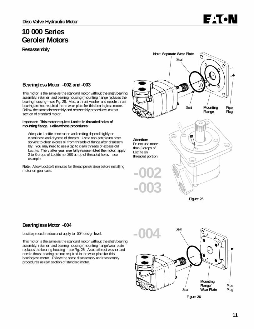
Seal MountingFlange
Attention:Do not use morethan 3 drops ofLoctite onthreaded portion.
PipePlug
SealNote: Separate Wear Plate
Figure 25
-002-003
Seal
Figure 26
Seal
MountingFlange/Wear Plate
PipePlug
-004
Bearingless Motor -002 and -003
This motor is the same as the standard motor without the shaft/bearingassembly, retainer, and bearing housing (mounting flange replaces thebearing housing—see Fig. 25. Also, a thrust washer and needle thrustbearing are not required in the wear plate for this bearingless motor.Follow the same disassembly and reassembly procedures as rearsection of standard motor.
Important: This motor requires Loctite in threaded holes ofmounting flange. Follow these procedures:
Adequate Loctite penetration and sealing depend highly oncleanliness and dryness of threads. Use a non-petroleum basesolvent to clean excess oil from threads of flange after disassembly. You may need to use a tap to clean threads of excess oldLoctite. Then, after you have fully reassembled the motor, apply2 to 3 drops of Loctite no. 290 at top of threaded holes—seeexample.
Note: Allow Loctite 5 minutes for thread penetration before installingmotor on gear case.
Bearingless Motor -004
Loctite procedure does not apply to -004 design level.
This motor is the same as the standard motor without the shaft/bearingassembly, retainer, and bearing housing (mounting flange/wear platereplaces the bearing housing—see Fig. 26. Also, a thrust washer andneedle thrust bearing are not required in the wear plate for thisbearingless motor. Follow the same disassembly and reassemblyprocedures as rear section of standard motor.

Disc Valve Hydraulic Motor
10 000 SeriesGeroler Motors
Product Numbers—10 000 Series MotorsDispl. cm3/r [in3/r] Product Number
Standard
Mounting
Bearingless
WheelMotor
2-1/4 in. Straight
Shaft
2-1/8 Inch16 T Splined
2-1/4 InchTapered
2-1/4 in. Straight
2-1/8 Inch16 T Splined
2-1/4 InchTapered
345[21.0]
119-1040
119-1044
121-1007
119-1032
119-1036
119-1048
120-1005
120-1017
120-1021
120-1009
120-1013
120-1025
121-1011
119-1028
480[29.3]
-1041
-1045
-1008
-1033
-1037
-1049
-1006
-1018
-1022
-1010
-1014
-1026
-1012
-1029
665[40.6]
-1042
-1046
-1009
-1034
-1038
-1050
-1007
-1019
-1023
-1011
-1015
-1027
-1013
-1030
940[57.4]
-1043
-1047
-1010
-1035
-1039
-1051
-1008
-1020
-1024
-1012
-1016
-1028
-1014
-1031
Ports
1-5/16 O-ring
1-1/4 Split Flange
1-1/4 Split Flange
1-5/16 O-ring
1-5/16 O-ring
1-1/4 Split Flange
1-1/4 Split Flange
1-1/4 Split Flange
1-5/16 O-ring
1-5/16 O-ring
1-5/16 O-ring
1-1/4 Split Flange
1-1/4 Split Flange
1-5/16 O-ring
Char-Lynn®
Product number
Eaton Corp. Hydraulics Div.Eden Prairie, MN 55344
Product Number000 0000 000
Product LineIdentificationNumber
ProductIdentificationNumber
EngineeringChangeCode
Week ofYear 01Thru 52
LastNumber(s)of Year
Date Code00 00
Each Order Must Include the Following:
How to Order Replacement Parts
1. Product Number2. Date Code3. Part Name
4. Part Number5. Quantity of Parts
For Additional Literature Contact Eaton Corp. HydraulicsDivision 15151 Highway 5 Eden Prairie, MN 55344.
Specifications and performance Data, Catalog No. 11-878
Replacement Part Numbers and Kit Information:10 000 Series Motors Parts Information No. 6-119.

© 2008 Eaton CorporationAll Rights ReservedPrinted in USADocument No. C-MOLO-TS011-ESupersedes 07-112November 2008
EatonFluid Power GroupHydraulics Business USA14615 Lone Oak RoadEden Prairie, MN 55344USATel: 952-937-9800Fax: 952-294-7722www.eaton.com/hydraulics
EatonFluid Power GroupHydraulics Business EuropeRoute de la Longeraie 71110 MorgesSwitzerlandTel: +41 (0) 21 811 4600Fax: +41 (0) 21 811 4601
EatonFluid Power GroupHydraulics Business Asia Pacific 11th Floor Hong Kong New World Tower 300 Huaihai Zhong Road Shanghai 200021 China Tel: 86-21-6387-9988 Fax: 86-21-6335-3912


![Repair Information - Eatonpub/@eaton/@hyd/documents/co… · Eaton May 1999 ® Medium Duty Piston Pump Repair Information Model 74624 and 74644, 82,6 cm3/r [5.04 in3/r] Displacement](https://img.dokumen.tips/doc/110x75/5b5784017f8b9ac31e8d9d73/repair-information-pubeatonhyddocumentsco-eaton-may-1999-medium-duty.jpg)

![Repair Information - Eatonpub/@eaton/@hyd/documents/content/...Repair Information. 2 Power Steering ... ( Circular ) Form Dia. 17,45 [.687] Pitch Dia..7500 [19,05] Fit Flat Root Side](https://img.dokumen.tips/doc/110x75/5aa301e77f8b9ada698da9d0/repair-information-pubeatonhyddocumentscontentrepair-information-2.jpg)


![Parts and Repair Information - Eatonpub/@eaton/@hyd/documents/co… · Eaton® Medium Duty Piston Pump Model 70122, 0 -19 cm3/r [0-1.16 in3/r] Displacement Pressure or Pressure-Flow](https://img.dokumen.tips/doc/110x75/5a9de5927f8b9adb388b97c2/parts-and-repair-information-pubeatonhyddocumentscoeaton-medium-duty.jpg)