Embed Size (px)
Citation preview
Signal Generator Fundamentals

Signal Generator Fundamentals
www.tektronix.com/signal_generators 3
The Complete Measurement System · · · · · · · · · · · · · · · 5
The Signal Generator · · · · · · · · · · · · · · · · · · · · · · · · · · · · 6
Analog or Digital? · · · · · · · · · · · · · · · · · · · · · · · · · · · · · · 7
Basic Signal Generator Applications· · · · · · · · · · · · · · · · 8
Verification · · · · · · · · · · · · · · · · · · · · · · · · · · · · · · · · · · · 8
Testing Digital Modulator Transmitters and Receivers · · 8
Characterization · · · · · · · · · · · · · · · · · · · · · · · · · · · · · · · 8
Testing D/A and A/D Converters · · · · · · · · · · · · · · · · · 8
Stress/Margin Testing · · · · · · · · · · · · · · · · · · · · · · · · · · · 9
Stressing Communication Receivers · · · · · · · · · · · · · · 9
Signal Generation Techniques · · · · · · · · · · · · · · · · · · · · 9
Understanding Waveforms· · · · · · · · · · · · · · · · · · · · · · · 10
Waveform Characteristics · · · · · · · · · · · · · · · · · · · · · · · 10
Amplitude, Frequency and Phase · · · · · · · · · · · · · · · 10
Rise and Fall Time · · · · · · · · · · · · · · · · · · · · · · · · · · · 10
Pulse Width · · · · · · · · · · · · · · · · · · · · · · · · · · · · · · · · 11
Offset · · · · · · · · · · · · · · · · · · · · · · · · · · · · · · · · · · · · · 12
Differential vs. Single-ended Signals · · · · · · · · · · · · · 12
Basic Waves · · · · · · · · · · · · · · · · · · · · · · · · · · · · · · · · · · 13
Sine Waves · · · · · · · · · · · · · · · · · · · · · · · · · · · · · · · · · 13
Square And Rectangular Waves · · · · · · · · · · · · · · · · 13
Sawtooth and Triangle Waves · · · · · · · · · · · · · · · · · · 14
Step and Pulse Shapes · · · · · · · · · · · · · · · · · · · · · · · 14
Complex Waves · · · · · · · · · · · · · · · · · · · · · · · · · · · · · · · · · 15
Signal Modulation · · · · · · · · · · · · · · · · · · · · · · · · · · · 15
Analog Modulation · · · · · · · · · · · · · · · · · · · · · · · · · 15
Digital Modulation · · · · · · · · · · · · · · · · · · · · · · · · · · 15
Frequency Sweep · · · · · · · · · · · · · · · · · · · · · · · · · · · 16
Quadrature Modulation · · · · · · · · · · · · · · · · · · · · · 16
Digital Patterns and Formats · · · · · · · · · · · · · · · · · · · 16
Bit Streams · · · · · · · · · · · · · · · · · · · · · · · · · · · · · · 17
Types of Signal Generators · · · · · · · · · · · · · · · · · · · · · · 17
Analog and Mixed Signal Generators · · · · · · · · · · · · · · 18
Types of Analog and Mixed Signal Generators · · · · · · 18
Arbitrary Generators · · · · · · · · · · · · · · · · · · · · · · · · · 18
Arbitrary/Function Generator (AFG) · · · · · · · · · · · · · · 18
Arbitrary Waveform Generator (AWG) · · · · · · · · · · · · 20
The Systems and Controls of a Mixed Signal Generator · · · 22
Performance Terms and Considerations · · · · · · · · · · · 24
Memory Depth (Record Length) · · · · · · · · · · · · · · · · 24
Sample (Clock) Rate · · · · · · · · · · · · · · · · · · · · · · · · · 24
Bandwidth · · · · · · · · · · · · · · · · · · · · · · · · · · · · · · · · · 26
Vertical (Amplitude) Resolution · · · · · · · · · · · · · · · · 26
Horizontal (Timing) Resolution · · · · · · · · · · · · · · · · · 27
Region Shift · · · · · · · · · · · · · · · · · · · · · · · · · · · · · · · · 27
Output Channels · · · · · · · · · · · · · · · · · · · · · · · · · · · · 28
Digital Outputs · · · · · · · · · · · · · · · · · · · · · · · · · · · · · · 28
Filtering · · · · · · · · · · · · · · · · · · · · · · · · · · · · · · · · · · · 29
Sequencing · · · · · · · · · · · · · · · · · · · · · · · · · · · · · · · · 29
Integrated Editors · · · · · · · · · · · · · · · · · · · · · · · · · · · 31
Data Import Functions · · · · · · · · · · · · · · · · · · · · · · · · 32
Table of Contents
4
Signal Generator Fundamentals
www.tektronix.com/signal_generators
Creating Waveforms Using Mixed Signal Generators · · 33
Creating Waveforms Using ArbExpress® · · · · · · · · · · · 34
Reating Waveforms Using SerialXpress™ · · · · · · · · · · · 35
Creating Waveforms Using RFXpress · · · · · · · · · · · · · 36
Pre/De-emphasized Signal Generation · · · · · · · · · · · 35
Multi-level Signal Generation · · · · · · · · · · · · · · · · · · · 35
Wideband RF Signal Generation · · · · · · · · · · · · · · · · 36
Wireless I/Q and IF Signal Generation · · · · · · · · · · · 36
Logic Signal Sources · · · · · · · · · · · · · · · · · · · · · · · · · · 37
Types of Logic Signal Sources · · · · · · · · · · · · · · · · · · · 37
Pulse Pattern Generator (PPG) · · · · · · · · · · · · · · · · · 37
Data Timing Generator (DTG) · · · · · · · · · · · · · · · · · · 37
The Systems and Controls of a Logic Signal Source · · 42
Performance Terms and Considerations · · · · · · · · · · · 43
Data Rate · · · · · · · · · · · · · · · · · · · · · · · · · · · · · · · · · 43
Pattern Depth · · · · · · · · · · · · · · · · · · · · · · · · · · · · · · 43
Vertical (Amplitude) Resolution · · · · · · · · · · · · · · · · · 43
Horizontal (Timing) Resolution · · · · · · · · · · · · · · · · · 43
Output Channels · · · · · · · · · · · · · · · · · · · · · · · · · · · · 44
Sequencing · · · · · · · · · · · · · · · · · · · · · · · · · · · · · · · · 44
Integrated Editors · · · · · · · · · · · · · · · · · · · · · · · · · · · 44
Data Import Functions · · · · · · · · · · · · · · · · · · · · · · · 44
Creating Waveforms Using a Logic Signal Source · · 45
Conclusion · · · · · · · · · · · · · · · · · · · · · · · 46
Glossary · · · · · · · · · · · · · · · · · · · · · · · · · 47
Signal Generator Fundamentals
www.tektronix.com/signal_generators 5
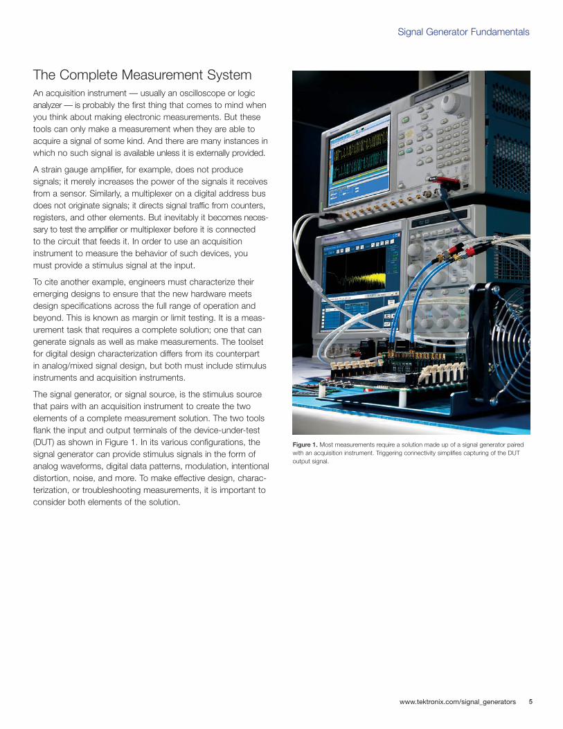
The Complete Measurement SystemAn acquisition instrument — usually an oscilloscope or logicanalyzer — is probably the first thing that comes to mind whenyou think about making electronic measurements. But thesetools can only make a measurement when they are able toacquire a signal of some kind. And there are many instances inwhich no such signal is available unless it is externally provided.
A strain gauge amplifier, for example, does not produce signals; it merely increases the power of the signals it receivesfrom a sensor. Similarly, a multiplexer on a digital address busdoes not originate signals; it directs signal traffic from counters,registers, and other elements. But inevitably it becomes neces-sary to test the amplifier or multiplexer before it is connected to the circuit that feeds it. In order to use an acquisition instrument to measure the behavior of such devices, you must provide a stimulus signal at the input.
To cite another example, engineers must characterize theiremerging designs to ensure that the new hardware meetsdesign specifications across the full range of operation andbeyond. This is known as margin or limit testing. It is a meas-urement task that requires a complete solution; one that cangenerate signals as well as make measurements. The toolsetfor digital design characterization differs from its counterpart in analog/mixed signal design, but both must include stimulusinstruments and acquisition instruments.
The signal generator, or signal source, is the stimulus sourcethat pairs with an acquisition instrument to create the two elements of a complete measurement solution. The two toolsflank the input and output terminals of the device-under-test(DUT) as shown in Figure 1. In its various configurations, thesignal generator can provide stimulus signals in the form ofanalog waveforms, digital data patterns, modulation, intentionaldistortion, noise, and more. To make effective design, charac-terization, or troubleshooting measurements, it is important toconsider both elements of the solution.
Figure 1. Most measurements require a solution made up of a signal generator pairedwith an acquisition instrument. Triggering connectivity simplifies capturing of the DUToutput signal.

6
Signal Generator Fundamentals
www.tektronix.com/signal_generators
The purpose of this document is to explain signal generators,their contribution to the measurement solution as a whole and their applications. Understanding the many types of signal generators and their capabilities is essential to yourwork as a researcher, engineer or technician. Selecting theright tool will make your job easier and will help you producefast, reliable results.
After reading this primer, you will be able to:
Describe how signal generators work
Describe electrical waveform types
Describe the differences between mixed signal generators and logic signal generators
Understand basic signal generator controls
Generate simple waveforms
Should you need additional assistance, or have any commentsor questions about the material in this primer, simply contactyour Tektronix representative, or visit www.tektronix.com/signal_generators.
The Signal GeneratorThe signal generator is exactly what its name implies: a gener-ator of signals used as a stimulus for electronic measurements.Most circuits require some type of input signal whose amplitudevaries over time. The signal may be a true bipolar AC1 signal(with peaks oscillating above and below a ground referencepoint) or it may vary over a range of DC offset voltages, eitherpositive or negative. It may be a sine wave or other analogfunction, a digital pulse, a binary pattern or a purely arbitrarywave shape.
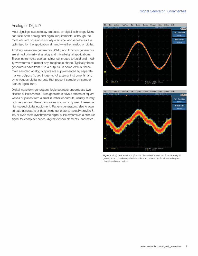
The signal generator can provide “ideal” waveforms or it mayadd known, repeatable amounts and types of distortion (or errors)to the signal it delivers. See Figure 2. This characteristic is oneof the signal generator’s greatest virtues, since it is often impossibleto create predictable distortion exactly when and where it’sneeded using only the circuit itself. The response of the DUT inthe presence of these distorted signals reveals its ability to han-dle stresses that fall outside the normal performance envelope.
1 Normally, the term “AC” denotes a signal that goes positive and negative about a 0 volt(ground) reference and therefore reverses the direction of current flow once in every cycle. Forthe purposes of this discussion, however, AC is defined as any varying signal, irrespective ofits relationship to ground. For example, a signal that oscillates between +1 V and +3 V, eventhough it always draws current in the same direction, is construed as an AC waveform. Mostsignal generators can produce either ground-centered (true AC) or offset waveforms.
Signal Generator Fundamentals
www.tektronix.com/signal_generators 7
Analog or Digital?
Most signal generators today are based on digital technology. Manycan fulfill both analog and digital requirements, although themost efficient solution is usually a source whose features areoptimized for the application at hand — either analog or digital.
Arbitrary waveform generators (AWG) and function generatorsare aimed primarily at analog and mixed-signal applications.These instruments use sampling techniques to build and mod-ify waveforms of almost any imaginable shape. Typically thesegenerators have from 1 to 4 outputs. In some AWGs, thesemain sampled analog outputs are supplemented by separatemarker outputs (to aid triggering of external instruments) andsynchronous digital outputs that present sample-by-sampledata in digital form.
Digital waveform generators (logic sources) encompass twoclasses of instruments. Pulse generators drive a stream of squarewaves or pulses from a small number of outputs, usually at veryhigh frequencies. These tools are most commonly used to exercisehigh-speed digital equipment. Pattern generators, also knownas data generators or data timing generators, typically provide 8,16, or even more synchronized digital pulse streams as a stimulussignal for computer buses, digital telecom elements, and more.
Figure 2. (Top) Ideal waveform; (Bottom) “Real-world” waveform. A versatile signal generator can provide controlled distortions and aberrations for stress testing and characterization of devices.
8
Signal Generator Fundamentals
www.tektronix.com/signal_generators
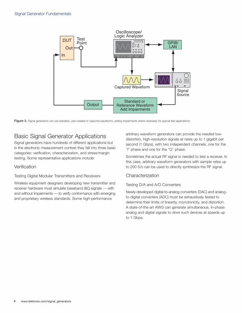
Signal generators have hundreds of different applications butin the electronic measurement context they fall into three basiccategories: verification, characterization, and stress/margintesting. Some representative applications include:
Verification
Testing Digital Modular Transmitters and Receivers
Wireless equipment designers developing new transmitter andreceiver hardware must simulate baseband I&Q signals — withand without impairments — to verify conformance with emergingand proprietary wireless standards. Some high-performance
arbitrary waveform generators can provide the needed low-distortion, high-resolution signals at rates up to 1 gigabit persecond (1 Gbps), with two independent channels, one for the“I” phase and one for the “Q” phase.
Sometimes the actual RF signal is needed to test a receiver. Inthis case, arbitrary waveform generators with sample rates upto 200 S/s can be used to directly synthesize the RF signal.
Characterization
Testing D/A and A/D Converters
Newly-developed digital-to-analog converters (DAC) and analog-to-digital converters (ADC) must be exhaustively tested todetermine their limits of linearity, monotonicity, and distortion.A state-of-the-art AWG can generate simultaneous, in-phaseanalog and digital signals to drive such devices at speeds upto 1 Gbps.
Figure 3. Signal generators can use standard, user-created or captured waveforms, adding impairments where necessary for special test applications.
DUT
Out
In
Test Point
Oscilloscope/Logic Analyzer
GPIB/LAN
SignalSource
Captured Waveform
Standard or Reference Waveform
Add ImpairmentsOutput
Basic Signal Generator Applications
Signal Generator Fundamentals
www.tektronix.com/signal_generators 9
Stress/Margin Testing
Stressing Communication Receivers
Engineers working with serial data stream architectures (commonly used in digital communications buses and diskdrive amplifiers) need to stress their devices with impairments,particularly jitter and timing violations. Advanced signal generatorssave the engineer untold hours of calculation by providing efficientbuilt-in jitter editing and generation tools. These instrumentscan shift critical signal edges as little as 200 fs (0.2 ps).
Signal Generation Techniques
There are several ways to create waveforms with a signal gen-erator. The choice of methods depends upon the informationavailable about the DUT and its input requirements; whetherthere is a need to add distortion or error signals, and othervariables. Modern high-performance signal generators offer at least three ways to develop waveforms:
Create: Brand new signals for circuit stimulus and testing
Replicate: Synthesize an unavailable real-world signal (captured from an oscilloscope or logic analyzer)
Generate: Ideal or stressed reference signals for industrystandards with specific tolerances
10
Signal Generator Fundamentals
www.tektronix.com/signal_generators
Waveform Characteristics
The term “wave” can be defined as a pattern of varying quan-titative values that repeats over some interval of time. Wavesare common in nature: sound waves, brain waves, oceanwaves, light waves, voltage waves, and many more. All areperiodically repeating phenomena. Signal generators are usuallyconcerned with producing electrical (typically voltage) wavesthat repeat in a controllable manner.
Each full repetition of a wave is known as a “cycle.” A waveformis a graphic representation of the wave’s activity — its variationover time. A voltage waveform is a classic Cartesian graphwith time on the horizontal axis and voltage on the verticalaxis. Note that some instruments can capture or produce current waveforms, power waveforms, or other alternatives. In this document we will concentrate on the conventional voltage vs. time waveform.
Amplitude, Frequency, and Phase
Waveforms have many characteristics but their key propertiespertain to amplitude, frequency, and phase:
Amplitude: A measure of the voltage “strength” of the waveform. Amplitude is constantly changing in an AC signal. Signal generators allow you to set a voltage range, for example, —3 to +3 volts. This will produce a signal that fluctuates between the two voltage values, with the rate of change dependent upon both the wave shape and the frequency.
Frequency: The rate at which full waveform cycles occur. Frequency is measured in Hertz (Hz), formerly known as cycles per second. Frequency is inversely related to the period (or wavelength) of the waveform, which is a measureof the distance between two similar peaks on adjacent waves. Higher frequencies have shorter periods.
Phase: In theory, the placement of a waveform cycle relative to a 0 degree point. In practice, phase is the time placement of a cycle relative to a reference waveform or point in time.
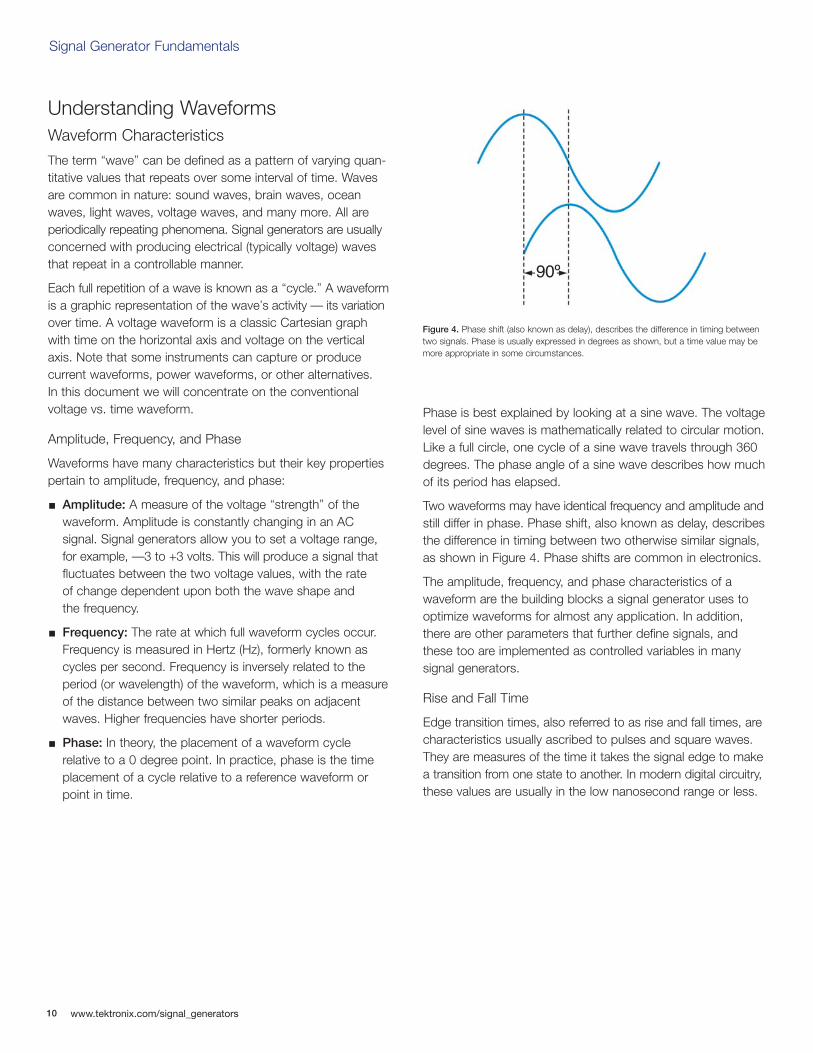
Phase is best explained by looking at a sine wave. The voltagelevel of sine waves is mathematically related to circular motion.Like a full circle, one cycle of a sine wave travels through 360degrees. The phase angle of a sine wave describes how muchof its period has elapsed.
Two waveforms may have identical frequency and amplitude andstill differ in phase. Phase shift, also known as delay, describesthe difference in timing between two otherwise similar signals,as shown in Figure 4. Phase shifts are common in electronics.
The amplitude, frequency, and phase characteristics of awaveform are the building blocks a signal generator uses to optimize waveforms for almost any application. In addition,there are other parameters that further define signals, andthese too are implemented as controlled variables in many signal generators.
Rise and Fall Time
Edge transition times, also referred to as rise and fall times, arecharacteristics usually ascribed to pulses and square waves.They are measures of the time it takes the signal edge to makea transition from one state to another. In modern digital circuitry,these values are usually in the low nanosecond range or less.
Understanding Waveforms
90º
Figure 4. Phase shift (also known as delay), describes the difference in timing betweentwo signals. Phase is usually expressed in degrees as shown, but a time value may bemore appropriate in some circumstances.
Signal Generator Fundamentals
www.tektronix.com/signal_generators 11
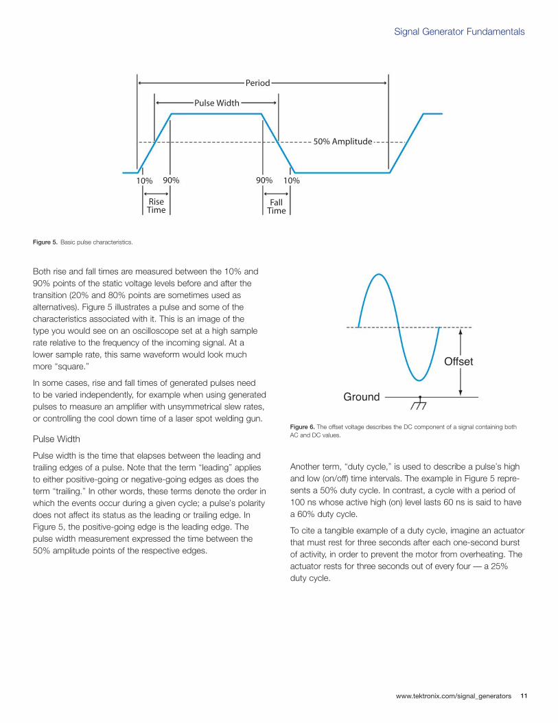
Both rise and fall times are measured between the 10% and90% points of the static voltage levels before and after thetransition (20% and 80% points are sometimes used as alternatives). Figure 5 illustrates a pulse and some of the characteristics associated with it. This is an image of the type you would see on an oscilloscope set at a high samplerate relative to the frequency of the incoming signal. At a lower sample rate, this same waveform would look muchmore “square.”
In some cases, rise and fall times of generated pulses need to be varied independently, for example when using generatedpulses to measure an amplifier with unsymmetrical slew rates,or controlling the cool down time of a laser spot welding gun.
Pulse Width
Pulse width is the time that elapses between the leading andtrailing edges of a pulse. Note that the term “leading” appliesto either positive-going or negative-going edges as does theterm “trailing.” In other words, these terms denote the order inwhich the events occur during a given cycle; a pulse’s polaritydoes not affect its status as the leading or trailing edge. InFigure 5, the positive-going edge is the leading edge. Thepulse width measurement expressed the time between the50% amplitude points of the respective edges.
Another term, “duty cycle,” is used to describe a pulse’s highand low (on/off) time intervals. The example in Figure 5 repre-sents a 50% duty cycle. In contrast, a cycle with a period of100 ns whose active high (on) level lasts 60 ns is said to havea 60% duty cycle.
To cite a tangible example of a duty cycle, imagine an actuatorthat must rest for three seconds after each one-second burstof activity, in order to prevent the motor from overheating. Theactuator rests for three seconds out of every four — a 25%duty cycle.
Figure 5. Basic pulse characteristics.
Period
Pulse Width
50% Amplitude
10%90% 90%10%
RiseTime
FallTime
Offset
Ground
Figure 6. The offset voltage describes the DC component of a signal containing bothAC and DC values.

12
Signal Generator Fundamentals
www.tektronix.com/signal_generators
Offset
Not all signals have their amplitude variations centered on a ground (0 V) reference. The “offset” voltage is the voltagebetween circuit ground and the center of the signal’s amplitude.In effect, the offset voltage expresses the DC component of asignal containing both AC and DC values, as shown in Figure 6.
Differential vs. Single-ended Signals
Differential signals are those that use two complementarypaths carrying copies of the same signal in equal and oppositepolarity (relative to ground). As the signal’s cycle proceeds andthe one path becomes more positive, the other becomes morenegative to the same degree. For example, if the signal’s valueat some instant in time was +1.5 volts on one of the paths,then the value on the other path would be exactly -1.5 volts(assuming the two signals were perfectly in phase). The differential architecture is good at rejecting crosstalk and noise and passing only the valid signal.
Single-ended operation is a more common architecture, inwhich there is only one path plus ground. Figure 7 illustratesboth single-ended and differential approaches.
Single-EndedDevice Output
DifferentialDevice Output
Figure 7. Single-ended and differential signals.
Signal Generator Fundamentals
www.tektronix.com/signal_generators 13
Basic Waves
Waveforms come in many shapes and forms. Most electronicmeasurements use one or more of the following wave shapes,often with noise or distortion added:
Sine waves
Square and rectangular waves
Sawtooth and triangle waves
Step and pulse shapes
Complex waves
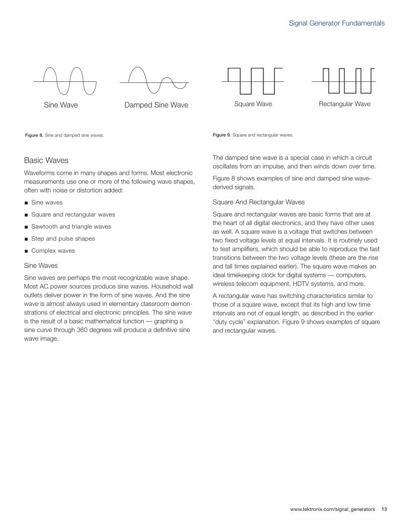
Sine Waves
Sine waves are perhaps the most recognizable wave shape.Most AC power sources produce sine waves. Household walloutlets deliver power in the form of sine waves. And the sinewave is almost always used in elementary classroom demon-strations of electrical and electronic principles. The sine waveis the result of a basic mathematical function — graphing a sine curve through 360 degrees will produce a definitive sinewave image.
The damped sine wave is a special case in which a circuitoscillates from an impulse, and then winds down over time.
Figure 8 shows examples of sine and damped sine wave-derived signals.
Square And Rectangular Waves
Square and rectangular waves are basic forms that are at the heart of all digital electronics, and they have other uses as well. A square wave is a voltage that switches between two fixed voltage levels at equal intervals. It is routinely used to test amplifiers, which should be able to reproduce the fasttransitions between the two voltage levels (these are the riseand fall times explained earlier). The square wave makes anideal timekeeping clock for digital systems — computers, wireless telecom equipment, HDTV systems, and more.
A rectangular wave has switching characteristics similar tothose of a square wave, except that its high and low timeintervals are not of equal length, as described in the earlier“duty cycle” explanation. Figure 9 shows examples of squareand rectangular waves.
Figure 8. Sine and damped sine waves.
Sine Wave Damped Sine Wave
Figure 9. Square and rectangular waves.
Square Wave Rectangular Wave
14
Signal Generator Fundamentals
www.tektronix.com/signal_generators
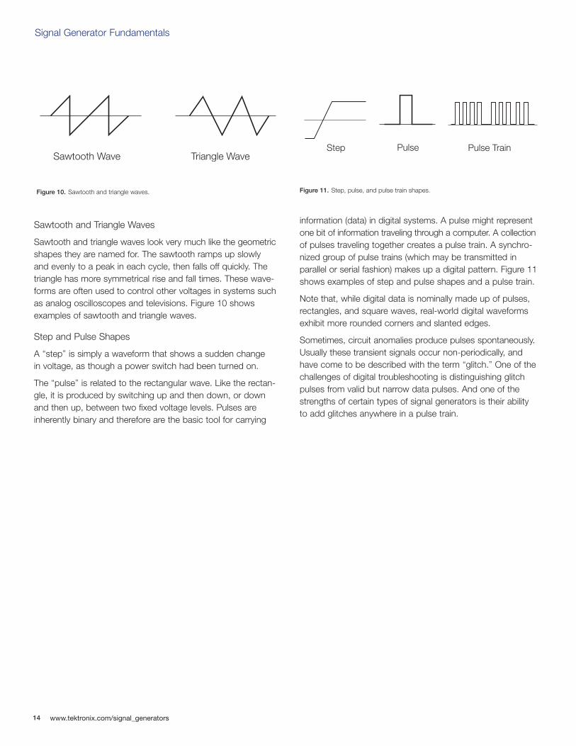
Sawtooth and Triangle Waves
Sawtooth and triangle waves look very much like the geometricshapes they are named for. The sawtooth ramps up slowlyand evenly to a peak in each cycle, then falls off quickly. Thetriangle has more symmetrical rise and fall times. These wave-forms are often used to control other voltages in systems suchas analog oscilloscopes and televisions. Figure 10 showsexamples of sawtooth and triangle waves.
Step and Pulse Shapes
A “step” is simply a waveform that shows a sudden change in voltage, as though a power switch had been turned on.
The “pulse” is related to the rectangular wave. Like the rectan-gle, it is produced by switching up and then down, or downand then up, between two fixed voltage levels. Pulses areinherently binary and therefore are the basic tool for carrying
information (data) in digital systems. A pulse might representone bit of information traveling through a computer. A collectionof pulses traveling together creates a pulse train. A synchro-nized group of pulse trains (which may be transmitted in parallel or serial fashion) makes up a digital pattern. Figure 11shows examples of step and pulse shapes and a pulse train.
Note that, while digital data is nominally made up of pulses,rectangles, and square waves, real-world digital waveformsexhibit more rounded corners and slanted edges.
Sometimes, circuit anomalies produce pulses spontaneously.Usually these transient signals occur non-periodically, andhave come to be described with the term “glitch.” One of thechallenges of digital troubleshooting is distinguishing glitchpulses from valid but narrow data pulses. And one of thestrengths of certain types of signal generators is their ability to add glitches anywhere in a pulse train.
Figure 11. Step, pulse, and pulse train shapes.
Step Pulse Pulse TrainSawtooth Wave Triangle Wave
Figure 10. Sawtooth and triangle waves.
Signal Generator Fundamentals
www.tektronix.com/signal_generators 15
Complex Waves
In operational electronic systems, waveforms rarely look likethe textbook examples explained above. Certain clock andcarrier signals are pure, but most other waveforms will exhibitsome unintended distortion (a by-product of circuit realities likedistributed capacitance, crosstalk, and more) or deliberatemodulation. Some waveforms may even include elements ofsines, squares, steps, and pulses.
Complex waves include:
Analog modulated, digitally modulated, pulse-width modulated, and quadrature modulated signals
Digital patterns and formats
Pseudo-random bit and word streams
Signal Modulation
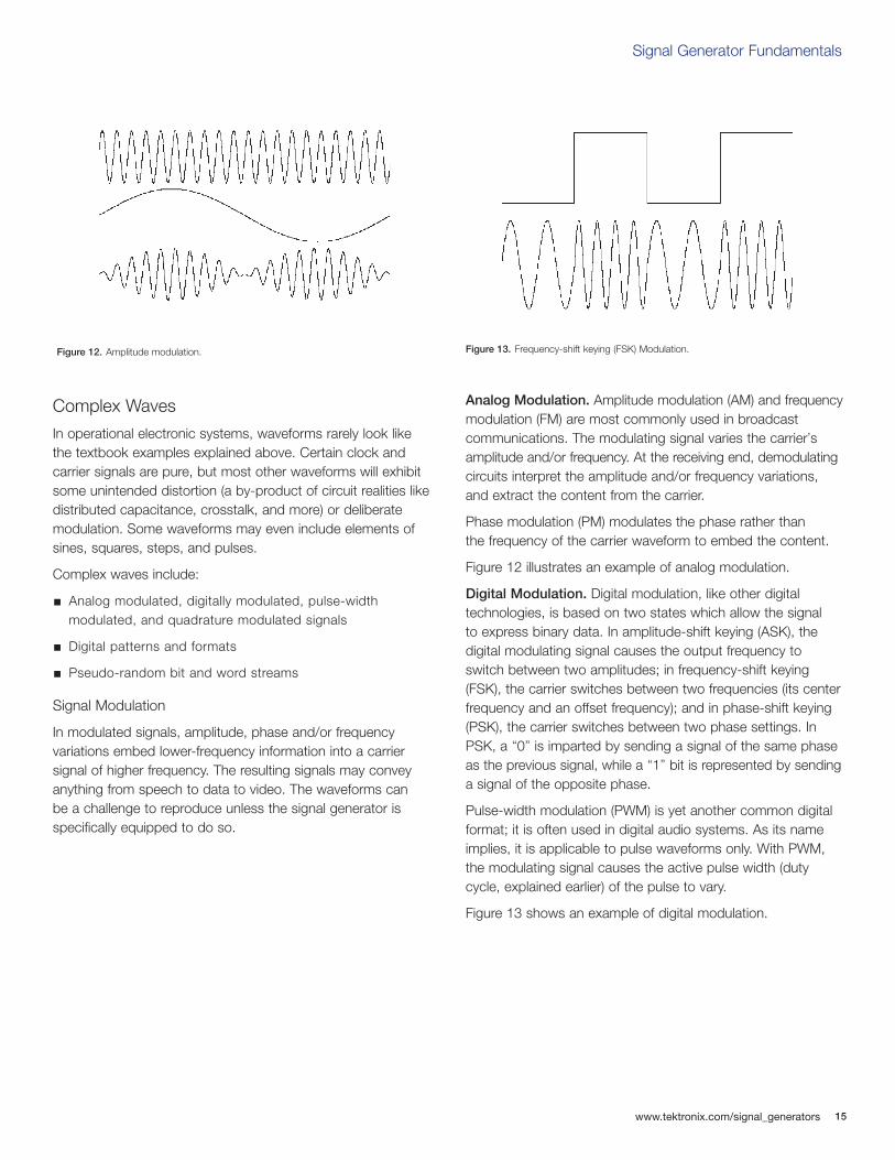
In modulated signals, amplitude, phase and/or frequency variations embed lower-frequency information into a carriersignal of higher frequency. The resulting signals may conveyanything from speech to data to video. The waveforms can be a challenge to reproduce unless the signal generator is specifically equipped to do so.
Analog Modulation. Amplitude modulation (AM) and frequencymodulation (FM) are most commonly used in broadcast communications. The modulating signal varies the carrier’samplitude and/or frequency. At the receiving end, demodulatingcircuits interpret the amplitude and/or frequency variations,and extract the content from the carrier.
Phase modulation (PM) modulates the phase rather than the frequency of the carrier waveform to embed the content.
Figure 12 illustrates an example of analog modulation.
Digital Modulation. Digital modulation, like other digital technologies, is based on two states which allow the signal to express binary data. In amplitude-shift keying (ASK), thedigital modulating signal causes the output frequency toswitch between two amplitudes; in frequency-shift keying(FSK), the carrier switches between two frequencies (its centerfrequency and an offset frequency); and in phase-shift keying(PSK), the carrier switches between two phase settings. InPSK, a “0” is imparted by sending a signal of the same phaseas the previous signal, while a “1” bit is represented by sendinga signal of the opposite phase.
Pulse-width modulation (PWM) is yet another common digitalformat; it is often used in digital audio systems. As its nameimplies, it is applicable to pulse waveforms only. With PWM,the modulating signal causes the active pulse width (dutycycle, explained earlier) of the pulse to vary.
Figure 13 shows an example of digital modulation.
Figure 12. Amplitude modulation. Figure 13. Frequency-shift keying (FSK) Modulation.

16
Signal Generator Fundamentals
www.tektronix.com/signal_generators
Frequency Sweep
Measuring the frequency characteristics of an electronicdevice calls for a “swept” sine wave — one that changes in frequency over a period of time. The frequency change occurslinearly in “Hz per seconds” or logarithmically in “Octaves per second.” Advanced sweep generators support sweepsequences with selectable start frequency, hold frequency,stop frequency and associated times. The signal generatoralso provides a trigger signal synchronously to the sweep tocontrol an oscilloscope that measures the output response of the device.
Quadrature Modulation. Today’s digital wireless communicationsnetworks are built on a foundation of quadrature (IQ) modulationtechnology. Two carriers — an in-phase (I) waveform and aquadrature-phase (Q) waveform that is delayed by exactly 90degrees relative to the “I” waveform — are modulated to producefour states of information. The two carriers are combined andtransmitted over one channel, then separated and demodulatedat the receiving end. The IQ format delivers far more informationthan other forms of analog and digital modulation: it increasesthe effective bandwidth of the system. Figure 15 depicts quadrature modulation.
Digital Patterns and Formats
A digital pattern consists of multiple synchronized pulsestreams that make up “words” of data that may be 8, 12, 16,or more bits wide. One class of signal generator, the digital patterngenerator, specializes in delivering words of data to digitalbuses and processors via parallel outputs. The words in thesepatterns are transmitted in a steady march of cycles, with theactivity for each bit in each cycle determined by the chosensignal format. The formats affect the width of the pulses withinthe cycles that compose the data streams.
The following list summarizes the most common signal formats. The first three format explanations assume that the cycle begins with a binary “0” value – that is, a low logicvoltage level.
Non-Return-to-Zero (NRZ): When a valid bit occurs in the cycle, the waveform switches to a “1” and stays at that value until the next cycle boundary.
Delayed Non-Return-to-Zero (DNRZ): Similar to NRZ, except that the waveform switches to a “1” after a specifieddelay time.
Return-to-Zero (RZ): When a valid bit is present, the waveform switches to a “1,” then back to a “0” within the same cycle.
Return-to-One (R1): In effect, the inverse of RZ. Unlike the other formats in this list, R1 assumes the cycle begins with a “1”, then switches to a “0” when the bit is valid, then switches back to a “1” before the cycle ends.
Figure 15. Quadrature modulation.
Figure 14. Frequency sweep of sine wave.
Signal Generator Fundamentals
www.tektronix.com/signal_generators 17
Bit Streams
Pseudo-random bit streams (PRBS) and pseudo-random word streams (PRWS) exist to make up for an innate limitationin digital computers: their inability to produce truly randomnumbers. Yet random events can have beneficial uses in digitalsystems. For example, perfectly “clean” digital video signalsmay have objectionable jagged lines and noticeable contourson surfaces that should be smooth. Adding a controlledamount of noise can hide these artifacts from the eye withoutcompromising the underlying information.
To create random noise, digital systems produce a stream ofnumbers that has the effect of randomness even though thenumbers follow a predictable mathematical pattern. These“pseudo-random” numbers are actually a set of sequencesrepeated at a random rate. The result is a PRBS. A pseudo-random word stream defines how multiple PRBS streams arepresented across the signal generator s parallel outputs.
PRWS is often used when testing serializers or multiplexers.These elements reassemble the PRWS signal into a serialstream of pseudo-random bits.
Types of Signal GeneratorsBroadly divided into mixed signal generators (arbitrary waveformgenerators and arbitrary/function generators) and logic sources(pulse or pattern generators), signal generators span the wholerange of signal-producing needs. Each of these types hasunique strengths that may make it more or less suitable forspecific applications.
Mixed signal generators are designed to output waveformswith analog characteristics. These may range from analogwaves such as sines and triangles to “square” waves thatexhibit the rounding and imperfections that are part of everyreal-world signal. In a versatile mixed signal generator, you cancontrol amplitude, frequency, and phase as well as DC offsetand rise and fall time; you can create aberrations such asovershoot; and you can add edge jitter, modulation and more.
True digital sources are meant to drive digital systems. Theiroutputs are binary pulse streams – a dedicated digital sourcecannot produce a sine or triangle wave. The features of a digital source are optimized for computer bus needs and similar applications. These features might include softwaretools to speed pattern development as well as hardware toolssuch as probes designed to match various logic families.
As explained earlier, almost all high-performance signal generatorstoday, from function generators to arbitrary sources to patterngenerators, are based on digital architectures, allowing flexibleprogrammability and exceptional accuracy.

18
Signal Generator Fundamentals
www.tektronix.com/signal_generators
Analog and Mixed Signal Generators
Types of Analog and Mixed Signal Generators
Arbitrary Generators
Historically, the task of producing diverse waveforms has beenfilled by separate, dedicated signal generators, from ultra-pureaudio sine wave generators to multi-GHz RF signal generators.While there are many commercial solutions, the user oftenmust custom-design or modify a signal generator for the projectat hand. It can be very difficult to design an instrumentation-quality signal generator, and of course, the time spent designingancillary test equipment is a costly distraction from the project itself.
Fortunately, digital sampling technology and signal processingtechniques have brought us a solution that answers almostany kind of signal generation need with just one type of instru-ment – the arbitrary generator. Arbitrary generators can beclassified into arbitrary/function generators (AFG) and arbitrarywaveform generators (AWG).
Arbitrary/Function Generator (AFG)
The arbitrary/function generator (AFG) serves a wide range of stimulus needs; in fact, it is the prevailing signal generatorarchitecture in the industry today. Typically, this instrumentoffers fewer waveform variations than its AWG equivalent, but with excellent stability and fast response to frequencychanges. If the DUT requires the classic sine and squarewaveforms (to name a few) and the ability to switch almostinstantly between two frequencies, the arbitrary/function generator (AFG) is the right tool. An additional virtue is theAFG’s low cost, which makes it very attractive for applicationsthat do not require an AWG’s versatility.
The AFG shares many features with the AWG, although theAFG is by design a more specialized instrument. The AFGoffers unique strengths: it produces stable waveforms in stan-dard shapes – particularly the all-important sine and squarewaves – that are both accurate and agile. Agility is the abilityto change quickly and cleanly from one frequency to another.
Most AFGs offer some subset of the following familiar wave shapes:
Sine
Square
Triangle
Sweep
Pulse
Ramp
Modulation
Haversine
While AWGs can certainly provide these same waveforms,today’s AFGs are designed to provide improved phase, frequency, and amplitude control of the output signal.Moreover, many AFGs offer a way to modulate the signal from internal or external sources, which is essential for sometypes of standards compliance testing.
In the past, AFGs created their output signals using analogoscillators and signal conditioning. More recent AFGs rely onDirect Digital Synthesis (DDS) techniques to determine the rateat which samples are clocked out of their memory.
Signal Generator Fundamentals
www.tektronix.com/signal_generators 19
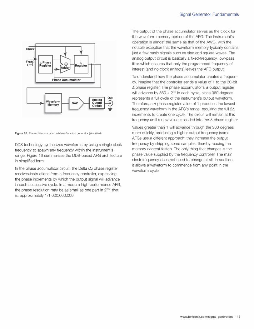
DDS technology synthesizes waveforms by using a single clockfrequency to spawn any frequency within the instrument’srange. Figure 16 summarizes the DDS-based AFG architecturein simplified form.
In the phase accumulator circuit, the Delta (∆) phase registerreceives instructions from a frequency controller, expressingthe phase increments by which the output signal will advancein each successive cycle. In a modern high-performance AFG,the phase resolution may be as small as one part in 230, thatis, approximately 1/1,000,000,000.
The output of the phase accumulator serves as the clock forthe waveform memory portion of the AFG. The instrument’soperation is almost the same as that of the AWG, with thenotable exception that the waveform memory typically containsjust a few basic signals such as sine and square waves. Theanalog output circuit is basically a fixed-frequency, low-passfilter which ensures that only the programmed frequency ofinterest (and no clock artifacts) leaves the AFG output.
To understand how the phase accumulator creates a frequen-cy, imagine that the controller sends a value of 1 to the 30-bit∆ phase register. The phase accumulator’s ∆ output registerwill advance by 360 ÷ 230 in each cycle, since 360 degreesrepresents a full cycle of the instrument’s output waveform.Therefore, a ∆ phase register value of 1 produces the lowestfrequency waveform in the AFG’s range, requiring the full 2∆increments to create one cycle. The circuit will remain at thisfrequency until a new value is loaded into the ∆ phase register.
Values greater than 1 will advance through the 360 degreesmore quickly, producing a higher output frequency (someAFGs use a different approach: they increase the output frequency by skipping some samples, thereby reading thememory content faster). The only thing that changes is thephase value supplied by the frequency controller. The mainclock frequency does not need to change at all. In addition, it allows a waveform to commence from any point in thewaveform cycle.
Clock
Freq.Ctrl.
AdderRegister
Phase Accumulator
PhaseRegister
WaveformMemory DAC
AnalogOutputCircuit
Out
Figure 16. The architecture of an arbitrary/function generator (simplified).
20
Signal Generator Fundamentals
www.tektronix.com/signal_generators
For example, assume it is necessary to produce a sine wavethat begins at the peak of the positive-going part of the cycle.Basic math tells us that this peak occurs at 90 degrees.Therefore:
230 increments = 360¡ ; and
90¡ = 360¡ ÷ 4; then,
90¡ = 230 ÷ 4
When the phase accumulator receives a value equivalent to(230 ÷ 4), it will prompt the waveform memory to start from alocation containing the positive peak voltage of the sine wave.
The typical AFG has several standard waveforms stored in a preprogrammed part of its memory. In general, sine andsquare waves are the most widely used for many test applica-tions. Arbitrary waveforms are held in a user programmablepart of the memory. Waveshapes can be defined with thesame flexibility as in conventional AWGs. However, the DDSarchitecture does not support memory segmentation andwaveform sequencing. These advanced capabilities arereserved for high performance AWGs.
DDS architecture provides exceptional frequency agility, makingit easy to program both frequency and phase changes on thefly, which is useful to test any type of FM DUT – radio andsatellite system components, for example. And if the specificAFG’s frequency range is sufficient, it’s an ideal signal genera-tor for test on FSK and frequency-hopping telephony tech-nologies such as GSM.
Although it cannot equal the AWG’s ability to create virtually anyimaginable waveform, the AFG produces the most commontest signals used in labs, repair facilities and design departmentsaround the world. Moreover, it delivers excellent frequencyagility. And importantly, the AFG is often a very cost-effectiveway to get the job done.
Arbitrary Waveform Generator (AWG)
Whether you want a data stream shaped by a precise Lorentzianpulse for disk drive characterization, or a complex modulatedRF signal to test a GSM- or CDMA-based telephone handset,the arbitrary waveform generator (AWG) can produce anywaveform you can imagine. You can use a variety of methods –from mathematical formulae to “drawing” the waveform – tocreate the needed output.
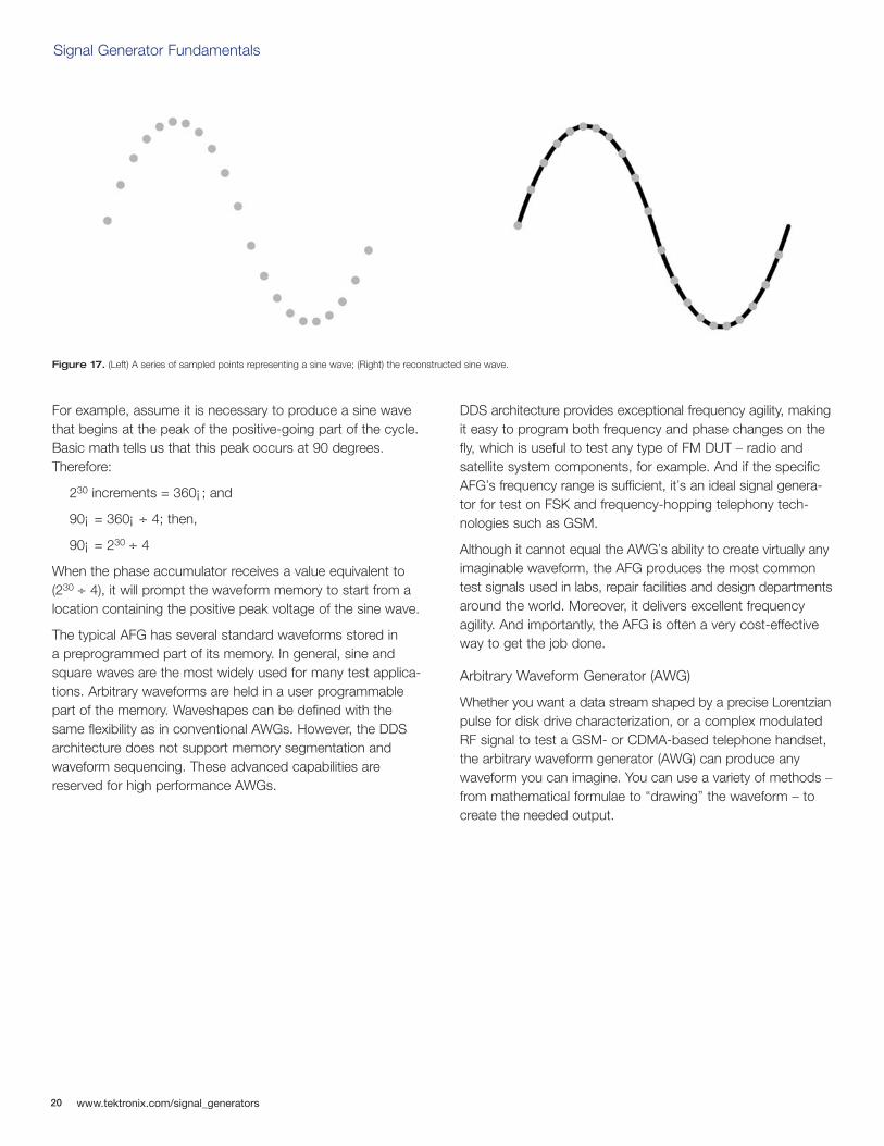
Figure 17. (Left) A series of sampled points representing a sine wave; (Right) the reconstructed sine wave.
Signal Generator Fundamentals
www.tektronix.com/signal_generators 21
Fundamentally, an arbitrary waveform generator (AWG) is asophisticated playback system that delivers waveforms basedon stored digital data that describes the constantly changingvoltage levels of an AC signal. It is a tool whose block diagramis deceptively simple. To put the AWG concept in familiar terms,it is much like a CD player that reads out stored data (in theAWG, its own waveform memory; in the CD player, the discitself) in real time. Both put out an analog signal, or waveform.
To understand the AWG, it’s first necessary to grasp the broadconcepts of digital sampling. Digital sampling is exactly whatits name implies: defining a signal using samples, or datapoints, that represent a series of voltage measurements alongthe slope of the waveform. These samples may be determinedby actually measuring a waveform with an instrument such asan oscilloscope, or by using graphical or mathematical tech-niques. Figure 17 (Left) depicts a series of sampled points. All of the points are sampled at uniform time intervals, eventhough the curve makes their spacing appear to vary. In anAWG, the sampled values are stored in binary form in a fastRandom Access Memory (RAM).
With the stored information, the signal can be reconstructed(bottom) at any time by reading back the memory locationsand feeding the data points through a digital-to-analog con-verter (DAC). Figure 17 (Right) depicts the result. Note that theAWG s output circuitry filters between the points to connect thedots and create a clean, uninterrupted waveform shape. TheDUT does not “see” these dots as discrete points, but as acontinuous analog waveform.
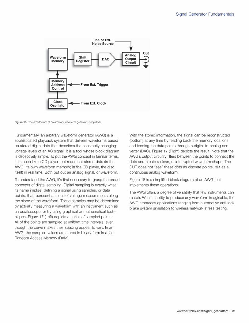
Figure 18 is a simplified block diagram of an AWG that implements these operations.
The AWG offers a degree of versatility that few instruments canmatch. With its ability to produce any waveform imaginable, theAWG embraces applications ranging from automotive anti-lockbrake system simulation to wireless network stress testing.
Figure 18. The architecture of an arbitrary waveform generator (simplified).
WaveformMemory
ShiftRegister DAC
AnalogOutputCircuit
Out
Int. or Ext.Noise Source
MemoryAddressControl
ClockOscillator
From Ext. Trigger
From Ext. Clock
22
Signal Generator Fundamentals
www.tektronix.com/signal_generators
The Systems and Controls of a Mixed Signal Generator
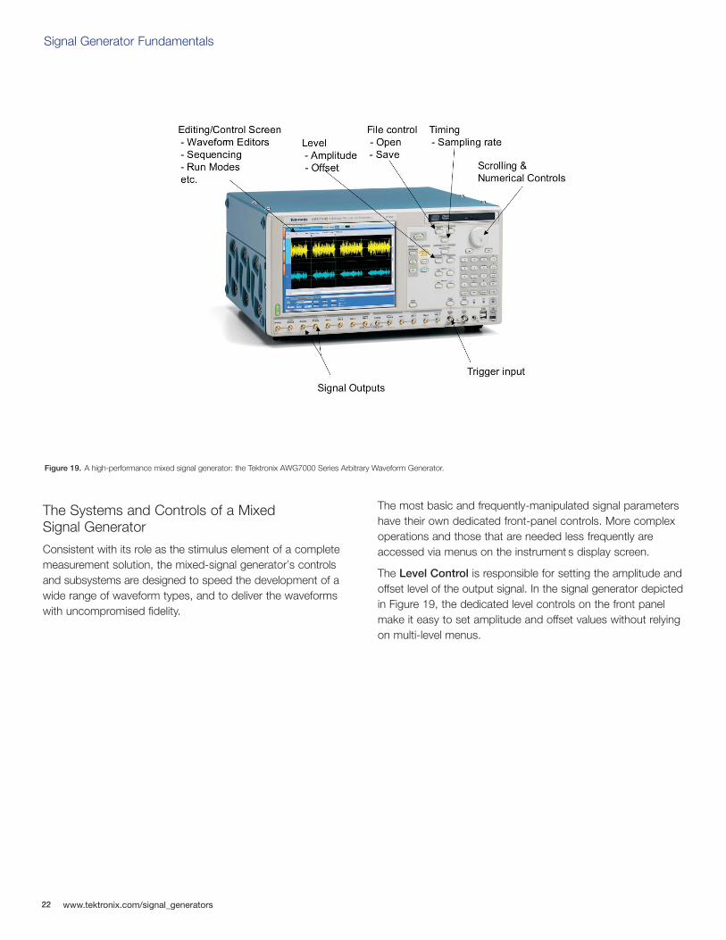
Consistent with its role as the stimulus element of a completemeasurement solution, the mixed-signal generator’s controlsand subsystems are designed to speed the development of awide range of waveform types, and to deliver the waveformswith uncompromised fidelity.
The most basic and frequently-manipulated signal parametershave their own dedicated front-panel controls. More complexoperations and those that are needed less frequently areaccessed via menus on the instrument s display screen.
The Level Control is responsible for setting the amplitude andoffset level of the output signal. In the signal generator depictedin Figure 19, the dedicated level controls on the front panelmake it easy to set amplitude and offset values without relyingon multi-level menus.
Figure 19. A high-performance mixed signal generator: the Tektronix AWG7000 Series Arbitrary Waveform Generator.
Signal Generator Fundamentals
www.tektronix.com/signal_generators 23
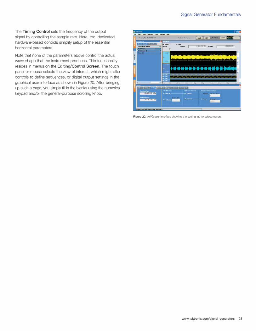
The Timing Control sets the frequency of the output signal by controlling the sample rate. Here, too, dedicatedhardware-based controls simplify setup of the essential horizontal parameters.
Note that none of the parameters above control the actualwave shape that the instrument produces. This functionalityresides in menus on the Editing/Control Screen. The touchpanel or mouse selects the view of interest, which might offercontrols to define sequences, or digital output settings in thegraphical user interface as shown in Figure 20. After bringingup such a page, you simply fill in the blanks using the numericalkeypad and/or the general-purpose scrolling knob.
Figure 20. AWG user interface showing the setting tab to select menus.
24
Signal Generator Fundamentals
www.tektronix.com/signal_generators
Performance Terms and Considerations
Following are some definitions of parameters that describe the performance of a mixed signal generator. You will see theseterms used in brochures, reference books, tutorials almostanywhere signal generators or their applications are described.
Memory Depth (Record Length)
Memory depth, or record length, goes hand-in-hand with clockfrequency. Memory depth determines the maximum number of samples that can be stored. Every waveform sample pointoccupies a memory location. Each location equates to a sam-ple interval’s worth of time at the current clock frequency. If theclock is running at 100 MHz, for example, the stored samplesare separated by 10 ns.
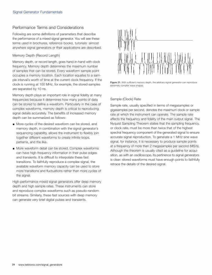
Memory depth plays an important role in signal fidelity at manyfrequencies because it determines how many points of datacan be stored to define a waveform. Particularly in the case ofcomplex waveforms, memory depth is critical to reproducingsignal details accurately. The benefits of increased memorydepth can be summarized as follows:
More cycles of the desired waveform can be stored, and memory depth, in combination with the signal generator’s sequencing capability, allows the instrument to flexibly join together different waveforms to create infinite loops, patterns, and the like.
More waveform detail can be stored. Complex waveforms can have high-frequency information in their pulse edges and transients. It is difficult to interpolate these fast transitions. To faithfully reproduce a complex signal, the available waveform memory capacity can be used to store more transitions and fluctuations rather than more cycles of the signal.
High-performance mixed signal generators offer deep memorydepth and high sample rates. These instruments can storeand reproduce complex waveforms such as pseudo-randombit streams. Similarly, these fast sources with deep memorycan generate very brief digital pulses and transients.
Sample (Clock) Rate
Sample rate, usually specified in terms of megasamples orgigasamples per second, denotes the maximum clock or samplerate at which the instrument can operate. The sample rateaffects the frequency and fidelity of the main output signal. TheNyquist Sampling Theorem states that the sampling frequency,or clock rate, must be more than twice that of the highestspectral frequency component of the generated signal to ensureaccurate signal reproduction. To generate a 1 MHz sine wavesignal, for instance, it is necessary to produce sample pointsat a frequency of more than 2 megasamples per second (MS/s).Although the theorem is usually cited as a guideline for acqui-sition, as with an oscilloscope, its pertinence to signal generatorsis clear: stored waveforms must have enough points to faithfullyretrace the details of the desired signal.
Figure 21. With sufficient memory depth, the arbitrary signal generator can reproduceextremely complex wave shapes.
Signal Generator Fundamentals
www.tektronix.com/signal_generators 25
The signal generator can take these points and read them out ofmemory at any frequency within its specified limits. If a set ofstored points conforms to the Nyquist Theorem and describesa sine wave, then the signal generator will filter the waveformappropriately and output a sine wave.
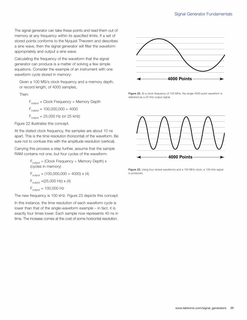
Calculating the frequency of the waveform that the signal generator can produce is a matter of solving a few simpleequations. Consider the example of an instrument with onewaveform cycle stored in memory:
Given a 100 MS/s clock frequency and a memory depth, or record length, of 4000 samples,
Then:
Foutput = Clock Frequency ÷ Memory Depth
Foutput = 100,000,000 ÷ 4000
Foutput = 25,000 Hz (or 25 kHz)
Figure 22 illustrates this concept.
At the stated clock frequency, the samples are about 10 nsapart. This is the time resolution (horizontal) of the waveform. Besure not to confuse this with the amplitude resolution (vertical).
Carrying this process a step further, assume that the sampleRAM contains not one, but four cycles of the waveform:
Foutput = (Clock Frequency ÷ Memory Depth) x(cycles in memory)
Foutput = (100,000,000 ÷ 4000) x (4)
Foutput =(25,000 Hz) x (4)
Foutput = 100,000 Hz
The new frequency is 100 kHz. Figure 23 depicts this concept.
In this instance, the time resolution of each waveform cycle islower than that of the single-waveform example – in fact, it isexactly four times lower. Each sample now represents 40 ns intime. The increase comes at the cost of some horizontal resolution.
Figure 22. At a clock frequency of 100 MHz, the single 4000-point waveform is delivered as a 25 kHz output signal.
Figure 23. Using four stored waveforms and a 100 MHz clock, a 100 kHz signal is produced.
26
Signal Generator Fundamentals
www.tektronix.com/signal_generators
Bandwidth
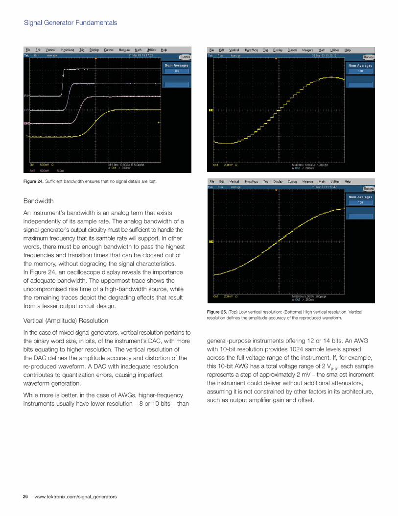
An instrument’s bandwidth is an analog term that exists independently of its sample rate. The analog bandwidth of asignal generator’s output circuitry must be sufficient to handle themaximum frequency that its sample rate will support. In otherwords, there must be enough bandwidth to pass the highestfrequencies and transition times that can be clocked out of the memory, without degrading the signal characteristics. In Figure 24, an oscilloscope display reveals the importance of adequate bandwidth. The uppermost trace shows theuncompromised rise time of a high-bandwidth source, whilethe remaining traces depict the degrading effects that resultfrom a lesser output circuit design.
Vertical (Amplitude) Resolution
In the case of mixed signal generators, vertical resolution pertains tothe binary word size, in bits, of the instrument’s DAC, with morebits equating to higher resolution. The vertical resolution of the DAC defines the amplitude accuracy and distortion of there-produced waveform. A DAC with inadequate resolutioncontributes to quantization errors, causing imperfect waveform generation.
While more is better, in the case of AWGs, higher-frequencyinstruments usually have lower resolution – 8 or 10 bits – than
general-purpose instruments offering 12 or 14 bits. An AWGwith 10-bit resolution provides 1024 sample levels spreadacross the full voltage range of the instrument. If, for example,this 10-bit AWG has a total voltage range of 2 Vp-p, each samplerepresents a step of approximately 2 mV – the smallest incrementthe instrument could deliver without additional attenuators,assuming it is not constrained by other factors in its architecture,such as output amplifier gain and offset.
Figure 24. Sufficient bandwidth ensures that no signal details are lost.
Figure 25. (Top) Low vertical resolution; (Bottome) High vertical resolution. Vertical resolution defines the amplitude accuracy of the reproduced waveform.
Signal Generator Fundamentals
www.tektronix.com/signal_generators 27
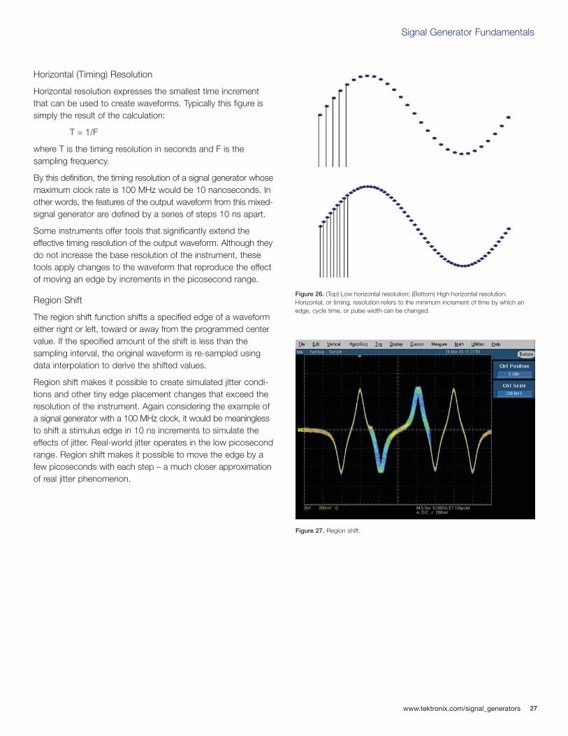
Horizontal (Timing) Resolution
Horizontal resolution expresses the smallest time incrementthat can be used to create waveforms. Typically this figure issimply the result of the calculation:
T = 1/F
where T is the timing resolution in seconds and F is the sampling frequency.
By this definition, the timing resolution of a signal generator whosemaximum clock rate is 100 MHz would be 10 nanoseconds. Inother words, the features of the output waveform from this mixed-signal generator are defined by a series of steps 10 ns apart.
Some instruments offer tools that significantly extend theeffective timing resolution of the output waveform. Although theydo not increase the base resolution of the instrument, thesetools apply changes to the waveform that reproduce the effectof moving an edge by increments in the picosecond range.
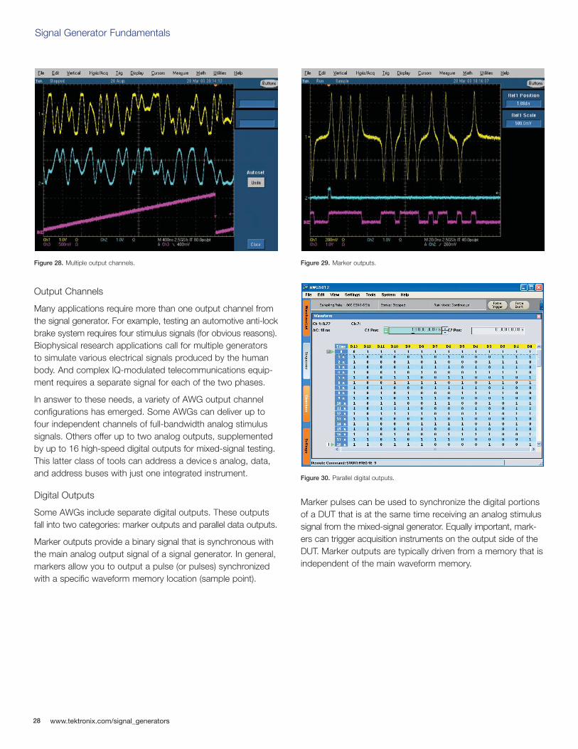
Region Shift
The region shift function shifts a specified edge of a waveformeither right or left, toward or away from the programmed centervalue. If the specified amount of the shift is less than the sampling interval, the original waveform is re-sampled usingdata interpolation to derive the shifted values.
Region shift makes it possible to create simulated jitter condi-tions and other tiny edge placement changes that exceed theresolution of the instrument. Again considering the example ofa signal generator with a 100 MHz clock, it would be meaninglessto shift a stimulus edge in 10 ns increments to simulate theeffects of jitter. Real-world jitter operates in the low picosecondrange. Region shift makes it possible to move the edge by afew picoseconds with each step – a much closer approximationof real jitter phenomenon.
Figure 27. Region shift.
Figure 26. (Top) Low horizontal resolution; (Bottom) High horizontal resolution.Horizontal, or timing, resolution refers to the minimum increment of time by which anedge, cycle time, or pulse width can be changed.
28
Signal Generator Fundamentals
www.tektronix.com/signal_generators
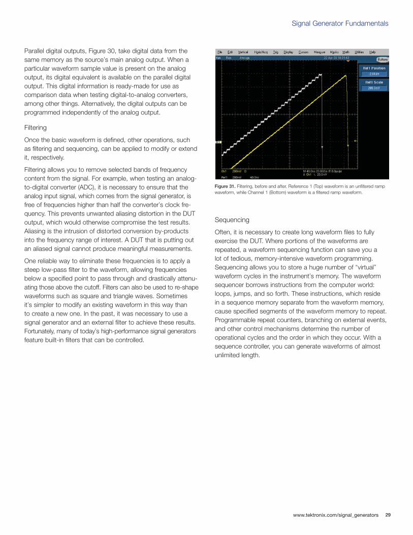
Output Channels
Many applications require more than one output channel fromthe signal generator. For example, testing an automotive anti-lockbrake system requires four stimulus signals (for obvious reasons).Biophysical research applications call for multiple generators to simulate various electrical signals produced by the humanbody. And complex IQ-modulated telecommunications equip-ment requires a separate signal for each of the two phases.
In answer to these needs, a variety of AWG output channelconfigurations has emerged. Some AWGs can deliver up tofour independent channels of full-bandwidth analog stimulussignals. Others offer up to two analog outputs, supplementedby up to 16 high-speed digital outputs for mixed-signal testing.This latter class of tools can address a device s analog, data,and address buses with just one integrated instrument.
Digital Outputs
Some AWGs include separate digital outputs. These outputsfall into two categories: marker outputs and parallel data outputs.
Marker outputs provide a binary signal that is synchronous withthe main analog output signal of a signal generator. In general,markers allow you to output a pulse (or pulses) synchronizedwith a specific waveform memory location (sample point).
Marker pulses can be used to synchronize the digital portionsof a DUT that is at the same time receiving an analog stimulussignal from the mixed-signal generator. Equally important, mark-ers can trigger acquisition instruments on the output side of theDUT. Marker outputs are typically driven from a memory that isindependent of the main waveform memory.
Figure 28. Multiple output channels. Figure 29. Marker outputs.
Figure 30. Parallel digital outputs.
Signal Generator Fundamentals
www.tektronix.com/signal_generators 29
Parallel digital outputs, Figure 30, take digital data from thesame memory as the source’s main analog output. When aparticular waveform sample value is present on the analogoutput, its digital equivalent is available on the parallel digitaloutput. This digital information is ready-made for use as comparison data when testing digital-to-analog converters,among other things. Alternatively, the digital outputs can beprogrammed independently of the analog output.
Filtering
Once the basic waveform is defined, other operations, such as filtering and sequencing, can be applied to modify or extendit, respectively.
Filtering allows you to remove selected bands of frequencycontent from the signal. For example, when testing an analog-to-digital converter (ADC), it is necessary to ensure that theanalog input signal, which comes from the signal generator, isfree of frequencies higher than half the converter’s clock fre-quency. This prevents unwanted aliasing distortion in the DUToutput, which would otherwise compromise the test results.Aliasing is the intrusion of distorted conversion by-productsinto the frequency range of interest. A DUT that is putting outan aliased signal cannot produce meaningful measurements.
One reliable way to eliminate these frequencies is to apply asteep low-pass filter to the waveform, allowing frequenciesbelow a specified point to pass through and drastically attenu-ating those above the cutoff. Filters can also be used to re-shapewaveforms such as square and triangle waves. Sometimes it’s simpler to modify an existing waveform in this way than to create a new one. In the past, it was necessary to use asignal generator and an external filter to achieve these results.Fortunately, many of today’s high-performance signal generatorsfeature built-in filters that can be controlled.
Sequencing
Often, it is necessary to create long waveform files to fullyexercise the DUT. Where portions of the waveforms arerepeated, a waveform sequencing function can save you a lot of tedious, memory-intensive waveform programming.Sequencing allows you to store a huge number of “virtual”waveform cycles in the instrument’s memory. The waveformsequencer borrows instructions from the computer world:loops, jumps, and so forth. These instructions, which reside in a sequence memory separate from the waveform memory,cause specified segments of the waveform memory to repeat.Programmable repeat counters, branching on external events,and other control mechanisms determine the number of operational cycles and the order in which they occur. With asequence controller, you can generate waveforms of almostunlimited length.
Figure 31. Filtering, before and after. Reference 1 (Top) waveform is an unfiltered rampwaveform, while Channel 1 (Bottom) waveform is a filtered ramp waveform.
30
Signal Generator Fundamentals
www.tektronix.com/signal_generators
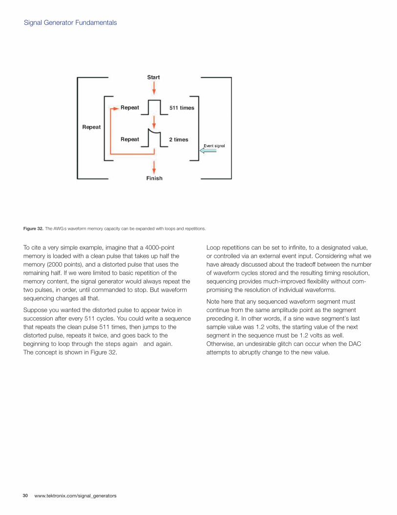
To cite a very simple example, imagine that a 4000-pointmemory is loaded with a clean pulse that takes up half thememory (2000 points), and a distorted pulse that uses theremaining half. If we were limited to basic repetition of thememory content, the signal generator would always repeat thetwo pulses, in order, until commanded to stop. But waveformsequencing changes all that.
Suppose you wanted the distorted pulse to appear twice insuccession after every 511 cycles. You could write a sequencethat repeats the clean pulse 511 times, then jumps to the distorted pulse, repeats it twice, and goes back to the beginning to loop through the steps again and again. The concept is shown in Figure 32.
Loop repetitions can be set to infinite, to a designated value,or controlled via an external event input. Considering what wehave already discussed about the tradeoff between the numberof waveform cycles stored and the resulting timing resolution,sequencing provides much-improved flexibility without com-promising the resolution of individual waveforms.
Note here that any sequenced waveform segment must continue from the same amplitude point as the segment preceding it. In other words, if a sine wave segment’s lastsample value was 1.2 volts, the starting value of the next segment in the sequence must be 1.2 volts as well.Otherwise, an undesirable glitch can occur when the DACattempts to abruptly change to the new value.
Figure 32. The AWG s waveform memory capacity can be expanded with loops and repetitions.
Signal Generator Fundamentals
www.tektronix.com/signal_generators 31
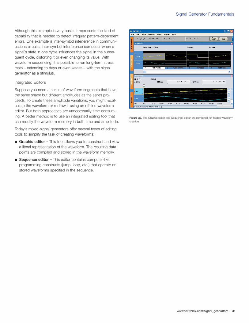
Although this example is very basic, it represents the kind ofcapability that is needed to detect irregular pattern-dependenterrors. One example is inter-symbol interference in communi-cations circuits. Inter-symbol interference can occur when asignal’s state in one cycle influences the signal in the subse-quent cycle, distorting it or even changing its value. Withwaveform sequencing, it is possible to run long-term stresstests – extending to days or even weeks – with the signal generator as a stimulus.
Integrated Editors
Suppose you need a series of waveform segments that havethe same shape but different amplitudes as the series pro-ceeds. To create these amplitude variations, you might recal-culate the waveform or redraw it using an off-line waveformeditor. But both approaches are unnecessarily time-consum-ing. A better method is to use an integrated editing tool thatcan modify the waveform memory in both time and amplitude.
Today’s mixed-signal generators offer several types of editingtools to simplify the task of creating waveforms:
Graphic editor – This tool allows you to construct and viewa literal representation of the waveform. The resulting data points are compiled and stored in the waveform memory.
Sequence editor – This editor contains computer-like programming constructs (jump, loop, etc.) that operate on stored waveforms specified in the sequence.
Figure 33. The Graphic editor and Sequence editor are combined for flexible waveformcreation.
32
Signal Generator Fundamentals
www.tektronix.com/signal_generators
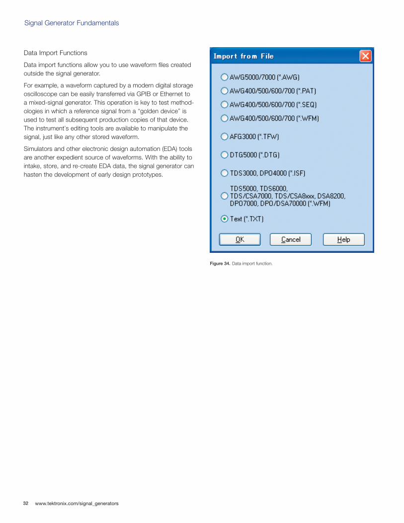
Data Import Functions
Data import functions allow you to use waveform files createdoutside the signal generator.
For example, a waveform captured by a modern digital storageoscilloscope can be easily transferred via GPIB or Ethernet toa mixed-signal generator. This operation is key to test method-ologies in which a reference signal from a “golden device” isused to test all subsequent production copies of that device.The instrument’s editing tools are available to manipulate thesignal, just like any other stored waveform.
Simulators and other electronic design automation (EDA) toolsare another expedient source of waveforms. With the ability tointake, store, and re-create EDA data, the signal generator canhasten the development of early design prototypes.
Figure 34. Data import function.
Signal Generator Fundamentals
www.tektronix.com/signal_generators 33
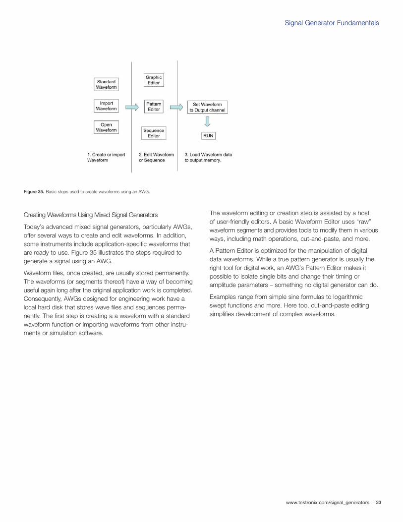
Creating Waveforms Using Mixed Signal Generators
Today’s advanced mixed signal generators, particularly AWGs,offer several ways to create and edit waveforms. In addition,some instruments include application-specific waveforms thatare ready to use. Figure 35 illustrates the steps required togenerate a signal using an AWG.
Waveform files, once created, are usually stored permanently.The waveforms (or segments thereof) have a way of becominguseful again long after the original application work is completed.Consequently, AWGs designed for engineering work have alocal hard disk that stores wave files and sequences perma-nently. The first step is creating a a waveform with a standardwaveform function or importing waveforms from other instru-ments or simulation software.
The waveform editing or creation step is assisted by a host of user-friendly editors. A basic Waveform Editor uses “raw”waveform segments and provides tools to modify them in variousways, including math operations, cut-and-paste, and more.
A Pattern Editor is optimized for the manipulation of digitaldata waveforms. While a true pattern generator is usually theright tool for digital work, an AWG’s Pattern Editor makes itpossible to isolate single bits and change their timing or amplitude parameters – something no digital generator can do.
Examples range from simple sine formulas to logarithmicswept functions and more. Here too, cut-and-paste editingsimplifies development of complex waveforms.
Figure 35. Basic steps used to create waveforms using an AWG.
34
Signal Generator Fundamentals
www.tektronix.com/signal_generators
The last step in setting up the AWG is to compile files wherenecessary (as with files from the Equation Editor) and store thecompiled files on the hard disk. The “Load” operation brings thewaveform into the AWG’s dynamic memory, where it is multiplexedand sent to the DAC before being output in its analog form.
These are the basic steps to produce a waveform on an AWG.As explained earlier, waveform files can be concatenated intoa sequence using a separate Sequence Editor, yielding a signalstream of almost unlimited length and any degree of complexity.
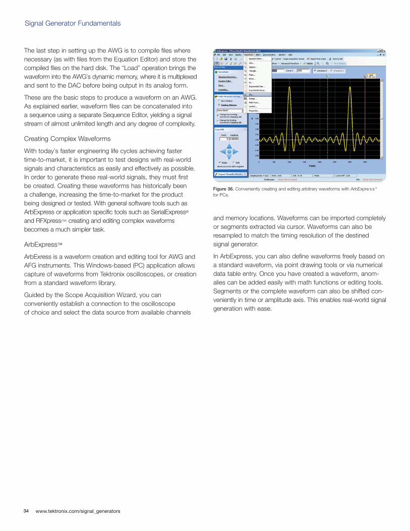
Creating Complex Waveforms
With today’s faster engineering life cycles achieving fastertime-to-market, it is important to test designs with real-worldsignals and characteristics as easily and effectively as possible.In order to generate these real-world signals, they must first be created. Creating these waveforms has historically been a challenge, increasing the time-to-market for the productbeing designed or tested. With general software tools such asArbExpress or application specific tools such as SerialExpress®
and RFXpress(TM) creating and editing complex waveformsbecomes a much simpler task.
ArbExpress™
ArbExress is a waveform creation and editing tool for AWG andAFG instruments. This Windows-based (PC) application allowscapture of waveforms from Tektronix oscilloscopes, or creationfrom a standard waveform library.
Guided by the Scope Acquisition Wizard, you can conveniently establish a connection to the oscilloscope of choice and select the data source from available channels
and memory locations. Waveforms can be imported completelyor segments extracted via cursor. Waveforms can also beresampled to match the timing resolution of the destined signal generator.
In ArbExpress, you can also define waveforms freely based ona standard waveform, via point drawing tools or via numericaldata table entry. Once you have created a waveform, anom-alies can be added easily with math functions or editing tools.Segments or the complete waveform can also be shifted con-veniently in time or amplitude axis. This enables real-world signalgeneration with ease.
Figure 36. Conveniently creating and editing arbitrary waveforms with ArbExpre s s “ for PCs.
SerialXpress®
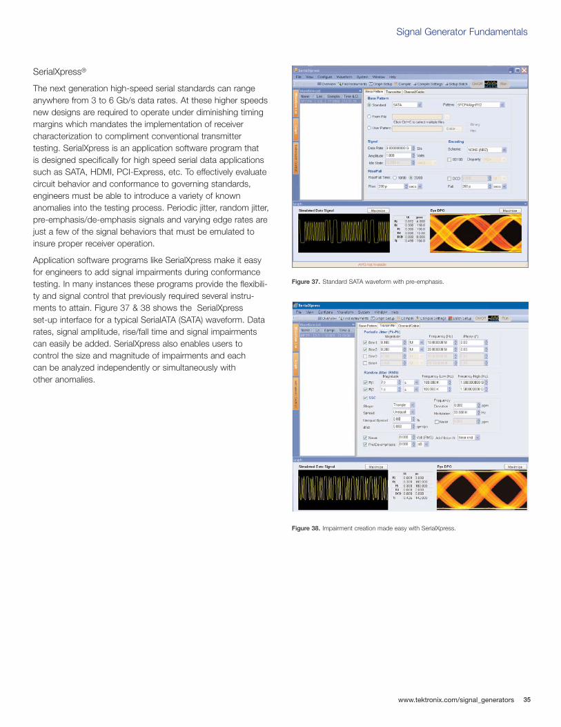
The next generation high-speed serial standards can rangeanywhere from 3 to 6 Gb/s data rates. At these higher speedsnew designs are required to operate under diminishing timingmargins which mandates the implementation of receiver characterization to compliment conventional transmitter testing. SerialXpress is an application software program that is designed specifically for high speed serial data applicationssuch as SATA, HDMI, PCI-Express, etc. To effectively evaluatecircuit behavior and conformance to governing standards,engineers must be able to introduce a variety of known anomalies into the testing process. Periodic jitter, random jitter,pre-emphasis/de-emphasis signals and varying edge rates arejust a few of the signal behaviors that must be emulated toinsure proper receiver operation.
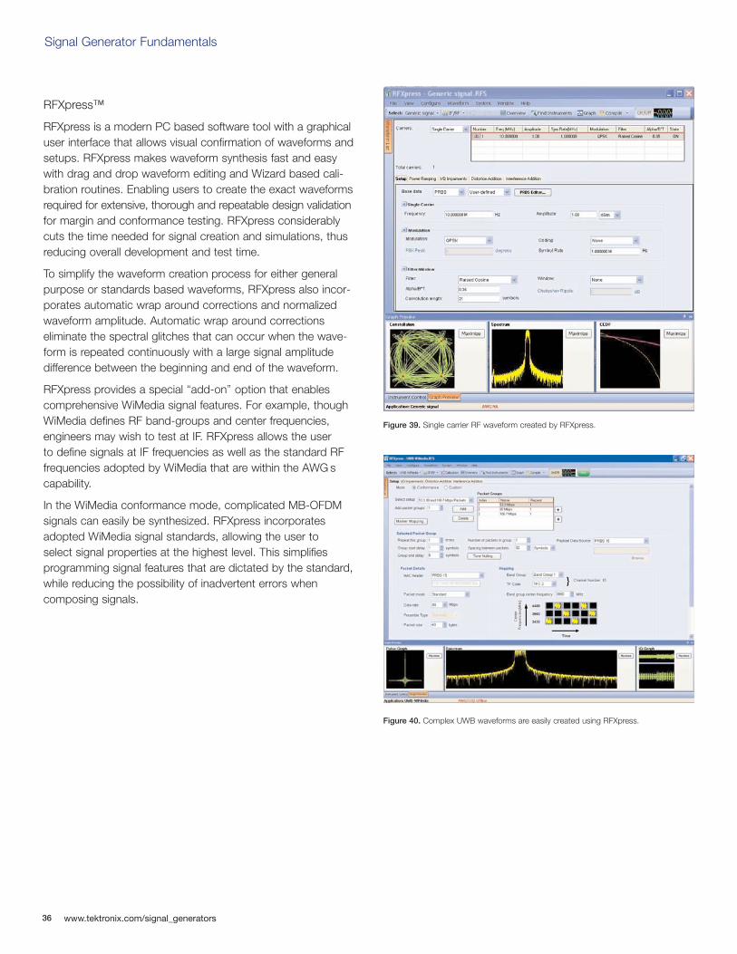
Application software programs like SerialXpress make it easyfor engineers to add signal impairments during conformancetesting. In many instances these programs provide the flexibili-ty and signal control that previously required several instru-ments to attain. Figure 37 & 38 shows the SerialXpress set-up interface for a typical SerialATA (SATA) waveform. Datarates, signal amplitude, rise/fall time and signal impairmentscan easily be added. SerialXpress also enables users to control the size and magnitude of impairments and each can be analyzed independently or simultaneously with other anomalies.
Signal Generator Fundamentals
www.tektronix.com/signal_generators 35
Figure 37. Standard SATA waveform with pre-emphasis.
Figure 38. Impairment creation made easy with SerialXpress.
36
RFXpress™
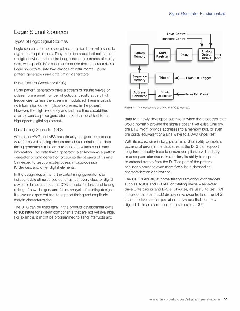
RFXpress is a modern PC based software tool with a graphicaluser interface that allows visual confirmation of waveforms andsetups. RFXpress makes waveform synthesis fast and easywith drag and drop waveform editing and Wizard based cali-bration routines. Enabling users to create the exact waveformsrequired for extensive, thorough and repeatable design validationfor margin and conformance testing. RFXpress considerablycuts the time needed for signal creation and simulations, thusreducing overall development and test time.
To simplify the waveform creation process for either generalpurpose or standards based waveforms, RFXpress also incor-porates automatic wrap around corrections and normalizedwaveform amplitude. Automatic wrap around corrections eliminate the spectral glitches that can occur when the wave-form is repeated continuously with a large signal amplitude difference between the beginning and end of the waveform.
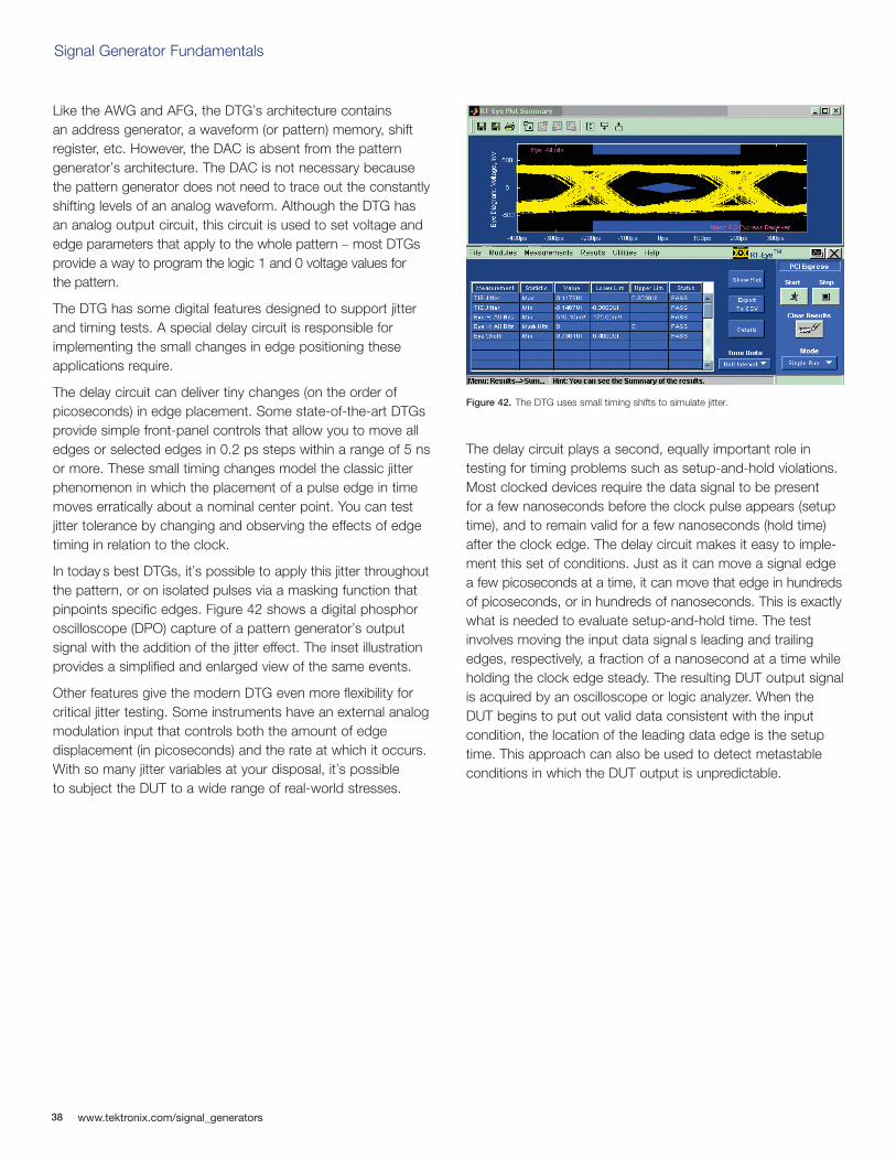
RFXpress provides a special “add-on” option that enablescomprehensive WiMedia signal features. For example, thoughWiMedia defines RF band-groups and center frequencies,engineers may wish to test at IF. RFXpress allows the user to define signals at IF frequencies as well as the standard RFfrequencies adopted by WiMedia that are within the AWG scapability.
In the WiMedia conformance mode, complicated MB-OFDMsignals can easily be synthesized. RFXpress incorporatesadopted WiMedia signal standards, allowing the user to select signal properties at the highest level. This simplifies programming signal features that are dictated by the standard,while reducing the possibility of inadvertent errors when composing signals.
Signal Generator Fundamentals
www.tektronix.com/signal_generators
Figure 40. Complex UWB waveforms are easily created using RFXpress.
Figure 39. Single carrier RF waveform created by RFXpress.
37
Signal Generator Fundamentals
www.tektronix.com/signal_generators
Logic Signal Sources
Types of Logic Signal Sources
Logic sources are more specialized tools for those with specificdigital test requirements. They meet the special stimulus needsof digital devices that require long, continuous streams of binarydata, with specific information content and timing characteristics.Logic sources fall into two classes of instruments – pulse pattern generators and data timing generators.
Pulse Pattern Generator (PPG)
Pulse pattern generators drive a stream of square waves orpulses from a small number of outputs, usually at very highfrequencies. Unless the stream is modulated, there is usuallyno information content (data) expressed in the pulses.However, the high frequency and fast rise time capabilities of an advanced pulse generator make it an ideal tool to testhigh-speed digital equipment.
Data Timing Generator (DTG)
Where the AWG and AFG are primarily designed to producewaveforms with analog shapes and characteristics, the datatiming generator’s mission is to generate volumes of binaryinformation. The data timing generator, also known as a patterngenerator or data generator, produces the streams of 1s and0s needed to test computer buses, microprocessor IC devices, and other digital elements.
In the design department, the data timing generator is anindispensable stimulus source for almost every class of digitaldevice. In broader terms, the DTG is useful for functional testing,debug of new designs, and failure analysis of existing designs.It s also an expedient tool to support timing and amplitudemargin characterization.
The DTG can be used early in the product development cycleto substitute for system components that are not yet available.For example, it might be programmed to send interrupts and
data to a newly developed bus circuit when the processor thatwould normally provide the signals doesn’t yet exist. Similarly,the DTG might provide addresses to a memory bus, or eventhe digital equivalent of a sine wave to a DAC under test.
With its extraordinarily long patterns and its ability to implantoccasional errors in the data stream, the DTG can supportlong-term reliability tests to ensure compliance with military or aerospace standards. In addition, its ability to respond to external events from the DUT as part of the patternsequence provides even more flexibility in demanding characterization applications.
The DTG is equally at home testing semiconductor devicessuch as ASICs and FPGAs, or rotating media – hard-disk drive write circuits and DVDs. Likewise, it’s useful to test CCDimage sensors and LCD display drivers/controllers. The DTG is an effective solution just about anywhere that complex digital bit streams are needed to stimulate a DUT.
Figure 41. The architecture of a PPG or DTG (simplified).
PatternMemory
ShiftRegister Delay
Level Control
Transient Control
SequenceMemory
AddressGenerator
Trigger
ClockOscillator
From Ext. Trigger
From Ext. Clock
AnalogOutputCircuit Out
38
Signal Generator Fundamentals
www.tektronix.com/signal_generators
Like the AWG and AFG, the DTG’s architecture contains an address generator, a waveform (or pattern) memory, shiftregister, etc. However, the DAC is absent from the patterngenerator’s architecture. The DAC is not necessary becausethe pattern generator does not need to trace out the constantlyshifting levels of an analog waveform. Although the DTG hasan analog output circuit, this circuit is used to set voltage andedge parameters that apply to the whole pattern – most DTGsprovide a way to program the logic 1 and 0 voltage values for the pattern.
The DTG has some digital features designed to support jitterand timing tests. A special delay circuit is responsible forimplementing the small changes in edge positioning theseapplications require.
The delay circuit can deliver tiny changes (on the order ofpicoseconds) in edge placement. Some state-of-the-art DTGsprovide simple front-panel controls that allow you to move alledges or selected edges in 0.2 ps steps within a range of 5 nsor more. These small timing changes model the classic jitterphenomenon in which the placement of a pulse edge in timemoves erratically about a nominal center point. You can testjitter tolerance by changing and observing the effects of edgetiming in relation to the clock.
In today s best DTGs, it’s possible to apply this jitter throughoutthe pattern, or on isolated pulses via a masking function thatpinpoints specific edges. Figure 42 shows a digital phosphoroscilloscope (DPO) capture of a pattern generator’s output signal with the addition of the jitter effect. The inset illustrationprovides a simplified and enlarged view of the same events.
Other features give the modern DTG even more flexibility forcritical jitter testing. Some instruments have an external analogmodulation input that controls both the amount of edge displacement (in picoseconds) and the rate at which it occurs.With so many jitter variables at your disposal, it’s possible to subject the DUT to a wide range of real-world stresses.
The delay circuit plays a second, equally important role in testing for timing problems such as setup-and-hold violations.Most clocked devices require the data signal to be present for a few nanoseconds before the clock pulse appears (setuptime), and to remain valid for a few nanoseconds (hold time)after the clock edge. The delay circuit makes it easy to imple-ment this set of conditions. Just as it can move a signal edgea few picoseconds at a time, it can move that edge in hundredsof picoseconds, or in hundreds of nanoseconds. This is exactlywhat is needed to evaluate setup-and-hold time. The testinvolves moving the input data signal s leading and trailingedges, respectively, a fraction of a nanosecond at a time whileholding the clock edge steady. The resulting DUT output signalis acquired by an oscilloscope or logic analyzer. When theDUT begins to put out valid data consistent with the inputcondition, the location of the leading data edge is the setuptime. This approach can also be used to detect metastableconditions in which the DUT output is unpredictable.
Figure 42. The DTG uses small timing shifts to simulate jitter.
Signal Generator Fundamentals
www.tektronix.com/signal_generators 39
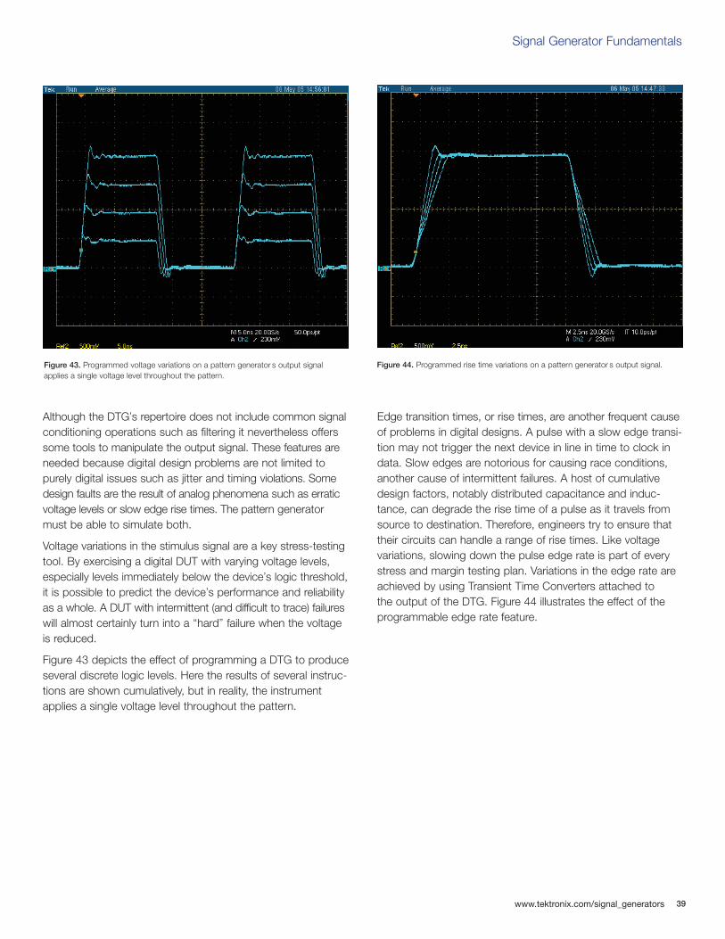
Although the DTG’s repertoire does not include common signalconditioning operations such as filtering it nevertheless offerssome tools to manipulate the output signal. These features areneeded because digital design problems are not limited topurely digital issues such as jitter and timing violations. Somedesign faults are the result of analog phenomena such as erraticvoltage levels or slow edge rise times. The pattern generatormust be able to simulate both.
Voltage variations in the stimulus signal are a key stress-testingtool. By exercising a digital DUT with varying voltage levels,especially levels immediately below the device’s logic threshold,it is possible to predict the device’s performance and reliabilityas a whole. A DUT with intermittent (and difficult to trace) failureswill almost certainly turn into a “hard” failure when the voltageis reduced.
Figure 43 depicts the effect of programming a DTG to produceseveral discrete logic levels. Here the results of several instruc-tions are shown cumulatively, but in reality, the instrumentapplies a single voltage level throughout the pattern.
Edge transition times, or rise times, are another frequent causeof problems in digital designs. A pulse with a slow edge transi-tion may not trigger the next device in line in time to clock indata. Slow edges are notorious for causing race conditions,another cause of intermittent failures. A host of cumulativedesign factors, notably distributed capacitance and induc-tance, can degrade the rise time of a pulse as it travels fromsource to destination. Therefore, engineers try to ensure thattheir circuits can handle a range of rise times. Like voltagevariations, slowing down the pulse edge rate is part of everystress and margin testing plan. Variations in the edge rate areachieved by using Transient Time Converters attached to the output of the DTG. Figure 44 illustrates the effect of theprogrammable edge rate feature.
Figure 43. Programmed voltage variations on a pattern generator s output signalapplies a single voltage level throughout the pattern.
Figure 44. Programmed rise time variations on a pattern generator s output signal.
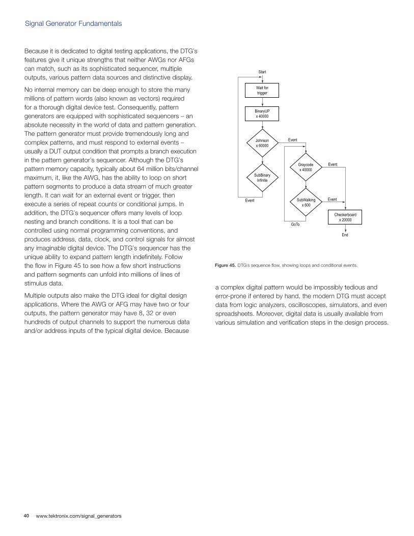
40
Signal Generator Fundamentals
www.tektronix.com/signal_generators
Because it is dedicated to digital testing applications, the DTG’sfeatures give it unique strengths that neither AWGs nor AFGscan match, such as its sophisticated sequencer, multiple outputs, various pattern data sources and distinctive display.
No internal memory can be deep enough to store the manymillions of pattern words (also known as vectors) required for a thorough digital device test. Consequently, pattern generators are equipped with sophisticated sequencers – anabsolute necessity in the world of data and pattern generation.The pattern generator must provide tremendously long andcomplex patterns, and must respond to external events –usually a DUT output condition that prompts a branch executionin the pattern generator’s sequencer. Although the DTG’s pattern memory capacity, typically about 64 million bits/channelmaximum, it, like the AWG, has the ability to loop on shortpattern segments to produce a data stream of much greaterlength. It can wait for an external event or trigger, then execute a series of repeat counts or conditional jumps. Inaddition, the DTG’s sequencer offers many levels of loop nesting and branch conditions. It is a tool that can be controlled using normal programming conventions, and produces address, data, clock, and control signals for almostany imaginable digital device. The DTG’s sequencer has theunique ability to expand pattern length indefinitely. Follow the flow in Figure 45 to see how a few short instructions and pattern segments can unfold into millions of lines of stimulus data.
Multiple outputs also make the DTG ideal for digital designapplications. Where the AWG or AFG may have two or fouroutputs, the pattern generator may have 8, 32 or even hundreds of output channels to support the numerous dataand/or address inputs of the typical digital device. Because
a complex digital pattern would be impossibly tedious anderror-prone if entered by hand, the modern DTG must acceptdata from logic analyzers, oscilloscopes, simulators, and evenspreadsheets. Moreover, digital data is usually available fromvarious simulation and verification steps in the design process.
Figure 45. DTG s sequence flow, showing loops and conditional events.
Wait fortrigger
BinaryUPx 40000
Checkerboardx 20000
Johnsonx 60000
SubBinaryInfinite
Graycodex 40000
SubWalkingx 600
Start
End
Event
Event
Event
GoTo
Event
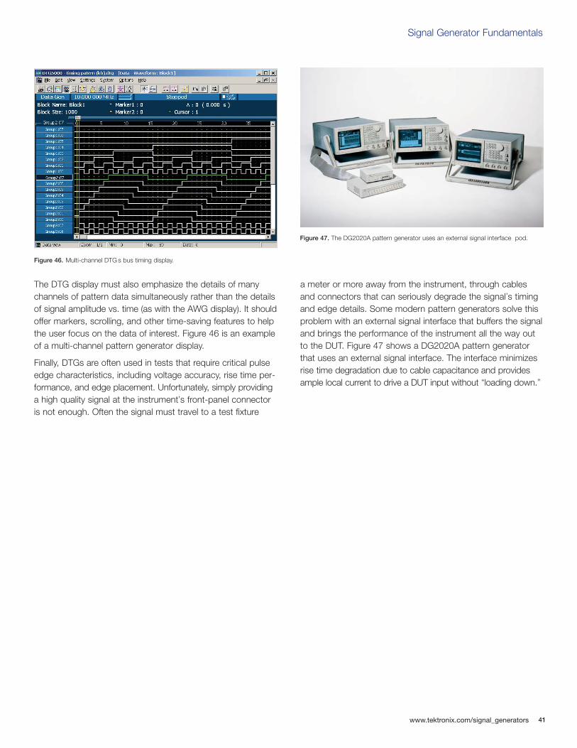
Signal Generator Fundamentals
www.tektronix.com/signal_generators 41
The DTG display must also emphasize the details of manychannels of pattern data simultaneously rather than the detailsof signal amplitude vs. time (as with the AWG display). It shouldoffer markers, scrolling, and other time-saving features to helpthe user focus on the data of interest. Figure 46 is an exampleof a multi-channel pattern generator display.
Finally, DTGs are often used in tests that require critical pulseedge characteristics, including voltage accuracy, rise time per-formance, and edge placement. Unfortunately, simply providinga high quality signal at the instrument’s front-panel connectoris not enough. Often the signal must travel to a test fixture
a meter or more away from the instrument, through cablesand connectors that can seriously degrade the signal’s timingand edge details. Some modern pattern generators solve thisproblem with an external signal interface that buffers the signaland brings the performance of the instrument all the way outto the DUT. Figure 47 shows a DG2020A pattern generatorthat uses an external signal interface. The interface minimizesrise time degradation due to cable capacitance and providesample local current to drive a DUT input without “loading down.”
Figure 46. Multi-channel DTG s bus timing display.
Figure 47. The DG2020A pattern generator uses an external signal interface pod.
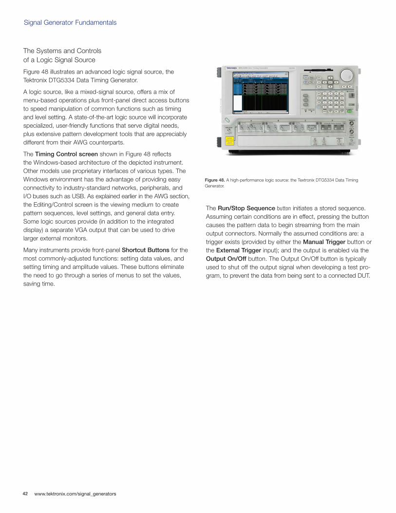
42
Signal Generator Fundamentals
www.tektronix.com/signal_generators
The Systems and Controls of a Logic Signal Source
Figure 48 illustrates an advanced logic signal source, theTektronix DTG5334 Data Timing Generator.
A logic source, like a mixed-signal source, offers a mix ofmenu-based operations plus front-panel direct access buttonsto speed manipulation of common functions such as timingand level setting. A state-of-the-art logic source will incorporatespecialized, user-friendly functions that serve digital needs,plus extensive pattern development tools that are appreciablydifferent from their AWG counterparts.
The Timing Control screen shown in Figure 48 reflects the Windows-based architecture of the depicted instrument.Other models use proprietary interfaces of various types. TheWindows environment has the advantage of providing easyconnectivity to industry-standard networks, peripherals, andI/O buses such as USB. As explained earlier in the AWG section,the Editing/Control screen is the viewing medium to createpattern sequences, level settings, and general data entry.Some logic sources provide (in addition to the integrated display) a separate VGA output that can be used to drive larger external monitors.
Many instruments provide front-panel Shortcut Buttons for themost commonly-adjusted functions: setting data values, andsetting timing and amplitude values. These buttons eliminatethe need to go through a series of menus to set the values,saving time.
The Run/Stop Sequence button initiates a stored sequence.Assuming certain conditions are in effect, pressing the buttoncauses the pattern data to begin streaming from the main output connectors. Normally the assumed conditions are: atrigger exists (provided by either the Manual Trigger button orthe External Trigger input); and the output is enabled via theOutput On/Off button. The Output On/Off button is typicallyused to shut off the output signal when developing a test pro-gram, to prevent the data from being sent to a connected DUT.
Figure 48. A high-performance logic source: the Textronix DTG5334 Data TimingGenerator.
Signal Generator Fundamentals
www.tektronix.com/signal_generators 43
The Menu/Navigation keys, the Scrolling Knob, and theNumeric Keypad are used for program development. TheMenu/Navigation keys open menus, while the Scrolling Knoband Keypad facilitate numeric data entry – timing values, binary data, and more.
Modular outputs are becoming the preferred solution to thediverse (and evolving) electrical requirements of today’s logicfamilies and bus architectures. Modules can be optimized forthe specific impedance, current, and voltage parameters of aparticular logic family, ensuring the highest possible precisionin the range of interest. Moreover, modular outputs spare thecost of unneeded modules. Instruments can be populatedwith as few as one output, or as many as 32.
Not seen on the front panel, but still important, is a brace ofsynchronization outputs on the back panel. These signals canbe used to synchronize acquisition instruments, the DUT itself,or even other signal sources. Note that a front-panel SyncOutput is also available for routine sync duties.
Performance Terms and Considerations
Digital signal sources share many performance parameterswith their analog counterparts, the AWG and AFG.
Data Rate
Data rate denotes the rate at which a digital signal source can output full cycles of binary information. The actual data bit within the cycle may or may not change state. The timebetween the boundaries of the cycle determines the data ratein megabits or gigabits per second.
Pattern Depth
Like the memory depth of an AWG, pattern depth determinesthe maximum amount of data that can be stored to supportpattern generation. A deeper memory can store more patternvariations. The digital signal source relies on sequencing tech-niques to create almost endless combinations of pattern words.
Vertical (Amplitude) Resolution
Vertical (amplitude) resolution refers to the smallest incrementof voltage change that can be programmed in the signalsource. In the digital context, this figure pertains to the logic levels that are set up for a given device family. Though nominally“fixed,” the levels can be modified within a certain range toallow stress testing (such as under-voltage tests). The verticalresolution determines the increments of this change.
Horizontal (Timing) Resolution
Horizontal (timing) resolution references the minimum incrementof time by which an edge, cycle time, or pulse width can be changed.
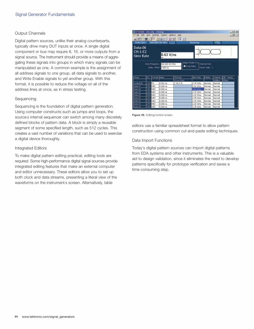
44
Signal Generator Fundamentals
www.tektronix.com/signal_generators
Output Channels
Digital pattern sources, unlike their analog counterparts, typically drive many DUT inputs at once. A single digital component or bus may require 8, 16, or more outputs from asignal source. The instrument should provide a means of aggre-gating these signals into groups in which many signals can bemanipulated as one. A common example is the assignment ofall address signals to one group, all data signals to another,and Write Enable signals to yet another group. With this format, it is possible to reduce the voltage on all of theaddress lines at once, as in stress testing.
Sequencing
Sequencing is the foundation of digital pattern generation.Using computer constructs such as jumps and loops, thesource s internal sequencer can switch among many discretelydefined blocks of pattern data. A block is simply a reusablesegment of some specified length, such as 512 cycles. Thiscreates a vast number of variations that can be used to exercisea digital device thoroughly.
Integrated Editors
To make digital pattern editing practical, editing tools arerequired. Some high-performance digital signal sources provideintegrated editing features that make an external computerand editor unnecessary. These editors allow you to set upboth clock and data streams, presenting a literal view of thewaveforms on the instrument s screen. Alternatively, table
editors use a familiar spreadsheet format to allow pattern construction using common cut-and-paste editing techniques.
Data Import Functions
Today’s digital pattern sources can import digital patterns from EDA systems and other instruments. This is a valuableaid to design validation, since it eliminates the need to developpatterns specifically for prototype verification and saves atime-consuming step.
Figure 49. Editing/control screen.
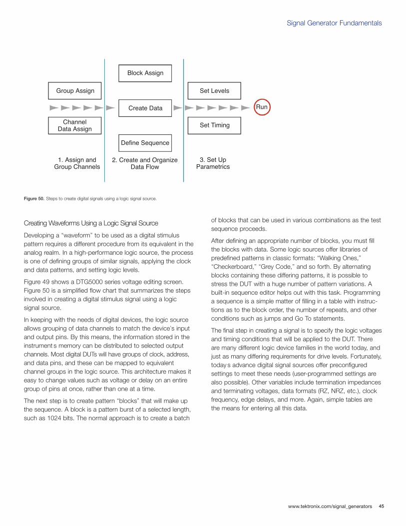
Signal Generator Fundamentals
www.tektronix.com/signal_generators 45
Creating Waveforms Using a Logic Signal Source
Developing a “waveform” to be used as a digital stimulus pattern requires a different procedure from its equivalent in theanalog realm. In a high-performance logic source, the processis one of defining groups of similar signals, applying the clockand data patterns, and setting logic levels.
Figure 49 shows a DTG5000 series voltage editing screen.Figure 50 is a simplified flow chart that summarizes the stepsinvolved in creating a digital stimulus signal using a logic signal source.
In keeping with the needs of digital devices, the logic sourceallows grouping of data channels to match the device’s inputand output pins. By this means, the information stored in theinstrument s memory can be distributed to selected outputchannels. Most digital DUTs will have groups of clock, address,and data pins, and these can be mapped to equivalent channel groups in the logic source. This architecture makes iteasy to change values such as voltage or delay on an entiregroup of pins at once, rather than one at a time.
The next step is to create pattern “blocks” that will make upthe sequence. A block is a pattern burst of a selected length,such as 1024 bits. The normal approach is to create a batch
of blocks that can be used in various combinations as the testsequence proceeds.
After defining an appropriate number of blocks, you must fillthe blocks with data. Some logic sources offer libraries of predefined patterns in classic formats: “Walking Ones,”“Checkerboard,” “Grey Code,” and so forth. By alternatingblocks containing these differing patterns, it is possible tostress the DUT with a huge number of pattern variations. Abuilt-in sequence editor helps out with this task. Programminga sequence is a simple matter of filling in a table with instruc-tions as to the block order, the number of repeats, and otherconditions such as jumps and Go To statements.
The final step in creating a signal is to specify the logic voltagesand timing conditions that will be applied to the DUT. Thereare many different logic device families in the world today, andjust as many differing requirements for drive levels. Fortunately,today s advance digital signal sources offer preconfigured settings to meet these needs (user-programmed settings arealso possible). Other variables include termination impedances and terminating voltages, data formats (RZ, NRZ, etc.), clockfrequency, edge delays, and more. Again, simple tables arethe means for entering all this data.
Figure 50. Steps to create digital signals using a logic signal source.
Group Assign
Block Assign
Create Data
Define Sequence
ChannelData Assign
1. Assign andGroup Channels
2. Create and OrganizeData Flow
3. Set UpParametrics
Set Levels
Set Timing
Run
46
Signal Generator Fundamentals
www.tektronix.com/signal_generators
ConclusionMany engineers look at tasks like troubleshooting and designverification as purely “measurement” challenges, and tend tothink reflexively of their oscilloscope or logic analyzer as thewhole solution to the problem. But these acquisition instru-ments have an important partner in their work: the stimulusinstrument – the signal generator.
Stimulus and acquisition instruments together make up acomplete solution that can drive a device-under-test with complex real-world signals and acquire the resulting outputs.The oscilloscope is the industry-standard tool for acquisition.But only with a signal generator can engineers really controlwhat goes into the device. And that is often a necessity formaking sense of what comes out of the device.
Similarly, the signal generator makes margin testing and characterization possible. Working with a signal generator andan oscilloscope or logic analyzer, engineers can explore thelimits of their design’s performance – introducing deliberatestresses with the source and measuring the results with theoscilloscope, or capturing data with the logic analyzer whendigital errors occur.
In applications ranging from disk drive design to telecommu-nications conformance testing, the signal generator and the acquisition instruments work together as a completemeasurement solution.
Signal Generator Fundamentals
www.tektronix.com/signal_generators 47
GlossaryAberration – Overshoot or undershoot in a waveform.
Agility – The ability to change quickly and cleanly from onefrequency to another.
Aliasing – The intrusion of distorted conversion by-productsinto the frequency range of interest.
Amplitude – The magnitude of a quantity or strength of a signal. In electronics, amplitude usually refers to either voltageor power.
Amplitude Modulation (AM) – A type of analog modulation inwhich amplitude variations embed lower-frequency informationinto a carrier signal of higher frequency; most commonly usedin broadcast communications.
Amplitude Resolution – See Vertical Resolution.
Amplitude Shift Keying (ASK) – A type of digital modulationin which the digital modulating signal causes the output frequency to switch between two amplitudes.
Analog Signal – A signal with continuously variable voltages.
Analog-to-Digital Converter (ADC) – A digital electroniccomponent that converts continuous analog signals into proportional discrete binary (digital) values.
Arbitrary – A waveform defined by individual preference or convenience rather than by the intrinsic nature of the signal generator.
Arbitrary/Function Generator (AFG) – A type of analog/mixed-signal generator that produces stable waveforms in standard shapes.
Arbitrary Waveform Generator (AWG) – A type of analog/mixed-signal generator in which an output of the arbitrary analogsignals created on memory is possible; a sophisticated play-back system that delivers waveforms based on stored digitaldata that describes the constantly changing voltage levels ofan AC signal.
Attenuation – A decrease in signal amplitude during its transmission from one point to another.
Bandwidth – A frequency range, usually limited by –3 dB.
Block – A pattern burst of a selected length, such as 1024 bits, that comprises a digital sequence output by a logic signal source.
Characterization – A common application in which a signalgenerator is used to determine the operating limits of a component,device or system; an application in which stress testing, ormargin testing, is a part of the activity conducted.
Clock Generator – A signal generator that can output only a rectangle wave; used primarily as a clock source.
Clock Rate – See Sample Rate.
Complementary Output – An output that uses two signalpaths to carry copies of the same signal in equal amplitude,with one signal inverted.
Continuous Mode – An operating mode within a signal gen-erator in which the output begins immediately, beginning at thehead of the waveform or sequence and repeating until turned off.
Cursor – An on-screen marker that you can align with a waveform to make more accurate measurements; in a signalgenerator, a cursor is used to select an area of a waveformbetween which the waveform can be modified.
Damped Sine Wave – A type of sine wave in which a circuitoscillates from an impulse, and then winds down over time.
Data Pattern Generator – A type of signal generator thatgenerates single or multiple streams of digital patterns; alsoknown as a pattern generator or data generator.
48
Signal Generator Fundamentals
www.tektronix.com/signal_generators
Data Rate – The rate at which a digital signal generator can output full cycles of binary information, usually specified interms of megabits or gigabits per second.
DC Accuracy – The difference of the set-up voltage and actual output voltage.
Delay – The difference in timing between two otherwise similarsignals; also known as phase shift.
Delayed Non-Return-to-Zero (DNRZ) – A common digitalpattern in which the waveform switches to a "1" after a specified time delay when a valid bit occurs in the cycle andstays at that value until the next cycle boundary, assuming that the cycle originated with a binary "0".
Device-under-test (DUT) – A device for measuring; synonymous with a unit-under-test (UUT).
Differential Output – An output that uses two signal paths to carry copies of the same signal of equal amplitude and one signal path is inverted where the amplitude is measuredrelative to each other and not to ground.
Digital Pattern – Multiple synchronized pulse streams thatcomprise "words" of data that may be 8, 12, 16 or more bits wide.
Digital Signal – A signal whose voltage samples are represented by discrete binary numbers.
Digital Waveform Generator – A type of signal generator thatoutputs digital patterns; also known as a logic signal source.
Digital-to-Analog Converter (DAC) – A digital electroniccomponent that converts discrete binary values into an electrical signal.
Direct Digital Synthesizer (DDS) Technology – Technologythat synthesizes waveforms by using a single clock frequencyto spawn any frequency within the instrument’s range; determines the rate at which samples are clocked out of a signal generator’s memory.
Distortion – A by-product of circuit realities, like distributedcapacitance, crosstalk, and more.
Duty Cycle – The variation of a wave or pulse in which thehigh and low time intervals are not of equal length; the ratio ofthe positive duration of a pulse to its negative or zero duration.
Equation Editor – An integrated math tool within a signal generator that allows you to enter variables and operators; the instrument then checks the syntax, and compiles andstores the resulting waveform.
Event Input – Used in conjunction with the sequencing func-tion of a signal generator. Upon receiving an event input signal(a TTL logic signal) the signal generator will jump to the nextline or waveform in a sequence.
Fall Time – Amount of time required for a pulse edge to makea transition to a state opposite its current level; in the case ofrise time, from low level to high level and, in the case of falltime, from high level to low level.
Filtering – The process by which a signal generator removesselected bands of frequency from a signal; can be used toprevent unwanted aliasing distortion in the DUT output.
Flatness – The degree which changes level with output frequency when outputting a sine wave.
Frequency – The number of times a signal repeats in onesecond, measured in Hertz (cycles per second). Frequencyequals 1/period.
Signal Generator Fundamentals
www.tektronix.com/signal_generators 49
Frequency Modulation (FM) – A type of analog modulation inwhich frequency variations embed lower-frequency informationinto a carrier signal of higher frequency; most commonly usedin broadcast communications.
Frequency Shift Keying (FSK) – A type of digital modulationin which the carrier switches between two frequencies, itscenter frequency and an offset frequency.
Function Generator (FG) – A type of signal generator that outputs fundamental waves, such as a sine wave or a rectangle wave.
Gigahertz (GHz) – 1,000,000,000 Hertz; a unit of frequency.
Glitch – An intermittent, high-speed error in a circuit or waveform.
Graphic Editor – An integrated tool within a signal generatorthat allows you to construct and view a literal representation ofthe waveform; the resulting data points are then compiled andstored in the waveform memory.
Horizontal Resolution – The smallest time increment that canbe used to create waveforms; the minimum increment of timeby which an edge, cycle time, or pulse width can be changed.
Horizontal System – Within a signal generator, the systemthat defines the frequency of the output signal by controllingthe sample rate.
Integrated Editor – An integrated editing tool within a signalgenerator that enables easy editing and modification of wave-forms in both time and amplitude.
Inter-symbol Interference – The distortion or altercation of asignal within one cycle caused by the influence of a signal sstate in the preceding cycle.
Jitter – A type of impairment that indicates that a cycle or frequency is not stabilized.
Kilohertz (kHz) – 1,000 Hertz; a unit of frequency.
Logic Analyzer – An instrument used to make the logic statesof many digital signals visible over time; an instrument thatanalyzes digital data and can represent the data as real-timesoftware execution, data flow values, state sequences, etc.
Logic Signal Source – A type of signal generator that outputs digital patterns, such as a pulse or pattern generator.
Margin Testing – A common application in which a signalgenerator is used to stress components, devices or systemswith impairments, such as jitter and timing violations, to deter-mine their operating limits, also known as stress testing.
Marker – The auxiliary output of a signal generator that is sep-arated from its main outputs; an auxiliary digital channel thatcan be used as a trigger signal for the DUT; an auxiliary digitalchannel that can be used to output a serial digital pattern.
Marker Output – A type of digital output that provides a binarysignal that is synchronous with the main analog output signal,typically driven from a memory that is independent of the mainwaveform memory.
Megahertz (MHz) – 1,000,000 Hertz; a unit of frequency.
Megasamples per second (MS/s) – A sample rate unit equalto one million samples per second.
50
Signal Generator Fundamentals
www.tektronix.com/signal_generators
Memory Depth – The number of waveform points used tocreate a record of a signal, which determines the maximumamount of waveform data (equivalent to time) that can bestored by an analog/mixed-signal generator.
Microsecond (µs) – A unit of time equivalent to 0.000001 seconds.
Millisecond (ms) – A unit of time equivalent to 0.001 seconds.
Mixed Signal Generator – A type of signal generator, such as an arbitrary waveform generator or arbitrary/function gener-ator, that outputs both analog waveforms and digital patterns.
Modulated Signal – A signal in which amplitude, phase, and/or frequency variations embed lower-frequency informationinto a carrier signal of higher frequency.
Nanosecond (ns) – A unit of time equivalent to 0.000000001 seconds.
Noise – An unwanted voltage or current in an electrical circuit.
NRZ (Non-Return-to-Zero) – A common digital pattern inwhich the waveform switches to a "1" when a valid bit occursin the cycle and stays at that value until the next cycle boundary,assuming that the cycle originated with a binary "0".
Nyquist Sampling Theorem – A theorem that states that thesampling frequency, or clock rate, must be at least twice thatof the highest frequency component of the sampled signal toensure accurate signal reproduction.
Offset – DC component of a signal that contains both AC andDC values; voltage between circuit ground and the center of asignal s amplitude.
Offset Level – The vertical displacement (in volts) of a waveform from its zero or ground level.
Output Signal – The waveform, pattern, or sequence file thathas been loaded into memory and given a run command; thesignal that passes through the front-panel output connectors.
Parallel Digital Output – A type of digital output that takesdigital data from the same memory as the signal generator’s main analog output and stores the digital equivalent of thewaveform sample value present on the analog output.
Pattern – See Digital Pattern.
Pattern Depth – The number of waveform points used to create a record of a signal, which determines the maximumamount of data (equivalent to time) that can be stored by alogic signal source to support pattern generation.
Pattern Editor – An integrated editing tool within a signal generator that makes it possible to modify and edit patterns in both time and amplitude.
Pattern Generator – A type of logic signal source that generates the digital pattern of many channels; also known as a data generator.
Peak (Vp ) – The maximum voltage level measured from a zeroreference point.
Peak-to-peak (Vp-p ) – The voltage measured from the maximum point of a signal to its minimum point.
Period – The amount of time it takes a wave to complete onecycle. The period equals 1/frequency.
Phase – The amount of time that passes from the beginningof a cycle to the beginning of the next cycle, measured in degrees.
Phase Modulation (PM) – A type of analog modulation inwhich phase variations embed lower-frequency informationinto a carrier signal of higher frequency; most commonly usedin broadcast communications.
Phase Shift – The difference in timing between two otherwisesimilar signals, also known as delay.
Phase Shift Keying (PSK) – A type of digital modulation inwhich the carrier switches between two phase settings.
Polarity – The direction in which current flows relative to itszero or ground level; usually refers to the starting direction,positive or negative, of a waveform.

Signal Generator Fundamentals
www.tektronix.com/signal_generators 51
Pseudo-random Bit Stream (PRBS) – A set of sequences,which consists of a stream of numbers that appear randombut follow a predictable mathematical pattern, repeated at arandom rate; used to create random noise in digital systems.
Pseudo-random Word Stream (PRWS) – A word stream thatdefines how multiple pseudorandom bit streams are presentedacross all of the signal generator’s parallel outputs, often usedwhen testing serializers or multiplexers.
Pulse – A common waveform shape that has a fast risingedge, a width, and a fast falling edge.
Pulse Pattern Generator – A type of logic signal source thatcan drive a stream of square waves or pulses from a smallnumber of outputs, usually at very high frequencies. Also known as a pulse generator.
Pulse Timing Generator – Similar to a Pulse Generator, with additional control over pulse timing such as delay or inter-channel skew. May also include parametric control over output signal voltage and rise time.
Pulse Train – A collection of pulses traveling together.
Pulse Width – The amount of time the pulse takes to go fromlow to high and back to low again, conventionally measured at50% of full voltage.
Pulse Width Modulation (PWM) – A type of digital modulationin which the modulating signal causes the active pulse widthof the pulse to vary, applicable to pulse waveforms only; commonly used in digital audio systems.
Quadrature (IQ) Modulation Technology – A type of modulation in which two carriers, an in-phase (I) waveform and a quadrature-phase (Q) waveform, are combined andtransmitted over one channel, then separated and demodulatedat the receiving end; commonly found in today’s wireless communications networks.
Ramps – Transitions between voltage levels of sine waves thatchange at a constant rate.
Record Length – The number of waveform points used tocreate a record of a signal, referred to as memory depth inanalog/mixed-signal generators and pattern depth in logic signal generators.
Rectangular Wave – A wave in which the switching charac-teristics are similar to those of a square wave, except that thehigh and low time intervals are not of equal length.
Region Shift – A function found within an analog/mixed-signalgenerator that shifts a specified edge of a waveform either rightor left, toward or away from the programmed center value,making it possible to create simulated jitter conditions andother tiny edge placement changes that exceed the resolutionof the instrument.
Replication – A method used to develop a waveform for use by a signal generator that involves capturing an existing signal on an oscilloscope and sending it to the signal generator for reproduction.
Return-to-One (R1) – A common digital pattern in which thewaveform switches to a “0” when a valid bit is present andthen switches back to a “1” within the same cycle, assumingthat the cycle originated with a binary “1;” the inverse of RZ.
Return-to-Zero (RZ) – A common digital pattern in which thewaveform switches to a “1” when a valid bit is present andthen switches back to a “0” within the same cycle, assumingthat the cycle originated with a binary “0.”
52
Signal Generator Fundamentals
www.tektronix.com/signal_generators
Rise Time – Amount of time required for a pulse edge tomake a transition to a state opposite its current level; in thecase of rise time, from low level to high level and, in the caseof fall time, from high level to low level.
Sampling – The process used to define a signal using samples, or data points, that represent a series of voltagemeasurements along the slope of a waveform.
Sample Point – Data points that represent a series of voltagemeasurements along the slope of a waveform; the raw datafrom an ADC used to calculate waveform points.
Sample Rate – The rate at which an analog/mixed-signal generator can output full waveform cycles, usually specified in terms of megasamples or gigasamples per second; alsoknown as clock rate or sampling frequency.
Sawtooth Wave – A wave in which the voltage ramps upslowly and evenly to a peak in each cycle, then falls off quickly.
Screen – The surface of the display upon which the visiblepattern is produced — the display area.
Sequence Editor – An integrated tool within a signal generatorthat contains computer-like programming instructions (jumps,loops, etc.) that reside in a sequence memory separate fromthe waveform memory and cause specified segments of thewaveform memory to repeat.
Sequence Repeat Counter – A control mechanism used in the sequencing process to determine the number of operational cycles and the order in which they appear.
Sequencing – The process by which a signal generator createswaveforms of almost unlimited length by storing a large number of "virtual" waveform cycles in the instrument’s memory and repeating them according to the instructions of the sequence editor.
Signal Fidelity – The accurate reconstruction of a signal,determined by the systems and performance considerations of the stimulus or acquisition instrument.
Signal Modulation – A process in which signal amplitude,phase and/or frequency variations embed lower-frequencyinformation into a carrier signal of higher frequency.
Signal Source or Signal Generator – A test device used toinject a signal into a circuit input; the circuit’s output is thenread by an oscilloscope or logic analyzer; also known as a signal generator.
Simulation – A technique used by a signal generator to output a waveform that mimics the output of a device for use in testing another device.
Sine Wave – A common curved wave shape that is mathematically defined.
Single-ended Output – An output that uses one path to carrya signal, relative to ground.
Slope – On a graph or an instrument’s screen, the ratio of a vertical distance to a horizontal distance. A positive slopeincreases from left to right, while a negative slope decreasesfrom left to right.
Spurious Free Dynamic Range (SFDR) – The ratio of thespecified maximum signal level capability of the signal generatorto its noise.

Signal Generator Fundamentals
www.tektronix.com/signal_generators 53
Square Wave – A common wave shape consisting of repeatingsquare pulses; a voltage that switches between two fixed voltage levels at regular intervals.
Step – A waveform that shows a sudden change in voltage.
Substitution – A method used to develop a waveform for useby a signal generator that involves creating and/or modifying adefined signal to substitute for a signal from unavailable circuitry.
Sweep Generator – A function generator that can vary the frequency of a signal, typically a sine wave, over a specified time period.
Swept Sine Wave – A type of sine wave that increases in frequency over some period of time.
Table Editor – An integrated tool within a logic signal sourcethat uses a spreadsheet-like format to allow pattern constructionusing common cut-and-paste techniques.
Timing Editor – An integrated tool within a logic signal sourcethat allows setup of both clock and data streams, presenting a literal view of the waveforms on the instrument s screen.
Timing Resolution – See Horizontal Resolution.
Transducer – A device that converts a specific physical quantity such as sound, pressure, strain, or light intensity into an electrical signal.
Triangle Wave – A wave in which the voltage exhibits symmetrical rise and fall times.
Trigger – An external signal or front-panel button that tells the signal generator when to begin outputting a specified signal.
Trigger Level – The minimum input value, in + or — volts,required by an external trigger input signal to start instrument operation.
Trigger System – Within a signal generator, the system that defines the conditions under which the instrument willcommence driving signals through its output, assuming it isnot running in a continuous mode.
Unit-under-test (UUT) – A unit for measuring; synonymouswith a device-under-test (DUT).
Verification – A common application in which a signal generator isused to determine whether or not a component, device or systemoperates as predicted, and conforms to industry standards.
Vertical System – Within a signal generator, the system thatdefines the amplitude and offset level of the output signal.
Vertical Resolution – The smallest increment of voltage changethat can be programmed in a signal generator; the binary wordwidth, in bits, of the instrument s DAC, which defines theamplitude accuracy and distortion of the reproduced waveform.
Volt – The unit of electric potential difference.
Voltage – The difference in electric potential, expressed involts, between two points.
Wave – The generic term for a pattern that repeats over time. Common types include: sine, square, rectangular, saw-tooth, triangle, step, pulse, periodic, non-periodic, synchronous, asynchronous.
Waveform – A graphic representation of a wave’s activity andits variation over time.
Waveform Point – A digital value that represents the voltageof a signal at a specific point in time, calculated from samplepoints and stored in memory.
For Further InformationTektronix maintains a comprehensive, constantly expandingcollection of application notes, technical briefs and otherresources to help engineers working on the cutting edge oftechnology. Please visit www.tektronix.com
Copyright © 2009, Tektronix. All rights reserved. Tektronix products are covered by U.S. and foreign patents, issued and pending. Information in this publicationsupersedes that in all previously published material. Specification and pricechange privileges reserved. TEKTRONIX and TEK are registered trademarks of Tektronix, Inc. All other trade names referenced are the service marks, trademarks or registered trademarks of their respective companies. 3/09 JS/WWW 76W-16672-5_edu
Contact Tektronix Service:ASEAN / Australasia (65) 6356 3900
Austria +49 (0)221 94 77 612
Balkan, Israel, South Africa and other ISE Countries +49 (0)221 94 77 612
Belgium 078 160 164
Brazil, South/Central America, Mexico, Caribean (52) 55 5424 7900
Canada 1 (800) 833-9200 Opt. 2
Central East Europe, Ukraine, Greece and Baltics +49 (0)221 94 77 612
Denmark +45 8 088 1404
Finland 0800 1 12659
France & North Africa +33 (0) 1 69 86 81 80
Germany +49 (0)221 94 77 612
Hong Kong (852) 2585-6688
India 91 (80) 2277 5577
Italy +39 02 25086511
Japan +81(0) 463 70 5601
Luxembourg+49 (0) 221 9477 616
Middle East, Asia and North Africa +49 (0) 221 9477 619
The Netherlands 0900 2021 795
Norway +49 (0)221 9477 619
People’s Republic of China - Beijing 86 (10) 6238 5060
People’s Republic of China - Shanghai 86 (21) 38960832
Poland +49 (0)221 9477 619
Portugal +49 (0)221 9477 619
Republic of Korea 82 (2) 6917 5002
Russia & CIS +49 (0) 221 94 77 612
Singapore (65) 6356-3900
Spain 901 988 095
Sweden 020 088 0369
Switzerland +49 (0)221 94 77 612
Taiwan 886 (2) 2722-9622
United Kingdom & Eire +44 (0) 1344 392 240
USA 1 (800) 833-9200 Opt. 2
For other areas contact Tektronix, Inc. at: 1 (503) 627-7111
Last Updated February 20, 2008