Embed Size (px)
Citation preview

MG3710AVector Signal Generator100 kHz to 2.7 GHz100 kHz to 4.0 GHz100 kHz to 6.0 GHz
Product Brochure

2 Product Brochure l MG3710A
The MG3710A is a vector signal generator with 6-GHz upper frequency limit and 160-MHz∗/120-MHz wide RF modulation baseband generator. It outputs various radio systems signals for cellular communications, such as LTE FDD/TDD, W-CDMA, GSM as well as narrowband communications, such as WLAN, WiMAX, Bluetooth and GPS.
Cuts Equipment CostsThe dual waveform memory cuts equipment costs for tests, such as ACS, Blocking and IM, which require two modulation signal sources.The dual RF cuts MIMO equipment costs and reduces workloads for phase synchronization between equipment. It is important for tests using separate signals, such as MSR and multi-band.
Improves YieldThe excellent signal generator ACLR and SSB phase noise reduces the effect on wideband and narrow-band measurements to improve test margins and yields.
–71 dBc @W-CDMA, TestModel1, 64DPCH, 2 GHz<–140 dBc/Hz (nom.) @100 MHz, 20 kHz offset, CW
Cuts Tact TimeThe List/Sweep mode switches the frequency and level faster than 600 µs. Moreover, the 4-GB waveform memory upgrade can load many waveform patterns while instantaneous switching eliminates time wasted reloading waveform patterns.
Multi-Band Multi-System Multi-Channel
Cut Costs for New Wireless Tests
Dual Waveform MemoryOne RF output supports two waveform memories!Combine wanted and interference signals in baseband and output at one RF.
Dual RFOne unit supports two RF outputs! Ideal for Multi-band, MIMO and MSR evaluations.
RF Modulation Bandwidth: 160 MHz∗/120 MHzCan generate and output signals for 160-MHz bandwidth max. wireless LAN (IEEE802.11ac) and for 120-MHz bandwidth.
∗: Supports firmware version 2.00.00 and later. Can generate 160-MHz bandwidth signals (Wireless LAN IEEE802.11ac) only when using MX370111A WLAN IQproducer and MX370111A-002 802.11ac (160 MHz) option. The latest version can be downloaded from the Anritsu homepage. <https://www1.anritsu.co.jp/Download/MService/Login.asp>

Product Brochure l MG3710A 3
∗1: 1stRF ARB memory size256 MB × 1 pc = 64 Msamples (Std.)1 GB × 1 pc = 256 Msamples × 1 pc (Opt. 045)1 GB × 2 pcs = 256 Msamples × 2 pcs (Opt. 045 + Opt. 048)4 GB × 1 pc = 1024 Msamples × 1 pc (Opt. 046)4 GB × 2 pcs = 1024 Msamples × 2 pcs (Opt. 046 + Opt. 048)
∗2: 2ndRF ARB memory size256 MB × 1 pc = 64 Msamples (Std.)1 GB × 1 pc = 256 Msamples × 1 pc (Opt. 075)1 GB × 2 pcs = 256 Msamples × 2 pcs (Opt. 075 + Opt. 078)4 GB × 1 pc = 1024 Msamples × 1 pc (Opt. 076)4 GB × 2 pcs = 1024 Msamples × 2 pcs (Opt. 076 + Opt. 078)
etc.

4 Product Brochure l MG3710A
Dual RF & Dual Waveform Memory● One Unit Supports Two RF Outputs Max.• Frequency Range
1stRF: 100 kHz to 2.7/4.0/6.0 GHz [Opt. 032/034/036]2ndRF: 100 kHz to 2.7/4.0/6.0 GHz [Opt. 062/064/066]
• Independent Baseband and RF Outputs● Output Two Signals from One RF Out [Opt. 048/078]The baseband signal combine option installs two waveform memories for either the 1stRF (or 2ndRF) SG to combine two waveform patterns as the baseband for output, eliminating the need for two separate and expensive vector signal generators.
Wanted Signal + Interfere SignalWanted Signal + Delayed Signal, etc.
Basic Performance● ACLR Performance
–71 dBc @W-CDMA, TestModel1, 64 DPCH, 2 GHz
High All-purpose Baseband Performance● Wide Vector Modulation Bandwidth160 MHz∗/120 MHz (using Internal baseband signal generator)160 MHz (using External IQ input)∗: Supports firmware version 2.00.00 and later. Can generate 160-MHz
bandwidth signals (Wireless LAN IEEE802.11ac) only when using MX370111A WLAN IQproducer and MX370111A-002 802.11ac (160 MHz) option.
● Large-capacity Waveform Memory64 Msamples [with 1stRF, 2ndRF]256 Msamples [Opt. 045/075]1024 Msamples [Opt. 046/076]
● Arbitrary Waveform GenerationASCII IQ sample data created using general-purpose signal generation software (such as MATLAB) can be converted to waveform patterns for the MG3710A. Data produced during R&D simulations can be converted using IQproducer.
Expandability● BER Test Function [Opt. 021]This option measures BER using Data/Clock/Enable demodulated at the DUT to display the results on the MG3710A screen.• Input bit rate: 100 bps to 40 Mbps● Analog/Pulse Modulation Functions [Standard]∗: Supports built-in analog modulation (AM/FM/ΦM) functions and
pulse modulation (PM) functions. Adding additional analog modulation input options (Opt. 050/080) supports modulation by external signal input.
● AWGN Generator [Opt. 049/079]This options generates AWGN internally for the required waveform.• Absolute CN Ratio: ≤40 dB
● USB Power Sensors [Sold separately]Up to two USB power sensors can be connected to the MG3710A and the results are displayed on the MG3710A screen.• Frequency Range: 50 MHz to 6 GHz [MA24106A]
10 MHz to 18 GHz [MA24118A] 10 MHz to 26 GHz [MA24126A] etc.
● Local Signal I/O for MIMO Signal Source [Opt. 017]Local signals, baseband clocks and trigger signals can be shared between up to four MG3710A units to output phase coherency signals with synchronized signal output timing for configuring even 8×8 MIMO systems.
Key Features
W-CDMA ACLR (1 Carrier)Waveform Pattern (TestModel1, 64DPCH)
● High-power Output [Opt. 041/071]+23 dBm @CW, 400 MHz to 3 GHz
● High-speed Switching< 600 µs @List/Sweep mode
● High Level AccuracyAbsolute Level Accuracy: ±0.5 dBLinearity: ±0.2 dB (typ.)
● Choice of Reference Oscillators• Standard
Aging rate ±1 × 10⁻⁶/year, ±1 × 10⁻⁷/day• High Stability Reference Oscillator [Opt. 002]
Aging rate ±1 × 10⁻⁷/year, ±1 × 10⁻⁸/day• Rubidium Reference Oscillator [Opt. 001]
Aging rate ±1 × 10⁻¹⁰/month
● SSB Phase Noise Performance<–140 dBc/Hz (nom.) @100 MHz, 20-kHz offset, CW<–131 dBc/Hz (typ.) @1 GHz, 20-kHz offset, CW <–125 dBc/Hz (typ.) @2 GHz, 20-kHz offset, CW
(meas)

Product Brochure l MG3710A 5
Operability● Simple Touch-panel OperationTouching the easy-to-use GUI with hierarchical menus fetches related function and numeric input keys for simple fast settings.
● Signal Flowcharts with Signal Block DiagramsTwo intuitive Hardware Block Chart and ARB Info screens make it easy to grasp settings, data and signal paths at a glance.
● Frequency Channel TableA built-in channel table with presettings for popular communications systems simplifies frequency settings by using channel numbers.
Connections with External Equipment● Remote Control InterfacesGPIB, Ethernet (1000BASE-T), and USB (Type B) interfaces on the rear panel offer versatile choices for operation by remote control.
● USB ConnectionsTwo Type A USB2.0 connectors on each of the front and rear panels offer convenient connections for keyboard , mouse and USB memory.
● Analog IQ Input/Output [Opt. 018]This option installs analog IQ input and output connectors on the front and rear panels, respectively. Input: I Input, Q InputOutput: I Output, I Output, Q Output, Q Output,
● Trigger InputStart and Frame trigger connectors are built-in in as standard for outputting waveform patterns synchronized with externally input trigger signals. ● Marker Output Editing
Marker 1 output [Standard] Marker 2 and 3 output [Requires J1539A AUX Conversion Adapter]
This standard function outputs trigger signals at specific positions in the waveform pattern (Frame header, Burst header, etc.) for synchronizing and measuring signal generator waveform patterns with external equipment. Preset markers can be set at both the pre-installed waveform patterns and waveforms generated using IQproducer and any set markers can be output with the MG3710A marker editing function.
Security● Windows 7 OS Upgrade [Opt. 029]The shipped MG3710A runs the Windows XP OS but this can be upgraded at ordering to Windows 7 (32 bit, Professional). Note: This option can only applied at ordering and cannot be retrofitted.
● User Data Storage on 2ndary HDD [Opt. 011]This option is useful for saving sensitive waveform pattern data, etc., used at evaluation that cannot be allowed to leave the laboratory, workplace, factory, etc. The 2ndary HDD can be removed from/installed in the rear-panel slot when wanting to keep this saved data secure when the MG3710A is sent for service, used by third parties, etc.
● Removable HDD [Opt. 313]User exchangeable HDD with Windows XP Embedded OS. Data security is assured by removing this HDD when the instrument leaves the factory for calibration, etc.∗: Opt. 029 cannot be applied to this HDD option.
Pre-installed Key Waveform Patterns● Waveform Patterns [Pre-installed]Waveform patterns for the world’s main communications systems (below) are pre-installed in the MG3710A for license-free use.
• LTE FDD (E-TM1.1 to E-TM3.3)• LTE TDD (E-TM1.1 to E-TM3.3)• W-CDMA/HSDPA • GSM/EDGE• CDMA2000 1X/1xEV-DO• Bluetooth® • GPS • PDC • PHS• Digital Broadcast (ISDB-T/BS/CS/CATV)• WLAN (IEEE802.11a/11b/11g)
Waveform Pattern Options and Generation● Optional Waveform Pattern [Optional License]
• DFS Radar Pattern (For TELEC & FCC)• DFS (ETSI) Waveform Pattern• ISDB-Tmm Waveform Pattern
● IQproducer Waveform Generation Software [Optional License]• LTE FDD/LTE-Advanced FDD• LTE TDD/LTE-Advanced TDD• HSDPA/HSUPA/W-CDMA• TD-SCDMA • CDMA2000 1xEV-DO • Mobile WiMAX• WLAN 11a/b/g/n/j/p/ac• TDMA (PDC, PHS, Public Radio System.)• DVB-T/H• Multi-carrier • Fading
6 Product Brochure l MG3710A
Dual VSG: Two RF OutputsThe MG3710A supports two RF outputs (1stRF/2ndRF) max. in one unit. Moreover, different frequencies can be set independently at 1stRF and 2ndRF.Not only different frequencies but also different levels and waveform patterns can be set independently at each SG while each is tracking the other. This is convenient in the R&D phase for evaluating interference between two different systems using different frequency bands.Notes: Supported frequency bands cannot be changed after shipment.
IQ input is supported only by SG1 (1stRF) and requires Opt. 017.
Dual Waveform Memory: Four Waveform Outputs Max.In the standard configuration, one VSG (1stRF or 2ndRF) has one waveform memory. However, adding the baseband signal combine option (Opt. 048/078) upgrades to two memories for one VSG. In other words, models with two VSGs (1stRF and 2ndRF) installed can have a maximum of four waveform memories. Two waveform patterns can be set easily on-screen for one VSG, each with different frequency offset, level offset and delay time settings to output a combined baseband RF signal. With this setup, one MG3710A supports the following test environment — a setup that previously required two expensive signal generators:
Wanted Signal + Interference SignalWanted Signal + Delayed Signal
Dual RF & Dual Waveform Memory
Baseband Signal Combine Example
Time Offset SettingSetting Range:0 ~ pattern B sampling data count – 1
Synthesizing Signals with Different Sampling Rates ~ Rate Matching Function ~When signals with different sampling rates are set in memory A and memory B, a synthesized signal maintaining each of the different sampling rates can be output. This is useful when synthesizing signals for standards with different rates, such as multi-standard signals. However, depending on the combination of waveform sampling rates, sometimes it may not be possible to match rates due to internal operation clock limitations. The Mismatch warning dialog is displayed in this case.
2ndRFFrequency Range:
2ndRF 100 kHz to 2.7 GHz [Opt. 062]2ndRF 100 kHz to 4.0 GHz [Opt. 064]2ndRF 100 kHz to 6.0 GHz [Opt. 066]∗ Whether or not install and the frequency
model can be selected at any time.
1stRFFrequency Range:
1stRF 100 kHz to 2.7 GHz [Opt. 032]1stRF 100 kHz to 4.0 GHz [Opt. 034]1stRF 100 kHz to 6.0 GHz [Opt. 036]∗ Must install any one of these.
Waveform Pattern AExample: Wanted Signal
Frequency Offset SettingSetting Range: –100 to +100 MHz
Resolution: 1 Hz
Waveform Pattern BExample: Interference Signal, Delayed Signal
Center Frequency SelectionA: Pattern A centerB: Pattern B centerBaseband DC: Centered at baseband DC position
Level SettingSetting Range: –80 to +80 dBResolution: 0.01 dB

Product Brochure l MG3710A 7
Example of Baseband Signal Combine Output
Wanted + Modulated Interference Signals
Wanted + Delayed Signals
Spectrum of Wanted + Modulated Interference Signals
Delay Profile of Wanted + Delayed Signals

8 Product Brochure l MG3710A
Basic Performance
ACLR Performance–71 dBc/3.84 MHz @W-CDMA, TestModel1, 64DPCH, 2 GHz
Evaluation of base station amplifiers, etc., requires excellent adjacent channel leakage power (ACLR) performance. Normally, the signal from the vector signal generator is inserted to an amplifier, and the amplifier output signal ACLR characteristics, etc., are measured with a spectrum analyzer. Instruments for these measurements require high ACLR performance.
High-power Output [Opt. 041∗1/071∗2]∗1: High Power Extension for 1stRF [Opt. 041]∗2: High Power Extension for 2ndRF [Opt. 071]
Level Accuracy is assured at high levels (CW)Frequency Range Standard Opt. 041/071
100 kHz ≤ f < 10 MHz +5 dBm +5 dBm 10 MHz ≤ f < 50 MHz +10 dBm +10 dBm 50 MHz ≤ f < 400 MHz
+13 dBm
+20 dBm 400 MHz ≤ f ≤ 3 GHz +23 dBm 3 GHz < f ≤ 4 GHz +20 dBm 4 GHz < f ≤ 5 GHz +13 dBm 5 GHz < f ≤ 6 GHz +11 dBm +11 dBm
These options expand the MG3710A RF output upper limit. They are used when compensating for level losses of parts in the measurement path.
W-CDMA ACLR, 1 Carrier(TestModel1, 64DPCH)
W-CDMA ACLR, 4 Carrier(TestModel1, 64DPCH, 4 Carrier)
LTE FDD ACLR, 1 Carrier(E-TM1.1, Bandwidth 20 MHz)
(meas)
Product Brochure l MG3710A 9
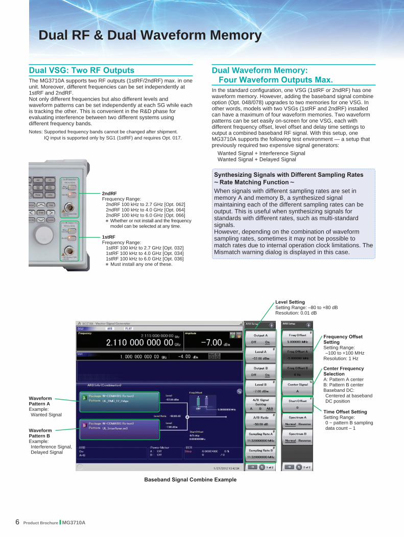
SSB Phase Noise<–140 dBc/Hz (nom.) @100 MHz, 20-kHz offset, CW<–131 dBc/Hz (typ.) @1 GHz, 20-kHz offset, CW <–125 dBc/Hz (typ.) @2 GHz, 20-kHz offset, CW
SSB phase noise is an important performance index for signal generators. For example, when using a signal generator for the following purposes, it is important to pre-confirm that the signal generator performance satisfies the measurement specifications. • Communications with narrow bandwidth of several kHz• OFDM Signals with narrow subcarrier gap• CW interference waveforms
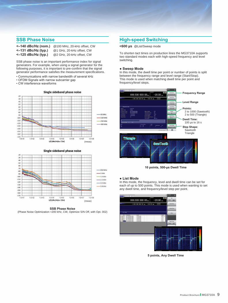
● Sweep ModeIn this mode, the dwell time per point or number of points is split between the frequency range and level range (Start/Stop). This mode is used when matching dwell time per point and frequency/level steps.
● List ModeIn this mode, the frequency, level and dwell time can be set for each of up to 500 points. This mode is used when wanting to set any dwell time, and frequency/level step per point.
High-speed Switching<600 µs @List/Sweep mode
To shorten tact times on production lines the MG3710A supports two standard modes each with high-speed frequency and level switching.
10 points, 500-µs Dwell Time
5 points, Any Dwell Time
SawTooth
Triangle
Frequency Range
Level Range
Points: 2 to 1000 (Sawtooth)2 to 500 (Triangle)
Dwell Time: 100 µs to 16 s
Step Shape:SawtoothTriangle
SSB Phase Noise(Phase Noise Optimization <200 kHz, CW, Optimize S/N Off, with Opt. 002)
(meas)
(meas)
10 Product Brochure l MG3710A
Supports Rubidium Reference Oscillator (Option)Three reference oscillator options are supported. Select the high-stability reference oscillator option [Opt. 002] when requiring high accuracy depending on the measurement conditions; for even higher accuracy, select the rubidium reference oscillator [Opt. 001].However, if external high-accuracy reference signals are available, selecting the standard reference oscillator option helps reduce unnecessary costs.
● Reference Oscillator• StandardAging Rate: ±1 × 10⁻⁶/year, ±1 × 10⁻⁷/dayTemperature Stability: ±2.5 × 10⁻⁶ (5° to 45°C)
• High Stability Reference Oscillator [Opt. 002]Aging Rate: ±1 × 10⁻⁷/year, ±1 × 10⁻⁸/dayTemperature Stability: ±2 × 10⁻⁸ (5° to 45°C)Start-up Characteristics∗: ±5 × 10⁻⁷ (2 minutes after power-on)
±5 × 10⁻⁸ (5 minutes after power-on)
● Rubidium Reference Oscillator [Opt. 001]Aging Rate: ±1 × 10⁻¹⁰/monthTemperature Stability: ±2 × 10⁻⁹ (5° to 45°C)Start-up Characteristics∗: ±1 × 10⁻⁹ (7.5 minutes after power-on)
∗: Compared to frequency after 24-h warm-up at 23°C
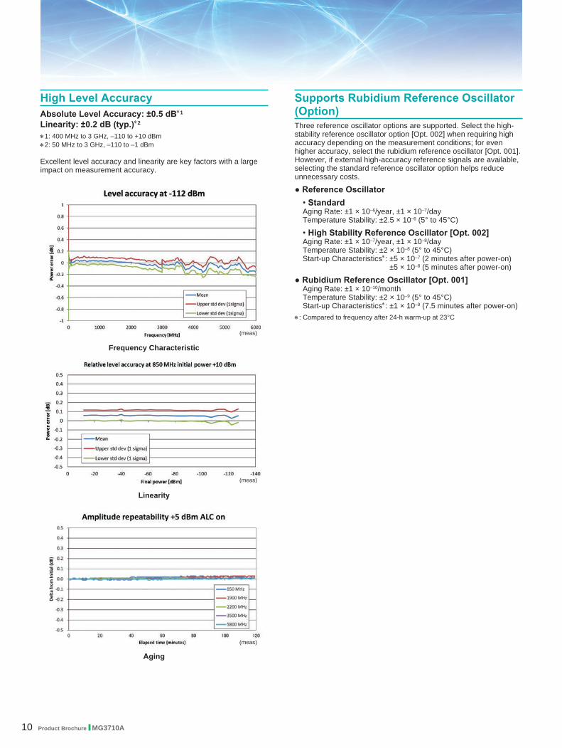
High Level AccuracyAbsolute Level Accuracy: ±0.5 dB∗1
Linearity: ±0.2 dB (typ.)∗2
∗1: 400 MHz to 3 GHz, –110 to +10 dBm∗2: 50 MHz to 3 GHz, –110 to –1 dBm
Excellent level accuracy and linearity are key factors with a large impact on measurement accuracy.
Frequency Characteristic
Linearity
Aging
(meas)
(meas)
(meas)

Product Brochure l MG3710A 11
Wide Vector Modulation Bandwidth160 MHz∗/120 MHz (using Internal baseband signal generator)160 MHz (using External IQ input)Using the standard internal baseband signal generator offers a wide vector modulation bandwidth of 160 MHz. ∗: Supports firmware version 2.00.00 and later. Can generate 160-MHz bandwidth
signals (Wireless LAN IEEE802.11ac) only when using MX370111A WLAN IQproducer and MX370111A-002 802.11ac (160 MHz) option. The latest version can be downloaded from the Anritsu homepage. <https://www1.anritsu.co.jp/Download/MService/Login.asp>
Large-capacity Waveform Memory64 Msamples (256 MB) [with 1stRF, 2ndRF]256 Msamples (1 GB) [Opt. 045∗1/075∗2]1024 Msamples (4 GB) [Opt. 046∗1/076∗2] ∗1: ARB Memory Upgrade 256 Msample for 1stRF [Opt. 045]
ARB Memory Upgrade 1024 Msample for 1stRF [Opt. 046]∗2: ARB Memory Upgrade 256 Msample for 2ndRF [Opt. 075]
ARB Memory Upgrade 1024 Msample for 2ndRF [Opt. 076]
Memory size is the most important specification for arbitrary waveform memory. If the memory is small, large waveform patterns cannot be handled and the number of cases when multiple waveform patterns cannot be loaded increases. When this happens, the time to reload another waveform pattern wastes evaluation time and lowers efficiency. The MG3710A has a large 64 Msamples memory as standard and this can be upgraded to either 4 times (256 Msamples) or 16 times (1024 Msamples) by adding these options.
High All-purpose Baseband Performance
Point:Adding the baseband signal combine function (Opt. 048/078) supports waveform memories which can either be used separately or linked to multiply the memory size. ∗: When attempting to load a waveform pattern exceeding the size of one
memory, the memories are linked automatically to load the large pattern. However, in this case, other waveform patterns cannot be loaded into any remaining free space. When dealing with many waveform patterns, we recommend upgrading the ARB memory size. If the waveform pattern can be handled by one memory, other waveform patterns can be loaded into the remaining free space and the other memory. The maximum size per waveform pattern supported by the MG3710A varies with the IQproducer version.
Free Waveform GenerationASCII-format IQ sample data files created by other general-purpose EDA tools, such as MATLAB, can be converted into MG3710A waveform pattern files. Support for customer waveform pattern file creation makes the MG3710A ideal for R&D simulation applications too.
Point:One unit supports WLAN IEEE802.11ac signal generation and output !• Upper Frequency Limit: 6 GHz• RF Modulation Bandwidth: 160 MHz• Dual RF: Two RF Outputs• Waveform Generation Software• WLAN IQproducer (MX370111A & MX370111A-002)The MG3710A supports output from 160-MHz bandwidth signals to non-contiguous 80 MHz + 80 MHz signals in one unit, which generally requires two signal generators.
Example: Support IEEE802.11ac signal generation and output
11ac Bandwidth 20/40/80/160 MHz 80 MHz + 80 MHz (non-contiguous)
MG3710A∗1 ∗2
∗1: MX370111A WLAN IQproducer and MX370111A-002 802.11ac (160 MHz) option installed. For detail, refer to the IQproducer catalog.
∗2: 2ndRF option MG3710A-062 (2.7 GHz)/064 (4 GHz)/066 (6 GHz) installed.
Maximum Waveform Pattern Size and Required Options for Simultaneous Use1stRF (Opt. 032/034/036)
Combination of Baseband Signal
(Opt. 048)
ARB Memory Upgrade 256 Msample (Opt. 045)ARB Memory Upgrade 1024 Msample (Opt. 046)
W/O With Opt. 045 With Opt. 046
W/O 64 Msamples × 1 pc
256 Msamples × 1 pc
1024 Msamples × 1 pc∗1
With Opt. 048∗2
64 Msamples × 2 pcs
128 Msamples × 1 pc
256 Msamples × 2 pcs
512 Msamples × 1 pc
1024 Msamples × 2 pcs∗1
2ndRF (Opt. 062/064/066)Combination of
Baseband Signal (Opt. 078)
ARB Memory Upgrade 256 Msample (Opt. 075)ARB Memory Upgrade 1024 Msample (Opt. 076)
W/O With Opt. 075 With Opt. 076
W/O 64 Msamples × 1 pc
256 Msamples × 1 pc
1024 Msamples × 1 pc∗1
With Opt. 078∗2
64 Msamples × 2 pcs
128 Msamples × 1 pc
256 Msamples × 2 pcs
512 Msamples × 1 pc
1024 Msamples × 2 pcs∗1
∗1: The maximum size per waveform pattern supported by the MG3710A varies with the IQproducer version.
∗2: The Baseband Signal Combine option supports two ARB memories and can either set two different waveform patterns or combine them as one memory to support one large waveform pattern.
12 Product Brochure l MG3710A
Expandability
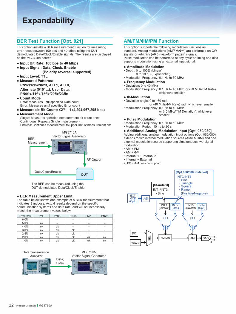
BER Test Function [Opt. 021]This option installs a BER measurement function for measuring error rates between 100 bps and 40 Mbps using the DUT demodulated Data/Clock/Enable signals. The results are displayed on the MG3710A screen.
● Input Bit Rate: 100 bps to 40 Mbps● Input Signal: Data, Clock, Enable
(Polarity reversal supported)● Input Level: TTL● Measured Patterns:
PN9/11/15/20/23, ALL1, ALL0, Alternate (0101...), User Data, PN9fix/11fix/15fix/20fix/23fix
● Count ModeData: Measures until specified Data countError: Measures until specified Error count
● Measurable Bit Count: ≤232 – 1 (4,294,967,295 bits)● Measurement Mode
Single: Measures specified measurement bit count onceContinuous: Repeats Single measurementEndless: Continues measurement to upper limit of measurement bits
AM/FM/ΦM/PM FunctionThis option supports the following modulation functions as standard. Analog modulations (AM/FM/ΦM) are performed on CW signals or arbitrary (ARB) waveform pattern signals. Pulse modulation can be performed at any cycle or timing and also supports modulation using an external input signal.
● Amplitude Modulation• Depth: 0 to 100% (Linear)
0 to 10 dB (Exponential)• Modulation Frequency: 0.1 Hz to 50 MHz● Frequency Modulation• Deviation: 0 to 40 MHz• Modulation Frequency: 0.1 Hz to 40 MHz, or (50 MHz-FM Rate),
whichever smaller● Φ-Modulation• Deviation angle: 0 to 160 rad.
or (40 MHz/ΦM Rate) rad., whichever smaller• Modulation Frequency: 0.1 Hz to 40 MHz,
or (40 MHz/ΦM Deviation), whichever smaller
● Pulse Modulation• Modulation Frequency: 0.1 Hz to 10 MHz• Modulation Period: 10 ns to 20 s● Additional Analog Modulation Input [Opt. 050/080]Adding additional analog modulation input options (Opt. 050/080) extends to two internal modulation sources (AM/FM/ΦM) and one external modulation source supporting simultaneous two-signal modulation.• AM + FM• AM + ΦM• Internal 1 + Internal 2• Internal + External ∗: FM + ΦM does not support.
● BER Measurement Upper LimitThe table below shows one example of a BER measurement that indicates SyncLoss. Actual results depend on the specific communication systems and data rate, and will not necessarily match the measurement values below.
Error Rate PN9 PN11 PN15 PN20 PN236.0% – – – – –5.0% ok – – – –4.0% ok ok – – –3.0% ok ok ok – –2.5% ok ok ok – –2.0% ok ok ok ok ok1.0% ok ok ok ok ok

Product Brochure l MG3710A 13
AWGN Signal Addition Screen
Power Meter Measurement Screen
Checking Com Port: 1. Display Windows
Press [Shift] + [Context (Windows)] or Right-click mouse > Show Desktop
2. Display Device Manager Start > My Computer > Properties > Hardware > Device Manager
3. Check Ports (COM & LPT)
USB Power Sensors [Sold separately]Up to two USB power sensors can be connected to the MG3710A to display the measurement results on the MG3710A screen.
● USB Power SensorModel Frequency Range Dynamic Range
MA24104A∗ 600 MHz to 4 GHz +3 to +51.76 dBmMA24105A 350 MHz to 4 GHz +3 to +51.76 dBmMA24106A 50 MHz to 6 GHz –40 to +23 dBmMA24108A 10 MHz to 8 GHz –40 to +20 dBmMA24118A 10 MHz to 18 GHz –40 to +20 dBmMA24126A 10 MHz to 26 GHz –40 to +20 dBm
∗: MA24104A has been discontinued. Replacement model is MA24105A.
Level Offset: –100 to +100 dB Average: 1 to 2048 Unit: dBm, W COM Port: 2 to 8
Local Signal I/O for MIMO Signal Source [Opt. 017]The Sync Multi SG function shares local, baseband and trigger signals between multiple MG3710A units to output phase coherency signals synchronized with the signal output timing. An 8×8 MIMO test system is configured easily from four MG3710A units composed of one master and three slaves.
Synchronization mode: Master, Slave, SG1 & 2Number of Slaves: 1 to 3Slave Position: 1 to 3Local Synchronization: On/OffIQ Phase Adjustment: –360 deg. to +360 deg.,
Resolution 0.01 deg.IQ Delay: –400 ns to +400 ns, Resolution 1 ps
AWGN Generator [Opt. 049∗1/079∗2]∗1: AWGN for 1stRF [Opt. 049]∗2: AWGN for 2ndRF [Opt. 079]
This option adds internally generated AWGN to the wanted signal. The AWGN output is switched on and off just by pressing the On/Off button.● Absolute C/N Ratio: ≤40 dB

14 Product Brochure l MG3710A
Level Setting
Frequency Setting
Modulation Screen (Mode)
Waveform Pattern Selection Power Meter Function BER Function
Operability
Easy Touch-panel OperationSimply touching parts of the screen display with a finger fetches related function keys and numeric inputs, offering a fast and easy way of navigating through multilayer menus.

Product Brochure l MG3710A 15
Two Signal FlowchartsPressing the on-screen button toggles instantly between the Hardware Block Chart and the ARB Info screens. The Hardware Block Chart is a quick-and-easy way to grasp the status of each block (ARB, AWGN, I/Q, Analog Mod, Pulse Mod, Local) at a glance. The ARB Info screen displays more details about the ARB/AWGN block showing the baseband signal combine status of memory A + memory B, memory A + AWGN, etc.
Frequency Channel TableSometimes frequencies need setting by Channel No. The built-in frequency channel table where frequencies are set by channel number is ideal for this application. Once set and saved, these pre-settings can be read whenever needed.
Channel Table Setting• Group: 1 to 19• Start Channel: 0 to 20000• End Channel: (Start Channel) to 20000• Start Frequency• Channel Spacing
Channel Table Setting Screen
Hardware Block Chart (Explanation)
Hardware Block Chart Screen
ARB Info Screen
1
2
7
12
3 4
5
106
11
8
13
9
14
Hardware Block Chart Display Contents (Explanation)
No. Display Example Display Description
1
ARB ARB block
On/OffIndicates On/Off of ARB (function to generate modulated signals with arbitrary waveform patterns)
Out Indicates On/Off of the arbitrary waveform pattern output
2 AWGN AWGN blockOn/Off Indicates On/Off of AWGN addition
3Analog Mod Analog Modulation block
AM/FM/ΦM Indicates the analog modulation (AM/FM/ΦM) during modulation
4
I/Q I/Q blockSrc: Internal/Analog I/Q In
Indicates the I/Q signal source
Out: RF/Analog I/Q Out
Indicates the output destination for baseband signals
5
Local Oscillator Local Oscillator blockSrc: Int/Ext/Sync Indicates the Local signal source
Out: –/On/Off Indicates On/Off of the Local signal external output
6 Pulse Mod Pulse Modulation blockOn/Off Indicates On/Off of Pulse modulation
7 –Indicates that inputs from two function blocks of the left side and bottom side are combined and output to the function block of the right side
8 –Indicates that the input Local signal from the bottom side is modulated with the input signal from the left side and output to the function block of the right side
9 – Indicates the RF Output is On
10 Analog I/Q Out Indicates the Analog I/Q signal is set to the external output
11 Analog I/Q In Indicates the Analog I/Q signal is set to theexternal input
12
LO In(For SG1)
Indicates the SG1 Local signal source is setto Ext (input from the rear LO Input connector)
SG1 (For SG2)
Indicates the SG2 Local signal source is setto Sync and the signal is input from SG1
13
SG2 (For SG1)
Indicates the SG1 Local signal external output setting is On and the signal is output to SG2.If SG2 is not installed, “LO Out” (output from the rear LO Output connector) is displayed
LO Out (For SG2)
Indicates the Local signal external output setting (output from the rear LO Output connector) is On
14 – Click to switch Hardware Block Chart and ARB Info display

16 Product Brochure l MG3710A
Command Format Setting Example
Analog IQ I/O Setting Screen
Connection with External Equipment
Remote Control Interfaces The MG3710A has GPIB, Ethernet and USB interfaces as standard, supporting the following functions:• Control all functions, except power switch • Read all status conditions and settings• Interrupts and serial pollsWhile in the Local status, the interface is determined automatically by the communication start command from the external controller (PC). To change the interface, put the MG3710A into the Local status again by pressing the Local key on the front panel and then send a command via the desired interface.
● GPIB: Conforms to IEEE488.1/IEEE488.2 standardsSH1, AH1, T6, L4, SR1, RL1, PP0, DC1, DT0, C0, E2
● Ethernet: Conforms to VXI-11 protocol using TCP/IP Control programs
SH1, AH1, T6, L4, SR1, RL1, PP0, DC1, DT0, C0
● USB: Conforms to USBTMC-USB488 protocolsSH1, AH1, T6, L4, SR1, RL1, PP0, DC1, DT0, C0n
USB Connections The two type-A USB2.0 connectors on the front and rear panels support keyboard, mouse and USB memory connections. Supported USB power sensors can be connected too.
● USB Power Sensor [Sold separately] Frequency Range: 600 MHz to 4 GHz [MA24104A]∗
350 MHz to 4 GHz [MA24105A] 50 MHz to 6 GHz [MA24106A] 10 MHz to 8 GHz [MA24108A] 10 MHz to 18 GHz [MA24118A] 10 MHz to 26 GHz [MA24126A]
∗: MA24104A has been discontinued. Replacement model is MA24105A.
Analog IQ Input/Output [Opt. 018]This option adds analog IQ input and output connectors to the front and rear panels, respectively. It only supports SG1 (1stRF).Input: I Input, Q InputOutput: I Output, I Output, Q Output, Q Output,
To remotely control the MG3710A, either select the SCPI mode command format defined by the SCPI Consortium, or select backwards compatible modes supporting earlier MG3700A, MS269xA, and MS2830A commands
● Analog IQ Input AdjustmentSetting Range: –100 mV to +100 mV
● Analog IQ Output AdjustmentOutput Voltage: 0.0 to 120.0%In-phase DC offset: –2.5 V to +5.0 VDifferential DC offset: –50 mV to +50 mV

Product Brochure l MG3710A 17
SG2 Marker Setup ScreenMemory A (1A/2A/3A), Memory B (1B/2B/3B)
The defaults are as follows:
Marker Signal ConnectorSG1/Memory A/Marker 1 Marker 1 OutputSG1/Memory A/Marker 2 Marker 2 (@AUX)SG1/Memory A/Marker 3 Marker 3 (@AUX)
Trigger Input Start and Frame triggers are installed as standard for outputting waveform patterns synchronized with externally input trigger signals.
● Start Trigger OperationAt Start Trigger operation, after the waveform pattern is selected, output is started and continued by the rise timing of the first external trigger signal. Second and subsequent input external trigger signals are disabled. This is used when receiving a Start Trigger signal and reference frequency signal from the DUT at the MG3710A.
● Frame Trigger OperationAt Frame Trigger operation, one frame of the waveform pattern is output at the rise timing of the external trigger signal. When frame output is finished, the trigger wait state is returned. This is used when receiving a Frame Trigger signal from the DUT at the MG3710A.Frame Trigger supports three operations as follows:
(1) No RetriggerIgnores triggers received during pattern output (default setting)
Marker Output Editing Marker 1 Output [Standard]Marker 2 & Marker 3 Output [Requires J1539A AUX Conversion Adapter]When the Marker Setup function Edit Mode is Off, a marker signal combining the preset waveform pattern with marker information is output. When the Edit Mode is On, any marker for output can be set at the MG3710A screen. Up to 12 markers can be set for SG1/SG2, memory A/B and Marker 1 to 3.
(2) Buffered TrigHolds triggers received during pattern output until current pattern output completed and then outputs next frame
(3) Restart on TrigImmediately restarts pattern when trigger received during pattern output
There are three output connectors: Marker 1 Output on the rear panel and the AUX connector (Marker 2 Output and Marker 3 Output). The connector output signal layout can be selected freely.

18 Product Brochure l MG3710A
IQproducer Main ScreenSystem (Cellular)
IQproducer Main ScreenSystem (Non-Cellular)
MX370108A LTE IQproducer/MX370108A-001 LTE-Advanced FDD OptionLTE-Advanced Easy Setup Screen
IQproducer OptionsMX370101A HSDPA/HSUPA IQproducerMX370102A TDMA IQproducerMX370103A CDMA2000 1xEV-DO IQproducerMX370104A Multi-carrier IQproducerMX370105A Mobile WiMAX IQproducerMX370106A DVB-T/H IQproducerMX370107A Fading IQproducerMX370108A LTE IQproducerMX370108A-001∗1 LTE-Advanced FDD OptionMX370109A XG-PHS IQproducerMX370110A LTE TDD IQproducerMX370110A-001∗2 LTE-Advanced TDD OptionMX370111A WLAN IQproducerMX370111A-002∗3 802.11ac (160 MHz) OptionMX370112A TD-SCDMA IQproducer
∗1: Requires MX370108A∗2: Requires MX370110A∗3: Requires MX370111A. Only for MG3710A
IQproducer Waveform Generation Software
Waveform Generation Software (Separate license)The IQproducer system provides an easy-to-use GUI for setting parameters according to each communications method. The parameter setting results file can be saved as a file for easy recall later. ∗ For detail, refer to the IQproducer catalog.
If a license is not installed in the MG3710A, characters are displayed in red. Without a license, the IQproducer functions can still be tested but a license must be installed to actually output created waveform patterns.
MX370111A WLAN IQproducer/MX370111A-002 802.11ac (160 MHz) OptionWLAN IEEE802.11ac Easy Setup Screen
The following table shows the maximum size for each waveform pattern generated using IQproducer.The maximum usable size (load) depends on the ARB memory expansion option installed in the main frame.
IQproducer Model/Name MG3710A MG3700A MS269xA MS2830A MG3740A∗∗∗∗01A HSDPA/HSUPA
512 Msamples
512 Msamples
256 Msamples 256 Msamples –∗∗∗∗02A TDMA 512 Msamples∗∗∗∗03A CDMA2000 1xEV-DO – – –∗∗∗∗04A Multi-carrier 1024 Msamples 256 Msamples 256 Msamples –∗∗∗∗05A Mobile WiMAX 512 Msamples –∗∗∗∗06A DVB-T/H – – –∗∗∗∗07A Fading 1024 Msamples – – 512 Msamples∗∗∗∗08A LTE
512 Msamples 256 Msamples
256 Msamples –∗∗∗∗09A XG-PHS – –∗∗∗∗10A LTE TDD
256 Msamples–
∗∗∗∗11A WLAN –∗∗∗∗12A TD-SCDMA –
∗∗∗∗: MX3701 or MX2699

Product Brochure l MG3710A 19
IQproducer Main ScreenGeneral Purpose
IQproducer Main ScreenSimulation & Utility
Convert Screen
Operating EnvironmentPC
OS Windows 2000 Professional∗1, Windows XP, Windows Vista∗2, Windows 7 Enterprise (32-bit)∗2, Windows 7 Professional (32-bit/64-bit)∗2
CPU Pentium III 1 GHz equivalent or fasterMemory 512 MB or more
Hard Disk 5 GB or more free space on the drive where this software is to be installed.
Peripheral Device
Display Displays with a resolution of 1024 × 768 pixels are best viewed using a small font setting
∗1: Does not support IQproducer Version 13.00 and later∗2: Supports IQproducer Version 12.00 and later
IQ Data Waveform PatternConvert
Digitized Data
Waveform PatternConvert
MG3700Aetc.
MG3710AConvert
IQproducerIQproducer supports the following functions free-of-charge as secondary waveform pattern creation functions.
● Convert● AWGN● Clipping● CCDF/FFT/Time Domain● Transfer & Setting/Transfer & Setting Wizard
Combination File Edit
Convert: Data Format Conversion(1) ASCII-format IQ data created with other software, such as
simulation software, can be converted to waveform pattern files used by the MG3710A.
(2) Data files captured with Anritsu MS269xA Signal Analyzers and the capture function of the MS2830A Signal Analyzer can be converted to waveform pattern files used by the MG3710A.
(3) Waveform patterns created by other Anritsu vector signal generators (MG3700A, MS269xA-020, MS2830A-020/021) can be converted to waveform pattern files used by the MG3710A and vice versa.

20 Product Brochure l MG3710A
Clipping Screen
CCDF Screen
AWGN ScreenFFT Screen
Time Domain Screen
ClippingThis function clips each type of waveform pattern. The clipped waveform pattern is created by setting the filter, bandwidth, and repetition times.
AWGN Waveform GenerationThis function establishes the sampling rate and bandwidth, allowing any AWGN waveform pattern to be created. In addition, when the first combined waveform pattern (Wanted Signal) is selected, the Wanted Signal bandwidth and sampling rate are set automatically. The resulting AWGN waveform pattern can be combined with an existing waveform pattern, which is useful for base-station dynamic-range measurements.
● FFT (Fast Fourier Transform)Up to 4 created waveform patterns are read, FFT-processed and displayed simultaneously as FFT graphs.
● Time DomainUp to 4 created waveform patterns are read, and displayed simultaneously as Time Domain graphs.
Main setting parameters(1) Wanted Signal Bandwidth:
Setting range: 0.0010 MHz to 120.0000 MHz(2) AWGN BW (B)/Wanted Signal BW (A):
Magnification of AWGN to Wanted SignalSetting range: 1.0, 1.5, 2.0, 2.5
(3) Sampling Rate:Setting range: 0.0200 MHz to 160.0000 MHzNote: Same value as wanted signal
(4) AWGN Bandwidth (B):Calculated automatically from (1) and (2) under following items:Limit range:
0.001 MHz to 20.000 MHz: Sampling rate/2 max.20.001 MHz to 120.000 MHz: Sampling rate max.
CCDF/FFT/Time Domain Graphical Displays● CCDF (Complementary Cumulative Distribution Function)Up to 8 created waveform patterns are read and displayed simultaneously as CCDF graphs.

Product Brochure l MG3710A 21
Transfer & Setting Screen
Transfer & Setting ScreenCombination File Edit Selection
Combination File Edit Screen
Transfer and Settings: Data TransferWaveform pattern files, graphics files, firmware version upgrades, etc., can be moved between a LAN-connected PC and MG3710A. When several MG3710A units are connected via LAN, waveform patterns can be transferred by a single operation, helping cut work times. Moreover, waveform pattern files saved on the hard disk of a remote- controlled MG3710A can be opened in arbitrary waveform memory to select and output the waveform pattern.
Combination files can also be used to create waveform sequences. Receive signal status transitions can be verified by using Sequence Mode Combination files defining switching and repetition times for multiple waveform patterns.Required waveform patterns and combination are saved to memory. Moreover, external triggers can be used to repeat each waveform pattern any number of times.⇒ Efficient memory use⇒ Validate response status transitions⇒ Manual control of sequences
● Combination File Edit FunctionThe Combination File Edit function is a Transfer & Setting Edit function. The following parameters are set automatically by selecting the Combination File:
• Waveform pattern• Repetition times• Interference waveform pattern (memory B)• Frequency offset used when memory A and B added• Level ratio (This value represents CN when memory A and B
are added, or the relative level between elements when using only memory A.)
Using Combination Files that place the wanted and interference waveforms in separate memories makes it easy to measure receiver characteristics.
22 Product Brochure l MG3710A
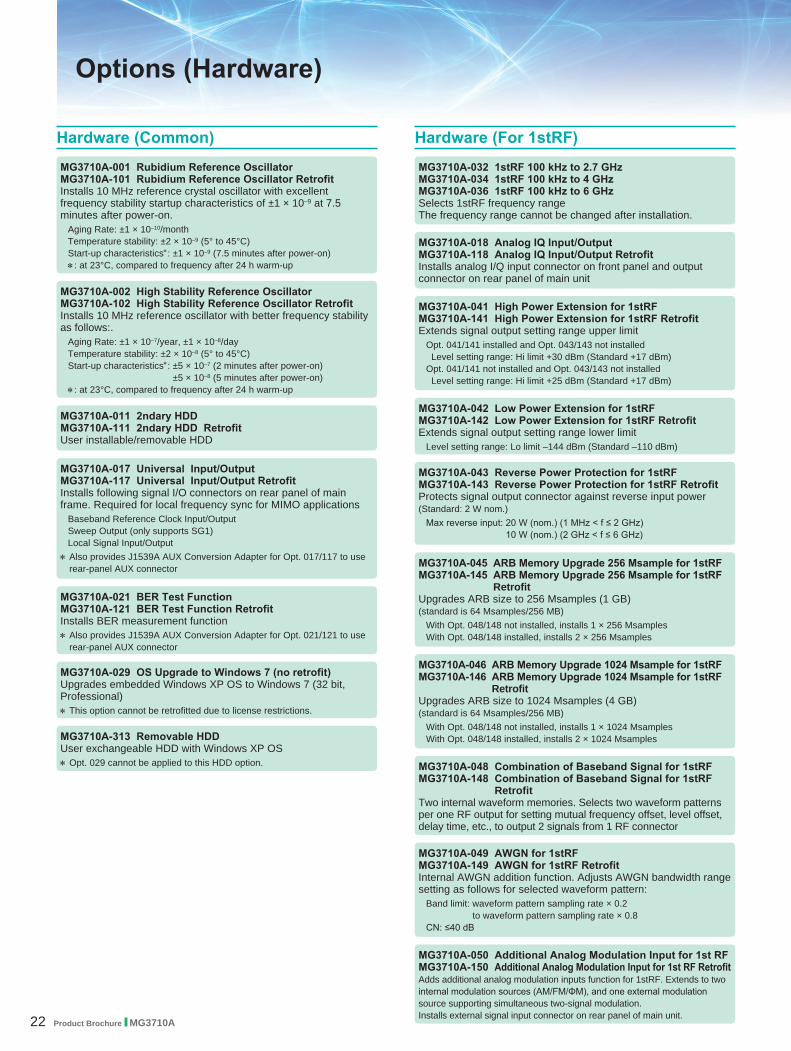
MG3710A-313 Removable HDDUser exchangeable HDD with Windows XP OS∗ Opt. 029 cannot be applied to this HDD option. MG3710A-048 Combination of Baseband Signal for 1stRF
MG3710A-148 Combination of Baseband Signal for 1stRF Retrofit
Two internal waveform memories. Selects two waveform patterns per one RF output for setting mutual frequency offset, level offset, delay time, etc., to output 2 signals from 1 RF connector
MG3710A-046 ARB Memory Upgrade 1024 Msample for 1stRFMG3710A-146 ARB Memory Upgrade 1024 Msample for 1stRF
RetrofitUpgrades ARB size to 1024 Msamples (4 GB) (standard is 64 Msamples/256 MB)
With Opt. 048/148 not installed, installs 1 × 1024 Msamples With Opt. 048/148 installed, installs 2 × 1024 Msamples
MG3710A-049 AWGN for 1stRFMG3710A-149 AWGN for 1stRF RetrofitInternal AWGN addition function. Adjusts AWGN bandwidth range setting as follows for selected waveform pattern:
Band limit: waveform pattern sampling rate × 0.2 to waveform pattern sampling rate × 0.8
CN: ≤40 dB
MG3710A-045 ARB Memory Upgrade 256 Msample for 1stRFMG3710A-145 ARB Memory Upgrade 256 Msample for 1stRF
RetrofitUpgrades ARB size to 256 Msamples (1 GB) (standard is 64 Msamples/256 MB)
With Opt. 048/148 not installed, installs 1 × 256 Msamples With Opt. 048/148 installed, installs 2 × 256 Msamples
MG3710A-043 Reverse Power Protection for 1stRFMG3710A-143 Reverse Power Protection for 1stRF RetrofitProtects signal output connector against reverse input power (Standard: 2 W nom.)
Max reverse input: 20 W (nom.) (1 MHz < f ≤ 2 GHz) 10 W (nom.) (2 GHz < f ≤ 6 GHz)
MG3710A-042 Low Power Extension for 1stRF MG3710A-142 Low Power Extension for 1stRF RetrofitExtends signal output setting range lower limit
Level setting range: Lo limit –144 dBm (Standard –110 dBm)
MG3710A-041 High Power Extension for 1stRFMG3710A-141 High Power Extension for 1stRF RetrofitExtends signal output setting range upper limit
Opt. 041/141 installed and Opt. 043/143 not installed Level setting range: Hi limit +30 dBm (Standard +17 dBm)Opt. 041/141 not installed and Opt. 043/143 not installed Level setting range: Hi limit +25 dBm (Standard +17 dBm)
MG3710A-018 Analog IQ Input/Output MG3710A-118 Analog IQ Input/Output RetrofitInstalls analog I/Q input connector on front panel and output connector on rear panel of main unit
MG3710A-032 1stRF 100 kHz to 2.7 GHzMG3710A-034 1stRF 100 kHz to 4 GHzMG3710A-036 1stRF 100 kHz to 6 GHzSelects 1stRF frequency rangeThe frequency range cannot be changed after installation.
MG3710A-029 OS Upgrade to Windows 7 (no retrofit)Upgrades embedded Windows XP OS to Windows 7 (32 bit, Professional)∗ This option cannot be retrofitted due to license restrictions.
MG3710A-021 BER Test Function MG3710A-121 BER Test Function RetrofitInstalls BER measurement function∗ Also provides J1539A AUX Conversion Adapter for Opt. 021/121 to use
rear-panel AUX connector
MG3710A-017 Universal Input/Output MG3710A-117 Universal Input/Output RetrofitInstalls following signal I/O connectors on rear panel of main frame. Required for local frequency sync for MIMO applications
Baseband Reference Clock Input/OutputSweep Output (only supports SG1)Local Signal Input/Output
∗ Also provides J1539A AUX Conversion Adapter for Opt. 017/117 to use rear-panel AUX connector
MG3710A-011 2ndary HDD MG3710A-111 2ndary HDD RetrofitUser installable/removable HDD
MG3710A-002 High Stability Reference Oscillator MG3710A-102 High Stability Reference Oscillator RetrofitInstalls 10 MHz reference oscillator with better frequency stability as follows:.
Aging Rate: ±1 × 10⁻⁷/year, ±1 × 10⁻⁸/dayTemperature stability: ±2 × 10⁻⁸ (5° to 45°C)Start-up characteristics∗: ±5 × 10⁻⁷ (2 minutes after power-on)
±5 × 10⁻⁸ (5 minutes after power-on)∗: at 23°C, compared to frequency after 24 h warm-up
MG3710A-001 Rubidium Reference OscillatorMG3710A-101 Rubidium Reference Oscillator RetrofitInstalls 10 MHz reference crystal oscillator with excellent frequency stability startup characteristics of ±1 × 10⁻⁹ at 7.5 minutes after power-on.
Aging Rate: ±1 × 10⁻¹⁰/monthTemperature stability: ±2 × 10⁻⁹ (5° to 45°C)Start-up characteristics∗: ±1 × 10⁻⁹ (7.5 minutes after power-on)∗: at 23°C, compared to frequency after 24 h warm-up
Hardware (Common) Hardware (For 1stRF)
Options (Hardware)
MG3710A-050 Additional Analog Modulation Input for 1st RFMG3710A-150 Additional Analog Modulation Input for 1st RF RetrofitAdds additional analog modulation inputs function for 1stRF. Extends to two internal modulation sources (AM/FM/ΦM), and one external modulation source supporting simultaneous two-signal modulation.Installs external signal input connector on rear panel of main unit.

Product Brochure l MG3710A 23
MG3710A-075 ARB Memory Upgrade 256 Msample for 2ndRFMG3710A-175 ARB Memory Upgrade 256 Msample for 2ndRF
RetrofitUpgrades ARB size to 256 Msamples (1 GB) (standard is 64 Msamples/256 MB)
With Opt. 078/178 not installed, installs 1 × 256 Msamples With Opt. 078/178 installed, installs 2 × 256 Msamples
MG3710A-073 Reverse Power Protection for 2ndRFMG3710A-173 Reverse Power Protection for 2ndRF RetrofitProtects signal output connector against reverse input power (Standard: 2 W nom.)
Max reverse input: 20 W (nom.) (1 MHz < f ≤ 2 GHz), 10 W (nom.) (2 GHz < f ≤ 6 GHz)
MG3710A-072 Low Power Extension for 2ndRFMG3710A-172 Low Power Extension for 2ndRF RetrofitExtends signal output setting range lower limit
Level setting range: Lo limit –144 dBm (Standard –110 dBm)
MG3710A-071 High Power Extension for 2ndRFMG3710A-171 High Power Extension for 2ndRF RetrofitExtends signal output setting range upper limit
Opt. 071/171 installed and Opt. 073/173 not installed Level setting range: Hi limit +30 dBm (Standard +17 dBm)Opt. 071/171 not installed and Opt. 073/173 not installed Level setting range: Hi limit +25 dBm (Standard +17 dBm)
MG3710A-079 AWGN for 2ndRFMG3710A-179 AWGN for 2ndRF RetrofitInternal AWGN addition function. Adjusts AWGN bandwidth range setting as follows for selected waveform pattern:
Band limit: waveform pattern sampling rate × 0.2 to waveform pattern sampling rate × 0.8
CN: ≤40 dB
MG3710A-078 Combination of Baseband Signal for 2ndRFMG3710A-178 Combination of Baseband Signal for 2ndRF
RetrofitTwo internal waveform memories. Selects two waveform patterns per one RF output for setting mutual frequency offset, level offset, delay time, etc., to output 2 signals from 1 RF connector
MG3710A-076 ARB Memory Upgrade 1024 Msample for 2ndRFMG3710A-176 ARB Memory Upgrade 1024 Msample for 2ndRF
RetrofitUpgrades ARB size to 1024 Msamples (4 GB) (standard is 64 Msamples/256 MB)
With Opt. 078/178 not installed, installs 1 × 1024 Msamples With Opt. 078/178 installed, installs 2 × 1024 Msamples
MG3710A-062 2ndRF 100 kHz to 2.7 GHzMG3710A-064 2ndRF 100 kHz to 4 GHzMG3710A-066 2ndRF 100 kHz to 6 GHzMG3710A-162 2ndRF 100 kHz to 2.7 GHz RetrofitMG3710A-164 2ndRF 100 kHz to 4 GHz RetrofitMG3710A-166 2ndRF 100 kHz to 6 GHz RetrofitSelects 2ndRF frequency rangeThe frequency range cannot be changed after installation. Can only be retrofitted when 2ndRF not installed.
Hardware (For 2ndRF)
MG3710A-080 Additional Analog Modulation Input for 2nd RFMG3710A-180 Additional Analog Modulation Input for 2nd
RF RetrofitAdds additional analog modulation inputs function for 2ndRF. Extends to two internal modulation sources (AM/FM/ΦM), and one external modulation source supporting simultaneous two-signal modulation.Installs external signal input connector on rear panel of main unit.

24 Product Brochure l MG3710A
Waveform Patterns & License IQproducer LicenseIQproducer is PC application software for generating waveform patterns. The parameters are set using IQproducer and the waveform pattern is created to output the signal by selection at the MG3710A. This one software application includes all the following systems.Since it runs on any PC, the supported functions and parameter range can be verified before purchase. When outputting a waveform pattern from the MG3710A, no signal is output unless a license for that system is installed in the main frame.∗ Read the “IQproducer catalog” for details.
Model: MX370075AName: DFS (ETSI) Waveform PatternSets pulse signals for testing 5-GHz band WLAN DFS functions. The MX370075A supports the waveform patterns for the ETSI specifications. Pulse signals are output simply by selecting the pattern.
Model: MX370084AName: ISDB-Tmm Waveform PatternArchive of ARIB STD-B46 waveform patterns. Supports MER and spectrum evaluation of Tx characteristics tests and sensitivity/simple BER tests at Rx characteristics tests.
Model: MX370073AName: DFS Radar PatternSets pulse signals for testing 5-GHz band WLAN DFS functions. The MX370073A supports the waveform patterns for the TELEC and FCC test specifications. Pulse signals are output simply by selecting the pattern.
Model: MX370105AName: Mobile WiMAX IQproducerSets parameters according to IEEE 802.16e-2005, IEEE P802.16Rev2/D3 WirelessMAN-OFDMA MAC, PHY specifications and generates waveform patterns. Supports WirelessMAN-OFDMA specification used by 802.16e mobile standard.
Model: MX370106AName: DVB-T/H IQproducerSets parameters according to ETSI EN 300 744 V1.5.1 (2004-11) physical layer standard and generates DVB-T/H waveform patterns. Generated waveform patterns can be used for device TRx characteristics evaluation tests (Error Correction, BER graphics).
Model: MX370104AName: Multi-carrier IQproducerGenerates multi-carrier waveform patterns combination files using MG3710A Baseband Signal Combine function (requires Opt. 048/078).
Model: MX370103AName: CDMA2000 1xEV-DO IQproducerSets parameters according to CDMA2000 1xEV-DO Forward/Reverse specifications and generates 1xEV-DO waveform patterns.
Model: MX370102AName: TDMA IQproducerSets required parameters for TDMA waveform patterns and generates various waveform patterns. Setting parameters include Modulation, Frame, Slot, Data, Filter, etc. Supports wide application range including public wireless.
Model: MX370101AName: HSDPA/HSUPA IQproducerSets parameters according to HSDPA/HSUPA (Uplink and Downlink) specifications, and generates HSDPA/HSUPA waveform patterns including Fixed Reference Channel (3GPP TS 25.101 Annex A.7).
What is DFS?5-GHz band wireless LAN devices like meteorological radar, marine radar, etc., have a Dynamic Frequency Selection (DFS) function for switching to an empty channel when detecting a radio wave. At testing, pulse, chirping and hopping signals like those used by radar are output from the SG to the WLAN equipment to check that it does not output signals in that channel.
Options (Software)

Product Brochure l MG3710A 25
Model: MX370110AName: LTE TDD IQproducerGenerates wanted waveform patterns with parameters modified according to 3GPP TS 36.211, TS 36.212, TS 36.213 LTE TDD specifications.
Model: MX370111AName: WLAN IQproducerGenerates waveform patterns for IEEE Std 802.11-2007 and IEEE Std 802.11n-2009 IEEE 802.11a/b/g/j/n/p specifications.
Model: MX370111A-002Name: 802.11ac (160 MHz) OptionInstalling in the MX370111A supports waveform patterns generation compliant with IEEE802.11ac specifications.∗: Requires MX370111A. Only for MG3710A.
Model: MX370108A-001Name: LTE-Advanced FDD OptionInstalling in the MX370108A supports simple generation of carrier aggregation signals added by 3GPP Rel. 10. Additionally, clustered SC-FDMA signals can be generated at Uplink.∗: Requires MX370108A
Model: MX370110A-001Name: LTE-Advanced TDD OptionInstalling in the MX370110A supports simple generation of carrier aggregation signals added by 3GPP Rel. 10. Additionally, clustered SC-FDMA signals can be generated at Uplink.∗: Requires MX370110A
Model: MX370108AName: LTE IQproducerGenerates wanted waveform patterns with parameters modified according to 3GPP TS 36.211, TS 36.212, TS 36.213 LTE FDD specifications.
Model: MX370107AName: Fading IQproducerPerforms IQ channel fading processing, correlation matrix calculation, AWGN combination. Input data file created by selecting waveform pattern file created with other IQproducer software, and IQ data (ASCII) created with other general-purpose simulation tools.
Model: MX370109AName: XG-PHS IQproducerGenerates wanted waveform patterns with parameters modified according to Next Generation PHS Specification PHS (XGP: eXtended Global Platform) specifications. Model: MX370112A
Name: TD-SCDMA IQproducerGenerates wanted waveform patterns with parameters modified according to TD-SCDMA specifications standardized by TRx characteristics evaluation tests (excluding performance tests) for 3GPP TS 25.221, TS 25.222, TS 25.223, TS 25.105, TS 25.142
● Vector Signal Generator series Supported LTE-Advanced Carrier Aggregation Modes
Vector Signal Generator Series
Carrier AggregationMode
Vector Signal Generator Vector Signal Generator Option for Signal Analyzer
MG3710A∗1 MG3700A∗1 MS2690A seriesOpt. 020∗2
MS2830AOpt. 020/021∗2
Intra-band contiguous Carrier Aggregation, Intra-band non-contiguous Carrier Aggregation
(1 unit)
(1 unit)
(1 unit)
(1 unit)
Inter-band non-contiguous Carrier Aggregation
(2 RF 1 unit∗3, or 1 RF 2 units)
(2 units)
(2 units)
(2 units)
∗1: MX370108A LTE IQproducer and MX370108A-001 LTE-Advanced FDD Option installed. MX370110A LTE TDD IQproducer and MX370110A-001 LTE-Advanced TDD Option installed.
∗2: MX269908A LTE IQproducer and MX269908A-001 LTE-Advanced FDD Option installed. MX269910A LTE TDD IQproducer and MX269910A-001 LTE-Advanced TDD Option installed.
∗3: MG3710A-062 (2.7 GHz)/064 (4 GHz)/066 (6 GHz) 2ndRF Option installed.
● Vector Signal Generator seriesSupported WLAN IEEE802.11ac Signal Bandwidth
Vector Signal Generator Series
IEEE802.11acSignal Bandwidth
Vector Signal Generator Vector Signal Generator Option for Signal Analyzer
MG3710A∗1 MG3700A∗2 MS2690A seriesOpt. 020∗3
MS2830AOpt. 020/021∗3
20 MHz/40 MHz/80 MHz (1 unit)
(1 unit)
(1 unit)
(1 unit)
160 MHz (1 unit) — — —
80 MHz + 80 MHz (non-contiguous)
(2 RF 1 unit∗4, or 1 RF 2 units)
(2 units)
(2 units)
(2 units)
∗1: MX370111A WLAN IQproducer and MX370111A-002 802.11ac (160 MHz) Option installed.∗2: MX370111A WLAN IQproducer and MX370111A-001 802.11ac (80 MHz) Option installed.∗3: MX269911A WLAN IQproducer and MX269911A-001 802.11ac (80 MHz) Option installed.∗4: MG3710A-062 (2.7 GHz)/064 (4 GHz)/066 (6 GHz) 2ndRF Option installed.

26 Product Brochure l MG3710A
Pre-installed Waveform Patterns Cuts Costs
USB Power Sensor Efficient Equipment Investment
Large Measurement
Margin
Stable Measurements
Improves Yield
No External AmpStable Level Accuracy
Cuts Risk of Damage to DUT
Dual RF OutputsCuts Costs
Cuts Workload
● Supports –71 dBc∗ ACLR PerformanceHigh ACLR performance increases specification margin and improves stable measurement and yield.∗: W-CDMA, TestModel1, 64DPCH, 2 GHz
● Supports Maximum Two RF OutputsIn general, two signal generators are required to output CW × 2 waveforms with IM3 or modulation signals with different communication methods. Not only is the cost for two signal generators high, but two separate software licenses are required to output modulation signals. In addition, setting two separate signal generators doubles the work load.The MG3710A supports two signal generators (RF output) in one unit cutting equipment costs. And only one license is required to use modulation signals at two RF outputs. Moreover, the frequency and level synchronization function cuts work loads.
● High-power Output Option (Opt. 041/071) Supports CW Levels of +23 dBm
In general, an external amp is required when the output of a signal generator is insufficient, such as covering the measurement system transmission path loss and inputting high-level modulation signals for amp distortion characteristics tests. Since the output of an external amp cannot be assured, it must be checked with a power meter each time the frequency and level are changed. Moreover, when using an external amp, sometimes the DUT may be damaged by mishandling errors. The MG3710A high-power output supports signals required for measuring path loss. In addition, stable measurement is assured when used within the guaranteed setting range. And the risk of mistakenly damaging the DUT is reduced, even at the output limit.
License-free Pre-installed Waveform PatternsLTE FDD/TDD (E-TM1.1 to E-TM3.3), W-CDMA/HSPA, GSM, CDMA2000/1xEV-DO, WLAN 11a/b/g, Mobile WiMAX, etc.
Optional waveform generation tools are also available (license sold separately):
LTE FDD (MX370108A)LTE-Advanced FDD (MX370108A-001)LTE TDD (MX370110A)LTE-Advanced TDD (MX370110A-001)Mobile WiMAX (MX370105A)WLAN 11a/b/g/n/j/p (MX370111A)WLAN 11ac (MX370111A-002)TD-SCDMA (MX370112A) (etc.)
Up to two USB power sensors (separately sold) can be connected to the MG3710A. USB connectors to display the measurement results on the MG3710A screen.
USB Power Sensor Frequency Range: 600 MHz to 4 GHz [MA24104A]∗
350 MHz to 4 GHz [MA24105A] 50 MHz to 6 GHz [MA24106A] 10 MHz to 8 GHz [MA24108A] 10 MHz to 18 GHz [MA24118A] 10 MHz to 26 GHz [MA24126A]
∗: MA24104A has been discontinued. Replacement model is MA24105A.
Reference Signal Source for Tx Characteristics Tests of Amplifiers, etc.
Product Brochure l MG3710A 27
Dual RF outputs Cuts CostsOne RF Output Outputs Two
Signals: Wanted + Interference
Cuts Costs
Cuts Workload
BER Measurement Function
AWGN Generation Function
Efficient Equipment Investment
Multi-Standard Radio Rx Characteristics Tests
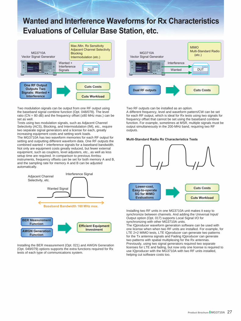
Wanted and Interference Waveforms for Rx Characteristics Evaluations of Cellular Base Station, etc.
Two modulation signals can be output from one RF output using the baseband signal combine function (Opt. 048/078). The level ratio (CN = 80 dB) and the frequency offset (±80 MHz max.) can be set as well. Tests using two modulation signals, such as Adjacent Channel Selectivity (ACS), Blocking, and Intermodulation (IM), etc., require two separate signal generators and a license for each, greatly increasing equipment costs and setting work loads.The MG3710A has two waveform memories for each RF output for setting and outputting different waveform data. One RF outputs the combined wanted + interference signals for a baseband bandwidth. Not only are equipment costs greatly reduced, but fewer external equipment, such as couplers, level adjusters, etc., as well as less setup time are required. In comparison to previous Anritsu instruments, frequency offsets can be set for both memory A and B, and the sampling rate for memory A and B can be adjusted automatically.
Installing the BER measurement (Opt. 021) and AWGN Generation (Opt. 049/079) options supports the extra functions required for Rx tests of each type of communications system.
Two RF outputs can be installed as an option.A different frequency, level and waveform pattern/CW can be set for each RF output, which is ideal for Rx tests using two signals for frequency offset that cannot be set using the baseband combine function. For example, sometimes at MSR, multiple signals must be output simultaneously in the 200-MHz band, requiring two RF outputs.
Lower-cost, Easy-to-operate
SG for MIMO Evaluations
Cuts Costs
Cuts Workload
Installing two RF units in one MG3710A unit makes it easy to synchronize between channels. And adding the Universal Input/Output option (Opt. 017) supports Local Signal I/O for synchronizing with other MG3710A units. The IQproducer waveform generation software can be used with one license when when two RF units are installed. For example, for LTE 2×2 MIMO tests, LTE IQproducer can generate two patterns for the Tx antenna signals and Fading IQproducer can generate two patterns with spatial multiplexing for the Rx antennas. Previously, using two signal generators required two separate licenses for LTE and fading, but now only one license is required to use IQproducer with the MG3710A with two RF units installed, helping cut software costs too.

28 Product Brochure l MG3710A
The MG3710A can save up to 1024 Msamples (4 GB) per RF. Memory size is one of the most important specifications for an arbitrary waveform signal generator. Small memory cannot save multiple waveform data and requires time-wasting reloading and measurement to output different signals each time.With large waveform memory
• Switch loaded waveform data instantaneously • Load multiple test waveforms ⇒ Reduce number of reloads ⇒ Cuts times
Two RF outputs can be installed as an option.Additionally, two RF output models with different frequencies can be installed. For example, if WLAN 11b/g are the wanted waveforms, mobile signals for LTE FDD, LTE TDD, W-CDMA, GSM, etc., are considered interference signals. Generally, these tests have high hardware and software costs because two separate signal generators are required. Using the MG3710A, the total investment costs for interference tests under simulated service conditions, such as WLAN + LTE FDD, or ISDB-T + W-CDMA, are reduced by selecting models with different frequencies for the 1stRF and 2ndRF outputs.
License-free Pre-installed Waveform PatternsWLAN 11a/b/g, Bluetooth, GPS, etc.
The following waveform patterns are available as options.ISDB-Tmm (MX370084A)
Optional waveform generation tools are also available (license separately sold):
DVB-T/H (MX370106A)Mobile WiMAX (MX370105A)WLAN 11a/b/g/n/j/p (MX370111A)WLAN 11ac (MX370111A-002)
Rx Sensitivity Tests for Multi-system Mobile Terminals, etc.
Dual RF outputs Cuts Costs
Pre-installed Waveform Patterns Cuts Costs
Large 4-GB Memory Max.
Reduces Reload Times
Cuts Test Times

Product Brochure l MG3710A 29
● Supports SSB Phase Noise Performance –140 dBc/Hz nom. (@100 MHz)
Phase noise performance affects measurement results at narrow bandwidths of several kHz. In particular, high phase-noise performance is required for interference waveforms.Improved SSB phase noise supports wider specification margins and stable measurements to improve yields.
<–140 dBc/Hz (nom.) @100 MHz, 20-kHz offset, CW <–131 dBc/Hz (typ.) @1 GHz, 20-kHz offset, CW <–125 dBc/Hz (typ.) @2 GHz, 20-kHz offset, CW
● TDMA IQproducer [MX370102A] Supports Following Modulation MethodsBPSK, DBPSK, PI/2DBPSK, QPSK, DQPSK, PI/4DQPSK, 8PSK, D8PSK, 16QAM, 32QAM, 256QAM, ASK, 2FSK, 4FSK,
The TDMA IQproducer PC software generates waveform patterns with any frame format or filter settings. One software package supports various narrowband digital communications.
Two modulation signals can be output from one RF output using the baseband signal combine function (Opt. 048/078). The level ratio (CN = 80 dB) and the frequency offset (±80 MHz max.) can be set as well. Usually, tests using two modulation signals, such as adjacent channel selectivity (ACS) and intermodulation characteristics (IM) require two signal generators as well as a software license for each signal generator.The MG3710A has two waveform memories for each RF output for setting and outputting different waveform data. One RF outputs the combined wanted + interference signals for a baseband bandwidth.Not only are equipment costs greatly reduced, but fewer external equipment, such as couplers, level adjusters, etc., as well as less setup time are required.
● Supports BER Measurement Function [Opt. 021]The BER can be measured using the DUT-demodulated Data/Clock/Enable. The measurement results are displayed on the MG3710A screen.
• Input Bit Rate: 100 bps to 40 Mbps
Rx Characteristics Evaluation Tests for Digital Narrowband Communications, Public Safety, etc.
Supports Various Modulation Methods Cuts Costs
BER Measurement Function
Efficient Equipment Investment
Large Measurement
Margin
Stable Measurements
Improves Yield
One RF Outputs Two Wanted + Interference
Signals
Cuts Costs
Cuts Workload

30 Product Brochure l MG3710A
Easy-to-use Panel
1 Power SwitchSwitches between standby status in which AC power is supplied, and operating power-on status. At standby the key lamp is orange; at power-on it is green. To supply power press the switch for 2 seconds or more.
2 HDD LampLit when internal hard disk being accessed.
3 Copy KeyCopies screen display to file.
4 Recall KeyDisplays menu for recalling parameter files.
5 Save KeyDisplays menu for saving parameter files.
6 Cal KeyDisplays menu for performing calibration.
7 Local Key/Remote LampLocal Key: Return remote control via GPIB, Ethernet,
USB (B) to local control and enables panel setting.
Remote Lamp: Lit while MG3710A under remote control. 8 Preset Key
Displays Preset menu to initialize parameter settings.9 Q Input Connector
Input for external Q phase signal. Requires Opt. 018 and only supports SG1 (1stRF); does not support SG2 (2ndRF).
10 I Input Connector Input for external I phase signal. Requires Opt. 018 and only supports SG1 (1stRF); does not support SG2 (2ndRF).
11 Function KeysSelect and execute functions displayed at right edge of display. Displayed functions menus are multi-level with page hierarchy.
12 SG1/SG2/IQpro KeysSG1: Switches setting target to SG1SG2: Switches setting target to SG2IQpro: Starts IQproducer on main frame. IQproducer
may not start running for a few seconds to minutes after pressing this key.
13 Main Function KeysDisplays menus for setting and executing main functions: [Frequency], [Level], [Sweep/List], [Mode],
[AM], [FM/ΦM], [Pulse], [I/Q], [Load], [Select], [AUX Fctn], [Utility]
14 Arrow/Enter/Cancel/Help/Incr Set/Context/ Windows KeysHelp: Pressing function key after Help key displays help
for pressed function keyIncr Set: Sets increment/decrement steps for each
parameterContext: Performs same operation and right mouse clickWindows: Performs same operation as Windows key
15 Ten Key PadInput numeric values for each parameter setting screen.
16 Rotary KnobSelects and sets displayed items.
17 2nd RF Output [Opt. 062/064/066]Mod On/Off: Switched 1stRF/2ndRF modulation On/Off.
Lamp lit during modulation.On/Off: Switches RF output On/Off.
18 RF Output [Opt. 032/034/036]19 USB Connector (Type A)20 Tab/Alt/BS/Ctrl/Shift/Alt-Tab Key
Shift key: Executes panel operation indicated by blue characters. Press Shift key and then required key.
1
3
5
7
9
2
4
6
8
10
13
16
11
14
17
12
15
18
1920

Product Brochure l MG3710A 31
1 LO InputConnector for inputting external Local signal. Requires Opt. 017.
2 LO OutputOutputs Local signal. Requires Opt. 017.
3 BB REF CLK InputConnector for inputting reference clock signal for sampling clock of built-in arbitrary waveform generator. Requires Opt. 017.
4 BB REF CLK Output Connector for outputting arbitrary waveform generator sampling clock signal. Requires Opt. 017.
5 Sweep OutputConnector for outputting either 10 V Sweep Signal synchronized with Sweep or Sweep Status signal. Requires Opt. 017.
6 Reserve 1Terminal for future extension.
7 Reserve 2Terminal for future extension.
8 Ext Mod Input SG1Option connector for inputting external signal for additional analog modulation input for the SG1.
Requires Opt. 050.9 Ext Mod Input SG2
Option connector for inputting external signal for additional analog modulation input for the SG2.
Requires Opt. 080.10 I Output/Q Output/ I Output/Q Output
Connector for outputting internal baseband I/Q signal or inverse I/Q signal. Requires Opt. 018.
11 AC Inlet12 REF Input
Connector for inputting external reference frequency signal (5/10/13 MHz).
13 Buffer OutputConnector for outputting built-in reference frequency signal (10 MHz).
14 Start Frame TRIG InputConnector (pulled up internally) for inputting external trigger signal.
15 Marker 1 OutputConnector for outputting Marker 1 signal. (Marker 2/3 output from AUX connector). Requires J1539A AUX Conversion Adapter.
16 Pattern TRIG 1 InputConnector (pulled up internally) for inputting external trigger signal.
17 GPIB Connector Connector used for remote control via GPIB.
18 USB Connector (Type A)Connector for USB memory, keyboard, mouse, etc.
19 USB Connector (Type B)Connector used for remote control via USB.
20 LANConnector for personal computer and network.
21 Monitor OutputRGB connector for external display.
22 HDD (Opt)Slot for hard disk option. Requires Opt. 011.
23 AUXConnector for following I/O signals. Requires J1539A AUX Conversion Adapter.• BER Measurement Signal (Input): Data, CLK, Enable• Marker Signal (Output): Marker 2, Marker 3• Pulse Signal for external Pulse Modulation (Input):
Pulse Mod• Signal synchronized with Pulse Modulation signal at
PM (Output): Pulse Sync, Pulse Video Out• Trigger signal at timing of internal Baseband Ref Clock
based on Start/Frame trigger (Out): Sync Trigger Out 24 HDD
Hard disk slot
1 3 5
12 14
2 4 10
13 15
11
18 2116 19
22
17 20
23 24
7 96 8

32 Product Brochure l MG3710A
Specifications
● Frequency Setting Range• 1stRF
MG3710A-032 9 kHz to 2.7 GHzMG3710A-034 9 kHz to 4 GHzMG3710A-036 9 kHz to 6 GHz
• 2ndRFMG3710A-062 9 kHz to 2.7 GHzMG3710A-064 9 kHz to 4 GHzMG3710A-066 9 kHz to 6 GHz
● Switching Speed (List Mode)Frequency ≤600 µsLevel ≤600 µs
● Amplitude Setting Range
OptionsSetting Range [dBm]
without Reverse Power Protection
with Reverse Power Protection
Standard –110 to +17 –110 to +17with High-power Extension –110 to +30 –110 to +25with Low-power Extension –144 to +17 –144 to +17with High-power Extension and Low-power Extension –144 to +30 –144 to +25
Level Accuracy is assured at high levels (CW)Frequency Range Standard Opt. 041/071
100 kHz ≤ f < 10 MHz +5 dBm +5 dBm 10 MHz ≤ f < 50 MHz +10 dBm +10 dBm 50 MHz ≤ f < 400 MHz
+13 dBm
+20 dBm 400 MHz ≤ f ≤ 3 GHz +23 dBm 3 GHz < f ≤ 4 GHz +20 dBm 4 GHz < f ≤ 5 GHz +13 dBm 5 GHz < f ≤ 6 GHz +11 dBm +11 dBm
● Absolute Level Accuracy (at CW, 18° to 28°C, –110 to +5 dBm)±0.5 dB (typ.) (100 kHz ≤ f < 50 MHz)±0.5 dB (10 MHz ≤ f ≤ 3 GHz)±0.7 dB (3 GHz < f ≤ 4 GHz)±0.8 dB (4 GHz < f ≤ 6 GHz)
● Harmonics<–30 dBc
● Non-HarmonicsOutput level ≤+5 dBm, CW, Frequency offset ≥10 kHz
<–62 dBc (100 kHz ≤ f ≤ 187.5 MHz)<–68 dBc (187.5 MHz < f ≤ 750 MHz)<–62 dBc (750 MHz < f ≤ 1.5 GHz)<–56 dBc (1.5 GHz < f ≤ 3 GHz)<–50 dBc (3 GHz < f ≤ 6 GHz)
● Single Sideband Phase Noise (at CW, 20 kHz offset)<–140 dBc/Hz (nom.) (100 MHz)<–131 dBc/Hz (typ.) (1 GHz)<–125 dBc/Hz (typ.) (2 GHz)
● Analog Modulation• Amplitude Modulation
Depth: 0 to 100% (Linear) 0 to 10 dB (Log)
Modulation Frequency: 0.1 Hz to 50 MHz• Frequency Modulation
Deviation: 0 Hz to 40 MHzModulation Frequency: 0.1 Hz to 40 MHz, or (50-MHz FM Rate),
whichever smaller• Φ-Modulation
Deviation angle: 0 to 160 rad., or (40 MHz/ΦM Rate) rad., whichever smaller
Modulation Frequency: 0.1 Hz to 40 MHz, or (40 MHz/ΦM Deviation), whichever smaller
• Pulse ModulationModulation Frequency: 0.1 Hz to 10 MHzModulation Period: 10 ns to 20 s
● Baseband Performance• RF Modulation Bandwidth
160 MHz∗/120 MHz (using Internal baseband signal generator)• ARB Memory Size
64 Msamples (256 MB) [with 1stRF, 2ndRF]256 Msamples (1 GB) [Opt. 045/075]1024 Msamples (4 GB) [Opt. 046/076]
• Sampling Rate20 kHz to 200 MHz∗/160 MHz
• DAC Resolution14/15/16 bits
∗: Supports firmware version 2.00.00 and later. Only when using MX370111A WLAN IQproducer and MX370111A-002 802.11ac (160 MHz) option.
● EVM Performance≤0.6%rms (typ.) (W-CDMA, TestModel4)≤0.8%rms (typ.) (GSM)≤0.8%rms (typ.) (EDGE)≤0.8%rms (typ.) (LTE TestModel3.1)
● Dimensions, Weight177 (H) × 426 (W) × 390 (D) mm≤13.7 kg (with 1stRF, excluding other option)
● Power Requirements100 V(ac) to 120 V(ac), 200 V(ac) to 240 V(ac)50 Hz to 60 Hz
Refer to the Data Sheet for specification details such as guaranteed setting ranges, etc.
Product Brochure l MG3710A 33
Options Configuration Guide
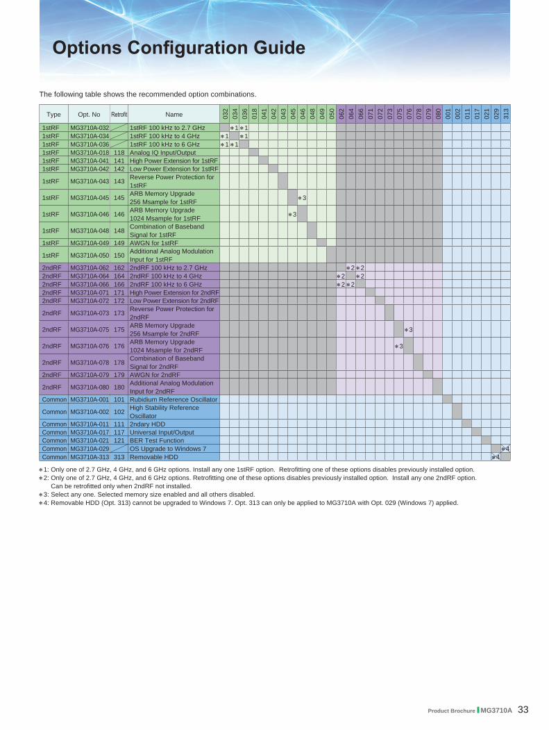
The following table shows the recommended option combinations.
Type Opt. No Retrofit Name 032
034
036
018
041
042
043
045
046
048
049
050
062
064
066
071
072
073
075
076
078
079
080
001
002
011
017
021
029
313
1stRF MG3710A-032 1stRF 100 kHz to 2.7 GHz ∗1 ∗11stRF MG3710A-034 1stRF 100 kHz to 4 GHz ∗1 ∗11stRF MG3710A-036 1stRF 100 kHz to 6 GHz ∗1 ∗11stRF MG3710A-018 118 Analog IQ Input/Output1stRF MG3710A-041 141 High Power Extension for 1stRF1stRF MG3710A-042 142 Low Power Extension for 1stRF
1stRF MG3710A-043 143 Reverse Power Protection for 1stRF
1stRF MG3710A-045 145 ARB Memory Upgrade 256 Msample for 1stRF ∗3
1stRF MG3710A-046 146 ARB Memory Upgrade 1024 Msample for 1stRF ∗3
1stRF MG3710A-048 148 Combination of Baseband Signal for 1stRF
1stRF MG3710A-049 149 AWGN for 1stRF
1stRF MG3710A-050 150 Additional Analog Modulation Input for 1stRF
2ndRF MG3710A-062 162 2ndRF 100 kHz to 2.7 GHz ∗2 ∗22ndRF MG3710A-064 164 2ndRF 100 kHz to 4 GHz ∗2 ∗22ndRF MG3710A-066 166 2ndRF 100 kHz to 6 GHz ∗2 ∗22ndRF MG3710A-071 171 High Power Extension for 2ndRF2ndRF MG3710A-072 172 Low Power Extension for 2ndRF
2ndRF MG3710A-073 173 Reverse Power Protection for 2ndRF
2ndRF MG3710A-075 175 ARB Memory Upgrade 256 Msample for 2ndRF ∗3
2ndRF MG3710A-076 176 ARB Memory Upgrade 1024 Msample for 2ndRF ∗3
2ndRF MG3710A-078 178 Combination of Baseband Signal for 2ndRF
2ndRF MG3710A-079 179 AWGN for 2ndRF
2ndRF MG3710A-080 180 Additional Analog Modulation Input for 2ndRF
Common MG3710A-001 101 Rubidium Reference Oscillator
Common MG3710A-002 102 High Stability Reference Oscillator
Common MG3710A-011 111 2ndary HDDCommon MG3710A-017 117 Universal Input/OutputCommon MG3710A-021 121 BER Test FunctionCommon MG3710A-029 OS Upgrade to Windows 7 ∗4Common MG3710A-313 313 Removable HDD ∗4
∗1: Only one of 2.7 GHz, 4 GHz, and 6 GHz options. Install any one 1stRF option. Retrofitting one of these options disables previously installed option.∗2: Only one of 2.7 GHz, 4 GHz, and 6 GHz options. Retrofitting one of these options disables previously installed option. Install any one 2ndRF option.
Can be retrofitted only when 2ndRF not installed.∗3: Select any one. Selected memory size enabled and all others disabled.∗4: Removable HDD (Opt. 313) cannot be upgraded to Windows 7. Opt. 313 can only be applied to MG3710A with Opt. 029 (Windows 7) applied.

34 Product Brochure l MG3710A
Please specify the model/order number, name and quantity when ordering.The names listed in the chart below are Order Names. The actual name of the item may differ from the Order Name.
Model/Order No. Name Remarks
MG3710A - Main frame -Vector Signal Generator
P0031A
- Standard accessories -Power Cord: 1 pcUSB MemoryInstall CD-ROM
USB2.0 Flash Driver, ≥256 MB Operation manual (PDF) and application software (IQproducer)
MG3710A-001MG3710A-002MG3710A-011MG3710A-017
MG3710A-021
MG3710A-029
MG3710A-101MG3710A-102MG3710A-111MG3710A-117MG3710A-121MG3710A-313
- Options -(Common Parts)Rubidium Reference OscillatorHigh Stability Reference Oscillator2ndary HDDUniversal Input/Output
BER Test Function
OS Upgrade to Windows 7
Rubidium Reference Oscillator RetrofitHigh Stability Reference Oscillator Retrofit2ndary HDD RetrofitUniversal Input/Output RetrofitBER Test Function RetrofitRemovable HDD
Select when ordering main frame, aging rate: ±1 × 10⁻¹⁰/monthSelect when ordering main frame, aging rate: ±1 × 10⁻⁷/yearSelect when ordering main frame, spare HDD for saving user data without Windows OSSelect when ordering main frame, Adds BNC connectors for following signals to rear panel of main frame, includes J1539A AUX Conversion Adapter (Baseband Reference Clock Input/Output, Sweep Output, Local Signal Input/Output)Select when ordering main frame, Built-in BER measurement, Bit Rate: 100 bps to 40 Mbps J1539A AUX Conversion Adapter required for Data/Clock/Enable signal inputSelect when ordering main frame, Upgrades MG3710A OS to Windows 7 (32 bit, Professional) (retrofit not supported)Retrofitted to shipped MG3710ARetrofitted to shipped MG3710ARetrofitted to shipped MG3710ARetrofitted to shipped MG3710ARetrofitted to shipped MG3710ASpare HDD for storing user data with Windows OS MG3710A with Opt. 029 (Windows 7) cannot apply Opt. 313.
MG3710A-032
MG3710A-034
MG3710A-036
MG3710A-041MG3710A-042MG3710A-043
MG3710A-045MG3710A-046MG3710A-048MG3710A-049MG3710A-050
MG3710A-018MG3710A-141MG3710A-142MG3710A-143MG3710A-145MG3710A-146MG3710A-148MG3710A-149MG3710A-150MG3710A-118
(For 1stRF)1stRF 100 kHz to 2.7 GHz
1stRF 100 kHz to 4 GHz
1stRF 100 kHz to 6 GHz
High Power Extension for 1stRFLow Power Extension for 1stRFReverse Power Protection for 1stRF
ARB Memory Upgrade 256 Msample for 1stRFARB Memory Upgrade 1024 Msample for 1stRFCombination of Baseband Signal for 1stRFAWGN for 1stRFAdditional Analog Modulation Input for 1stRF
Analog IQ Input/OutputHigh Power Extension for 1stRF RetrofitLow Power Extension for 1stRF RetrofitReverse Power Protection for 1stRF RetrofitARB Memory Upgrade 256 Msample for 1stRF RetrofitARB Memory Upgrade 1024 Msample for 1stRF RetrofitCombination of Baseband Signal for 1stRF RetrofitAWGN for 1stRF RetrofitAdditional Analog Modulation Input for 1stRF RetrofitAnalog IQ Input/Output Retrofit
Select when ordering main frame, select 1stRF frequency range, frequency cannot be changed after installationSelect when ordering main frame, select 1stRF frequency range, frequency cannot be changed after installationSelect when ordering main frame, select 1stRF frequency range, frequency cannot be changed after installationSelect when ordering main frame, increases upper limit of output signal power setting rangeSelect when ordering main frame, increases lower limit of output signal power setting rangeSelect when ordering main frame, prevents damage caused by reverse input to output connectorSelect when ordering main frame, expands ARB memory capacitySelect when ordering main frame, expands ARB memory capacitySelect when ordering main frame, adds baseband combine functionSelect when ordering main frame, adds AWGN combine functionSelect when ordering main frame, Adds BNC connector for inputting external signals to rear panel of mainframe.Select when ordering main frame, installs IQ input/output BNC connector in main frameRetrofitted to shipped MG3710ARetrofitted to shipped MG3710ARetrofitted to shipped MG3710ARetrofitted to shipped MG3710ARetrofitted to shipped MG3710ARetrofitted to shipped MG3710ARetrofitted to shipped MG3710ARetrofitted to shipped MG3710ARetrofitted to shipped MG3710A
MG3710A-062
MG3710A-064
MG3710A-066
MG3710A-071MG3710A-072MG3710A-073MG3710A-075MG3710A-076MG3710A-078MG3710A-079MG3710A-080
MG3710A-162MG3710A-164MG3710A-166MG3710A-171MG3710A-172MG3710A-173MG3710A-175MG3710A-176MG3710A-178MG3710A-179MG3710A-180
(For 2ndRF)2ndRF 100 kHz to 2.7 GHz
2ndRF 100 kHz to 4 GHz
2ndRF 100 kHz to 6 GHz
High Power Extension for 2ndRFLow Power Extension for 2ndRFReverse Power Protection for 2ndRFARB Memory Upgrade 256 Msample for 2ndRFARB Memory Upgrade 1024 Msample for 2ndRFCombination of Baseband Signal for 2ndRFAWGN for 2ndRFAdditional Analog Modulation Input for 2ndRF
2ndRF 100 kHz to 2.7 GHz Retrofit2ndRF 100 kHz to 4 GHz Retrofit2ndRF 100 kHz to 6 GHz RetrofitHigh Power Extension for 2ndRF RetrofitLow Power Extension for 2ndRF RetrofitReverse Power Protection for 2ndRF RetrofitARB Memory Upgrade 256 Msample for 2ndRF RetrofitARB Memory Upgrade 1024 Msample for 2ndRF RetrofitCombination of Baseband Signal for 2ndRF RetrofitAWGN for 2ndRF RetrofitAdditional Analog Modulation Input for 2ndRF Retrofit
Select when ordering main frame, select 2ndRF frequency range, frequency cannot be changed after installationSelect when ordering main frame, select 2ndRF frequency range, frequency cannot be changed after installationSelect when ordering main frame, select 2ndRF frequency range, frequency cannot be changed after installationSelect when ordering main frame, increases upper limit of output signal power setting rangeSelect when ordering main frame, increases lower limit of output signal power setting rangeSelect when ordering main frame, prevents damage caused by reverse input to output connectorSelect when ordering main frame, expands ARB memory capacitySelect when ordering main frame, expands ARB memory capacitySelect when ordering main frame, adds baseband combine functionSelect when ordering main frame, adds AWGN combine functionSelect when ordering main frame, Adds BNC connector for inputting external signals to rear panel of mainframe.Retrofitted to shipped MG3710A when 2ndRF not installedRetrofitted to shipped MG3710A when 2ndRF not installedRetrofitted to shipped MG3710A when 2ndRF not installedRetrofitted to shipped MG3710ARetrofitted to shipped MG3710ARetrofitted to shipped MG3710ARetrofitted to shipped MG3710ARetrofitted to shipped MG3710ARetrofitted to shipped MG3710ARetrofitted to shipped MG3710ARetrofitted to shipped MG3710A
MG3710A-ES210 MG3710A-ES310 MG3710A-ES510
- Maintenance service -2 Years Extended Warranty Service3 Years Extended Warranty Service5 Years Extended Warranty Service
Ordering Information

Product Brochure l MG3710A 35
Model/Order No. Name Remarks
MX370073A
MX370075AMX370084A
- Softwares -(Waveform pattern)DFS Radar Pattern
DFS (ETSI) Waveform PatternISDB-Tmm Waveform Pattern
(License for waveform patterns)WLAN 5.3/5.6 GHz band DFS tests (for TELEC and FCC) waveform pattern, license for main frame, manual (PDF)WLAN 5.3/5.6 GHz DFS test (ETSI) waveform pattern, license for main frame, manual (PDF)ISDB-Tmm Waveform Patterns, license for main frame, manual (PDF)
MX370101AMX370102AMX370103AMX370104AMX370105AMX370106AMX370107AMX370108AMX370108A-001MX370109AMX370110AMX370110A-001MX370111AMX370111A-002
MX370112A
- Softwares -(IQproducer)HSDPA/HSUPA IQproducerTDMA IQproducerCDMA2000 1xEV-DO IQproducerMulti-carrier IQproducerMobile WiMAX IQproducerDVB-T/H IQproducerFading IQproducerLTE IQproducerLTE-Advanced FDD OptionXG-PHS IQproducerLTE TDD IQproducerLTE-Advanced TDD OptionWLAN IQproducer802.11ac (160 MHz) Option
TD-SCDMA IQproducer
(License for IQproducer)IQproducer software, license for main frame, manual (PDF)IQproducer software, license for main frame, manual (PDF)IQproducer software, license for main frame, manual (PDF)IQproducer software, license for main frame, manual (PDF)IQproducer software, license for main frame, manual (PDF)IQproducer software, license for main frame, manual (PDF)IQproducer software, license for main frame, manual (PDF)IQproducer software, license for main frame, manual (PDF)IQproducer software, license for main frame, manual (PDF). Requires MX370108A.IQproducer software, license for main frame, manual (PDF)IQproducer software, license for main frame, manual (PDF)IQproducer software, license for main frame, manual (PDF). Requires MX370110A.IQproducer software, license for main frame, manual (PDF)IQproducer software, license for main frame, manual (PDF). Only for MG3710A. Requires MX370111AIQproducer software, license for main frame, manual (PDF)
W3580AEW2496AEW3581AE
W3596AEW3597AEW3508AEW2915AEW2916AEW2505AEW2917AEW2918AEW2798AEW2995AEW3023AEW3153AEW3221AEW3488AEW3582AE
- Optional accessories -MG3710A/MG3740A Operation Manual (Main Unit)MG3710A/MG3740A Operation Manual (IQproducer)MG3710A Operation Manual (Pre-installed Waveform Patterns)MX370073A Operation ManualMX370075A Operation ManualMX370084A Operation ManualMX370101A Operation ManualMX370102A Operation ManualMX370103A Operation ManualMX370104A Operation ManualMX370105A Operation ManualMX370106A Operation ManualMX370107A Operation ManualMX370108A Operation ManualMX370109A Operation ManualMX370110A Operation ManualMX370111A Operation ManualMX370112A Operation Manual
Booklet, for MG3710A/MG3740A Main Frame (Operation, Remote Control)Booklet, for IQproducer (Operation for Common Parts)Booklet, for Pre-installed Waveform Patterns (Usage, Detailed Parameters)
Booklet, for DFS (TELEC and FCC) Waveform PatternsBooklet, for DFS (ETSI) Waveform PatternsBooklet, for ISDB-Tmm Waveform PatternsBooklet, for HSDPA/HSUPA IQproducerBooklet, for TDMA IQproducerBooklet, for CDMA2000 1xEV-DO IQproducerBooklet, for Multi-carrier IQproducerBooklet, for Mobile WiMAX IQproducerBooklet, for DVB-T/H IQproducerBooklet, for Fading IQproducerBooklet, for LTE IQproducer/LTE-Advanced FDD OptionBooklet, for XG-PHS IQproducerBooklet, for LTE TDD IQproducer/LTE-Advanced TDD OptionBooklet, for WLAN IQproducer/802.11ac OptionBooklet, for TD-SCDMA IQproducer
J1539AZ1572AZ1594AMA24105AMA24106AMA24108AMA24118AMA24126AK240B
AUX Conversion AdapterInstallation KitStandard Waveform Pattern for BackupInline Peak Power SensorUSB Power SensorMicrowave USB Power SensorMicrowave USB Power SensorMicrowave USB Power SensorPower Divider (K connector)
Converts MG3710A rear-panel AUX connector to BNC connectorRequired when retrofitting hardware options or installing IQproducer (MX3701xxA)Latest MG3710A Pre-installed waveform pattern set for backup350 MHz to 4 GHz, Inline type, with USB A to micro-B Cable50 MHz to 6 GHz, with USB A to mini-B Cable10 MHz to 8 GHz, with USB A to micro-B Cable10 MHz to 18 GHz, with USB A to micro-B Cable10 MHz to 26 GHz, with USB A to micro-B CableDC to 26.5 GHz, K-J, 50Ω, 1 Wmax
MA1612AMP752AMA2512AJ0576BJ0576DJ0127AJ0127BJ0127CJ0322AJ0322BJ0322CJ0322DJ0004J1261BJ1261DJ0008B0635AB0657AB0636CB0645AB0671AZ0975AZ0541A
Four-Port Junction PadTerminationBand Pass FilterCoaxial Cord, 1.0 mCoaxial Cord, 2.0 mCoaxial Cord, 1.0 mCoaxial Cord, 2.0 mCoaxial Cord, 0.5 mCoaxial Cord, 0.5 mCoaxial Cord, 1.0 mCoaxial Cord, 1.5 mCoaxial Cord, 2.0 mCoaxial AdapterEthernet Cable (Shield Type)Ethernet Cable (Shield Type)GPIB Cable, 2.0 mRack Mount KitRack Mount Kit (JIS)Carrying CaseSoft Carrying CaseFront Cover for 1MW4UKeyboard (USB)USB Mouse
5 MHz to 3 GHz, N-JDC to 12.4 GHz, 50Ω, N-PFor W-CDMA, passband: 1.92 GHz to 2.17 GHzN-P · 5D-2W · N-PN-P · 5D-2W · N-PBNC-P · RG-58A/U · BNC-PBNC-P · RG-58A/U · BNC-PBNC-P · RG-58A/U · BNC-PSMA-P · SMA-P, DC to 18 GHz, 50ΩSMA-P · SMA-P, DC to 18 GHz, 50ΩSMA-P · SMA-P, DC to 18 GHz, 50ΩSMA-P · SMA-P, DC to 18 GHz, 50ΩN-P · SMA-J Conversion Adapter, DC to 12.4 GHzStraight-through, 3 mCrossover, 3 m
EIAJISHard Type. With Casters and B0671A Front CoverSoft Type
Typical (typ.): Performance not warranted. Must products meet typical performance.Nominal (nom.): Values not warranted. Included to facilitate application of product.Measured (meas): Performance not warranted. Data actually measured by randomly selected measuring instruments.Trademarks:
• IQproducer™ is a registered trademark of Anritsu Corporation.• MATLAB® is a registered trademark of The MathWorks, Inc.• CDMA2000® is a registered trademark of the Telecommunications Industry Association (TIA-USA).• The Bluetooth® mark and logos are owned by Bluetooth SIG, Inc. and are used by Anritsu under license.• Pentium® is registered trademarks of Intel Corporation or its subsidiaries in the USA and other countries.• Windows® is a registered trademark of Microsoft Corporation in the USA and other countries.• WiMAX® is a trademark or registered trademark of WiMAX Forum.• Other companies, product names and service names are registered trademarks of their respective companies.

J1539A AUX Conversion Adapter MA24106A USB Power Sensor B0636C Carrying Case(Hard type, with casters)
B0645A Soft Carrying Case
Catalog No. MG3710A-E-A-1-(5.00) Printed in Japan 5/DEC/2013 ddcw/CDT
B0671A Front Cover for 1MW4U
MG3710A with Front Cover
![Vector Signal Generator MG3710A Product Introduction · Vector Signal Generator MG3710A Features AWGN generator [Opt-049/079] AM/FM/ M/PM Functions [Standard] Additional analog modulation](https://img.dokumen.tips/doc/110x75/5eb581a18015c7750f3b383c/vector-signal-generator-mg3710a-product-introduction-vector-signal-generator-mg3710a.jpg)