Embed Size (px)
Citation preview

��Signal Conditioning Modules and Terminal BoardsTerminal Board Selection Guide 17-2
Isolated Signal Conditioning ModulesADAM-3000 Series Isolated Signal Conditioning Modules 17-4
ADAM-3011ADAM-3013ADAM-3014
Isolated Thermocouple Input ModuleIsolated RTD Input ModuleIsolated DC Input/Output Module
17-6
ADAM-3016ADAM-3112ADAM-3114
Isolated Strain Gauge Input ModuleIsolated AC Voltage Input ModuleIsolated AC Current Input Module
17-7
Isolated Digital I/O Terminal BoardsADAM-3854ADAM-3864
4-ch Power Relay Module4-ch Solid State Digital I/O Module Carrier Backplane
17-8
I/O Wiring Terminal BoardsPCLD-780PCLD-880
Screw Terminal Board with Flat CablesWiring Terminal Board with Flat Cables and Adapter
17-9
PCLD-782PCLD-782B
16-ch Opto-Isolated Digital Input Board24-ch Opto-Isolated Digital Input Board
17-10
PCLD-785/BPCLD-885
16/24-ch Relay Board16-ch Power Relay Board
17-11
PCLD-786PCLD-7216
8-ch SSR I/O Module Carrier Board16-ch SSR I/O Module Carrier Board
17-12
PCLD-788 16-ch Relay Multiplexer Board 17-13
PCLD-789D Amplifier and Multiplexer Board 17-14
ADAM-3900 Series DIN-rail Terminal Boards 17-15
Cable Accessories 17-17
Terminal Board Dimensions 17-18

17-2 Signal Conditioning Modules and Terminal Boards
Terminal Board Selection Guide Recommended Cables, I/O Wiring Terminal Boards and Isolated Digital I/O Terminals for Connecting to PCI Data Acquisition (DAQ) Cards
PCIDAQ Card Cable
I/O Wiringerminal Board
Cable Digital I/OTerminal
PCI-1751
PCI-1720U/1727U/1730U/1733/1734/1750/1760U/1761
PCI-1753
PCI-1752U/1754/1756
PCI-1240U
PCL-10168
PCL-10168
PCL-10168
PCL-10137
PCL-10268
PCL-10250
PCL-10251
PCLD-8710
PCLD-8712
ADAM-3968/50
ADAM-3968/20
ADAM-3968/50
ADAM-3968/20
ADAM-3951
ADAM-3952
ADAM-3952M
PCL-10150
PCL-10150
PCL-10120
T
PCL-10168
PCL-10120
ADAM-3968
PCI-1713U/1715U PCL-10137ADAM-3937
PCLD-881B
PCI-1784U PCI-10137H
ADAM-3937
ADAM-3968
PCLD-8751/8761/8762
PCI-1724U/1762 PCL-10162 ADAM-3962
ADAM-3968
PCL-10120
PCLD-782
PCLD-782B
PCLD-785
PCLD-785B
PCLD-885
PCLD-786
PCLD-7216
PCI-1710U/1710UL/1710HGU/1710HGL/ 1711U/1711UL/1716/1716L/1741U/1742U
PCI-1712/1712L
PCI-1721/1723/1780U
PCL-10901
PCL-1010B
ADAM-3909PCI-1714U/1714UL

www.advantech.com/productsOnline Download 17-3
8
544
109
IPC Chassis
87
Video Surveillance
6Serial Comm. Cards
Device Servers
Display Solutions
3Panel Computers
2Fanless Panel PCs
1Operator Panels
11Industrial Motherboards12
Embedded IPCs13
Mobile Computers14
IPC Peripherals15
DAQ16
Ethernet Switches
Signal Conditioning17
USB DAQ18
SBCs and Backplanes
Pre-Configured Systems
Selection Guide
Recommended Cables, I/O Wiring Terminal Boards and Isolated Digital I/O Terminals for Connecting to ISA Data Acquisition (DAQ) Cards
ISADAQ Card Cable
I/O Wiringerminal Board
Digital I/OTerminalT
PCLD-782
PCLD-782B
PCLD-785
PCLD-785B
PCLD-786
PCL-711B
PCL-818L/818HD/818HG
PCL-813B
PCL-726
PCL-727/730/836/839+
PCL-720+
PCL-722/724/731
PCL-725/733/734/735
PCLD-885
PCLD-7216
PCL-10120
PCL-10120
PCL-10137
PCL-10120
PCL-10137
PCL-10120
PCL-10120
PCL-10137
PCL-10120
PCL-10120
PCL-10150
PCL-10137
PCLD-7115
PCLD-8115
PCL-812PGPCL-10120
PCL-10120
PCLD-881B
PCLD-780
PCLD-880
PCLD-880

17-4 Signal Conditioning Modules and Terminal Boards
ADAM-3000 Series
IntroductionThe ADAM-3000 Series consist of the most cost-efficient, field configurable, isolation-based, signal conditioners on the market today. The modules are easily installed to protect your instruments and process signals from the harmful effects of ground loops, motor noise, and other electrical interferences.
Affordable Signal Isolation SolutionFeaturing optical isolation technology, the ADAM-3000 modules provide three-way (input/output/power) 1,000 VDC isolation. Optical isolation provides pin-point accuracy and stability over a wide range of operations at minimal power consumption.
Flexible Analog Data ConversionThe input/output range for the ADAM-3000 modules can be configured through switches located inside the module. The modules accept voltage, current, thermocouple or RTD as input, and pass voltage or current as output.
Thermocouple input is handled by the built-in input thermocouple linearization circuitry and a cold junction compensation function. These ensure accurate temperature measurement and accurate conversion of this information to the voltage or current output.
Features � 1,000 VDC three-way isolation � Easy input/output range configuration � Flexible DIN-rail mounting � Linearized thermocouple/RTD measurement � Low power consumption � Wide input bandwidth
Common Specifications � Isolation 1,000 VDC
� Indicators Power LED indicator � Power Requirement 24 VDC ± 10% � Case ABS � Screw Terminal Accepts 0.5 mm² ~ 2.5
mm2
1- #12 or 2- #14 ~ #22 AWG
� Operating Temperature 0 ~ 70° C (32 ~ 158° F)(ADAM-3011: 0 ~ 50° C (32 ~ 122° F))
� Storage Temperature -25 ~ 85° C(-13 ~ 185° F)
ConfigurationThe ADAM-3000 modules use 24 VDC power. This electrical power wiring can be acquired from adjacent modules, which greatly simplifies wiring and maintenance. The I/O configuration switches are located inside the modules. To reach the switches, simply remove the modules from the DIN-rail bracket by sliding the modules downward.
Modular Industrial DesignThe ADAM-3000 modules can be easily mounted on a DIN-rail, and signal wires can be connected through screw terminals. The screw terminals and input/output configuration switches are built inside the industrial grade plastic casing. With simple two-wire input/output cables, wiring is easy and reliable in harsh industrial environments.
Applications � Signal isolation � Signal transmitters � Thermocouple/RTD/strain gauge measurements � Signal amplifiers � Noise filter
www.advantech.com/productsOnline Download 17-5
8
544
109
IPC Chassis
87
Video Surveillance
6Serial Comm. Cards
Device Servers
Display Solutions
3Panel Computers
2Fanless Panel PCs
1Operator Panels
11Industrial Motherboards12
Embedded IPCs13
Mobile Computers14
IPC Peripherals15
DAQ16
Ethernet Switches
Signal Conditioning17
USB DAQ18
SBCs and Backplanes
Pre-Configured Systems
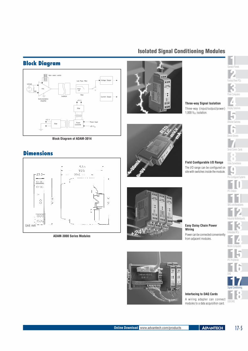
Block Diagram
+-
Voltage Output
Current Output
mV/mA
250
InstrumentationAmplifier
Gain select switch
Isolation
Low Pass Filter
Filter PowerConverter
Filter
+15 V
Power Input
+24 V DC
+15 V
ActiveLPF
Filter
PGA
Block Diagram of ADAM-3014
Unit: mm
ADAM-3000 Series Modules
Dimensions
Three-way Signal Isolation
Three-way (input/output/power) 1,000 VDC isolation.
Field Configurable I/O Range
The I/O range can be configured on site with switches inside the module.
Easy Daisy Chain Power Wiring
Power can be connected conveniently from adjacent modules.
Interfacing to DAQ Cards
A wiring adapter can connect modules to a data acquisition card.
Isolated Signal Conditioning Modules

17-6 Signal Conditioning Modules and Terminal Boards
SpecificationsThermocouple Input � Common Mode 115 dB min
Rejection � Input Type
T/C type Temperature Range (° C) Accuracy at 25° C (° C)
J -40 ~ 760 ±2K 0 ~ 1,000 ±2T -100 ~ 400 ±2E 0 ~ 1,000 ±2S 500 ~ 1,750 ±4R 500 ~ 1,750 ±4B 500 ~ 1,800 ±4
� Isolation 1,000 VDC
(Three-way) � Output Impedance 0.5 Ω � Stability ±2° C
(Temperature Drift) � Voltage Output 0 ~ 10 V
General � Certifications CE, FM � Connectors Screw terminal � Enclosure ABS � Indicators Power LED indicator � Isolation 1,000 VDC
� Power Consumption 1.4 W � Power Input 24 VDC ± 10% � Operating 0 ~ 50° C (32 ~ 122° F)
Temperature � Storage -25 ~ 85° C (-13 ~ 185° F)
Temperature
Ordering Information � ADAM-3011 Isolated Thermocouple
Input Module
ADAM-3011ADAM-3013ADAM-3014
SpecificationsRTD Input � Accuracy ± 0.1% of full range
(voltage) or +/- 0.15° C (voltage) ± 0.2% of full range (current)
� Bandwidth 4 Hz � Input CMR at DC 92 dB min. � Input Connections 2, 3 or 4 wires � Input TypeRTD type � Temperature Range (° C)
Pt 0.00385 -100 ~ 100Pt 0.00385 0 ~ 100Pt 0.00385 0 ~ 200Pt 0.00385 0 ~ 600Pt 0.00385 -100 ~ 0Pt 0.00385 -100 ~ 200Pt 0.00385 -50 ~ 50Pt 0.00385 -50 ~ 150Pt 0.00392 -100 ~ 100Pt 0.00392 0 ~ 100Pt 0.00392 0 ~ 200Pt 0.00392 0 ~ 600Ni N/A 0 ~ 100Ni N/A -80 ~ 100
� Output Range 0 ~ 5 V, 0 ~ 10 V, 0 ~ 20 mA
� Output Resistance < 5 Ω � Temperature Drift ± 30 ppm of full range
General � Certifications CE, FM � Connectors Screw terminal � Enclosure ABS � Indicators Power LED indicator � Isolation 1,000 VDC
� Power Consumption < 0.95 WPower Input 24 VDC ±10%
� Operating 0 ~ 70° C (32 ~ 158° F)Temperature
� Storage Temperature -25 ~ 85° C (-13 ~ 185° F)
Ordering Information � ADAM-3013 Isolated RTD Input Module
Isolated Thermocouple Input Module
Isolated RTD Input Module
Isolated DC Input/Output Module
ADAM-3011 ADAM-3013 ADAM-3014
SpecificationsI/O � Accuracy ±0.1% of full range
(typical) � Common Mode > 100 dB @ 50 Hz/60 Hz
Rejection � Current Input Bipolar: ±20 mA
Unipolar: 0 ~ 20 mA Input impedance: 250 Ω
� Current Output 0 ~ 20 mA � Stability 150 ppm (typical)
(Temperature Drift) � Voltage Input Bipolar input:
±10 mV, ±50 mV, ±100 mV, ±0.5 V, ±1.0 V, ±5 V, ±10 V Unipolar input: 0 ~ 10 mV, 0 ~ 50 mV, 0 ~ 100 mV, 0 ~ 0.5 V, 0 ~ 1 V, 0 ~ 5 V, 0 ~ 10 V Input impedance: 2 MΩInput bandwidth: 2.4 kHz (typical)
� Voltage Output Bipolar: ±5 V, ±10 VUnipolar: 0 ~ 10 V Impedance: < 50 ΩDrive: 10 mA max.
General � Certifications CE, FM � Connectors Screw terminal � Enclosure ABS � Indicators Power LED indicator � Isolation 1,000 VDC
(Three-way) � Power 0.85 W (voltage output)
Consumption 1.2 W (current output) � Power Input 24 VDC ±10% � Operating -10 ~ 70° C (14 ~ 158° F)
Temperature � Storage -25 ~ 85° C (-13 ~ 185° F)
Temperature
Ordering Information � ADAM-3014 Isolated DC Input/Output
Module

www.advantech.com/productsOnline Download 17-7
8
544
109
IPC Chassis
87
Video Surveillance
6Serial Comm. Cards
Device Servers
Display Solutions
3Panel Computers
2Fanless Panel PCs
1Operator Panels
11Industrial Motherboards12
Embedded IPCs13
Mobile Computers14
IPC Peripherals15
DAQ16
Ethernet Switches
Signal Conditioning17
USB DAQ18
SBCs and Backplanes
Pre-Configured Systems
SpecificationsVoltage Input
Full Range Mode 400 V 250 V 120 V
Input Voltage
AC (VRMS)
0 ~ 400 0 ~ 250 0 ~ 120
DC (V) 0 ~ 400 0 ~ 250 0 ~ 120Input Impedance 48 k 30 k 14.4 k
Voltage Output � Output Signal 0 ~ 5 VDC � Accuracy < ±1.0 % for full range � Output Impedance < 10 Ω @
operating frequency <60 Hz � Load > 10 k Ω � Ripple < 120mVp-p � Temperature 400 ppm/° C
Coefficient � Input Bandwidth 6 kHz
Power Consumption � Supply Voltage 24 VDC ± 10 % � Current Consumption 40 mA
General � Isolation Protection 1,000 VDC (output to power)
2,500 VRMS (input to output, input to power)
� Operating 0 ~ 60° C (32 ~ 140° F)Temperature
� Storage Temperature -20 ~ 70° C (-4 ~ 158° F) � Storage Humidity 5 ~ 95 %
Ordering Information � ADAM-3112 Isolated AC Voltage Input
Module
ADAM-3016ADAM-3112ADAM-3114
SpecificationsCurrent Input � AC Current Input 0 ~ 5 ARMS
� DC Current Input 0 ~ 5 A
Voltage Output � Output Signal 0 ~ 5 VDC � Accuracy < ±1.0 % for full range � Output Impedance <10 Ω @
operating frequency <60 Hz � Load > 10 kΩ � Ripple < 120 mVp-p � Temperature 400 ppm/° C
Coefficient � Input Bandwidth 10 kHz
Power Consumption � Supply Voltage 24 VDC ± 10 % � Current Consumption 40 mA
General � Isolation Protection 1,000 VDC (output to power)
2,500 VRMS (input to output, input to power)
� Operating 0 ~ 60° C (32 ~ 140° F)Temperature
� Storage Temperature -20 ~ 70° C (-4 ~ 158° F) � Storage Humidity 5 ~ 95 %
Ordering Information � ADAM-3114 Isolated AC Current Input
Module
Isolated Strain Gauge Input Module
Isolated AC Voltage Input Module
Isolated AC Current Input Module
ADAM-3112 ADAM-3114
SpecificationsI/O � Accuracy ±0.1% of full range � Bandwidth 2.4 kHz (typical) � Isolation Mode >100 dB @ 50 Hz/60 Hz
Rejection � Current Output Current: 0 ~ 20 mA
Current load resistor: 0 ~ 500 Ω (Source)
� Stability 150 ppm (typical)(Temperature Drift)
� Voltage Electrical input: ±10 mV, Specifications ±20 mV, ±30 mV, ±100 mV Excitation voltage: 1 ~ 10 VDC (60 mA max)
� Voltage Output Bipolar: ±5 V, ±10 VUnipolar: 0 ~ 10 V Impedance: < 50 Ω
General � Certifications CE � Connectors Screw terminal � Enclosure ABS � Indicators Power LED indicator � Isolation 1,000 VDC
(Three-way) � Power ≤ 1.85 W (voltage output)
Consumption ≤ 2.15 W (current output) � Power Input 24 VDC ±10% � Operating -10 ~ 70° C (14 ~ 158° F)
Temperature � Storage -25 ~ 85° C (-13 ~ 185° F)
Temperature
Ordering Information � ADAM-3016 Isolated Strain Gauge Input
Module
ADAM-3016

17-8 Signal Conditioning Modules and Terminal Boards
Features � 2,500 VRMS optical isolation � LED status indicators � Onboard fuse protection � DIN-rail mounting
SpecificationsInput ModulesField Side: � Input On/Off Voltage IAC24A series: 180 ~ 280 V/80 VRMS
Range IDC24B series: 3 ~ 32 V/1 VDC
� Input Resistance IAC24A series: 44 kΩIDC24B series: 1.5 kΩ
Logic Side: � Breakdown Voltage 30 VDC � Output Current 100 mA max. � Output Voltage Drop 0.4 V max. � Supply Current 12 mA max. � Supply Voltage 24 VDC
Output ModulesField Side: � Contact Voltage Drop 1.6 V max. � Current Rating 3 A max. (@ 25° C)
Logic Side: � Input Resistance 220 Ω � Supply Current 12 mA max. � Supply Voltage 24 V
General � Dimensions (L x H x W) 118.4 x 90 x 59 mm (4.66" x 3.54" x 2.32") � Mounting DIN-rail
Ordering Information � ADAM-3864 4-ch Solid State Module Carrier Backplane � OAC24A AC Output Module (24-280 VAC, 3 A) � ODC24 DC Output Module (5-60 VDC, 3 A) � PCLM-ODC5 Single Piece DC SSR Module (60 VDC, 3 A) � IAC24A AC Input Module (180-280 VAC) � IDC24B DC Input Module (3-32 VDC)
ADAM-3854ADAM-3864
Features � High power relays can handle up to 5 A @ 250 VAC and 5 A @ 30 VDC
� 4 single-pole double-throw (SPDT) relays � Industrial screw terminals for easy output wiring � LED status indicators � Onboard varistor protects relay contact points � DIN-rail mounting
SpecificationsI/O � Channels 4 � Contact Rating 250 VAC @ 5 A
30 VDC @ 5 A � Contact Resistance 100 mΩ � Operation Time 15 ms max. � Relay Type SPDT (Form C) � Release Time 5 ms max. � Life Expectancy 1.7 x 10⁵ at rated load
Varistor � Clamping Voltage 760 V (10 A) � Max. Applied Voltage 300 VRMS � Max. Peak Current 1,200 A for 8 ms � Varistor Voltage 470 V (current = 1 mA)
General � Connectors Screw terminals � Dimensions (L x W x H) 112.5 x 118.4 x 46 mm (4.43" x 4.66" x 1.81") � LED Indicators Status displayed for each relay � Mounting DIN-rail � Power Consumption 2.2 W � Power Input 24 VDC
Ordering Information � ADAM-3854 4-ch DIN-rail Power Relay Module
ADAM-3854 ADAM-3864
4-ch Power Relay Module4-ch Solid State Digital I/O Module Carrier Backplane

www.advantech.com/productsOnline Download 17-9
8
544
109
IPC Chassis
87
Video Surveillance
6Serial Comm. Cards
Device Servers
Display Solutions
3Panel Computers
2Fanless Panel PCs
1Operator Panels
11Industrial Motherboards12
Embedded IPCs13
Mobile Computers14
IPC Peripherals15
DAQ16
Ethernet Switches
Signal Conditioning17
USB DAQ18
SBCs and Backplanes
Pre-Configured Systems
Features
d) 4 ~ 20 mA to 1 ~ 5 VDC signal converter RAn = 0 Ω (short) RBn = 250 Ω (0.1% precision resistor) Cn = none
Pin Assignments
Ordering Information � PCLD-780 Screw Terminal Board w/ Two 20-pin Flat Cables � PCLD-880 Wiring Board w/ Two 20-pin Flat Cables & Adapter � PCL-10137-1 DB37 Cable, 1 m � PCL-10137-2 DB37 Cable, 2 m � PCL-10137-3 DB37 Cable, 3 m � PCL-10120-1 20-pin Flat Cable, 1 m � PCL-10120-2 20-pin Flat Cable, 2 m
Applications � Field wiring for analog and digital I/O channels of PC-LabCard™ products which
employ the standard 20-pin flat cable connectors or DB37 connectors (only PCLD-880)
� Signal conditioning circuits can be implemented as illustrated in the following examples:
a) Straight-through connection (factory setting) RAn = 0Ω jumper
RBn = none Cn = none
b) 1.6 kHz (3dB) low pass filter RAn = 10 KΩ RBn = none
Cn = 0.01μF
f3dB =
c) 10 : 1 voltage attenuator RAn = 9 KΩ RBn = 1 KΩ Cn = none Attenuation =
(Assume source impedance << 10 KΩ)
Screw Terminal Board with Flat Cables
Wiring Terminal Board with Flat Cables and Adapter
PCLD-780PCLD-880
� Pin to pin design � Low-cost universal screw-terminal boards for industrial applications � 40 terminal points for two 20-pin flat cable connector ports � Reserved space for signal-conditioning circuits such as low-pass filter,
voltage attenuator and current-to-voltage conversion � Table-top mounting using nylon standoffs. Screws and washers provided for
panel or wall mounting
PCLD-780 Only � Screw-clamp terminal-blocks allow easy and reliable connections � Dimensions: 102 x 114 mm (4.0" x 4.5")
PCLD-880 Only � Supports PC-LabCard™ products with DB37 connectors � Industrial-grade terminal blocks (barrier-strip) permit heavy-duty and reliable
connections � Dimensions: 221 x 115 mm (8.7" x 4.5")
IntroductionPCLD-780 and PCLD-880 universal screw-terminal boards provide convenient and reliable signal wiring for PC-LabCard™ products with 20-pin flat-cable connectors. PCLD-880 is also equipped with a DB37 connector to support PC-LabCard™ products with DB37 connectors.
PCLD-780 and PCLD-880 let you install passive components on the special PCB layout to construct your own signal-conditioning circuits. You can easily construct a low-pass filter, attenuator or current-to-voltage converter by adding resistors and capacitors onto the board’s circuit pads.
PCLD-780 PCLD-880

17-10 Signal Conditioning Modules and Terminal Boards
Features
SpecificationsIsolated Digital Input � Input Channels PCLD-782: 16
PCLD-782B: 24 � Input Range 0 ~ 24 VDC
� Input Resistance 560 Ω � Isolation Voltages 1,500 VDC min. � Threshold Voltage 1.5 VDC (VR adjustable)
General � Certifications CE � Connectors
Digital Input: Screw terminals (#12 ~ 22 AWG)Controller: PCLD-782: 1 x 20-pin box header (CN1) PCLD-782B: 1 x 20-pin box header (CN1) and 1 x 50-pin box header (CN2)
� Dimensions (L x W) PCLD-782: 3U– 205 x 114 mm (8.1" x 4.5")PCLD-782B: 4U– 220 x 132 mm (8.7" x 5.2")
� LED Indicators Indicates input logic status � Mounting 4 x screw holes for flat surface mounting
PCLD-782PCLD-782B
16-ch Opto-Isolated Digital Input Board
24-ch Opto-Isolated Digital Input Board
� Compatible with all PC-LabCard™ products with DI channels on either 20-pin flat cable or 50-pin Opto-22 compatible connectors
� 16 or 24 optically-isolated digital input channels � Built-in screw terminals for easy input wiring � LEDs indicate input logic status � Inputs buffered with voltage comparators
IntroductionPCLD-782 and PCLD-782B digital input daughterboards feature high-voltage (> 1,500 VDC) optical isolation on all inputs. PCLD-782 provides 16 input channels accessible through one 20-pin flat cable connector, which is standard on most PC-LabCard™ products. The PCLD-782B provides either 16 or 24 channels, depending on what connector you use. The PCLD-782B’s 20-pin connector lets you access 16 channels, similar to the PCLD-782, but also provides a 50-pin Opto-22 connector with access to 24 channels.
Both cards have onboard screw terminals for easy input wiring. Optically isolated signal conditioning provides isolation between separate channels, as well as between each input channel and the PC. This isolation prevents floating potential and ground loop problems while protecting the input lines from potentially damaging fault conditions.
Pin Assignments
Ordering Information � PCLD-782 16-ch Isolated DI Board w/ 1m 20-pin Flat Cable � PCLD-782B 24-ch IDI Board w/ 20-pin & 50-pin Flat Cables � PCL-10120-1 20-pin Flat Cable, 1 m � PCL-10120-2 20-pin Flat Cable, 2 m � PCL-10150-1.2 50-pin Flat Cable, 1.2 m

www.advantech.com/productsOnline Download 17-11
8
544
109
IPC Chassis
87
Video Surveillance
6Serial Comm. Cards
Device Servers
Display Solutions
3Panel Computers
2Fanless Panel PCs
1Operator Panels
11Industrial Motherboards12
Embedded IPCs13
Mobile Computers14
IPC Peripherals15
DAQ16
Ethernet Switches
Signal Conditioning17
USB DAQ18
SBCs and Backplanes
Pre-Configured Systems
16/24-ch Relay Board
16-ch Power Relay Board
Features � Compatible with PC-LabCard™ products with 20-pin digital output connector and
50-pin Opto-22 digital output connector (PCLD-785B only) � Automatic selection of control logic (PLCD-785B only): Negative logic for the
Opto-22 connector Positive logic for the 20-pin flat cable connector � Screw terminals for easy output wiring � LED status indicators
SpecificationsRelay � Channels PCLD-785: 16 (CN1, 20-pin conn.)
PCLD-785B: 16 (CN1, 20-pin conn.) 24 (CN2, 50-pin conn.)
� Contact Ratings 120 VAC @ 0.5 A, 30 VDC @ 1 A � Contact Resistance < 100 mΩ � Operation Time 5 ms max. � Insulation Resistance 100 MΩ � Life Expectancy 5 x 10⁵ @ 110 VAC /0.3 A
5 x 10⁵ @ 24 VDC /1.25 A � Relay Type SPDT (Single-Pole Double-Throw) Form C � Release Time 5 ms max.
General � Dimensions (L x W) PCLD-785: 114 x 220 mm (4.5" x 8.7")
PCLD-785B: 132 x 220 mm (5.2" x 8.7") � Power Consumption 5 V @ < 100 mA; 12 V @ 33 mA for each relay � Connectors 20-pin connector:
5 VDC: Jumper select either PC bus or external supply12 VDC: Jumper select either PC bus or external supply50-pin connector: external 12 V supply
Ordering Information � PCLD-785 16-ch Relay Board w/ One 1m 20-pin Flat Cable � PCLD-785B 24-ch Relay Board w/ 20-pin & 50-pin Flat Cables � PCL-10120-1 20-pin Flat Cable, 1 m � PCL-10120-2 20-pin Flat Cable, 2 m � PCL-10150-1.2 50-pin Flat Cable, 1.2 m
Features � Accepts 20-pin or 50-pin (Opto-22 compatible) connectors � 16 single-pole single-throw (SPST) relays � High-power relay handles up to 5 A @ 250 VAC
� Onboard varistors protect all relay contact points � Industrial screw terminals for ease of wiring � LED status indicators � 5 V/ 12 V power/status LED indicator
SpecificationsRelay � Channels 16 � Contact Rating 250 VAC @ 6 A
30 VDC @ 5 A � Contact Resistance 30 mΩ max. � Insulation Resistance 1,000 MΩ @ 500 VDC
� Life Expectancy >100,000 cycles at rated load � Relay On Time 6 ms max. � Relay Off Time 3 ms max. � Relay Type SPST (Form A), normally open
Varistor � Clamping Voltage 760 V (10 A) � Max. Peak Current 1,200 A for 8 msec. � Max. Applied Voltage 300 VRMS AC continuous � Varistor Voltage 470 V (current = 1 mA)
General � Power Consumption 12 V @ 22 mA for each relay,
352 mA if all relays energized; 5 V @ 200 mA max. � Connectors
Input: 20-pin flat cable or 50-pin Opto-22 compatible Output: Barrier strip screw terminal
� Dimensions (L x W) 205 x 114 mm (8" x 4.5") � Operating Temperature 0 ~ 60° C (32 ~ 140° F)
Ordering Information � PCLD-885 16-ch Power Relay Board w/ 20p & 50p Flat Cables
PCLD-785/BPCLD-885
PCLD-885PCLD-785/B

17-12 Signal Conditioning Modules and Terminal Boards
PCLD-786PCLD-7216
8-ch SSR I/O Module Carrier Board
16-ch SSR I/O Module Carrier Board
Features � Up to eight AC or DC solid state relay modules � Photo-coupler isolated operation � Eight external relay drivers � LED status indicators
SpecificationsAC Solid State Relays � 1 Cycle Surge 40 A � Blocking Voltage ±600 V min. � Off Leakage Current 8 mA max. � On-state Voltage 1.6 V max. � Output Rating 24 ~ 280 VAC @ 3.0 A � Turn On zero volts � Turn On/Turn Off Time < ½ cycle � Type PCLM-OAC5A
DC Solid State Relays � 1 Second Surge 5 A � OFF Leakage Current 1 mA max. � ON-state Voltage 1.4 V max. � Output Rating 5 ~ 60 VDC @ 3.0 A � Turn On/Turn Off Time 750 μs max. � Type PCLM-ODC5
External Relay Drivers � Channels 8 � Coil Driving Voltage 5 V, 12 V from PC or external source � Driver Type ULN2003, open collector type � Max. Driving Current 125 mA each channel
General � Dimensions (L x W) 205 x 114 mm (8.1" x 4.5")
Ordering Information � PCLD-786 8-ch SSR I/O Module Board w/ 20-pin Flat Cable
Note: PCLD-786 does not include SSRs. They must be ordered by selecting single piece SSR modules according to your requirements. � PCLM-OAC5A Single Piece AC SSR Module (280 VAC, 3 A) � PCLM-ODC5 Single Piece DC SSR Module (60 VDC, 3 A)
PCL-10120-1
Features � Channel status reflected by onboard LED for easy monitoring � Onboard fuse protection
SpecificationsModule Type Field Side Logic Side
Output Modules Part No. Output Voltage Rating
Output Current Rating
Input Logic and SSR Status
AC Output PCLM-OAC5A 24 ~ 280 VAC3.0 A TTL low (On)
12 ~ 280 VAC TTL high (Off)
DC Output PCLM-ODC5 5 ~ 60 VAC 3.0 A TTL low (On)TTL high (Off)
Input Modules Part No. Input On Voltage Input Off Voltage Output Logic and On/Off Status
AC Input PCLM-IAC5A 180 ~ 280 VAC < 80 V TTL low (On)TTL high (Off)
DC Input PCLM-IDC5B 3 ~ 32 VAC < 1 V TTL low (On)TTL high (Off)
Input ModulesField Side: � Input On/Off PCLM-IAC5: 90 ~ 140 V/45 VRMS
Voltage Range PCLM-IAC5A: 180 ~ 280 V/80 VRMS
PCLM-IDC5B: 3 ~ 32 V/1 VDC
� Input Resistance PCLM-IAC5: 14 kΩ, PCLM-IAC5A: 44 kΩ, PCLM-IDC5B: 1.5 kΩ
� Turn On/Off Time PCLM-IAC5: 20 msec. max., PCLM-IAC5A: 20 msec. max.PCLM-IDC5B: 100 msec. max.
Logic Side: � Breakdown Voltage 30 VDC
� Output Current 100 mA max. � Output Voltage Drop 0.4 V max. � Supply Current 12 mA max. � Supply Voltage 4 ~ 6 V
Output ModulesField Side: � Current Rating 3 A max. (@ 25° C) � Contact Voltage Drop 1.6 V max. � Turn On/Off Time PCLM-OAC series: ½ AC cycle max.
PCLM-ODC series: 100 μsec/750 μsec. max.Logic Side: � Input Resistance 220 Ω � Supply Voltage 4 ~ 6 V � Supply Current 12 mA max.
General � Logic Side Connectors 50-pin edge connector, Opto-22 compatible � Dimensions (L x W x H) 367 x 111 x 56 mm (14.4" x 4.4" x 2.2")
Ordering Information � PCLD-7216 16-ch SSR I/O Module Carrier Board
Note: PCLD-7216 does not include SSRs. They must be ordered by selecting single piece SSR modules according to your requirements.
PCLD-7216PCLD-786 PCLM-ODC5

www.advantech.com/productsOnline Download 17-13
8
544
109
IPC Chassis
87
Video Surveillance
6Serial Comm. Cards
Device Servers
Display Solutions
3Panel Computers
2Fanless Panel PCs
1Operator Panels
11Industrial Motherboards12
Embedded IPCs13
Mobile Computers14
IPC Peripherals15
DAQ16
Ethernet Switches
Signal Conditioning17
USB DAQ18
SBCs and Backplanes
Pre-Configured Systems
Features
PCLD-788 16-ch Relay Multiplexer Board
SpecificationsI/O � Channel Closed Signal TTL-level pulse � Cold-junction Sensor 24.4 mV/° C, 0 V at 0° C
Output � Contact Rating Break-before-make with 3 msec. minimum break time � Contact Resistance 200 mΩ max. � Input Channels 16 isolated differential inputs � Programming DO bit 0, 1, 2 and 3 for channel selection, DO bit 4, 5,
6 and 7 for board selection. Onboard DIP switches for board-address setting
� Max. Input Voltage 100 VDC or 100 V peak AC � Max. Switching Current 0.5 A � Max. Switching Power 10 VA � Operating Time 1 ms max. � Relay Life Expectancy 100 million cycles min. at 10 VDC and 1 mA � Release Time 1 msec. max.
General � Certifications CE � Connectors
Controller: 2 x 20-pin box header, second connector in parallel for daisy chaining I/O: Screw terminals
� Dimensions (L x W) 205 x 114 mm (8" x 4.5") � Mounting 4 x screw holes for flat surface mounting � Power Consumption 5 V @ 380 mA max.
PCLD-788 Block Diagram
� 16 to 1 channel expansion � Differential and fully isolated multiplexing � Break-before-make relay control � “Channel closed” signal for precise A/D triggering � Up to 16 PCLD-788s can be cascaded for 256 channels � Easy wiring for large channel count configuration � Onboard cold-junction circuitry for thermocouple measurement
Pin Assignments
IntroductionPCLD-788 multiplexes 16 channels into a single I/O channel of an A/D converter, voltmeter or IEEE-488-based instrument. Up to 16 PCLD-788s can be cascaded for a total of 256 fully-isolated differential channels. The PCLD-788 can be controlled by any PC-LabCard™ product via a 16-bit 20-pin digital output port, found on cards such as the PCL-711B, PCL-812PG or the PCL-818 series. Channel selection (0-15) and board selection (0-15) are done by programming the high-order four bits and low order four bits of a digital output byte from the main I/O card in use.
Ordering Information � PCLD-788 16-ch Relay MUX Board w/ Two 20-pin Flat Cables � PCL-10120-1 20-pin Flat Cable, 1 m � PCL-10120-2 20-pin Flat Cable, 2 m

17-14 Signal Conditioning Modules and Terminal Boards
Features
SpecificationsI/O � Cold-junction 24.4 mV/° C, 0 V at 0° C
Compensation � Input Channels 16 differential � Input Conditions
Gains CMRR Nonlinearity Setting Time1,000 125 dB 0.005% FSR 75 μsec.100 115 dB 0.005% FSR 15 μsec.10 105 dB 0.007% FSR 15 μsec.1 85 dB 0.015% FSR 15 μsec.
� Input Range ±10 V max. depending on the selected gain � Output Range ±10 V max. � Overvoltage Protection ±30 V continuous
General � Certifications CE � Connectors
Controller: 1 x DB37 male connector 2 x 20-pin box header for daisy chaining I/O: Screw terminals
� Dimensions (L x W) 205 x 114 mm (8.1" x 4.5") � Mounting 4 x screw holes for flat surface mounting � Power Consumption 5 V @ 30 mA max, 12 V @ 80 mA max.
Ordering Information � PCLD-789D Amplifier and Multiplexer Board w/ 1m DB37 Cable � PCL-10137-1 DB37 Cable, 1 m � PCL-10137-2 DB37 Cable, 2 m � PCL-10137-3 DB37 Cable, 3 m � PCL-10120-1 20-pin Flat Cable, 1 m � PCL-10120-2 20-pin Flat Cable, 2 m
PCLD-789D Amplifier and Multiplexer Board
� Multiplexes 16 differential inputs to one A/D input � Expands a PC-LabCard™ product’s analog inputs to 128 channels � High-grade instrumentation amplifier provides switch selectable gains of 1, 2,
10, 50, 100, 200, 1,000 � Onboard cold-junction compensation circuits for direct thermocouple
measurement � Built-in signal conditioning functions include filter, attenuator and current
shunt � Second connectors onboard allow daisy chaining � Screw-clamp terminal blocks permit easy and reliable connections
Block Diagram
Pin Assignments
IntroductionPCLD-789D is a front-end signal conditioning and channel multiplexing daughterboard for use with PC-LabCard™ product’s analog input ports. It multiplexes 16 differential input channels into a single A/D converter input channel. You can cascade up to ten PCLD-789Ds, allowing a single data acquisition card to access 160 analog input channels.
PCLD-789D has DB37 and 20-pin flat cable connectors and lets your PCL-818L or PCL-818HD access up to 128 channels without using an additional digital output cable to select channels. The PCLD-789D uses a high-grade instrumentation amplifier that provides switch-selectable gains of 1, 2, 10, 50, 100, 200 and 1,000. This amplifier lets you accurately measure low-level signals with your PC-LabCard™ product. The board also contains a cold-junction sensing circuit that allows direct temperature measurement from thermocouple transducers. A wide variety of thermocouples are supported with software compensation and linearization.

www.advantech.com/productsOnline Download 17-15
8
544
109
IPC Chassis
87
Video Surveillance
6Serial Comm. Cards
Device Servers
Display Solutions
3Panel Computers
2Fanless Panel PCs
1Operator Panels
11Industrial Motherboards12
Embedded IPCs13
Mobile Computers14
IPC Peripherals15
DAQ16
Ethernet Switches
Signal Conditioning17
USB DAQ18
SBCs and Backplanes
Pre-Configured Systems
ADAM-3900 Series DIN-rail Terminal Boards
Features � Low cost universal DIN-rail mounting screw terminal module for DAQ cards with
DB37 female connector � Case dimensions (W x L x H): 77.5 x 146.3 x 51 mm (3.1" x 5.8" x 2.0")
To Be Used WithPCI-1713U, PCI-1715U, PCI-1718HDU, PCI-1720U, PCI-1730U, PCI-1733, PCI-1734, PCI-1750, PCI-1760U, PCI-1761
ADAM-3937 DB37 DIN-rail Wiring Board
ADAM-392020-pin DIN-rail Flat Cable Wiring Board
Features � Low cost universal DIN-rail mounting screw terminal module for PC-LabCard
products with 20-pin connector � Case dimensions (W x L x H): 77.5 x 67.5 x 51 mm (3.1" x 2.7" x 2.0")
To Be Used WithPCI-1735U, PCL-711B, PCL-720+, PCL-726, PCL-727, PCL-730, PCL-812PG, PCL-816, PCL-818 Series, PCL-836
ADAM-3925DB25 DIN-rail Wiring Board
Features � Low cost universal DIN-rail mounting screw terminal module for PC-LabCard
products with DB25 connector � Screw-clamp terminal blocks allow easy and reliable connections � Case dimensions (W x L x H): 77.5 x 56.3 x 51 mm (3.1" x 2.2" x 2.0")
To Be Used WithPCI-1757UP, PCL-833
Features � Low cost universal DIN-rail mounting screw terminal module for
PC-LabCard™ products with DB9 connector � Case dimensions (W x L x H): 77.5 x 45 x 51 mm (3.1" x 1.8" x 2.0")
To Be Used WithPCI-1714U/UL, PCL-728, PCL-740, PCL-741, PCL-743B, PCL-745B
ADAM-3909DB9 DIN-rail Wiring Board
Features � Low-cost DIN-rail mounting wiring terminal module for PCI-1752/1754/1756 with
50-pin SCSI female connector � Screw-clamp terminal blocks allow easy and reliable connections � Each LED indicates its current bi-directional I/O logic status with either green or
red light � Case dimensions (W x L x H): 77.5 x 179.5 x 41.5 mm (3.1" x 7.1" x 1.6")
To Be Used WithPCI-1752U, PCI-1754, PCI-1756
Features � Low cost universal DIN-rail mounting screw terminal module for PC-LabCard™
products with 50-pin flat cable connector � Case dimensions (W x L x H): 77.5 x 146.3 x 51 mm (3.1" x 5.8" x 2.0")
To Be Used WithUSB-4751/L, PCI-1737U, PCI-1739U, PCL-722, PCL-724, PCL-731
ADAM-395050-pin DIN-rail Flat Cable Wiring Board
ADAM-395150-pin DIN-rail Wiring Board w/ LED Indicators

17-16 Signal Conditioning Modules and Terminal Boards
ADAM-3962DB62 DIN-rail Wiring Board
Features � Low cost universal DIN-rail mounting screw terminal module for DAQ cards with
DB62 female connector � Screw-clamp terminal blocks allow easy and reliable connections � Case dimensions (W x L x H): 77.5 x 124.5 x 63.5 mm (3.1" x 4.9" x 2.5")
To Be Used WithPCI-1762
ADAM-3900 Series DIN-rail Terminal Boards
ADAM-3968/5068-pin SCSI to 2 50-pin Box Header Board
Features � Low cost universal DIN-rail mounting screw terminal module for industrial
applications with 68-pin SCSI female connector � Case dimensions (W x L x H): 77.5 x 191.2 x 51 mm (3.1" x 8.4" x 2.0")
To Be Used WithPCI-1710U/UL, PCI-1710HGU, PCI-1711U/UL, PCI-1712/L, PCI -1716/L, PCI-1741U, PCI-1742U, PCI-1747U, PCI-1721, PCI-1723, PCI-1751, PCI-1753, PCI-1723, PCI-1780U
ADAM-3968/2068-pin SCSI to 3 20-pin Box Header Board
ADAM-39100100-pin DIN-rail SCSI Wiring Board
Features � Low cost universal DIN-rail mounting screw terminal module for PC-LabCard™
products with 68-pin SCSI connectors � Converts one 68-pin SCSI connector to three 20-pin connectors � Case dimensions (W x L x H): 77.5 x 80 x 54.3 mm (3.1” x 3.2" x 2.1")
To Be Used WithPCI-1751, PCI-1753
Features � Low cost universal DIN-rail mounting screw terminal module for industrial
applications with 100-pin SCSI female connector � Case dimensions (W x L x H): 80 x 230 x 42 mm (3.14" x 9.05" x 1.65")
To Be Used WithPCI-1240U, PCI-1755
ADAM-3968 68-pin DIN-rail SCSI Wiring Board
Features � Low cost universal DIN-rail mounting screw terminal module for PC-LabCard™
products with 68-pin SCSI connectors � Converts one 68-pin SCSI connector to two 50-pin Opto-22 compatible box
headers � Case dimensions (W x L x H): 77.0 x 101.0 x 54.3 mm (3.0" x 4.0" x 2.1")
To Be Used WithPCI-1751, PCI-1753

www.advantech.com/productsOnline Download 17-17
8
544
109
IPC Chassis
87
Video Surveillance
6Serial Comm. Cards
Device Servers
Display Solutions
3Panel Computers
2Fanless Panel PCs
1Operator Panels
11Industrial Motherboards12
Embedded IPCs13
Mobile Computers14
IPC Peripherals15
DAQ16
Ethernet Switches
Signal Conditioning17
USB DAQ18
SBCs and Backplanes
Pre-Configured Systems
Cable Accessories
PCL-10901PS/2 to DB9 Cable
PCL-10137/HDB37 Cable
PCL-1016868-pin SCSI Shielded Cable
PCL-10268100-Pin to Two 68-pin SCSI Cable
PCL-1010BBNC to BNC Cable, Male
PCL-1012020-pin Flat Cable
PCL-10125DB25 Cable
PCL-1012120-pin Shielded Cable
PCL-10251100-pin to Two 50-pin SCSI Cable for
PCI-1240
PCL-1015050-pin Flat Cable
PCL-10250100-pin SCSI to Two 50-pin SCSI Cable
PCL-101100SCSI Cable 100-pin Male 1m w/ Bolt Screw

17-18 Signal Conditioning Modules and Terminal Boards
Terminal Board DimensionsPCLD-782
5mm205mm5mm
107m
m5m
m5m
m
D=5.0mmX4
PCLD-782BPCLD-780
210 mm
122 mm
5 mm
5 mm
5 mm 5 mm
D=3.0mmX4
PCLD-785B PCLD-786PCLD-7855 mm5 mm
107
mm
5 m
m5
mm
220 mm
D=5.0mmX4
122
mm
5 m
m5
mm
5 mm210 mm
5 mm
D=3.0mmX4
105m
m5m
m
5mm195mm
5mm
D=5.0mmX4
PCLD-789D PCLD-880PCLD-788
105m
m5m
m5m
m
5mm 195mm 5mm
D=5.0mmX4
PCLD-7216 PCLD-8710PCLD-885
105m
m5 m
m5 m
m
5mm195mm
5mm
D=4.0mmX4
9.7mm
9.7mm
9.7mm
9.7mm
9.7mm9.7mm
9.7mm 9.7mm
105.3mm
203.23mm
D=4.5mmX4
106m
m5m
m5m
m
5mm205mm
5mm
D=5.0mmX4
6.2mm
6.2mm
6.2mm
6.2mm
5.5mm7.2mm
7.2mm 5.5mm
76.13mm
345.77mm
D=5.0mmX4
5.0mm
5.0mm
5.0mm
5.0mm
5.0mm5.0mm
5.0mm 5.0mm
104.25mm
93.25mm
D=4.5mmX4