Embed Size (px)
Citation preview

±800KV, 6000MW, HVDC MULTI-TERMINAL NER/ER – NR/WRINTERCONNECTOR-I PROJECT
HEATING, VENTILATION & AIRCONDITIONING SYSTEM (PACKAGE-A)DOC. No. : TB-343-553-040-A Rev. 01
Page 1 of 21
SECTION - 1
Intent, Design criteria, System Requirement and scope
1.1 INTENT OF SPECIFICATION
a) This specification is intended to specify the requirements for design, engineering, manufacture, inspection & testing before supply, packing, forwarding, transportation to site, unloading, stor-age, complete erection of all equipment and accessories, testing of the system, trial run, commis-sioning of the system, final painting and carrying out acceptance test of Heating, Ventilation & Air-Conditioning (HVAC) System along with its accessories and auxiliary equipments / instru-ments etc. at AGRA site as mentioned in this section and in various other sections of this specifi-cation for ±800KV, 6000 MW HVDC Multi Terminal NER/ER-NR/WR Interconnector-I Project for Power Grid Corporation of India Limited (POWERGRID).
b) Contract shall be on lump sum basis for the package. Within the scope of contract, no variation shall be admissible to Contractor so far as the inputs remain unchanged. Variations in scope due to changed inputs during contract stage shall be settled at mutually agreed rates.
c) It is not the intent to specify herein all the details of design and manufacture. However, the equipment shall conform in all respect to high standards of design, engineering and workmanship and shall be capable of performing the required duties in a manner acceptable to Purchaser / Owner, who will interpret the meaning of drawings and specifications and shall be entitled to re-ject any work or material, which in his/their judgment is not in full accordance with the specifica-tions.
d) The bidder shall be deemed to have understood completely all the tender drawings and docu-ments and quoted accordingly.
e) In case of any deviation, the bidder shall indicate separately the deviations clause-wise with re-spect to the specification in the ‘Schedule of Deviation’ as described in Section 5. Deviations in any other form including clarifications / assumptions / etc will not be considered and it will be construed that the bid conforms strictly to the specification.
f) This specification makes it obligatory for the contractor to arrange / obtain necessary approval / clearance from statutory organizations wherever applicable for the plant / machinery / sub-systems under the scope specified.
g) The system shall be designed to suit the extreme of outside conditions as given in “Section 3” of the specification.
h) The term ‘Owner’ appearing in this specification shall refer to Power Grid Corporation of India Limited (POWERGRID), the term ‘Purchaser’ shall refer to Bharat Heavy Electricals Limited (BHEL) and the term ‘Contractor’ shall refer to the successful Bidder.

±800KV, 6000MW, HVDC MULTI-TERMINAL NER/ER – NR/WRINTERCONNECTOR-I PROJECT
HEATING, VENTILATION & AIRCONDITIONING SYSTEM (PACKAGE-A)DOC. No. : TB-343-553-040-A Rev. 01
Page 2 of 21
1.2 INTRODUCTION
A comprehensive Heating, Ventilation & Air-Conditioning (HVAC) system for all areas of the main & auxiliary service buildings and other buildings at AGRA converter station shall be provided to ensure satisfactory operation of the HVDC system under the range of climatic conditions to which the station may be subjected.
Buildings/ Areas requiring environment control shall include:
a) 1 no. Main Service Building(common building for pole 1 & 2)
b) 2 nos. Additional service buildings(separate building for pole 3 & 4 each) c) 4 nos. Valve Cooling Rooms d) 1 no. Pump house e) 4 nos. LV switchgear buildings f) 4 nos. MV switchgear buildings
1.3 DESIGN CRITERION
a) All air conditioned Spaces shall be designed
• To achieve an inside temperature of 24⁰C±1⁰C (Dry Bulb) & relative humidity of 47±5% • Ventilation rate for a/c areas shall be 1.5 air changes per hour or 15 CFM per person; whi-
chever is higher.
b) Non AC areas shall be provided with ventilated systems with the following design requirements:
• Sanitary Facilities : 12 air changes per hour
• Other areas : 4.5⁰C above outdoor ambient temperature and air changes per hour shall not be less than 10.
Room Lighting Load for rooms to be ventilated shall be taken as 10-15 W/m2 of area of room.
c) Outdoor conditions at AGRA, which shall be considered for design of above systems:
Sl. No. Description Temp. (⁰C)
1 Maximum dry bulb one hour average 50
2 Maximum dry bulb 24 hour average 40
3 Annual mean dry bulb temperature 30
4 Minimum dry bulb one hour average 0
5 Maximum wet bulb one hour average 33
6 Dry bulb temperature for low ambient condition 33
7 Wet bulb temperature for low ambient condition 23
1.4 AIR-CONDITIONING SYSTEM
Air-conditioning shall be provided on continuous basis in the following areas:

±800KV, 6000MW, HVDC MULTI-TERMINAL NER/ER – NR/WRINTERCONNECTOR-I PROJECT
HEATING, VENTILATION & AIRCONDITIONING SYSTEM (PACKAGE-A)DOC. No. : TB-343-553-040-A Rev. 01
Page 3 of 21
a) Main Service Building (common building for pole 1 & 2)
b) Additional service buildings (separate building for pole 3 & 4 each)
1.4.1 MAIN SERVICE BUILDING
1.4.1.1 Control Room Areas of Main Service Building
Following areas of the Main Service Building (refer Drg. TB-2-306-316-210 rev. 06) shall be pro-vided with an air conditioning system (AC-1) consisting of two (2), each 100% capacity, chilled water type air conditioning units; one operating and one stand-by. The units shall be factory-assembled, factory-tested Microprocessor Controlled packaged Air Cooled Water Chilling Units with Unit Mounted Starter.
Ground floor i) Pole 1 Control Equipment Room ii) Pole 2 Control Equipment Room iii) Bipole 1 Control Equipment Room iv) Bipole 2 Control Equipment Room
First Floor v) Station Control Equipment Room vi) Telecom room vii) Pole 1 Valve Control Room viii) Pole 2 Valve Control Room ix) Control Room (Video Screen room)
Second Floor x) Control Room (Video Screen room)
Both units shall be interconnected so that, in the event of breakdown of one unit, the stand-by unit can be placed into service. Stand-by and operating units shall be alternated monthly for reg-ular operation. The operation of the units shall be automatically controlled including sequential start and stop with single command.
1.4.1.2 Other Areas of Main Service Building
A separate air conditioning system (AC-2) shall be provided for other areas of main service build-ing. This shall also consist of two (2), each 100% capacity, chilled water units; one operating and one stand-by. These units shall also be chilled water type as stated above for AC-1. This system shall take care of the following areas of main service building:
Ground Floor a) Battery Room 1 & 2 b) LVDC & Charger Room 1 & 2 c) Passage d) Reception

±800KV, 6000MW, HVDC MULTI-TERMINAL NER/ER – NR/WRINTERCONNECTOR-I PROJECT
HEATING, VENTILATION & AIRCONDITIONING SYSTEM (PACKAGE-A)DOC. No. : TB-343-553-040-A Rev. 01
Page 4 of 21
e) Meeting Room
First Floor f) Electronic Store room g) Simulator Training room h) Workstation room i) Training/Workshop room j) Document room k) Inc. Sec room l) Inc. room m) Conference room n) Electronic workshop o) All Staff room p) Passage
Second Floor q) Meeting room or Office area r) Documentation room s) Passage t) Lobby u) Staff room
Both units shall be interconnected so that, in the event of breakdown of one unit, the stand-by unit can be placed into service. Stand-by and operating units shall be alternated monthly for reg-ular operation. The operation of the units shall be automatically controlled including sequential start and stop with single command.
1.4.1.3 System Description
Each of the two Air-conditioning system shall be complete with all the relevant appurtenances in-cluding compressor, air handling unit, condenser, fans, casing, filters, piping, valve, controls, in-struments, MCC control panel, chilled water pumps, ducting, diffuser, grills, insulation, fresh air unit, dampers etc.
All four Air-cooled water chillers for both the systems alongwith two (2), each 100% capacity, chilled water pumps for each system shall be placed adjacent to main service building whereas double skin type air-handling units (2 x 100% basis per system) shall be accommodated in their respective AHU rooms on ground floor of main service building.
Outlet of the air-handling units shall be collected in a common plenum chamber through flexible canvass connection & volume control dampers. The conditioned air is then distributed to various AC areas through supply air duct running above false ceiling having diffuser with volume control damper.
Return air from “control room areas” and “other areas of service building” shall be collected and taken to their respective AHU rooms through return air ducts with diffusers (without VCD) where

±800KV, 6000MW, HVDC MULTI-TERMINAL NER/ER – NR/WRINTERCONNECTOR-I PROJECT
HEATING, VENTILATION & AIRCONDITIONING SYSTEM (PACKAGE-A)DOC. No. : TB-343-553-040-A Rev. 01
Page 5 of 21
it will be mixed with a fixed amount of fresh air before being circulated again. A fresh air unit with pre & fine filter shall be provided in each of the AHU rooms.
Both the supply & return air ducts shall be thermally insulated with fibre glass insulation having a thickness of 25mm (min.) and normal density of 24kg/m3. Anti-sweating insulation material shall be supplied and installed on all air conditioning (supply as well as return) ductwork. The insula-tion shall have a fire retarding vapour barrier jacketing and shall be covered with aluminium jack-eting. Acoustic insulation shall be provided on SA duct upto 5 mtrs length from AHU outlet.
Strip heater banks of adequate capacity alongwith thermostat, humidistat and geyserstat etc shall be provided in the supply air duct for winter heating and monsoon reheating. Also, solenoid op-erated fire dampers shall be provided in all the supply air and return air paths, which shall close on FIRE signal from fire alarm panel.
1.4.1.4 Control Philosophy
a) Operating Controls
i) The air conditioning system shall run round the clock.
ii) A stable room inside temperature as specified shall be maintained by controlling the flow of chilled water through flow regulating valves provided at the inlet of the cooling coils of the respective AHUs.
iii) The room relative humidity shall be maintained by following means:
- Heating through duct mounted strip heaters, which shall be operated by humidistat. - Humidification through Pan humidifier, which shall be operated by humidistat.
iv) All the control shall be made effective through local control panels mounted on the respective chiller units. Besides, integration to BMS system shall be made so that all the controls are effective from remote through BMS console located inside control room.
b) Safety Controls
Following safety controls shall be incorporated with the system:
i) High pressure cut out (condensing pressure)
ii) Low oil pressure cut out
iii) Overload trip of compressor motor
iv) Overload trip of chilled water pump motors (for chilled water system only)
v) Overload trip of AHU fan motor
vi) High temperature and "no air flow cut out" with strip heaters.
vii) High temperature cut out for Pan humidifier heaters.
viii) Low temperature cut out through pilot solenoid valve
±800KV, 6000MW, HVDC MULTI-TERMINAL NER/ER – NR/WRINTERCONNECTOR-I PROJECT
HEATING, VENTILATION & AIRCONDITIONING SYSTEM (PACKAGE-A)DOC. No. : TB-343-553-040-A Rev. 01
Page 6 of 21
c) Interlocks
i) The Compressor shall not start, if any of the following is not running:
- Condenser fan - Air Handling Unit
ii) The strip heaters shall not start if AHUs is not working.
iii) Thermostat to cut off strip heater if temperature is high.
iv) Pan humidifier heater to cut in only when water level in the humidifier tank is sufficient.
v) AC system shall be tripped on signal from the Purchaser’s Fire Alarm Panel.
vi) Solenoid operated fire dampers in supply and return air path shall close on signal from Purchaser’s Fire Alarm Panel.
1.4.2 ADDITIONAL SERVICE BUILDINGS
Air conditioning, for the following areas on first floor of additional service buildings (pole 3 & 4), shall be provided using Air Cooled ductable Package AC units of adequate capacities:
a) Pole Control Equipment Room b) Elec. Com Storage Room c) Documentation Room d) Battery room (Ground floor) e) DCDB & Charger room (Ground floor) f) Staff Room
1.4.2.1 System Description
Package air conditioners (indoor evaporator unit) shall be located inside AHU room whereas the condensing unit shall be kept on the terrace outside AHU room. The two are connected through copper refrigerant piping.
Outlet discharge of indoor units shall be collected in a common plenum chamber through flexible canvass connection & volume control dampers. This conditioned air is then distributed to above mentioned rooms through supply air duct along with diffuser (with volume control damper) run-ning above false ceiling. Return air from all these areas shall be collected in the void above false ceiling & shall be taken back to AHU room where it will be mixed with a fixed amount of fresh air before being circulated again. A fresh air unit with pre & fine filter shall be provided in the AHU room.
Supply air duct shall be thermally insulated with fibre glass insulation having a thickness of 25mm (min.) and normal density of 24kg/m3. Anti-sweating insulation material shall be supplied and in-stalled on it. The insulation shall have a fire retarding vapour barrier jacketing and shall be cov-ered with aluminium jacketing. Acoustic insulation shall be provided on SA duct upto 5 mtrs length from outlet of indoor units.
Strip heater banks of adequate capacity alongwith thermostat, humidistat and geyserstat etc shall
±800KV, 6000MW, HVDC MULTI-TERMINAL NER/ER – NR/WRINTERCONNECTOR-I PROJECT
HEATING, VENTILATION & AIRCONDITIONING SYSTEM (PACKAGE-A)DOC. No. : TB-343-553-040-A Rev. 01
Page 7 of 21
be provided in the supply air duct for winter heating and monsoon reheating. Also, solenoid op-erated fire dampers shall be provided in all the supply air and return air paths, which shall close on FIRE signal from fire alarm panel.
MCC for AC units, pan humidifiers, heaters, fire dampers etc shall be kept in the AHU room itself.
1.4.2.2 Control Philosophy
Same as mentioned under cl. 1.4.1.4 above.
1.5 VENTILATION SYSTEM
Apart from areas specified above under cl. 1.4, other areas of main and additional service build-ings, MV & LV switchgear buildings, and pump house shall be provided with mechanical ventila-tion through exhaust fans/ supply air fans as elaborated in subsequent clauses in this section.
1.5.1 NON-AC AREAS
Other non AC areas of the HVDC converter station at AGRA shall be provided with wall mounted axial flow exhaust fans complete with drive motor and accessories. These areas are as under:
A Main Service Building: i) Mechanical Workshop ( Ground floor) ii) Toilets (Ground, first & second floor) iii) Storage Room (First floor) iv) Pantry room (First floor)
B Additional Service Building: i) Toilets (Ground & first floor)
ii) Pump house iii) MV switchgear buildings iv) LV switchgear buildings v) Valve Cooling Rooms
1.6 INTERFACE REQUIREMENT
a) Air conditioning System
Air-conditioning systems at various locations, as described above, shall be interfaced with Purchas-er’s Fire detection and alarm (FDA) system in those areas to initiate the following actions in case of fire:
To shut down the AHU/ AC units. To close the fire dampers in supply & return air paths.
Provision of required potential free contacts has been made in FDA system, which shall be wired up by HVAC contractor in his panels.
Provision of required potential free contacts has been made in Aspiration system, which shall be wired up by HVAC contractor in his panels.

±800KV, 6000MW, HVDC MULTI-TERMINAL NER/ER – NR/WRINTERCONNECTOR-I PROJECT
HEATING, VENTILATION & AIRCONDITIONING SYSTEM (PACKAGE-A)DOC. No. : TB-343-553-040-A Rev. 01
Page 8 of 21
b) HVAC system shall be interfaced for control and monitoring of all the equipments through Purchas-er’s Building Management System (BMS). Requirements of integration with BMS are listed under Annexure-A to this Section. HVAC Contractor shall make provision of potential free contacts in his panels accordingly. Besides, contractor shall keep provision of 25% spare contacts for further repeti-tion to a remote location.
1.7 POWER SUPPLY ARRANGEMENT
a) Separate MCCs for AC plants of main & additional service buildings shall be kept in the respective AHU rooms.
b) Ventilation fans in main & additional service buildings and other buildings shall be fed though lo-cal lighting boards. Contractor shall supply individual starters for each fan.
c) Each MCC shall have provision of double incomer with a bus coupler and necessary electrical in-terfacing. Provision of 25% spare feeders of each type and rating shall be kept.
1.8 SCOPE
The scope of the work under the contract shall be deemed to include all such items, which although not specifically mentioned in the bid documents and/or in the bidder’s proposal, but are required to make the equipment/ system complete for its safe, efficient, reliable and trouble free operation.
1.8.1 Scope of supply
Supplies for Air-Conditioning & Ventilation System at AGRA broadly consist of the following:
Sr. No.
System Areas Covered
1 Air Conditioning System a) Main Service Building (1 No.) b) Additional Service Buildings (2 nos.)
2 Ventilation System a) Valve cooling rooms (4 Nos.)
b) MV & LV Switchgear buildings (4 nos. Each)
c) Fire Fighting Pump House building (1 no.)
d) Non-AC areas of main & additional service build-
ings
3 Electricals a) MCC for Chilled water air conditioning System
b) Instruments & sensor as required
c) Local Push Button station as required
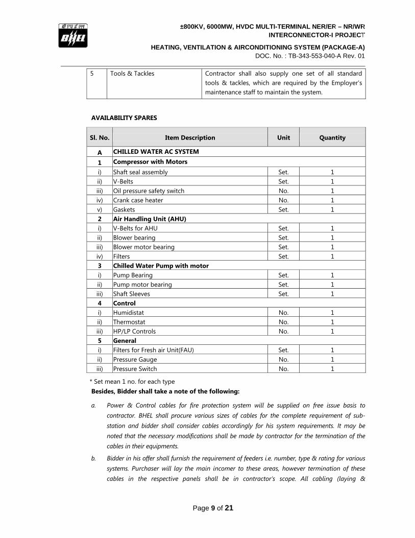
4 Availability Spares Contractor shall supply the spare parts required to meet the specified guaranteed availability, and shall in-clude such spare parts in the scope of supply.
A list of spare parts to meet the guaranteed reliability & availability requirements is given below, which shall be considered by the bidder in his price bid.
±800KV, 6000MW, HVDC MULTI-TERMINAL NER/ER – NR/WRINTERCONNECTOR-I PROJECT
HEATING, VENTILATION & AIRCONDITIONING SYSTEM (PACKAGE-A)DOC. No. : TB-343-553-040-A Rev. 01
Page 9 of 21
5 Tools & Tackles Contractor shall also supply one set of all standard tools & tackles, which are required by the Employer's maintenance staff to maintain the system.
AVAILABILITY SPARES
Sl. No. Item Description Unit Quantity
A CHILLED WATER AC SYSTEM
1 Compressor with Motors i) Shaft seal assembly Set. 1 ii) V-Belts Set. 1 iii) Oil pressure safety switch No. 1 iv) Crank case heater No. 1 v) Gaskets Set. 1 2 Air Handling Unit (AHU)i) V-Belts for AHU Set. 1 ii) Blower bearing Set. 1 iii) Blower motor bearing Set. 1 iv) Filters Set. 13 Chilled Water Pump with motor i) Pump Bearing Set. 1 ii) Pump motor bearing Set. 1 iii) Shaft Sleeves Set. 1 4 Control i) Humidistat No. 1 ii) Thermostat No. 1iii) HP/LP Controls No. 1 5 General i) Filters for Fresh air Unit(FAU) Set. 1 ii) Pressure Gauge No. 1iii) Pressure Switch No. 1
* Set mean 1 no. for each type Besides, Bidder shall take a note of the following:
a. Power & Control cables for fire protection system will be supplied on free issue basis to contractor. BHEL shall procure various sizes of cables for the complete requirement of sub-station and bidder shall consider cables accordingly for his system requirements. It may be noted that the necessary modifications shall be made by contractor for the termination of the cables in their equipments.
b. Bidder in his offer shall furnish the requirement of feeders i.e. number, type & rating for various systems. Purchaser will lay the main incomer to these areas, however termination of these cables in the respective panels shall be in contractor’s scope. All cabling (laying &

±800KV, 6000MW, HVDC MULTI-TERMINAL NER/ER – NR/WRINTERCONNECTOR-I PROJECT
HEATING, VENTILATION & AIRCONDITIONING SYSTEM (PACKAGE-A)DOC. No. : TB-343-553-040-A Rev. 01
Page 10 of 21
termination) further from these panels to various equipments and for control & interlocking of these equipments shall be in contractor’s scope.
c. Since laying & termination of all power & control cables is in contractor’s scope, supply of cable accessories such as lugs, glands, cable tags & markers etc. shall be included by the bidders in their offers.
d. Necessary cable trays will be supplied on free issue basis to the contractor, however necessary hardware for fixing the same on walls or elsewhere shall be included by the bidders in their offers.
e. Earthing material viz. GS flat & wire will also be supplied on free issue basis to contractor; however requirement shall be given by the bidders in their respective bids.
f. Contractor shall submit valid Type test report for approval by owner. Fresh type test of equipment is not envisaged.
g. Valid Type Test reports (not more than 5 years old) for degree of protection of electrical panels shall be submitted by contractor for approval during contract stage. Type test need not be done specially. However, in case the type test reports are found un-satisfactory, tests shall be carried out afresh by contractor without any additional cost implication to BHEL/ Powergrid.
h. Finishing colours shall be RAL 7035 for indoor panels/cubicles and RAL 7032 for outdoor panels/cubicles.
i. Bidder shall choose the makes from among the POWERGRID COMPENDIUM OF APPROVED VENDORS (refer Enclosures to this specification), which are also available on POWERGRID website on the Internet. In case, no vendor is specified in the list against a particular item, only reputed makes available in the market shall be considered. All such makes shall be subjected to acceptance of POWERGRID. No additional price implication shall be made to BHEL on account of non-acceptance of proposed makes by POWERGRID.
1.8.2 Scope of services
Erection, Testing & Commissioning (ETC) requirements
a) The scope of ETC shall include receipt of material at site, safe storage of material, handling of equipment/material at site, erection of equipment /material at site including fabrication, equipment and system testing, commissioning of the entire system, conducting performance guarantee tests to the satisfaction of Owner/ Purchaser and handing over of the system to Owner/ Purchaser. All material, consumables plus tools & tackles required for completion of ETC work shall be arranged by the Bidder.
b) Piping from water tap-off to inlet of pan humidifier. Water tap-off shall be provided by the purchaser at one point inside AHU room of main & auxiliary service buildings.
c) Piping from overflow of pan humidifier & for disposal of condensate from AHUs to the nearest drain point.
±800KV, 6000MW, HVDC MULTI-TERMINAL NER/ER – NR/WRINTERCONNECTOR-I PROJECT
HEATING, VENTILATION & AIRCONDITIONING SYSTEM (PACKAGE-A)DOC. No. : TB-343-553-040-A Rev. 01
Page 11 of 21
d) Cable laying & termination between Fire Alarm Panel (FAP) or Aspiration system panel to various HVAC panels for effecting trippings of AC units in case of fire.
e) Laying and termination of power and control cables for the equipment under the scope of this specification.
f) Laying & fixing of cable trays on walls or elsewhere.
g) All electrical components shall be properly earthed by the contractor to the nearest earthmat riser of the Owner / Purchaser.
h) The contractor shall arrange all machinery -tools & tackles and consumables required for erection of the system.
i) Contractor shall ensure that sufficient quantity of commissioning spares is made available for timely completion of commissioning of the system. The contractor shall furnish a list of commissioning spares that will be brought by him. The unused commissioning spares shall be returnable to the Contractor.
j) Conducting Performance Guarantee tests to the satisfaction of Owner / Purchaser.
k) After completion of erection and commissioning of the system, the contractor shall train site engineers of Purchaser/Owner so that they are fully conversant with both electrical and mechanical part of the package.
l) The contractor shall furnish the operation and maintenance manual specifically compiled for each of the sub-stations. The draft O&M manual shall be submitted within 20 weeks after award of contract. The O&M manual shall contain the following information:
i) Description of the system and equipment with design particulars
ii) Instruction for erection.
iii) Instruction for operation, maintenance and repair.
iv) Recommended inspection practices and inspection schedule.
v) Ordering information for all replaceable parts.
vi) Recommendation for type of lubricants and frequency of lubrication.
1.9 CIVIL WORKS
Major civil works such as room & foundations for various HVAC equipments shall be in purchaser’s scope. Wall openings at suitable locations for duct, refrigerant/drain piping, fresh air unit & ventilation fans shall be made by the contractor. Associated civil works such as grouting, filling up crevices/cut outs etc during installations of equipments shall also be in contractor’s scope. Any other damage caused to civil works during ETC work of the equipment/system shall be made good to the original finish by the contractor at extra cost to the purchaser.
±800KV, 6000MW, HVDC MULTI-TERMINAL NER/ER – NR/WRINTERCONNECTOR-I PROJECT
HEATING, VENTILATION & AIRCONDITIONING SYSTEM (PACKAGE-A)DOC. No. : TB-343-553-040-A Rev. 01
Page 12 of 21
1.10 EXCLUSIONS (FREE ISSUE SUPPLY/ SERVICE TO CONTRACTOR BY BHEL)
a) Supply of power & control cables for the system.
b) Supply of necessary cable trays for laying power and control cables, wherever required.
c) Supply of GI flat for earthing of equipments. GI wire, if required, shall be supplied by
contractor.
d) Supply & installation of ventilation system for Gas Genset building. It shall be provided by the
genset supplier.
e) Various rooms and foundations for locating air conditioning & ventilation equipments.
f) Supply & installation of false ceiling in buildings, wherever required.
g) Underdeck insulation of the air conditioned areas.
1.11 INSPECTION & TESTING
All the equipments shall be inspected prior to dispatch in line with relevant IS, approved GTP/ drawing and technical specification.
1.12 PERFORMANCE TEST
The contractor shall submit PG test procedure during detailed engineering stage for owner’s ap-proval. PG test shall be carried out at site during peak summer condition in line with approved PG test procedure in presence of purchaser’s & owner’s representatives.
1.13 UTILITIES AVAILABLE
Water & electricity shall be provided at one point and contractor shall make necessary provisions for distribution to its various points of usages.
1.14 HANDING & TAKING OVER
It is the responsibility of the Contractor to run and maintain the plant till it is handed over to the owner. Contractor shall assist purchaser to hand over the plant to owner.

±800KV, 6000MW, HVDC MULTI-TERMINAL NER/ER – NR/WRINTERCONNECTOR-I PROJECT
HEATING, VENTILATION & AIRCONDITIONING SYSTEM (PACKAGE-A)DOC. No. : TB-343-553-040-A Rev. 01
Page 13 of 21
ANNEXURE-A INTEGRATION WITH BMS
Control and Monitoring of all Air-conditioning Systems including Chillers, Condensers, Chilled Water Pumps, AHU's, valve hall pressurization Fans, motorized dampers, etc. shall be done by use of a reputed software based system. This fully computerized and automatic Building management system (BMS) is in other’s scope of supply & installation; however HVAC contractor shall make provision of necessary inputs to integrate HVAC system with BMS. I/O POINT SUMMARY FOR BMS The minimum control & monitoring required for the BMS (Air Conditioning & Ventilation System) is sum-marized in the I/O list below: 1. AIRCONDITIONING SYSTEM
A. CHILLERS Chiller - Enable Chiller Run Status Chiller Refrigerant Leak Alarm Fault Alarms Capacity Control Chilled Water Reset Chiller Compressor Current Monitoring Individual Chiller' Supply Temperature Differential Pressure across Chiller In & out
B. CHILLED WATER PUMPS Primary Chilled Water Pumps Primary Chilled Water Pump Start/Stop Primary Chilled Water Pump Status Pump Manual Operation Status
C. HEADER CIRCUIT Common Chilled Water Supply Temperature Common Chilled Water Return Temperature Chilled Water Flow Meter Differential Pressure Chiller In and Out Outside Air Temperature and RH
D. AIR HANDLING UNITS AHU Start/stop Low Speed AHU Start/Stop High Speed AHU Blower Status AHU Manual Operation Status AHU Filter Status AHU Return Air Temperature & RH AHU modulate Chilled Water Valve AHU supply air temperature AHU supply air humidity
E. EXPANSION TANK Chilled Water Low Level Monitoring

±800KV, 6000MW, HVDC MULTI-TERMINAL NER/ER – NR/WRINTERCONNECTOR-I PROJECT
HEATING, VENTILATION & AIRCONDITIONING SYSTEM (PACKAGE-A)DOC. No. : TB-343-553-040-A Rev. 01
Page 14 of 21
SECTION 2
Equipment Specification
2.1 GENERAL
a) The design and construction of complete system shall comply with the latest applicable In-dian/British/American Standards/Codes.
b) All mechanical works shall satisfy the general technical requirements and shall be designed to op-erate in the ambient/system conditions specified in Section 3.
c) The requirements mentioned under this clause are indicative and minimum for the system. Any other item/ service required to complete the work for safe and sound operation of system shall be provided and installed by the bidder at no extra cost to the purchaser. The bidder may bring out such requirement(s) suitably.
The following requirements shall be met by the equipment supplied by Contractor:
i) The equipment shall be designed and constructed for safe, proper and continuous operation un-der all conditions described or implied in the Specification, without undue strain, vibration, corro-sion or other operating difficulties.
ii) Parts shall be designed and supported to permit free expansion and contraction without causing leakage, distortion or excessive strain on the equipment.
iii) Parts subject to wear, corrosion or other deterioration or requiring adjustment, inspection or re-pair shall be readily accessible and capable of easy removal for repair or replacement.
iv) All heavy components shall be provided with convenient means for slinging or handling during in-stallation and maintenance.
v) No auxiliary system shall be common to both poles. Emergency connections between poles shall be provided but the two systems shall be separated in the normal mode of operation. This princi-ple of pole separation shall apply to all systems including water supply. However common fire fighting pumps can be used.
vi) Within a system, stand-by and/or duplicate equipment shall be provided with a minimum of two for each major component such as, pumps, heaters, strainers, fans or operationally separate cells of cooling towers or heat exchangers. Thus, loss of a single element of auxiliary plant shall not re-sult in any loss of converter rating under any combination of load and ambient conditions. Loss of a second element of auxiliary plant of the same type and duty shall not reduce the station capa-bility by more than the equivalent of the output of one pole.
vii) Duplicate and/or stand-by equipment shall automatically, based on a predetermined cycle, be brought on the system such as to allow an equal wear and tear.
viii) Unless otherwise specified, all equipment serviced by a duplicate or stand-by shall, on detection of failure, get automatically isolated. The corresponding duplicate or stand-by equipment shall automatically take over the failed equipment.
±800KV, 6000MW, HVDC MULTI-TERMINAL NER/ER – NR/WRINTERCONNECTOR-I PROJECT
HEATING, VENTILATION & AIRCONDITIONING SYSTEM (PACKAGE-A)DOC. No. : TB-343-553-040-A Rev. 01
Page 15 of 21
ix) Loss of any equipment or system shall automatically be alarmed at BUILDING MANAGEMENT SYSTEM.
x) The principles detailed above need not be applied to systems upon which the conversion equip-ment does not depend for operation.
xi) No mechanical equipment shall be installed on the roof of the converter building, i.e. valve halls and service building.
2.2 AIR CONDITIONING UNIT DETAILS
2.2.1 Compressor
The compressor shall be hermetic or semi-hermetic reciprocating/scroll type complete with drive package, oil heater, safety controls, shut off valves, purge valve, by-pass safety valve etc. It shall be complete with oil level port, oil drain plug with magnet and adequately sized inspection covers and oil level sight glass. The lubrication system shall be Forced Feed complete with reversible gear oil pump adequately sized oil filters, oil coolers etc. as required. Electrically operated crank case oil heater suitable for specified power supply shall be provided. Heater shall be automati-cally actuated when the compressor is stopped, either by a relay or by means of auxiliary contacts on the compressor motor starter. The compressor shall be equipped with automatic unloading device, to ensure for partial load starting of the compressor as well as multi-step capacity control.
Compressor shall be complete with required accessories, such as shut off valves, pipe flanges , suction strainer, pressure gauge and following controls:-
• Anti Freeze Thermostat • Solid state operating Thermostat • Liquid Line strainer • Water flow switches at the outlet of cooler • H.P., L.P. Oil pressure cut outs and pressure gauges. • TX-valve or valves as required. • Refrigerant solenoid valve or valves as required. • Fan control Thermostat • Inherent motor protectors.
The condenser Casing shall be heavy gauge, Zinc coated steel, backed on enamel weatherised for outdoor installation; Panel shall be easily removable for complete accessibility. Condenser Coils shall be seamless copper tubes in staggered formation and shall be expanded into aluminium fins. A Sub-cooling coil circuit shall be integral part of condenser. The fans shall be propeller type direct drive by independent motors and shall be positioned for vertical air discharge. The blades shall be dynamically and statically balanced and provided with heavy gauge anodised guards. Fan motors shall be permanent - split capacitor induction type and provided with perma-nently lubricated drive. The motors shall be isolated from the unit by resilient rubber mounts.
The Chiller shall be shell and tube, multi-pass, direct expansion type. The shell shall be of welded construction fitted with steel sheets on either side. The tubes shall be supported in the shell by
±800KV, 6000MW, HVDC MULTI-TERMINAL NER/ER – NR/WRINTERCONNECTOR-I PROJECT
HEATING, VENTILATION & AIRCONDITIONING SYSTEM (PACKAGE-A)DOC. No. : TB-343-553-040-A Rev. 01
Page 16 of 21
adequate stiff supports to eliminate vibration and noise. The tube ends shall be properly ex-panded in the tube sheet to prevent leakage of refrigerant.
The refrigerant heads shall be made of cast iron and the faces ground to close tolerances to pre-vent leakage of refrigerant between passes and between the circuits in case of a multi-circuit cooler. The cooler shall be factory insulated to avoid condensation on coil. The cooler shall be complete in all respect and shall include:-
• Filter drier • Relief valve, charging connection with valve and drain valve, sight glass, moisture liquid
indicator. • Water inlet and outlet connections with stem type thermometer and dial type pressure
gauges. • Supports for mounting. • Steel sockets between each baffle complete with removable plug to drain entrapped wa-
ter from chiller shell.
The refrigerant piping between Compressors, Chiller and Condenser shall be of heavy gauge cop-per with brazed joints. The circuit shall include sight glass, moisture indicator, solenoid valves, thermostatic expansion valves, filter dryers and necessary shut off valves with charging connec-tions.
2.2.2 Air Handling Unit
The air handling units shall be Double skin, draw through/ blow through type, modular construc-tion and shall include filter section, fan section, coil section and mixing box (wherever required). The AHU shall be made of Double skin design with main structure made of 16G GI powder coated/ extruded Aluminium frame work. The panels shall be double skin sandwich type with minimum 24G GI powder coated external sheet and 24G GI powder coated internal sheet with 25mm thick insulation material in between. All sections shall be bolted to each other with neo-prene rubber gasket.
The fan shall be double inlet, double width type. The wheel & housing shall be fabricated from heavy gauge galvanised steel. The impeller & fan shaft shall be statically and dynamically bal-anced. Fan housing with motor shall be mounted on a common steel base mounted inside the air handling housing on anti-vibration springs mounts. The fan outlet shall be connected to casing with the help of fire retardant flexible canvass. The fan shall be complete with multi V belt drive, belt guard and adjustable motor mounting base.
The cooling coil shall be of seamless copper tubes, with aluminium fins. The tubes shall be stag-gered in the direction of air flow. The headers shall be complete with water in/out connections. Air velocity across the cooling coil shall not exceed 2.5 m/sec.
Each system shall have pre-filter of 90% efficiency down to 10 microns at the inlet of AHU and a micro-vee filter of 99% efficiency down to 5 microns at the inlet of AHU.

±800KV, 6000MW, HVDC MULTI-TERMINAL NER/ER – NR/WRINTERCONNECTOR-I PROJECT
HEATING, VENTILATION & AIRCONDITIONING SYSTEM (PACKAGE-A)DOC. No. : TB-343-553-040-A Rev. 01
Page 17 of 21
The drain pan of AHU shall be double skin internally insulated with 25mm expanded polystyrene. The drain pan shall be constructed of 0.8mm thick CRCA sheet power coated on outside and 0.63 mm GI sheet on inside with 25 mm thick insulation in between. The cooling coil and condensate pan shall be assembly mounted on slides such that cooling coil and condensate pan can be wholly removed for maintenance.
The cooling coils, standard filters, etc., shall all be housed in a separate enclosure of suitable size and length. The inspection doors shall have double synthetic rubber seals doors and locking ar-rangements.
Each unit shall be provided with factory assembled humidifier section to accommodate hot dipped galvanised pan humidifier complete with immersion heater of suitable capacity, low level cut-out, float valve, sight glass. The humidifier section shall be coated with heat hardened poly-ester based power paint.
2.2.3 CHILLED WATER PUMPS
The chilled water pump sets shall be split casing type with suction and discharge flange connec-tions and drip proof squirrel cage induction motor. Pump set shall be as per IS: 1520-1960, IS: 5120, IS-9079, and IS-325. Drive ratings, at 50oC ambient, shall be 10% in excess of maximum BHP of Pump plus transmission losses
2.2.4 MCC & Controls
Each unit shall be capable of being controlled locally and remotely from the station control room. Additional contacts shall be provided to effect interlocking of each unit with the fire detection system.
The locally mounted control panel shall be installed in the casing of the unit and wired complete with magnetic starters for both fans and motors, high and low pressure cut outs, oil pressure safety switch, and motor winding protectors.
The remote control panel shall provide central control of cooling and shall be installed in the con-trol room. Indication lights for unit functions shall be provided including system “COOL-AUTO-OFF” and fan “ON-OFF-TRIP”. The main thermostat shall be located in the control room.
All conduit and wiring between controls and operating units shall be provided. All wiring in rooms and areas where Air conditioning has been provided shall have concealed wiring.
2.2.5 Ductwork and Related Accessories
All ductwork including related accessories required for the proper distribution of air for the air conditioning system and for the ventilation system shall be provided.
The valve hall & DC hall ventilation system shall have ducts for complete air circulation, air inlet and air outlet along with all accessories. No part of the housing/room/civil work shall be used as supply and/or return air path of ventilation system.

±800KV, 6000MW, HVDC MULTI-TERMINAL NER/ER – NR/WRINTERCONNECTOR-I PROJECT
HEATING, VENTILATION & AIRCONDITIONING SYSTEM (PACKAGE-A)DOC. No. : TB-343-553-040-A Rev. 01
Page 18 of 21
Duct and fittings shall be made of galvanized cold rolled steel sheets. Ductwork connections to units shall be made with fireproof flexible material. Supply, return and outdoor air ductwork and mixing sections with manual dampers, and by pass damper arrangement shall be shop or field fabricated.
Under deck insulation of at least 50 mm. thick shall be provided to all the air conditioned rooms where the ceiling is exposed to direct sunlight. Sun films also shall be provided on the glass por-tion.
The air velocity in the supply section shall not be more than 460 m/min. The air velocity in the re-turn section shall not be more than 180 m/min. The minimum thickness of GI sheets shall be as follows:
Dimension of the duct Gauge up to 750 mm 24G from 751 - 1500 mm 22G from 1501 - 2250 mm 20G above 2250 mm 18G
Dampers
The dampers shall be provided in every main branch so arranged that they can be adjusted with a quadrant on the outside of the duct and can be permanently fixed in position after the system is properly balanced.
Damper regulator sets shall be cadmium plated stamped steel and shall be mounted directly on the ducts without insulation. Spacer studs shall be provided for insulated ducts.
Louver Dampers
Louver dampers shall be provided where required and shall be carefully made to ensure tight shut-off and accurate positioning, manually or by damper motors. They shall be constructed with opposed blades, and shafts shall be fitted in “Oiltite” or approved equal bearings.
Louvers
Louvers in walls for ventilating units shall be provided.
Louvers shall be extruded aluminium, with interlocking mullions, integral caulking slots and rein-forced corners. Louvers shall be at least 100 mm wide and complete with 50 mm diamond galva-nized bird screens.
Hangers
Ducts shall be permanently hung from rigid supports with the horizontal runs level and the verti-cal runs plumb. Additional hangers shall be installed at all bends, transformations and take-off connections. Hanger rods shall be sway-braced by means of crossed rods at not more than 6 m spacing.

±800KV, 6000MW, HVDC MULTI-TERMINAL NER/ER – NR/WRINTERCONNECTOR-I PROJECT
HEATING, VENTILATION & AIRCONDITIONING SYSTEM (PACKAGE-A)DOC. No. : TB-343-553-040-A Rev. 01
Page 19 of 21
Vibration Isolation
Floor mounted equipment having a frequency of vibration of 1200 cycles per minute or less, shall be mounted on spring isolators with sound absorbing pads.
Sleeves
Where ducts pass through walls or partitions, suitable sleeves of a gauge not less than that of the duct shall be provided.
Ducts through plenum chambers shall be made air-tight by caulking with asbestos rope between the duct and sleeve.
Thermal Insulation
Anti-sweating insulation material shall be supplied and installed on all air conditioning (supply as well as return) ductwork. The insulation shall have a fire retarding vapour barrier jacketing and shall be covered with aluminium jacketing. Insulation thickness shall not be less than 25 mm Fi-breglass insulation shall have a normal density of 24kg/m3.

±800KV, 6000MW, HVDC MULTI-TERMINAL NER/ER – NR/WRINTERCONNECTOR-I PROJECT
HEATING, VENTILATION & AIRCONDITIONING SYSTEM (PACKAGE-A)DOC. No. : TB-343-553-040-A Rev. 01
Page 20 of 21
SECTION – 3
Project Details and General Technical Requirements
Please refer TB-343-316-000, Rev-01 “General Technical requirement –section-3”and relevant clauses of technical specification


±800KV, 6000MW, HVDC MULTI-TERMINAL NER/ER – NR/WRINTERCONNECTOR-I PROJECT
HEATING, VENTILATION & AIRCONDITIONING SYSTEM (PACKAGE-A)DOC. No. : TB-343-553-040-A Rev. 01
Page 21 of 21
4 ENCLOSURES TO SPECIFICATION
4.1 GA for AC Switchyard at AGRA Converter Station (Drg. No.-TB-0-343-320-00, Rev-05)
4.2 Fire Fighting cum water supply pump house (Drg. No. 5517-3-83-601, Rev-00)
4.3 Architectural layout for Valve hall Ventilation & Valve Cooling Building (drg no: 5517-3-
80-201, Rev-0)
4.4 Architectural layout for Main Service Building (drg no: 5517-3-43-007, Rev-01)
4.5 Architectural layout for Relay Building (drg no: 3-80-001, Rev-0)
4.6 Architectural layout for Additional Service Building
4.7 Architectural layout for MV & LV Switchgear buildings