Embed Size (px)
Citation preview

INSTRUCTION MANUAL
Serial No._____________________
112014
World Precision Instruments
ww
w.w
pii
nc.c
om
SI-CTS200Signal Conditioning Amplifi er System for the Cell Tester

Cell Tester
II WORLD PRECISION IN STRU MENTS

SI-CTS200
WORLD PRECISION IN STRU MENTS iii
Copyright © 2014 by World Precision Instruments, Inc. All rights reserved. No part of this publication may be
reproduced or translated into any language, in any form, without prior written permission of World Precision
Instruments, Inc.
CONTENTSABOUT THIS MANUAL ............................................................................................................................... 1INTRODUCTION ........................................................................................................................................... 2
Platform ...................................................................................................................................................... 2Electronics .................................................................................................................................................. 3Cautions and Warnings ........................................................................................................................ 3Parts List ..................................................................................................................................................... 4Unpacking ................................................................................................................................................. 4
INSTRUMENT DESCRIPTION .................................................................................................................... 5Signal Conditioning Amplifi er for the SI-CTS200 ......................................................................... 5
Front Panel .......................................................................................................................................... 5Back Panel ........................................................................................................................................... 6
SI-KG7TWE Force Transducer ............................................................................................................. 6SI-NAMO Nanomotor ............................................................................................................................ 8Rotating Cuvette ...................................................................................................................................... 9SI-BAM21-LCB ........................................................................................................................................10
Features ..............................................................................................................................................10How the Amplifi er Works .............................................................................................................10Notes and Warnings ......................................................................................................................10Front Panel ........................................................................................................................................11
SI-CISB .......................................................................................................................................................12Notes and Warnings ......................................................................................................................12Front Panel ........................................................................................................................................13
SI-PF100 ...................................................................................................................................................14SI-AOSUB .................................................................................................................................................15
Front Panel ........................................................................................................................................15SI-TCM2B .................................................................................................................................................16Features ....................................................................................................................................................16
Front Panel ........................................................................................................................................17System Setup ..........................................................................................................................................18
Assembling the Platform ..............................................................................................................18Connecting the Signal Conditioning Amplifi er System ......................................................23
OPERATING INSTRUCTIONS ...................................................................................................................26Turning the System On .......................................................................................................................26Using the SI-BAM21-LCB ....................................................................................................................26
Calibrating the SI-BAM21-LCB ...................................................................................................26Realigning the Nanomotor Mechanical Zero Position ......................................................28Making Measurements..................................................................................................................28Setting System Gain Factor ..........................................................................................................29
Using the Programmable Filter ........................................................................................................29Using the Anti-Oscillation Unit .........................................................................................................29
Adjusting the Anti-Oscillation Filter ...........................................................................................29

Cell Tester
IV WORLD PRECISION IN STRU MENTS
Using the Temperature Control Module ........................................................................................31Understanding the Display ..........................................................................................................31Setup ....................................................................................................................................................32Choosing a Display Mode ............................................................................................................32Setup Menu .......................................................................................................................................33Adjusting the Setpoint ...................................................................................................................33Setting Alarms ..................................................................................................................................33Changing the Backlight Level for the Display .......................................................................34Enabling/Disabling the Alarms...................................................................................................34Using the USB Port Output ..........................................................................................................34
Holding Cells with Microtweezers ...................................................................................................35Attaching Cells to Glass Microrods .................................................................................................36
MAINTENANCE ............................................................................................................................................37ACCESSORIES ...............................................................................................................................................38TROUBLESHOOTING .................................................................................................................................39SPECIFICATIONS ..........................................................................................................................................40INDEX .............................................................................................................................................................41DECLARATION OF CONFORMITY .........................................................................................................42WARRANTY ..................................................................................................................................................43
Claims and Returns ..............................................................................................................................43
SI-CTS200
WORLD PRECISION IN STRU MENTS 1
ABOUT THIS MANUAL
The following symbols are used in this guide:
This symbol indicates a CAUTION. Cautions warn against actions that can cause damage to equipment. Please read these carefully.
This symbol indicates a WARNING. Warnings alert you to actions that can cause personal injury or pose a physical threat. Please read these carefully.
NOTES and TIPS contain helpful information.
Fig. 1–SI-CTS200 allows you to work with a single, living cell or fi ber without damaging it.

Cell Tester
2 WORLD PRECISION IN STRU MENTS
Fig. 2–The Signal Conditioning Amplifi er System is a fl exible chassis that is specifi cally confi gured for the SI-CTS200 (Cell Tester).
INTRODUCTION PlatformAll living systems can be studied from several perspectives. We can examine the entire organism or a specifi c organ system. We can characterize a single organ in a system or a type of tissue in an organ or the cells that make up that tissue. To completely understand any system, all of these perspectives must be considered. Often, entirely different systems are needed in a parallel experimental paradigm. The Cell Tester accomplishes this on one platform.
The Cell Tester can, without any changes, be used for one single living cell, for a small multi-cellular preparation and for single or larger skinned muscle strip preparations. Translational experiments from the single living cells to the intact multi-cellular level can be accomplished. For example, using the Cell Tester, the infl uence of the connective tissue on muscle function can be distinguished from the clean muscle work for the fi rst time. Conversely, skinning allows a direct comparison between the living cell response and a cell, whereby the subcellular contractile proteins are studied with full experimental access to cell signalling and cellular biochemistry.
The Cell Tester gives you the comprehensive ability to investigate and characterize the physiological, bio-mechanical and bio-physical properties of single isolated living cells and extend these fi ndings to the sub- and multi-cellular level. Features of this system include:
• Integral microtweezer apparatus facilitates cellular attachment• Two integrated piezo manipulators are standard• Bio-compatible adhesive included• Unique rotational stage–easy cellular alignment, improved experimental
throughput• Ultra-quiet force transducer included

SI-CTS200
WORLD PRECISION IN STRU MENTS 3
• Linear displacement motor stretches or compresses cells with 25nm precision• Fits ANY inverted microscope• Use native cuvette or ANY 35mm glass bottom dish
ElectronicsThe Signal Conditioning Amplifi er System provides a fl exible electronic platform intended to process the transduction of mechanical signals, the fi ltering of transducer outputs and the control of motor positions.
The system consists of an 8-channel, rack-mountable frame that includes an ultra quiet, shielded power supply. Outputs are routed internally to the inputs of other modules. If you prefer, the module outputs may be routed to external outputs on the front panels. The system has a small footprint and may be stacked to provide as many channels as you need.
When the system is ordered with an SI-CTS200 (Cell Tester) system, the Signal Conditioning Amplifi er System (chassis) is confi gured with an SI-BAM21-LCB (Optical Transducer Amplifi er), an SI-CISB (Cell Tester Position Controller), an SI-AOSUB (Anti Oscillation Unit), an SI-TCM2B Temperature Controller and two expansion slots. The Position Controller and the Temperature Controller each requires two slots on the chassis backplane.
NOTE: The system is fl exible and confi gurable. A variety of modules are available for the Signal Conditioning Amplifi er System, and you can mix and match the modules to suit your requirements. For this manual, we will only discuss the modules used with the SI-CTS200 system.
This Signal Conditioning Amplifi er System offers eight expansion slots, confi gured at the factory to meet your requirements.
NOTE: The system for the SI-CTS200 is confi gured at the factory. If you need to add additional modules, contact Technical Support at 941.371.1003 or [email protected].
Three Cell Tester systems are sold:• SI-CTS200A includes an SI-NAMO Nanomotor with microtweezer, SI-KG7TWE
Force transducer with microtweezer, Signal Conditioning Amplifi er System with SI-BAM21-LCB Optical Transducer Amplifi er, SI-AOSUB Anti-Oscillation Unit, SI-TCM2 2-Channel Temperature Controller, SI-CISB Nanomotor Position Controller ( piezo motor driver), glass fi ber tissue mounts, MyoTakTM biocomaptible adhesive and LABTRAX 8/16 data acquisition system.
• SI-CTS200B includes the SI-CTS200A components plus the base unit with rotating cuvette.
• SI-CTS200 includes: SI-CTS200B components plus two 3-axis motorized micromanipulators with a controller.
Cautions and WarningsWARNING: TURN OFF THE SIGNAL CONDITIONING AMPLIFIER SYSTEM AND UNPLUG IT FROM THE POWER OUTLET BEFORE REMOVING OR INSTALLING ANY MODULE IN THE UNIT.
Cell Tester
4 WORLD PRECISION IN STRU MENTS
Parts ListAfter unpacking, verify that there is no visible damage to the instrument. Verify that all items are included:
(1) Signal Conditioning Amplifi er System with the SI-BAM21-LCB, SI-PF100 or SI-AOSUB, SI-CISB and SI-TCM2B modules
(1) Power cord
(1) Base plate with rotating cuvette (SI-CTS200 and SI-CTS200B only)
(2) Micromanipulators with controller (SI-CTS200 only)
(1) 0.9mm hex wrench for fi ne adjustment of the force transducer and nanomotor
(1) 3mm hex wrench
(1) 13661 Potentiometer Adjustment Tool
(1) Force Transducer Assembly with microtweezer
(1) Nanomotor Assembly with microtweezer
(1) 97204 Pulser assembly for SI-AOSUB calibration
(5) 20µL vials of MyoTakTM biocompatible adhesive (ships separately)*
(1) 100µL vials of Pre-Coat for MyoTak
(1) Instruction Manual
*The MyoTak included with your order consists of 5 vials of 20µL aliquots each. With daily testing, this supply will last fi ve weeks. Additional aliquots of MyoTak may be ordered, as needed. MyoTak must be express shipped on dry ice and MUST be stored in a freezer immediately upon receipt. If the gel is exposed to temperatures above 4ºC, it polymerizes and quickly sets, making it unsuitable for its intended use. Contact WPI to schedule delivery of the MyoTak included with your system. Use the purchase order number of your system when requesting your fi rst shipment of MyoTak.
UnpackingUpon receipt of this instrument, make a thorough inspection of the contents and check for possible damage. Missing cartons or obvious damage to cartons should be noted on the delivery receipt before signing. Concealed damage should be reported at once to the carrier and an inspection requested. Please read the section entitled “Claims and Returns” on page 43 of this manual. Please contact WPI Customer Service if any parts are missing at 941.371.1003 or [email protected].
Returns: Do not return any goods to WPI without obtaining prior approval (RMA # required) and instructions from WPI’s Returns Department. Goods returned (unauthorized) by collect freight may be refused. If a return shipment is necessary, use the original container, if possible. If the original container is not available, use a suitable substitute that is rigid and of adequate size. Wrap the instrument in paper or plastic surrounded with at least 100mm (four inches) of shock absorbing material. For further details, please read the section entitled “Claims and Returns” on page 43 of this manual.

SI-CTS200
WORLD PRECISION IN STRU MENTS 5
INSTRUMENT DESCRIPTION
Signal Conditioning Amplifi er for the SI-CTS200
Front Panel
Power SwitchExpansion
Slots
AntiOscillation
Unit
OpticalTransducerAmplifier
Cell TesterPosition
ControllerTemperature
Controller Power SwitchExpansion
Slots
AntiOscillation
Unit
OpticalTransducerAmplifier
Cell TesterPosition
ControllerTemperature
Controller
Fig. 3–The front panel of a Signal Conditioning Amplifi er System confi gured for a Cell Tester shows the SI-BAM21-LCB, the Position Controller and the SI-AOSUB.
Optical Transducer Amplifi er–The SI-BAM21-LCB powers the force transducer and converts the output of the transducer to an amplifi ed analog voltage that is proportional to the force applied to the transducer. The output signal can be multiplied by a factor of 1, 2, 5 or 10 to provide better resolution for a minimal change in applied force.
Position Controller–The Cell Tester nanomotor and force transducer are extremely sensitive. The SI-CISB position controller is used to open and close the microtweezers on both devices, and to control the movement of the nanomotor used to stretch or release the cell or fi ber held by the microtweezers.
Programmable Filter (SI-PF100)–(Not shown) This low pass fi lter may be used in place of an Anti-Oscillation unit to program the cutoff equivalence. You may select a Bessel or a Butterworth fi lter and set the cutoff frequency.
Anti-Oscillation Unit (SI-AOSUB)–Each force transducer has a resonance frequency at which it vibrates. The SI-AOSUB, when properly tuned to that resonance frequency, removes the resonance noise from the output signal of SI-BAM21-LCB transducer amplifi er.

Cell Tester
6 WORLD PRECISION IN STRU MENTS
Temperature Control Module–When temperature control is required, the SI-TCM2B is used. It can control two cuvettes simultaneously, using digital control to maintain a constant temperature. It has both high and low alarm warnings which are user defi ned.
Expansion Slots–These empty slots allow room for four other Signal Conditioning Amplifi er System modules to be added in the future.
Power Switch–This system has two power switches, one on the back panel and one on the front. Both switches must be on to power the system.
Back Panel
Master Power SwitchFuse HousingPower ConnectorFig. 4–The back panel of the Signal Conditioning Amplifi er System has a master power switch that is usually left on.
Power Connector–Insert the power cord into the power connector, and plug the cord into a standard wall AC outlet.
Fuse Housing–This housing contains the fuse for the chassis system.
Master Power Switch–The signal conditioning chassis distributes sub-regulated DC power (12V) to the individual modules through a backplane of the chassis. For convenience, the unit has two power switches, and both must be on to power the system. All the modules power on/off simultaneously. When your system is set up, just leave this power switch in the on (I) position
NOTE: The 16 plugs marked with A or B are for future development. They are not used at this time.
SI-KG7TWE Force TransducerThe SI-KG7TWE is a specialized transducer, which is capable of measuring the force of a single muscle cell. It is equipped with a pair of electronically controlled microtweezers, which hold onto the cell during force determinations and perturbations of the cell with load and length changes.
SI-CTS200
WORLD PRECISION IN STRU MENTS 7
A skinned skeletal muscle cell can be held directly by uncoated microtweezers, and an intact skeletal muscle cell needs to be held by microtweezers that are coated with a special biocompatible adhesive ( MyoTakTM). However, heart cells cannot be held directly by coated or uncoated microtweezers. For the SI-KG7TWE transducer to hold a heart cell, the ends of the cell are attached to glass rods coated with MyoTak. The microtweezers are used to grasp the coated glass rod to which the heart muscle cell is glued (Fig. 5). In heart cell studies, the microtweezer/transducer assembly, as well as the microtweezer/nanomoter assembly that holds the glass rod on the other end of the cell, are rotated 90º.
Fig. 5– The microtweezers hold a muscle cell, but a cardiac myocyte must be fi xed to a coated glass rod.
The microtweezers are opened or closed by rotating the Force Transducer Tweezer Control potentiometer on the front panel of the Position Control module. The use of this potentiometer to gradually open and close the microtweezers controls the pressure exerted on the end of the cell according to the experimental needs. Remote electronic control of the microtweezers prevents the vibration that could damage the cell.
Fig. 6–(Left) The force transducer (sensor assembly) is packaged in a sturdy box to protect the sensitive assembly, and it should always be stored in the case to protect the delicate tip.Fig. 7–(Right) The force transducer has a colored band on one cable to indicate which connector plugs into the Transducer Tweezer port on the Position Control module.

Cell Tester
8 WORLD PRECISION IN STRU MENTS
SI-NAMO NanomotorLike the SI-KG7TWE force transducer, the SI-NAMO nanomotor is equipped with microtweezers for grasping the end of the cell that is opposite the transducer. The microtweezers are operated in the same manner as the ones on the transducer. Through feedback circuitry in the Position Control module, the position of the nanomotor is controlled accurately so that cell attached to the nanomotor can be stretched, relaxed or loaded according to the experimental protocol.
Frequency 50HzAmplitude 20μ
Input Signal 2V
Frequency 5HzAmplitude 20μ
Input Signal 2V
Fig. 8–Length response to a rectangular input signals.
Fig. 9–(Left) The nanomotor assembly is shipped in a sturdy box.Fig. 10–(Right)The nanomotor, like the force transducer, has a tiny microtweezer that is highly sensitive.

SI-CTS200
WORLD PRECISION IN STRU MENTS 9
Rotating CuvetteThe complete system utilizes a unique rotating bath to dramatically improve experimental throughput. The rotating bath is designed to orient cells in the XY plane so that no physical manipulation of the position of the cell itself is required prior to capture by the grabbing devices attached to the force sensor and linear actuator.
Fig. 11–The cuvette rotates to allow for precise positioning of the cells to be mounted
This bath has two interchangeable inserts. The fi rst holds any 35mm glass bottom dish (WPI #FD35-100). When coating tweezers or glass rods with MyoTak biocomaptible adhesive, insert a Fluorodish into the holder and place it in the rotating cuvette. When fi nished, remove the insert and dispose of the Fluorodish. Then, insert the native cuvette insert containing the live cells.
Fig. 12–(Left) The two inserts fi t into the rotating stage holder. (Center) The 35mm glass bottom dish fi ts into the fi rst insert. (Right) The insert and dish are placed in the rotating cuvette.

Cell Tester
10 WORLD PRECISION IN STRU MENTS
SI-BAM21-LCBThe SI-BAM21-LCB KG Optical Force Transducer Amplifi er is used in conjunction with the SI-H tissue bath and muscle physiology systems. The SI-BAM21-LCB powers the force transducer and converts the output of the transducer to an amplifi ed analog voltage that is proportional to the force applied to the force transducer. The output signal can be multiplied by a factor of 1, 2, 5 or 10 to provide better resolution for a minimal change in applied force.
NOTE: An optional factory setting increases the multiplier by a factor of 10, allowing the signal to be multiplied by 10, 20, 50 and 100.
NOTE: The SI-BAM21-LC is the standalone version of this optical force transducer amplifi er.
FeaturesThe SI-BAM21-LCB amplifi er works with KG optical force transducers to:
• Generate an analog output (-10VDC to +10VDC) that is proportional to the force applied to the tissue sample.
• Supply a DC voltage that powers the KG force transducer to which it is connected.
How the Amplifi er WorksIn a typical setup, a muscle is held by a force transducer. The force transducer is connected to the SI-BAM21-LCB. As the muscle contracts or releases, the force transducer converts the force into an electrical current signal which is proportional to the force applied to the force transducer. The SI-BAM21-LCB converts the current signal into a voltage signal that can be displayed on the screen of the recording device.
Before initiating an experiment, the SI-BAM21-LCB must fi rst be zeroed. This sets the baseline for measurements to follow.
The output signal is buffered and multiplied by 1, 2, 5 or 10, depending on the Gain switch setting on the front panel of the amplifi er module. The X10 setting is useful when output signals are extremely small. Finally, the force proportional signal is sent through the output amplifi er circuit.
The analog output has a range of –10V to +10V that drives a data acquisition system, multimeter or oscilloscope.
Notes and WarningsNOTE: The SI-BAM21-LCB is only designed for use with KG optical force transducers. Use with any other type of transducer may cause damage to either the transducer or the amplifi er or both.

SI-CTS200
WORLD PRECISION IN STRU MENTS 11
Front Panel
Zero Button
Gain Switch
Data Acquistion Output
Force Transducer Connection
Offset Adjustment Switch
Offset Adjustment LEDs
Zeroing LED
Gain Indicator LEDs
Gain Calibration Potentiometer
Digital Interface Connection
Fig. 13–SI-BAM21-LCB KG Optical Force Transducer Amplifi er
Zero Button–When pressed, the SI-BAM21-LCB output comes close to zero and the Zeroing LED illuminates. Before any measurements are taken, the SI-BAM21-LCB should be zeroed to establish a baseline value for the force transducer.
Offset Adjustment Switch–This toggle switch permits the position of the baseline to be adjusted after the baseline is zeroed. Press and hold the toggle switch to the left if you want to raise the baseline. Or, press and hold the toggle switch to the right to lower the baseline. If the baseline is more that 0.3V above zero, the High LED illuminates, and if it is less than –0.3V, the Low LED illuminates. When the baseline is within 0.3V of zero, the LEDs are off.
Gain Switch–Under normal conditions, the Gain switch is set to X1. The output of the force transducer can be amplifi ed by a factor of 2, 5 or 10. Press the Gain switch to toggle between the gain settings. A Gain Indicator LED illuminates to show which gain factor is applied. Larger gains are essential when working with extremely small forces.
Gain Calibration Potentiometer– This potentiometer can be used to maximize the output of the amplifi er for the anticipated range of forces to be measured. Use the provided potentiometer adjustment tool (WPI#13661) to calibrate the output of the amplifi er to the

Cell Tester
12 WORLD PRECISION IN STRU MENTS
range of forces that will be measured by the transducer. See "Calibrating the SI-BAM21-LCB" on page 26.
Data Acquisition Output–Connect a data acquisition system like WPI’s Lab-Trax-8/16 to this BNC connector to record the raw SI-BAM21-LCB voltage output. For test purposes, a multi-meter or oscilloscope may be connected using a standard BNC cable (WPI #2851).
Force Transducer Connection–An SI-KG7TWE force transducer is plugged into this DIN connector. Align the pins, and insert the connector until it is fully seated.
Digital Interface–This connection is a legacy interface for classic SI-H equipment.
NOTE: When the SI-CTS200 electronics are confi gured at the factory for the Cell Tester systems, the signal is routed internally from the SI-BAM21-LCB module to the SI-AOSUB module. The Force Output connection on the front of the SI-BAM21-LCB module also shows the raw unfi ltered signal from the transducer, but it does NOT need to be connected externally.
SI-CISBThe Position Controller is used exclusively with the SI-CTS200 Cell Tester systems. It allows for:
• Fine control of opening and closing the microtweezers on the nanomotor and the force transducer
• Position control of the nanomotor• Stimulation• Direct light source control
The Cell Tester Position control module is only sold in a Signal Conditioning Amplifi er System enclosure with an SI-AOSUB Anti-Oscillation Unit and an SI-BAM21-LCB Optical Force Transducer Amplifi er.
Notes and WarningsNOTE: This system is designed for use exclusively with the SI-H line of KG force transducers.
CAUTION: Use care when handling the nanomotor and the force transducer. The tweezers are extremely delicate and easily damaged.

SI-CTS200
WORLD PRECISION IN STRU MENTS 13
Front Panel
Nanomotor TweezerControl
For future use
Light Source Control
Light Source Output
Direct Stimulation on Nanomotor Tweezer
Force TransducerTweezer Control
Position Out
Position In
NanomotorConnection
Force TransducerTweezer Connection
Light Source Port
Fig. 14–SI-H Position Controller for use with the CTS200 Cell Tester Systems
Position In– Connect an analog output of the data acquisition unit to this BNC port. A protocol that controls the movement of the nanomotor can be programmed using the software of the data acquisition system and delivered through its analog output. Every 1V of output creates 10µm of nanomotor movement.
The same data acquisition system used to record the output of the force transducer can be used to generate the protocol that controls the position of the nanomotor (Position In) and records the position of the nanomotor (Position Out). A second analog output of the same system can provide the stimulus that causes the cell to contract or trigger an external stimulator that causes cell contraction.
Position Out– Connect this BNC port to an analog input of the data acquisition system. Every 10µm of nanomotor movement creates 1V analog signal that is used to verify the range of movement.
Nanomotor Connection–Plug the 10-pin connector from the nanomotor into this port.
Force Transducer Tweezer Connection–Plug the 4-pin connector from the force transducer into this port. (This connector has a red or green identifi er on the cable.)
Light Source Port–Plug in the cable for the LED light source into this port.
Force Transducer Tweezer Control–Use this dial to open and close the microtweezer on the force transducer.
Cell Tester
14 WORLD PRECISION IN STRU MENTS
Nanomotor Tweezer Control–Use this dial to open and close the microtweezer on the nanomotor.
Stimulus Nanomotor–The microtweezer on the nanomotor can be used as an electrode to stimulate the muscle cell directly. If direct stimulation is required, connect the positive output of the stimulator to this jack. Any stimulator that can generate a ±10VDC square wave may be used. It could be one that is built into a data acquisition system or an external stimulator that is triggered by a data acquisition system.
NOTE: The separate stimulation port on the force transducer is for future development. At this time, the force transducer tweezers are permanently grounded.
Light Source Control–Use this dial to increase or decrease the light intensity.
Light Source Output–Choose High or Low with this toggle switch to set the maximum light output scale.
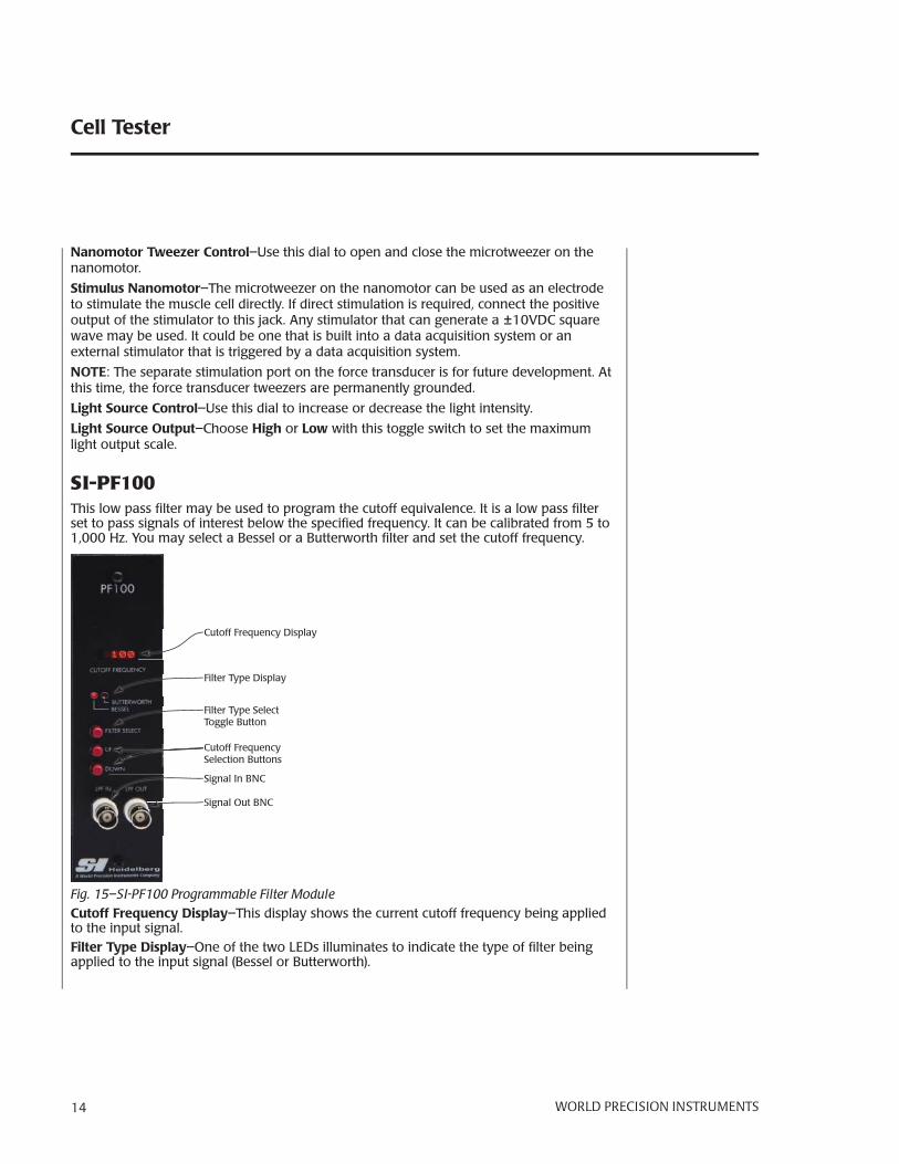
SI-PF100This low pass fi lter may be used to program the cutoff equivalence. It is a low pass fi lter set to pass signals of interest below the specifi ed frequency. It can be calibrated from 5 to 1,000 Hz. You may select a Bessel or a Butterworth fi lter and set the cutoff frequency.
Cutoff Frequency DisplayCC
Filter Type DisplayFF
Filter Type Select Toggle ButtonFFT
Signal In BNCSSS
Signal Out BNCSSSSSS
Cutoff FrequencySelection ButtonsSCSCCCS
Fig. 15–SI-PF100 Programmable Filter ModuleCutoff Frequency Display–This display shows the current cutoff frequency being applied to the input signal.Filter Type Display–One of the two LEDs illuminates to indicate the type of fi lter being applied to the input signal (Bessel or Butterworth).

SI-CTS200
WORLD PRECISION IN STRU MENTS 15
Filter Type Select Toggle Button–Press this button to change the fi lter type. Choices include Bessel and Butterworth. The Filter Type Display LED illuminates to indicate which fi lter type is selected.Cutoff Frequency Selection Buttons–Use the Up and Down buttons to change the frequency of the fi lter applied to the input signal.Signal In BNC– The output signal from the transducer amplifi er comes into the SI-PF100 through this port (LPF IN). If the signal is not routed along the backplane, connect the SI-BAM21-LCB Force Output to this port.Signal Out BNC– The Programmable Filter applies the selected cutoff frequency to the input signal (LPF IN) and makes the fi ltered signal available through this BNC port (LPF OUT).
SI-AOSUBEvery force transducer has a resonance frequency at which it vibrates. The SI-AOSUB allows you to locate that frequency and fi lter the signal to mitigate the noise of the resonance frequency. Since each force transducer is unique, the anti-oscillation unit must be calibrated for each force transducer. Likewise, the tissue mounting hardware affects the resonance frequency. Therefore, the system must be calibrated with the mounting hardware attached to the force transducer.
Front Panel
Pulser Amplitude Adjustment Knob
Pulser Port
External Input Port
Anti-Oscillation FrequencyAdjustment Potentiometer
Signal AmplitudeLED Array
Filtered Signal Output Port
Fig. 16–SI-AOSUB Anti-Oscillation Module

Cell Tester
16 WORLD PRECISION IN STRU MENTS
Pulser Port–Connect the Pulser cable to this port when you need to calibrate the system for a force transducer. The force transducer fi ts inside the Pulser, and the Pulser uses a strong magnet to exert small square-wave forces on the force transducer.
Pulser Amplitude Adjustment Knob–When calibrating a force transducer, this knob adjusts the amplitude of the pulser waveform so the display registers on the Signal Amplitude Array.
Signal Amplitude Array–The 10-position LED array indicates the amplitude of the transducer's response to the pulser's excitations. The LED array indicates when the frequency of the square wave is equal to the resonance frequency of the force transducer.
Anti-oscillation Frequency Adjustment potentiometer– Use the included potentiometer adjustment tool (WPI #13661) to rotate the potentiometer until the force transducer resonates. During this procedure, the number of segments in the Signal Amplitude LED array that light up increases as the resonance frequency approaches that of the force transducer.
External Input Port–The output signal from the transducer amplifi er comes into the SI-AOSUB through this port. If the signal is not routed along the backplane, connect the SI-BAM21-LCB Force Output to this port.
NOTE: When the SI-CTS200 electronics are confi gured at the factory for the Cell Tester systems, the signal is routed internally from the SI-BAM21-LCB module to the SI-AOSUB module. The Force Output connection on the front of the SI-BAM21-LCB module also shows the raw unfi ltered signal from the transducer, but it does NOT need to be connected externally.
Filtered Signal Output Port– Connect a data acquisition system like WPI’s Lab-Trax-8/16 to this BNC connector to record the fi ltered voltage output signal voltage. For test purposes, a multi-meter or oscilloscope may be connected using a standard BNC cable (WPI #2851).
SI-TCM2BThe SI-H Temperature Control Unit is designed for use with the SI-H line of muscle physiology research platforms. It maintains the temperature of an SI-H cuvette up to 45ºC. This unit is available in a standalone model and as a module for the Signal Conditioning Amplifi er System backplane.
FeaturesThe SI-TCM2B temperature controller:• Controls two cuvettes simultaneously• Uses digital control to maintain a constant temperature• Has both high and low alarm warnings which can be user defi ned

SI-CTS200
WORLD PRECISION IN STRU MENTS 17
Front Panel
USB Port
ConfigurationButtons
LED Display
CuvetteConnections
Fig. 17–The SI-TCM2B temperature controller can control two cuvettes simultaneously.
LED Display–Upon startup, this display shows the version of the software the SI-TCM2 is running. During normal operations, this display shows the temperature of the cuvette attached to the channel 1 port, channel 2 port or both. During confi guration, this display shows parameters and confi rmation messages.
USB Port–This port can be used to connect to a computer to log the temperature history. In order to communicate with the computer, a terminal emulation program is required. Several third party options are available, including: Hyperterminal, Real Term (realterm.sourceforge.net) or Cool Term (freeware.the-meiers.org).
Confi guration Buttons–The Display button is used to toggle the display between Channel 1 temperature, Channel 2 temperature and both. The Setup button rotates through the array of confi gurable parameters. The Up and Down buttons are used to adjust the parameters.
Cuvette Connections–Use these ports to connect SI-H cuvettes used with the SI-MT and SI-MKB platforms.
Cell Tester
18 WORLD PRECISION IN STRU MENTS
System Setup
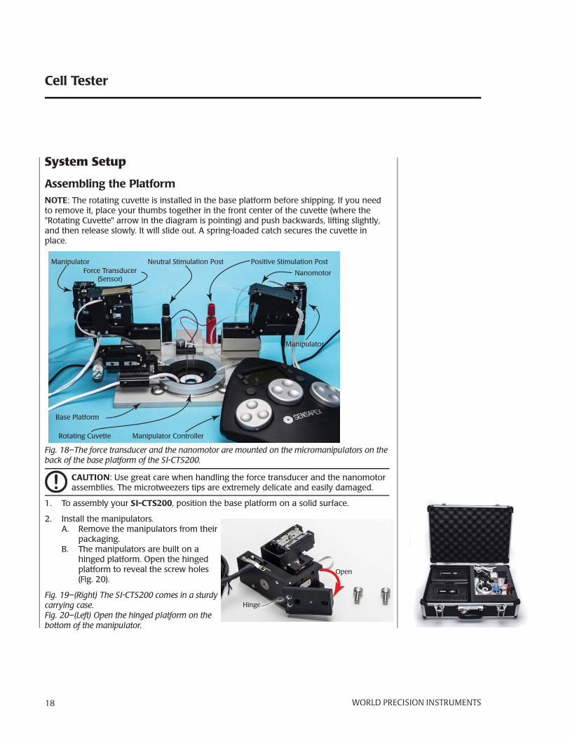
Assembling the PlatformNOTE: The rotating cuvette is installed in the base platform before shipping. If you need to remove it, place your thumbs together in the front center of the cuvette (where the "Rotating Cuvette" arrow in the diagram is pointing) and push backwards, lifting slightly, and then release slowly. It will slide out. A spring-loaded catch secures the cuvette in place.
Force Transducer(Sensor)
Nanomotor
Rotating Cuvette
Positive Stimulation PostNeutral Stimulation Post
Base Platform
Manipulator
Manipulator
Manipulator Controller
Fig. 18– The force transducer and the nanomotor are mounted on the micromanipulators on the back of the base platform of the SI-CTS200.
CAUTION: Use great care when handling the force transducer and the nanomotor assemblies. The microtweezers tips are extremely delicate and easily damaged.
1. To assembly your SI-CTS200, position the base platform on a solid surface.
2. Install the manipulators.A. Remove the manipulators from their
packaging. B. The manipulators are built on a
hinged platform. Open the hinged platform to reveal the screw holes (Fig. 20).
Fig. 19–(Right) The SI-CTS200 comes in a sturdy carrying case.Fig. 20– (Left) Open the hinged platform on the bottom of the manipulator.
Hingegeeeeeeeeeeeee
Open

SI-CTS200
WORLD PRECISION IN STRU MENTS 19
C. Place two M6 screws into the holes on the base of the manipulator and line up the screws with the holes on the base platform manipulator pedestals (Fig. 22). Use a hex wrench and tighten the screws (Fig. 23).
Manipulator Pedestal
Fig. 21–(Left) The base platform has two manipulator pedestals on the back side.Fig. 22– (Center) Line up the screws with the holes in the pedestals.Fig. 23– (Right) Tighten the screws.
Fig. 24– Both manipulators are mounted and tilted back as far as they can go.

Cell Tester
20 WORLD PRECISION IN STRU MENTS
3. Mount the nanomotor to the micromaniplator on the right side of the base platform.
Mount Force Transducer Here Mount Nanomotor Here
Screw holesPositioning Post
Fig. 25–The force transducer must be mounted on the left and the nanomotor on the right side.
CAUTION: To avoid damaging the microtweezers, fl ip the two micromanipulators
all the way back before installing the nanomotor and sensor (Fig. 24).
A. Place the two screws into the screw holes on the nanomotor (Fig. 26).B. There is a small post on the micromanipulator to help position the nanomotor.
Slide the nanomotor over the post and line up the screws with the holes on the micromanipulator.
C. Use a small hex wrench to tighten both screws securely.
Screw holes
Fig. 26– (Left) The screw holes are labeled.Fig. 27–(Right) Secure the nanomotor to the micromanipulator on the right side of the base platform
4. Mount the force transducer to the micromanipulator on the left side of the base platform in the same way that you mounted the nanomotor to the right side micro-manipulator.

SI-CTS200
WORLD PRECISION IN STRU MENTS 21
Fig. 28– The force transducer is mounted on the left side and the nanomotor on the right side.
5. OPTIONAL: if you are using fi eld stimulation, install the platinum electrodes (Fig. 30).
Electrode Holder
Platinum Electrode
Positive Stimulation Post
NeutralStimulation
Post
2mm Banana Jack
PPPP
Fig. 29–When using fi eld stimulation, the platinum electrodes are submerged in the cuvette bath, and the posts are connected with a stimulator.

Cell Tester
22 WORLD PRECISION IN STRU MENTS
A. The electrode holders are connected by wires to the red stimulation post and the black neutral post. Be careful not to bend the electrode. Gently slide it into the electrode holder (Fig. 31).
B. Rotate the electrode in order to position the tip of it in the cuvette bath.C. Connect the positive output of your stimulator to the knob on the red positive
stimulation post using a banana cable. In a similar manner, connect the negative output of your stimulator to the knob on the black neutral stimulation post using a banana cable.
Fig. 30– (Left) The stimulation electrodes are platinum.Fig. 31– (Right) The platinum electrode slides into the electrode holder and reaches into the cuvette.
Fig. 32–The assembled system is ready to be positione on the microscope stage.
6. Place the assembled SI-CTS200 on your inverted microscope.
SI-CTS200
WORLD PRECISION IN STRU MENTS 23
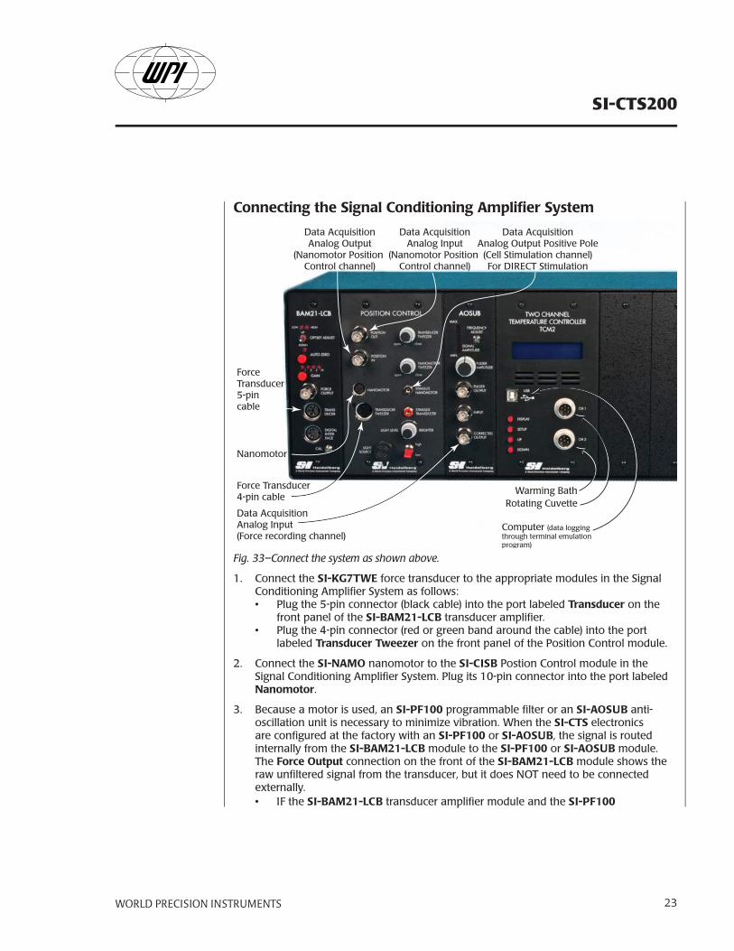
Connecting the Signal Conditioning Amplifi er System
Force Transducer5-pincable
Force Transducer4-pin cable
Nanomotor
Data AcquisitionAnalog Input(Force recording channel)
Data AcquisitionAnalog Output
(Nanomotor Position Control channel)
Data AcquisitionAnalog Input
(Nanomotor Position Control channel)
Data AcquisitionAnalog Output Positive Pole
(Cell Stimulation channel)For DIRECT Stimulation
Rotating Cuvette
Computer (data loggingthrough terminal emulation program)
Warming Bath
Fig. 33–Connect the system as shown above.
1. Connect the SI-KG7TWE force transducer to the appropriate modules in the Signal Conditioning Amplifi er System as follows:• Plug the 5-pin connector (black cable) into the port labeled Transducer on the
front panel of the SI-BAM21-LCB transducer amplifi er.• Plug the 4-pin connector (red or green band around the cable) into the port
labeled Transducer Tweezer on the front panel of the Position Control module.
2. Connect the SI-NAMO nanomotor to the SI-CISB Postion Control module in the Signal Conditioning Amplifi er System. Plug its 10-pin connector into the port labeled Nanomotor.
3. Because a motor is used, an SI-PF100 programmable fi lter or an SI-AOSUB anti-oscillation unit is necessary to minimize vibration. When the SI-CTS electronics are confi gured at the factory with an SI-PF100 or SI-AOSUB, the signal is routed internally from the SI-BAM21-LCB module to the SI-PF100 or SI-AOSUB module. The Force Output connection on the front of the SI-BAM21-LCB module shows the raw unfi ltered signal from the transducer, but it does NOT need to be connected externally. • IF the SI-BAM21-LCB transducer amplifi er module and the SI-PF100

Cell Tester
24 WORLD PRECISION IN STRU MENTS
programmable fi lter module (or SI-AOSUB anti-oscillation module) are not connected to each other through the backplane of the Signal Conditioning Amplifi er System, these two modules must be connected through ports on the front panels of the modules. Use a BNC-BNC cable to connect the Force Output port on the front panel of the SI-BAM21-LCB module to the Signal In (LPF IN) port on the front panel of the SI-PF100 module (or to the Input port on the front panel of the SI-AOSUB module).
• If an SI-PF100 is used because the system has a motor, it can fi lter the low frequencies from the input signal. Use a BNC cable to connect the Signal Out port (LPF OUT) on the front panel of the SI-PF100 module to the analog input of the data acquisition system, which is designated as the force recording channel.
• If an SI-AOSUB is being used instead of a SI-PF100, then use a BNC cable to connect the Corrected Output port of the SI-AOSUB module to the analog input of the data acquisition system, which is designated as the force recording channel. The Corrected Output is the signal from the transducer amplifi er that exists after the resonance frequency of the transducer was removed from the raw transducer signal by the anti-oscillation fi lter.
For information on using the SI-PF100, see "Using the Programmable Filter" on page 29 or on using the SI-AOSUB, see "Using the Anti-Oscillation Unit" on page 29.
4. Using a BNC cable, connect the Corrected Output port of the SI-AOSUB module to the analog input of the data acquisition system, which is designated as the force recording channel. The Corrected Output is the signal from the transducer amplifi er that exists after the resonance frequency of the transducer was removed from the raw transducer signal by the anti-oscillation fi lter.
5. Using a BNC cable, connect the analog output of the data acquisition system, which is designated as the nanomotor position controller channel, to the Position In port on the front panel of the SI-CISB Position Control module.
6. Connect the Position Out port on the SI-CISB module to a second analog input of the data acquisition system, which is designated as the nanomotor position channel.
7. Contraction of the cell in the tester can be triggered by either of two methods of stimulation:• DIRECT stimulation is through the microtweezers holding the ends of the cell
being tested. Using the appropriate cable, connect the positive pole of the analog output of the data acquisition system, which is designated as the cell stimulator channel, to the jack that is labeled Stimulus Nanomotor.
• FIELD stimulation is through the stimulus electrodes attached to the nanomotor and transducer assemblies. The tips of these electrodes are placed in the perfusion buffer near the cell being tested. Using the appropriate cable, connect the positive pole of the analog output of the data acquisition system, which is designated as the cell stimulator channel, to the knob on top of the red Positive Stimulation Post on the Cell Tester platform. In a similar manner connect the negative pole of the same analog output to the knob on top of the black Neutral Stimulation Post on the Cell Tester platform.

SI-CTS200
WORLD PRECISION IN STRU MENTS 25
8. If cuvette temperature control is required, connect the SI-TCM2B as follows:• Line up the rotating cuvette connector with the CH1 or CH2 port on the SI-
TCM2B, press it into place and screw the outer ring of the connector to secure the connector. A second SIH cuvette may be connected to the other port for a warming bath, if desired.
• To monitor the temperature over time, use a USB cable to connect a computer's terminal emulation program using the USB port on the SI-TCM2B.
For information on using the SI-TCM2B, see "Using the Temperature Control Module" on page 31.
9. Verify that the Power switches on the back panel and on the front panel of the Signal Conditioning Amplifi er System are in the on (I) position.

Cell Tester
26 WORLD PRECISION IN STRU MENTS
OPERATING INSTRUCTIONS
Turning the System OnFor convenience, the Signal Conditioning Amplifi er System has two power switches, and both must be on to power the system. One is located on the back panel, and one is on the front. Both switches must be on to power the system. Verify that the power cord is properly installed and plugged into an AC power outlet. All the modules power on/off simultaneously. When the system is setup, just leave the back power switch in the on (I) position.
Using the SI-BAM21-LCB
Calibrating the SI-BAM21-LCB Before taking measurements, the SI-BAM21-LCB must be calibrated. The SI-KG7TWE force transducer responds linearly within its measurement range. Consequently,The SI-BAM21-LCB can be calibrated using only two reference points.
NOTE: Before calibrating the SI-KG transducer or setting its anti-oscillation frequency with an SI-AOSUB module, position the tissue mount being used on the actuator rod of the transducer. During the calibration, place the weight on the tissue mount at the same position where the tissue will be attached.
The basic procedure for calibrating the SI-BAM21-LC involves:
1. Setting a zero reference point with the force transducer un-loaded.
2. Applying a load with a known mass to the tissue mount on the transducer.
3. Choosing one of the two calibration methods to best serve the application. Use the Gain Calibration Potentiometer to adjust the amplifi er’s output range to:• Maximize the resolution for the intended measurement range. For the greatest
precision, maximize the resolution of the SI-BAM21-LCB by calibrating the 10.0V output of the amplifi er to 10-20% above the maximum expected force. For example, if the maximum expected value is 9.0mg, set the SI-BAM21-LCB so that a 10mg mass yields a 10.0V output. The maximum expected output would then be 9.0V, with a 9.0mg applied load.
• Numerically correlate the force with a voltage output. For quick visualization, you may choose to establish a numerical correlation by calibrating the SI-BAM21-LCB so that a force like 5.0g generates a 5.0V output.
NOTE: The following procedure is specifi cally designed for calibrating the SI-BAM21-LCB transducer amplifi er module with an SI-KG7TWE force transducer.
1. Connect the force transducer, the modules in the amplifi cation system and the data acquisition system. See "System Setup" on page 18.
2. Set the Gain switch on the front panel of the SI-BAM21-LCB to X1.

SI-CTS200
WORLD PRECISION IN STRU MENTS 27
3. With no weight suspended from the transducer, press and release the Zero button on the SI-BAM21-LCB. Use the data acquisition system to monitor the transducer signal from the Corrected Output on the SI-AOSUB module. You should see a reading of 0.0VDC ±50mV. Remember that the zeroing error is larger with higher gains. The Offset Adjustment switch needs to be used if a smaller error is desired.
NOTE: When the Zero button is pressed, the zeroing LED illuminates to indicate that the zeroing function is processing.
4. Use the Offset Adjustment switch to adjust the baseline to zero. Press and hold the toggle switch up if you want to raise the baseline. Or, press and hold the toggle switch down to lower the baseline. If the baseline is more than 0.3V above zero, the High LED illuminates, and if it is less than –0.3V, the Low LED illuminates. When the baseline is within 0.3V of zero, the LEDs are off.
NOTE: Once the baseline is zeroed to the desired position, do not touch the Offset Adjustment switch until the calibration procedure is completed.
5. From the point on the tissue mount of the transducer where the tissue will be at-tached, suspend a 5mg weight. Using a 5mg weight allows the transducer to be calibrated to a range that is useful for recording single cell contractions. (Fig. 34).
NOTE: Mass in grams can be converted to force in Newtons (N) by multiplying the weight hung on the transducer by gravitational acceleration. Since force equals mass times acceleration (F = ma), a 5mg weight is equal to 49uN (0.000005kg * 9.8m/s2 = 0.000049N). Make sure that the mass used to calibrate the transducer amplifi er creates a force that falls within the operating range of the force transducer and amplifi cation factor you selected.
Fig. 34– Suspend a 5mg weight from the end of the force transducer.
6. After the suspended mass (5mg) becomes motionless, use the data acquisition system to monitor the Corrected Output from the SI-AOSUB module while adjusting the Gain Calibration potentiometer on the SI-BAM21-LCB. Use a potentiometer adjust-ment tool to adjust the Gain Calibration potentiometer to a value of 5.0V, so that each 1mg defl ection is equal to 1.0V.
NOTE: This procedure is adequate if the force acts perpendicular to the tissue mount on the transducer pin. If the force is not perpendicular to the tissue mount, the output signal has to be adjusted correspondingly.

Cell Tester
28 WORLD PRECISION IN STRU MENTS
Realigning the Nanomotor Mechanical Zero Position Like other components in the Cell Tester system, the SI-NAMO nanomotor is calibrated at the factory. This includes setting the mechanical zero (center) position of the actuator. After extensive use, the zero position of the actuator may shift slightly. The shift is identifi ed when the travel of the actuator is restricted more in one direction than the other. You can reset the mechanical zero position of the nanomotor as follows:
1. Connect the SI-NAMO nanomotor to the Cell Tester Signal Amplifi cation system by plugging the 10-pin connector of the nanomotor into Nanomotor port on the front panel of the Position Control module. Turn the amplifi er system on.
2. Connect the analog output of the data acquisition system, which is designated for controlling motor movement, to the Position In port of the Position Control module.
3. Connect the analog input of the data acquisition system, which is designated for recording motor position, to the Position Out port of the Position Control module.
4. Program the data acquisition system so that the signal that controls the position of the nanomotor is 0.0V and constant. Normally, the actuator of the nanomotor is centered at this voltage. Program the channel, which is used to record the nanomotor position, to a range of +10V.
5. Start the data recording software to:• Send the 0.0V positioning signal to the nanomotor through the Position In port• Record the nanomotor position signal from the Position Out port.
6. If the voltage being recorded on the nanomotor position (Position Out) channel is not 0.0V, use the small hex wrench to turn the recessed adjustment screw on the back of nanomotor (Fig. 35) until the voltage on that channel is zero. When the voltage on the Position Out channel is zero, the actuator of the nanomotor is centered and the device is ready to use.
Adjustment Screwmenmenmenene t St crewenenennt Screw
Fig. 35–The adjustment screw is on the back of the nanomotor.
Making MeasurementsAfter the SI-BAM21-LCB has been calibrated, measurements may be taken.
1. Turn the Signal Conditioning Amplifi er System Power switch on (I). The system needs to be powered on for 30 minutes before calibration. Leave it on while your prepare to take measurements.

SI-CTS200
WORLD PRECISION IN STRU MENTS 29
2. Turn on the data acquisition system.
3. Press the Zero button to set the baseline value for the measurements.
NOTE: When the Zero button is pressed, the zeroing LED illuminates to indicate that it is functioning properly.
4. Measurements may be taken.
Setting System Gain FactorTThe SI-BAM21-LCB gain multiplier setting is selected with an internal jumper that is confi gured at the factory for use with the muscle tester system of your choice (SI-MT, SI-MKB, SI-HTB). The X1 setting (SI-MT/SI-HTB) allows for 1X, 2X, 5X and 10X gains. The X10 setting (SI-MKB, SI-CTS200) allows for 10X, 20X, 50X and 100X gains that may be needed when recording passive tension or small force transients from single cells.
1. Turn off the Signal Conditioning Amplifi er System and unplug it from the power outlet.
2. Remove the two screws on the face of the SI-BAM21-LCB module.
3. Gently slide the module out of the Signal Conditioning Amplifi er System frame.
4. Locate the 3-pin jumper J16. Jumper pins 1 and 2 to use the SI-BAM21-LCB with the X1 gain multiplier, or jumper pins 2 and 3 for use with the X10 gain multiplier.
5. Reinstall the module into the frame and secure it with the screws.
Using the Programmable Filter1. Press the Filter Select button to choose the type of fi lter you would like to apply. The
appropriate Filter Type Display LED illuminates (Bessel or Butterworth).
2. Use the Up or Down (Cutoff Frequency Selection) buttons to set the desired cutoff frequency. The frequency is shown on the Cutoff Frequency Display. When using a Bessel fi lter, do not apply a cutoff frequency greater than 1kHz. Choose the cutoff frequency carefully. You want to eliminate the resonance frequency without affect-ing the signal of interest. When you set your cutoff frequency, consider the typical resonance frequency of your transducer.
Force Transducer SI-KG2 SI-KG4 SI-KG4A SI-KG7 SI-KG7A SI-KG7B SI-KG20Resonance Frequency 1.3kHz 1.2kHz 1.2kHz 250Hz 500Hz 550Hz 590Hz
Using the Anti-Oscillation Unit
Adjusting the Anti-Oscillation FilterThe anti-oscillation fi lter is adjusted at the factory using the transducer that is supplied with the Cell Tester system. Normally, the fi lter does not need to be reset, unless a different force transducer is connected to the unit. To adjust the anti-oscillation fi lter properly, the transducer is excited at its resonance frequency using a magnetic driver or pulser (WPI #97204).

Cell Tester
30 WORLD PRECISION IN STRU MENTS
Fig. 36–(Left) This pulser assembly has no force transducer mounted in it.Fig. 37– (Right) A force transducer is mounted in the SI-AOSUB pulser assembly.
Keep in mind that:• The closer the anti-oscillation frequency matches the resonance frequency of the
force transducer, the more the ringing phenomenon is removed from the force signal.
• The resonance frequency can be evoked at anti-oscillation frequencies that are multiples of the resonance frequency. For example, if the resonance frequency of the transducer is 200Hz, it can also be evoked when the anti-oscillation frequency is set to 400 or 600Hz. The anti-oscillation fi lter works best when the anti-oscillation frequency is set at the actual resonance frequency of the transducer.
1. Slide the force transducer, with its microtweezer or glass fi ber mount in position, forward into the pulser ( magnetic driver assembly) until it rests against the stop at the front of the pulser. See Fig. 37.
2. Attach the cable of the pulser to BNC connector of the Pulser Output on the front of the Anti-Oscillation module (SI-AOSUB).
3. Using the potentiometer adjustment tool provided with the signal conditioning amplifi er system, rotate the calibration screw of the Anti-oscillation Frequency Adjustment potentiometer completely to the left (counter-clockwise). The anti-oscillation frequency is now set to the lowest possible level.
4. Turn the Pulser Amplitude Adjustment knob completely to the left (counter-clock-wise). The amplitude of the anti-oscillation frequency is now set to the lowest pos-sible level. Then, slowly turn the Pulse Amplitude Adjustment knob to the right until a couple of bars on the Signal Amplitude LED array are illuminated.
5. Using the potentiometer adjustment tool, slowly turn the calibration screw of the Anti-oscillation Frequency Adjustment potentiometer to the right (clockwise) while observing the Signal Amplitude LED array. As the calibration screw is turned to the right, the anti-oscillation frequency gets closer to the resonance frequency of the transducer, and the transducer begins to oscillate at higher amplitude as indicated by the increased number of lights in the LED array that illuminate.
6. Continue to rotate the calibration screw of the Anti-oscillation Frequency

SI-CTS200
WORLD PRECISION IN STRU MENTS 31
Adjustment potentiometer to the right (clockwise) until the greatest number of bars on the Signal Amplitude LED array are illuminated.
If the Signal Amplitude LED array becomes fully illuminated as the anti-oscillation frequency is increased, decrease the pulse amplitude by turning its control knob to the left (counterclockwise). Turn the knob to the left until some of the bars at the top of the Signal Amplitude LED array are no longer illuminated.
7. Repeat Step 6 until the greatest number of bars on the Signal Amplitude LED array is illuminated without the signal amplitude being saturated. When this occurs, the anti-oscillation frequency has been set equal to the resonance frequency of the trans-ducer.
NOTE: If the Signal Amplitude LED array is saturated at any time during the frequency calibration, reduce the pulse amplitude by rotating Pulser Amplitude Adjustment knob to the left until some of the bars at the top of the array are no longer illuminated.
Fig. 38–The upper trace is a force transient obtained directly from the bridge amplifi er output, and the lower trace shows the signal after it passes through the “anti oscillation” unit.
Using the Temperature Control Module
Understanding the Display The default display is two lines and shows the temperature of both channels. If you prefer, you may display information from a single channel, either Channel 1 or Channel 2.
CH 1 = 36.9ºC OK CH2 = 37.0ºC OK
Channel 1 InformationChannel 2 Information
Live Temperature Readout
Alarm State
Heating/Cooling Indicator
Fig. 39–Two Channel display mode provides live data on both channels.
Cell Tester
32 WORLD PRECISION IN STRU MENTS
CH 1 Temp 36.9ºC ** OK **
Channel 1 Information Live Temperature Readout
Alarm State Heating Indicator
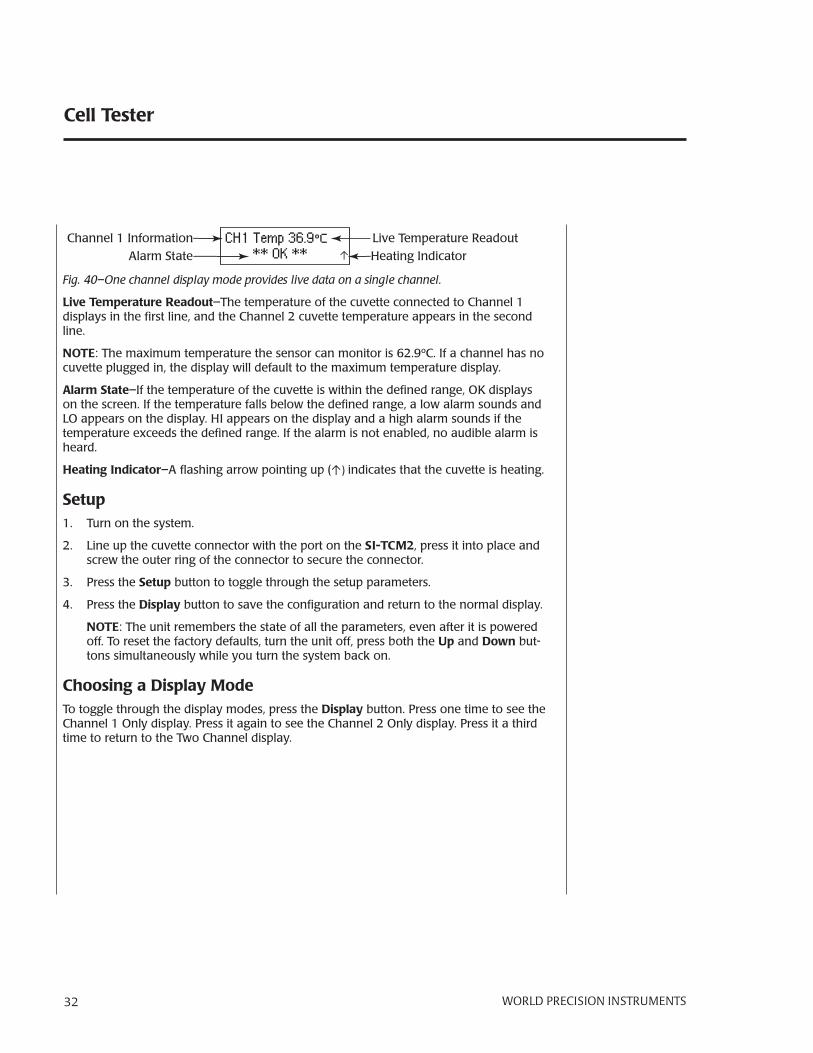
Fig. 40–One channel display mode provides live data on a single channel.
Live Temperature Readout–The temperature of the cuvette connected to Channel 1 displays in the fi rst line, and the Channel 2 cuvette temperature appears in the second line.
NOTE: The maximum temperature the sensor can monitor is 62.9ºC. If a channel has no cuvette plugged in, the display will default to the maximum temperature display.
Alarm State–If the temperature of the cuvette is within the defi ned range, OK displays on the screen. If the temperature falls below the defi ned range, a low alarm sounds and LO appears on the display. HI appears on the display and a high alarm sounds if the temperature exceeds the defi ned range. If the alarm is not enabled, no audible alarm is heard.
Heating Indicator–A fl ashing arrow pointing up (↑) indicates that the cuvette is heating.
Setup1. Turn on the system.
2. Line up the cuvette connector with the port on the SI-TCM2, press it into place and screw the outer ring of the connector to secure the connector.
3. Press the Setup button to toggle through the setup parameters.
4. Press the Display button to save the confi guration and return to the normal display.
NOTE: The unit remembers the state of all the parameters, even after it is powered off. To reset the factory defaults, turn the unit off, press both the Up and Down but-tons simultaneously while you turn the system back on.
Choosing a Display ModeTo toggle through the display modes, press the Display button. Press one time to see the Channel 1 Only display. Press it again to see the Channel 2 Only display. Press it a third time to return to the Two Channel display.

SI-CTS200
WORLD PRECISION IN STRU MENTS 33
Setup MenuPress the Setup button to toggle through the Setup menu and cycle through the list of available parameters. Parameters are shown in Fig. 41.
Channel 1 SetpointCH1 Setpoint
CH2 High Alarm SetpointCH2 High Alarm
CH2 Low Alarm SetpointCH2 Low Alarm
Channel 2 SetpointCH2 Setpoint
BacklightBacklight Level
CH 1 Low Alarm SetpointCH1 Low Alarm
CH 1 Alarm EnableCH1 Alarm
CH 1 High Alarm SetpointCH1 High Alarm
CH 2 Alarm EnableCH2 Alarm
Fig. 41– The Setup button lets you toggle through the list of parameters.
Adjusting the Setpoint1. Press the Setup button. The Channel 1 setpoint displays. To modify the Channel 2
setpoint, press the Setup button until “CH2 Setpoint” displays.
CH 1 Setpoint 37.0ºC
Fig. 42–Press the Up and Down buttons to adjust the Channel 1 Setpoint.
2. Press the Up or Down button to adjust the setpoint. The maximum setpoint allowed is 45ºC.
3. Press the Display button to save the confi guration and return to the normal display.
Setting AlarmsBoth Channel 1 and Channel 2 have high and low alarm values. By default, the low alarms are set at 36ºF, the high alarms are set at 38ºF and the alarms are disabled.
1. Press the Setup button:• Twice to display the Channel 1 High Alarm• Three times to display the Channel 1 Low Alarm• Five times to display the Channel 2 High Alarm• Six times to display the Channel 2 Low Alarm

Cell Tester
34 WORLD PRECISION IN STRU MENTS
The alarm setting displays.
CH 1 High Alarm 38.0ºC
Fig. 43–Press the Up and Down buttons to adjust the alarm setting.
2. Press the Up or Down button to adjust the alarm setting.
3. Press the Display button to save the confi guration and return to the normal display.
Changing the Backlight Level for the DisplayBy default the backlight level is set at 4. To make the display brighter, increase the level up to a maximum of 8. To dim the display, choose a lower level.
1. Press the Setup button until “Backlight Level” appears on the screen.
Backlight LevelMin=1 4 Max=8
Fig. 44–Press the Up or Down buttons to adjust the backlight level.
2. Press the Up or Down button to adjust the backlight level.
3. Press the Display button to save the confi guration and return to the normal display.
Enabling/Disabling the AlarmsBy default the alarms are disabled. When enabled, the unit will emit a beep when an alarm state occurs.
1. Press the Setup button until “CH1 Alarm” or “CH2 Alarm” appears on the screen.
CH1 Alarm DISABLED
Fig. 45–By default the alarms are disabled.
2. Press the Up or Down button to enable or disable the alarm.
3. Press the Display button to save the confi guration and return to the normal display.
Using the USB Port OutputThe USB port can be used to connect to a computer to log the temperature history. In order to communicate with the computer, a terminal emulation program is required. Several third party options are available, including: Hyperterminal, Real Term (realterm.sourceforge.net) or Cool Term (freeware.the-meiers.org).

SI-CTS200
WORLD PRECISION IN STRU MENTS 35
1. When you use a standard USB cable to connect the SI-TCM2 to your computer, the computer will automatically install the necessary drivers.
2. Set up your terminal emulation program using the following parameters:• Baud rate: 38400 Bd• Data: 8 bits, (1 start, 1 stop)• Parity: None
3. The comma delimited, output fi le logs the temperature 10 times a second.
Holding Cells with MicrotweezersNOTE: Additional information about MyoTakTM biocoampatible cellular adhesive and its usage is available in the MyoTak manual available at www.wpiinc.com.
CAUTION: Even though microtweezers are used to manipulate and hold single cells, the cells are not held by the clamping pressure of the tweezers. Cells are held to the tips of the tweezers by bonding with the MyoTak coating on the tweezers. If
excessive pressure is exerted on the cell's membrane, the cell will burst.
1. Before placing buffer and cells in the cuvette used during the experiment, coat the bottom of the cuvette with a thin layer of a 100µM BSA ( Bovine Serum Albumin) solu-tion.• Apply the coating by placing a large drop of the BSA solution on the bottom of
the cuvette and spreading it with the edge of a microscope slide or cover slip.• Tilt the cuvette dish or its bottom to allow excess BSA solution to drip off. Allow
the BSA coating to dry before using the cuvette.• The BSA layer prevents the cells from sticking to the bottom of the cuvette and
improves the fl ow of buffer in the cuvette.
2. Place the buffer containing the isolated cells in the cuvette, and place the cuvette on the stage of microscope.
3. Immerse the coated microtweezers in the buffer contained in the cuvette as soon as possible to prevent the dehydration of the MyoTak glue.
NOTE: For directions on coating the microtweezers with MyoTak, see the MyoTak manual available at www.wpiinc.com.
4. While viewing the cell suspension with a 10X objective, locate a cell and move the stage to position the cell in the center of the fi eld of view. Position a set of tweezers near each end of the cell.
5. While viewing a cell with a 40X objective, position one of the pairs of open tweezers around the end of the cell. Bring the surface of the MyoTak layer that is between the tweezers into focus. Gently close the tips of the tweezers until the MyoTak layer de-presses the cell membrane only a fraction of a micron. After being gently pressed into the cell membrane, the MyoTak glue should bind to the cell, and the tweezers can be opened until the cell membrane is not depressed anymore.
6. Repeat Step 5 on the other end of the cell.

Cell Tester
36 WORLD PRECISION IN STRU MENTS
7. Use the manipulator controls to lift the cell off the bottom of the cuvette without stretching it.
8. Once the cell is off the bottom of the cuvette, test the binding of the cell to the twee-zers. Either stretch the cell a few microns or stimulate the cell to make it contract:
CAUTION: When the cell is stimulated using fi eld stimulating electrodes and a stimulus isolator, the fi rst contraction is usually greater than the subsequent contractions. After the fi rst contraction, the cell enters a steady activation state and
responds with lower force in each subsequent contraction.
• If the cell remains attached to the same section of MyoTak, the bond between the cell and the glue is strong enough to continue the experiment.
• If the cell slides across the MyoTak layer, close the tweezers another fraction of a micron around the end of the cell in an attempt to secure a tighter bond.
• If the cell still slides across the MyoTak layer, the MyoTak coating was either too thick or not completely dried. The Myotak must be removed from the tweezers, and the tweezers need to be re-coated.
• If the cell falls off the MyoTak layer after being pressed into the glue, the MyoTak layer was dried too long and did not rehydrate properly. The MyoTak must be removed from the tweezers, and the tweezers need to be re-coated.
• After re-coating, test the binding of the cell and MyoTak again before beginning the experiment.
Attaching Cells to Glass Microrods1. Before placing buffer and cells in the cuvette used during the experiment, coat the
bottom of the cuvette with a thin layer of a 100µM BSA ( Bovine Serum Albumin) solu-tion.• Apply the coating by placing a large drop of the BSA solution on the bottom of
the cuvette and spreading it with the edge of a microscope slide or cover slip.• Tilt the cuvette dish or its bottom to allow excess BSA solution to drip off. Allow
the BSA coating to dry before using the cuvette.• The BSA layer prevents the cells from sticking to the bottom of the cuvette and
improves the fl ow of buffer in the cuvette.
2. Place the buffer containing the isolated cells in the cuvette, and place the cuvette on the stage of microscope.
3. Immerse the coated microrods in the buffer contained in the cuvette as soon as pos-sible to prevent the dehydration of the MyoTak glue.
4. While viewing the cell suspension with a 10X objective, locate a cell and move the stage to position the cell in the center of the fi eld of view. Position one of the micro-rods over each end of the cell. The rods should be perpendicular to the long axis of the cell, which means that the rods are also across the axis of the force and stretch of the cell.
5. Lower one of the glass microrods onto the surface of the cell near its end. Lower the rod until the surface of the cell conforms to the shape of the microrod.
6. Repeat Step 5 on the other end of the cell.
SI-CTS200
WORLD PRECISION IN STRU MENTS 37
7. Use the manipulator controls to lift the cell off the bottom of the cuvette without stretching it.
8. Once the cell is off the bottom of the cuvette, test the binding of the cell to the micro-rods. Either stretch the cell a few microns or stimulate the cell to make it contract:
CAUTION: When the cell is stimulated using fi eld stimulating electrodes and a stimulus isolator, the fi rst contraction is usually greater than the subsequent contractions. After the fi rst contraction, the cell enters a steady activation state and
responds with lower force in each subsequent contraction.
• If the cell remains attached to the same section of MyoTak, the bond between the cell and the glue is strong enough to continue the experiment.
• If the cell slides across the MyoTak layer, lower the cell to the bottom of the cell and push the rods onto the surface of the cell again.
• If the cell still slides across the surface of the MyoTak, the layer of MyoTak was either too thick or not completely dried. The glass microrod must be removed from its support and replaced with a new microrod that needs to be re-coated.
• If the cell falls off the MyoTak layer after being pressed into the glue, the MyoTak layer was dried too long and did not rehydrate properly. The glass microrod must be removed from its support and replaced with a new microrod that needs to be recoated.
• After recoating, test the binding of the cell and MyoTak again before beginning the experiment.
MAINTENANCE
The Signal Conditioning Amplifi er System is maintenance free. However, to protect it, follow these guidelines:
• Place the Signal Conditioning Amplifi er System in a clean, dry location.• Keep liquids away from the Signal Conditioning Amplifi er System connections.

Cell Tester
38 WORLD PRECISION IN STRU MENTS
ACCESSORIES
SI-BAM21-LCB AccessoriesPart Number Description13661 Potentiometer Adjustment Tool ( Tweaker)2851 BNC CableSI-DAS SI-H Data Acquisition/Analysis SystemSI-KG2 0-2N Force TransducerSI-KG2B 0-0.5N Force TransducerSI-KG4 0-50mN Force TransducerSI-KG4A 0-20mN Force TransducerSI-KG7 0-5mN Force TransducerSI-KG7A 0-5mN Force TransducerSI-KG7B 0-10mN Force TransducerLAB-TRAX-8/16 8-Channel Data Acquisition SystemSI-MT-L Muscle Tester with long cuvetteSI-MT-S Muscle Tester with short cuvetteSI-MT-O Muscle Tester with optical cuvetteSI-FS Electrode for fi eld stimulation
Position Controller AccessoriesPart Number Description2851 BNC CableSI-DAS SI-H Data Acquisition/Analysis SystemLAB-TRAX-8/16 8-Channel Data Acquisition System
SI-AOSUB AccessoriesPart Number Description13661 Potentiometer Adjustment Tool ( Tweaker)2851 BNC Cable97204 Pulser – SI-AOSUB Calibration UnitLAB-TRAX-8/16 8-Channel Data Acquisition System
SI-TCM2B AccessoriesPart Number Description801513 Universal Input Power Supply AC Adapter (12V DC at
3.75A 50/60Hz, 2.5mm ID/5.5mm OD with positive center DC barrel (Standalone SI-TCM2 only)
801514 Power Cord for AC Adapter, US plugLAB-TRAX-8/16 8-Channel Data Acquisition System
SI-CTS200
WORLD PRECISION IN STRU MENTS 39
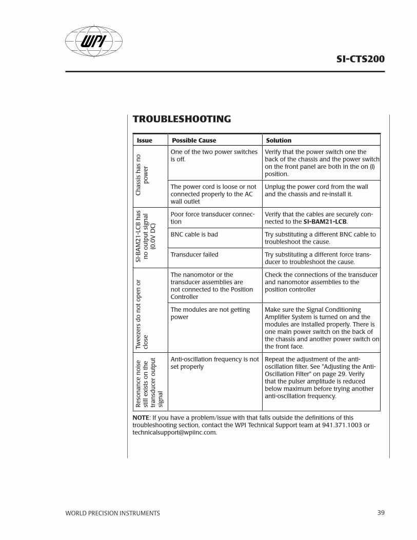
TROUBLESHOOTING
Issue Possible Cause SolutionC
has
sis
has
no
po
wer
One of the two power switches is off.
Verify that the power switch one the back of the chassis and the power switch on the front panel are both in the on (I) position.
The power cord is loose or not connected properly to the AC wall outlet
Unplug the power cord from the wall and the chassis and re-install it.
SI-B
AM
21
-LC
B h
as
no
outp
ut
sign
al
(0.0
V D
C)
Poor force transducer connec-tion
Verify that the cables are securely con-nected to the SI-BAM21-LCB.
BNC cable is bad Try substituting a different BNC cable to troubleshoot the cause.
Transducer failed Try substituting a different force trans-ducer to troubleshoot the cause.
Twee
zers
do
no
t o
pen
or
clo
se
The nanomotor or the transducer assemblies are not connected to the Position Controller
Check the connections of the transducer and nanomotor assemblies to the position controller
The modules are not getting power
Make sure the Signal Conditioning Amplifi er System is turned on and the modules are installed properly. There is one main power switch on the back of the chassis and another power switch on the front face.
Res
on
ance
no
ise
still
exi
sts
on
th
e tr
ansd
uce
r o
utp
ut
sign
al
Anti-oscillation frequency is not set properly
Repeat the adjustment of the anti-oscillation fi lter. See "Adjusting the Anti-Oscillation Filter" on page 29. Verify that the pulser amplitude is reduced below maximum before trying another anti-oscillation frequency.
NOTE: If you have a problem/issue with that falls outside the defi nitions of this troubleshooting section, contact the WPI Technical Support team at 941.371.1003 or [email protected].

Cell Tester
40 WORLD PRECISION IN STRU MENTS
SPECIFICATIONS
This instrument conforms to the following specifi cations:
ChassisMaximum Power Consumption 1.3A at 115V 50/60Hz, 1.8A at 230V 50/60Hz
SI-BAM21-LCB Specifi cationsInput Confi guration Current to voltage converterGain 1X, 2X, 5X, 10X - Switch slectableOutput Impedance 470Power Requirements 12V DC provided by the chassisOutput Range ±10V DC
Position Controller Specifi cationsPower Requirements 12V DC provided by the chassisPosition In Range ±10V, IV = 104µPosition Out Range ±10V, IV = 104µ
SI-AOSUB Specifi cationsPower 12V DC provided by the chassisInput ±10V DC
SI-TCM2B Specifi cationsInput Confi guration Current to voltage converterOperating Temperature Range Room temperatureDisplay Precision 0.1ºCController Resolution 0.1ºCCuvette Temperature Sensor 1000 RTD (1000 at 0ºC)
Power Requirements 12V DC provided by the chassis
SI-KG7TWE Force TransducerRange 0–5mN (0–0.5g)Noise 20nN at 10X gainCompliance 10µm/mNForce Resolution 0.3µNResonance Frequency 250HzTime Resolution 7ms
Resolutions were determined while using the SI-AOSUB anti-oscillation fi lter.
NAMO Nanomotor Specifi cationsTotal Travel ±90µmResolution 20nmSmallest Step 60nmInput ±10V (calibrated at 10µm/V)
97204 Pulser Specifi cationsPulser Output 0–10V DC adjustable 85Hz–1.0KHzDamping Frequency Range 85Hz–1.0KHzOutput Range ±10V
SI-CTS200
WORLD PRECISION IN STRU MENTS 41
INDEX
Aactuator 28adhesive 4alarm 16, 33amplifi cation factor 27amplifi er 10amplitude 16analog input 13, 24, 28analog output 13, 28analog voltage 10anti-oscillation 23, 29anti-oscillation unit 5, 15
Bbacklight level 34backplane 6baseline 10, 11biocompatible adhesive 4BNC 13, 16, 24, 39Bovine Serum Albumin 35, 36BSA 35, 36buffer 10
Ccalibration potentiometer 12corrected output 24cover slip 35cuvette 4, 18
Ddata acquisition 10, 12, 13, 24digital interface 12DIN 12direct stimulation 24
Eelectrode 14
Ffeedback 8fi eld stimulation 21, 24, 36fi lter 15, 29force determinations 6force output 16force transducer 6, 10, 11, 12,
23, 39fuse 6
Ggain 11gain factor 10, 26glass rods 7, 36
Hheart cells 7
LLab-Trax-8/16 16LED 13legacy 12light 12, 13, 14
Mmagnetic driver assembly 30maintenance 37mass 27measurements 28mechanical zero 28micromanipulators 20microrods 36microscope 22microtweezer 13microtweezers 5, 35multi-meter 16myocyte 7MyoTak 4, 7, 35
Nnanomotor 8, 13, 23, 28noise 39
Ooffset adjustment 11, 27optical force transducer
amplifi er 10oscilloscope 16output 12output signal 39
Pparts list 4perturbations 6piezo motor 3platform 18position control 12position controller 5position in 28position out 28power 26, 39power supply 3power switches 6pulser 16, 30pulser assembly 4
Rraw signal 24raw unfi ltered signal 12, 16resonance frequency 5, 15,
16, 30returns 4rotating cuvette 4, 18
Ssaturate 31setpoint 33setup 18SI-AOSUB 3, 15SI-BAM21-LC 10SI-BAM21-LCB 3, 5, 10SI-CTS100A 3SI-CTS100B 3SI-CTS100C 3signal 12, 16, 39SI-KG7TWE 3, 6, 23SI-NAMO 3, 8, 23, 28SI-TCM2 31SI-TCM2B 16skeletal muscle 7square wave 14, 16stimulate 14stimulation 21, 24stimulator 13stimulus nanomotor 24
Ttemperature control 6, 16, 25trace 31trigger 13troubleshoot 38tweaker 38tweezers 12, 35, 39
Uunfi ltered signal 12, 16unpacking 4
Vvibrate 15
Zzero 10, 11, 27, 29zero switch 11, 16

Cell Tester
42 WORLD PRECISION IN STRU MENTS
DECLARATION OF CONFORMITY

SI-CTS200
WORLD PRECISION IN STRU MENTS 43
WARRANTY
WPI (World Precision Instruments, Inc.) warrants to the original pur chas er that this equipment, including its components and parts, shall be free from defects in ma te ri al and workmanship for a period of one year* from the date of receipt. WPI’s obligation under this warranty shall be limited to repair or replacement, at WPI’s option, of the equip ment or defective components or parts upon receipt thereof f.o.b. WPI, Sarasota, Florida U.S.A. Return of a repaired instrument shall be f.o.b. Sarasota.
The above warranty is contingent upon normal usage and does not cover products which have been modifi ed without WPI’s approval or which have been subjected to unusual physical or electrical stress or on which the orig i nal identifi cation marks have been removed or altered. The above warranty will not apply if adjustment, repair or parts replacement is required because of accident, neglect, misuse, failure of electric power, air conditioning, humidity control, or causes other than normal and ordinary usage.
To the extent that any of its equipment is furnished by a manufacturer other than WPI, the fore go ing warranty shall be applicable only to the extent of the warranty furnished by such other manufacturer. This warranty will not apply to appearance terms, such as knobs, handles, dials or the like.
WPI makes no warranty of any kind, express or implied or statutory, including without lim i ta tion any warranties of mer chant abil i ty and/or fi tness for a particular purpose. WPI shall not be liable for any damages, whether direct, indirect, special or con se quen tial arising from a failure of this product to operate in the manner desired by the user. WPI shall not be liable for any damage to data or property that may be caused directly or indirectly by use of this product.
Claims and Returns• Inspect all shipments upon receipt. Missing cartons or obvious damage to cartons should be noted on the delivery receipt before signing. Concealed loss or damage should be reported at once to the carrier and an inspection requested. All claims for shortage or damage must be made within 10 days after receipt of shipment. Claims for lost shipments must be made within 30 days of invoice or other notifi cation of shipment. Please save damaged or pilfered cartons until claim settles. In some instances, photographic documentation may be required. Some items are time sensitive; WPI assumes no extended warranty or any liability for use beyond the date specifi ed on the container.
• WPI cannot be held responsible for items damaged in shipment en route to us. Please enclose merchandise in its original shipping container to avoid damage from handling. We recommend that you insure merchandise when shipping. The customer is responsible for paying shipping expenses including adequate insurance on all items returned.
• Do not return any goods to WPI without obtaining prior approval and instructions (RMA#) from our returns department. Goods returned unauthorized or by collect freight may be refused. The RMA# must be clearly displayed on the outside of the box, or the package will not be accepted. Please contact the RMA department for a request form.
• Goods returned for repair must be reasonably clean and free of hazardous materials.
• A handling fee is charged for goods returned for exchange or credit. This fee may add up to 25% of the sale price depending on the condition of the item. Goods ordered in error are also subject to the handling fee.
• Equipment which was built as a special order cannot be returned.
• Always refer to the RMA# when contacting WPI to obtain a status of your returned item.
• For any other issues regarding a claim or return, please contact the RMA department
Warning: This equipment is not designed or intended for use on humans.
* Electrodes, batteries and other consumable parts are warranted for 30 days only from the date on which the customer receives these items.
World Precision Instruments, Inc.International Trade Center, 175 Sarasota Center Blvd., Sarasota FL 34240-9258Tel: 941-371-1003 • Fax: 941-377-5428 • E-mail: [email protected]: 1 Hunting Gate, Hitchin, Hertfordshire SG4 0TJ • Tel: 44 (0) 1462 424700 • Fax: 44 (0) 1462 424701 • E-mail: [email protected]: Zossener Str. 55, 10961 Berlin • Tel: 030-6188845 • Fax: 030-6188670 • E-mail: [email protected] & Hong Kong: Rm 20a, No8 Dong Fang Rd., Lu Jia Zui Financial District, shanghaai PRC • Tel: +86 688 85517 • E-mail: [email protected]