Embed Size (px)
Citation preview
MCT242: Electronic Instrumentation
Lecture 4:
Signal Conditioning
Faculty of EngineeringFaculty of EngineeringFaculty of EngineeringFaculty of Engineering

Transducer
Bridge
CompletionAmplification
Low Pass
Filter
Sample
and
Hold
Excitation
Analog
To
Digital
Converter
Multiplexing
and
data
transmission
End To End Data Acquisition
Signal Conditioner
Data Acquisition Unit
Last Week -
Sensors
This Week
Week –
Signal
Conditioning
Recording,
Storage
and DisplayNext week from
today – D/A and
A/D Conversion Two Weeks From
Today -
Communication
Overview
• Signal Conditioning – Overview
• Grounding and Input Types
• Isolation

Typical Roles of Signal Conditioning
• Signal Conditioning
– Provides external excitation and grounding
– Completes the circuit (bridges)
– Linearizes
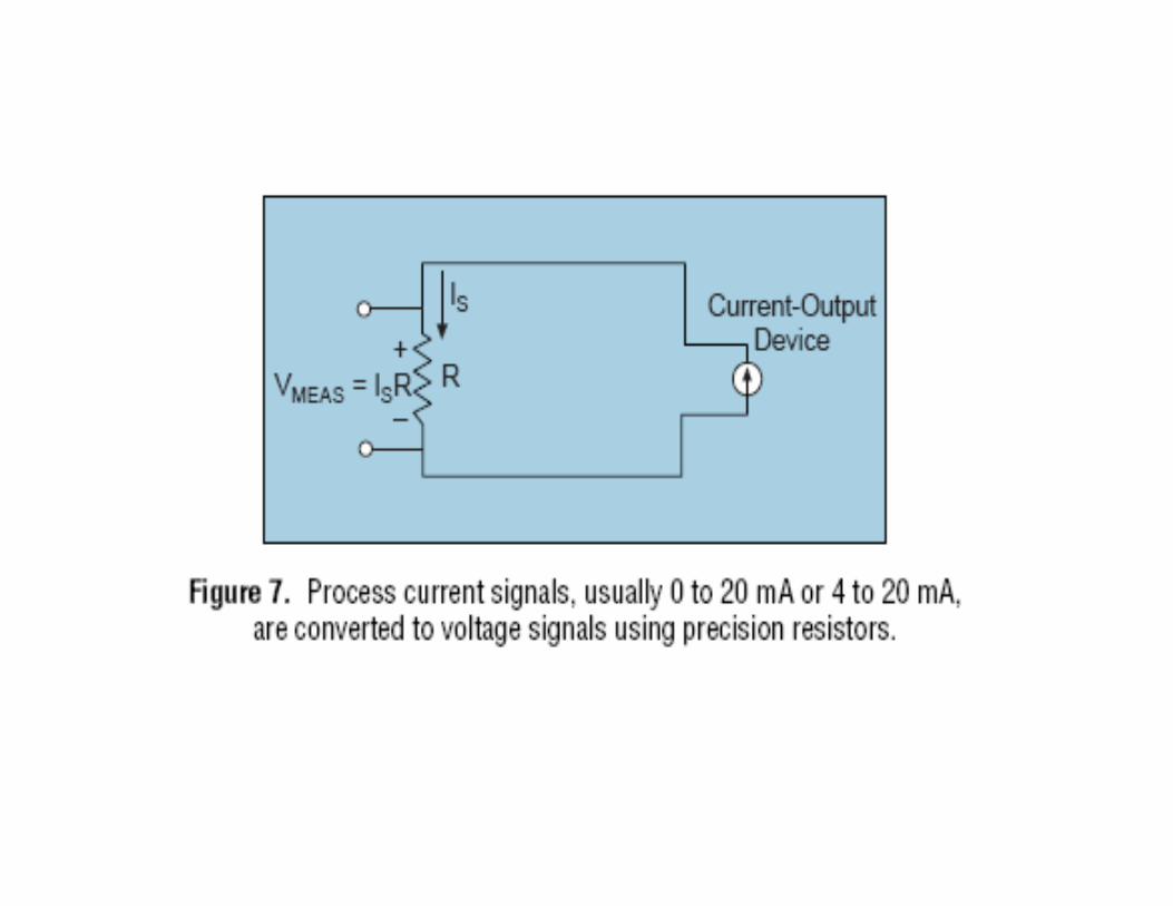
– Filters (typically low pass filter which only allows low frequency signals through)
– Amplifies
– Isolates one part of a system electrically from other parts of the system
– Typical input is in millivolts, output is in volts


Floating Versus Ground References• Voltage is a measurement of the difference in electrical potential between
two points• As such, voltage measurements must always be referenced to a known
level • Traditionally voltage measurements are made with respect to earth ground
– A spike drilled into the ground provides a reference to the lowest potential, literally the “earth ground”
• In self generating voltage systems, like batteries and thermocouples, the ground reference is usually the negative terminal of the source– If the negative terminal of a self generating system is connected to an
earth ground, then it is “grounded”– If the negative terminal of the self generating system is not connected
to earth ground, then it is “floating”• “Floating” means that the local ground reference of a system is not
tied to earth ground• Accumulation of static charge, electromagnetic coupling and other
phenomena can cause the local ground to raise to a energy potential that is above earth grounds
• Other power systems, such as dc-dc converters and transformer coupling, can generate local grounds that are isolated from earth ground


Differential Voltage Measurements• Ideally every measurement of voltage would be purely differential
– We would measure the potential difference between two points
– These points are typically referred to as
• A differential amplifier is a device that amplifies the difference between two voltages
• This requires two wires from every measurement and someway to connect both wires to a differential amplifier to measure the signal
– Either a dedicated differential amplifier for each measurement or
– A switch (multiplexer or “mux”) that switches both wires into a differential amplifier for each measurement
• A reference to instrumentation system ground is established through the amplifier
– This allows comparison between measurement channels in a system
– In large instrumentation systems this is a problem as it doubles the system
)(−+
−×= VVGainVoutput
−+VandV

Differential
From LabVIEW
Data Acquisition
Basics Manual
Analog
Multiplexers

Analog Multiplexers
• Normally there is one analog to digital converter that is shared in all the analog channels
• In order to switch the different analog channels into the analog to digital converter at the appropriate times, there is an analog multiplexer
• Definition of multiplexer is a set of electromechanical or semiconductor switches arranged to allow the selection of one of many inputs to a single output
– Digital multiplexer allow the selection of a digital value or pulse train to an output
– Analog multiplexers allow the selection of one of several analog line voltages signals to an output

Common Mode Voltage Rejection
Ratio (CMRR)• Any voltage measured with respect to the instrumentation
amplifier ground that is present at both of the inputs to a differential amplifier is called Common Mode Voltage
• Common Mode Voltage is rejected by an ideal amplifier, i.e. not measured
• This is an important noise reduction feature as noise due to electromagnetic coupling and other sources is usually present on both inputs– A differential amplifier can improve the signal to noise
ratio• Practical devices are imperfect and can be described by
parameters such as common mode voltage range and Common Mode Rejection Ratio (CMRR)
• CMRR is frequency dependent• Most data acquisition devices will specify the CMRR up to 60
hertz, the power line frequency

CMRR Measurement
refV
GainModeCommon
GainalDifferentidbCMRR
V
VVdbCMRR
out
log20)(
)log(20)(
=
+=
−
−+
Test requires
Periodic signal
Source at frequencies
of interest

Ground-referenced Single Ended
•In GRSE, all measurements are made with respect to a single node, AI GND, that is
directly connected to measurement system ground .
• This reduces the number of wires and channels of multiplexing required.
•High frequency signals often require the use of coaxial cables
•A coaxial cable utilizes a solid center conductor surrounded by an insulator
which is surrounded by a grounded shield
•Coaxial cables are needed in high frequency because most of the signal
travels along the outside surface of the cable
•The shield also reduces the amount of noise coupling in high frequency
signals
•These are by necessity single ended measurements
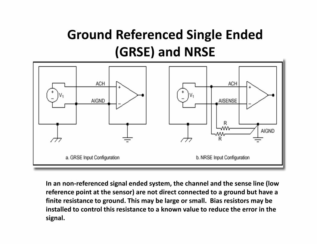
Ground Referenced Single Ended
(GRSE) and NRSE
In an non-referenced signal ended system, the channel and the sense line (low
reference point at the sensor) are not direct connected to a ground but have a
finite resistance to ground. This may be large or small. Bias resistors may be
installed to control this resistance to a known value to reduce the error in the
signal.

Bleed Resistors on thermocouples
• Because the – terminal of the Data Acquisition Input is a transistor device it sits naturally above the instrumentation ground. Usually around .7 volts.
• If the sensor is floating like a thermocouple, a battery or a piezo-electric device then the voltage being generated may be much less than .7 volts
• In this case current flows from the – terminal through the transducer back into the + junction and is read as noise at the input to the channel
• The way to prevent this is to put a bleed resistor of approximately 1k ohms on the negative input to the instrumentation ground
TC
+
-
Analog Input of Differential Data Acquisition Channel
R
Need bleed resistor here

Ground Loop
A ground loop is when there is difference in potential between two ground points
resulting in current flow between the two ground points. This can introduce error
into measurements through direct effects (raising the ground) and indirect effects
(electromagnetic coupling)


Wheatstone Bridge
EXo VRR
R
RR
RV ×
+
−
+
=
21
2
43
3

Bridge allows elimination of lead wire
resistance effects on accuracy
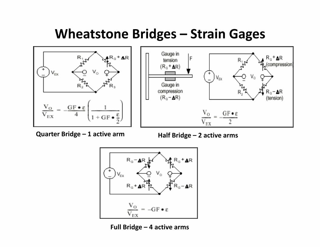
Wheatstone Bridges – Strain Gages
Quarter Bridge – 1 active arm Half Bridge – 2 active arms
Full Bridge – 4 active arms

Isolation• Isolation protects data acquisition and computer circuitry from potentially
harmful voltages in the equipment under measurement or control
• A number of technologies exist to isolate circuits
– Inductive – use transformers to isolate circuitry
• Only AC signals can cross the interface of the transformer
• Shorts are DC. Shorts pulling high current on one side of the transformer cannot effect the other side of the transformer.
– Optical – signal is converted into light and then the light is detected by an opto-detector. This all occurs within a plastic integrated circuit chip
• A favorite for digital signals
– Active electronics
• Modern amplifiers have technologies which can stand high voltage inputs and do not allow the high voltage to go through the circuitry to downstream stages
• Their output of the amplifier is limited by the supply voltage to the amplifier
• So a high voltage transient that is greater than the supply voltage to the amplifier cannot pass downstream of the amplifier
Multiplexing
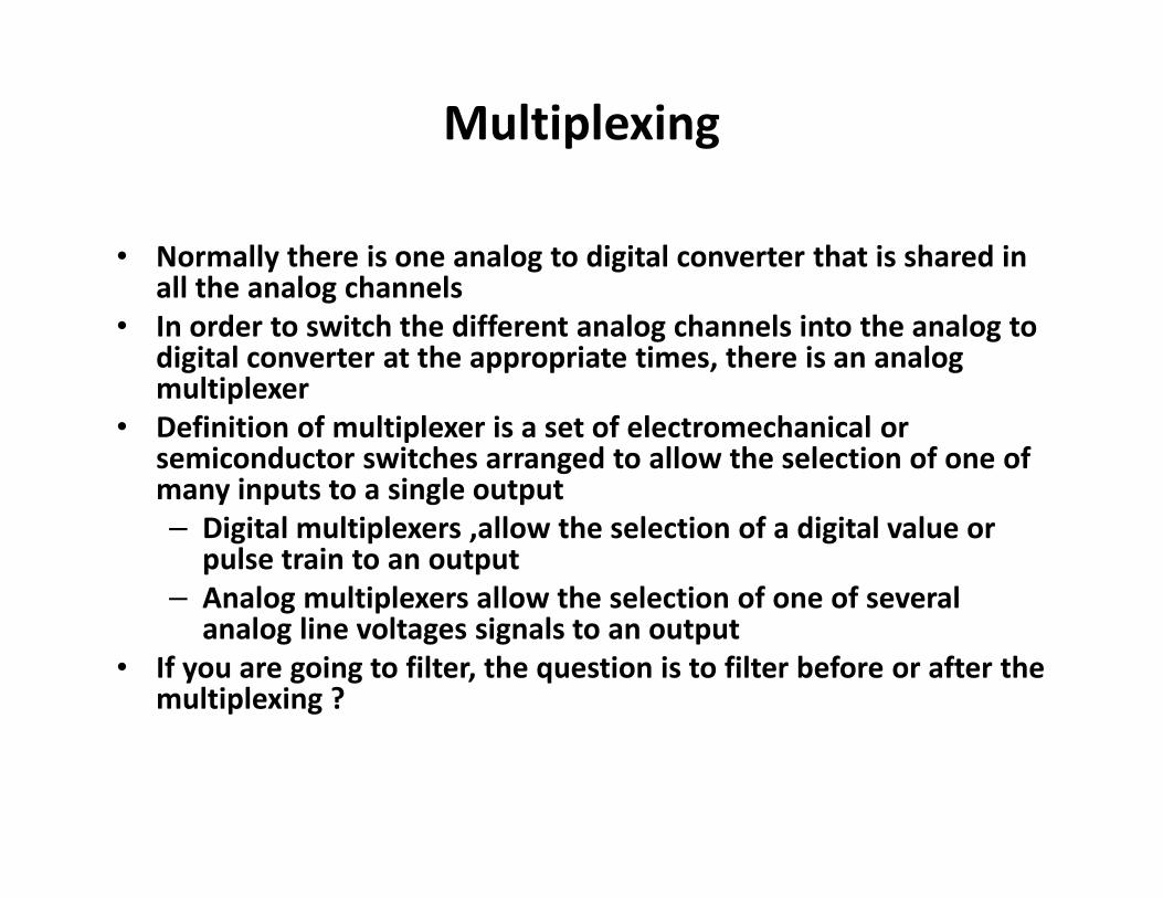
• Normally there is one analog to digital converter that is shared in all the analog channels
• In order to switch the different analog channels into the analog to digital converter at the appropriate times, there is an analog multiplexer
• Definition of multiplexer is a set of electromechanical or semiconductor switches arranged to allow the selection of one of many inputs to a single output
– Digital multiplexers ,allow the selection of a digital value or pulse train to an output
– Analog multiplexers allow the selection of one of several analog line voltages signals to an output
• If you are going to filter, the question is to filter before or after the multiplexing ?

Differential Voltage Measurement of
Multiple Channels Using Analog Multiplexers
From Labview
Data Acquisition
Basics Manual
Analog
Multiplexers

Multiplex Then Condition
CH0+
CH1+
CHX+
MULTIPLEXERS
IA
LOW PASS FILTER
CH0-
CH1-
CHX-
From: “Improved Signal Quality Through
Conditioning” byLauren Sjoboen available at
www.ni.com
Unless you dwell on each
channel for a significant time,
the effectiveness of the low
pass filter is decreased
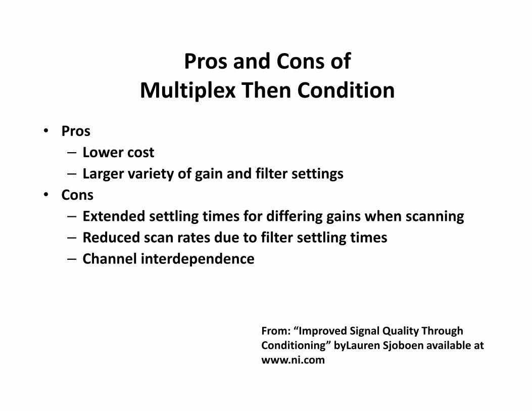
Pros and Cons of
Multiplex Then Condition
• Pros
– Lower cost
– Larger variety of gain and filter settings
• Cons
– Extended settling times for differing gains when scanning
– Reduced scan rates due to filter settling times
– Channel interdependence
From: “Improved Signal Quality Through
Conditioning” byLauren Sjoboen available at
www.ni.com

Condition Then Multiplex
MULTIPLEXER
IA
LOW PASS FILTER
CH0+
CH0-
IA
LOWER PASS FILTER
CHX+
CHX-
From: “Improved Signal Quality Through Conditioning” by Lauren
Sjoboen available at www.ni.com
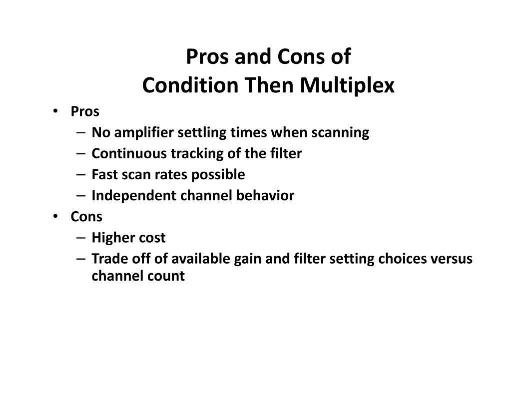
Pros and Cons of
Condition Then Multiplex• Pros
– No amplifier settling times when scanning
– Continuous tracking of the filter
– Fast scan rates possible
– Independent channel behavior
• Cons
– Higher cost
– Trade off of available gain and filter setting choices versus channel count