Embed Size (px)
Citation preview

The information in this document is subject to change without notice. 330-0010-R3.1 Copyright © 2009-2016 Page 1 of 58
SIFLEX02 TRANSCEIVER MODULE
Host Protocol Guide
Powered By
Last updated 5/16/2016
SiFLEX02 TRANSCEIVER MODULE
HOST PROTOCOL GUIDE
The information in this document is subject to change without notice. 330-0010-R3.1 Copyright © 2009-2016 Page 2 of 58
Table of Contents
1 Introduction ............................................................................................................... 5
1.1 Purpose & Scope ....................................................................................................................................... 5 1.2 Audience ................................................................................................................................................... 5 1.3 Applicable Documents .............................................................................................................................. 5 1.4 Revision History ........................................................................................................................................ 6
2 Host Protocol ............................................................................................................. 7
2.1 Default Serial Communications Settings .................................................................................................. 7 2.2 Host Serial Protocol Overview .................................................................................................................. 7 2.3 Handshaking............................................................................................................................................. 8 2.4 Wake Up From Low Power Mode ............................................................................................................. 8 2.5 Packet Spacing ......................................................................................................................................... 8 2.6 Example Host Protocol Message Exchange .............................................................................................. 8
3 Host Protocol Message Definitions ............................................................................. 9
3.1 Host Protocol Field Descriptions ............................................................................................................... 9
3.1.1 Host to Module ................................................................................................................................................. 9 3.1.2 Module to Host ................................................................................................................................................. 9 3.1.3 Manual Save ...................................................................................................................................................... 9 3.1.4 Message Length .............................................................................................................................................. 10 3.1.5 Payload Field Length ....................................................................................................................................... 10 3.1.6 Payload Field Name ......................................................................................................................................... 10 3.1.7 Description ...................................................................................................................................................... 10
3.2 Host Protocol Message Definitions ........................................................................................................ 11
3.2.1 Query Firmware Version ................................................................................................................................. 11 3.2.2 Set PAN ID ....................................................................................................................................................... 11 3.2.3 Query PAN ID .................................................................................................................................................. 11 3.2.4 Set Transceiver Address .................................................................................................................................. 12 3.2.5 Query Transceiver Address ............................................................................................................................. 12 3.2.6 Set RF Channel ................................................................................................................................................ 12 3.2.7 Query RF Channel ............................................................................................................................................ 12 3.2.8 Set Transmit Power Level ................................................................................................................................ 13 3.2.9 Query Transmit Power Level ........................................................................................................................... 13 3.2.10 Set Receiver Configuration .............................................................................................................................. 13 3.2.11 Query Receiver Configuration ......................................................................................................................... 13 3.2.12 Set Security Transmit Frame Counter ............................................................................................................. 13 3.2.13 Query Security Transmit Frame Counter ......................................................................................................... 14 3.2.14 Set Security Key ............................................................................................................................................... 14 3.2.15 Set Basic RF Settings ........................................................................................................................................ 15 3.2.16 Query Basic RF Settings ................................................................................................................................... 16 3.2.17 Save Settings To Non-Volatile Memory (NVM) ............................................................................................... 16 3.2.18 Reset Request ................................................................................................................................................. 16 3.2.19 Query Supply Voltage ...................................................................................................................................... 17 3.2.20 Query Statistics ............................................................................................................................................... 17 3.2.21 Clear Statistics ................................................................................................................................................. 17 3.2.22 Set Low Power Mode ...................................................................................................................................... 17

SiFLEX02 TRANSCEIVER MODULE
HOST PROTOCOL GUIDE
The information in this document is subject to change without notice. 330-0010-R3.1 Copyright © 2009-2016 Page 3 of 58
3.2.23 Set Host Data Rate .......................................................................................................................................... 18 3.2.24 Set RF Data Rate .............................................................................................................................................. 18 3.2.25 Query RF Data Rate ......................................................................................................................................... 18 3.2.26 Set Wakeup/Reset Settings ............................................................................................................................. 18 3.2.27 Query Wakeup/Reset Settings ........................................................................................................................ 19 3.2.28 Wakeup/Reset Alert Status ............................................................................................................................. 19 3.2.29 Set Static RF Test Mode ................................................................................................................................... 20 3.2.30 Send Simple Short Addressing RF Data Packet ................................................................................................ 21 3.2.31 Received Simple Short Addressing RF Data Packet ......................................................................................... 22 3.2.32 Send Advanced Short Addressing RF Data Packet ........................................................................................... 23 3.2.33 Received Advanced Short Addressing RF Data Packet .................................................................................... 24 3.2.34 Send Simple Long Addressing RF Data Packet ................................................................................................. 25 3.2.35 Received Simple Long Addressing RF Data Packet .......................................................................................... 26 3.2.36 Send Advanced Long Addressing RF Data Packet ............................................................................................ 27 3.2.37 Received Advanced Long Addressing RF Data Packet ..................................................................................... 28 3.2.38 Set FLEXConnect Configuration ....................................................................................................................... 29 3.2.39 Query FLEXConnect Configuration .................................................................................................................. 29 3.2.40 Send Simple Repeated RF Data Packet ............................................................................................................ 30 3.2.41 Received Simple Repeated RF Data Packet ..................................................................................................... 31 3.2.42 Send Source Routed RF Data Packet ............................................................................................................... 32 3.2.43 Received Source Routed RF Data Packet ......................................................................................................... 33 3.2.44 Received Promiscuous Mode RF Data Packet ................................................................................................. 34 3.2.45 Set Packet Error Rate Test Transmit Configuration ......................................................................................... 35 3.2.46 Set Packet Error Rate Test Receive Configuration ........................................................................................... 35 3.2.47 Packet Error Rate Packet Results .................................................................................................................... 36 3.2.48 Set/Query Packet Error Rate Test Status ......................................................................................................... 37 3.2.49 Channel Energy Scan ....................................................................................................................................... 38 3.2.50 Channel Energy Scan Response ....................................................................................................................... 38 3.2.51 Calibrate ADC Reference ................................................................................................................................. 39 3.2.52 Start RF Range Test ......................................................................................................................................... 39 3.2.53 Query RF Range Test Results – Slave Device ................................................................................................... 40 3.2.54 Received Range Test Packet ............................................................................................................................ 41 3.2.55 Repeater Test Mode – For Internal Use Only .................................................................................................. 42 3.2.56 Enable/Disable Terminal Debug Messages – For Internal Use Only ................................................................ 42 3.2.57 Terminal Debug Message – For Internal Use Only .......................................................................................... 42 3.2.58 Set Host Interface Configuration ..................................................................................................................... 42 3.2.59 Query Host Interface Configuration ................................................................................................................ 43 3.2.60 Set Beacon Payload ......................................................................................................................................... 44 3.2.61 Query Beacon Payload .................................................................................................................................... 45 3.2.62 Set Beacon Options ......................................................................................................................................... 46 3.2.63 Query Beacon Options .................................................................................................................................... 47 3.2.64 Beacon Message Transmit Host Ack ............................................................................................................... 48
4 Appendix A – Host Protocol Quick Start .................................................................... 49
4.1 Overview ................................................................................................................................................ 49 4.2 Configure and Save Settings ................................................................................................................... 49
4.2.1 PAN ID ............................................................................................................................................................. 49 4.2.2 Short/Long Addressing .................................................................................................................................... 49 4.2.3 RF Channel ...................................................................................................................................................... 50 4.2.4 RF Power Level ................................................................................................................................................ 50 4.2.5 Receive Filters ................................................................................................................................................. 50 4.2.6 Security Key ..................................................................................................................................................... 51 4.2.7 Configuring Modules ....................................................................................................................................... 51 4.2.8 Send/Receive RF Messages without ACK ........................................................................................................ 54

SiFLEX02 TRANSCEIVER MODULE
HOST PROTOCOL GUIDE
The information in this document is subject to change without notice. 330-0010-R3.1 Copyright © 2009-2016 Page 4 of 58
4.2.9 Send/Receive RF Messages with ACK .............................................................................................................. 55
5 Contacting LS Research ............................................................................................. 57
SiFLEX02 TRANSCEIVER MODULE
HOST PROTOCOL GUIDE
The information in this document is subject to change without notice. 330-0010-R3.1 Copyright © 2009-2016 Page 5 of 58
1 Introduction
1.1 Purpose & Scope
The purpose of this document is to describe in detail the message protocol used to communicate between a Host Device and the RF Module microprocessor.
1.2 Audience
This document is intended to be read by engineers and technical management. A general knowledge of common engineering practices is assumed.
1.3 Applicable Documents
The reader should be familiar with the following documentation:
SiFLEX02 Datasheet
SiFLEX02 Module User’s Guide

SiFLEX02 TRANSCEIVER MODULE
HOST PROTOCOL GUIDE
The information in this document is subject to change without notice. 330-0010-R3.1 Copyright © 2009-2016 Page 6 of 58
1.4 Revision History
Date Change Description Revision
8-3-09 Initial release. 1.0
11-3-09
Security and promiscuous mode are now supported. Updated power level and current table (Table 4). The following messages were changed – 0x0A, 0x0E, 0x10, 0x20, 0x22, 0x24, 0x26, 0x44, 0x8B, 0x91, 0xA1, 0xA3, 0xA5, 0xA7. The following messages were added - 0x0C, 0xD, 0x8C, 0x8D. The following message was removed - 0x0F.
1.1
6-15-10
Repeating and source routing are now supported. Added ability to disable Clear Channel Assessment (CCA) The following messages were changed – 0x20, 0x22, 0x24, 0x26. The following message are now supported – 0x28, 0x29, 0x2A, 0x2C, 0xA8, 0xA9, 0xAA, 0xAB, 0xAC, 0xAD. The following messages were added - 0x47, 0x48, 0xC7, 0xC8, 0xC9.
2.0
3-5-12
Added support for CTS host interface handshake signal, and min packet spacing. Added support for beacon messages. The following messages were added – 0x50 to 0x55 and 0xD0 to 0xD6.
3.0
5-24-16 Repeater Slot/Max Repeats 0XAB changed Updated to Laird format
3.1
Table 1 Revision History

SiFLEX02 TRANSCEIVER MODULE
HOST PROTOCOL GUIDE
The information in this document is subject to change without notice. 330-0010-R3.1 Copyright © 2009-2016 Page 7 of 58
2 Host Protocol
This document describes in detail the message protocol used to communicate between a Host Device and a SiFLEX02 RF Module microprocessor.
2.1 Default Serial Communications Settings
The serial communications interface to the module is via a simple UART. Transmit (TX) and receive (RX) are the only two signals required to communicate with the module, and the default communication settings are 19,200 baud, 8 data bits, no parity, and one stop bit (19,200 – 8N1).
2.2 Host Serial Protocol Overview
Header Payload Trailer
Field Start Byte Length Type Data Checksum End Byte
# Bytes 1 1 1 n 1 1
Figure 1 Host Protocol Message Format
Field Name Field Description
Start Byte The start byte is the first byte in a packet (0x01).
Length The total length of the entire packet in bytes (5 + n).
Type The packet type byte indentifies the intent of the packet.
Data n bytes of data which pertains to the type of the packet. The data is variable depending on the type of packet. For some packets there is no data.
Checksum The checksum is the least significant byte of the result of summing bytes from the Start Byte through the Payload.
End Byte The end byte is the last byte in a packet (0x04).
Table 2 Host Serial Protocol Field Descriptions

SiFLEX02 TRANSCEIVER MODULE
HOST PROTOCOL GUIDE
The information in this document is subject to change without notice. 330-0010-R3.1 Copyright © 2009-2016 Page 8 of 58
2.3 Handshaking
The module supports handshaking with the host device for flow control. The Clear-to-Send (CTS) signal is an output from the module which is used to tell the host device that the module can accept serial packets. By default the handshaking signal is not used, however it can independently be enabled in the “Set Host Interface Configuration” message (type 0x50). The CTS signal is active low, meaning that when it is low (logic 0) the module is ready to accept data.
2.4 Wake Up From Low Power Mode
To wake the SiFLEX02 module out of low power mode, drive the UART receive pin (module pin #36) low for a minimum of 20uS. Alternatively a dummy byte of 0x00 can be sent, assuming the baud rate is 460,800 or below.
2.5 Packet Spacing
Care should be given with respect to how fast back-to-back packets are sent to the module. Depending on the serial host baud rate, and how much processing the module is doing, packets sent too close back-to-back could result in the second packet being dropped. In general 1msec of spacing should be more than adequate and could be much lower. The developer should characterize this time based on the specifics of their application.
The module will send out packets to the host device as fast as possible, which depending on the host application might be too fast resulting in the host losing packets. If this is a problem a minimum outgoing packet spacing can be configured with the “Set Host Interface Configuration” message (type 0x50).
2.6 Example Host Protocol Message Exchange
Below is an example that shows what a complete host serial packet would look like for a “Query PAN ID” and a “Respond with PAN ID” message exchange. This example assumes the PAN ID is being queried from the local “hardwired” module.
Host -> Module – (Query PAN ID – Type 0x03) < 0x01 0x05 0x03 0x09 0x04 >
Module -> Host – (Respond with PAN ID – Type 0x83) < 0x01 0x07 0x83 0x64 0x00 0xEF 0x04>

SiFLEX02 TRANSCEIVER MODULE
HOST PROTOCOL GUIDE
The information in this document is subject to change without notice. 330-0010-R3.1 Copyright © 2009-2016 Page 9 of 58
3 Host Protocol Message Definitions
The information contained in this section is abbreviated and omits the header and trailer information which is common to all serial host messages.
3.1 Host Protocol Field Descriptions
3.1.1 Host to Module
This field shows the message type for messages that get sent from the host device to the module, and are within the range of 0x01 through 0x7F.
Host to Module
Module to Host
Manual Save
Message Length
Payload Length
Payload Name
Description
Figure 2 Host to Module
3.1.2 Module to Host
This field shows the message type for messages that get sent from the module to the host device, and are within the range of 0x81 through 0xFF.
Host to Module
Module to Host
Manual Save
Message Length
Payload Length
Payload Name
Description
Figure 3 Module to Host
3.1.3 Manual Save
This column will contain an “x” if the settings contained in the message can be manually saved to non-volatile memory (NVM). To manually save the settings to NVM issue a “Save Settings To Non-Volatile Memory” command (Msg Type 0x12). All settings contained within messages that have an “x” in the Manual Save column are saved when the “Save Settings To NVM” command is issued. Therefore it is best to change all settings and then issue the “Save Settings to NVM” command only once.
Host to Module
Module to Host
Manual Save Message Length
Payload Length
Payload Name
Description
Figure 4 Manual Save

SiFLEX02 TRANSCEIVER MODULE
HOST PROTOCOL GUIDE
The information in this document is subject to change without notice. 330-0010-R3.1 Copyright © 2009-2016 Page 10 of 58
3.1.4 Message Length
This column contains the length of the entire message, which consists of the header (3 bytes), payload, and trailer (2 bytes). The minimum sized message is 5 bytes and occurs in messages that contain no payload.
Host to Module
Module to Host
Manual Save Message Length
Payload Length
Payload Name
Description
Figure 5 Message Length
3.1.5 Payload Field Length
This column lists the length in bytes of each payload field.
Host to Module
Module to Host
Manual Save Message Length
Payload Length
Payload Name
Description
Figure 6 Payload Field Length
3.1.6 Payload Field Name
This column contains a list of the fields that are contained within each message.
Host to Module
Module to Host
Manual Save Message Length
Payload Length
Payload Name
Description
Figure 7 Payload Field Name
3.1.7 Description
This column details what the message does or what is contained in the payload field.
Host to Module
Module to Host
Manual Save Message Length
Payload Length
Payload Name
Description
Figure 8 Description

SiFLEX02 TRANSCEIVER MODULE
HOST PROTOCOL GUIDE
The information in this document is subject to change without notice. 330-0010-R3.1 Copyright © 2009-2016 Page 11 of 58
3.2 Host Protocol Message Definitions
Host to Module
Module to Host
Manual Save
Message Length
Payload Length
Payload Name
Description
3.2.1 Query Firmware Version
0x01 -
5 -
- 0x81 12+n
1 Module
Identifier Identifies this module as a SiFLEX02 module (0x01).
1 Version Major Version major number.
1 Version Minor Version minor number.
1 Version Month
Version month (1 - 12).
1 Version Day Version day (1 - 31).
1 Version Year Version year (0 - 99).
1 Version String
Length Length of version string (0 - 32 bytes).
n Version String Version string (0 - 32 bytes in length).
3.2.2 Set PAN ID
0x02 - X
7 2 PAN ID Two byte PAN ID (LSB to MSB) of the network this transceiver should operate on.
- 0x82 5 -
3.2.3 Query PAN ID
0x03 -
5 -
- 0x83 7 2 PAN ID Two byte PAN ID (LSB to MSB) of the network this transceiver should operate on.

SiFLEX02 TRANSCEIVER MODULE
HOST PROTOCOL GUIDE
The information in this document is subject to change without notice. 330-0010-R3.1 Copyright © 2009-2016 Page 12 of 58
Host to Module
Module to Host
Manual Save
Message Length
Payload Length
Payload Name
Description
3.2.4 Set Transceiver Address
0x04 - X
15
2 Short
Transceiver Address
Two byte transceiver short address (LSB to MSB). When the short address is set to 0xFFFF the long address is used instead of the short address.
8 Long
Transceiver Address
Eight byte transceiver long address (LSB to MSB). Do not set the transceiver long address to a value of 0x0000000000000000. To use the long address, set the short address to 0xFFFF.
- 0x84 5 -
3.2.5 Query Transceiver Address
0x05 -
5 -
- 0x85 15
2 Short
Transceiver Address
Two byte transceiver short address (LSB to MSB). When the short address is set to 0xFFFF the long address is used instead of the short address.
8 Long
Transceiver Address
Eight byte transceiver long address (LSB to MSB). To use the long address, set the short address to 0xFFFF.
3.2.6 Set RF Channel
0x06 - X
6 1 RF Channel
The RF channel that the transceiver operates on (1-10). 1 = 906 MHz 2 = 908 MHz 3 = 910 MHz 4 = 912 MHz 5 = 914 MHz 6 = 916 MHz 7 = 918 MHz 8 = 920 MHz 9 = 922 MHz 10 = 924 MHz
- 0x86 5 -
3.2.7 Query RF Channel
0x07 -
5 -
- 0x87 6 1 RF Channel The RF channel that the transceiver operates on (1-10).

SiFLEX02 TRANSCEIVER MODULE
HOST PROTOCOL GUIDE
The information in this document is subject to change without notice. 330-0010-R3.1 Copyright © 2009-2016 Page 13 of 58
Host to Module
Module to Host
Manual Save
Message Length
Payload Length
Payload Name
Description
3.2.8 Set Transmit Power Level
0x08 - X
6 1 RF Power
Level RF power level (0-21).
- 0x88 5 -
3.2.9 Query Transmit Power Level
0x09 -
5 -
- 0x89 6 1 RF Power
Level RF power level (0-21).
3.2.10 Set Receiver Configuration
0x0A - X
7 1 Receive Filters
Bitmask of the receive filtering. Bit 0: Allow Broadcast Address (0 = disable, 1 = enable) Bit 1: Allow Broadcast PAN ID (0 = disable, 1 = enable) Bit 2: Promiscuous Mode (0 = disable, 1 = enable) Bit 3: Allow Secured Packets (0 = disable, 1 = enable)
1 Reserved Reserved for future use. Set to 0.
- 0x8A 5 -
3.2.11 Query Receiver Configuration
0x0B -
5 -
- 0x8B 7 1 Receive Filters
Bitmask of the receive filtering. Bit 0: Allow Broadcast Address (0 = disable, 1 = enable) Bit 1: Allow Broadcast PAN ID (0 = disable, 1 = enable) Bit 2: Promiscuous Mode (0 = disable, 1 = enable) Bit 3: Allow Secured Packets (0 = disable, 1 = enable)
1 Reserved Reserved for future use. Set to 0.
3.2.12 Set Security Transmit Frame Counter
0x0C - 11 4 Transmit
Frame Counter
Four byte transmit frame counter (LSB to MSB). This frame counter is used with RF messages transmitted with security to insure sequential freshness. This sets the starting frame count and is automatically incremented on every secured packet sent.

SiFLEX02 TRANSCEIVER MODULE
HOST PROTOCOL GUIDE
The information in this document is subject to change without notice. 330-0010-R3.1 Copyright © 2009-2016 Page 14 of 58
Host to Module
Module to Host
Manual Save
Message Length
Payload Length
Payload Name
Description
2 Reserved Reserved for future use. Set to 0.
- 0x8C 5 -
3.2.13 Query Security Transmit Frame Counter
0x0D -
5 -
- 0x8D 11 4
Transmit Frame
Counter
Four byte transmit frame counter (LSB to MSB). This frame counter is used with RF messages transmitted with security to insure sequential freshness. This returned value is the next frame count that will be transmitted with a secured message.
2 Reserved Reserved for future use. Set to 0.
3.2.14 Set Security Key
0x0E - X
22 1 Reserved Reserved for future use. Set to 0.
16 Security Key Sixteen byte encryption key (LSB to MSB).
- 0x8E 5 -

SiFLEX02 TRANSCEIVER MODULE
HOST PROTOCOL GUIDE
The information in this document is subject to change without notice. 330-0010-R3.1 Copyright © 2009-2016 Page 15 of 58
Host to Module
Module to Host
Manual Save
Message Length
Payload Length
Payload Name
Description
3.2.15 Set Basic RF Settings
0x10 - X
39
2 PAN ID Two byte PAN ID (LSB to MSB) of the network this transceiver should operate on.
2 Short
Transceiver Address
Two byte transceiver short address (LSB to MSB). When the short address is set to 0xFFFF the long address is used instead of the short address.
8 Long
Transceiver Address
Eight byte transceiver long address (LSB to MSB). Do not set the transceiver long address to a value of 0x0000000000000000. To use the long address, set the short address to 0xFFFF.
1 RF Channel
The RF channel that the transceiver operates on (1-10). 1 = 906 MHz 2 = 908 MHz 3 = 910 MHz 4 = 912 MHz 5 = 914 MHz 6 = 916 MHz 7 = 918 MHz 8 = 920 MHz 9 = 922 MHz 10 = 924 MHz
1 RF Power
Level RF power level (0-21).
1 Receive Filters
Bitmask of the receive filtering. Bit 0: Allow Broadcast Address (0 = disable, 1 = enable) Bit 1: Allow Broadcast PAN ID (0 = disable, 1 = enable) Bit 2: Promiscuous Mode (0 = disable, 1 = enable) Bit 3: Allow Secured Packets (0 = disable, 1 = enable)
3 Reserved Reserved for future use. Set to 0.
16 Security Key Sixteen byte encryption key (LSB to MSB).
- 0x90 5 -
SiFLEX02 TRANSCEIVER MODULE
HOST PROTOCOL GUIDE
The information in this document is subject to change without notice. 330-0010-R3.1 Copyright © 2009-2016 Page 16 of 58
Host to Module
Module to Host
Manual Save
Message Length
Payload Length
Payload Name
Description
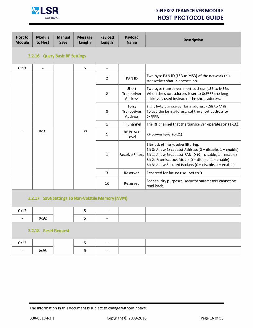
3.2.16 Query Basic RF Settings
0x11 -
5 -
- 0x91 39
2 PAN ID Two byte PAN ID (LSB to MSB) of the network this transceiver should operate on.
2 Short
Transceiver Address
Two byte transceiver short address (LSB to MSB). When the short address is set to 0xFFFF the long address is used instead of the short address.
8 Long
Transceiver Address
Eight byte transceiver long address (LSB to MSB). To use the long address, set the short address to 0xFFFF.
1 RF Channel The RF channel that the transceiver operates on (1-10).
1 RF Power
Level RF power level (0-21).
1 Receive Filters
Bitmask of the receive filtering. Bit 0: Allow Broadcast Address (0 = disable, 1 = enable) Bit 1: Allow Broadcast PAN ID (0 = disable, 1 = enable) Bit 2: Promiscuous Mode (0 = disable, 1 = enable) Bit 3: Allow Secured Packets (0 = disable, 1 = enable)
3 Reserved Reserved for future use. Set to 0.
16 Reserved For security purposes, security parameters cannot be read back.
3.2.17 Save Settings To Non-Volatile Memory (NVM)
0x12 -
5 -
- 0x92 5 -
3.2.18 Reset Request
0x13 -
5 -
- 0x93 5 -

SiFLEX02 TRANSCEIVER MODULE
HOST PROTOCOL GUIDE
The information in this document is subject to change without notice. 330-0010-R3.1 Copyright © 2009-2016 Page 17 of 58
Host to Module
Module to Host
Manual Save
Message Length
Payload Length
Payload Name
Description
3.2.19 Query Supply Voltage
0x14 -
5 -
- 0x94 9
2 Supply
ADC Reading
The supply voltage ADC reading (LSB to MSB). The supply voltage can be determined by the following formula: Supply Voltage = ((Supply ADC Reading x Voltage Reference) /409,400). Ex: Voltage Reference = 1.011v (1011), ADC Reading = 926, Supply Voltage => 3.27.
2 Voltage
Reference
The Voltage Reference in millivolts (LSB to MSB). For example a reference voltage of 1.011V will be passed as 1011.
3.2.20 Query Statistics
0x15 -
5 -
- 0x95 21
4 Packets Sent Four byte value for RF packets sent (LSB to MSB).
4 Acks Received Four byte value for RF acknowledgements received (LSB to MSB).
4 Packets
Received Four byte value for RF packets received (LSB to MSB).
4 Broadcast
Packets Received
Four byte value for RF broadcast packets received (LSB to MSB).
3.2.21 Clear Statistics
0x16 -
5 -
- 0x96 5 -
3.2.22 Set Low Power Mode
To wake the SiFLEX02 module out of low power mode, drive the UART receive pin (module pin #36) low for a minimum of 20uS. Alternatively a dummy byte of 0x00 can be sent, assuming the baud rate is 460,800 or below.
0x17 -
6 1 Reserved Reserved for future use. Set to 0.
- 0x97 5 -

SiFLEX02 TRANSCEIVER MODULE
HOST PROTOCOL GUIDE
The information in this document is subject to change without notice. 330-0010-R3.1 Copyright © 2009-2016 Page 18 of 58
Host to Module
Module to Host
Manual Save
Message Length
Payload Length
Payload Name
Description
3.2.23 Set Host Data Rate
0x18 -
6 1 Baud Rate
Serial baud rate setting. 0 = 1,200, 1 = 2,400, 2 = 4,800, 3 = 9,600, 4 = 19,200, 5 = 38,400, 6 = 57,600, 7 = 115,200, 8 = 230,400, 9 = 460,800, 10 = 921,600.
Note: When this command is sent to the module, not only is the baud rate changed, but all the settings are saved to NVM.
- 0x98 5 -
3.2.24 Set RF Data Rate
0x19 - X
6 1 Data Rate
RF data rate setting. 0 = BPSK 40kbps 1 = OQPSK-SIN 250kbps 2 = OQPSK-SIN 1Mbps Scrambler On
- 0x99 5 -
3.2.25 Query RF Data Rate
0x1A -
5 -
- 0x9A 6 1 Data Rate
RF data rate setting. 0 = BPSK 40kbps 1 = OQPSK-SIN 250kbps 2 = OQPSK-SIN 1Mbps Scrambler On
3.2.26 Set Wakeup/Reset Settings
0x1C - X
7
1 Wakeup Setting
Setting that determines behavior on a wakeup from sleep. When set to 0x00 the host is not alerted. When set to 0x01 a wakeup results in a “Wakeup/Reset Alert Status” message being sent to the host (see message type 0x9E).
1 Reset Setting
Setting that determines behavior on a reset. When set to 0x00 the host is not alerted. When set to 0x01 a reset results in a “Wakeup/Reset Alert Status” message being sent to the host (see message type 0x9E).
- 0x9C 5 -

SiFLEX02 TRANSCEIVER MODULE
HOST PROTOCOL GUIDE
The information in this document is subject to change without notice. 330-0010-R3.1 Copyright © 2009-2016 Page 19 of 58
Host to Module
Module to Host
Manual Save
Message Length
Payload Length
Payload Name
Description
3.2.27 Query Wakeup/Reset Settings
0x1D -
5 -
- 0x9D 7
1 Wakeup Setting
Setting that determines behavior on a wakeup from sleep. When set to 0x00 the host is not alerted. When set to 0x01 a wakeup results in a “Wakeup/Reset Alert Status” message being sent to the host (see message type 0x9E).
1 Reset Setting
Setting that determines behavior on a reset. When set to 0x00 the host is not alerted. When set to 0x01 a reset results in a “Wakeup/Reset Alert Status” message being sent to the host (see message type 0x9E).
3.2.28 Wakeup/Reset Alert Status
NA -
- -
- 0x9E 6 1 Wakeup/
Reset Alert Status
The wakeup/reset alert status byte describes whether the module was awoken from sleep (0x00) or reset (0x01).

SiFLEX02 TRANSCEIVER MODULE
HOST PROTOCOL GUIDE
The information in this document is subject to change without notice. 330-0010-R3.1 Copyright © 2009-2016 Page 20 of 58
Host to Module
Module to Host
Manual Save
Message Length
Payload Length
Payload Name
Description
3.2.29 Set Static RF Test Mode
0x1F -
11
1 Test Mode
Test Mode: 0 = Idle (transmit and receive not active) 1 = Receive 2 = Transmit Unmodulated 0 3 = Transmit Unmodulated 1 4 = Transmit Modulated 5 = Pseudo Random Binary Sequence (todo: validate if this is supported)
1 RF Channel The RF channel that the transceiver operates on while in test mode (1-10).
1 RF Power
Level RF power level used for the transmit modes (0-21).
1 Reserved Reserved for future use. Set to 0.
1 RF Phy Mode
RF physical layer mode which establishes the modulation format and RF data rate. 0 = BPSK 40kbps 1 = OQPSK-SIN 250kbps 2 = OQPSK-SIN 500kbps 3 = OQPSK-SIN 1Mbps Scrambler On 4 = OQPSK-SIN 1Mbps Scrambler Off 5 = OQPSK-RC 250kbps 6 = OQPSK-RC 500kbps 7 = OQPSK-RC 1Mbps Scrambler On 8 = OQPSK-RC 1Mbps Scrambler Off
1 Matching Control
Capacitor Match Value (0-15): 0 = 0fF 1 = 36fF 2 = 72fF … 15 = 540fF
- 0x9F 5 -

SiFLEX02 TRANSCEIVER MODULE
HOST PROTOCOL GUIDE
The information in this document is subject to change without notice. 330-0010-R3.1 Copyright © 2009-2016 Page 21 of 58
Host to Module
Module to Host
Manual Save
Message Length
Payload Length
Payload Name
Description
3.2.30 Send Simple Short Addressing RF Data Packet
This message is used to send a RF packet to a destination transceiver using short addressing. It is assumed that the destination transceiver’s PAN ID is the same as the PAN ID of the source transceiver.
0x20 -
9+n
1 Options
Bitmask of the transmit options. Bit 0: Retries/Acks (0 = disable, 1 = enable)
Note: If CCA is disabled, Retries/Acks are not used.
Bit 1: Use Security (0 = disable, 1 = enable) Bit 2: Disable CCA (0 = enable, 1 = disable)
2 Destination Transceiver
Address
Two byte destination transceiver address (LSB to MSB). This is the address of the transceiver the message is being sent to. Setting this address to 0xFFFF results in the message being broadcast to all transceivers.
1 Packet ID Packet ID.
n n Data Bytes Data to be sent over the RF link (n bytes). The valid range of data bytes is between 1 and 112 if security is not used, and 1 and 98 if security is used.
- 0xA0 7
1 Packet ID Packet ID.
1 Ack/Nack Acknowledgement or Non-Acknowledgement of the successful transmission of the RF packet (0x00 = Nack, 0x01 = Ack).

SiFLEX02 TRANSCEIVER MODULE
HOST PROTOCOL GUIDE
The information in this document is subject to change without notice. 330-0010-R3.1 Copyright © 2009-2016 Page 22 of 58
Host to Module
Module to Host
Manual Save
Message Length
Payload Length
Payload Name
Description
3.2.31 Received Simple Short Addressing RF Data Packet
This message gets sent to the host when a RF packet is received from a transceiver using short addressing. It is assumed that the source transceiver’s PAN ID is the same as the PAN ID of the destination transceiver.
NA -
- -
- 0xA1 17+n
1 Security Status
This byte indicates whether or not the received packet was secured (0 = not secured, 1 = secured). If the received packet was secured, the frame counter is valid, else the frame counter is all zeros.
4 Frame
Counter
Four byte frame counter (LSB to MSB) of the received packet, if the packet was secured. For non-secured packets the frame counter is all zeros.
1 Reserved Reserved for future use. Set to 0.
1 LQI Link Quality Indicator which gives feedback to the strength of the received packet.
2 Destination Transceiver
Address
Two byte destination transceiver address (LSB to MSB). This is the address of the transceiver the message is being sent to. This address should either be the source address of the transceiver that received it, or the broadcast address (0xFFFF).
2 Source
Transceiver Address
Two byte source transceiver address (LSB to MSB). This is the address of the device that originated the message.
1 Packet ID Packet ID.
n n Data Bytes Data bytes received over the RF link (n bytes).

SiFLEX02 TRANSCEIVER MODULE
HOST PROTOCOL GUIDE
The information in this document is subject to change without notice. 330-0010-R3.1 Copyright © 2009-2016 Page 23 of 58
Host to Module
Module to Host
Manual Save
Message Length
Payload Length
Payload Name
Description
3.2.32 Send Advanced Short Addressing RF Data Packet
This message is used to send a RF packet to a destination transceiver using short addressing. In addition to the destination transceiver’s ID, it is required to designate the destination PAN ID. This allows for sending packets between PANs (intra PAN).
0x22 -
11+n
1 Options
Bitmask of the transmit options. Bit 0: Retries/Acks (0 = disable, 1 = enable)
Note: If CCA is disabled, Retries/Acks are not used.
Bit 1: Use Security (0 = disable, 1 = enable) Bit 2: Disable CCA (0 = enable, 1 = disable)
2 Destination
PAN ID
Two byte destination PAN ID (LSB to MSB). This is the PAN ID of the transceiver the message is being sent to. Setting this address to 0xFFFF results in the message being broadcast to all PAN IDs.
2 Destination Transceiver
Address
Two byte destination transceiver address (LSB to MSB). This is the address of the transceiver the message is being sent to. Setting this address to 0xFFFF results in the message being broadcast to all transceivers.
1 Packet ID Packet ID.
n n Data Bytes Data to be sent over the RF link (n bytes). The valid range of data bytes is between 1 and 110 if security is not used, and 1 and 96 if security is used.
- 0xA2 7
1 Packet ID Packet ID.
1 Ack/Nack Acknowledgement or Non-Acknowledgement of the successful transmission of the RF packet (0x00 = Nack, 0x01 = Ack).
SiFLEX02 TRANSCEIVER MODULE
HOST PROTOCOL GUIDE
The information in this document is subject to change without notice. 330-0010-R3.1 Copyright © 2009-2016 Page 24 of 58
Host to Module
Module to Host
Manual Save
Message Length
Payload Length
Payload Name
Description
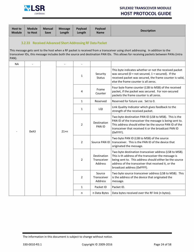
3.2.33 Received Advanced Short Addressing RF Data Packet
This message gets sent to the host when a RF packet is received from a transceiver using short addressing. In addition to the transceiver IDs, this message includes both the source and destination PAN IDs. This allows for receiving packets between PANs (intra PAN).
NA -
- -
- 0xA3 21+n
1 Security Status
This byte indicates whether or not the received packet was secured (0 = not secured, 1 = secured). If the received packet was secured, the frame counter is valid, else the frame counter is all zeros.
4 Frame
Counter
Four byte frame counter (LSB to MSB) of the received packet, if the packet was secured. For non-secured packets the frame counter is all zeros.
1 Reserved Reserved for future use. Set to 0.
1 LQI Link Quality Indicator which gives feedback to the strength of the received packet.
2 Destination
PAN ID
Two byte destination PAN ID (LSB to MSB). This is the PAN ID of the transceiver the message is being sent to. This address should either be the source PAN ID of the transceiver that received it or the broadcast PAN ID (0xFFFF).
2 Source PAN ID Two byte PAN ID (LSB to MSB) of the source transceiver. This is the PAN ID of the device that originated the message.
2 Destination Transceiver
Address
Two byte destination transceiver address (LSB to MSB). This is th address of the transceiver the message is being sent to. This address should either be the source address of the transceiver that received it, or the broadcast address (0xFFFF).
2 Source
Transceiver Address
Two byte source transceiver address (LSB to MSB). This is the address of the device that originated the message.
1 Packet ID Packet ID.
n n Data Bytes Data bytes received over the RF link (n bytes).

SiFLEX02 TRANSCEIVER MODULE
HOST PROTOCOL GUIDE
The information in this document is subject to change without notice. 330-0010-R3.1 Copyright © 2009-2016 Page 25 of 58
Host to Module
Module to Host
Manual Save
Message Length
Payload Length
Payload Name
Description
3.2.34 Send Simple Long Addressing RF Data Packet
This message is used to send a RF packet to a destination transceiver using long addressing. It is assumed that the destination transceiver’s PAN ID is the same as the PAN ID of the source transceiver.
0x24 -
15+n
1 Options
Bitmask of the transmit options. Bit 0: Retries/Acks (0 = disable, 1 = enable)
Note: If CCA is disabled, Retries/Acks are not used.
Bit 1: Use Security (0 = disable, 1 = enable) Bit 2: Disable CCA (0 = enable, 1 = disable)
8 Destination Transceiver
Address
Eight byte destination transceiver address (LSB to MSB). This is the address of the transceiver the message is being sent to.
1 Packet ID Packet ID.
n n Data Bytes Data to be sent over the RF link (n bytes). The valid range of data bytes is between 1 and 100 if security is not used, and 1 and 86 if security is used.
- 0xA4 7
1 Packet ID Packet ID.
1 Ack/Nack Acknowledgement or Non-Acknowledgement of the successful transmission of the RF packet (0x00 = Nack, 0x01 = Ack).

SiFLEX02 TRANSCEIVER MODULE
HOST PROTOCOL GUIDE
The information in this document is subject to change without notice. 330-0010-R3.1 Copyright © 2009-2016 Page 26 of 58
Host to Module
Module to Host
Manual Save
Message Length
Payload Length
Payload Name
Description
3.2.35 Received Simple Long Addressing RF Data Packet
This message gets sent to the host when a RF packet is received from a transceiver using long addressing. It is assumed that the source transceiver’s PAN ID is the same as the PAN ID of the destination transceiver.
NA -
- -
- 0xA5 29+n
1 Security Status
This byte indicates whether or not the received packet was secured (0 = not secured, 1 = secured). If the received packet was secured, the frame counter is valid, else the frame counter is all zeros.
4 Frame
Counter
Four byte frame counter (LSB to MSB) of the received packet, if the packet was secured. For non-secured packets the frame counter is all zeros.
1 Reserved Reserved for future use. Set to 0.
1 LQI Link Quality Indicator which gives feedback to the strength of the received packet.
8 Destination Transceiver
Address
Eight byte destination transceiver address (LSB to MSB). This is the address of the transceiver the message is being sent to.
8 Source
Transceiver Address
Eight byte source transceiver address (LSB to MSB). This is the address of the device that originated the message.
1 Packet ID Packet ID.
n n Data Bytes Data bytes received over the RF link (n bytes).

SiFLEX02 TRANSCEIVER MODULE
HOST PROTOCOL GUIDE
The information in this document is subject to change without notice. 330-0010-R3.1 Copyright © 2009-2016 Page 27 of 58
Host to Module
Module to Host
Manual Save
Message Length
Payload Length
Payload Name
Description
3.2.36 Send Advanced Long Addressing RF Data Packet
This message is used to send a RF packet to a destination transceiver using long addressing. In addition to the destination transceiver’s ID, it is required to designate the destination PAN ID. This allows for sending packets between PANs (intra PAN).
0x26 -
17+n
1 Options
Bitmask of the transmit options. Bit 0: Retries/Acks (0 = disable, 1 = enable)
Note: If CCA is disabled, Retries/Acks are not used.
Bit 1: Use Security (0 = disable, 1 = enable) Bit 2: Disable CCA (0 = enable, 1 = disable)
2 Destination
PAN ID
Two byte destination PAN ID (LSB to MSB). This is the PAN ID of the transceiver the message is being sent to. Setting this address to 0xFFFF results in the message being broadcast to all PAN IDs.
8 Destination Transceiver
Address
Eight byte destination transceiver address (LSB to MSB). This is the address of the transceiver the message is being sent to.
1 Packet ID Packet ID.
n n Data Bytes Data to be sent over the RF link (n bytes). The valid range of data bytes is between 1 and 98 if security is not used, and 1 and 84 if security is used.
- 0xA6 7
1 Packet ID Packet ID.
1 Ack/Nack Acknowledgement or Non-Acknowledgement of the successful transmission of the RF packet (0x00 = Nack, 0x01 = Ack).

SiFLEX02 TRANSCEIVER MODULE
HOST PROTOCOL GUIDE
The information in this document is subject to change without notice. 330-0010-R3.1 Copyright © 2009-2016 Page 28 of 58
Host to Module
Module to Host
Manual Save
Message Length
Payload Length
Payload Name
Description
3.2.37 Received Advanced Long Addressing RF Data Packet
This message gets sent to the host when a RF packet is received from a transceiver using long addressing. In addition to the transceiver IDs, this message includes both the source and destination PAN IDs. This allows for receiving packets between PANs (intra PAN).
NA -
- -
- 0xA7 33+n
1 Security Status
This byte indicates whether or not the received packet was secured (0 = not secured, 1 = secured). If the received packet was secured, the frame counter is valid, else the frame counter is all zeros.
4 Frame
Counter
Four byte frame counter (LSB to MSB) of the received packet, if the packet was secured. For non-secured packets the frame counter is all zeros.
1 Reserved Reserved for future use. Set to 0.
1 LQI Link Quality Indicator which gives feedback to the strength of the received packet.
2 Destination
PAN ID
Two byte destination PAN ID (LSB to MSB). This is the PAN ID of the transceiver the message is being sent to. This address should either be the source PAN ID of the transceiver that received it or the broadcast PAN ID (0xFFFF).
2 Source PAN ID Two byte PAN ID (LSB to MSB) of the source transceiver. This is the PAN ID of the device that originated the message.
8 Destination Transceiver
Address
Eight byte destination transceiver address (LSB to MSB). This is the address of the transceiver the message is being sent to.
8 Source
Transceiver Address
Eight byte source transceiver address (LSB to MSB). This is the address of the device that originated the message.
1 Packet ID Packet ID.
n n Data Bytes Data bytes received over the RF link (n bytes).

SiFLEX02 TRANSCEIVER MODULE
HOST PROTOCOL GUIDE
The information in this document is subject to change without notice. 330-0010-R3.1 Copyright © 2009-2016 Page 29 of 58
Host to Module
Module to Host
Manual Save
Message Length
Payload Length
Payload Name
Description
3.2.38 Set FLEXConnect Configuration
0x28 - X
9
1 Max
Repeaters Maximum number of repeaters in the system (1-15).
1 Max Repeats Maximum number of repeats allowed (1-7). Note that maximum hop count is Max Repeats + 1.
1 Device Type Sets the device type as either a node (0x00), which does not repeat, or a repeater (0x01), which does repeat.
1 Timeslot The timeslot assigned to the repeater (1 - Max Repeaters).
- 0xA8 5 -
3.2.39 Query FLEXConnect Configuration
0x29 -
5 -
- 0xA9 9
1 Max
Repeaters Maximum number of repeaters in the system (1-15).
1 Max Repeats Maximum number of repeats allowed (1-7). Note that maximum hop count is Max Repeats + 1.
1 Device Type Sets the device type as either a node (0x00), which does not repeat, or a repeater (0x01), which does repeat.
1 Timeslot The timeslot assigned to the repeater (1 - Max Repeaters).

SiFLEX02 TRANSCEIVER MODULE
HOST PROTOCOL GUIDE
The information in this document is subject to change without notice. 330-0010-R3.1 Copyright © 2009-2016 Page 30 of 58
Host to Module
Module to Host
Manual Save
Message Length
Payload Length
Payload Name
Description
3.2.40 Send Simple Repeated RF Data Packet
This message is used to send a RF packet to a destination transceiver using the repeating mechanism and short addressing. It is assumed that the destination transceiver’s PAN ID is the same as the PAN ID of the source transceiver.
0x2A -
9+n
1 Options
Bitmask of the transmit options. Bit 0: Not used (always 0) Bit 1: Use Security (0 = disable, 1 = enable) Bit 2: Not used (always 0)
2 Destination Transceiver
Address
Two byte destination transceiver address (LSB to MSB). This is the address of the transceiver the message is being sent to. Setting this address to 0xFFFF results in the message being broadcast to all transceivers.
1 Packet ID Packet ID.
n n Data Bytes
Data to be sent over the RF link (n bytes). The valid range of data bytes is between 1 and 102, depending on the Max Repeats setting (see message 0x28) and security setting in the Options field. Security Disabled The maximum number of data bytes is calculated as follows: (108 – (3 x (Max Repeats + 1))). Security Enabled The maximum number of data bytes is calculated as follows: (94 – (3 x (Max Repeats + 1)))
- 0xAA 6 1 Packet ID Packet ID.

SiFLEX02 TRANSCEIVER MODULE
HOST PROTOCOL GUIDE
The information in this document is subject to change without notice. 330-0010-R3.1 Copyright © 2009-2016 Page 31 of 58
Host to Module
Module to Host
Manual Save
Message Length
Payload Length
Payload Name
Description
3.2.41 Received Simple Repeated RF Data Packet
This message gets sent to the host when a RF packet is received from a transceiver using the repeating mechanism and short addressing. It is assumed that the source transceiver’s PAN ID is the same as the PAN ID of the destination transceiver. In addition to the packet data, this message contains the source route through which the packet used to find its way to the destination.
NA -
- -
- 0xAB 19+n
to 40+n
1 Security Status
This byte indicates whether or not the received packet was secured (0 = not secured, 1 = secured). If the received packet was secured, the frame counter is valid, else the frame counter is all zeros.
4 Frame Counter Four byte frame counter (LSB to MSB) of the received packet, if the packet was secured. For non-secured packets the frame counter is all zeros.
1 Reserved Reserved for future use. Set to 0.
1 LQI Link Quality Indicator which gives feedback to the strength of the received packet.
1 Packet ID Packet ID.
1 Number
Repeaters/ Repeat Count
Upper nibble contains the number of repeaters in the system (1-15), and the lower nibble contains the repeat count (0-7).
1 Repeater Slot/ Max Repeats
Upper 5 bits contains the repeater slot the message was sent in (0-15) where the 0 slot represents the original message. A repeat cycle consists of the total number of repeaters slots. The lower 3 bits indicate the maximum number of times a message could be repeated (1-7).
2 Destination Transceiver
Address
Two byte destination transceiver address (LSB to MSB). This is the address of the transceiver the message is being sent to. This address should either be the source address of the transceiver that received it, or the broadcast address (0xFFFF).
2-16 Source Route Address List
List containing two byte source transceiver addresses (LSB to MSB) for the route back to the source from which the message originated. The length of this field is calculated as follows ((Repeat Count x 2) + 2).
0-7 Source Route
LQI List
List containing one byte Link Quality Indication (LQI) for the route back to the source from which the message originated. The length of this field is equal to the Repeat Count .
n n Data Bytes Data bytes received over the RF link (n bytes).

SiFLEX02 TRANSCEIVER MODULE
HOST PROTOCOL GUIDE
The information in this document is subject to change without notice. 330-0010-R3.1 Copyright © 2009-2016 Page 32 of 58
Host to Module
Module to Host
Manual Save
Message Length
Payload Length
Payload Name
Description
3.2.42 Send Source Routed RF Data Packet
This message is used to send a RF packet to a destination transceiver using the source routing mechanism and short addressing. It is assumed that the destination transceiver’s PAN ID is the same as the PAN ID of the source transceiver. All source routed messages are sent with RF acks/retries enabled.
0x2C -
11+n to
25+n
1 Options
Bitmask of the transmit options. Bit 0: Retries/Acks (0 = disable, 1 = enable)
Note: If CCA is disabled, Retries/Acks are not used.
Bit 1: Use Security (0 = disable, 1 = enable) Bit 2: Disable CCA (0 = enable, 1 = disable)
1 Packet ID Packet ID.
1 Reserved Reserved for future use. Set to 0.
1 Source
Route Hops Contains the number of hops this packet will have taken to reach the destination address (1-8).
2-16 Source Route
Address List
List containing two byte source route transceiver addresses (LSB to MSB) for the route to the destination address. The last address in the list is the destination address. The length of this field is calculated as follows (Source Route Hops x 2).
n n Data Bytes
Data to be sent over the RF link (n bytes). The valid range of data bytes is between 1 and 106, depending on the Source Route Hops field and security setting in the Options field. Security Disabled The maximum number of data bytes is calculated as follows: (109 – (3 x Source Route Hops)). Security Enabled The maximum number of data bytes is calculated as follows: (95 – (3 x Source Route Hops)).
- 0xAC 6 1 Packet ID Packet ID.

SiFLEX02 TRANSCEIVER MODULE
HOST PROTOCOL GUIDE
The information in this document is subject to change without notice. 330-0010-R3.1 Copyright © 2009-2016 Page 33 of 58
Host to Module
Module to Host
Manual Save
Message Length
Payload Length
Payload Name
Description
3.2.43 Received Source Routed RF Data Packet
This message gets sent to the host when a RF packet is received from a transceiver using the source routing mechanism and short addressing. It is assumed that the source transceiver’s PAN ID is the same as the PAN ID of the destination transceiver.
NA -
- -
- 0xAD 18+n
to 39+n
1 Security Status
This byte indicates whether or not the received packet was secured (0 = not secured, 1 = secured). If the received packet was secured, the frame counter is valid, else the frame counter is all zeros.
4 Frame
Counter
Four byte frame counter (LSB to MSB) of the received packet, if the packet was secured. For non-secured packets the frame counter is all zeros.
1 Reserved Reserved for future use. Set to 0.
1 LQI Link Quality Indicator which gives feedback to the strength of the received packet.
1 Packet ID Packet ID.
1 Number of
Hops Contains the number of hops this packet will have taken to reach the destination address (1-8).
4-18 Source Route
Address List
List containing two byte source transceiver addresses (LSB to MSB) for the route back to the source from which the message originated. The first address in the list is the source address, and the last address in the list is the destination address. The length of this field is calculated as follows (2 + (2 x Number of Hops)).
0-7 Source Route
LQI List
List containing one byte Link Quality Indication (LQI) for the route back to the source from which the message originated. The length of this field is calculated as follows (Number of Hops – 1).
n n Data Bytes
Data bytes received over the RF link (n bytes).

SiFLEX02 TRANSCEIVER MODULE
HOST PROTOCOL GUIDE
The information in this document is subject to change without notice. 330-0010-R3.1 Copyright © 2009-2016 Page 34 of 58
Host to Module
Module to Host
Manual Save
Message Length
Payload Length
Payload Name
Description
3.2.44 Received Promiscuous Mode RF Data Packet
This message gets sent to the host when a RF packet is received when the module is in promiscuous mode.
N/A -
- -
- 0xAE 13+n
to 33+n
1 LQI Link Quality Indicator which gives feedback to the strength of the received packet.
4 Time Stamp Four byte time stamp (LSB to MSB) in units of microseconds.
2 Frame Control Two byte Frame Control (LSB to MSB).
1 Sequence Number
Sequence number.
0 or 2 Destination
PAN ID
Two byte destination PAN ID (LSB to MSB). This is the PAN ID of the transceiver the message is being sent to. Note that depending on the frame type this field may be omitted.
0, 2, or 8 Destination Transceiver
Address
Two or eight byte destination transceiver address (LSB to MSB). This is the address of the device that the message is being sent to. Note that depending on the frame type this field may be omitted.
0 or 2 Source PAN ID
Two byte source PAN ID (LSB to MSB). This is the PAN ID of the transceiver which originated the message. Note that depending on the frame type this field may be omitted.
0, 2, or 8 Source
Transceiver Address
Two or eight byte source transceiver address (LSB to MSB). This is the address of the device that originated the message. Note that depending on the frame type this field may be omitted.
n n Frame
Payload Bytes Payload of the frame (n bytes).

SiFLEX02 TRANSCEIVER MODULE
HOST PROTOCOL GUIDE
The information in this document is subject to change without notice. 330-0010-R3.1 Copyright © 2009-2016 Page 35 of 58
Host to Module
Module to Host
Manual Save
Message Length
Payload Length
Payload Name
Description
3.2.45 Set Packet Error Rate Test Transmit Configuration
0x40 -
12+n
2 Destination Transceiver
Address
Two byte destination transceiver address (LSB to MSB). This is the address of the transceiver the message is being sent to.
2 Packets to Transmit
This is the number of packets to be transmitted (LSB to MSB). Valid range is 5-65,535.
1 Time Between
Packets
Time from transmit complete to start of next transmit in 5msec ticks. A time of 100msec would result in this value being set to 20 (100msec / 5msec = 20). Valid range is 1-65,535.
1 Send Ongoing
Results
This field determines if the receive test results will be transmitted to the host every one second. 0 = Results not automatically sent. 1 = Results sent every one second.
1 RF Retries This field determines if MAC level RF retires are on. 0 = Do not use retries 1 = Use RF retries
n n Data Bytes
Data to send (1-105 bytes)
- 0xC0 5 -
3.2.46 Set Packet Error Rate Test Receive Configuration
0x41 -
11
2 Source
Transceiver Address
Two byte source transceiver address (LSB to MSB). This is the address of the transceiver that is sending the message.
2 Expected
Packets to Receive
This is the number of packets expected to be received (LSB to MSB). Valid range is 5-65,535.
1 Number of RF
Bytes Number of RF Bytes expected to be received (1-105). This should match length n in Message Type 0x40.
1 Send Ongoing
Results
This field determines if the receive test results will be transmitted to the host every one second. 0 = Results not automatically sent. 1 = Results sent every one second.
- 0xC1 5 -
SiFLEX02 TRANSCEIVER MODULE
HOST PROTOCOL GUIDE
The information in this document is subject to change without notice. 330-0010-R3.1 Copyright © 2009-2016 Page 36 of 58
Host to Module
Module to Host
Manual Save
Message Length
Payload Length
Payload Name
Description
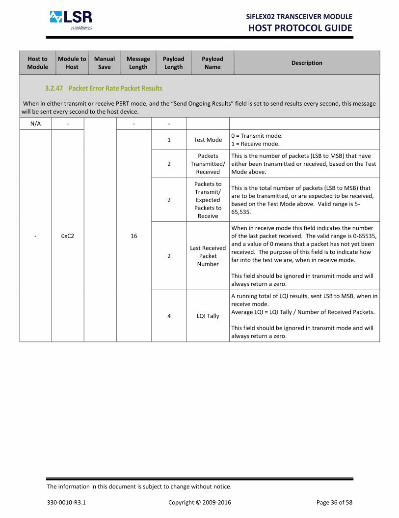
3.2.47 Packet Error Rate Packet Results
When in either transmit or receive PERT mode, and the “Send Ongoing Results” field is set to send results every second, this message will be sent every second to the host device.
N/A -
- -
- 0xC2 16
1 Test Mode 0 = Transmit mode. 1 = Receive mode.
2 Packets
Transmitted/ Received
This is the number of packets (LSB to MSB) that have either been transmitted or received, based on the Test Mode above.
2
Packets to Transmit/ Expected
Packets to Receive
This is the total number of packets (LSB to MSB) that are to be transmitted, or are expected to be received, based on the Test Mode above. Valid range is 5-65,535.
2 Last Received
Packet Number
When in receive mode this field indicates the number of the last packet received. The valid range is 0-65535, and a value of 0 means that a packet has not yet been received. The purpose of this field is to indicate how far into the test we are, when in receive mode. This field should be ignored in transmit mode and will always return a zero.
4 LQI Tally
A running total of LQI results, sent LSB to MSB, when in receive mode. Average LQI = LQI Tally / Number of Received Packets. This field should be ignored in transmit mode and will always return a zero.

SiFLEX02 TRANSCEIVER MODULE
HOST PROTOCOL GUIDE
The information in this document is subject to change without notice. 330-0010-R3.1 Copyright © 2009-2016 Page 37 of 58
Host to Module
Module to Host
Manual Save
Message Length
Payload Length
Payload Name
Description
3.2.48 Set/Query Packet Error Rate Test Status
This message is used to stop a test in progress and/or query the test status.
0x43 -
6 1 Cancel Test This value if set to 1 will result in cancelling a test in progress, and if set to 0 will not affect the current state of the test.
- 0xC3 17
1 Test Status 0 = Packet error rate test is not in progress. 1 = Packet error rate test is in progress
1 Test Mode 0 = Transmit mode. 1 = Receive mode.
2 Packets
Transmitted/ Received
This is the number of packets (LSB to MSB) that have either been transmitted or received, based on the Test Mode above.
2
Packets to Transmit/ Expected
Packets to Receive
This is the total number of packets (LSB to MSB) that are to be transmitted, or are expected to be received, based on the Test Mode above. Valid range is 5-65,535.
2 Last Received
Packet Number
When in receive mode this field indicates the number of the last packet received. The valid range is 0-65535, and a value of 0 means that a packet has not yet been received. The purpose of this field is to indicate how far into the test we are, when in receive mode. This field should be ignored in transmit mode and will always return a zero.
4 LQI Tally A running total of LQI results sent LSB to MSB. Average LQI = LQI Tally / Number of Received Packets.

SiFLEX02 TRANSCEIVER MODULE
HOST PROTOCOL GUIDE
The information in this document is subject to change without notice. 330-0010-R3.1 Copyright © 2009-2016 Page 38 of 58
Host to Module
Module to Host
Manual Save
Message Length
Payload Length
Payload Name
Description
3.2.49 Channel Energy Scan
0x44 -
8
2 Channel Mask
Two byte bitmask (LSB to MSB) of the RF channels to perform an energy scan on. The least significant bit corresponds to channel 1 and goes up bit by bit until channel 10.
1 Scan Duration
The time to scan each channel (0 – 14).
Duration Time
0 61.4 mS
1 92.2 mS
2 154 mS
3 276 mS
4 522 mS
5 1.01 S
6 2.00 S
7 3.96 S
8 7.90 S
9 15.8 S
10 31.5 S
11 62.9 S
12 126 S
13 252 S
14 503 S
- 0xC4 5 -
3.2.50 Channel Energy Scan Response
N/A -
- -
- 0xC5 17
2 Channel Mask
Two byte bitmask (LSB to MSB) of the RF channels the energy scan was performed on. The least significant bit corresponds to channel 1 and goes up bit by bit until channel 10.
10 Energy Levels
List
List of energy levels that consists of one byte for each channel representing the RF energy level that was measured. The order of the list starts with channel 1 and goes up to channel 10. Note that channels not scanned are returned in the list.

SiFLEX02 TRANSCEIVER MODULE
HOST PROTOCOL GUIDE
The information in this document is subject to change without notice. 330-0010-R3.1 Copyright © 2009-2016 Page 39 of 58
Host to Module
Module to Host
Manual Save
Message Length
Payload Length
Payload Name
Description
3.2.51 Calibrate ADC Reference
0x46 -
7 2 Supply Voltage
The Supply Voltage in millivolts (LSB to MSB). For example a supply voltage of 3.311V will be passed as 33111. ***Note: This command is for production use only. Users should not issue this command to the module.
- 0xC6 5 -
3.2.52 Start RF Range Test
Note: Sending this message will start or restart the range test, and clear all statistics
0x47 -
10
1 Test Mode 0 = Device is a slave (address = 200) 1 = Device is a master (address = 100)
1 Master Options
Bitmask of range test mode options. Bit 0: 802.15.4 Retries/Acks (0 = disable, 1 = enable) Bit 1: Request Application Ack (0 = disable, 1 = enable)
1 Channel The RF channel that the transceiver operates on (1-10).
2 Reserved Reserved for future use. Set to 0.
- 0xC7 5 -

SiFLEX02 TRANSCEIVER MODULE
HOST PROTOCOL GUIDE
The information in this document is subject to change without notice. 330-0010-R3.1 Copyright © 2009-2016 Page 40 of 58
Host to Module
Module to Host
Manual Save
Message Length
Payload Length
Payload Name
Description
3.2.53 Query RF Range Test Results – Slave Device
0x48 - 5 -
- 0xC8 19
2 First Packet
ID from Master
This is the packet ID (LSB to MSB) of the first received packet. Valid range is 0-65,535.
2 Last Packet
ID from Master
This is the packet ID (LSB to MSB) of the last received packet. Valid range is 0-65,535.
2 Slave Packet
Count This is the number of packets received by the slave (LSB to MSB)
2 Slave Battery
Voltage
This is the last stored battery voltage of the slave device in mV. (i.e. a value of 3000 = 3000mV or 3.0V).
2 Master Battery Voltage
This is the last reported battery voltage of the master device in mV. (i.e. a value of 3000 = 3000mV or 3.0V).
4 Reserved Reserved for future use. Set to 0.
SiFLEX02 TRANSCEIVER MODULE
HOST PROTOCOL GUIDE
The information in this document is subject to change without notice. 330-0010-R3.1 Copyright © 2009-2016 Page 41 of 58
Host to Module
Module to Host
Manual Save
Message Length
Payload Length
Payload Name
Description
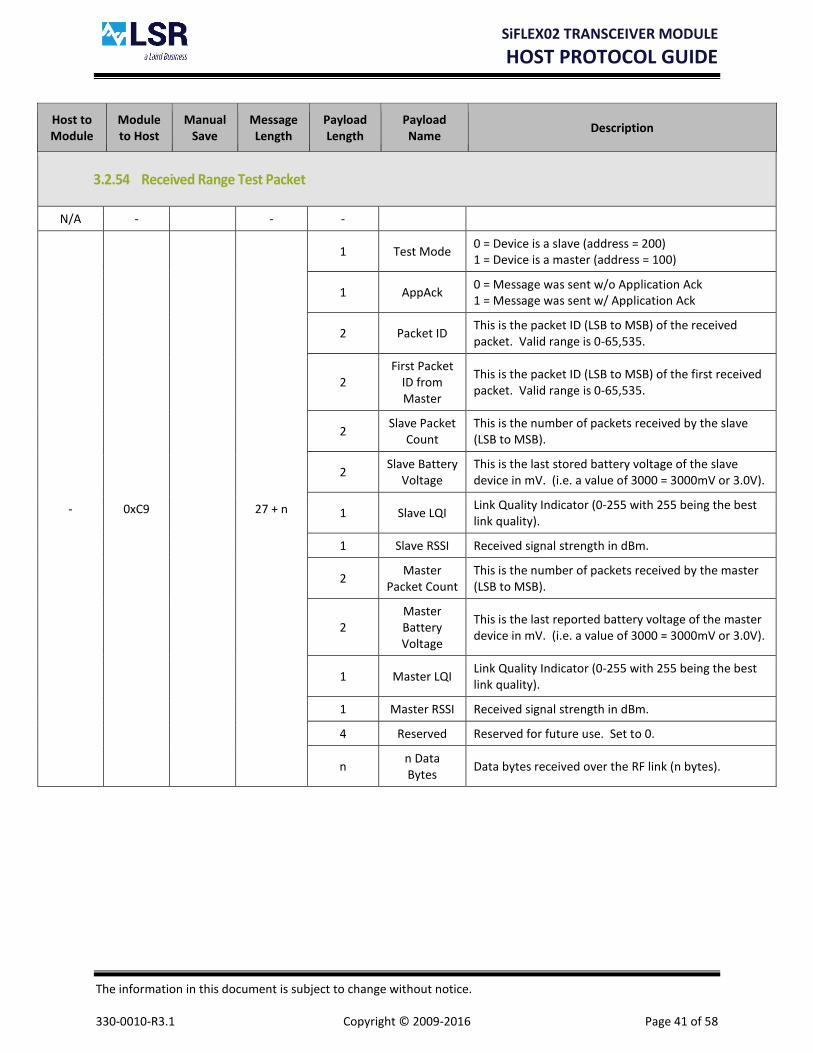
3.2.54 Received Range Test Packet
N/A - - -
- 0xC9 27 + n
1 Test Mode 0 = Device is a slave (address = 200) 1 = Device is a master (address = 100)
1 AppAck 0 = Message was sent w/o Application Ack 1 = Message was sent w/ Application Ack
2 Packet ID This is the packet ID (LSB to MSB) of the received packet. Valid range is 0-65,535.
2 First Packet
ID from Master
This is the packet ID (LSB to MSB) of the first received packet. Valid range is 0-65,535.
2 Slave Packet
Count This is the number of packets received by the slave (LSB to MSB).
2 Slave Battery
Voltage This is the last stored battery voltage of the slave device in mV. (i.e. a value of 3000 = 3000mV or 3.0V).
1 Slave LQI Link Quality Indicator (0-255 with 255 being the best link quality).
1 Slave RSSI Received signal strength in dBm.
2 Master
Packet Count This is the number of packets received by the master (LSB to MSB).
2 Master Battery Voltage
This is the last reported battery voltage of the master device in mV. (i.e. a value of 3000 = 3000mV or 3.0V).
1 Master LQI Link Quality Indicator (0-255 with 255 being the best link quality).
1 Master RSSI Received signal strength in dBm.
4 Reserved Reserved for future use. Set to 0.
n n Data Bytes
Data bytes received over the RF link (n bytes).

SiFLEX02 TRANSCEIVER MODULE
HOST PROTOCOL GUIDE
The information in this document is subject to change without notice. 330-0010-R3.1 Copyright © 2009-2016 Page 42 of 58
Host to Module
Module to Host
Manual Save
Message Length
Payload Length
Payload Name
Description
3.2.55 Repeater Test Mode – For Internal Use Only
0x4D -
10 1 Options
Bitmask of repeater test mode options. Bit 0: Ignore messages from our device address minus one. (0 = disable, 1 = enable).
4 Reserved Reserved for future use. Set to 0.
- 0xCD 5 -
3.2.56 Enable/Disable Terminal Debug Messages – For Internal Use Only
0x4E -
7 1 Options
Bitmask of the terminal messages options. Bit 0: Repeater Diagnostics (0 = disable, 1 = enable)
1 Reserved Reserved for future use. Set to 0.
- 0xCE 5 -
3.2.57 Terminal Debug Message – For Internal Use Only
N/A -
- 0xCF 5+n n ASCII Message String of ASCII characters to display in terminal window.
3.2.58 Set Host Interface Configuration
0x50 - X
16
1 Options Bitmask of host interface options. Bit 0: Enable CTS Functionality (0 = disable, 1 = enable).
1 Min Packet
Spacing
This is the spacing between outgoing host packets (from module to host) in 200usec increments (LSB to MSB), from 0 to 51msec. Zero is no spacing. Example: a value of 10 would put approximately 2msec between outgoing packets.
9 Reserved Reserved for future use. Set to 0.
- 0xD0 5 -

SiFLEX02 TRANSCEIVER MODULE
HOST PROTOCOL GUIDE
The information in this document is subject to change without notice. 330-0010-R3.1 Copyright © 2009-2016 Page 43 of 58
Host to Module
Module to Host
Manual Save
Message Length
Payload Length
Payload Name
Description
3.2.59 Query Host Interface Configuration
0x51 -
5 -
0xD1 16
1 Options Bitmask of host interface options. Bit 0: Enable CTS Functionality (0 = disable, 1 = enable).
1 Min Packet
Spacing
This is the spacing between outgoing host packets (from module to host) in 200usec increments (LSB to MSB), from 0 to 51msec. Zero is no spacing. Example: a value of 10 would put approximately 2msec between outgoing packets.
9 Reserved Reserved for future use. Set to 0.
SiFLEX02 TRANSCEIVER MODULE
HOST PROTOCOL GUIDE
The information in this document is subject to change without notice. 330-0010-R3.1 Copyright © 2009-2016 Page 44 of 58
Host to Module
Module to Host
Manual Save
Message Length
Payload Length
Payload Name
Description
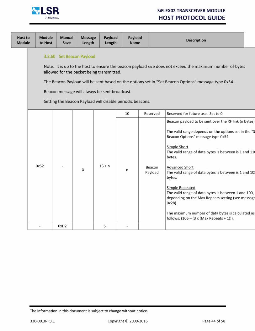
3.2.60 Set Beacon Payload
Note: It is up to the host to ensure the beacon payload size does not exceed the maximum number of bytes allowed for the packet being transmitted.
The Beacon Payload will be sent based on the options set in “Set Beacon Options” message type 0x54.
Beacon message will always be sent broadcast.
Setting the Beacon Payload will disable periodic beacons.
0x52 - X
15 + n
10 Reserved Reserved for future use. Set to 0.
n Beacon Payload
Beacon payload to be sent over the RF link (n bytes) The valid range depends on the options set in the “Set Beacon Options” message type 0x54. Simple Short The valid range of data bytes is between is 1 and 110 bytes. Advanced Short The valid range of data bytes is between is 1 and 108 bytes. Simple Repeated The valid range of data bytes is between 1 and 100, depending on the Max Repeats setting (see message 0x28). The maximum number of data bytes is calculated as follows: (106 – (3 x (Max Repeats + 1))).
- 0xD2 5 -

SiFLEX02 TRANSCEIVER MODULE
HOST PROTOCOL GUIDE
The information in this document is subject to change without notice. 330-0010-R3.1 Copyright © 2009-2016 Page 45 of 58
Host to Module
Module to Host
Manual Save
Message Length
Payload Length
Payload Name
Description
3.2.61 Query Beacon Payload
0x53 -
5 -
- 0xD3 15 + n
10 Reserved Reserved for future use. Set to 0.
n Beacon Payload
Beacon payload to be sent over the RF link (n bytes) The valid range depends on the options set in the “Set Beacon Options” message type 0x53. Simple Short The valid range of data bytes is between is 1 and 110 bytes. Advanced Short The valid range of data bytes is between is 1 and 108 bytes. Simple Repeated The valid range of data bytes is between 1 and 100, depending on the Max Repeats setting (see message 0x28). The maximum number of data bytes is calculated as follows: (106 – (3 x (Max Repeats + 1))).

SiFLEX02 TRANSCEIVER MODULE
HOST PROTOCOL GUIDE
The information in this document is subject to change without notice. 330-0010-R3.1 Copyright © 2009-2016 Page 46 of 58
Host to Module
Module to Host
Manual Save
Message Length
Payload Length
Payload Name
Description
3.2.62 Set Beacon Options
Note: Issuing this command to the module will disable periodic beacons. If the command is valid and beacons are requested to be enabled, the periodic beacons will be restarted.
0x54 - X
19
1 Options
Enable transmission of a periodic beacon. Bit 0 = Enable Beacon (0 = Not Enabled, 1 = Enabled) Bit 1 = Send Host Ack on Beacon Tx (0 = Not Enabled, 1 = Enabled) Bit 2 = Toggle Module Pin 15 on Beacon Tx (0 = Not Enabled, 1 = Enabled) Bit 3 = Toggle Module Pin 15 on Beacon Rx (0 = Not Enabled, 1 = Enabled)
1 RF Msg Type
of Beacon
0x00 = Simple Short 0x01 = Advanced Short 0x02 = Simple Repeated Note: Advanced Short messages will always be sent to the broadcast PAN.
2 Beacon Header
This is the Header that will be appended to the front of the beacon payload (LSB to MSB). As such these bytes appear as the first two bytes in the payload field of the RF Msg Type being used for the beacon.
2 Beacon Interval
This is the interval between outgoing beacon packets in 50mS increments (LSB to MSB). Example: a value of 10 would put approximately 500mS between outgoing packets. Range = 1 to 65,535 (50mS to 54.6 minutes). Note: A beacon will not be sent out unless the beacon payload has been setup (Message type 0x52).
8 Reserved Reserved for future use. Set to 0.
- 0xD4 5 -

SiFLEX02 TRANSCEIVER MODULE
HOST PROTOCOL GUIDE
The information in this document is subject to change without notice. 330-0010-R3.1 Copyright © 2009-2016 Page 47 of 58
Host to Module
Module to Host
Manual Save
Message Length
Payload Length
Payload Name
Description
3.2.63 Query Beacon Options
0x55 -
5 -
- 0xD5 19
1 Options
Enable transmission of a periodic beacon. Bit 0 = Enable Beacon (0 = Not Enabled, 1 = Enabled) Bit 1 = Send Host Ack on Beacon Tx (0 = Not Enabled, 1 = Enabled) Bit 2 = Toggle Module Pin 15 on Beacon Tx (0 = Not Enabled, 1 = Enabled) Bit 3 = Toggle Module Pin 15 on Beacon Rx (0 = Not Enabled, 1 = Enabled)
1 RF Msg Type
of Beacon
0x00 = Simple Short 0x01 = Advanced Short 0x02 = Simple Repeated Note: Advanced Short messages will always be sent to the broadcast PAN.
2 Beacon Header
This is the Header that will be appended to the front of the beacon payload (LSB to MSB). As such these bytes appear as the first two bytes in the payload field of the RF Msg Type being used for the beacon.
2 Beacon Interval
This is the interval between outgoing beacon packets in 50mS increments (LSB to MSB). Example: a value of 10 would put approximately 500mS between outgoing packets. Range = 1 to 65,535 (50mS to 54.6 minutes). Note: A beacon will not be sent out unless the beacon payload has been setup (Message type 0x52)
8 Reserved Reserved for future use. Set to 0.

SiFLEX02 TRANSCEIVER MODULE
HOST PROTOCOL GUIDE
The information in this document is subject to change without notice. 330-0010-R3.1 Copyright © 2009-2016 Page 48 of 58
Host to Module
Module to Host
Manual Save
Message Length
Payload Length
Payload Name
Description
3.2.64 Beacon Message Transmit Host Ack
This message will be sent after a device transmits a beacon message if enabled in “Set Beacon Options” message type 0x54.
- -
- -
- 0xD6 14 1 Status
0x00 = Failure to transmit beacon. 0x01 = Beacon successfully transmitted.
8 Reserved Reserved for future use. Set to 0.
Table 3 Host Protocol Message Definitions

SiFLEX02 TRANSCEIVER MODULE
HOST PROTOCOL GUIDE
The information in this document is subject to change without notice. 330-0010-R3.1 Copyright © 2009-2016 Page 49 of 58
4 Appendix A – Host Protocol Quick Start
4.1 Overview
The Host Protocol consists of a superset of commands to support a large variety of applications. Typical applications only require several commands to get up and running. This section will take you through configuring a pair of modules and sending and receiving RF messages between those modules.
4.2 Configure and Save Settings
The Host Protocol command 0x10 Set Basic RF Settings (section 3.2.15) can be used to configure all the primary settings.
4.2.1 PAN ID
The PAN ID or Personal Area Network ID is a 16-bit value used to distinguish networks from one another. All devices within a network should have the PAN ID configured the same. For this example the PAN ID will be set to 100 (0x0064).
4.2.2 Short/Long Addressing
Note that while the module supports both short and long addresses, only one address mode is allowed at any time. For example, a module can be configured with a short address of 0x0001, and a long address of 0x0000000000000001, however in this case only the short address applies. The reason for this is that in order to use the long address, the short address would need to be configured to 65,535 (0xFFFF). A module will only be able to send or receive RF messages using the same addressing mode the module is configured with.
4.2.2.1 Short Transceiver Address
The Short Transceiver Address is a 16-bit value used to identify a particular device. This address should be unique for each device in the network. The valid range of short addresses is 0 to 65,534 (0xFFFE). For this example the short addresses will be set to 1 (0x0001) and 2 (0x0002) on the two modules.

SiFLEX02 TRANSCEIVER MODULE
HOST PROTOCOL GUIDE
The information in this document is subject to change without notice. 330-0010-R3.1 Copyright © 2009-2016 Page 50 of 58
4.2.2.2 Long Transceiver Address
The Long Transceiver Address is a 64-bit value used to identify a particular device. In order to configure the module to use the long address, the short address must be set to 65,535 (0xFFFF). The long address should be unique for each device in the network. The valid range of long addresses is 0x0000000000000001 to 0xFFFFFFFFFFFFFFFE. For this example the long addresses are not used.
4.2.3 RF Channel
The RF Channel is used to configure on what frequency the module will communicate. All devices within a network should have the RF Channel configured the same. For this example the RF Channel will be set to 5, which equates to a center frequency of 914Mhz.
4.2.4 RF Power Level
The RF Power Level is used to configure the transmit power of the module. A low setting (0) will minimize the distance the module can transmit, while a high setting (21) will maximize the transmit distance. In most cases all devices within a network should have the RF Power Level configured the same. For this example the RF Power Level will be set to its maximum setting of 21, which equates to a output power of +24dbm (250mW).
4.2.5 Receive Filters
Broadcast messages are used to send messages to a group of devices. These groups could be all devices on the same PAN, or all devices on the same channel. The receive filters is a bitmask used to enable or disable the specific filters.
4.2.5.1 Allow Broadcast Address
The Allow Broadcast Address filter when set will allow the module to receive a message broadcast to all addresses on the same PAN ID.
4.2.5.2 Allow Broadcast PAN
The Allow Broadcast PAN filter when set will allow the module to receive a message broadcast to all PAN ID’s.
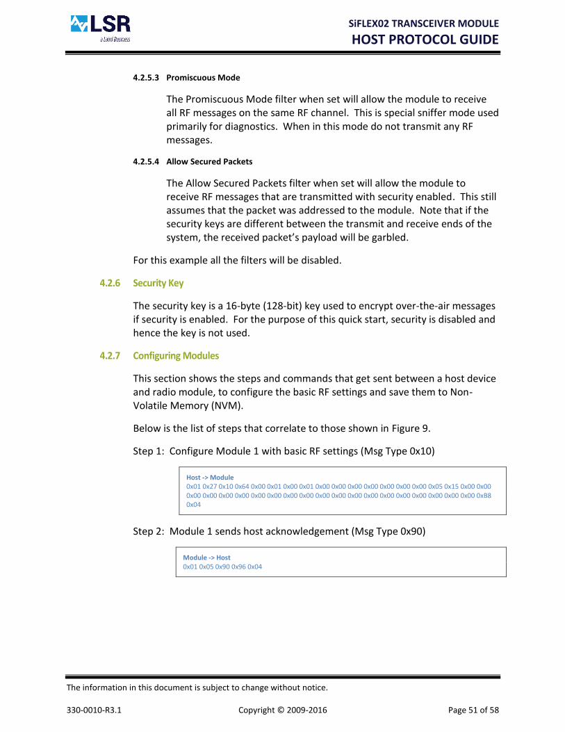
SiFLEX02 TRANSCEIVER MODULE
HOST PROTOCOL GUIDE
The information in this document is subject to change without notice. 330-0010-R3.1 Copyright © 2009-2016 Page 51 of 58
4.2.5.3 Promiscuous Mode
The Promiscuous Mode filter when set will allow the module to receive all RF messages on the same RF channel. This is special sniffer mode used primarily for diagnostics. When in this mode do not transmit any RF messages.
4.2.5.4 Allow Secured Packets
The Allow Secured Packets filter when set will allow the module to receive RF messages that are transmitted with security enabled. This still assumes that the packet was addressed to the module. Note that if the security keys are different between the transmit and receive ends of the system, the received packet’s payload will be garbled.
For this example all the filters will be disabled.
4.2.6 Security Key
The security key is a 16-byte (128-bit) key used to encrypt over-the-air messages if security is enabled. For the purpose of this quick start, security is disabled and hence the key is not used.
4.2.7 Configuring Modules
This section shows the steps and commands that get sent between a host device and radio module, to configure the basic RF settings and save them to Non-Volatile Memory (NVM).
Below is the list of steps that correlate to those shown in Figure 9.
Step 1: Configure Module 1 with basic RF settings (Msg Type 0x10)
Host -> Module 0x01 0x27 0x10 0x64 0x00 0x01 0x00 0x01 0x00 0x00 0x00 0x00 0x00 0x00 0x00 0x05 0x15 0x00 0x00 0x00 0x00 0x00 0x00 0x00 0x00 0x00 0x00 0x00 0x00 0x00 0x00 0x00 0x00 0x00 0x00 0x00 0x00 0xB8 0x04
Step 2: Module 1 sends host acknowledgement (Msg Type 0x90)
Module -> Host 0x01 0x05 0x90 0x96 0x04

SiFLEX02 TRANSCEIVER MODULE
HOST PROTOCOL GUIDE
The information in this document is subject to change without notice. 330-0010-R3.1 Copyright © 2009-2016 Page 52 of 58
Step 3: Save basic RF settings in Module 1 to NVM (Msg Type 0x12)
Host -> Module 0x01 0x05 0x12 0x18 0x04
Step 4: Module 1 sends host acknowledgement (Msg Type 0x92)
Module -> Host 0x01 0x05 0x92 0x98 0x04
Step 5: Configure Module 2 with basic RF settings (Msg Type 0x10)
Host -> Module 0x01 0x27 0x10 0x64 0x00 0x02 0x00 0x02 0x00 0x00 0x00 0x00 0x00 0x00 0x00 0x05 0x15 0x00 0x00 0x00 0x00 0x00 0x00 0x00 0x00 0x00 0x00 0x00 0x00 0x00 0x00 0x00 0x00 0x00 0x00 0x00 0x00 0xBA 0x04
Step 6: Module 2 sends host acknowledgement (Msg Type 0x90)
Module -> Host 0x01 0x05 0x90 0x96 0x04
Step 7: Save basic RF settings in Module 2 to NVM (Msg Type 0x12)
Host -> Module 0x01 0x05 0x12 0x18 0x04
Step 8: Module 2 sends host acknowledgement (Msg Type 0x92)
Module -> Host 0x01 0x05 0x92 0x98 0x04

SiFLEX02 TRANSCEIVER MODULE
HOST PROTOCOL GUIDE
The information in this document is subject to change without notice. 330-0010-R3.1 Copyright © 2009-2016 Page 53 of 58
Host
Processor
Device 1 - Transmitter
Radio
Module
Msg Type: 0x10
Set Basic RF Settings
Msg Type: 0x90
Set Basic RF Settings Ack
Msg Type: 0x12
Save Settings To NV Memory
Msg Type: 0x92
Save Settings To NV Memory Ack
Host
Processor
Device 2 - Receiver
Radio
Module
Msg Type: 0x10
Set Basic RF Settings
Msg Type: 0x90
Set Basic RF Settings Ack
Msg Type: 0x12
Save Settings To NV Memory
Msg Type: 0x92
Save Settings To NV Memory Ack
Step 1
Step 2
Step 3
Step 4
Step 5
Step 6
Step 7
Step 8
Figure 9 – Module Configuration

SiFLEX02 TRANSCEIVER MODULE
HOST PROTOCOL GUIDE
The information in this document is subject to change without notice. 330-0010-R3.1 Copyright © 2009-2016 Page 54 of 58
4.2.8 Send/Receive RF Messages without ACK
This section shows the steps and commands that get sent between a host device and radio module, to send and receive data over-the-air (OTA) using CCA without RF acks and retries or security. In the example below the data sent is ASCII 1234567890, and the packet id is 1.
Below is the list of steps that correlate to those shown in Figure 10.
Step 1: Command Module 1 to send OTA data (Msg Type 0x20)
Host1 -> Module1 01 13 20 00 02 00 01 31 32 33 34 35 36 37 38 39 30 44 04
Step 2: Module 1 sends data OTA
Step 3: Module 1 sends host acknowledgement (Msg Type 0xA0)
Module1 -> Host1 01 07 A0 01 01 AA 04
Step 4: Module 2 receives the OTA message and sends it to the host (Msg Type 0xA1)
Module2 -> Host2 01 1B A1 00 00 00 00 00 00 FF 02 00 01 00 01 31 32 33 34 35 36 37 38 39 30 CD 04
Host
Processor
Device 1 - Transmitter
Radio
Module
Radio
Module
Device 2 - Receiver
Host
Processor
Msg Type: 0x20
Send Simple Short RF Packet
Msg Type: 0xA0
Send Simple Short RF Packet Ack
OTA Packet
Msg Type: 0xA1
Received Simple Short RF Packet
Step 1
Step 2
Step 3
Step 4
Figure 10 Send/Receive RF Message without RF Acks

SiFLEX02 TRANSCEIVER MODULE
HOST PROTOCOL GUIDE
The information in this document is subject to change without notice. 330-0010-R3.1 Copyright © 2009-2016 Page 55 of 58
4.2.9 Send/Receive RF Messages with ACK
This section shows the steps and commands that get sent between a host device and radio module, to send and receive data OTA with CCA enabled, using RF acks and retries, and once again no security. In the example below the data sent is ASCII 1234567890, and the packet id is 1.
Below is the list of steps that correlate to those shown in Figure 11.
Step 1: Command Module 1 to send OTA data (Msg Type 0x20)
Host1 -> Module1 01 13 20 01 02 00 01 31 32 33 34 35 36 37 38 39 30 45 04
Step 2: Module 1 sends data OTA
Step 3: Module 2 sends a RF acknowledgement back to Module 1.
Step 4: Module 2 receives the OTA message and sends it to the host (Msg Type 0xA1)
Module2 -> Host2 01 1B A1 00 00 00 00 00 00 FF 02 00 01 00 01 31 32 33 34 35 36 37 38 39 30 CD 04
Step 5: Module 1 sends host acknowledgement (Msg Type 0xA0)
Module1 -> Host1 01 07 A0 01 01 AA 04

SiFLEX02 TRANSCEIVER MODULE
HOST PROTOCOL GUIDE
The information in this document is subject to change without notice. 330-0010-R3.1 Copyright © 2009-2016 Page 56 of 58
Host
Processor
Device 1 - Transmitter
Radio
Module
Radio
Module
Device 2 - Receiver
Host
Processor
Msg Type: 0x20
Send Simple Short RF Packet
Msg Type: 0xA0
Send Simple Short RF Packet Ack
OTA Packet
Msg Type: 0xA1
Received Simple Short RF Packet
OTA Ack
Step 1
Step 2
Step 3
Step 5
Step 4
Figure 11 Send/Receive RF Message with RF Acks

SiFLEX02 TRANSCEIVER MODULE
HOST PROTOCOL GUIDE
The information in this document is subject to change without notice. 330-0010-R3.1 Copyright © 2009-2016 Page 57 of 58
5 Contacting LS Research
Headquarters LS Research, LLC W66 N220 Commerce Court Cedarburg, WI 53012-2636 USA Tel: 1(262) 375-4400 Fax: 1(262) 375-4248
Website www.lsr.com
Wiki wiki.lsr.com
Technical Support forum.lsr.com
Sales Contact [email protected]
The information in this document is provided in connection with LS Research (hereafter referred to as “LSR”) products. No license, express or implied, by estoppel or otherwise, to any intellectual property right is granted by this document or in connection with the sale of LSR products. EXCEPT AS SET FORTH IN LSR’S TERMS AND CONDITIONS OF SALE LOCATED ON LSR’S WEB SITE, LSR ASSUMES NO LIABILITY WHATSOEVER AND DISCLAIMS ANY EXPRESS, IMPLIED OR STATUTORY WARRANTY RELATING TO ITS PRODUCTS INCLUDING, BUT NOT LIMITED TO, THE IMPLIED WARRANTY OF MERCHANTABILITY, FITNESS FOR A PARTICULAR PURPOSE, OR NON-INFRINGEMENT. IN NO EVENT SHALL LSR BE LIABLE FOR ANY DIRECT, INDIRECT, CONSEQUENTIAL, PUNITIVE, SPECIAL OR INCIDENTAL DAMAGES (INCLUDING, WITHOUT LIMITATION, DAMAGES FOR LOSS OF PROFITS, BUSINESS INTERRUPTION, OR LOSS OF INFORMATION) ARISING OUT OF THE USE OR INABILITY TO USE THIS DOCUMENT, EVEN IF LSR HAS BEEN ADVISED OF THE POSSIBILITY OF SUCH DAMAGES. LSR makes no representations or warranties with respect to the accuracy or completeness of the contents of this document and reserves the right to make changes to specifications and product descriptions at any time without notice. LSR does not make any commitment to update the information contained herein. Unless specifically provided otherwise, LSR products are

SiFLEX02 TRANSCEIVER MODULE
HOST PROTOCOL GUIDE
The information in this document is subject to change without notice. 330-0010-R3.1 Copyright © 2009-2016 Page 58 of 58
not suitable for, and shall not be used in, automotive applications. LSR’s products are not intended, authorized, or warranted for use as components in applications intended to support or sustain life.