Embed Size (px)
Citation preview
Siemens TCP/IP Ethernet Driver
© 2019 PTC Inc. All Rights Reserved.
Siemens TCP/IP Ethernet Driver
Table of Contents
Siemens TCP/IP Ethernet Driver 1
Table of Contents 2
Siemens TCP/IP Ethernet Driver 5
Overview 5
Setup 5
Channel Properties — General 6
Channel Properties — Ethernet Communications 7
Channel Properties — Write Optimizations 7
Channel Properties — Advanced 8
Device Properties — Identification 9
Operating Mode 9
Device Properties — ScanMode 10
Device Properties — Timing 11
Device Properties — Auto-Demotion 12
Device Properties — Tag Generation 12
Device Properties — Communications Parameters 14
Device Properties — S7 Communication Parameters 15
S7-300/400/1200/1500 16
Device Properties — Addressing Options 16
Device Properties — Tag Import 18
Device Properties — Redundancy 19
Channel Configuration API Commands 19
Siemens TCP/IP Ethernet Channel Setup with API Commands 20
Device Configuration API Commands 20
Siemens TCP/IP Ethernet Device Setup with API Commands 21
Siemens TCP/IP Ethernet API Example 23
Optimizing Communications 24
Data Types Description 25
Address Descriptions 25
S7-200 Address Descriptions 26
S7-300 Address Descriptions 28
S7-400 Address Descriptions 29
S7-1200 Address Descriptions 29
S7-1500 Address Descriptions 29
NetLink: S7-300 Address Descriptions 30
NetLink: S7-400 Address Descriptions 30
www.ptc.com
2

Siemens TCP/IP Ethernet Driver
Internal Tags 30
Standard S7-300/400/1200/1500 Item Syntax 31
Legacy S7-300/400 Item Syntax 37
Event Log Messages 45
Reason = 'Frame contains errors'. 45
Reason = 'Device returned transport error'. Error code = <error>. 45
Reason = 'Device returned protocol error'. Error class = <class>, Error code = <error>. 46
Reason = 'Device returned data access error'. Error code = <error>. 46
Reason = 'Device is not responding'. 46
Reason = 'Unknown error occurred'. 47
Reason = NetLink returned error. Error code = <error>. 47
Failed to resolve host. | Host = '<host name>'. 48
Auto-generated tag names and descriptions may not appear as expected due to string conversionerror. 48
A required code page is unavailable on this machine. Tag generationmay fail or tag names anddescriptions may not appear as expected. | Required code page = <page>. 48
Unable to load the Step 7 language file. 49
Memory exception reading the Step 7 language file. 49
Step 7 language file failed to open. | OS error = '<error>'. 49
Tag generation failure. | Data block name = '<block name>', data block number = <block num-ber>. 50
Created tag in group due to internal block size. | Tag address = '<address>', tag name ='<name>', group name = '<name>'. 50
Tag not created because arrays are not supported with specified data type. | Tag name ='<name>', group name = '<name>', data type = '<type>'. 50
Unable to connect to device. | 51
Unable to establish association with device. | 51
Unable to read from address on device. | Address = '<address>', 52
Unable to read from address on device. Tag deactivated. | Address = '<address>', 53
Unable to read data from device. | Data block = '<block>', block start = <address>, block size =<size>, 53
Unable to read data from device. Block deactivated. | Data block = '<block>', block start =<address>, block size = <size>, 54
Unable to read data from device. | Memory type = '<type>', block start = <address>, block size =<size> (bytes), 55
Unable to read data from device. Block deactivated. | Memory type = '<type>', block start =<address>, block size = <size> (bytes), 56
Unable to write to address on device. | Address = '<address>', 57
Unable to write to address on device. HEXSTRING length is different from tag length. | Address ='<address>', HEXSTRING length = <length> (bytes), tag length = <length> (bytes). 58
Unable to write to address on device. HEXSTRING contains a non-hexadecimal character. | 58
www.ptc.com
3
Siemens TCP/IP Ethernet Driver
Address = '<address>'.
Unable to write to address on device. HEXSTRING length must be an even number of characters.| Address = '<address>'. 58
Unable to write to address on device. Time of Day string contains a syntax error. Expected 'hh:m-m:ss.hhh' format. | Address = '<address>', Time of Day string = '<string>'. 59
Error Codes 59
Appendix: Configuring Siemens Connections 61
How To Configure S7-200 Connections in Micro/WIN 61
How To Configure S7-300/400 Connections in STEP 7 76
How To Configure S7-1200 Connections with the Totally Integrated Automation (TIA) Portal 82
How To Configure S7-1500 Connections 85
Appendix: Alternate Syntax Support 87
Applicom Direct-Link Item Syntax 87
INAT OPC Server TCPIPH1 Item Syntax 89
Siemens Simatic Net Item Syntax 93
Siemens STEP 7 Item Syntax 95
Softing S7/S5 OPC Server Item Syntax 98
Index 101
www.ptc.com
4
Siemens TCP/IP Ethernet Driver
Siemens TCP/IP Ethernet DriverHelp version 1.104
CONTENTS
OverviewWhat is the Siemens TCP/IP Ethernet Driver?
Getting StartedHow do I configure a channel and device?
Using the APIHow do I configure a channel and device via the API?
Optimizing CommunicationsHow do I get the best performance from the driver?
Data Types DescriptionWhat data types does this driver support?
Address DescriptionsHow do I address a data location on a Siemens TCP/IP device?
Event Log MessagesWhat messages does the Siemens TCP/IP Ethernet Driver produce?
OverviewThe Siemens TCP/IP Ethernet Driver provides a reliable way to connect Siemens TCP/IP Ethernet devices toOPC client applications, including HMI, SCADA, Historian, MES, ERP, and countless custom applications. It isintended for use with Siemens S7-200, 300, 400, 1200, and 1500 PLCs. There are two options for com-munications:
l Industrial Ethernet TCP/IP interface communication processor (CP). The protocol used is S7 Mes-saging on Industrial Ethernet (ISO 8073 Class 0) over TCP/IP as defined in RFC1006.
l Hilscher's NetLink adapter. Only an MPI port is required. The NetLink adapter does not support theS7-200 model.
The driver requires no special libraries or hardware. A standard Ethernet card is all that is needed.
SetupA maximum of 1024 devices may be defined on a channel.
Supported DevicesS7-200 via CP243S7-300 via CP343S7-400 via CP443S7-1200*S7-1500*S7-300 via NetLinkS7-400 via NetLink
www.ptc.com
5
Siemens TCP/IP Ethernet Driver
*This device has a built-in Ethernet module.
Supported NetLink Cables and GatewaysNT 50-MPINL 50-MPINL-MPI
Note: For NetLink users, NetLink communication parameters (such as IP Address, Subnet Mask, and BaudRate) can be configured using the NetLink Configuration utility. This application is located in the server's Util-ities sub-directory and can be launched using the Start menu shortcut.
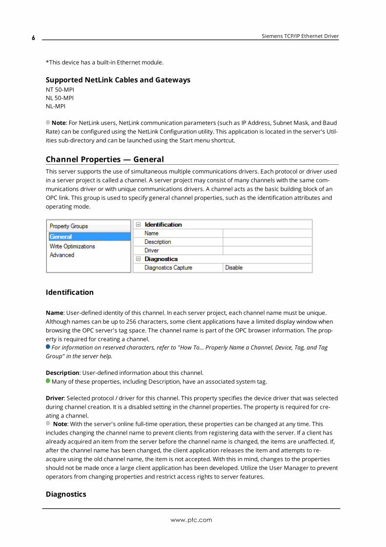
Channel Properties — GeneralThis server supports the use of simultaneous multiple communications drivers. Each protocol or driver usedin a server project is called a channel. A server project may consist of many channels with the same com-munications driver or with unique communications drivers. A channel acts as the basic building block of anOPC link. This group is used to specify general channel properties, such as the identification attributes andoperating mode.
Identification
Name: User-defined identity of this channel. In each server project, each channel name must be unique.Although names can be up to 256 characters, some client applications have a limited display window whenbrowsing the OPC server's tag space. The channel name is part of the OPC browser information. The prop-erty is required for creating a channel.For information on reserved characters, refer to "How To... Properly Name a Channel, Device, Tag, and Tag
Group" in the server help.
Description: User-defined information about this channel. Many of these properties, including Description, have an associated system tag.
Driver: Selected protocol / driver for this channel. This property specifies the device driver that was selectedduring channel creation. It is a disabled setting in the channel properties. The property is required for cre-ating a channel.
Note: With the server's online full-time operation, these properties can be changed at any time. Thisincludes changing the channel name to prevent clients from registering data with the server. If a client hasalready acquired an item from the server before the channel name is changed, the items are unaffected. If,after the channel name has been changed, the client application releases the item and attempts to re-acquire using the old channel name, the item is not accepted. With this in mind, changes to the propertiesshould not be made once a large client application has been developed. Utilize the User Manager to preventoperators from changing properties and restrict access rights to server features.
Diagnostics
www.ptc.com
6
Siemens TCP/IP Ethernet Driver
Diagnostics Capture: When enabled, this optionmakes the channel's diagnostic information available toOPC applications. Because the server's diagnostic features require a minimal amount of overhead pro-cessing, it is recommended that they be utilized when needed and disabled when not. The default is dis-abled.Note: This property is not available if the driver does not support diagnostics.For more information, refer to "Communication Diagnostics" in the server help.
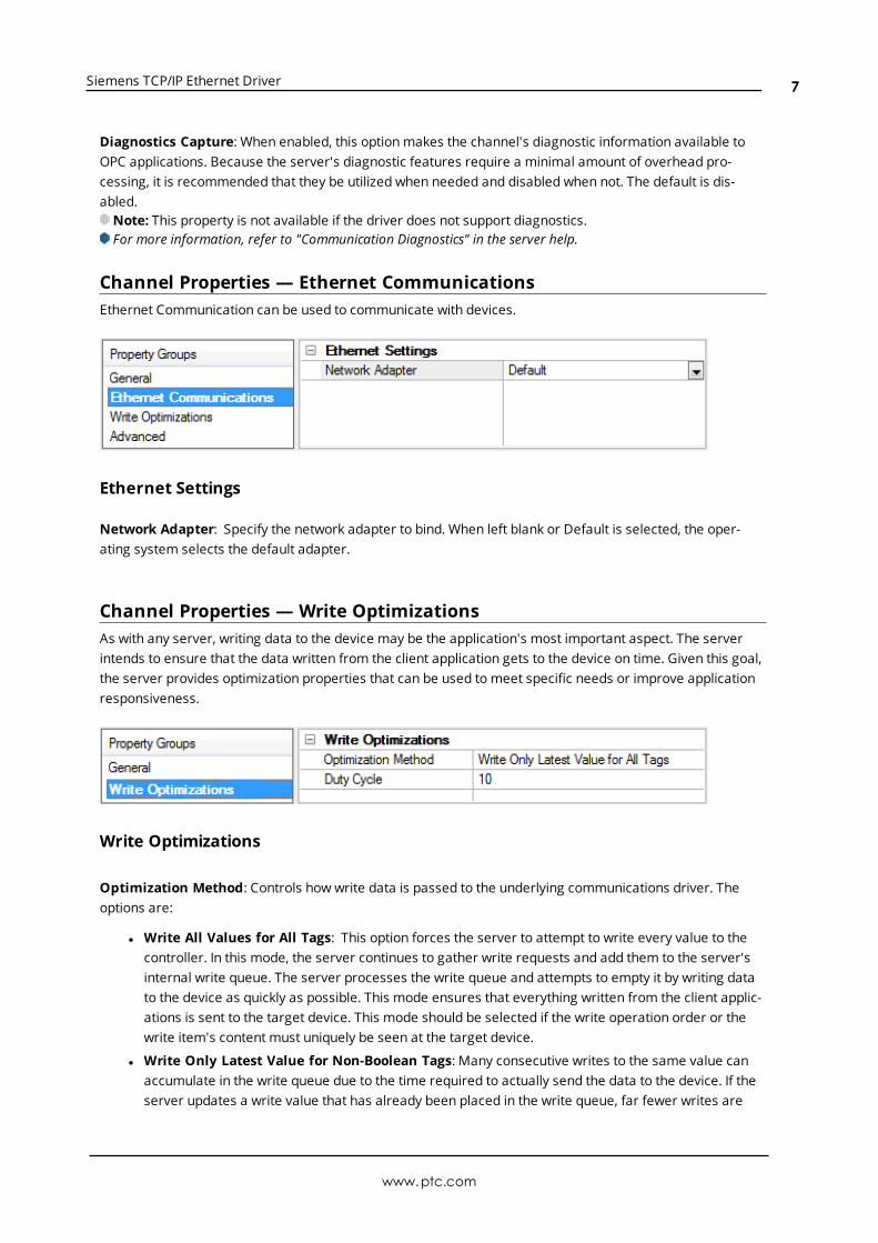
Channel Properties — Ethernet CommunicationsEthernet Communication can be used to communicate with devices.
Ethernet Settings
Network Adapter: Specify the network adapter to bind. When left blank or Default is selected, the oper-ating system selects the default adapter.
Channel Properties — Write OptimizationsAs with any server, writing data to the device may be the application's most important aspect. The serverintends to ensure that the data written from the client application gets to the device on time. Given this goal,the server provides optimization properties that can be used to meet specific needs or improve applicationresponsiveness.
Write Optimizations
Optimization Method: Controls how write data is passed to the underlying communications driver. Theoptions are:
l Write All Values for All Tags: This option forces the server to attempt to write every value to thecontroller. In this mode, the server continues to gather write requests and add them to the server'sinternal write queue. The server processes the write queue and attempts to empty it by writing datato the device as quickly as possible. This mode ensures that everything written from the client applic-ations is sent to the target device. This mode should be selected if the write operation order or thewrite item's content must uniquely be seen at the target device.
l Write Only Latest Value for Non-Boolean Tags: Many consecutive writes to the same value canaccumulate in the write queue due to the time required to actually send the data to the device. If theserver updates a write value that has already been placed in the write queue, far fewer writes are
www.ptc.com
7

Siemens TCP/IP Ethernet Driver
needed to reach the same final output value. In this way, no extra writes accumulate in the server'squeue. When the user stops moving the slide switch, the value in the device is at the correct value atvirtually the same time. As the mode states, any value that is not a Boolean value is updated in theserver's internal write queue and sent to the device at the next possible opportunity. This can greatlyimprove the application performance.Note: This option does not attempt to optimize writes to Boolean values. It allows users to optimize
the operation of HMI data without causing problems with Boolean operations, such as a momentarypush button.
l Write Only Latest Value for All Tags: This option takes the theory behind the second optimizationmode and applies it to all tags. It is especially useful if the application only needs to send the latestvalue to the device. This mode optimizes all writes by updating the tags currently in the write queuebefore they are sent. This is the default mode.
Duty Cycle: is used to control the ratio of write to read operations. The ratio is always based on one read forevery one to ten writes. The duty cycle is set to ten by default, meaning that ten writes occur for each readoperation. Although the application is performing a large number of continuous writes, it must be ensuredthat read data is still given time to process. A setting of one results in one read operation for every writeoperation. If there are no write operations to perform, reads are processed continuously. This allows optim-ization for applications with continuous writes versus a more balanced back and forth data flow.Note: It is recommended that the application be characterized for compatibility with the write optimization
enhancements before being used in a production environment.
Channel Properties — AdvancedThis group is used to specify advanced channel properties. Not all drivers support all properties; so theAdvanced group does not appear for those devices.
Non-Normalized Float Handling: A non-normalized value is defined as Infinity, Not-a-Number (NaN), or asa Denormalized Number. The default is Replace with Zero. Drivers that have native float handling maydefault to Unmodified. Non-normalized float handling allows users to specify how a driver handles non-nor-malized IEEE-754 floating point data. Descriptions of the options are as follows:
l Replace with Zero: This option allows a driver to replace non-normalized IEEE-754 floating point val-ues with zero before being transferred to clients.
l Unmodified: This option allows a driver to transfer IEEE-754 denormalized, normalized, non-num-ber, and infinity values to clients without any conversion or changes.
Note: This property is not available if the driver does not support floating point values or if it only supportsthe option that is displayed. According to the channel's float normalization setting, only real-time driver tags(such as values and arrays) are subject to float normalization. For example, EFM data is not affected by thissetting.
For more information on the floating point values, refer to "How To ... Work with Non-Normalized FloatingPoint Values" in the server help.
www.ptc.com
8
Siemens TCP/IP Ethernet Driver
Inter-Device Delay: Specify the amount of time the communications channel waits to send new requests tothe next device after data is received from the current device on the same channel. Zero (0) disables thedelay.
Note: This property is not available for all drivers, models, and dependent settings.
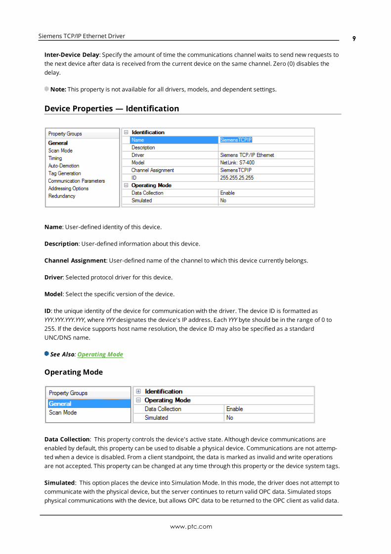
Device Properties — Identification
Name: User-defined identity of this device.
Description: User-defined information about this device.
Channel Assignment: User-defined name of the channel to which this device currently belongs.
Driver: Selected protocol driver for this device.
Model: Select the specific version of the device.
ID: the unique identity of the device for communication with the driver. The device ID is formatted asYYY.YYY.YYY.YYY, where YYY designates the device's IP address. Each YYY byte should be in the range of 0 to255. If the device supports host name resolution, the device ID may also be specified as a standardUNC/DNS name.
See Also: Operating Mode
Operating Mode
Data Collection: This property controls the device's active state. Although device communications areenabled by default, this property can be used to disable a physical device. Communications are not attemp-ted when a device is disabled. From a client standpoint, the data is marked as invalid and write operationsare not accepted. This property can be changed at any time through this property or the device system tags.
Simulated: This option places the device into Simulation Mode. In this mode, the driver does not attempt tocommunicate with the physical device, but the server continues to return valid OPC data. Simulated stopsphysical communications with the device, but allows OPC data to be returned to the OPC client as valid data.
www.ptc.com
9
Siemens TCP/IP Ethernet Driver
While in Simulation Mode, the server treats all device data as reflective: whatever is written to the simulateddevice is read back and each OPC item is treated individually. The item's memory map is based on the groupUpdate Rate. The data is not saved if the server removes the item (such as when the server is reinitialized).The default is No.
Notes:
1. This System tag (_Simulated) is read only and cannot be written to for runtime protection. The Systemtag allows this property to be monitored from the client.
2. In Simulationmode, the item's memory map is based on client update rate(s) (Group Update Rate forOPC clients or Scan Rate for native and DDE interfaces). This means that two clients that referencethe same item with different update rates return different data.
Simulation Mode is for test and simulation purposes only. It should never be used in a production envir-onment.
Device Properties — Scan ModeThe ScanMode specifies the subscribed-client requested scan rate for tags that require device com-munications. Synchronous and asynchronous device reads and writes are processed as soon as possible;unaffected by the ScanMode properties.
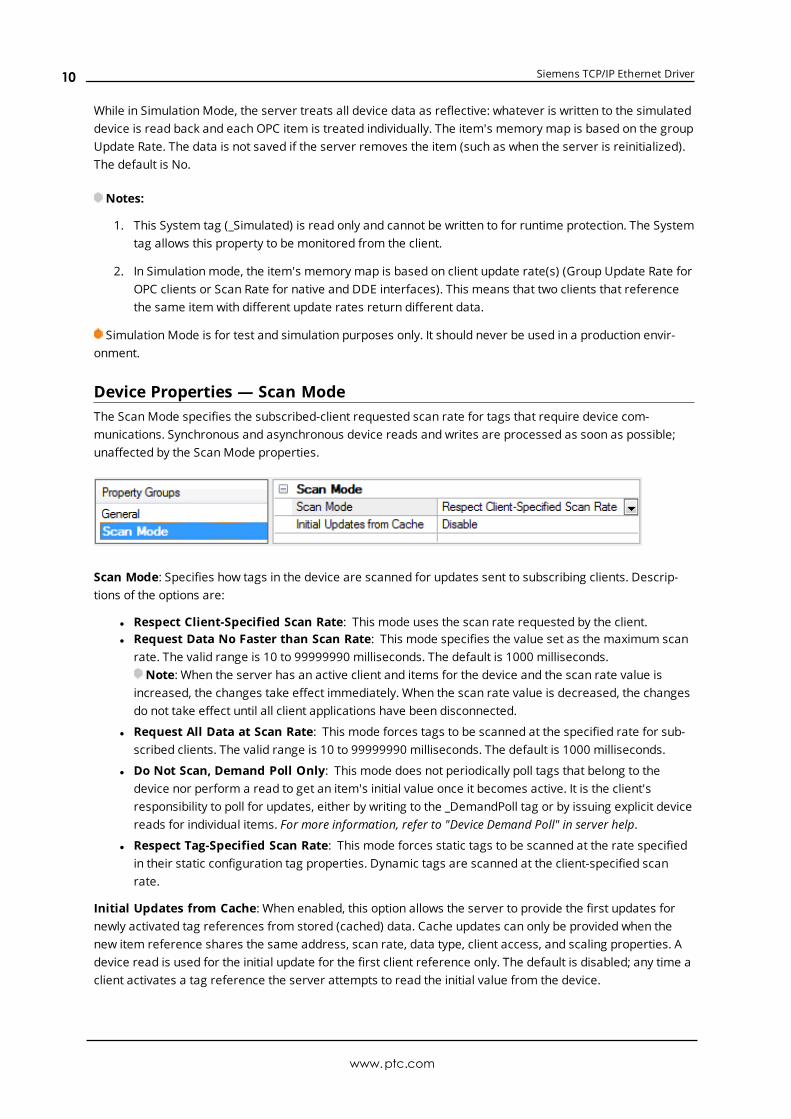
Scan Mode: Specifies how tags in the device are scanned for updates sent to subscribing clients. Descrip-tions of the options are:
l Respect Client-Specified Scan Rate: This mode uses the scan rate requested by the client.l Request Data No Faster than Scan Rate: This mode specifies the value set as the maximum scan
rate. The valid range is 10 to 99999990 milliseconds. The default is 1000 milliseconds.Note: When the server has an active client and items for the device and the scan rate value is
increased, the changes take effect immediately. When the scan rate value is decreased, the changesdo not take effect until all client applications have been disconnected.
l Request All Data at Scan Rate: This mode forces tags to be scanned at the specified rate for sub-scribed clients. The valid range is 10 to 99999990 milliseconds. The default is 1000 milliseconds.
l Do Not Scan, Demand Poll Only: This mode does not periodically poll tags that belong to thedevice nor perform a read to get an item's initial value once it becomes active. It is the client'sresponsibility to poll for updates, either by writing to the _DemandPoll tag or by issuing explicit devicereads for individual items. For more information, refer to "Device Demand Poll" in server help.
l Respect Tag-Specified Scan Rate: This mode forces static tags to be scanned at the rate specifiedin their static configuration tag properties. Dynamic tags are scanned at the client-specified scanrate.
Initial Updates from Cache: When enabled, this option allows the server to provide the first updates fornewly activated tag references from stored (cached) data. Cache updates can only be provided when thenew item reference shares the same address, scan rate, data type, client access, and scaling properties. Adevice read is used for the initial update for the first client reference only. The default is disabled; any time aclient activates a tag reference the server attempts to read the initial value from the device.
www.ptc.com
10
Siemens TCP/IP Ethernet Driver
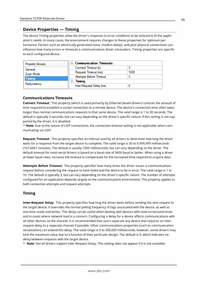
Device Properties — TimingThe device Timing properties allow the driver's response to error conditions to be tailored to fit the applic-ation's needs. In many cases, the environment requires changes to these properties for optimum per-formance. Factors such as electrically generated noise, modem delays, and poor physical connections caninfluence howmany errors or timeouts a communications driver encounters. Timing properties are specificto each configured device.
Communications TimeoutsConnect Timeout: This property (which is used primarily by Ethernet based drivers) controls the amount oftime required to establish a socket connection to a remote device. The device's connection time often takeslonger than normal communications requests to that same device. The valid range is 1 to 30 seconds. Thedefault is typically 3 seconds, but can vary depending on the driver's specific nature. If this setting is not sup-ported by the driver, it is disabled.Note: Due to the nature of UDP connections, the connection timeout setting is not applicable when com-
municating via UDP.
Request Timeout: This property specifies an interval used by all drivers to determine how long the driverwaits for a response from the target device to complete. The valid range is 50 to 9,999,999 milliseconds(167.6667 minutes). The default is usually 1000 milliseconds, but can vary depending on the driver. Thedefault timeout for most serial drivers is based on a baud rate of 9600 baud or better. When using a driverat lower baud rates, increase the timeout to compensate for the increased time required to acquire data.
Attempts Before Timeout: This property specifies howmany times the driver issues a communicationsrequest before considering the request to have failed and the device to be in error. The valid range is 1 to10. The default is typically 3, but can vary depending on the driver's specific nature. The number of attemptsconfigured for an application depends largely on the communications environment. This property applies toboth connection attempts and request attempts.
Timing
Inter-Request Delay: This property specifies how long the driver waits before sending the next request tothe target device. It overrides the normal polling frequency of tags associated with the device, as well asone-time reads and writes. This delay can be useful when dealing with devices with slow turnaround timesand in cases where network load is a concern. Configuring a delay for a device affects communications withall other devices on the channel. It is recommended that users separate any device that requires an inter-request delay to a separate channel if possible. Other communications properties (such as communicationserialization) can extend this delay. The valid range is 0 to 300,000 milliseconds; however, some drivers maylimit the maximum value due to a function of their particular design. The default is 0, which indicates nodelay between requests with the target device.
Note: Not all drivers support Inter-Request Delay. This setting does not appear if it is not available.
www.ptc.com
11

Siemens TCP/IP Ethernet Driver
Device Properties — Auto-DemotionThe Auto-Demotion properties can temporarily place a device off-scan in the event that a device is notresponding. By placing a non-responsive device offline for a specific time period, the driver can continue tooptimize its communications with other devices on the same channel. After the time period has beenreached, the driver re-attempts to communicate with the non-responsive device. If the device is responsive,the device is placed on-scan; otherwise, it restarts its off-scan time period.
Demote on Failure: When enabled, the device is automatically taken off-scan until it is responding again.Tip: Determine when a device is off-scan by monitoring its demoted state using the _AutoDemoted sys-
tem tag.
Timeouts to Demote: Specify howmany successive cycles of request timeouts and retries occur before thedevice is placed off-scan. The valid range is 1 to 30 successive failures. The default is 3.
Demotion Period: Indicate how long the device should be placed off-scan when the timeouts value isreached. During this period, no read requests are sent to the device and all data associated with the readrequests are set to bad quality. When this period expires, the driver places the device on-scan and allows foranother attempt at communications. The valid range is 100 to 3600000 milliseconds. The default is 10000milliseconds.
Discard Requests when Demoted: Select whether or not write requests should be attempted during theoff-scan period. Disable to always send write requests regardless of the demotion period. Enable to discardwrites; the server automatically fails any write request received from a client and does not post a messageto the Event Log.
Device Properties — Tag GenerationThe automatic tag database generation features make setting up an application a plug-and-play operation.Select communications drivers can be configured to automatically build a list of tags that correspond todevice-specific data. These automatically generated tags (which depend on the nature of the supportingdriver) can be browsed from the clients.
Not all devices and drivers support full automatic tag database generation and not all support the same datatypes. Consult the data types descriptions or the supported data type lists for each driver for specifics.
If the target device supports its own local tag database, the driver reads the device's tag information anduses the data to generate tags within the server. If the device does not natively support named tags, thedriver creates a list of tags based on driver-specific information. An example of these two conditions is as fol-lows:
1. If a data acquisition system supports its own local tag database, the communications driver uses thetag names found in the device to build the server's tags.
2. If an Ethernet I/O system supports detection of its own available I/Omodule types, the com-
www.ptc.com
12
Siemens TCP/IP Ethernet Driver
munications driver automatically generates tags in the server that are based on the types of I/Omod-ules plugged into the Ethernet I/O rack.
Note: Automatic tag database generation's mode of operation is completely configurable. For more inform-ation, refer to the property descriptions below.
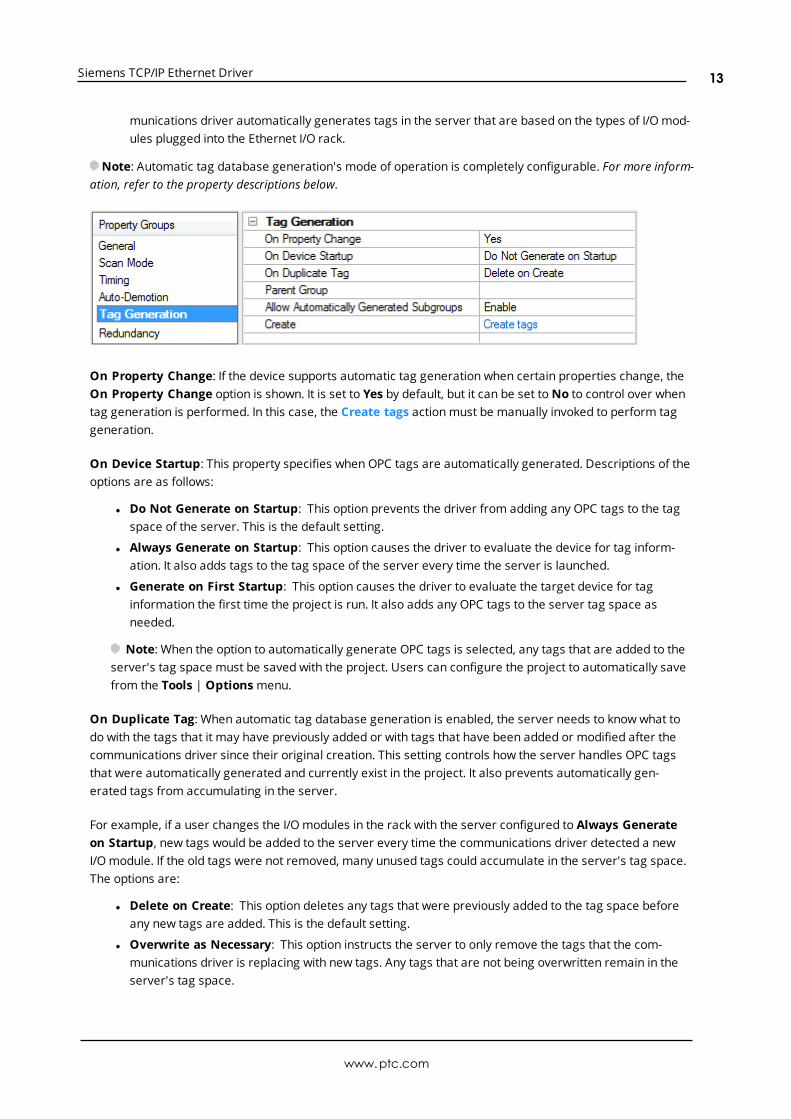
On Property Change: If the device supports automatic tag generation when certain properties change, theOn Property Change option is shown. It is set to Yes by default, but it can be set toNo to control over whentag generation is performed. In this case, the Create tags actionmust be manually invoked to perform taggeneration.
On Device Startup: This property specifies when OPC tags are automatically generated. Descriptions of theoptions are as follows:
l Do Not Generate on Startup: This option prevents the driver from adding any OPC tags to the tagspace of the server. This is the default setting.
l Always Generate on Startup: This option causes the driver to evaluate the device for tag inform-ation. It also adds tags to the tag space of the server every time the server is launched.
l Generate on First Startup: This option causes the driver to evaluate the target device for taginformation the first time the project is run. It also adds any OPC tags to the server tag space asneeded.
Note: When the option to automatically generate OPC tags is selected, any tags that are added to theserver's tag space must be saved with the project. Users can configure the project to automatically savefrom the Tools | Optionsmenu.
On Duplicate Tag: When automatic tag database generation is enabled, the server needs to know what todo with the tags that it may have previously added or with tags that have been added or modified after thecommunications driver since their original creation. This setting controls how the server handles OPC tagsthat were automatically generated and currently exist in the project. It also prevents automatically gen-erated tags from accumulating in the server.
For example, if a user changes the I/Omodules in the rack with the server configured to Always Generateon Startup, new tags would be added to the server every time the communications driver detected a newI/Omodule. If the old tags were not removed, many unused tags could accumulate in the server's tag space.The options are:
l Delete on Create: This option deletes any tags that were previously added to the tag space beforeany new tags are added. This is the default setting.
l Overwrite as Necessary: This option instructs the server to only remove the tags that the com-munications driver is replacing with new tags. Any tags that are not being overwritten remain in theserver's tag space.
www.ptc.com
13

Siemens TCP/IP Ethernet Driver
l Do not Overwrite: This option prevents the server from removing any tags that were previously gen-erated or already existed in the server. The communications driver can only add tags that are com-pletely new.
l Do not Overwrite, Log Error: This option has the same effect as the prior option, and also posts anerror message to the server's Event Log when a tag overwrite would have occurred.
Note: Removing OPC tags affects tags that have been automatically generated by the com-munications driver as well as any tags that have been added using names that match generated tags.Users should avoid adding tags to the server using names that may match tags that are automaticallygenerated by the driver.
Parent Group: This property keeps automatically generated tags frommixing with tags that have beenenteredmanually by specifying a group to be used for automatically generated tags. The name of the groupcan be up to 256 characters. This parent group provides a root branch to which all automatically generatedtags are added.
Allow Automatically Generated Subgroups: This property controls whether the server automatically cre-ates subgroups for the automatically generated tags. This is the default setting. If disabled, the server gen-erates the device's tags in a flat list without any grouping. In the server project, the resulting tags are namedwith the address value. For example, the tag names are not retained during the generation process.
Note: If, as the server is generating tags, a tag is assigned the same name as an existing tag, the systemautomatically increments to the next highest number so that the tag name is not duplicated. For example, ifthe generation process creates a tag named "AI22" that already exists, it creates the tag as "AI23" instead.
Create: Initiates the creation of automatically generated OPC tags. If the device's configuration has beenmodified, Create tags forces the driver to reevaluate the device for possible tag changes. Its ability to beaccessed from the System tags allows a client application to initiate tag database creation.
Note: Create tags is disabled if the Configuration edits a project offline.
Device Properties — Communications Parameters
Port Number: This parameter specifies the port number that the remote CP is configured to use. Thedefault setting for IE TCP/IP is 102 (TSAP). The default setting for NetLink is 1099.Note: It is recommended that the default port be used for most applications, where the server and the PLC
exist on the same network. For an application using the Internet through firewalls and advanced routers, theport number can be changed to allow these operations to occur. In most cases, however, the PLC onlyaccepts a connection on port 102/1099 andmay require router forwarding.
MPI ID: This parameter is for NetLink only, and is configured for the port in which the NetLink adapter is con-nected. It does not apply to models utilizing the IE TCP/IP CPs (such as S7-300 and S7-400). A maximum oftwo connections or devices via TCP are possible when using the NetLink adapter.
www.ptc.com
14
Siemens TCP/IP Ethernet Driver
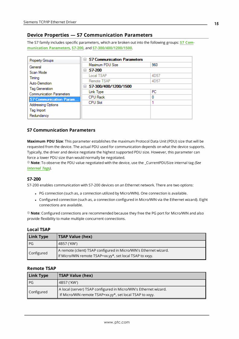
Device Properties — S7 Communication ParametersThe S7 family includes specific parameters, which are broken out into the following groups: S7 Com-munication Parameters, S7-200, and S7-300/400/1200/1500.
S7 Communication Parameters
Maximum PDU Size: This parameter establishes the maximum Protocol Data Unit (PDU) size that will berequested from the device. The actual PDU used for communication depends on what the device supports.Typically, the driver and device negotiate the highest supported PDU size. However, this parameter canforce a lower PDU size than would normally be negotiated.Note: To observe the PDU value negotiated with the device, use the _CurrentPDUSize internal tag (See
Internal Tags).
S7-200S7-200 enables communication with S7-200 devices on an Ethernet network. There are two options:
l PG connection (such as, a connection utilized by Micro/WIN). One connection is available.
l Configured connection (such as, a connection configured in Micro/WIN via the Ethernet wizard). Eightconnections are available.
Note: Configured connections are recommended because they free the PG port for Micro/WIN and alsoprovide flexibility to make multiple concurrent connections.
Local TSAPLink Type TSAP Value (hex)
PG 4B57 ('KW')
ConfiguredA remote (client) TSAP configured in Micro/WIN's Ethernet wizard.If Micro/WIN remote TSAP=xx.yy*, set local TSAP to xxyy.
Remote TSAPLink Type TSAP Value (hex)
PG 4B57 ('KW')
ConfiguredA local (server) TSAP configured in Micro/WIN's Ethernet wizard.If Micro/WIN remote TSAP=xx.yy*, set local TSAP to xxyy.
www.ptc.com
15
Siemens TCP/IP Ethernet Driver
*TSAP as displayed in Micro/WIN's Ethernet wizard. When accessed from Vmemory, the value may be indecimal form. For example, if TSAP is 10.00, the V memory value is 1000 hex or 4096 decimal. The valuesentered for Local TSAP must be in hexadecimal notation; in this example, the value 1000 would be entered.
Tip: Local TSAP==Micro/WIN remote TSAP, Remote TSAP==Micro/WIN local TSAP.
For information on using the CP243-1 module, refer to How to Configure S7-200 Connections inMicro/WIN.
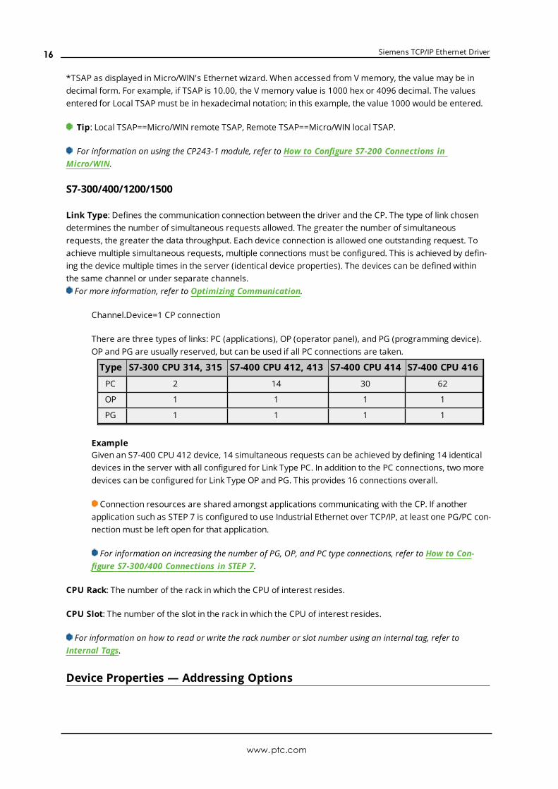
S7-300/400/1200/1500
Link Type: Defines the communication connection between the driver and the CP. The type of link chosendetermines the number of simultaneous requests allowed. The greater the number of simultaneousrequests, the greater the data throughput. Each device connection is allowed one outstanding request. Toachieve multiple simultaneous requests, multiple connections must be configured. This is achieved by defin-ing the device multiple times in the server (identical device properties). The devices can be defined withinthe same channel or under separate channels.For more information, refer to Optimizing Communication.
Channel.Device=1 CP connection
There are three types of links: PC (applications), OP (operator panel), and PG (programming device).OP and PG are usually reserved, but can be used if all PC connections are taken.
Type S7-300 CPU 314, 315 S7-400 CPU 412, 413 S7-400 CPU 414 S7-400 CPU 416
PC 2 14 30 62
OP 1 1 1 1
PG 1 1 1 1
ExampleGiven an S7-400 CPU 412 device, 14 simultaneous requests can be achieved by defining 14 identicaldevices in the server with all configured for Link Type PC. In addition to the PC connections, two moredevices can be configured for Link Type OP and PG. This provides 16 connections overall.
Connection resources are shared amongst applications communicating with the CP. If anotherapplication such as STEP 7 is configured to use Industrial Ethernet over TCP/IP, at least one PG/PC con-nectionmust be left open for that application.
For information on increasing the number of PG, OP, and PC type connections, refer to How to Con-figure S7-300/400 Connections in STEP 7.
CPU Rack: The number of the rack in which the CPU of interest resides.
CPU Slot: The number of the slot in the rack in which the CPU of interest resides.
For information on how to read or write the rack number or slot number using an internal tag, refer toInternal Tags.
Device Properties — Addressing Options
www.ptc.com
16
Siemens TCP/IP Ethernet Driver
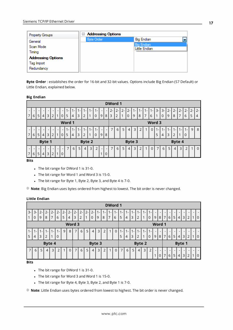
Byte Order : establishes the order for 16-bit and 32-bit values. Options include Big Endian (S7 Default) orLittle Endian, explained below.
Big Endian
DWord 1
-7
-6
-5
-4
-3
-2
-1
-0
1-5
1-4
1-3
1-2
1-1
1-0
-9
-8
2-3
2-2
2-1
2-0
1-9
1-8
1-7
1-6
3-1
3-0
2-9
2-8
2-7
2-6
2-5
2-4
Word 1 Word 3
-7
-6
-5
-4
-3
-2
-1
-0
1-5
1-4
1-3
1-2
1-1
1-0
-9
-8
7 6 5 4 3 2 1 0 1-5
1-4
1-3
1-2
1-1
1-0
9 8
Byte 1 Byte 2 Byte 3 Byte 4
-7
-6
-5
-4
-3
-2
-1
-0
7 6 5 4 3 2 -1
-0
7 6 5 4 3 2 1 0 7 6 5 4 3 2 1 0
Bits
l The bit range for DWord 1 is 31-0.
l The bit range for Word 1 andWord 3 is 15-0.
l The bit range for Byte 1, Byte 2, Byte 3, and Byte 4 is 7-0.
Note: Big Endian uses bytes ordered from highest to lowest. The bit order is never changed.
Little Endian
DWord 1
3-1
3-0
2-9
2-8
2-7
2-6
2-5
2-4
2-3
2-2
2-1
2-0
1-9
1-8
1-7
1-6
1-5
1-4
1-3
1-2
1-1
1-0
-9
-8
-7
-6
-5
-4
-3
-2
-1
-0
Word 3 Word 1
1-5
1-4
1-3
1-2
1-1
1-0
9 8 7 6 5 4 3 2 1 0 1-5
1-4
1-3
1-2
1-1
1-0
-9
-8
-7
-6
-5
-4
-3
-2
-1
-0
Byte 4 Byte 3 Byte 2 Byte 1
7 6 5 4 3 2 1 0 7 6 5 4 3 2 1 0 7 6 5 4 3 2 -1
-0
-7
-6
-5
-4
-3
-2
-1
-0
Bits
l The bit range for DWord 1 is 31-0.
l The bit range for Word 3 andWord 1 is 15-0.
l The bit range for Byte 4, Byte 3, Byte 2, and Byte 1 is 7-0.
Note: Little Endian uses bytes ordered from lowest to highest. The bit order is never changed.
www.ptc.com
17

Siemens TCP/IP Ethernet Driver
Device Properties — Tag ImportThe Tag Import parameters allow automatic tag database generation from projects defined in SiemensSTEP 7 or in Siemens TIA Portal that were exported via the TIA Portal Exporter.
Supported Models via Siemens STEP 7S7-300S7-400
Supported Models via Siemens TIA PortalS7-300S7-400S7-1200S7-1500
STEP 7 Tag Import
Tag Import Type: Select "Step 7 Project File" from the drop-downmenu.
STEP 7 Project (*.S7P): Locate and select the desired STEP 7 project file (*.S7P) from which to import tags.Note: The desired STEP 7 project file (*.S7P) must be located in the Step 7 project directory to import
tags.
Program Path: Specify the PLC program within the project for which tags should be generated. The pro-gram path format is "Station Name\CPU Name\Program Name" and the program path selection drop-downlist can be populated with stations that have single or multiple CPUs. When a station with multiple CPUs isfound, each CPU associated with the station has a CPU ID designator formatted as " @ ID x" appended to theCPU name portion of program path.For example: A SIMATIC 400 controller with two 400 CPUs would have two entries:
l "=K51 S7-400\K34 CPU @ ID 3\K34"
l "=K51 S7-400\CPU 416-3 DP @ ID 2\K51"
Note: Tag import for the Siemens S7-300 and S7-400 devices have been qualified for use with projects cre-ated from Siemens Simatic STEP 7 versions 5.3, 5.4, and 5.5.
Important: Tag import for the Siemens TCP/IP Ethernet Driver supports tag names and comments in thenative character set as specified by the Windows code page in the Siemens STEP 7 project's language file. Amissing, altered, corrupt, or incorrect Siemens STEP 7 language file may cause tag names and comments toimport incorrectly. Utilizing the STEP 7 language-neutral option (which allows text to be entered in a differentcharacter set than what is used in the STEP 7 language file) may also cause tag names and comments toimport incorrectly. The STEP 7 language file can be located in the Global sub-directory of the STEP 7 projectroot. Automatic tag generationmay result in the display of incorrect characters if the necessary languagepacks are not installed on the system.
See Also: Appendix: Configuring Siemens Connections
www.ptc.com
18
Siemens TCP/IP Ethernet Driver
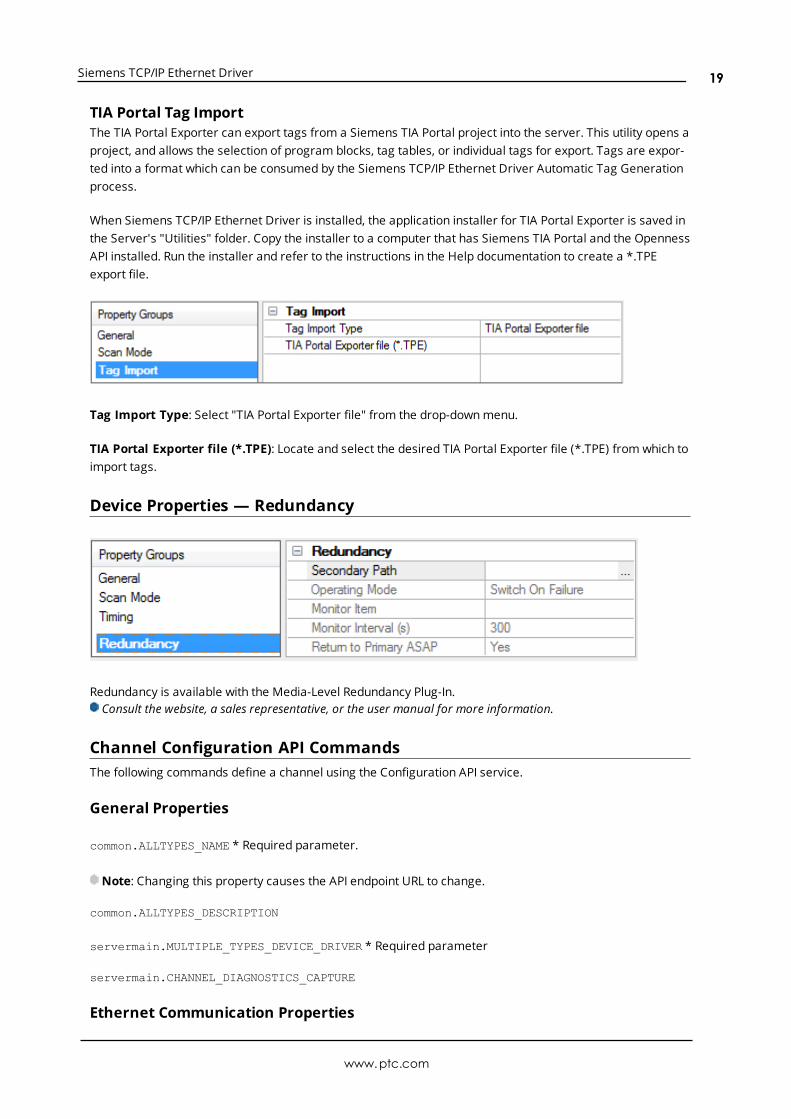
TIA Portal Tag ImportThe TIA Portal Exporter can export tags from a Siemens TIA Portal project into the server. This utility opens aproject, and allows the selection of program blocks, tag tables, or individual tags for export. Tags are expor-ted into a format which can be consumed by the Siemens TCP/IP Ethernet Driver Automatic Tag Generationprocess.
When Siemens TCP/IP Ethernet Driver is installed, the application installer for TIA Portal Exporter is saved inthe Server's "Utilities" folder. Copy the installer to a computer that has Siemens TIA Portal and the OpennessAPI installed. Run the installer and refer to the instructions in the Help documentation to create a *.TPEexport file.
Tag Import Type: Select "TIA Portal Exporter file" from the drop-downmenu.
TIA Portal Exporter file (*.TPE): Locate and select the desired TIA Portal Exporter file (*.TPE) from which toimport tags.
Device Properties — Redundancy
Redundancy is available with the Media-Level Redundancy Plug-In.Consult the website, a sales representative, or the user manual for more information.
Channel Configuration API CommandsThe following commands define a channel using the Configuration API service.
General Properties
common.ALLTYPES_NAME * Required parameter.
Note: Changing this property causes the API endpoint URL to change.
common.ALLTYPES_DESCRIPTION
servermain.MULTIPLE_TYPES_DEVICE_DRIVER * Required parameter
servermain.CHANNEL_DIAGNOSTICS_CAPTURE
Ethernet Communication Properties
www.ptc.com
19
Siemens TCP/IP Ethernet Driver
servermain.CHANNEL_ETHERNET_COMMUNICATIONS_NETWORK_ADAPTER_STRING
Advanced Properties
servermain.CHANNEL_NON_NORMALIZED_FLOATING_POINT_HANDLING * Required parameter
Write Optimizations
servermain.CHANNEL_WRITE_OPTIMIZATIONS_METHOD
servermain.CHANNEL_WRITE_OPTIMIZATIONS_DUTY_CYCLE
See Also: The server help system Configuration API Service section.
Siemens TCP/IP Ethernet Channel Setup with API CommandsThe minimum required properties to create a Siemens TCP/IP Ethernet device under a channel are com-mon.ALLTYPES_NAME, and servermain.MULTIPLE_TYPES_DEVICE_DRIVER. All other properties will be set totheir default values.
JSON Example
Below is an example JSON blob that can be used in a POST to the channel endpoint to make a channelnamed Channel1.
{ “common.ALLTYPES_NAME”: ”Channel1”, “servermain.MULTIPLE_TYPES_DEVICE_DRIVER”: “Siemens TCP/IP Ethernet"}
If there is a channel named Channel1 and a device name Device1 with the server running on the local host,the GET request query would be sent to:
/config/v1/project/channels/Channel1/devices/Device1?content=property_definitions
/config/v1/doc/drivers/Siemens%20TCP~IP%20Ethernet/Devices has the enumerated details for devices.
Device Configuration API CommandsThe following commands define a channel using the Configuration API service.
General Properties
common.ALLTYPES_NAME
common.ALLTYPES_DESCRIPTION
servermain.DEVICE_CHANNEL_ASSIGNMENT
servermain.MULTIPLE_TYPES_DEVICE_DRIVER
servermain.DEVICE_MODEL
servermain.DEVICE_ID_STRING
www.ptc.com
20
Siemens TCP/IP Ethernet Driver
servermain.DEVICE_DATA_COLLECTION
servermain.DEVICE_SIMULATED
Scan Mode
servermain.DEVICE_SCAN_MODE * Required parameter
servermain.DEVICE_SCAN_MODE_RATE_MS
servermain.DEVICE_SCAN_MODE_RATE_MS
servermain.DEVICE_SCAN_MODE_PROVIDE_INITIAL_UPDATES_FROM_CACHE
Auto Demotion
servermain.DEVICE_AUTO_DEMOTION_ENABLE_ON_COMMUNICATIONS_FAILURES
servermain.DEVICE_AUTO_DEMOTION_DEMOTE_AFTER_SUCCESSIVE_TIMEOUTS
servermain.DEVICE_AUTO_DEMOTION_PERIOD_MS
servermain.DEVICE_AUTO_DEMOTION_DISCARD_WRITES
Tag Generation
servermain.DEVICE_TAG_GENERATION_ON_STARTUP * Required parameter
servermain.DEVICE_TAG_GENERATION_DUPLICATE_HANDLING * Required parameter
servermain.DEVICE_TAG_GENERATION_GROUP
servermain.DEVICE_TAG_GENERATION_ALLOW_SUB_GROUPS
Tip: To Invoke Automatic Tag Generation, send a PUT with an empty body to the TagGeneration serviceendpoint on the device.See Also: For more information see Services help.
Timingservermain.DEVICE_CONNECTION_TIMEOUT_SECONDS
servermain.DEVICE_REQUEST_TIMEOUT_MILLISECONDS
servermain.DEVICE_RETRY_ATTEMPTS
servermain.DEVICE_INTER_REQUEST_DELAY_MILLISECONDS
See Also: The server help system Configuration API Service section.
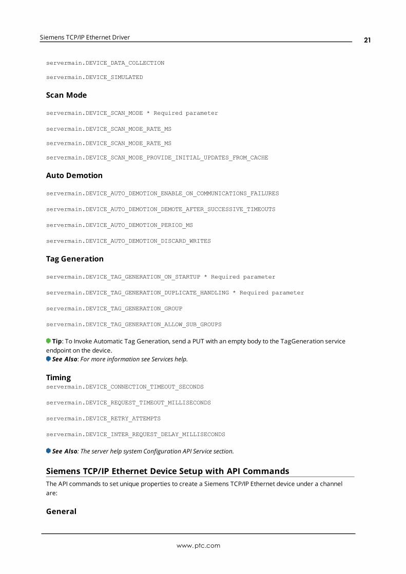
Siemens TCP/IP Ethernet Device Setup with API CommandsThe API commands to set unique properties to create a Siemens TCP/IP Ethernet device under a channelare:
General
www.ptc.com
21
Siemens TCP/IP Ethernet Driver
common.ALLTYPES_NAME
common.ALLTYPES_DESCRIPTION
servermain.DEVICE_CHANNEL_ASSIGNMENT
servermain.MULTIPLE_TYPES_DEVICE_DRIVER
servermain.DEVICE_MODEL
servermain.DEVICE_ID_STRING
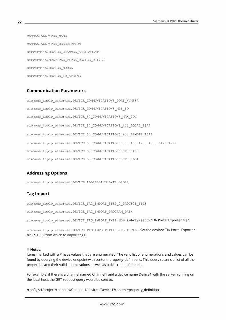
Communication Parameters
siemens_tcpip_ethernet.DEVICE_COMMUNICATIONS_PORT_NUMBER
siemens_tcpip_ethernet.DEVICE_COMMUNICATIONS_MPI_ID
siemens_tcpip_ethernet.DEVICE_S7_COMMUNICATIONS_MAX_PDU
siemens_tcpip_ethernet.DEVICE_S7_COMMUNICATIONS_200_LOCAL_TSAP
siemens_tcpip_ethernet.DEVICE_S7_COMMUNICATIONS_200_REMOTE_TSAP
siemens_tcpip_ethernet.DEVICE_S7_COMMUNICATIONS_300_400_1200_1500_LINK_TYPE
siemens_tcpip_ethernet.DEVICE_S7_COMMUNICATIONS_CPU_RACK
siemens_tcpip_ethernet.DEVICE_S7_COMMUNICATIONS_CPU_SLOT
Addressing Options
siemens_tcpip_ethernet.DEVICE_ADDRESSING_BYTE_ORDER
Tag Import
siemens_tcpip_ethernet.DEVICE_TAG_IMPORT_STEP_7_PROJECT_FILE
siemens_tcpip_ethernet.DEVICE_TAG_IMPORT_PROGRAM_PATH
siemens_tcpip_ethernet.DEVICE_TAG_IMPORT_TYPE: This is always set to "TIA Portal Exporter file".
siemens_tcpip_ethernet.DEVICE_TAG_IMPORT_TIA_EXPORT_FILE: Set the desired TIA Portal Exporterfile (*.TPE) from which to import tags.
Notes:Items marked with a * have values that are enumerated. The valid list of enumerations and values can befound by querying the device endpoint with content=property_definitions. This query returns a list of all theproperties and their valid enumerations as well as a description for each.
For example, if there is a channel named Channel1 and a device name Device1 with the server running onthe local host, the GET request query would be sent to:
/config/v1/project/channels/Channel1/devices/Device1?content=property_definitions
www.ptc.com
22
Siemens TCP/IP Ethernet Driver
/config/v1/doc/drivers/Siemens%20TCP~IP%20Ethernet/Devices has the enumerated details for devices.
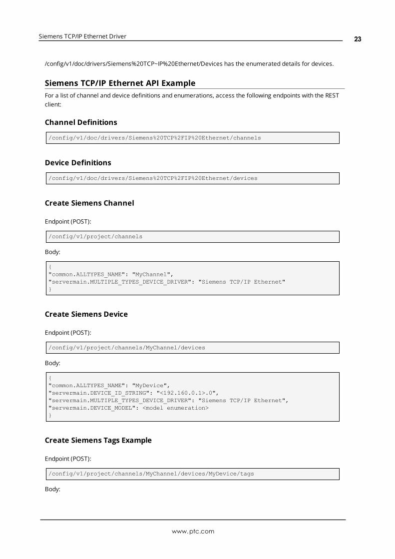
Siemens TCP/IP Ethernet API ExampleFor a list of channel and device definitions and enumerations, access the following endpoints with the RESTclient:
Channel Definitions
/config/v1/doc/drivers/Siemens%20TCP%2FIP%20Ethernet/channels
Device Definitions
/config/v1/doc/drivers/Siemens%20TCP%2FIP%20Ethernet/devices
Create Siemens Channel
Endpoint (POST):
/config/v1/project/channels
Body:
{"common.ALLTYPES_NAME": "MyChannel","servermain.MULTIPLE_TYPES_DEVICE_DRIVER": "Siemens TCP/IP Ethernet"}
Create Siemens Device
Endpoint (POST):
/config/v1/project/channels/MyChannel/devices
Body:
{"common.ALLTYPES_NAME": "MyDevice","servermain.DEVICE_ID_STRING": "<192.160.0.1>.0","servermain.MULTIPLE_TYPES_DEVICE_DRIVER": "Siemens TCP/IP Ethernet","servermain.DEVICE_MODEL": <model enumeration>}
Create Siemens Tags Example
Endpoint (POST):
/config/v1/project/channels/MyChannel/devices/MyDevice/tags
Body:
www.ptc.com
23

Siemens TCP/IP Ethernet Driver
[{"common.ALLTYPES_NAME": "MyTag1","servermain.TAG_ADDRESS": "DB1,INT00"}{"common.ALLTYPES_NAME": "MyTag2","servermain.TAG_ADDRESS": "DB1,INT01"}]
See server help for more information on configuring projects over the Configuration API.
Optimizing CommunicationsThe Siemens TCP/IP Ethernet Driver was designed to provide the best performance with the least amount ofimpact on the system's overall performance. While the Siemens TCP/IP Ethernet Driver is fast, there are acouple of guidelines that can be used to optimize the application and gain maximum performance.
This server refers to communications protocols like Siemens TCP/IP Ethernet as a channel. Each channeldefined in the application represents a separate path of execution in the server. Once a channel has beendefined, a series of devices can then be defined under that channel. Each of these devices represents asingle Siemens TCP/IP Ethernet controller from which data will be collected. Although this approach to defin-ing the application provides a high level of performance, it does not take full advantage of the SiemensTCP/IP Ethernet Driver or the network. An example of how the applicationmay appear when configuredusing a single channel is shown below.
Each device appears under a single Siemens TCP/IP Ethernet channel. In this con-figuration, the driver must move from one device to the next as quickly as possible togather information at an effective rate. As more devices are added or more inform-ation is requested from a single device, the overall update rate begins to suffer.
If the Siemens TCP/IP Ethernet Driver could only define one channel, then the example above would be theonly option available; however, the driver can define up to 256 channels. Using multiple channels distributesthe data collection workload by simultaneously issuing multiple requests to the network. An example of howthe same applicationmay appear when configured using multiple channels is shown below.
Each device has now been defined under its own channel. In this new configuration, asingle path of execution is dedicated to the task of gathering data from each device.
The performance will improve even if the application has more than 256 devices.While 256 or fewer devices may be ideal, the application will still benefit from addi-tional channels. Although spreading the device load across all channels will cause theserver to move from device to device again, it can now do so with far less devices toprocess on a single channel.
Although the server limits the number of channels to 256, the device ultimately determines the number ofallowed connections. This constraint comes from the fact that some devices cannot support 256 con-nections. For these devices, the maximum number of channels defined should equal the maximum numberof connections allowed. For devices that support more than 256 connections, the maximum 256 channelsshould be defined, with devices spread evenly over these 256 channels.
www.ptc.com
24
Siemens TCP/IP Ethernet Driver
For more information on device connections, refer to Device Properties.
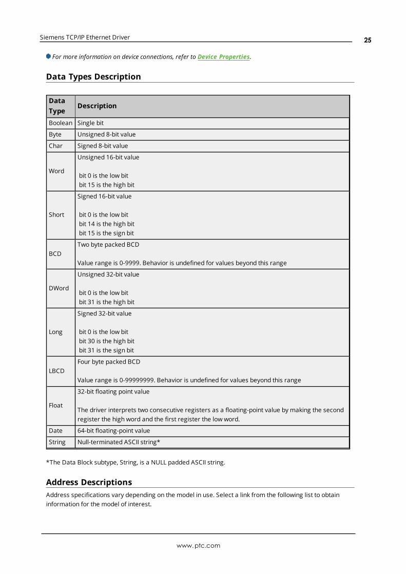
Data Types Description
DataType
Description
Boolean Single bit
Byte Unsigned 8-bit value
Char Signed 8-bit value
Word
Unsigned 16-bit value
bit 0 is the low bitbit 15 is the high bit
Short
Signed 16-bit value
bit 0 is the low bitbit 14 is the high bitbit 15 is the sign bit
BCDTwo byte packed BCD
Value range is 0-9999. Behavior is undefined for values beyond this range
DWord
Unsigned 32-bit value
bit 0 is the low bitbit 31 is the high bit
Long
Signed 32-bit value
bit 0 is the low bitbit 30 is the high bitbit 31 is the sign bit
LBCDFour byte packed BCD
Value range is 0-99999999. Behavior is undefined for values beyond this range
Float
32-bit floating point value
The driver interprets two consecutive registers as a floating-point value by making the secondregister the high word and the first register the low word.
Date 64-bit floating-point value
String Null-terminated ASCII string*
*The Data Block subtype, String, is a NULL padded ASCII string.
Address DescriptionsAddress specifications vary depending on the model in use. Select a link from the following list to obtaininformation for the model of interest.
www.ptc.com
25
Siemens TCP/IP Ethernet Driver
S7-200 Address DescriptionsS7-300 Address DescriptionsS7-400 Address DescriptionsS7-1200 Address DescriptionsS7-1500 Address DescriptionsNetLink: S7-300 Address DescriptionsNetLink: S7-400 Address DescriptionsInternal Tags
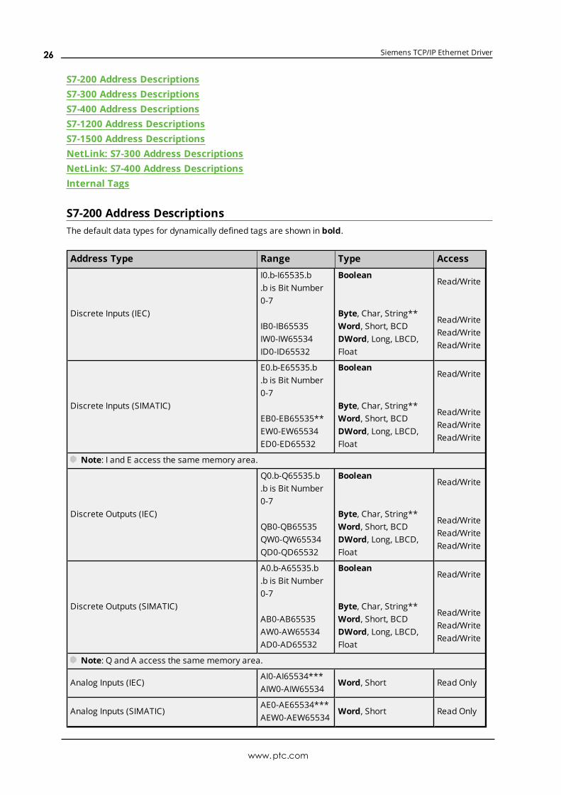
S7-200 Address DescriptionsThe default data types for dynamically defined tags are shown in bold.
Address Type Range Type Access
Discrete Inputs (IEC)
I0.b-I65535.b.b is Bit Number0-7
IB0-IB65535IW0-IW65534ID0-ID65532
Boolean
Byte, Char, String**Word, Short, BCDDWord, Long, LBCD,Float
Read/Write
Read/WriteRead/WriteRead/Write
Discrete Inputs (SIMATIC)
E0.b-E65535.b.b is Bit Number0-7
EB0-EB65535**EW0-EW65534ED0-ED65532
Boolean
Byte, Char, String**Word, Short, BCDDWord, Long, LBCD,Float
Read/Write
Read/WriteRead/WriteRead/Write
Note: I and E access the same memory area.
Discrete Outputs (IEC)
Q0.b-Q65535.b.b is Bit Number0-7
QB0-QB65535QW0-QW65534QD0-QD65532
Boolean
Byte, Char, String**Word, Short, BCDDWord, Long, LBCD,Float
Read/Write
Read/WriteRead/WriteRead/Write
Discrete Outputs (SIMATIC)
A0.b-A65535.b.b is Bit Number0-7
AB0-AB65535AW0-AW65534AD0-AD65532
Boolean
Byte, Char, String**Word, Short, BCDDWord, Long, LBCD,Float
Read/Write
Read/WriteRead/WriteRead/Write
Note: Q and A access the same memory area.
Analog Inputs (IEC)AI0-AI65534***AIW0-AIW65534
Word, Short Read Only
Analog Inputs (SIMATIC)AE0-AE65534***AEW0-AEW65534
Word, Short Read Only
www.ptc.com
26
Siemens TCP/IP Ethernet Driver
Address Type Range Type Access
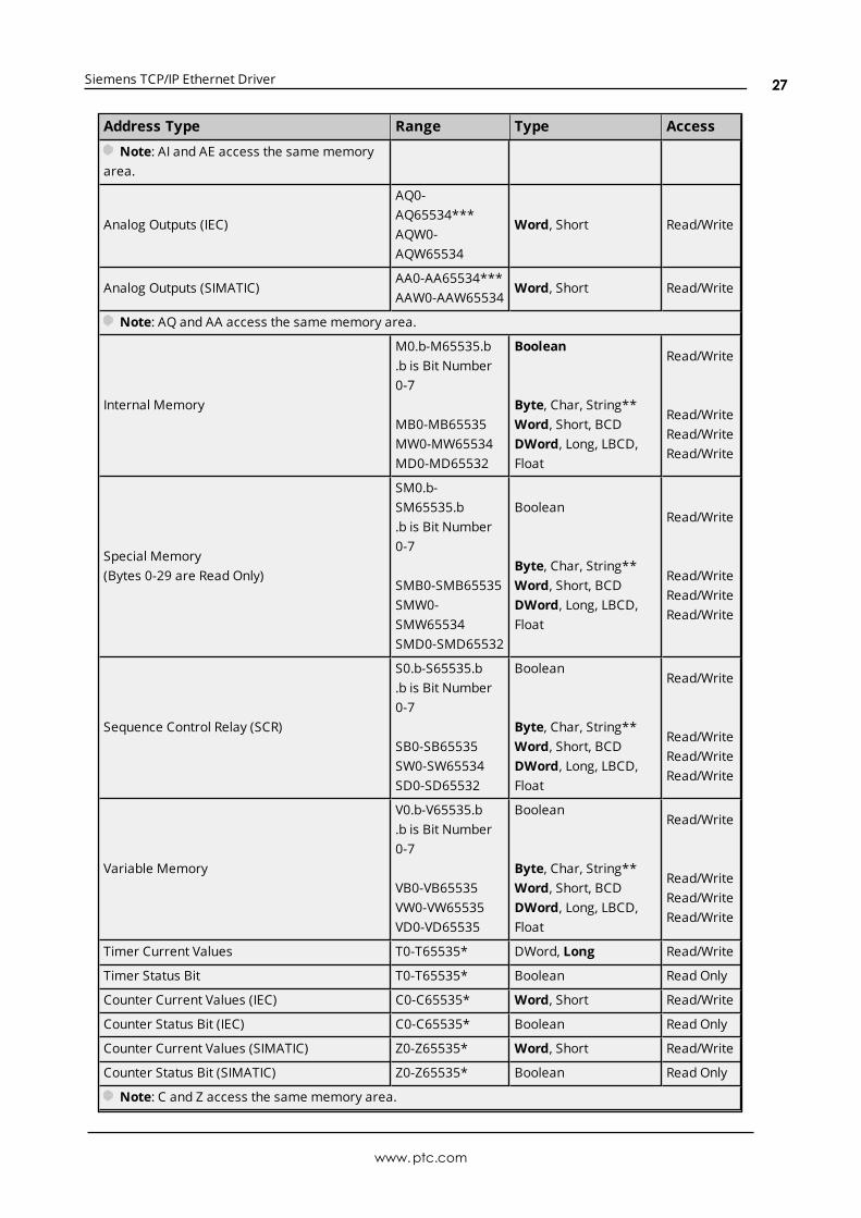
Note: AI and AE access the same memoryarea.
Analog Outputs (IEC)
AQ0-AQ65534***AQW0-AQW65534
Word, Short Read/Write
Analog Outputs (SIMATIC)AA0-AA65534***AAW0-AAW65534
Word, Short Read/Write
Note: AQ and AA access the same memory area.
Internal Memory
M0.b-M65535.b.b is Bit Number0-7
MB0-MB65535MW0-MW65534MD0-MD65532
Boolean
Byte, Char, String**Word, Short, BCDDWord, Long, LBCD,Float
Read/Write
Read/WriteRead/WriteRead/Write
Special Memory(Bytes 0-29 are Read Only)
SM0.b-SM65535.b.b is Bit Number0-7
SMB0-SMB65535SMW0-SMW65534SMD0-SMD65532
Boolean
Byte, Char, String**Word, Short, BCDDWord, Long, LBCD,Float
Read/Write
Read/WriteRead/WriteRead/Write
Sequence Control Relay (SCR)
S0.b-S65535.b.b is Bit Number0-7
SB0-SB65535SW0-SW65534SD0-SD65532
Boolean
Byte, Char, String**Word, Short, BCDDWord, Long, LBCD,Float
Read/Write
Read/WriteRead/WriteRead/Write
Variable Memory
V0.b-V65535.b.b is Bit Number0-7
VB0-VB65535VW0-VW65535VD0-VD65535
Boolean
Byte, Char, String**Word, Short, BCDDWord, Long, LBCD,Float
Read/Write
Read/WriteRead/WriteRead/Write
Timer Current Values T0-T65535* DWord, Long Read/Write
Timer Status Bit T0-T65535* Boolean Read Only
Counter Current Values (IEC) C0-C65535* Word, Short Read/Write
Counter Status Bit (IEC) C0-C65535* Boolean Read Only
Counter Current Values (SIMATIC) Z0-Z65535* Word, Short Read/Write
Counter Status Bit (SIMATIC) Z0-Z65535* Boolean Read Only
Note: C and Z access the same memory area.
www.ptc.com
27

Siemens TCP/IP Ethernet Driver
Address Type Range Type Access
High-Speed Counter HC0-HC65535* DWord, Long Read Only
*These memory types/subtypes do not support arrays.**Byte memory types (MB) support strings. The syntax for strings is <address>.<length> where 0 < length <=932 (see notes below).***For Analog Inputs and Outputs, the address must be even (AI0, AI2, AI4, and so forth).
Notes:
1. All offsets for memory types I, Q, M, S, and SM represent a byte starting location within the specifiedmemory type.
2. Use caution whenmodifying Word, Short, DWord, and Long types. For I, Q, and F, each address startsat a byte offset within the device. Therefore, Words MW0 andMW1 overlap at byte 1. Writing to MW0will also modify the value held in MW1. Similarly, DWord, and Long types can also overlap. It is recom-mended that these memory types be used so that overlapping does not occur. For example, DWordMD0, MD4, MD8, and so on can be used to prevent overlapping bytes.
3. The total number of bytes being requested cannot exceed the data portion of the negotiated PDUsize. For example, for a 960-byte PDU size, the largest single array that may be read or written is 932bytes. If arrays exceed the negotiated PDU size, they may fail to be read or written.
ArraysAll memory types/subtypes with the exception of those marked with an asterisk support arrays. The valid syn-tax for declaring an array is as follows:
<address>[rows][cols]<address>.rows.cols<address>,rows,cols<address>_rows_cols
Notes:
1. If no rows are specified, a row count of 1 is assumed.
2. For Word, Short, and BCD arrays, the base address + (rows * cols * 2) cannot exceed 65536. Keep inmind that the elements of the array are words, located on a word boundary. For example, IW0[4]would return IW0, IW2, IW4, and IW6.
3. For Float, DWord, Long, and Long BCD arrays, the base address + (rows * cols * 4) cannot exceed65536. Keep in mind that the elements of the array are DWord, located on a DWord boundary. Forexample, ID0[4] will return ID0, ID4, ID8, and ID12.
4. For all arrays, the total number of bytes requested cannot exceed the data portion of the negotiatedPDU size. For example, for a 960-byte PDU size, the largest single array that may be read or writtenis 932 bytes. If arrays exceed the negotiated PDU size, they may fail to be read or written.
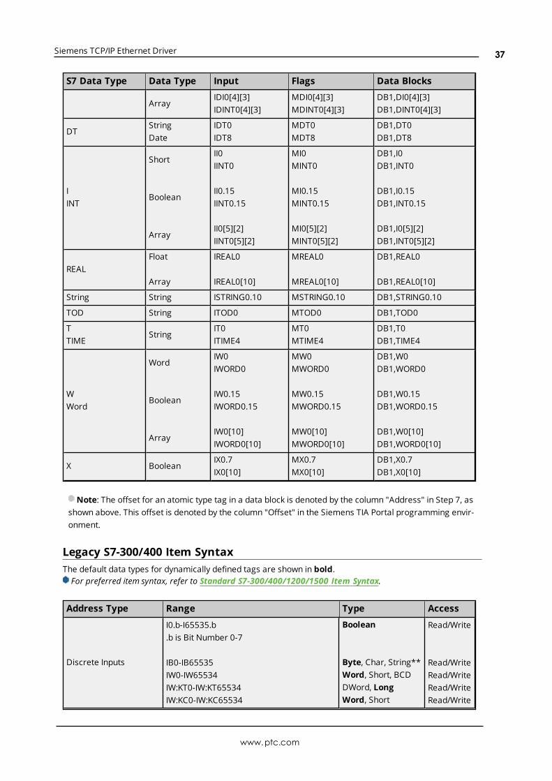
Note: The offset for an atomic type tag in a data block is denoted by the column "Address" in Step 7, asshown above. This offset is denoted by the column "Offset" in the Siemens TIA Portal programming envir-onment.
S7-300 Address DescriptionsStandard Support
www.ptc.com
28
Siemens TCP/IP Ethernet Driver
S7-300/400/1200/1500 Item SyntaxInternal Tags
Third-Party SupportFor users familiar with third-party applications, limited addressing support is available.
Legacy SupportLegacy S7-300/400 Item Syntax
All brand and product names are trademarks, registered trademarks, or service marks of their respective hold-ers.
S7-400 Address DescriptionsStandard SupportS7-300/400/1200/1500 Item SyntaxInternal Tags
Third-Party SupportFor users familiar with third-party applications, limited addressing support is available.
Legacy SupportLegacy S7-300/400 Item Syntax
All brand and product names are trademarks, registered trademarks, or service marks of their respective hold-ers.
S7-1200 Address DescriptionsStandard SupportS7-300/400/1200/1500 Item SyntaxInternal Tags
Third-Party SupportFor users familiar with third-party applications, limited addressing support is available.
Legacy SupportLegacy S7-300/400 Item Syntax
All brand and product names are trademarks, registered trademarks, or service marks of their respective hold-ers.
S7-1500 Address DescriptionsStandard SupportS7-300/400/1200/1500 Item SyntaxInternal Tags
Third-Party SupportFor users familiar with third-party applications, limited addressing support is available.
Legacy Support
www.ptc.com
29

Siemens TCP/IP Ethernet Driver
Legacy S7-300/400 Item Syntax
All brand and product names are trademarks, registered trademarks, or service marks of their respective hold-ers.
NetLink: S7-300 Address DescriptionsStandard SupportS7-300/400/1200/1500 Item Syntax
Third-Party SupportFor users familiar with third-party applications, limited addressing support is available.
Legacy SupportLegacy S7-300/400 Item Syntax
All brand and product names are trademarks, registered trademarks, or service marks of their respective holders
NetLink: S7-400 Address DescriptionsStandard SupportS7-300/400/1200/1500 Item Syntax
Third-Party SupportFor users familiar with third-party applications, limited addressing support is available.
Legacy SupportLegacy S7-300/400 Item Syntax
All brand and product names are trademarks, registered trademarks, or service marks of their respective holders
Internal TagsAlthough the following internal tags are not visible in the server configuration, they can be browsed by theOPC client. They can be found under the <Channel Name>.<Device Name>._InternalTags group. If the OPC cli-ent does not support browsing, or if a non-OPC client is being used, the tags can be created dynamically andstatically by using the addresses given below.
Note: The tags listed in the following table are valid for the S7-300, S7-400, S7-1200, and S7-1500 devicemodels. The default data types are shown in bold.
DeviceAddress
Description RangeDataType
Access
_RACKNumber of the rack in which the CPU of interest resides.On changing this device property, the connection with theCPU is re-established.
0-7Byte,Short
Read/Write
_SLOT Number of the slot in which the CPU of interest resides.On changing this device property, the connection with theCPU is re-established.
2-31 Byte,Short
Read/Write
_Cur-rentPDUSize
Subsequent to connection, this tag shows the size of theProtocol Data Unit which has been negotiated with the
240,480,
Word Read
www.ptc.com
30

Siemens TCP/IP Ethernet Driver
DeviceAddress
Description RangeDataType
Access
device. Prior to connection it shows the maximum con-figured PDU value.
960
Standard S7-300/400/1200/1500 Item SyntaxAddress SyntaxInput, Output, Peripheral, Flag Memory Types<memory type><S7 data type><address><memory type><S7 data type><address><.bit><memory type><S7 data type><address><.string length>*<memory type><S7 data type><address><[row][col]>
Timer and Counter Memory Types<memory type><address>
DB Memory TypeDB<num>,<S7 data type><address>DB<num>,<S7 data type><address><.bit>DB<num>,<S7 data type><address><.string length>*DB<num>,<S7 data type><address><[row][col]>
where <num> ranges from 1 to 65535.
*Applies to S7 data types that support string. String length can vary from 0<n<= 932, with the exception ofS7 data type string (which can vary from 0<n<= 254 for a PDU size of 480 and above, 0<n<= 210 for a PDUsize below 480).
See Also: Examples,String Support
Memory TypesMemory Type Description Address Range Data Type Access
IE
Inputs
Dependent on S7 Data Type
Read/Write
QA
Outputs Read/Write
PIPE
Peripheral Inputs Read Only
PQPA
Peripheral Outputs Read/Write
MF
Flag Memory Read/Write
DB Data Blocks Read/Write
T Timers T0-T65535 DWord, Long Read/Write
CZ
CountersC0-C65535Z0-Z65535
Word, Short Read/Write
See Also: Examples
www.ptc.com
31
Siemens TCP/IP Ethernet Driver
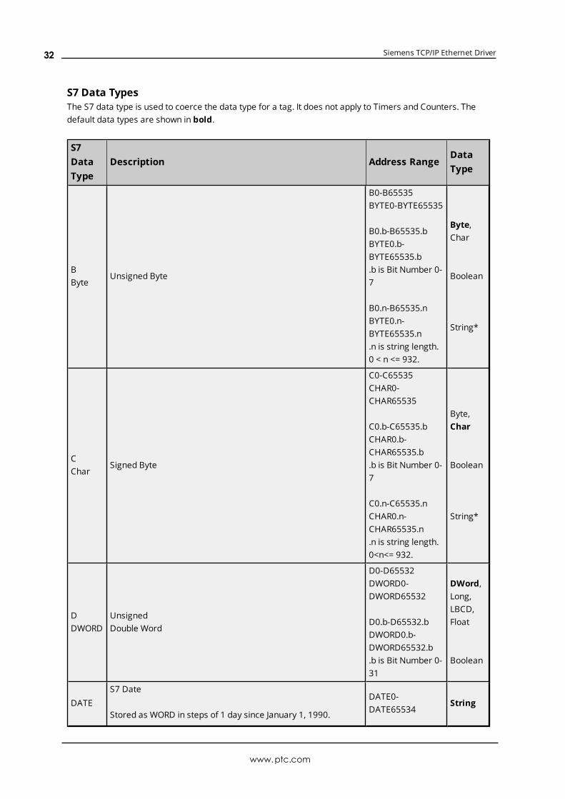
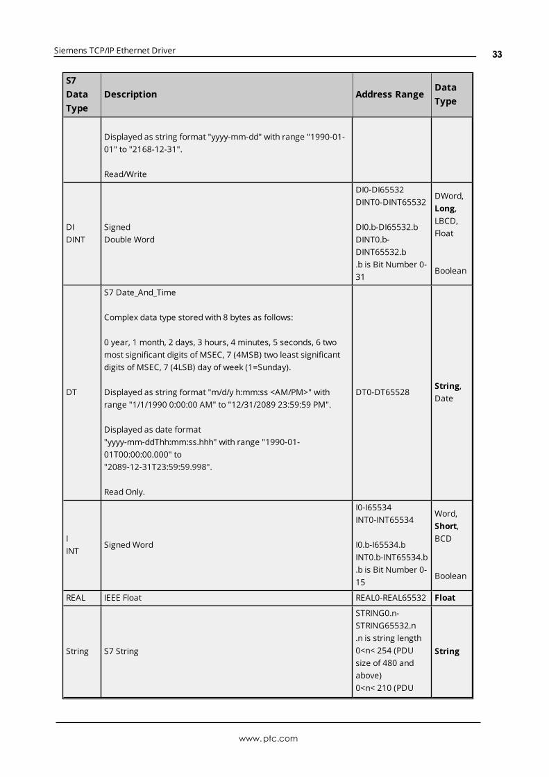
S7 Data TypesThe S7 data type is used to coerce the data type for a tag. It does not apply to Timers and Counters. Thedefault data types are shown in bold.
S7DataType
Description Address RangeDataType
BByte
Unsigned Byte
B0-B65535BYTE0-BYTE65535
B0.b-B65535.bBYTE0.b-BYTE65535.b.b is Bit Number 0-7
B0.n-B65535.nBYTE0.n-BYTE65535.n.n is string length.0 < n <= 932.
Byte,Char
Boolean
String*
CChar
Signed Byte
C0-C65535CHAR0-CHAR65535
C0.b-C65535.bCHAR0.b-CHAR65535.b.b is Bit Number 0-7
C0.n-C65535.nCHAR0.n-CHAR65535.n.n is string length.0<n<= 932.
Byte,Char
Boolean
String*
DDWORD
UnsignedDouble Word
D0-D65532DWORD0-DWORD65532
D0.b-D65532.bDWORD0.b-DWORD65532.b.b is Bit Number 0-31
DWord,Long,LBCD,Float
Boolean
DATES7 Date
Stored as WORD in steps of 1 day since January 1, 1990.
DATE0-DATE65534
String
www.ptc.com
32
Siemens TCP/IP Ethernet Driver
S7DataType
Description Address RangeDataType
Displayed as string format "yyyy-mm-dd" with range "1990-01-01" to "2168-12-31".
Read/Write
DIDINT
SignedDouble Word
DI0-DI65532DINT0-DINT65532
DI0.b-DI65532.bDINT0.b-DINT65532.b.b is Bit Number 0-31
DWord,Long,LBCD,Float
Boolean
DT
S7 Date_And_Time
Complex data type stored with 8 bytes as follows:
0 year, 1 month, 2 days, 3 hours, 4 minutes, 5 seconds, 6 twomost significant digits of MSEC, 7 (4MSB) two least significantdigits of MSEC, 7 (4LSB) day of week (1=Sunday).
Displayed as string format "m/d/y h:mm:ss <AM/PM>" withrange "1/1/1990 0:00:00 AM" to "12/31/2089 23:59:59 PM".
Displayed as date format"yyyy-mm-ddThh:mm:ss.hhh" with range "1990-01-01T00:00:00.000" to"2089-12-31T23:59:59.998".
Read Only.
DT0-DT65528String,Date
IINT
SignedWord
I0-I65534INT0-INT65534
I0.b-I65534.bINT0.b-INT65534.b.b is Bit Number 0-15
Word,Short,BCD
Boolean
REAL IEEE Float REAL0-REAL65532 Float
String S7 String
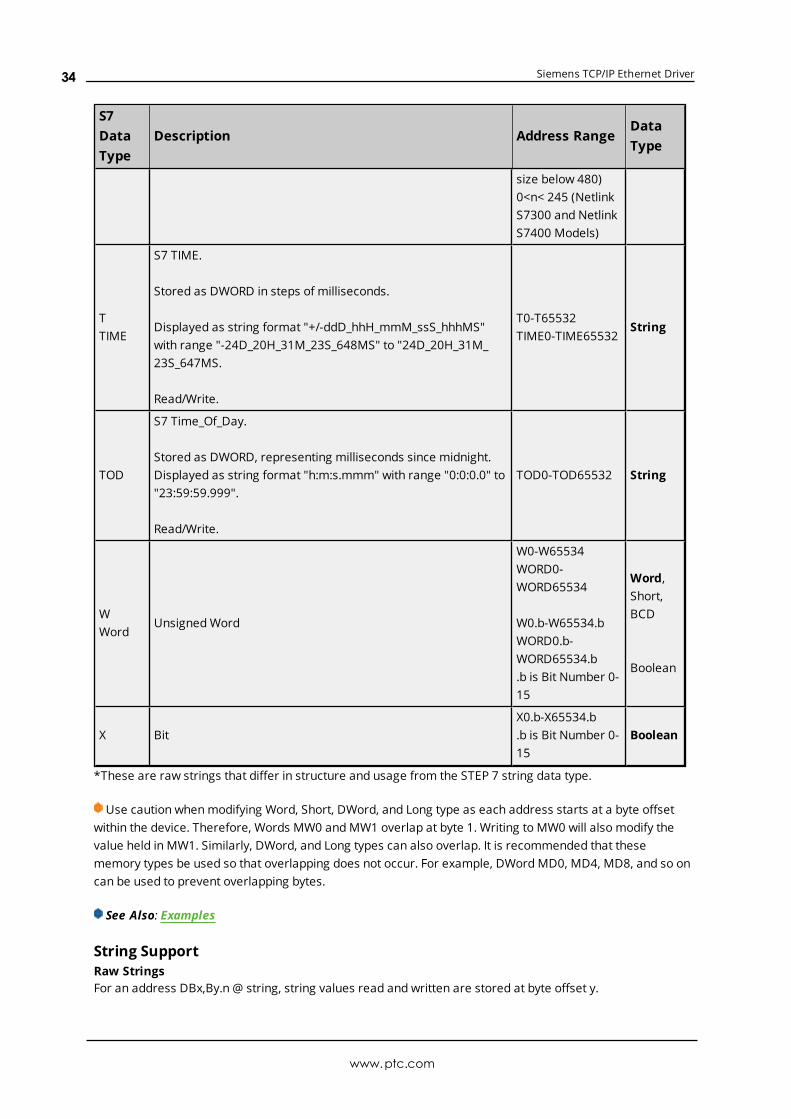
STRING0.n-STRING65532.n.n is string length0<n< 254 (PDUsize of 480 andabove)0<n< 210 (PDU
String
www.ptc.com
33
Siemens TCP/IP Ethernet Driver
S7DataType
Description Address RangeDataType
size below 480)0<n< 245 (NetlinkS7300 and NetlinkS7400 Models)
TTIME
S7 TIME.
Stored as DWORD in steps of milliseconds.
Displayed as string format "+/-ddD_hhH_mmM_ssS_hhhMS"with range "-24D_20H_31M_23S_648MS" to "24D_20H_31M_23S_647MS.
Read/Write.
T0-T65532TIME0-TIME65532
String
TOD
S7 Time_Of_Day.
Stored as DWORD, representing milliseconds since midnight.Displayed as string format "h:m:s.mmm" with range "0:0:0.0" to"23:59:59.999".
Read/Write.
TOD0-TOD65532 String
WWord
UnsignedWord
W0-W65534WORD0-WORD65534
W0.b-W65534.bWORD0.b-WORD65534.b.b is Bit Number 0-15
Word,Short,BCD
Boolean
X BitX0.b-X65534.b.b is Bit Number 0-15
Boolean
*These are raw strings that differ in structure and usage from the STEP 7 string data type.
Use caution whenmodifying Word, Short, DWord, and Long type as each address starts at a byte offsetwithin the device. Therefore, Words MW0 andMW1 overlap at byte 1. Writing to MW0 will also modify thevalue held in MW1. Similarly, DWord, and Long types can also overlap. It is recommended that thesememory types be used so that overlapping does not occur. For example, DWordMD0, MD4, MD8, and so oncan be used to prevent overlapping bytes.
See Also: Examples
String SupportRaw StringsFor an address DBx,By.n @ string, string values read and written are stored at byte offset y.
www.ptc.com
34
Siemens TCP/IP Ethernet Driver
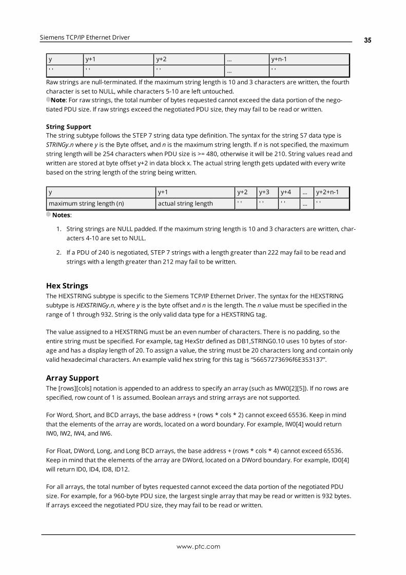
y y+1 y+2 ... y+n-1
' ' ' ' ' ' ... ' '
Raw strings are null-terminated. If the maximum string length is 10 and 3 characters are written, the fourthcharacter is set to NULL, while characters 5-10 are left untouched.Note: For raw strings, the total number of bytes requested cannot exceed the data portion of the nego-
tiated PDU size. If raw strings exceed the negotiated PDU size, they may fail to be read or written.
String SupportThe string subtype follows the STEP 7 string data type definition. The syntax for the string S7 data type isSTRINGy.n where y is the Byte offset, and n is the maximum string length. If n is not specified, the maximumstring length will be 254 characters when PDU size is >= 480, otherwise it will be 210. String values read andwritten are stored at byte offset y+2 in data block x. The actual string length gets updated with every writebased on the string length of the string being written.
y y+1 y+2 y+3 y+4 ... y+2+n-1
maximum string length (n) actual string length ' ' ' ' ' ' ... ' '
Notes:
1. String strings are NULL padded. If the maximum string length is 10 and 3 characters are written, char-acters 4-10 are set to NULL.
2. If a PDU of 240 is negotiated, STEP 7 strings with a length greater than 222 may fail to be read andstrings with a length greater than 212 may fail to be written.
Hex StringsThe HEXSTRING subtype is specific to the Siemens TCP/IP Ethernet Driver. The syntax for the HEXSTRINGsubtype is HEXSTRINGy.n, where y is the byte offset and n is the length. The n value must be specified in therange of 1 through 932. String is the only valid data type for a HEXSTRING tag.
The value assigned to a HEXSTRING must be an even number of characters. There is no padding, so theentire string must be specified. For example, tag HexStr defined as DB1,STRING0.10 uses 10 bytes of stor-age and has a display length of 20. To assign a value, the string must be 20 characters long and contain onlyvalid hexadecimal characters. An example valid hex string for this tag is “56657273696f6E353137”.
Array SupportThe [rows][cols] notation is appended to an address to specify an array (such as MW0[2][5]). If no rows arespecified, row count of 1 is assumed. Boolean arrays and string arrays are not supported.
For Word, Short, and BCD arrays, the base address + (rows * cols * 2) cannot exceed 65536. Keep in mindthat the elements of the array are words, located on a word boundary. For example, IW0[4] would returnIW0, IW2, IW4, and IW6.
For Float, DWord, Long, and Long BCD arrays, the base address + (rows * cols * 4) cannot exceed 65536.Keep in mind that the elements of the array are DWord, located on a DWord boundary. For example, ID0[4]will return ID0, ID4, ID8, ID12.
For all arrays, the total number of bytes requested cannot exceed the data portion of the negotiated PDUsize. For example, for a 960-byte PDU size, the largest single array that may be read or written is 932 bytes.If arrays exceed the negotiated PDU size, they may fail to be read or written.
www.ptc.com
35
Siemens TCP/IP Ethernet Driver
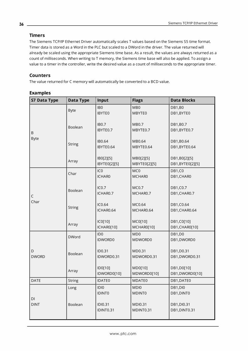
TimersThe Siemens TCP/IP Ethernet Driver automatically scales T values based on the Siemens S5 time format.Timer data is stored as a Word in the PLC but scaled to a DWord in the driver. The value returned willalready be scaled using the appropriate Siemens time base. As a result, the values are always returned as acount of milliseconds. When writing to T memory, the Siemens time base will also be applied. To assign avalue to a timer in the controller, write the desired value as a count of milliseconds to the appropriate timer.
CountersThe value returned for C memory will automatically be converted to a BCD value.
ExamplesS7 Data Type Data Type Input Flags Data Blocks
BByte
Byte
Boolean
String
Array
IB0IBYTE0
IB0.7IBYTE0.7
IB0.64IBYTE0.64
IB0[2][5]IBYTE0[2][5]
MB0MBYTE0
MB0.7MBYTE0.7
MB0.64MBYTE0.64
MB0[2][5]MBYTE0[2][5]
DB1,B0DB1,BYTE0
DB1,B0.7DB1,BYTE0.7
DB1,B0.64DB1,BYTE0.64
DB1,B0[2][5]DB1,BYTE0[2][5]
CChar
Char
Boolean
String
Array
IC0ICHAR0
IC0.7ICHAR0.7
IC0.64ICHAR0.64
IC0[10]ICHAR0[10]
MC0MCHAR0
MC0.7MCHAR0.7
MC0.64MCHAR0.64
MC0[10]MCHAR0[10]
DB1,C0DB1,CHAR0
DB1,C0.7DB1,CHAR0.7
DB1,C0.64DB1,CHAR0.64
DB1,C0[10]DB1,CHAR0[10]
DDWORD
DWord
Boolean
Array
ID0IDWORD0
ID0.31IDWORD0.31
ID0[10]IDWORD0[10]
MD0MDWORD0
MD0.31MDWORD0.31
MD0[10]MDWORD0[10]
DB1,D0DB1,DWORD0
DB1,D0.31DB1,DWORD0.31
DB1,D0[10]DB1,DWORD0[10]
DATE String IDATE0 MDATE0 DB1,DATE0
DIDINT
Long
Boolean
IDI0IDINT0
IDI0.31IDINT0.31
MDI0MDINT0
MDI0.31MDINT0.31
DB1,DI0DB1,DINT0
DB1,DI0.31DB1,DINT0.31
www.ptc.com
36
Siemens TCP/IP Ethernet Driver
S7 Data Type Data Type Input Flags Data Blocks
ArrayIDI0[4][3]IDINT0[4][3]
MDI0[4][3]MDINT0[4][3]
DB1,DI0[4][3]DB1,DINT0[4][3]
DTStringDate
IDT0IDT8
MDT0MDT8
DB1,DT0DB1,DT8
IINT
Short
Boolean
Array
II0IINT0
II0.15IINT0.15
II0[5][2]IINT0[5][2]
MI0MINT0
MI0.15MINT0.15
MI0[5][2]MINT0[5][2]
DB1,I0DB1,INT0
DB1,I0.15DB1,INT0.15
DB1,I0[5][2]DB1,INT0[5][2]
REALFloat
Array
IREAL0
IREAL0[10]
MREAL0
MREAL0[10]
DB1,REAL0
DB1,REAL0[10]
String String ISTRING0.10 MSTRING0.10 DB1,STRING0.10
TOD String ITOD0 MTOD0 DB1,TOD0
TTIME
StringIT0ITIME4
MT0MTIME4
DB1,T0DB1,TIME4
WWord
Word
Boolean
Array
IW0IWORD0
IW0.15IWORD0.15
IW0[10]IWORD0[10]
MW0MWORD0
MW0.15MWORD0.15
MW0[10]MWORD0[10]
DB1,W0DB1,WORD0
DB1,W0.15DB1,WORD0.15
DB1,W0[10]DB1,WORD0[10]
X BooleanIX0.7IX0[10]
MX0.7MX0[10]
DB1,X0.7DB1,X0[10]
Note: The offset for an atomic type tag in a data block is denoted by the column "Address" in Step 7, asshown above. This offset is denoted by the column "Offset" in the Siemens TIA Portal programming envir-onment.
Legacy S7-300/400 Item SyntaxThe default data types for dynamically defined tags are shown in bold.For preferred item syntax, refer to Standard S7-300/400/1200/1500 Item Syntax.
Address Type Range Type Access
Discrete Inputs
I0.b-I65535.b.b is Bit Number 0-7
IB0-IB65535IW0-IW65534IW:KT0-IW:KT65534IW:KC0-IW:KC65534
Boolean
Byte, Char, String**Word, Short, BCDDWord, LongWord, Short
Read/Write
Read/WriteRead/WriteRead/WriteRead/Write
www.ptc.com
37

Siemens TCP/IP Ethernet Driver
Address Type Range Type Access
ID0-ID65532DWord, Long, LBCD,Float
Read/Write
Discrete Inputs
E0.b-E65535.b.b is Bit Number 0-7
EB0-EB65535**EW0-EW65534EW:KT0-EW:KT65534EW:KC0-EW:KC65534ED0-ED65532
Boolean
Byte, Char, String**Word, Short, BCDDWord, LongWord, ShortDWord, Long, LBCD,Float
Read/Write
Read/WriteRead/WriteRead/WriteRead/WriteRead/Write
Note: I and E access the same memory area.
Discrete Outputs
Q0.b-Q65535.b.b is Bit Number 0-7
QB0-QB65535QW0-QW65534QW:KT0-QW:KT65534QW:KC0-QW:KC65534QD0-QD65532
Boolean
Byte, Char, String**Word, Short, BCDDWord, LongWord, ShortDWord, Long, LBCD,Float
Read/Write
Read/WriteRead/WriteRead/WriteRead/WriteRead/Write
Discrete Outputs
A0.b-A65535.b.b is Bit Number 0-7
AB0-AB65535AW0-AW65534AW:KT0-AW:KT65534AW:KC0-AW:KC65534AD0-AD65532
Boolean
Byte, Char, String**Word, Short, BCDDWord, LongWord, ShortDWord, Long, LBCD,Float
Read/Write
Read/WriteRead/WriteRead/WriteRead/WriteRead/Write
Note: Q and A access the same memory area.
Peripheral Inputs
PI0.b-PI65535.b.b is Bit Number 0-7
PIB0-PIB65535PIW0-PIW65534PIW:KT0-PIW:KT65534PIW:KC0-PIW:KC65534PID0-PID65532
Boolean
Byte, Char, String**Word, Short, BCDDWord, LongWord, ShortDWord, Long, LBCD,Float
Read Only
Read OnlyRead OnlyRead OnlyRead OnlyRead Only
Peripheral Inputs
PE0.b-PE65535.b.b is Bit Number 0-7
PEB0-PEB65535**PEW0-PEW65534PEW:KT0-PEW:KT65534PEW:KC0-PEW:KC65534
Boolean
Byte, Char, String**Word, Short, BCDDWord, LongWord, Short
Read Only
Read OnlyRead OnlyRead OnlyRead Only
www.ptc.com
38
Siemens TCP/IP Ethernet Driver
Address Type Range Type Access
PED0-PED65532DWord, Long, LBCD,Float
Read Only
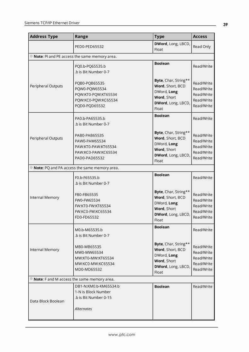
Note: PI and PE access the same memory area.
Peripheral Outputs
PQ0.b-PQ65535.b.b is Bit Number 0-7
PQB0-PQB65535PQW0-PQW65534PQW:KT0-PQW:KT65534PQW:KC0-PQW:KC65534PQD0-PQD65532
Boolean
Byte, Char, String**Word, Short, BCDDWord, LongWord, ShortDWord, Long, LBCD,Float
Read/Write
Read/WriteRead/WriteRead/WriteRead/WriteRead/Write
Peripheral Outputs
PA0.b-PA65535.b.b is Bit Number 0-7
PAB0-PAB65535PAW0-PAW65534PAW:KT0-PAW:KT65534PAW:KC0-PAW:KC65534PAD0-PAD65532
Boolean
Byte, Char, String**Word, Short, BCDDWord, LongWord, ShortDWord, Long, LBCD,Float
Read/Write
Read/WriteRead/WriteRead/WriteRead/WriteRead/Write
Note: PQ and PA access the same memory area.
Internal Memory
F0.b-F65535.b.b is Bit Number 0-7
FB0-FB65535FW0-FW65534FW:KT0-FW:KT65534FW:KC0-FW:KC65534FD0-FD65532
Boolean
Byte, Char, String**Word, Short, BCDDWord, LongWord, ShortDWord, Long, LBCD,Float
Read/Write
Read/WriteRead/WriteRead/WriteRead/WriteRead/Write
Internal Memory
M0.b-M65535.b.b is Bit Number 0-7
MB0-MB65535MW0-MW65534MW:KT0-MW:KT65534MW:KC0-MW:KC65534MD0-MD65532
Boolean
Byte, Char, String**Word, Short, BCDDWord, LongWord, ShortDWord, Long, LBCD,Float
Read/Write
Read/WriteRead/WriteRead/WriteRead/WriteRead/Write
Note: F andM access the same memory area.
Data Block Boolean
DB1-N:KM0.b-KM65534.b1-N is Block Number.b is Bit Number 0-15
Alternates
Boolean Read/Write
www.ptc.com
39
Siemens TCP/IP Ethernet Driver
Address Type Range Type Access
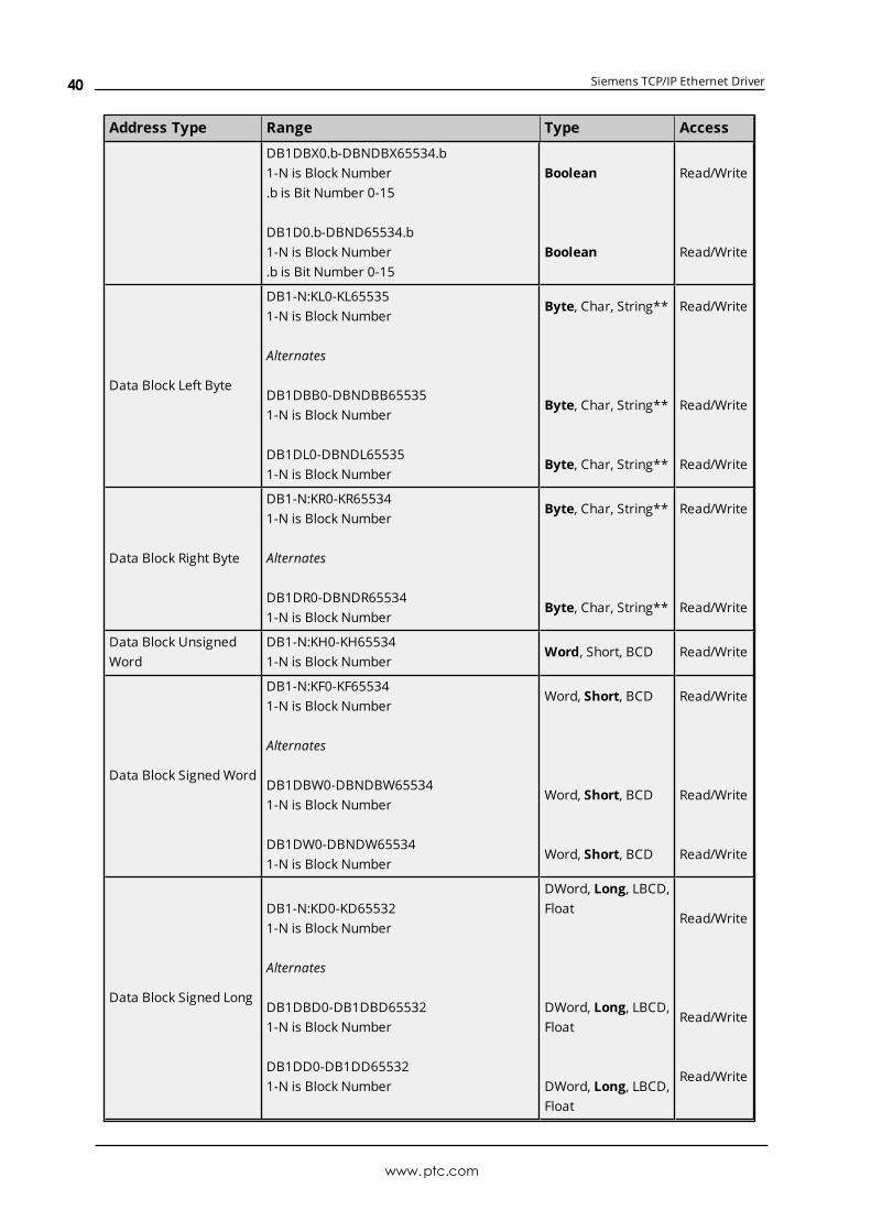
DB1DBX0.b-DBNDBX65534.b1-N is Block Number.b is Bit Number 0-15
DB1D0.b-DBND65534.b1-N is Block Number.b is Bit Number 0-15
Boolean
Boolean
Read/Write
Read/Write
Data Block Left Byte
DB1-N:KL0-KL655351-N is Block Number
Alternates
DB1DBB0-DBNDBB655351-N is Block Number
DB1DL0-DBNDL655351-N is Block Number
Byte, Char, String**
Byte, Char, String**
Byte, Char, String**
Read/Write
Read/Write
Read/Write
Data Block Right Byte
DB1-N:KR0-KR655341-N is Block Number
Alternates
DB1DR0-DBNDR655341-N is Block Number
Byte, Char, String**
Byte, Char, String**
Read/Write
Read/Write
Data Block UnsignedWord
DB1-N:KH0-KH655341-N is Block Number
Word, Short, BCD Read/Write
Data Block SignedWord
DB1-N:KF0-KF655341-N is Block Number
Alternates
DB1DBW0-DBNDBW655341-N is Block Number
DB1DW0-DBNDW655341-N is Block Number
Word, Short, BCD
Word, Short, BCD
Word, Short, BCD
Read/Write
Read/Write
Read/Write
Data Block Signed Long
DB1-N:KD0-KD655321-N is Block Number
Alternates
DB1DBD0-DB1DBD655321-N is Block Number
DB1DD0-DB1DD655321-N is Block Number
DWord, Long, LBCD,Float
DWord, Long, LBCD,Float
DWord, Long, LBCD,Float
Read/Write
Read/Write
Read/Write
www.ptc.com
40
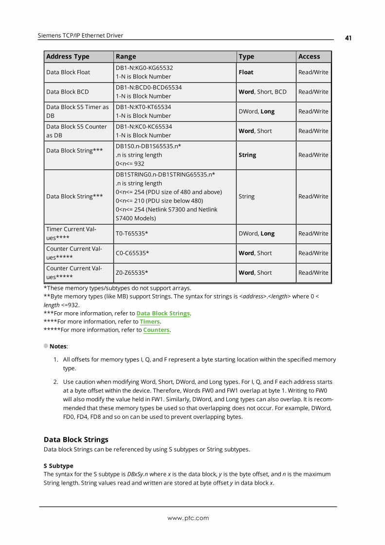
Siemens TCP/IP Ethernet Driver
Address Type Range Type Access
Data Block FloatDB1-N:KG0-KG655321-N is Block Number
Float Read/Write
Data Block BCDDB1-N:BCD0-BCD655341-N is Block Number
Word, Short, BCD Read/Write
Data Block S5 Timer asDB
DB1-N:KT0-KT655341-N is Block Number
DWord, Long Read/Write
Data Block S5 Counteras DB
DB1-N:KC0-KC655341-N is Block Number
Word, Short Read/Write
Data Block String***DB1S0.n-DB1S65535.n*.n is string length0<n<= 932
String Read/Write
Data Block String***
DB1STRING0.n-DB1STRING65535.n*.n is string length0<n<= 254 (PDU size of 480 and above)0<n<= 210 (PDU size below 480)0<n<= 254 (Netlink S7300 and NetlinkS7400 Models)
String Read/Write
Timer Current Val-ues****
T0-T65535* DWord, Long Read/Write
Counter Current Val-ues*****
C0-C65535* Word, Short Read/Write
Counter Current Val-ues*****
Z0-Z65535* Word, Short Read/Write
*These memory types/subtypes do not support arrays.**Byte memory types (like MB) support Strings. The syntax for strings is <address>.<length> where 0 <length <=932.***For more information, refer to Data Block Strings.****For more information, refer to Timers.*****For more information, refer to Counters.
Notes:
1. All offsets for memory types I, Q, and F represent a byte starting location within the specified memorytype.
2. Use caution whenmodifying Word, Short, DWord, and Long types. For I, Q, and F each address startsat a byte offset within the device. Therefore, Words FW0 and FW1 overlap at byte 1. Writing to FW0will also modify the value held in FW1. Similarly, DWord, and Long types can also overlap. It is recom-mended that these memory types be used so that overlapping does not occur. For example, DWord,FD0, FD4, FD8 and so on can be used to prevent overlapping bytes.
Data Block StringsData block Strings can be referenced by using S subtypes or String subtypes.
S SubtypeThe syntax for the S subtype is DBxSy.n where x is the data block, y is the byte offset, and n is the maximumString length. String values read and written are stored at byte offset y in data block x.
www.ptc.com
41
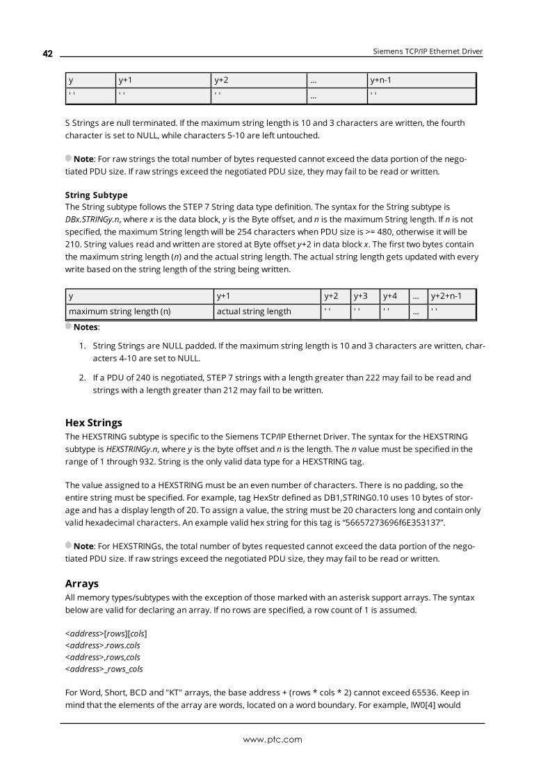
Siemens TCP/IP Ethernet Driver
y y+1 y+2 ... y+n-1
' ' ' ' ' ' ... ' '
S Strings are null terminated. If the maximum string length is 10 and 3 characters are written, the fourthcharacter is set to NULL, while characters 5-10 are left untouched.
Note: For raw strings the total number of bytes requested cannot exceed the data portion of the nego-tiated PDU size. If raw strings exceed the negotiated PDU size, they may fail to be read or written.
String SubtypeThe String subtype follows the STEP 7 String data type definition. The syntax for the String subtype isDBx.STRINGy.n, where x is the data block, y is the Byte offset, and n is the maximum String length. If n is notspecified, the maximum String length will be 254 characters when PDU size is >= 480, otherwise it will be210. String values read and written are stored at Byte offset y+2 in data block x. The first two bytes containthe maximum string length (n) and the actual string length. The actual string length gets updated with everywrite based on the string length of the string being written.
y y+1 y+2 y+3 y+4 ... y+2+n-1
maximum string length (n) actual string length ' ' ' ' ' ' ... ' '
Notes:
1. String Strings are NULL padded. If the maximum string length is 10 and 3 characters are written, char-acters 4-10 are set to NULL.
2. If a PDU of 240 is negotiated, STEP 7 strings with a length greater than 222 may fail to be read andstrings with a length greater than 212 may fail to be written.
Hex StringsThe HEXSTRING subtype is specific to the Siemens TCP/IP Ethernet Driver. The syntax for the HEXSTRINGsubtype is HEXSTRINGy.n, where y is the byte offset and n is the length. The n value must be specified in therange of 1 through 932. String is the only valid data type for a HEXSTRING tag.
The value assigned to a HEXSTRING must be an even number of characters. There is no padding, so theentire string must be specified. For example, tag HexStr defined as DB1,STRING0.10 uses 10 bytes of stor-age and has a display length of 20. To assign a value, the string must be 20 characters long and contain onlyvalid hexadecimal characters. An example valid hex string for this tag is “56657273696f6E353137”.
Note: For HEXSTRINGs, the total number of bytes requested cannot exceed the data portion of the nego-tiated PDU size. If raw strings exceed the negotiated PDU size, they may fail to be read or written.
ArraysAll memory types/subtypes with the exception of those marked with an asterisk support arrays. The syntaxbelow are valid for declaring an array. If no rows are specified, a row count of 1 is assumed.
<address>[rows][cols]<address>.rows.cols<address>,rows,cols<address>_rows_cols
For Word, Short, BCD and "KT" arrays, the base address + (rows * cols * 2) cannot exceed 65536. Keep inmind that the elements of the array are words, located on a word boundary. For example, IW0[4] would
www.ptc.com
42

Siemens TCP/IP Ethernet Driver
return IW0, IW2, IW4, and IW6. "KT" subtypes fall into the 16-bit category because the data stored in the PLCis contained within a Word. For more information, refer to Timers.
For Float, DWord, Long, and Long BCD arrays (excluding "KT" subtypes), the base address + (rows * cols * 4)cannot exceed 65536. Keep in mind that the elements of the array are DWord, located on a DWord bound-ary. For example, ID0[4] will return ID0, ID4, ID8, ID12.
For all arrays, the total number of bytes being requested cannot exceed the data portion of the negotiatedPDU size. For example, for a 960-byte PDU size, the largest single array that may be read or written is 932bytes. If arrays exceed the negotiated PDU size, they may fail to be read or written.
KL vs. KR vs. DBBKL and KR determine whether the left byte or right byte of the data block word is returned.
Value 8 9 A B C
Byte 0 1 2 3 4
The following examples are from the table above.
Example 1DB1:KH0=0x89DB1:KL0=0x8DB1:KR0=0x9DB1DBB0=0x8
Example 2DB1:KH1=0x9ADB1:KL1=0x9DB1:KR1=0xADB1DBB1=0x9
TimersThe Siemens TCP/IP Ethernet Driver automatically scales T and KT values based on the Siemens S5 timeformat. Timer data is stored as a Word in the PLC but scaled to a DWord in the driver. The value returned foreither a T or KT memory type will already be scaled using the appropriate Siemens time base. As a result,the values are always returned as a count of milliseconds. When writing to T or KT memory types, theSiemens time base will also be applied. To assign a value to a timer in the controller, write the desired valueas a count of milliseconds to the appropriate timer.
CountersThe value returned for either C or KC memory type will automatically be converted to a BCD value. DB1:KH0@ BCD=DB1:KC0 @ Word.
Examples
l To access bit 3 of internal memory F20, declare an address as follows: F20.3
l To access data block 5 as wordmemory at byte 30, declare an address as follows: DB5:KH30
l To access data block 2 byte 20 and bit 7, declare an address as follows: DB2:KM20.7
l To access data block 1 as left byte memory at byte 10, declare an address as follows: DB1:KL10
www.ptc.com
43

Siemens TCP/IP Ethernet Driver
l To access internal memory F20 as a DWORD, declare an address as follows: FD20
l To access Input memory I10 as a Word, declare an address as follows: IW10
Note: The offset for an atomic type tag in a data block is denoted by the column "Address" in Step 7, asshown above. This offset is denoted by the column "Offset" in the Siemens TIA Portal programming envir-onment.
www.ptc.com
44
Siemens TCP/IP Ethernet Driver
Event Log MessagesThe following information concerns messages posted to the Event Log pane in the main user interface. Con-sult the server help on filtering and sorting the Event Log detail view. Server help contains many commonmessages, so should also be searched. Generally, the type of message (informational, warning) andtroubleshooting information is provided whenever possible.
Reason = 'Frame contains errors'.Error Type:Warning
Possible Cause:
1. An unexpected frame was received. The response code may be incorrect.
2. The frame sequence is out of order.
Possible Solution:Cable noise may cause distortion in the frame, resulting in erroneous data or dropped frames. Verify thecabling between the PC and the PLC device.
See Also:
1. Error Matrix
2. Error Codes
Reason = 'Device returned transport error'. Error code = <error>.Error Type:Warning
Possible Cause:An RFC1006 (ISO over TCP/IP) error occurred. This is the portion of the packet that encapsulates the S7 Mes-saging packet.
Possible Solution:Follow guidance from the rest of the error message or contact Technical Support.
Note:No protocol or data access errors can occur for this operation.
See Also:
1. Error Matrix
2. Error Codes
www.ptc.com
45

Siemens TCP/IP Ethernet Driver
Reason = 'Device returned protocol error'. Error class = <class>, Error code= <error>.Error Type:Warning
Possible Cause:
1. An S7 Messaging error occurred. This can occur if a portion is malformed or contains incorrectpacket lengths.
2. The tag is too large to be read or written with the currently negotiated PDU.
Possible Solution:
1. Follow guidance from the rest of the error message or contact Technical Support.
2. Adjust the size of the tag, or check the Maximum PDU Size device property.
See Also:
1. Error Matrix
2. Error Codes
3. Device Properties – S7 Comm Parameters
Reason = 'Device returned data access error'. Error code = <error>.Error Type:Warning
Possible Cause:A requested address may be out of range or referenced incorrectly.
Possible Solution:
1. Verify the range is correct and correctly referenced.
2. Follow guidance from the rest of the error message or contact Technical Support.
See Also:
1. Error Matrix
2. Error Codes
Reason = 'Device is not responding'.Error Type:Warning
Possible Cause:
www.ptc.com
46
Siemens TCP/IP Ethernet Driver
1. The connection between the device and the host PC is invalid.
2. The named device may have an incorrect IP address assigned.
3. The response from the device took longer to receive than the amount of time specified in the"Request Timeout" device setting.
4. The device CPU load is too high.
Possible Solution:
1. Verify the cabling between the PC and the PLC device.
2. Verify the IP address for the named device matches the actual device.
3. Decrease the tag group scan rate to reduce the load on the PLC CPU.
4. Increase the values for properties: Request Timeout, Scan Cycle Load from Communication, and/orScan Cycle Monitoring Time.
See Also:Error Matrix
Reason = 'Unknown error occurred'.Error Type:Warning
Possible Cause:Process could not complete.
Possible Solution:Follow guidance from the rest of the error message or retry the process.
See Also:Error Matrix
Reason = NetLink returned error. Error code = <error>.Error Type:Warning
Possible Cause:An error was returned from the PLC or NetLink adapter.
Possible Solution:
1. If error code is 0x11, an incorrect MPI ID may be set. Determine the MPI ID through which com-munications are occurring and enter it in the MPI ID device property field.
2. If error code is 0x87, the requested data may be out of range for the device. Verify the deviceaddress limits and correct the tag references.
www.ptc.com
47
Siemens TCP/IP Ethernet Driver
See Also:
1. Error Matrix
2. Error Codes
Failed to resolve host. | Host = '<host name>'.Error Type:Warning
Possible Cause:
1. The named device may have been assigned an incorrect IP address.
2. Communication with the host failed. Connectionmay have been lost, a port conflict occurred, orsome communication parameter is not valid.
Possible Solution:
1. Verify the IP address given to the named device matches that of the actual device.
2. Verify or correct connections, port number, MPI ID, and other communication parameters.
Auto-generated tag names and descriptions may not appear as expecteddue to string conversion error.Error Type:Warning
Possible Cause:The Unicode character conversion failed.
Possible Solution:Verify that the Step 7 language file is present and reflects a character set that can display the Step 7 tag andcomment strings.
A required code page is unavailable on this machine. Tag generation mayfail or tag names and descriptions may not appear as expected. |Required code page = <page>.Error Type:Warning
Possible Cause:
1. The computer is not configured with support for the specified Windows code page specified.
2. The language file was not found.
Possible Solution:
www.ptc.com
48
Siemens TCP/IP Ethernet Driver
1. Install any language packs necessary for displaying the Windows code page character set.
2. Try again on a computer that supports the Windows code page specified.
3. Modify the Step 7 project to generate a Language file.
Note:When Language file was not found the value of required code page will be: 0.
Unable to load the Step 7 language file.Error Type:Warning
Possible Cause:The Step 7 language file is altered or corrupt.
Possible Solution:Verify that the Step 7 project is not corrupt and can be opened in Simatic Step 7.
Memory exception reading the Step 7 language file.Error Type:Warning
Possible Cause:The operating system has insufficient memory to read the Step 7 language file.
Possible Solution:Ensure that the system resources are adequate for all applications running on the computer.
Step 7 language file failed to open. | OS error = '<error>'.Error Type:Warning
Possible Cause:
1. The Step 7 language file is altered or corrupt.
2. The language file is missing.
Possible Solution:
1. Verify that the Step 7 project is not corrupt and can be opened in Simatic Step 7.
2. Modify the Step 7 project to generate a language file.
www.ptc.com
49
Siemens TCP/IP Ethernet Driver
Tag generation failure. | Data block name = '<block name>', data blocknumber = <block number>.Error Type:Warning
Possible Cause:An unexpected data type or other issue occurred during the parsing of the Step 7 project for the specifieddata block.
Possible Solution:Compare the tags that were automatically generated with those in the project for the specified data block todetermine which tag caused the incomplete generation. Correct issues with the block and retry.
See Also:Error Codes
Created tag in group due to internal block size. | Tag address ='<address>', tag name = '<name>', group name = '<name>'.Error Type:Warning
Possible Cause:While parsing the data blocks of the Step 7 project for automatic tag generation, an array variable wasencountered that exceeds the internal block size. Although all individual array element tags generate asexpected, the array tag itself is generated with a dimension that allows it to fit within the block size.
Possible Solution:To use array tags and not the individual array element tags, determine the address where the array tagends, thenmanually generate another tag to address the remainder of the array. For example, if data block1 begins with an array of 250 REAL, there would be 250 array element tags with addresses DB1,REAL0;DB1,REAL4;... DB1, REAL992; DB1,REAL996. Because the size of the array exceeds the maximum data pay-load of 932 bytes, the array tag would only be created with 233 dimensions (DB1,REAL0[233]). The array tagdoes not provide the client with the data for the last 17 elements. If the client wants to use array tags and notthe individual array element tags, another tag with the address "DB1,REAL932[17]" must be created. Thiswarning message only occurs for tags of the first element of the complex type array during automatic taggeneration for arrays of complex types (such as structures, user-defined types, function blocks, or systemfunction blocks).
Tag not created because arrays are not supported with specified datatype. | Tag name = '<name>', group name = '<name>', data type = '<type>'.
Error Type:Warning
Possible Cause:
www.ptc.com
50
Siemens TCP/IP Ethernet Driver
1. A tag address that has been specified dynamically has been assigned an invalid data type.
2. While parsing the data blocks of the Step 7 project for automatic tag generation, an array variablewas encountered with a data type for which the driver does not support arrays.
Possible Solution:
1. Modify the requested data type in the client application.
2. The client must access the data using the array element tags that were generated. Variables with theStep 7 data types of DATE, DATE_AND_TIME, STRING, TIME, and TIME_OF_DAY generate tags with thestring data type (for which arrays are not supported). During automatic tag generation for arrays ofcomplex types (such as structures, user-defined types, function blocks, or system function blocks),this warning message only occurs for tags of the first element of the complex type array.
Unable to connect to device. |Error Type:Warning
Possible Cause:
1. An RFC1006 error (ISO over TCP/IP) occurred. This is the portion of the packet that encapsulates theS7 Messaging packet.
2. The device's CPU work load is too high.
3. This portion is malformed or contains incorrect packet lengths.
Possible Solution:
1. Cable noise may cause distortion in the frame, resulting in erroneous data or dropped frames. Verifythe cabling between the PC and the PLC device.
2. Reduce network traffic or increase the Request Timeout and/or Fail After Attempt count.
3. Decrease the tag group Scan Rate to reduce the load on the PLC CPU.
4. Increase the values for properties: Scan Cycle Load from Communication and Scan Cycle MonitoringTime.
See Also:Error Matrix
Unable to establish association with device. |Error Type:Warning
Possible Cause:
www.ptc.com
51
Siemens TCP/IP Ethernet Driver
1. An S7 Messaging error occurred. This will occur if this portion is malformed or contains incorrectpacket lengths.
2. An RFC1006 error (ISO over TCP/IP) occurred. This is the portion of the packet that encapsulates theS7 Messaging packet.
3. The TPDU response size is incorrect.
4. An unexpected frame was received. The response code may be incorrect.
5. The frame sequence is out of order.
6. The device CPU workload is too high.
Possible Solution:
1. Cable noise may cause distortion in the frame, resulting in erroneous data. It may also causedropped frames. Verify the cabling between the PC and the PLC device.
2. Reduce network traffic. If this error occurs frequently, increase the Request Timeout and/or Fail Afterattempt count.
3. If this error occurs frequently, decrease the tag group scan rate to reduce the work load on the PLC'sCPU.
4. Increase the Scan Cycle Load from Communication and Scan Cycle Monitoring Time.
See Also:Error Matrix
Unable to read from address on device. | Address = '<address>',Error Type:Warning
Possible Cause:
1. A data access error occurred. The requested address may be out of range or referenced incorrectly.
2. An S7 messaging error occurred. A portion is malformed or contains incorrect packet lengths.
3. A TCP/IP error occurred. A portion is malformed or contains incorrect packet lengths.
4. An attempt was made to read an array larger than the PDU size negotiated with the device.
Possible Solution:
1. Verify and correct the address range.
2. Verify and correct the packet format and length.
3. Verify and correct the communications configuration and connections.
4. Verify and correct the data type, values, and ranges.
5. Verify the device's address limits and correct the tag references causing the error.
www.ptc.com
52
Siemens TCP/IP Ethernet Driver
See Also:Error Matrix
Unable to read from address on device. Tag deactivated. | Address ='<address>',Error Type:Warning
Possible Cause:
1. A data access error occurred. The requested address may be out of range or referenced incorrectly.
2. An S7 Messaging error occurred. A portion is malformed or contains incorrect packet lengths.
3. A TCP/IP error occurred. A portion is malformed or contains incorrect packet lengths.
4. The device CPU work load is too high.
5. If the tag address references a TOD data type, the DWORD value may be larger than the number ofmilliseconds in a day. For example, 86400000.
6. If the error code=0x11, an incorrect MPI ID may be set.
7. If the error code=0x87, users may be accessing data out of range in the device.
Possible Solution:
1. Verify and correct the address range.
2. Verify and correct the packet format and length.
3. Verify and correct the communications configuration and connections.
4. Verify and correct the data type, values, and ranges.
5. Reduce network traffic or increase the Request Timeout and/or Fail After attempt count.
6. Decrease the tag group scan rate to reduce the workload on the PLC CPU.
7. Increase the Scan Cycle Load from Communication and Scan Cycle Monitoring Time.
8. Change the value in the device to a valid DWORD that can be converted to a time that is less than orequal to 23:59:59.999.
9. Determine the MPI ID in use for communications and re-enter it in the MPI ID Device Property field.
10. Verify the device's address limits and correct the tag references causing the error.
See Also:Error Matrix
Unable to read data from device. | Data block = '<block>', block start =<address>, block size = <size>,Error Type:
www.ptc.com
53
Siemens TCP/IP Ethernet Driver
Warning
Possible Cause:
1. A TCP/IP error occurred. A portion is malformed or contains incorrect packet lengths.
2. The device CPU work load is too high.
3. If the tag address references a TOD data type, the DWORD value may be larger than the number ofmilliseconds in a day. For example, 86400000.
4. An error was returned from the PLC or NetLink adapter.
5. Cable noise may cause distortion in the frame, resulting in erroneous data or dropped frames. Verifythe cabling between the PC and the PLC device.
6. If the error code=0x11, an incorrect MPI ID may be set.
7. If the error code=0x87, users may be accessing data out of range in the device.
Possible Solution:
1. Verify and correct the address range.
2. Verify and correct the packet format and length.
3. Verify and correct the communications configuration and connections.
4. Verify and correct the data type, values, and ranges.
5. Reduce network traffic or increase the Request Timeout and/or Fail After attempt count.
6. Decrease the tag group scan rate to reduce the workload on the PLC CPU.
7. Increase the Scan Cycle Load from Communication and Scan Cycle Monitoring Time.
8. Change the value in the device to a valid DWORD that can be converted to a time that is less than orequal to 23:59:59.999.
9. Determine the MPI ID in use for communications and re-enter it in the MPI ID Device Property field.
10. Verify the device's address limits and correct the tag references causing the error.
See Also:Error Matrix
Unable to read data from device. Block deactivated. | Data block ='<block>', block start = <address>, block size = <size>,Error Type:Warning
Possible Cause:
1. A TCP/IP error occurred. A portion is malformed or contains incorrect packet lengths.
2. The device CPU work load is too high.
www.ptc.com
54

Siemens TCP/IP Ethernet Driver
3. If the tag address references a TOD data type, the DWORD value may be larger than the number ofmilliseconds in a day. For example, 86400000.
4. An error was returned from the PLC or NetLink adapter.
5. Cable noise may cause distortion in the frame, resulting in erroneous data or dropped frames. Verifythe cabling between the PC and the PLC device.
6. If the error code=0x11, an incorrect MPI ID may be set.
7. If the error code=0x87, users may be accessing data out of range in the device.
Possible Solution:
1. Verify and correct the address range.
2. Verify and correct the packet format and length.
3. Verify and correct the communications configuration and connections.
4. Verify and correct the data type, values, and ranges.
5. Reduce network traffic or increase the Request Timeout and/or Fail After attempt count.
6. Decrease the tag group scan rate to reduce the workload on the PLC CPU.
7. Increase the Scan Cycle Load from Communication and Scan Cycle Monitoring Time.
8. Change the value in the device to a valid DWORD that can be converted to a time that is less than orequal to 23:59:59.999.
9. Determine the MPI ID in use for communications and re-enter it in the MPI ID Device Property field.
10. Verify the device's address limits and correct the tag references causing the error.
See Also:Error Matrix
Unable to read data from device. | Memory type = '<type>', block start =<address>, block size = <size> (bytes),Error Type:Warning
Possible Cause:
1. An S7 Messaging error occurred. A portion is malformed or contains incorrect packet lengths.
2. The device CPU work load is too high.
3. If the tag address references a TOD data type, the DWORD value may be larger than the number ofmilliseconds in a day. For example, 86400000.
4. An error was returned from the PLC or NetLink adapter.
www.ptc.com
55
Siemens TCP/IP Ethernet Driver
5. Cable noise may cause distortion in the frame, resulting in erroneous data or dropped frames. Verifythe cabling between the PC and the PLC device.
6. If the error code=0x11, an incorrect MPI ID may be set.
7. If the error code=0x87, users may be accessing data out of range in the device.
Possible Solution:
1. Verify and correct the address range.
2. Verify and correct the packet format and length.
3. Verify and correct the communications configuration and connections.
4. Verify and correct the data type, values, and ranges.
5. Reduce network traffic or increase the Request Timeout and/or Fail After attempt count.
6. Decrease the tag group scan rate to reduce the workload on the PLC CPU.
7. Increase the Scan Cycle Load from Communication and Scan Cycle Monitoring Time.
8. Change the value in the device to a valid DWORD that can be converted to a time that is less than orequal to 23:59:59.999.
9. Determine the MPI ID in use for communications and re-enter it in the MPI ID Device Property field.
10. Verify the device's address limits and correct the tag references causing the error.
See Also:Error Matrix
Unable to read data from device. Block deactivated. | Memory type ='<type>', block start = <address>, block size = <size> (bytes),Error Type:Warning
Possible Cause:
1. An S7 Messaging error occurred. A portion is malformed or contains incorrect packet lengths.
2. The device CPU work load is too high.
3. If the tag address references a TOD data type, the DWORD value may be larger than the number ofmilliseconds in a day. For example, 86400000.
4. An error was returned from the PLC or NetLink adapter.
5. Cable noise may cause distortion in the frame, resulting in erroneous data or dropped frames. Verifythe cabling between the PC and the PLC device.
6. If the error code=0x11, an incorrect MPI ID may be set.
7. If the error code=0x87, users may be accessing data out of range in the device.
www.ptc.com
56
Siemens TCP/IP Ethernet Driver
Possible Solution:
1. Verify and correct the address range.
2. Verify and correct the packet format and length.
3. Verify and correct the communications configuration and connections.
4. Verify and correct the data type, values, and ranges.
5. Reduce network traffic or increase the Request Timeout and/or Fail After attempt count.
6. Decrease the tag group scan rate to reduce the workload on the PLC CPU.
7. Increase the Scan Cycle Load from Communication and Scan Cycle Monitoring Time.
8. Change the value in the device to a valid DWORD that can be converted to a time that is less than orequal to 23:59:59.999.
9. Determine the MPI ID in use for communications and re-enter it in the MPI ID Device Property field.
10. Verify the device's address limits and correct the tag references causing the error.
See Also:Error Matrix
Unable to write to address on device. | Address = '<address>',Error Type:Warning
Possible Cause:
1. The connection between the device and the host PC is broken.
2. The named device may have been assigned an incorrect IP address.
3. The device CPU workload is too high.
4. An attempt was made to write to an array larger than the PDU size negotiated with the device.
Possible Solution:
1. Verify the cabling between the PC and the PLC device.
2. Verify the IP address given to the named device matches that of the actual device.
3. Decrease the tag group scan rate to reduce the work load on the PLC CPU.
4. Increase the Scan Cycle Load from Communication and Scan Cycle Monitoring Time.
See Also:Error Matrix
www.ptc.com
57

Siemens TCP/IP Ethernet Driver
Unable to write to address on device. HEXSTRING length is different fromtag length. | Address = '<address>', HEXSTRING length = <length> (bytes),tag length = <length> (bytes).Error Type:Warning
Possible Cause:The tag and hexstring length do not match. The syntax for the HEXSTRING subtype is HEXSTRINGy.n, where yis the byte offset and n is the length. The n value must be specified in the range of 1 through 932. String isthe only valid data type for a HEXSTRING tag. The value assigned to a HEXSTRING must be an even numberof characters. There is no padding, so the entire string must be specified. For example, tag HexStr definedas DB1,STRING0.10 uses 10 bytes of storage and has a display length of 20. To assign a value, the stringmust be 20 characters long and contain only valid hexadecimal characters.
Possible Solution:Correct the mismatch between the tag and hexstring length.
Unable to write to address on device. HEXSTRING contains a non-hexa-decimal character. | Address = '<address>'.Error Type:Warning
Possible Cause:The hexstring format is invalid. The syntax for the HEXSTRING subtype is HEXSTRINGy.n, where y is the byteoffset and n is the length. The n value must be specified in the range of 1 through 932. String is the only validdata type for a HEXSTRING tag. To assign a value, the string must be 20 characters long and contain onlyvalid hexadecimal characters.
Possible Solution:Correct the format and syntax of the hexstring.
Unable to write to address on device. HEXSTRING length must be an evennumber of characters. | Address = '<address>'.Error Type:Warning
Possible Cause:The hexstring length contains on odd number of characters, which is not valid.
Possible Solution:Correct the hexstring to contain an even number of hexadecimal characters.
www.ptc.com
58

Siemens TCP/IP Ethernet Driver
Unable to write to address on device. Time of Day string contains a syn-tax error. Expected 'hh:mm:ss.hhh' format. | Address = '<address>', Timeof Day string = '<string>'.Error Type:Warning
Possible Cause:The string written is not in the correct hh:mm:ss.hhh format.
Possible Solution:Format the string as hh:mm:ss.hhh and retry.
Error Codes
NetLink ErrorsErrorCode
Source Description
0x00 Service could be executed without an error
0x01RemoteStation
Timeout from remote station
0x02RemoteStation
Resource unavailable
0x03RemoteStation
Requested function of master is not activated within the remote station
0x11RemoteStation
No response of the remote station
0x12 Network Master not into the logical token ring
0x14 Host Resource of the local FDL controller not available or not sufficient
0x15 Host The specified msg.data_cnt parameter is invalid
0x30RemoteStation
Timeout. The requestedmessage was accepted but no indication was sent backby the remote station
0x39RemoteStation
Sequence fault, internal state machine error
0x85 Host Specified offset address out of limits or unknown in the remote station
0x86 Device Wrong PDU coding in the MPI response of the remote station
0x87 Host Specified length to write or to read results in an access outside of limits
Transport ErrorsError Code Description
0x00 Error reason not specified
0x01 Invalid parameter code
0x02 Invalid TPDU type
0x03 Invalid parameter value
www.ptc.com
59

Siemens TCP/IP Ethernet Driver
Protocol ErrorsError Class Description
0x00 No error
0x81 Error in the application ID of the request
0x82 Error in the object definition (e.g. bad data type)
0x83 No resources available
0x84 Error in the structure of the service request
0x85 Error in the communication equipment
0x87 Access error
0xD2 OVS error
0xD4 Diagnostic error
0xD6 Protection system error
0xD8 BuB error
0xEF Layer 2 specific error
Data Access ErrorsError Code Description
0xFF No error
0x01 Hardware fault
0x03 Illegal object access
0x05 Invalid address (incorrect variable address)
0x06 Data type is not supported
0x07 Invalid data size / too much data
0x0A Object does not exist or length error
www.ptc.com
60
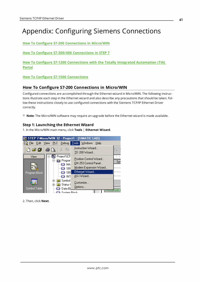
Siemens TCP/IP Ethernet Driver
Appendix: Configuring Siemens ConnectionsHow To Configure S7-200 Connections in Micro/WIN
How To Configure S7-300/400 Connections in STEP 7
How To Configure S7-1200 Connections with the Totally Integrated Automation (TIA)Portal
How To Configure S7-1500 Connections
How To Configure S7-200 Connections in Micro/WINConfigured connections are accomplished through the Ethernet wizard in Micro/WIN. The following instruc-tions illustrate each step in the Ethernet wizard and also describe any precautions that should be taken. Fol-low these instructions closely to use configured connections with the Siemens TCP/IP Ethernet Drivercorrectly.
Note: The Micro/WIN software may require an upgrade before the Ethernet wizard is made available.
Step 1: Launching the Ethernet Wizard1. In the Micro/WIN main menu, click Tools | Ethernet Wizard.
2. Then, clickNext.
www.ptc.com
61
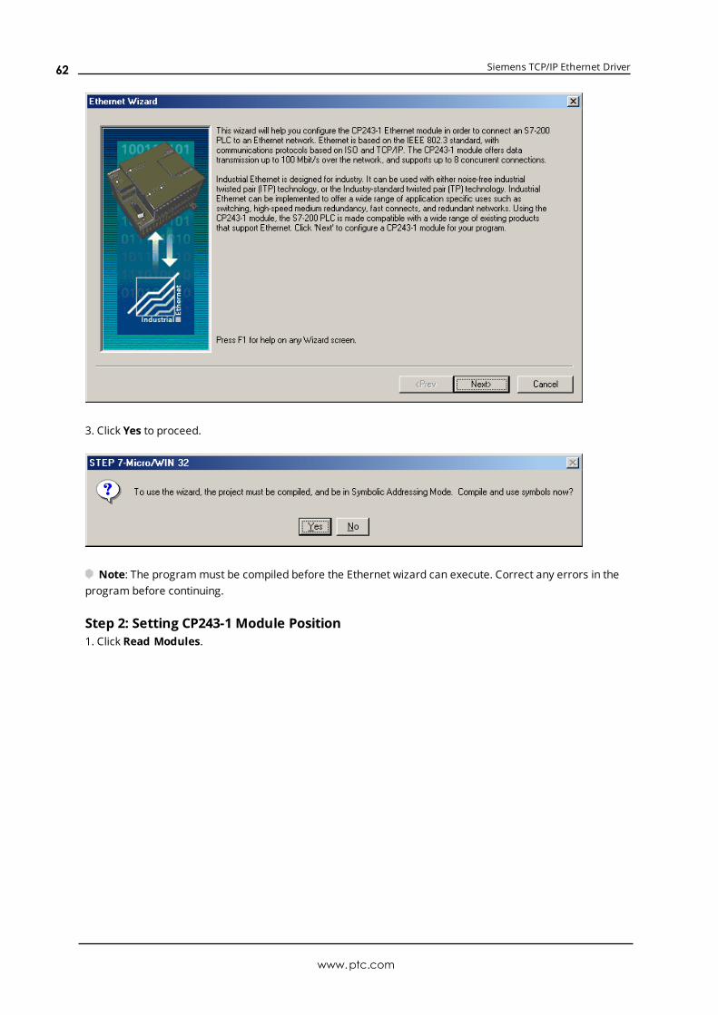
Siemens TCP/IP Ethernet Driver
3. Click Yes to proceed.
Note: The programmust be compiled before the Ethernet wizard can execute. Correct any errors in theprogram before continuing.
Step 2: Setting CP243-1 Module Position1. Click Read Modules.
www.ptc.com
62
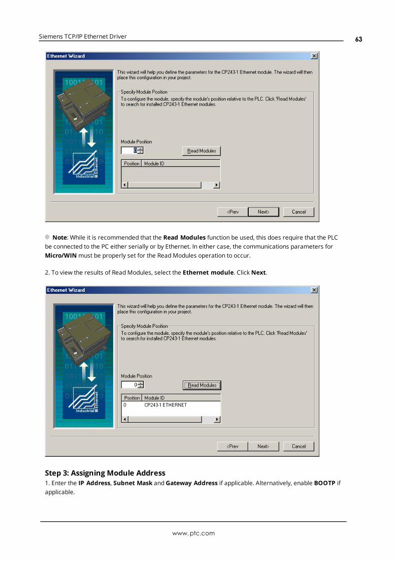
Siemens TCP/IP Ethernet Driver
Note: While it is recommended that the Read Modules function be used, this does require that the PLCbe connected to the PC either serially or by Ethernet. In either case, the communications parameters forMicro/WINmust be properly set for the ReadModules operation to occur.
2. To view the results of ReadModules, select the Ethernet module. ClickNext.
Step 3: Assigning Module Address1. Enter the IP Address, Subnet Mask and Gateway Address if applicable. Alternatively, enable BOOTP ifapplicable.
www.ptc.com
63
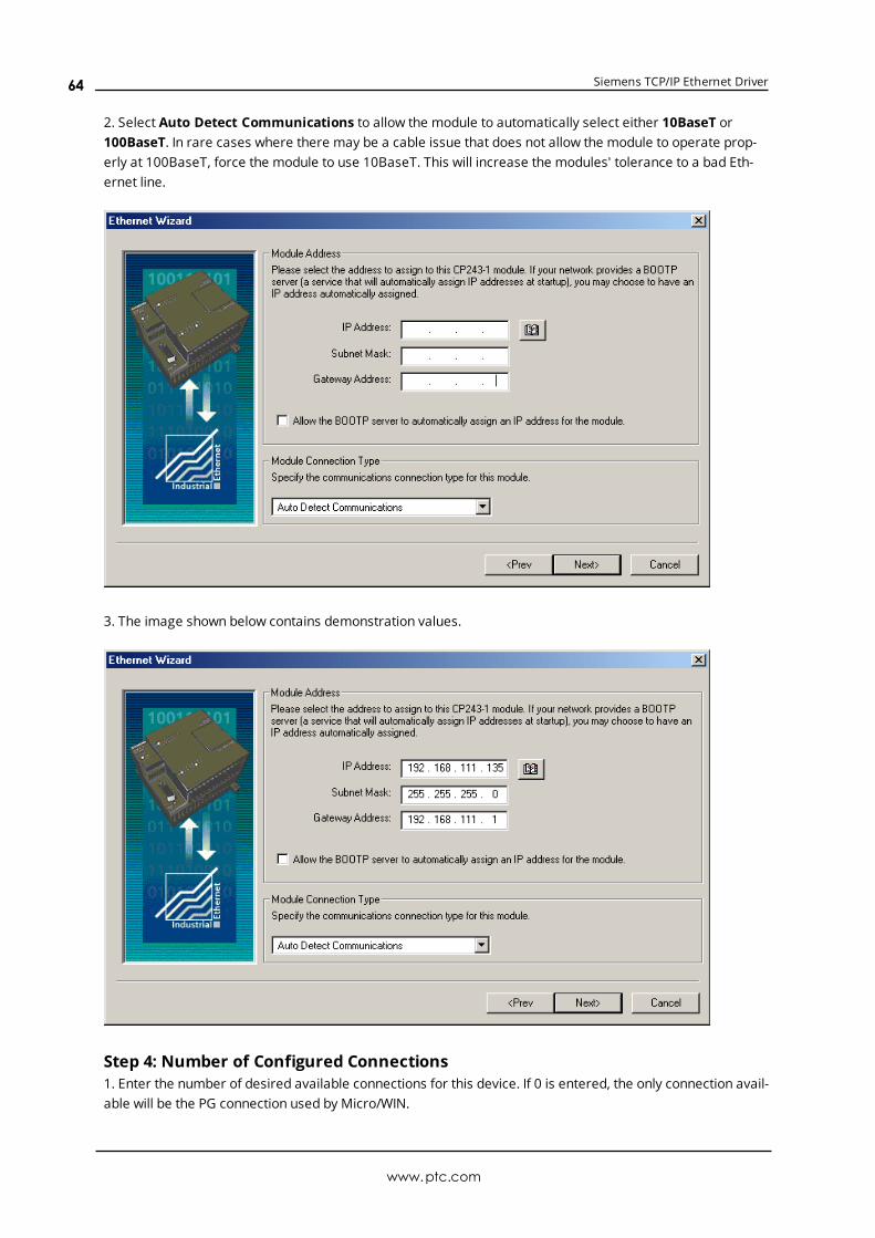
Siemens TCP/IP Ethernet Driver
2. Select Auto Detect Communications to allow the module to automatically select either 10BaseT or100BaseT. In rare cases where there may be a cable issue that does not allow the module to operate prop-erly at 100BaseT, force the module to use 10BaseT. This will increase the modules' tolerance to a bad Eth-ernet line.
3. The image shown below contains demonstration values.
Step 4: Number of Configured Connections1. Enter the number of desired available connections for this device. If 0 is entered, the only connection avail-able will be the PG connection used by Micro/WIN.
www.ptc.com
64
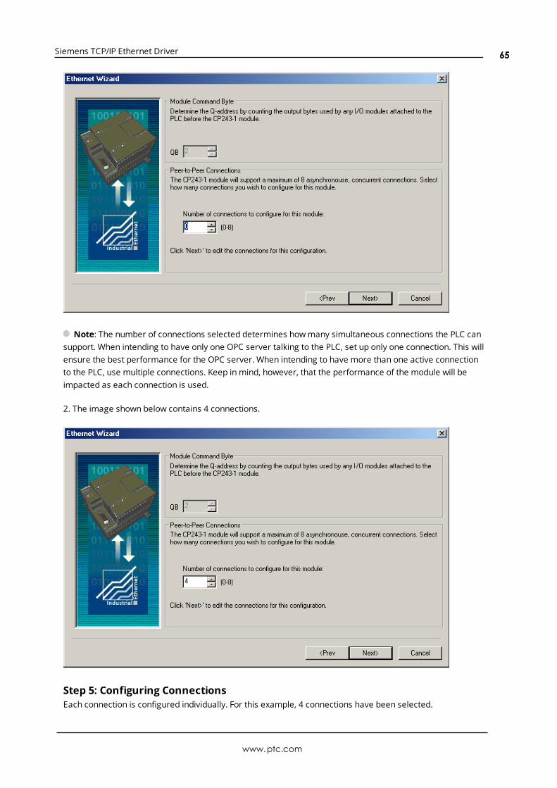
Siemens TCP/IP Ethernet Driver
Note: The number of connections selected determines howmany simultaneous connections the PLC cansupport. When intending to have only one OPC server talking to the PLC, set up only one connection. This willensure the best performance for the OPC server. When intending to have more than one active connectionto the PLC, use multiple connections. Keep in mind, however, that the performance of the module will beimpacted as each connection is used.
2. The image shown below contains 4 connections.
Step 5: Configuring ConnectionsEach connection is configured individually. For this example, 4 connections have been selected.
www.ptc.com
65
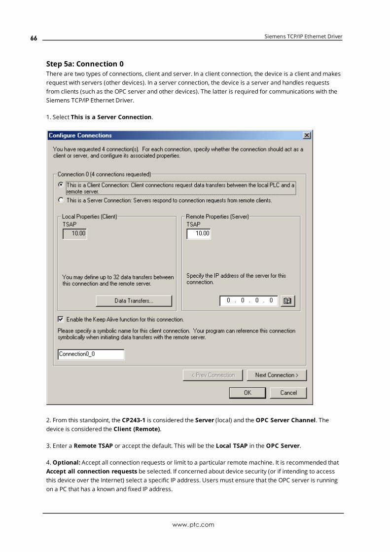
Siemens TCP/IP Ethernet Driver
Step 5a: Connection 0There are two types of connections, client and server. In a client connection, the device is a client andmakesrequest with servers (other devices). In a server connection, the device is a server and handles requestsfrom clients (such as the OPC server and other devices). The latter is required for communications with theSiemens TCP/IP Ethernet Driver.
1. Select This is a Server Connection.
2. From this standpoint, the CP243-1 is considered the Server (local) and the OPC Server Channel. Thedevice is considered the Client (Remote).
3. Enter a Remote TSAP or accept the default. This will be the Local TSAP in the OPC Server.
4.Optional: Accept all connection requests or limit to a particular remote machine. It is recommended thatAccept all connection requests be selected. If concerned about device security (or if intending to accessthis device over the Internet) select a specific IP address. Users must ensure that the OPC server is runningon a PC that has a known and fixed IP address.
www.ptc.com
66
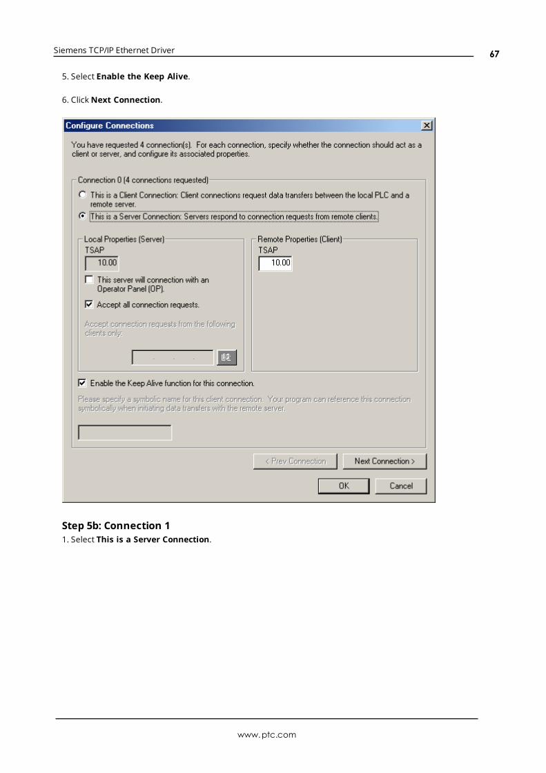
Siemens TCP/IP Ethernet Driver
5. Select Enable the Keep Alive.
6. ClickNext Connection.
Step 5b: Connection 11. Select This is a Server Connection.
www.ptc.com
67
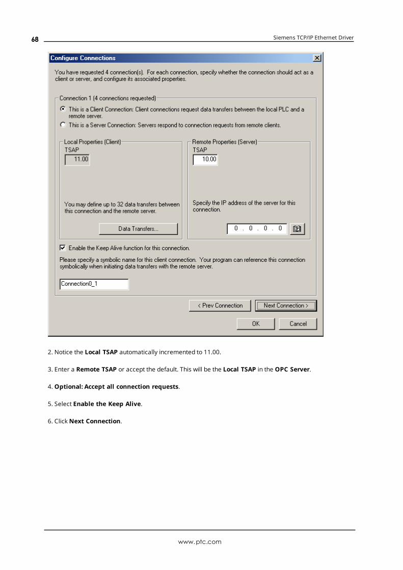
Siemens TCP/IP Ethernet Driver
2. Notice the Local TSAP automatically incremented to 11.00.
3. Enter a Remote TSAP or accept the default. This will be the Local TSAP in the OPC Server.
4.Optional: Accept all connection requests.
5. Select Enable the Keep Alive.
6. ClickNext Connection.
www.ptc.com
68
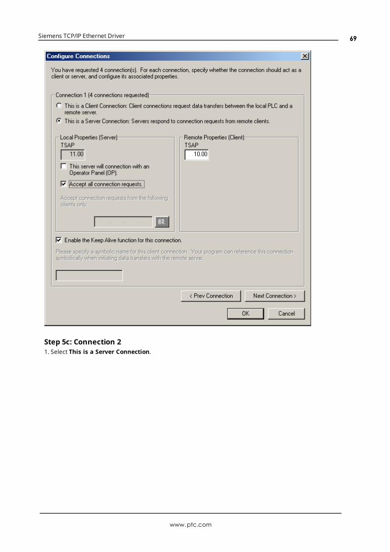
Siemens TCP/IP Ethernet Driver
Step 5c: Connection 21. Select This is a Server Connection.
www.ptc.com
69

Siemens TCP/IP Ethernet Driver
2. Notice the Local TSAP automatically incremented to 12.00.
3. Enter a Remote TSAP or accept the default. This will be the Local TSAP in the OPC Server.
4.Optional: Accept all connection requests.
5. Select Enable the Keep Alive.
6. ClickNext Connection.
www.ptc.com
70

Siemens TCP/IP Ethernet Driver
Step 5d: Connection 31. Select This is a Server Connection....
www.ptc.com
71

Siemens TCP/IP Ethernet Driver
2. Notice the Local TSAP automatically incremented to 13.00.
3. Enter a Remote TSAP or accept the default. This will be the Local TSAP in the OPC server.
4.Optional: Accept all connection requests.
5. Select Enable the Keep Alive.
6. ClickNext Connection.
www.ptc.com
72
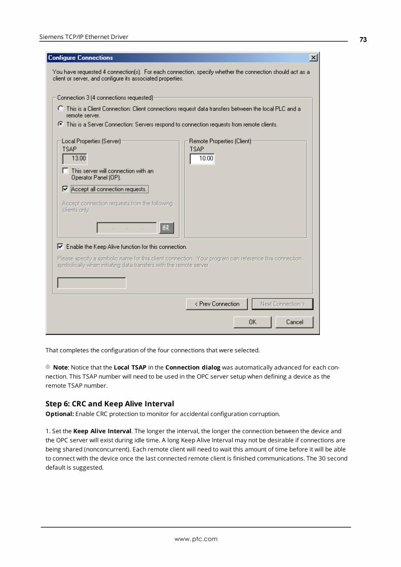
Siemens TCP/IP Ethernet Driver
That completes the configuration of the four connections that were selected.
Note: Notice that the Local TSAP in the Connection dialog was automatically advanced for each con-nection. This TSAP number will need to be used in the OPC server setup when defining a device as theremote TSAP number.
Step 6: CRC and Keep Alive IntervalOptional: Enable CRC protection to monitor for accidental configuration corruption.
1. Set the Keep Alive Interval. The longer the interval, the longer the connection between the device andthe OPC server will exist during idle time. A long Keep Alive Interval may not be desirable if connections arebeing shared (nonconcurrent). Each remote client will need to wait this amount of time before it will be ableto connect with the device once the last connected remote client is finished communications. The 30 seconddefault is suggested.
www.ptc.com
73

Siemens TCP/IP Ethernet Driver
Step 7: Memory for Configuration1. Click Suggest Address to let the wizard find the best available location to store the Ethernet con-figuration.
2. The image shown below displays the results.
www.ptc.com
74
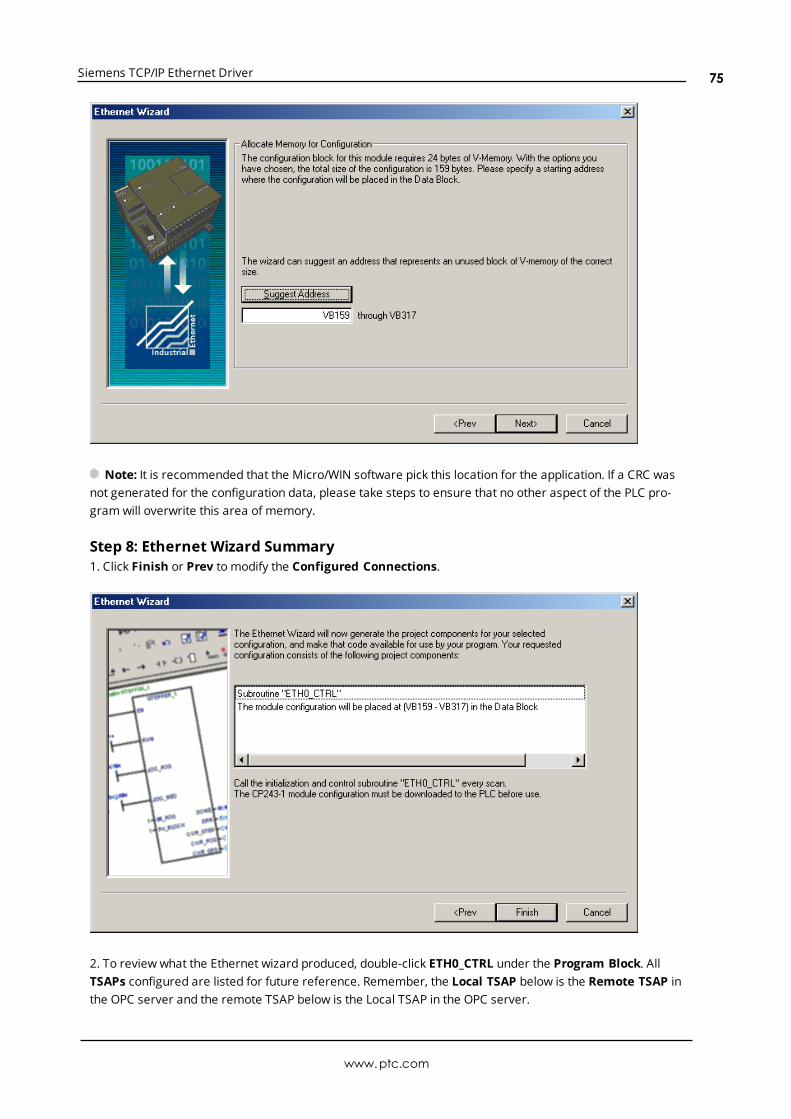
Siemens TCP/IP Ethernet Driver
Note: It is recommended that the Micro/WIN software pick this location for the application. If a CRC wasnot generated for the configuration data, please take steps to ensure that no other aspect of the PLC pro-gram will overwrite this area of memory.
Step 8: Ethernet Wizard Summary1. Click Finish or Prev to modify the Configured Connections.
2. To review what the Ethernet wizard produced, double-click ETH0_CTRL under the Program Block. AllTSAPs configured are listed for future reference. Remember, the Local TSAP below is the Remote TSAP inthe OPC server and the remote TSAP below is the Local TSAP in the OPC server.
www.ptc.com
75

Siemens TCP/IP Ethernet Driver
3. The image below shows ETH0_CTRL.
4. The image below shows ETH0_CFG.
5. Now that the results of the Ethernet wizard have been confirmed, a connection can be made using theOPC server.
How To Configure S7-300/400 Connections in STEP 7To configure the S7-300/400 for communications with the Siemens TCP/IP Ethernet Driver, both the CPU andthe Ethernet module will need to be configured as well. To do so, follow the directions below.
1. From the Simatic Manager, launchHW Config by double-clicking Hardware under the SIMATIC Station.
www.ptc.com
76
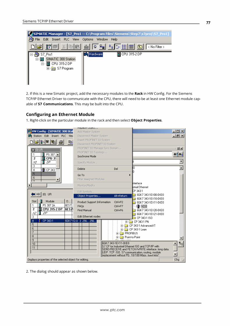
Siemens TCP/IP Ethernet Driver
2. If this is a new Simatic project, add the necessary modules to the Rack in HW Config. For the SiemensTCP/IP Ethernet Driver to communicate with the CPU, there will need to be at least one Ethernet module cap-able of S7 Communications. This may be built into the CPU.
Configuring an Ethernet Module1. Right-click on the particular module in the rack and then selectObject Properties.
2. The dialog should appear as shown below.
www.ptc.com
77
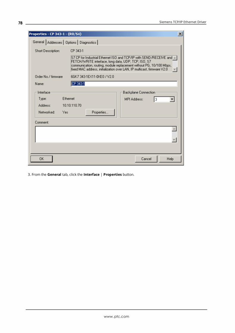
Siemens TCP/IP Ethernet Driver
3. From the General tab, click the Interface | Properties button.
www.ptc.com
78
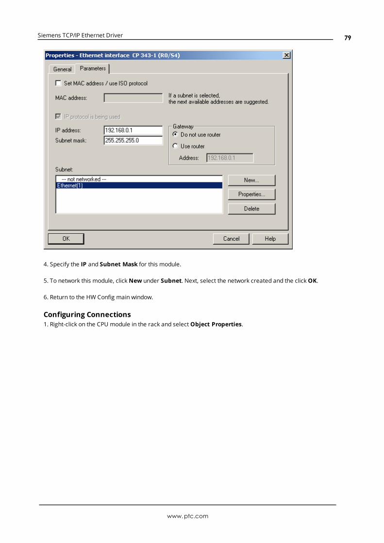
Siemens TCP/IP Ethernet Driver
4. Specify the IP and Subnet Mask for this module.
5. To network this module, clickNew under Subnet. Next, select the network created and the clickOK.
6. Return to the HW Config main window.
Configuring Connections1. Right-click on the CPU module in the rack and selectObject Properties.
www.ptc.com
79
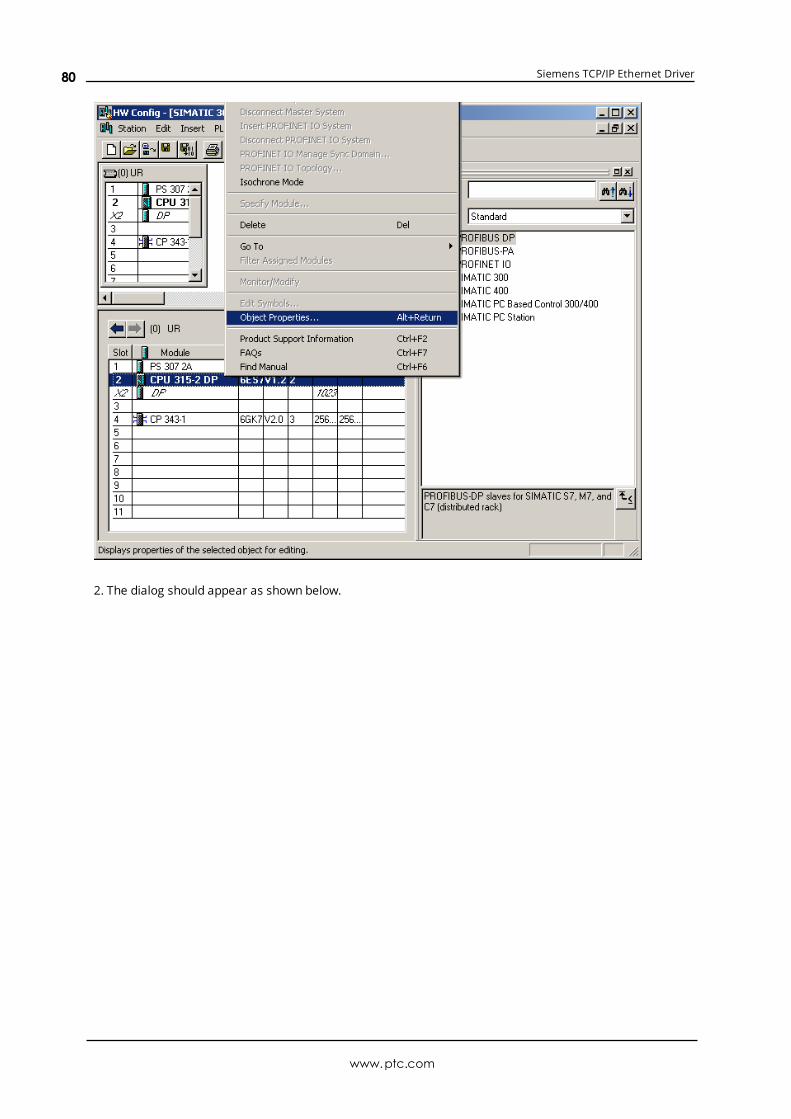
Siemens TCP/IP Ethernet Driver
2. The dialog should appear as shown below.
www.ptc.com
80
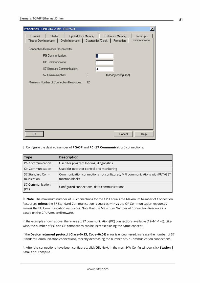
Siemens TCP/IP Ethernet Driver
3. Configure the desired number of PG/OP and PC (S7 Communication) connections.
Type Description
PG Communication Used for program loading, diagnostics
OP Communication Used for operator control andmonitoring
S7 Standard Com-munication
Communication connections not configured, MPI communications with PUT/GETfunction blocks
S7 Communication(PC)
Configured connections, data communications
Note: The maximum number of PC connections for the CPU equals the Maximum Number of ConnectionResourcesminus the S7 Standard Communication resourcesminus the OP Communication resourcesminus the PG Communication resources. Note that the Maximum Number of Connection Resources isbased on the CPU/version/firmware.
In the example shown above, there are six S7 communication (PC) connections available (12-4-1-1=6). Like-wise, the number of PG and OP connections can be increased using the same concept.
If the Device returned protocol [Class=0x83, Code=0x04] error is encountered, increase the number of S7Standard Communication connections, thereby decreasing the number of S7 Communication connections.
4. After the connections have been configured, clickOK. Next, in the main HW Config window click Station |Save and Compile.
www.ptc.com
81
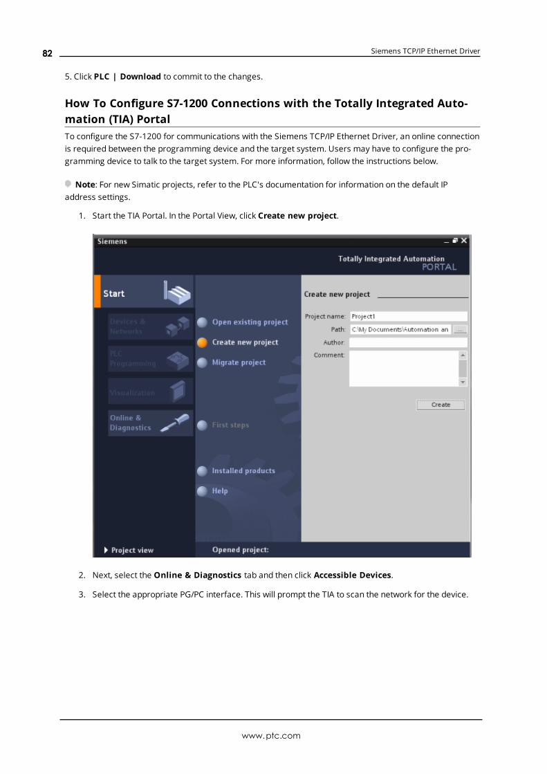
Siemens TCP/IP Ethernet Driver
5. Click PLC | Download to commit to the changes.
How To Configure S7-1200 Connections with the Totally Integrated Auto-mation (TIA) PortalTo configure the S7-1200 for communications with the Siemens TCP/IP Ethernet Driver, an online connectionis required between the programming device and the target system. Users may have to configure the pro-gramming device to talk to the target system. For more information, follow the instructions below.
Note: For new Simatic projects, refer to the PLC's documentation for information on the default IPaddress settings.
1. Start the TIA Portal. In the Portal View, click Create new project.
2. Next, select the Online & Diagnostics tab and then click Accessible Devices.
3. Select the appropriate PG/PC interface. This will prompt the TIA to scan the network for the device.
www.ptc.com
82
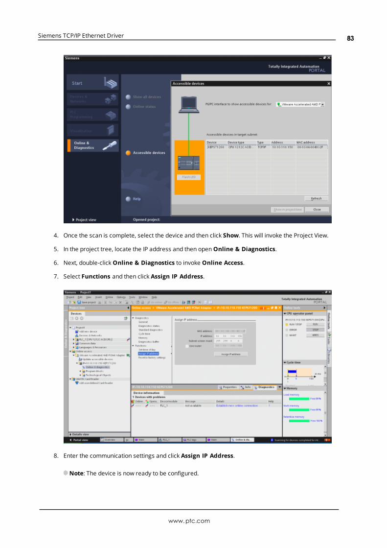
Siemens TCP/IP Ethernet Driver
4. Once the scan is complete, select the device and then click Show. This will invoke the Project View.
5. In the project tree, locate the IP address and then openOnline & Diagnostics.
6. Next, double-clickOnline & Diagnostics to invoke Online Access.
7. Select Functions and then click Assign IP Address.
8. Enter the communication settings and click Assign IP Address.
Note: The device is now ready to be configured.
www.ptc.com
83

Siemens TCP/IP Ethernet Driver
9. Return to the Portal View and then select the Device & Networks tab. Then, click Add new device.
10. Next, select the device's configuration and then click Add device. This will invoke the Project View,where the device's hardware can be further configured.
11. Once finished, view the project tree. Locate Program Blocks and PLC Tags and then configure theaddresses that will be used in the PLC project.
www.ptc.com
84

Siemens TCP/IP Ethernet Driver
Note: The device is now configured and can be placed in RunMode for communications.
How To Configure S7-1500 ConnectionsThe S7-1500 controller has an embedded Ethernet port that supports S7 communications over the Ethernetprotocol. It must be configured to allow access from the server, however. For more information, refer to theinstructions below.
1. To start, open the PLC project in the S7 TIA Portal software.
2. Next, open PLC Properties.
3. In the General tab, select Protection. Then, ensure that Full access (no protection) is enabled.
Note: At this time, the Siemens TCP/IP Ethernet Driver does not support the use of a password.
4. Next, check Permit access with PUT/GET communication from remote partner. Then, save thesettings.
www.ptc.com
85

Siemens TCP/IP Ethernet Driver
5. In the server, create a new channel. InDevice Driver, select Siemens TCP/IP Ethernet Driver fromthe drop-down list. Continue through the channel wizard, specifying channel properties as needed.Then, click Finish.
6. Next, create a new device. InModel, select S7-1500 from the Device Model drop-down list. Continuethrough the device wizard, specifying device properties as needed. Then, click Finish.
Note: The controller Protection settings are directly related to the device returning protocol error [Class-s=0x81, Code=0x04]. If this error occurs, the controller's memory (such as the Simatic memory card) mayneed to be reset. Once the controller's memory is reset, downloading the S7 project to the controller shouldnot prompt for a password.
www.ptc.com
86
Siemens TCP/IP Ethernet Driver
Appendix: Alternate Syntax SupportLimited addressing support is available for the following applications.
Applicom Direct-Link Item SyntaxINAT OPC-Server TCPIPH1 Item SyntaxSiemens Simatic Net Item SyntaxSofting S7/S5 OPC Server Item Syntax
Note: All brand and product names are trademarks, registered trademarks, or service marks of theirrespective holders.
Note: The offset for an atomic type tag in a data block is denoted by the column "Address" in Step 7, asshown above. This offset is denoted by the column "Offset" in the Siemens TIA Portal programming envir-onment.
Applicom Direct-Link Item SyntaxThe following support for the Applicom Direct-Link OPC server is considered to be limited. Care must betaken because the data type for a given S7 data type/suffix may differ from the data type for the same S7data type/suffix in the specified product. Applicom ASCII strings are not supported by this driver. The fol-lowing information is intended to be a guideline for users that are already familiar with and/or prefer the syn-tax of the specified product. For preferred item syntax, refer to Standard S7-300/400/1200/1500 ItemSyntax.
Address SyntaxInput, Output, Peripheral, Flag Memory Types<memory type><S7 data type><address>[<Data Type suffix>] [<Byte Switching suffix>]<memory type><S7 data type><address>[<Data Type suffix>]<_row_col>
Timer and Counter Memory Types<memory type><address>
DB Memory TypeDB<num>.<S7 data type><address>[<Data Type suffix>][< Byte Switching suffix>]DB<num>.<S7 data type><address>[<Data Type suffix>]<_row_col>where <num> ranges from 1 to 65535.
See Also: Examples
Memory TypesMemory Type Description Address Range Data Type Access
IE
Inputs
Dependent on S7 Data Type
Read/Write
QA
Outputs Read/Write
PIPE
Peripheral Inputs Read Only
PQPA
Peripheral Outputs Read/Write
www.ptc.com
87
Siemens TCP/IP Ethernet Driver
Memory Type Description Address Range Data Type Access
MF
Flag Memory Read/Write
DB Data Blocks Read/Write
T Timers T0-T65535 DWord, Long Read/Write
CZ
CountersC0-C65535Z0-Z65535
Word, Short Read/Write
See Also: Examples
S7 Data TypesThe S7 data type is used to coerce the data type for a tag. It does not apply to Timers and Counters. Thedefault data types are shown in bold. Suffixes are not required.
DataType
Description Address Range Data Type SuffixData Type w/Suffix
None*DBX**
Bit
0.b-65534.bDBX0.b-DBX65534.b
.b is Bit Number 0-15
Boolean
BDBB**
UnsignedByte
B0-B65535DBB0-DBB65535
Byte, Char
WDBW**
UnsignedWord
W0-W65534DBW0-DBW65534
Word, Short, BCD
DDBD**
UnsignedDouble Word
D0-D65532DBD0-DBD65532
DWord, Long, LBCD,Float
F Float
*No S7 data type specified. Applies to non-DB memory types only.**Applies to DB memory types only.
See Also: Examples
Data Type SuffixesSuffix Description Data Type
F 32-bit IEEE floating point value Float
Byte Switching SuffixesThese suffixes are used to switch the bytes that compose data of type 16-bit Word, 32-bit DWord, or 32-bitFloat. The switching is applied after the device-level addressing option for byte Order is applied. For moreinformation, refer to Addressing Options.
Byte Switching Suffixes can be used with all memory types except Timers and Counters (T, C, and Z) and Peri-pheral Inputs and Outputs (PI, PE, PQ, and PA). For information on the various types of switching that dependon the suffix and data type of the item, refer to the table below.
www.ptc.com
88
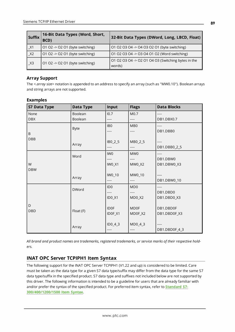
Siemens TCP/IP Ethernet Driver
Suffix16-Bit Data Types (Word, Short,BCD)
32-Bit Data Types (DWord, Long, LBCD, Float)
_X1 O1 O2 -> O2 O1 (byte switching) O1 O2 O3 O4 -> O4 O3 O2 O1 (byte switching)
_X2 O1 O2 -> O2 O1 (byte switching) O1 O2 O3 O4 -> O3 O4 O1 O2 (Word switching)
_X3 O1 O2 -> O2 O1 (byte switching)O1 O2 O3 O4 -> O2 O1 O4 O3 (Switching bytes in thewords)
Array SupportThe <.array size> notation is appended to an address to specify an array (such as "MW0.10"). Boolean arraysand string arrays are not supported.
ExamplesS7 Data Type Data Type Input Flags Data Blocks
NoneDBX
BooleanBoolean
I0.7----
M0.7----
----DB1.DBX0.7
BDBB
Byte
Array
IB0----
IB0_2_5----
MB0----
MB0_2_5----
----DB1.DBB0
----DB1.DBB0_2_5
WDBW
Word
Array
IW0----IW0_X1
IW0_10----
MW0----MW0_X2
MW0_10----
----DB1.DBW0DB1.DBW0_X3
----DB1.DBW0_10
DDBD
DWord
Float (F)
Array
ID0----ID0_X1
ID0FID0F_X1
ID0_4_3----
MD0----MD0_X2
MD0FMD0F_X2
MD0_4_3----
----DB1.DBD0DB1.DBD0_X3
DB1.DBD0FDB1.DBD0F_X3
----DB1.DBD0F_4_3
All brand and product names are trademarks, registered trademarks, or service marks of their respective hold-ers.
INAT OPC Server TCPIPH1 Item SyntaxThe following support for the INAT OPC Server TCPIPH1 (V1.22 and up) is considered to be limited. Caremust be taken as the data type for a given S7 data type/suffix may differ from the data type for the same S7data type/suffix in the specified product. S7 data type and suffixes not included below are not supported bythis driver. The following information is intended to be a guideline for users that are already familiar withand/or prefer the syntax of the specified product. For preferred item syntax, refer to Standard S7-300/400/1200/1500 Item Syntax.
www.ptc.com
89
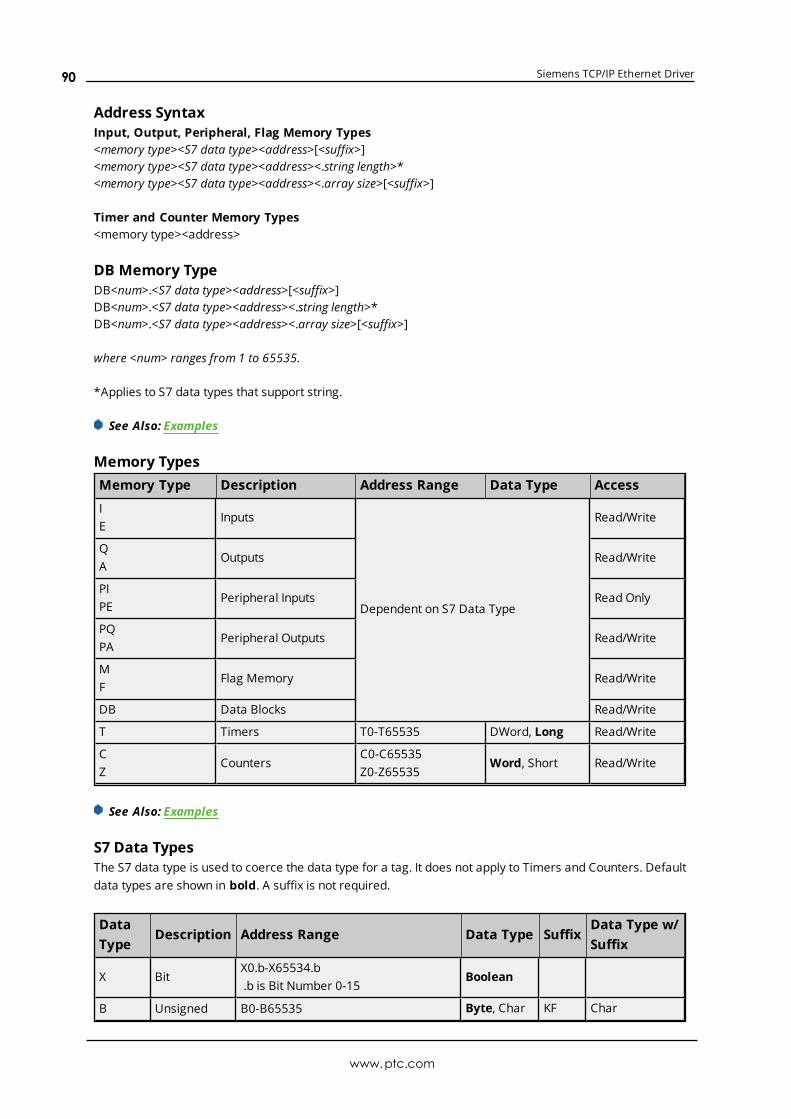
Siemens TCP/IP Ethernet Driver
Address SyntaxInput, Output, Peripheral, Flag Memory Types<memory type><S7 data type><address>[<suffix>]<memory type><S7 data type><address><.string length>*<memory type><S7 data type><address><.array size>[<suffix>]
Timer and Counter Memory Types<memory type><address>
DB Memory TypeDB<num>.<S7 data type><address>[<suffix>]DB<num>.<S7 data type><address><.string length>*DB<num>.<S7 data type><address><.array size>[<suffix>]
where <num> ranges from 1 to 65535.
*Applies to S7 data types that support string.
See Also: Examples
Memory TypesMemory Type Description Address Range Data Type Access
IE
Inputs
Dependent on S7 Data Type
Read/Write
QA
Outputs Read/Write
PIPE
Peripheral Inputs Read Only
PQPA
Peripheral Outputs Read/Write
MF
Flag Memory Read/Write
DB Data Blocks Read/Write
T Timers T0-T65535 DWord, Long Read/Write
CZ
CountersC0-C65535Z0-Z65535
Word, Short Read/Write
See Also: Examples
S7 Data TypesThe S7 data type is used to coerce the data type for a tag. It does not apply to Timers and Counters. Defaultdata types are shown in bold. A suffix is not required.
DataType
Description Address Range Data Type SuffixData Type w/Suffix
X BitX0.b-X65534.b.b is Bit Number 0-15
Boolean
B Unsigned B0-B65535 Byte, Char KF Char
www.ptc.com
90

Siemens TCP/IP Ethernet Driver
DataType
Description Address Range Data Type SuffixData Type w/Suffix
Byte Byte BYTE0-BYTE65535
WWord
UnsignedWord
W0-W65534WORD0-WORD65534
Word,Short, BCD
BCDKF
BCDShort
IINT
SignedWordI0-I65534INT0-INT65534
Word,Short, BCD
BCD BCD
DDWORD
UnsignedDouble Word
D0-D65532DWORD0-DWORD65532
DWord,Long,LBCD, Float
BCDIEEEKF
LBCDFloatLong
DIDINT
SignedDouble Word
DI0-DI65532DINT0-DINT65532
DWord,Long,LBCD, Float
BCDIEEE
LBCDFloat
RREAL
IEEE FloatR0-R65532REAL0-REAL65532
Float
GString
S7 String
G0.n-G65532.nSTRING0.n-STRING65532.n.n is string length0<n<= 254 (PDU size of 480 andabove)0<n<= 210 (PDU size below 480)0<n<= 254 (Netlink S7300 and NetlinkS7400 Models)
String
See Also: Examples
SuffixesSuffix Description Data Type
BCD
Two byte packed BCD for Word referencesValue range is 0-9999
Four byte packed BCD for DWord referencesValue range is 0-99999999
BCD
LBCD
IEEE 32-bit IEEE floating point value Float
KF SignedCharShortLong
Array SupportThe <.array size> notation is appended to an address to specify an array (such as MW0.10). Boolean arraysand string arrays are not supported.
ExamplesS7 Data Type Data Type Input Flags Data Blocks
X Boolean IX0.7 MX0.7 DB1.X0.7
B Byte IB0 MB0 DB1.B0
www.ptc.com
91

Siemens TCP/IP Ethernet Driver
S7 Data Type Data Type Input Flags Data Blocks
ByteChar (KF)
Array
IBYTE0
IB0KFIBYTE0KF
IB0KF.10IBYTE0KF.10
MBYTE0
MB0KFMBYTE0KF
MB0KF.10MBYTE0KF.10
DB1.BYTE0
DB1.B0KFDB1.BYTE0KF
DB1.B0KF.10DB1.BYTE0KF.10
WWord
Word
BCD (BCD)
Short (KF)
Array
IW0IWORD0
IW0BCDIWORD0BCD
IW0KFIWORD0KF
IW0BCD.10IWORD0BCD.10
MW0MWORD0
MW0BCDMWORD0BCD
MW0KFMWORD0KF
MW0BCD.10MWORD0BCD.10
DB1.W0DB1.WORD0
DB1.W0BCDDB1.WORD0BCD
DB1.W0KFDB1.WORD0KF
DB1.W0BCD.10DB1.WORD0BCD.10
IINT
Short
BCD (BCD)
Array
II0IINT0
II0BCDIINT0BCD
II0.10IINT0.10
MI0MINT0
MI0BCDMINT0BCD
MI0.10MINT0.10
DB1.I0DB1.INT0
DB1.I0BCDDB1.INT0BCD
DB1.I0.10DB1.INT0.10
DDWORD
DWord
LBCD (BCD)
Float (IEEE)
Long (KF)
Array
ID0IDWORD0
ID0BCDIDWORD0BCD
ID0IEEEIDWORD0IEEE
ID0KFIDWORD0KF
ID0IEEE.10IDWORD0IEEE.10
MD0MDWORD0
MD0BCDMDWORD0BCD
MD0IEEEMDWORD0IEEE
MD0KFMDWORD0KF
MD0IEEE.10MDWORD0IEEE.10
DB1.D0DB1.DWORD0
DB1.D0BCDDB1.DWORD0BCD
DB1.D0IEEEDB1.DWORD0IEEE
DB1.D0KFDB1.DWORD0KF
DB1.D0IEEE.10DB1.DWORD0IEEE.10
DIDINT
Long
LBCD (BCD)
Float (IEEE)
IDI0IDINT0
IDI0BCDIDINT0BCD
IDI0IEEEIDINT0IEEE
MDI0MDINT0
MDI0BCDMDINT0BCD
MDI0IEEEMDINT0IEEE
DB1.DI0DB1.DINT0
DB1.DI0BCDDB1.DINT0BCD
DB1.DI0IEEEDB1.DINT0IEEE
www.ptc.com
92

Siemens TCP/IP Ethernet Driver
S7 Data Type Data Type Input Flags Data Blocks
ArrayIDI0BCD.10IDINT0BCD.10
MDI0BCD.10MDINT0BCD.10
DB1.DI0BCD.10DB1.DINT0BCD.10
RREAL
Float
Array
IR0IREAL0
IR0.10IREAL0.10
MR0MREAL0
MR0.10MREAL0.10
DB1.R0DB1.REAL0
DB1.R0.10DB1.REAL0.10
GString
StringIG0.10ISTRING0.10
MG0.10MSTRING0.10
DB1.G0.10DB1.STRING0.10
All brand and product names are trademarks, registered trademarks, or service marks of their respective hold-ers.
Siemens Simatic Net Item SyntaxThe following support for the Siemens Simatic Net OPC server is considered to be limited. Care must betaken as the data type for a given S7 data type may differ from the data type for the same S7 data type inthe specified product. S7 data types not included below are not supported by this driver. The followinginformation is intended to be a guideline for users that are already familiar with and/or prefer the syntax ofthe specified product. For preferred item syntax, refer to Standard S7-300/400/1200/1500 Item Syntax.
Address SyntaxInput, Output, Peripheral, Flag Memory Types<memory type><S7 data type><address><memory type><S7 data type><address><.string length><memory type><S7 data type><address><,array size>
Timer and Counter Memory Types<memory type><address>
DB Memory TypeDB<num>,<S7 data type><address>DB<num>,<S7 data type><address><.string length>*DB<num>,<S7 data type><address><,array size>
where <num> ranges from 1 to 65535.
*Applies to S7 data types that support String.
See Also: Examples
Memory TypesMemory Type Description Address Range Data Type Access
IE
Inputs
Dependent on S7 Data Type
Read/Write
QA
Outputs Read/Write
www.ptc.com
93
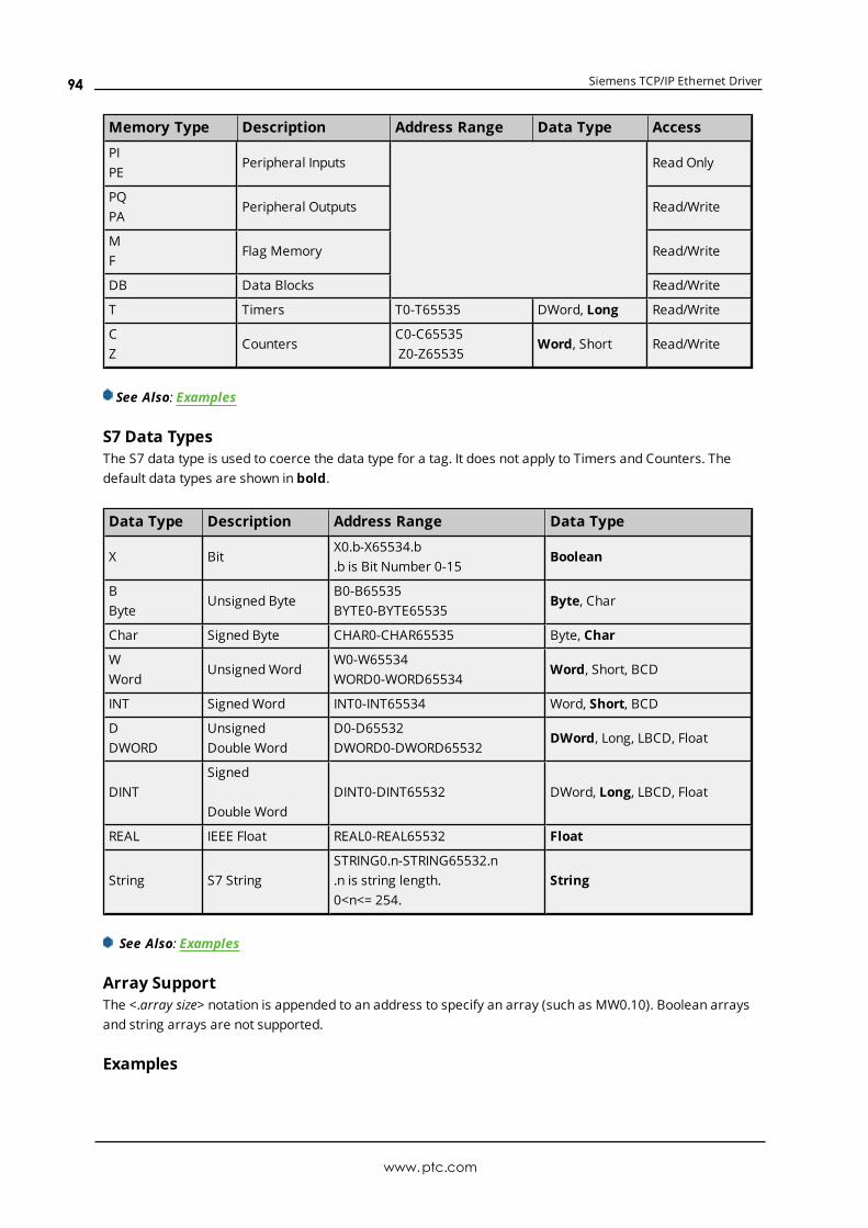
Siemens TCP/IP Ethernet Driver
Memory Type Description Address Range Data Type Access
PIPE
Peripheral Inputs Read Only
PQPA
Peripheral Outputs Read/Write
MF
Flag Memory Read/Write
DB Data Blocks Read/Write
T Timers T0-T65535 DWord, Long Read/Write
CZ
CountersC0-C65535Z0-Z65535
Word, Short Read/Write
See Also: Examples
S7 Data TypesThe S7 data type is used to coerce the data type for a tag. It does not apply to Timers and Counters. Thedefault data types are shown in bold.
Data Type Description Address Range Data Type
X BitX0.b-X65534.b.b is Bit Number 0-15
Boolean
BByte
Unsigned ByteB0-B65535BYTE0-BYTE65535
Byte, Char
Char Signed Byte CHAR0-CHAR65535 Byte, Char
WWord
UnsignedWordW0-W65534WORD0-WORD65534
Word, Short, BCD
INT SignedWord INT0-INT65534 Word, Short, BCD
DDWORD
UnsignedDouble Word
D0-D65532DWORD0-DWORD65532
DWord, Long, LBCD, Float
DINTSigned
Double WordDINT0-DINT65532 DWord, Long, LBCD, Float
REAL IEEE Float REAL0-REAL65532 Float
String S7 StringSTRING0.n-STRING65532.n.n is string length.0<n<= 254.
String
See Also: Examples
Array SupportThe <.array size> notation is appended to an address to specify an array (such as MW0.10). Boolean arraysand string arrays are not supported.
Examples
www.ptc.com
94

Siemens TCP/IP Ethernet Driver
S7 Data Type Data Type Input Flags Data Blocks
X Boolean IX0.7 MX0.7 DB1,X0.7
BByte
Byte
Array
IB0IBYTE0
IB0,10IBYTE0,10
MB0MBYTE0
MB0,10MBYTE0,10
DB1,B0DB1,BYTE0
DB1,B0,10DB1,BYTE0,10
CharChar
Array
ICHAR0
ICHAR0,10
MCHAR0
MCHAR0,10
DB1,CHAR0
DB1,CHAR0,10
WWord
Word
Array
IW0IWORD0
IW0,10IWORD0,10
MW0MWORD0
MW0,10MWORD0,10
DB1,W0DB1,WORD0
DB1,W0,10DB1,WORD0,10
INTShort
Array
IINT0
IINT0,10
MINT0
MINT0,10
DB1,INT0
DB1,INT0,10
DDWORD
DWord
Array
ID0IDWORD0
ID0,10IDWORD0,10
MD0MDWORD0
MD0,10MDWORD0,10
DB1,D0DB1,DWORD0
DB1,D0,10DB1,DWORD0,10
DINTLong
Array
IDINT0
IDINT0,10
MDINT0
MDINT0,10
DB1,DINT0
DB1,DINT0,10
REALFloat
Array
IREAL0
IREAL0,10
MREAL0
MREAL0,10
DB1,REAL0
DB1,REAL0,10
String String ISTRING0.10 MSTRING0.10 DB1,STRING0.10
All brand and product names are trademarks, registered trademarks, or service marks of their respective hold-ers.
Siemens STEP 7 Item SyntaxThe following support for Siemens STEP 7 Variable Table (VAT) syntax is considered to be limited. Care mustbe taken as the data type for a given S7 data type/suffix may differ from the data type for the same S7 datatype/suffix in the specified product. S7 data types not included below are not supported by this driver. The fol-lowing information is intended to be a guideline for users that are already familiar with and/or prefer the syn-tax of the specified product. For preferred item syntax, refer to Standard S7-300/400/1200/1500 ItemSyntax.
Address SyntaxInput, Output, Peripheral, Flag Memory Types<memory type><S7 data type><address>
Timer and Counter Memory Types<memory type><address>
www.ptc.com
95
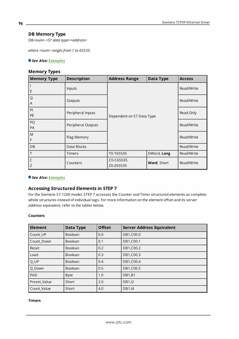
Siemens TCP/IP Ethernet Driver
DB Memory TypeDB<num>.<S7 data type><address>
where <num> ranges from 1 to 65535.
See Also: Examples
Memory TypesMemory Type Description Address Range Data Type Access
IE
Inputs
Dependent on S7 Data Type
Read/Write
QA
Outputs Read/Write
PIPE
Peripheral Inputs Read Only
PQPA
Peripheral Outputs Read/Write
MF
Flag Memory Read/Write
DB Data Blocks Read/Write
T Timers T0-T65535 DWord, Long Read/Write
CZ
CountersC0-C65535Z0-Z65535
Word, Short Read/Write
See Also: Examples
Accessing Structured Elements in STEP 7For the Siemens S7-1200 model, STEP 7 accesses the Counter and Timer structured elements as completewhole structures instead of individual tags. For more information on the element offset and its serveraddress equivalent, refer to the tables below.
Counters
Element Data Type Offset Server Address Equivalent
Count_UP Boolean 0.0 DB1,C00.0
Count_Down Boolean 0.1 DB1,C00.1
Reset Boolean 0.2 DB1,C00.2
Load Boolean 0.3 DB1,C00.3
Q_UP Boolean 0.4 DB1,C00.4
Q_Down Boolean 0.5 DB1,C00.5
PAD Byte 1.0 DB1,B1
Preset_Value Short 2.0 DB1,I2
Count_Value Short 4.0 DB1,I4
Timers
www.ptc.com
96

Siemens TCP/IP Ethernet Driver
Element Data Type Offset Server Address Equivalent
Start DWord 0.0 DB1,D0
Preset DWord 4.0 DB1,D4
Elapsed DWord 8.0 DB1,D8
Running Bool 12.0 DB1,DBX12.0
IN Bool 12.1 DB1,DBX12.1
Q Bool 12.2 DB1,DBX12.2
PAD Byte 13.0 DB1,DBB13
PAD_2 Byte 14.0 DB1,DBB14
PAD_3 Byte 15.0 DB1,DBB15
For more information, refer to Standard S7-300/400/1200/1500 Item Syntax.
S7 Data TypesThe S7 data type is used to coerce the data type for a tag. It does not apply to Counters and Timers. Thedefault data types are shown in bold.
DataType
Description Address Range Data Type SuffixData Type w/Suffix
None*DBX**
Bit
0.b-65534.bDBX0.b-DBX65534.b.b is Bit Number 0-15
Boolean
BDBB**
UnsignedByte
B0-B65535DBB0-DBB65535
Byte, Char
WDBW**
UnsignedWord
W0-W65534DBW0-DBW65534
Word, Short, BCD
DDBD**
UnsignedDouble Word
D0-D65532DBD0-DBD65532
DWord, Long, LBCD,Float
F Float
*No S7 data type specified. Applies to non-DB memory types only.**Applies to DB memory types only.
See Also: Examples
ExamplesS7 Data Type Data Type Input Flags Data Blocks
NoneDBX
BooleanI0.7----
M0.7----
----DB1.DBX0.7
BDBB
ByteIB0----
MB0----
----DB1.DBB0
WDBW
WordIW0----
MW0----
----DB1.DBW0
D DWord ID0 MD0 ----
www.ptc.com
97
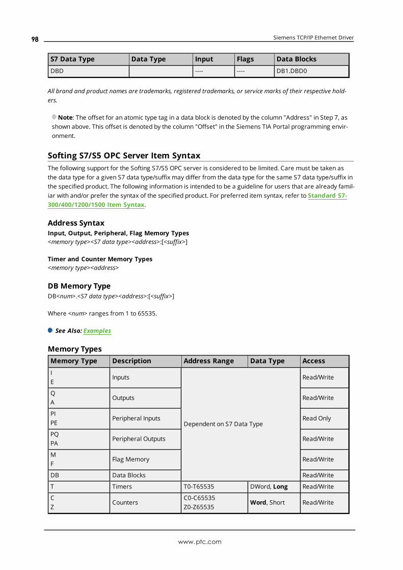
Siemens TCP/IP Ethernet Driver
S7 Data Type Data Type Input Flags Data Blocks
DBD ---- ---- DB1.DBD0
All brand and product names are trademarks, registered trademarks, or service marks of their respective hold-ers.
Note: The offset for an atomic type tag in a data block is denoted by the column "Address" in Step 7, asshown above. This offset is denoted by the column "Offset" in the Siemens TIA Portal programming envir-onment.
Softing S7/S5 OPC Server Item SyntaxThe following support for the Softing S7/S5 OPC server is considered to be limited. Care must be taken asthe data type for a given S7 data type/suffix may differ from the data type for the same S7 data type/suffix inthe specified product. The following information is intended to be a guideline for users that are already famil-iar with and/or prefer the syntax of the specified product. For preferred item syntax, refer to Standard S7-300/400/1200/1500 Item Syntax.
Address SyntaxInput, Output, Peripheral, Flag Memory Types<memory type><S7 data type><address>:[<suffix>]
Timer and Counter Memory Types<memory type><address>
DB Memory TypeDB<num>.<S7 data type><address>:[<suffix>]
Where <num> ranges from 1 to 65535.
See Also: Examples
Memory TypesMemory Type Description Address Range Data Type Access
IE
Inputs
Dependent on S7 Data Type
Read/Write
QA
Outputs Read/Write
PIPE
Peripheral Inputs Read Only
PQPA
Peripheral Outputs Read/Write
MF
Flag Memory Read/Write
DB Data Blocks Read/Write
T Timers T0-T65535 DWord, Long Read/Write
CZ
CountersC0-C65535Z0-Z65535
Word, Short Read/Write
www.ptc.com
98
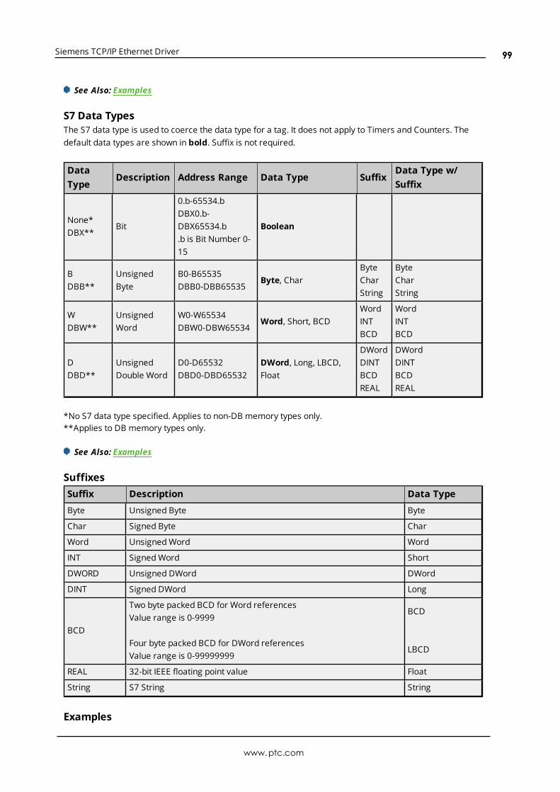
Siemens TCP/IP Ethernet Driver
See Also: Examples
S7 Data TypesThe S7 data type is used to coerce the data type for a tag. It does not apply to Timers and Counters. Thedefault data types are shown in bold. Suffix is not required.
DataType
Description Address Range Data Type SuffixData Type w/Suffix
None*DBX**
Bit
0.b-65534.bDBX0.b-DBX65534.b.b is Bit Number 0-15
Boolean
BDBB**
UnsignedByte
B0-B65535DBB0-DBB65535
Byte, CharByteCharString
ByteCharString
WDBW**
UnsignedWord
W0-W65534DBW0-DBW65534
Word, Short, BCDWordINTBCD
WordINTBCD
DDBD**
UnsignedDouble Word
D0-D65532DBD0-DBD65532
DWord, Long, LBCD,Float
DWordDINTBCDREAL
DWordDINTBCDREAL
*No S7 data type specified. Applies to non-DB memory types only.**Applies to DB memory types only.
See Also: Examples
SuffixesSuffix Description Data Type
Byte Unsigned Byte Byte
Char Signed Byte Char
Word UnsignedWord Word
INT SignedWord Short
DWORD Unsigned DWord DWord
DINT Signed DWord Long
BCD
Two byte packed BCD for Word referencesValue range is 0-9999
Four byte packed BCD for DWord referencesValue range is 0-99999999
BCD
LBCD
REAL 32-bit IEEE floating point value Float
String S7 String String
Examples
www.ptc.com
99
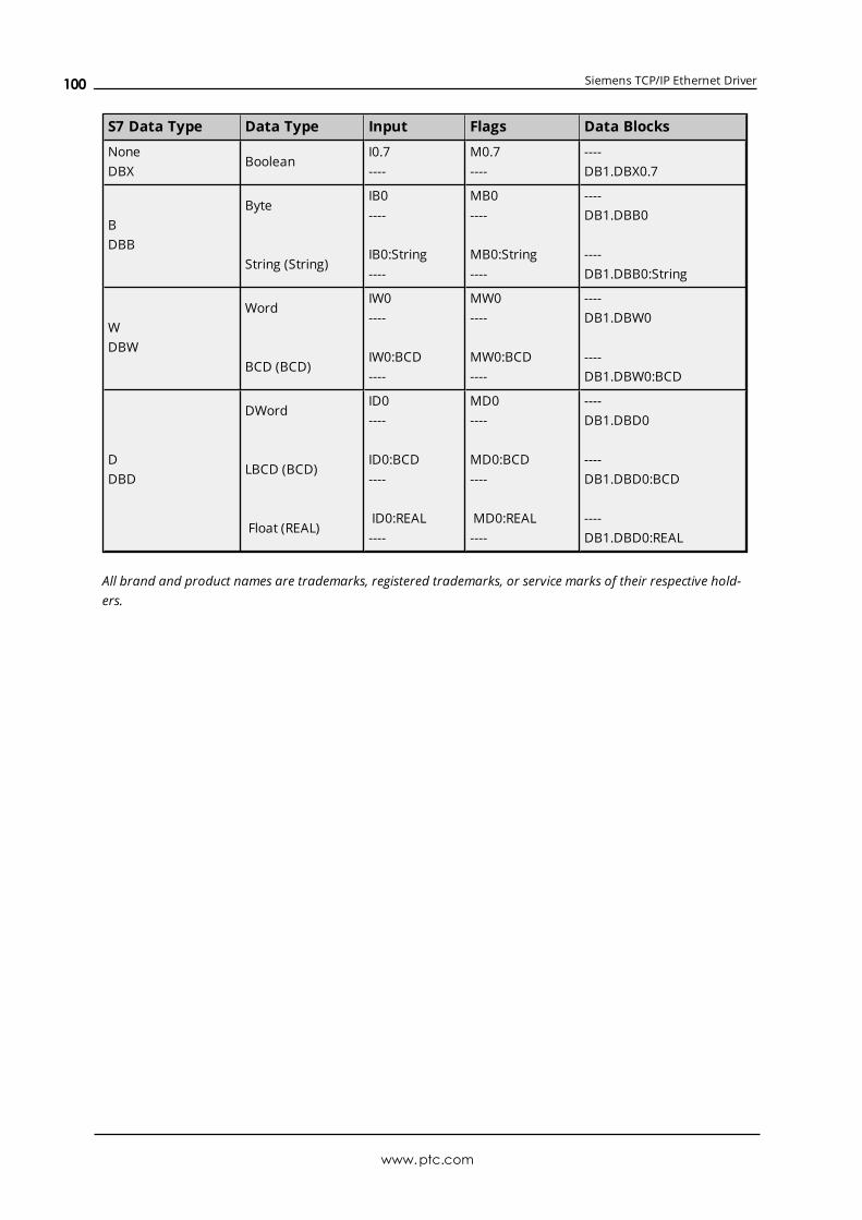
Siemens TCP/IP Ethernet Driver
S7 Data Type Data Type Input Flags Data Blocks
NoneDBX
BooleanI0.7----
M0.7----
----DB1.DBX0.7
BDBB
Byte
String (String)
IB0----
IB0:String----
MB0----
MB0:String----
----DB1.DBB0
----DB1.DBB0:String
WDBW
Word
BCD (BCD)
IW0----
IW0:BCD----
MW0----
MW0:BCD----
----DB1.DBW0
----DB1.DBW0:BCD
DDBD
DWord
LBCD (BCD)
Float (REAL)
ID0----
ID0:BCD----
ID0:REAL----
MD0----
MD0:BCD----
MD0:REAL----
----DB1.DBD0
----DB1.DBD0:BCD
----DB1.DBD0:REAL
All brand and product names are trademarks, registered trademarks, or service marks of their respective hold-ers.
www.ptc.com
100
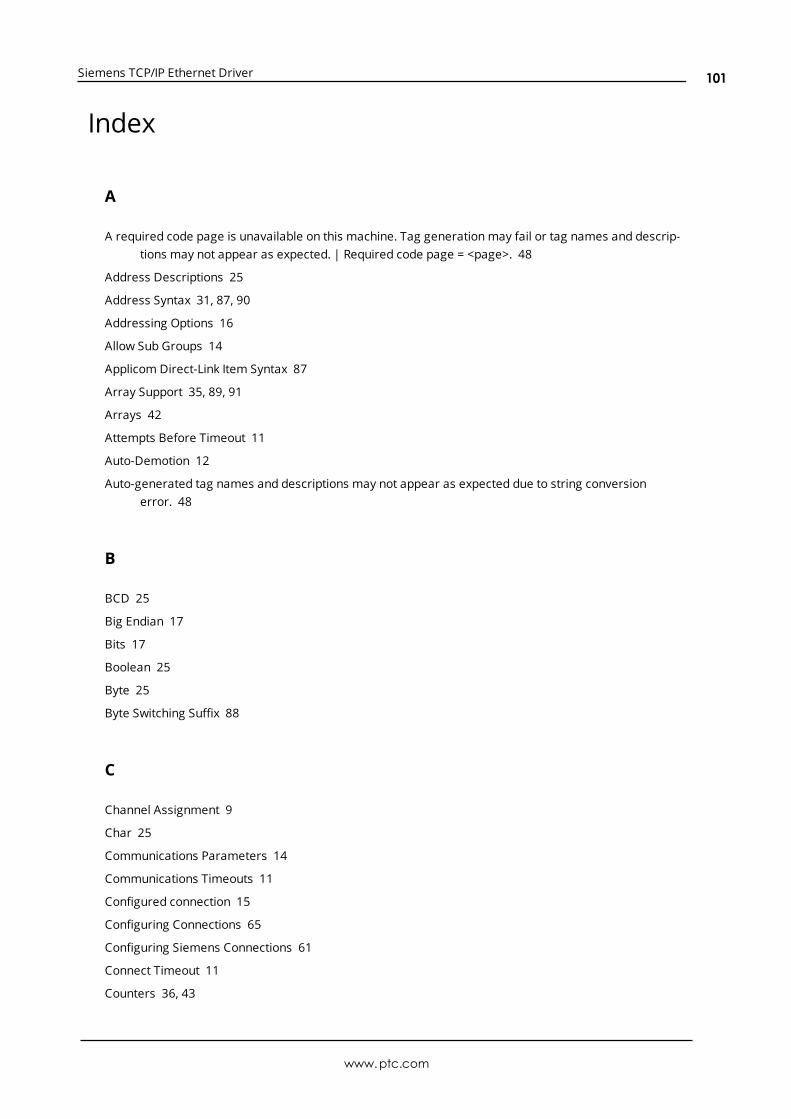
Siemens TCP/IP Ethernet Driver
Index
A
A required code page is unavailable on this machine. Tag generationmay fail or tag names and descrip-tions may not appear as expected. | Required code page = <page>. 48
Address Descriptions 25
Address Syntax 31, 87, 90
Addressing Options 16
Allow Sub Groups 14
Applicom Direct-Link Item Syntax 87
Array Support 35, 89, 91
Arrays 42
Attempts Before Timeout 11
Auto-Demotion 12
Auto-generated tag names and descriptions may not appear as expected due to string conversionerror. 48
B
BCD 25
Big Endian 17
Bits 17
Boolean 25
Byte 25
Byte Switching Suffix 88
C
Channel Assignment 9
Char 25
Communications Parameters 14
Communications Timeouts 11
Configured connection 15
Configuring Connections 65
Configuring Siemens Connections 61
Connect Timeout 11
Counters 36, 43
www.ptc.com
101
Siemens TCP/IP Ethernet Driver
CPU Rack 16
CPU Slot 16
Create 14
Created tag in group due to internal block size. | Tag address = '<address>', tag name = '<name>', groupname = '<name>'. 50
D
Data Access Errors 60
Data Block 25
Data Collection 9
Data Types Description 25
Date 25
DB Memory Type 31
Delete 13
Demote on Failure 12
Demotion Period 12
Device Properties — Tag Generation 12
Discard Requests when Demoted 12
Do Not Scan, Demand Poll Only 10
Driver 9
DWord 25
E
Error Codes 59
Ethernet Wizard 61
Event Log Messages 45
F
Failed to resolve host. | Host = '<host name>'. 48
Float 25
G
Generate 13
www.ptc.com
102
Siemens TCP/IP Ethernet Driver
H
Help Contents 5
Hex Strings 35, 42
How To Configure S7-1200 Connections with the Totally Integrated Automation (TIA) Portal 82
How To Configure S7-1500 Connections 85
How To Configure S7-200 Connections in Micro/WIN 61
How To Configure S7-300/400 Connections in STEP 7 76
I
ID 9
Identification 9
INAT OPC Server TCPIPH1 Item Syntax 89
Initial Updates from Cache 10
Inter-Request Delay 11
Internal Tags 30
L
LBCD 25
Legacy S7-300/400 Item Syntax 37
Link Type 16
Little Endian 17
Local TSAP 15
Long 25
M
Memory exception reading the Step 7 language file. 49
Memory Types 31, 87, 90
Micro/WIN 16
MicroWin 61
Model 9
MPI ID 14
www.ptc.com
103
Siemens TCP/IP Ethernet Driver
N
NetLink 14
NetLink adapter 14
NetLink Errors 59
NetLink: S7-300 Address Descriptions 30
NetLink: S7-400 Address Descriptions 30
O
On Device Startup 13
On Duplicate Tag 13
On Property Change 13
Operating Mode 9
Optimizing Communications 24
Overview 5
Overwrite 13
P
Parent Group 14
PG connection 15
Port Number 14
Program Path 18
Protocol Errors 60
R
Reason = 'Device is not responding'. 46
Reason = 'Device returned data access error'. Error code = <error>. 46
Reason = 'Device returned protocol error'. Error class = <class>, Error code = <error>. 46
Reason = 'Device returned transport error'. Error code = <error>. 45
Reason = 'Frame contains errors'. 45
Reason = 'Unknown error occurred'. 47
Reason = NetLink returned error. Error code = <error>. 47
Redundancy 19
Remote TSAP 15
Request Timeout 11
www.ptc.com
104

Siemens TCP/IP Ethernet Driver
Respect Tag-Specified Scan Rate 10
S
S7-1200 Address Descriptions 29
S7-1500 Address Descriptions 29
S7-200 Address Descriptions 26
S7-300 Address Descriptions 28
S7-300/400/1200/1500 16
S7-400 Address Descriptions 29
S7 Communications Parameters 15
ScanMode 10
Setup 5
Short 25
Siemens Simatic Net Item Syntax 93
Siemens STEP 7 Item Syntax 95
Siemens TCP/IP Ethernet Channel Setup with API Commands 20
Siemens TCP/IP Ethernet Device Setup with API Commands 21, 23
Simulated 10
Softing S7/S5 OPC Server Item Syntax 98
Standard S7-300/400/1200/1500 Item Syntax 31
STEP 7 76
Step 7 language file failed to open. | OS error = '<error>'. 49
STEP 7 Project 18-19
STEP 7 Tag Import 18
String 25
String Subtype 42
String Support 34
Suffixes 91
Supported Devices 5
Supported Models via Siemens STEP 7 18
Supported Models via Siemens TIA Portal 18
Supported NetLink Cables and Gateways 6
Syntax 87
T
Tag Generation 12
www.ptc.com
105
Siemens TCP/IP Ethernet Driver
Tag generation failure. | Data block name = '<block name>', data block number = <block number>. 50
Tag Import 18
Tag Import Type 18-19
Tag not created because arrays are not supported with specified data type. | Tag name = '<name>',group name = '<name>', data type = '<type>'. 50
Third-Party 87
TIA Portal 82
TIA Portal Tag Import 19
Timeouts to Demote 12
Timers 36, 43
Transport Errors 59
TSAP 16
U
Unable to connect to device. | 51
Unable to establish association with device. | 51
Unable to load the Step 7 language file. 49
Unable to read data from device. | Data block = '<block>', block start = <address>, block size =<size>, 53
Unable to read data from device. | Memory type = '<type>', block start = <address>, block size = <size>(bytes), 55
Unable to read data from device. Block deactivated. | Data block = '<block>', block start = <address>,block size = <size>, 54
Unable to read data from device. Block deactivated. | Memory type = '<type>', block start = <address>,block size = <size> (bytes), 56
Unable to read from address on device. | Address = '<address>', 52
Unable to read from address on device. Tag deactivated. | Address = '<address>', 53
Unable to write to address on device. | Address = '<address>', 57
Unable to write to address on device. HEXSTRING contains a non-hexadecimal character. | Address ='<address>'. 58
Unable to write to address on device. HEXSTRING length is different from tag length. | Address ='<address>', HEXSTRING length = <length> (bytes), tag length = <length> (bytes). 58
Unable to write to address on device. HEXSTRING length must be an even number of characters. |Address = '<address>'. 58
Unable to write to address on device. Time of Day string contains a syntax error. Expected 'hh
mmss.hhh' format. | Address = '<address>', Time of Day string = '<string>'. 59
www.ptc.com
106

Siemens TCP/IP Ethernet Driver
W
Word 25
www.ptc.com
107