Embed Size (px)
Citation preview
Instruction Manual September 2009
CLS500pointek
© Siemens Milltronics Process Instruments Inc. 2009
Safety Guidelines: Warning notices must be observed to ensure personal safety as well as that of others, and to protect the product and the connected equipment. These warning notices are accompanied by a clarification of the level of caution to be observed.
Qualified Personnel: This device/system may only be set up and operated in conjunction with this manual. Qualified personnel are only authorized to install and operate this equipment in accordance with established safety practices and standards.
Unit Repair and Excluded Liability:
• The user is responsible for all changes and repairs made to the device by the user or the user’s agent.
• All new components are to be provided by Siemens Milltronics Process Instruments Inc. • Restrict repair to faulty components only. • Do not reuse faulty components.
Warning: Cardboard shipping package provides limited humidity and moisture protection. This product can only function properly and safely if it is correctly transported, stored, installed, set up, operated, and maintained. This product is intended for use in industrial areas. Operation of this equipment in a residential area may cause interference to several frequency based communications.
Note: Always use product in accordance with specifications.
Copyright Siemens Milltronics Process Instruments Inc. 2009. All Rights Reserved
Disclaimer of Liability
This document is available in bound version and in electronic version. We encourage users to purchase authorized bound manuals, or to view electronic versions as designed and authored by Siemens Milltronics Process Instruments Inc. Siemens Milltronics Process Instruments Inc. will not be responsible for the contents of partial or whole reproductions of either bound or electronic versions.
While we have verified the contents of this manual for agreement with the instrumentation described, variations remain possible. Thus we cannot guarantee full agreement. The contents of this manual are regularly reviewed and corrections are included in subsequent editions. We welcome all suggestions for improvement. Technical data subject to change.
MILLTRONICS®is a registered trademark of Siemens Milltronics Process Instruments Inc. Contact SMPI Technical Publications European Authorized Representative at the following address: Technical Publications Siemens AG Siemens Milltronics Process Instruments Inc. Industry Sector 1954 Technology Drive, P.O. Box 4225 76181 Karlsruhe Peterborough, Ontario, Canada, K9J 7B1 Deutschland Email: [email protected] • For a selection of Siemens Milltronics level measurement manuals, go to:
www. siemens.com/processautomation. Under Process Instrumentation, select Level Measurement and then go to the manual archive listed under the product family.
• For a selection of Siemens Milltronics weighing manuals, go to: www. siemens.com/processautomation. Under Weighing Technology, select Continuous Weighing Systems and then go to the manual archive listed under the product family.
Table of Contents
i
mm
mm
m
Table of Contents
Safety Notes ...........................................................................................................................................1Safety marking symbols ..............................................................................................................1The Manual .....................................................................................................................................1Application Examples ...................................................................................................................2 ............................................................................................................................................................2Technical Support ..........................................................................................................................2Abbreviations and Identifications .............................................................................................3
Pointek CLS500 .................................................................................................................... 4
Technical Specifications: Pointek CLS500 ..................................................................... 5
Pointek CLS500 Transmitter .............................................................................................. 9Operating Principles .............................................................................................................................9
Pointek CLS500 variable frequency oscillator ........................................................................9The Pointek CLS500 electrode .........................................................................................................10Application: Pointek CLS500 .............................................................................................................12
Product or Interface detection ...............................................................................................12Level Detection ............................................................................................................................132-state Switch ..............................................................................................................................13Fault Signalling .............................................................................................................................13
Pointek CLS500: Probe Configuration ........................................................................... 15Pointek CLS500 Electrode (Probe) Characteristics .....................................................................15
High pressure and high temperature applications .............................................................16Electrode Assembly ............................................................................................................................16
Pointek CLS500: Standard Level Version ...............................................................................16Process Connections ..................................................................................................................16Seal Types .....................................................................................................................................16Process Connection and Seal Configuration of Pointek CLS500 ....................................17Pressure and Temperature Considerations ..........................................................................17
Pressure/Temperature Curves ........................................................................................ 18
Installation: Pointek CLS500 ..........................................................................................24Handling Electrodes ...........................................................................................................................24Location .................................................................................................................................................25Mounting Instructions .......................................................................................................................25
Mounting Cautions .....................................................................................................................26Process Cautions .......................................................................................................................27
Interconnection: Pointek CLS500 ..................................................................................28Wiring ....................................................................................................................................................28
Supply .............................................................................................................................................28Cable ...............................................................................................................................................29Selecting the correct instrumentation cable ......................................................................29
Terminals ..............................................................................................................................................31Connecting Pointek CLS500 ..............................................................................................................31
Connection Diagram .................................................................................................................31
ii
mm
mm
m
Tabl
e of
Con
tent
s
Protection for solid-state switch .............................................................................................32Grounding instructions ......................................................................................................................32Grounding Examples: Pointek CLS500 ...........................................................................................33
System Grounding (referencing) .............................................................................................33Metal Tanks ................................................................................................................................33Cathodically Protected Metal Tanks ....................................................................................34Non-Conductive Tanks ............................................................................................................34Safety Grounding .........................................................................................................................35
Communications ..................................................................................................................................36Typical PLC configuration with HART .................................................................................. 36
Diagnostics ...........................................................................................................................................36Current values used as signals from digital transmitters ............................................... 37
Applications for Solid-State Output ................................................................................................37Switch Protection Diode ............................................................................................................38
Factory Settings ..................................................................................................................................38Settings: .......................................................................................................................................38
User Interface: Pointek CLS500 ......................................................................................40The integrated LCD (display) ............................................................................................................40How to access the data: ...................................................................................................................41
The Two Menu Levels ................................................................................................................41The rotary switch .........................................................................................................................42The push-buttons ........................................................................................................................42
Access to a menu item: .....................................................................................................................42Adjusting the value .....................................................................................................................43
Transmitter Variables ........................................................................................................................43
Start-up: Pointek CLS500 .................................................................................................44Quick Start ............................................................................................................................................44Menu levels 0 and 1 ...........................................................................................................................48Start up using push-button set up: (overview) ............................................................................48
Set up using push-buttons (for overfill protection) .............................................................49Set-up for dry-run (underfill) protection ................................................................................50
Setup using HART ...............................................................................................................................52
Maintenance ......................................................................................................................55Test Function ........................................................................................................................................55
Inspections ....................................................................................................................................55
Troubleshooting: Pointek CLS500 ..................................................................................57
Error Messages and Error Codes ...................................................................................58Error Messages (push-button operation) .....................................................................................58Error Codes (HART) ............................................................................................................................58
Appendix A: Menu Groups ..............................................................................................59Menu Items ..........................................................................................................................................60Transmitter: Variable Settings: menu level 0 ............................................................................... 60Transmitter Variable Values: menu level 0................................................................................... 64Analog Output Signalling (proportional or 2-state): menu level 0 ........................................... 67Digital Output Signalling (solid-state output): menu level 1...................................................... 71
iii
mm
mm
m
Table of Contents
Appendix B: LCD display examples ..............................................................................81LCD: alphanumeric display examples ....................................................................................81
Appendix C: HART Documentation ...............................................................................82HART Communications for Pointek CLS500 .................................................................................82
HART Device Descriptor (DD) ..................................................................................................82Simatic Process Device Manager (PDM): ............................................................................82
HART information ................................................................................................................................82Expanded Device Type Code: ................................................................................................82Physical Layer Information .....................................................................................................82
Pointek CLS500 DD Menu/Variable Organization .......................................................................83HART Response Code Information .................................................................................................84
Bit #7: Field Device Malfunction ............................................................................................84Bit #6: Configuration Changed ...............................................................................................84Bit #5: Cold Start ........................................................................................................................84Bit #4: Extended Status Available .........................................................................................84Bit #3: Output Current Fixed ....................................................................................................84Bit #2: Primary Variable Analog Output Saturated ...........................................................84Bit #0: Primary Variable Out of Limits ...................................................................................84
HART Conformance and Command Class ....................................................................................85General Transmitter Information ....................................................................................................86
Damping information ................................................................................................................86Non-volatile Memory Data Storage .....................................................................................86MultiDrop operation .................................................................................................................87Burst mode .................................................................................................................................87Units conversions .....................................................................................................................87
Additional Universal Command Specifications ...........................................................................87
Appendix D: Block Diagram, and Correlation table, mA to % ................................ 88Correlation Table: 0% - 100% to 4-20 mA or 20-4 mA ................................................................89
Appendix E: Pointek CLS500, dimensions and application examples ...................90Standard rod version ................................................................................................................90High temperature rod version ................................................................................................91Standard configuration ............................................................................................................92
Flanges ..................................................................................................................................................93Flange Standards ................................................................................................................................93Application Example ...........................................................................................................................94
Point level detection with High and High-High alarm ........................................................94Delta Range Setting application ..............................................................................................95Setting overfill protection ........................................................................................................95Setting dry run (underfill) protection ....................................................................................97
Appendix F: Approvals .....................................................................................................98NAMUR recommendation NE 43 .............................................................................................98
Control Drawing FM/CSA Approval ...............................................................................................99Pointek CLS500 ....................................................................................................................................99

iv
mm
mm
m
Tabl
e of
Con
tent
s Glossary ............................................................................................................................ 101
Index .................................................................................................................................. 103
Quick Reference: Pointek CLS500 ..............................................................................105Quick Start Sequence ......................................................................................................................105
Rotary Switch Positions Quick Reference (FSH Mode) ............................................ 106Free Programming Mode ................................................................................................................108
Rotary Switch Positions Quick Reference (FPM Mode) .......................................... 109
7ML19985GG02 Pointek CLS500 INSTRUCTION MANUAL Page 1
mm
mm
m
Introduction
Safety NotesSpecial attention must be paid to warnings and notes highlighted from the rest of the text by grey boxes.
Safety marking symbols
The Manual
WARNING: relates to a caution symbol on the product, and means that failure to observe the necessary precautions can result in death, serious injury, and/or considerable material damage.
WARNING: means that failure to observe the necessary precautions can result in death, serious injury, and/or considerable material damage.
CAUTION: means that failure to observe the necessary precautions can result in considerable material damage.
Note: means important information about the product or that part of the operating manual.
Alternating CurrentDirect Current
Earth (ground) Terminal
Protective Earth Terminal
Frame or Chassis Terminal
Cathodic protection resulting in a potential difference: for example, between the ground on the instrument and the potential of the vessel or tank
Notes: Please follow the installation and operating procedures for a quick, trouble-free
installation and to ensure the maximum accuracy and reliability of your Pointek CLS500
This manual applies to Pointek CLS500 only. This product is intended for use in industrial areas. Operation of this equipment in
a residential area may cause interference to several frequency based communications.
WARNING: This product can only function properly and safely if it is correctly transported, stored, installed, set up, operated, and maintained.
Page 2 Pointek CLS500 INSTRUCTION MANUAL 7ML19985GG02
mm
mm
m
Intr
oduc
tion
This manual will help you set up your Pointek CLS500 for optimum performance. We always welcome suggestions and comments about manual content, design, and accessibility.
Please direct your comments to [email protected]. For other Siemens Milltronics level measurement manuals, go to: www.siemens.com/level and look under Level Measurement.
Application Examples General Purpose, Dust Ignition Proof, and Explosion Proof A wide range of applications in high pressure and temperature, chemically
aggressive, and other extreme process environments Liquids, Solids, Quality, and Interface detection Viscous non-conducting and conducting liquids
Technical SupportSupport is available 24 hours a day.
To find your local Siemens Automation Office address, phone number and fax number go
to:
www.siemens.com/automation/partner
Click on the tab Contacts by Product then drill down to find your product group (+Process Automation > +Process Instrumentation > Level Measuring Instruments).
Select the team Technical Support. Click on Next. Click on the appropriate continent, then select the country followed by the city. Click
on Next.
For on-line technical support go to:
www.siemens.com/automation/support-request
Enter the device name (Pointek CLS500) or order number, then click on Search, and select the appropriate product type. Click on Next.
You will be prompted to enter a keyword describing your issue. Then either browse the relevant documentation, or click on Next to email a detailed description of your issue to Siemens Technical Support staff.
Siemens A&D Technical Support Center: phone +49 180 50 50 222
fax +49 180 50 50 223+
7ML19985GG02 Pointek CLS500 INSTRUCTION MANUAL Page 3
mm
mm
m
Introduction
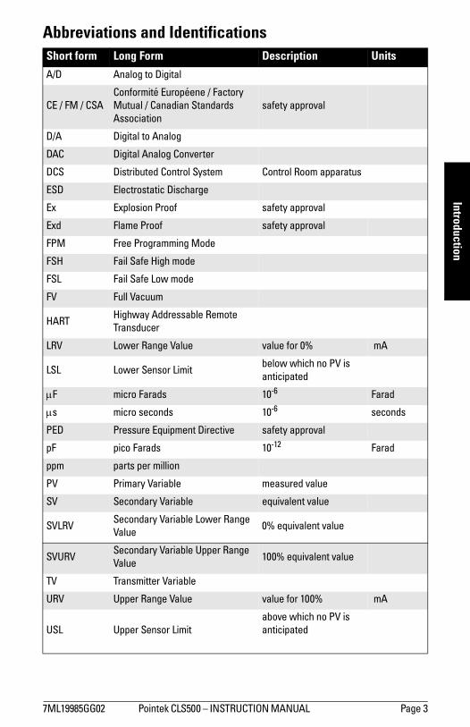
Abbreviations and IdentificationsShort form Long Form Description Units
A/D Analog to Digital
CE / FM / CSAConformité Européene / Factory Mutual / Canadian Standards Association
safety approval
D/A Digital to Analog
DAC Digital Analog Converter
DCS Distributed Control System Control Room apparatus
ESD Electrostatic Discharge
Ex Explosion Proof safety approval
Exd Flame Proof safety approval
FPM Free Programming Mode
FSH Fail Safe High mode
FSL Fail Safe Low mode
FV Full Vacuum
HARTHighway Addressable Remote Transducer
LRV Lower Range Value value for 0% mA
LSL Lower Sensor Limitbelow which no PV is anticipated
µF micro Farads 10-6 Farad
µs micro seconds 10-6 seconds
PED Pressure Equipment Directive safety approval
pF pico Farads 10-12 Farad
ppm parts per million
PV Primary Variable measured value
SV Secondary Variable equivalent value
SVLRVSecondary Variable Lower Range Value
0% equivalent value
SVURVSecondary Variable Upper Range Value
100% equivalent value
TV Transmitter Variable
URV Upper Range Value value for 100% mA
USL Upper Sensor Limitabove which no PV is anticipated
Page 4 Pointek CLS500 INSTRUCTION MANUAL 7ML19985GG02
mm
mm
m
Intr
oduc
tion
Pointek CLS500
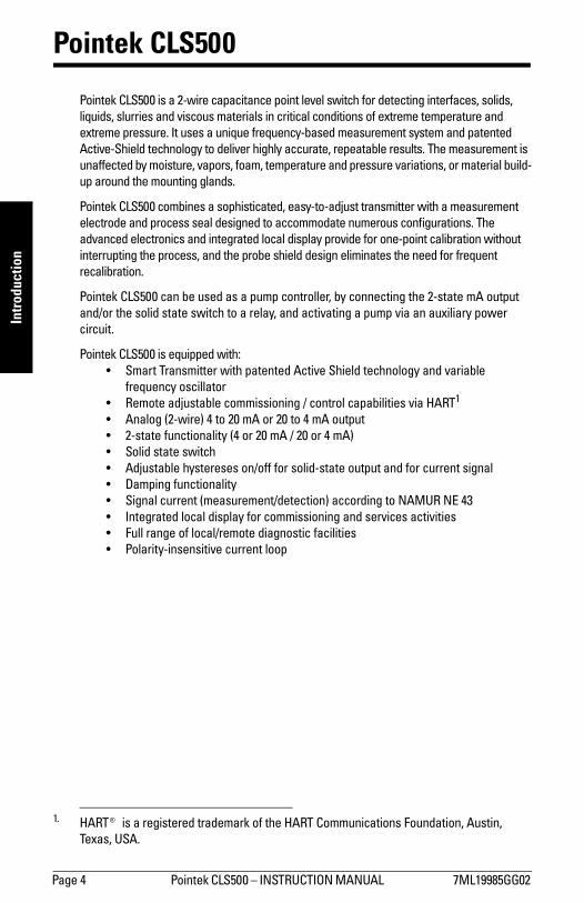
Pointek CLS500 is a 2-wire capacitance point level switch for detecting interfaces, solids, liquids, slurries and viscous materials in critical conditions of extreme temperature and extreme pressure. It uses a unique frequency-based measurement system and patented Active-Shield technology to deliver highly accurate, repeatable results. The measurement is unaffected by moisture, vapors, foam, temperature and pressure variations, or material build-up around the mounting glands.
Pointek CLS500 combines a sophisticated, easy-to-adjust transmitter with a measurement electrode and process seal designed to accommodate numerous configurations. The advanced electronics and integrated local display provide for one-point calibration without interrupting the process, and the probe shield design eliminates the need for frequent recalibration.
Pointek CLS500 can be used as a pump controller, by connecting the 2-state mA output and/or the solid state switch to a relay, and activating a pump via an auxiliary power circuit.
Pointek CLS500 is equipped with: Smart Transmitter with patented Active Shield technology and variable
frequency oscillator Remote adjustable commissioning / control capabilities via HART1
Analog (2-wire) 4 to 20 mA or 20 to 4 mA output 2-state functionality (4 or 20 mA / 20 or 4 mA) Solid state switch Adjustable hystereses on/off for solid-state output and for current signal Damping functionality Signal current (measurement/detection) according to NAMUR NE 43 Integrated local display for commissioning and services activities Full range of local/remote diagnostic facilities Polarity-insensitive current loop
1. HART® is a registered trademark of the HART Communications Foundation, Austin, Texas, USA.

7ML19985GG02 Pointek CLS500 INSTRUCTION MANUAL Page 5
mm
mm
m
Specifications
Technical Specifications: Pointek CLS500
PowerSupply voltage
maximum 33 V DC minimum 12 V DC at 3.6 mA (9.5 V DC at 22 mA)
Loop current 3.6 to 22 mA / 22 to 3.6 mA (2-wire current loop)
MountingLocation indoor/outdoor
Altitude 2000 m max.
Ambient temperature standard -40 to +85 oC (-40 to +185 oF)
ATEX-Explosion Proof -40 to +70 oC (-40 to +158oF) for T6
-40 to +85 oC (-40 to +185 oF) for T5 to T1
Relative humidity suitable for outdoor (Type 4X / NEMA 4X / IP65, IP68 enclosure)
Installation category I
Pollution degree 4
PerformanceMeasurement range
Transmitter type
MSP-2002-1 1 to 330 pF
Minimum span 1 pF
Measurement frequency 420 kHz @ Cx = 0 pF
Accuracy deviation <0.1% of actual measurement value
Repeatability 0.1% actual measurement
Temperature stability 0.15 pF (0pF) or <0.25% (typically <0.1%) of actual measurement value, whichever is greater over the full temperature range of the transmitter
specifications-CLS500.fm Page 5 Friday, September 11, 2009 1:22 PM
Page 6 Pointek CLS500 INSTRUCTION MANUAL 7ML19985GG02
mm
mm
m
Spec
ifica
tions
Safety current signalling according to NAMUR NE 43; 3.6 to 22 mA / 22 to 3.6 mA
probe input ESD protected to 55 kV inputs/outputs fully galvanically isolated polarity-insensitive current loop fully potted integrated safety barrier
Diagnostics (includes primary variable (PV) out of limitsfault alarm) system failure measurement circuit
deviation between A/D and D/A converter values check sum watch dog self-checking facility
Outputs galvanically isolated damping range 1 to 10,000
Current loop
continuous signal 4 to 20 mA / 20 to 4 mA 2-state functionality 4 or 20 mA / 20 or 4 mA, on or off time delay 1 to 100 sec. activating / de-activating adjustable hystereses (on / off) 0 to 100%, min. 1% of range
Solid-state switch
time delay 1 to 100 sec. activating / de-activating adjustable hystereses (on / off) 0 to 100%, min. 1% of range maximum switching voltage 30 V DC/30 V peak AC maximum load current 82 mA
User InterfaceLocal digital display 4 1/2 digit LCD
Rotary function switch for selecting programmable menu items
16 Positions 0 to 9, A to F
Push-buttons: RED (+), BLUE () used in conjunction with rotary switch, for programming menu items
Communications
HART 1 Communication protocol
1. HART® is a registered trademark of the HART Communication Foundation.
specifications-CLS500.fm Page 6 Friday, September 11, 2009 1:22 PM
7ML19985GG02 Pointek CLS500 INSTRUCTION MANUAL Page 7
mm
mm
m
Specifications
ElectrodesProcess connections
threaded connection AISI 316 L stainless steel 3/4, 1, 1-1/4, 1-1/2, 2 NPT, BSPT, JIS
flat-faced flanges AISI 316 L stainless steel1
Probe diameter
Rod 16 mm (0.63) or 24 mm (0.95)19 mm (0.75) High Temperature version
Probe length
Rod version (standard) up to 1000 mm (40) with 16 mm (0.63) dia. probeup to 1000 mm (40) with 24 mm (0.95) dia. probe
Rod version (High Temperature) max. active length 750 mm (29.5) with 19 mm diameter probe
Probe insulation PFA, Enamel2, Ceramic: max. length 750 mm (29.5)
Wetted PartsInsulation PFA, Enamel
Threaded Connection AISI 316 L stainless steel
Flange AISI 316 L stainless steel or Teflon3 covered
Enclosure (electronic) construction aluminum, epoxy-coated; diameter 160 mm (6.3") cable entry 2 x 1/2 NPT ingress protection Type 4X / NEMA 4X / IP65, IP68
WeightDepends on configuration.
Example:model: S-series rod: PFA insulated, 16 mm (0.63) dia., 1 m (39.4) insertion lengthweight: approx. 5 kg
1. Please see Flange Standards on page 93 for a table showing flange sizes.2. Only available as Rod version, max. length 1000 mm (39).3. Teflon® is a registered trademark of Dupont.
specifications-CLS500.fm Page 7 Friday, September 11, 2009 1:22 PM
Page 8 Pointek CLS500 INSTRUCTION MANUAL 7ML19985GG02
mm
mm
m
Spec
ifica
tions
Process
Pressure rating1 50 bar standard
Temperature rating1 +200 °C (+392 °F) standard: max. +400 oC (+752 oF)
ApprovalsCE Complies with the following European Directives:
EMC Directive 2004/108/EC,ATEX Directive 94/9/EC, andPED Directive 97/23/EC
C-TICK
Dust Ignition Proof (DIP) ATEX II 3GD (EEx nA [ib] IIC T4...T6) FM/CSA: Class I, Div. 2, Gr. A,B,C,D T4
Class II, Div. 1, Gr. E,F,G T4Class III, Div. 1, Gr. E,F,G T4
Flame-proof/ ATEX II 1/2 GD (EEx d [ia] IIC T6...T1) Explosion-proof enclosure FM: Class I, Div. 1, Gr. A,B,C,D T4
Lloyds Register of Shipping Categories ENV1, ENV2, ENV3, ENV5
1. Please refer to page 17, Temperature/ Pressure Curve chart, for specific combinations of temperature and pressure.
Notes: See Appendix F: Approvals on page 98 for details of certification. Intrinsically Safe (IS) approval [ATEX II 1 G (EEx ia IIC T4...T6),FM/CSA:Class I,
Div. 1, Gr. A,B,C,D T4] no longer available. For CLS500 devices purchased prior to June 2008 with IS approval, refer to Instruction Manual 7ML19985GG01, Edition 1.0. Go to www.siemens.com/pointek. From the CLS500 product page, search the Instructions and Manuals archive.
specifications-CLS500.fm Page 8 Friday, September 11, 2009 1:22 PM
7ML19985GG02 Pointek CLS500 INSTRUCTION MANUAL Page 9
mm
mm
m
Operation &
Application
Pointek CLS500 Transmitter
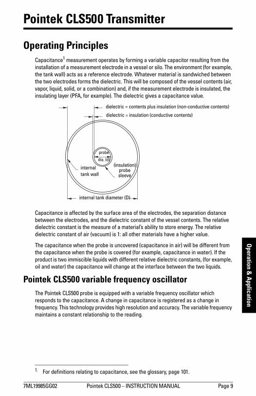
Operating PrinciplesCapacitance1 measurement operates by forming a variable capacitor resulting from the installation of a measurement electrode in a vessel or silo. The environment (for example, the tank wall) acts as a reference electrode. Whatever material is sandwiched between the two electrodes forms the dielectric. This will be composed of the vessel contents (air, vapor, liquid, solid, or a combination) and, if the measurement electrode is insulated, the insulating layer (PFA, for example). The dielectric gives a capacitance value.
Capacitance is affected by the surface area of the electrodes, the separation distance between the electrodes, and the dielectric constant of the vessel contents. The relative dielectric constant is the measure of a materials ability to store energy. The relative dielectric constant of air (vacuum) is 1: all other materials have a higher value.
The capacitance when the probe is uncovered (capacitance in air) will be different from the capacitance when the probe is covered (for example, capacitance in water). If the product is two immiscible liquids with different relative dielectric constants, (for example, oil and water) the capacitance will change at the interface between the two liquids.
Pointek CLS500 variable frequency oscillatorThe Pointek CLS500 probe is equipped with a variable frequency oscillator which responds to the capacitance. A change in capacitance is registered as a change in frequency. This technology provides high resolution and accuracy. The variable frequency maintains a constant relationship to the reading.
1. For definitions relating to capacitance, see the glossary, page 101.
dielectric = contents plus insulation (non-conductive contents)
dielectric = insulation (conductive contents)
(insulation)probe sleeve
internal tank wall
probe
dia. (d)
internal tank diameter (D)
Page 10 Pointek CLS500 INSTRUCTION MANUAL 7ML19985GG02
mm
mm
m
Ope
ratio
n &
App
licat
ion
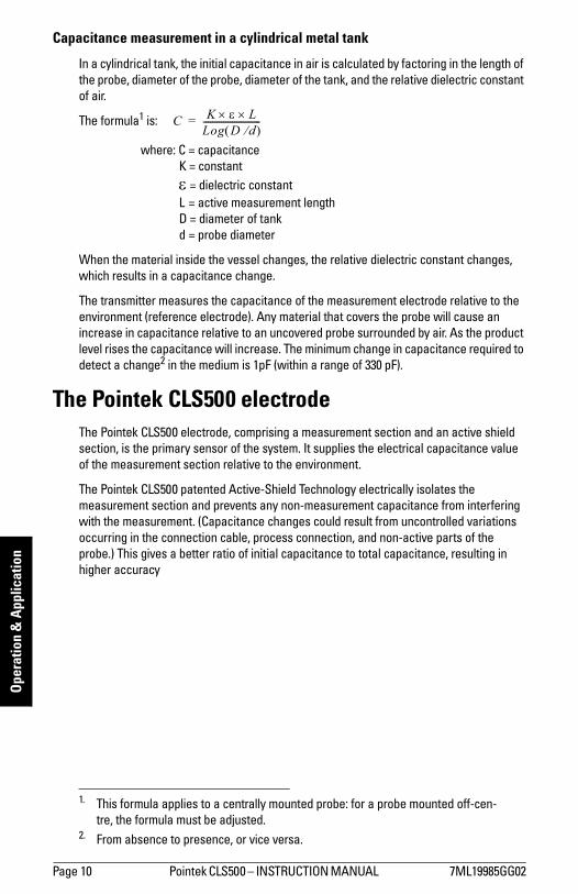
Capacitance measurement in a cylindrical metal tank
In a cylindrical tank, the initial capacitance in air is calculated by factoring in the length of the probe, diameter of the probe, diameter of the tank, and the relative dielectric constant of air.
The formula1 is:
where: C = capacitanceK = constantε = dielectric constantL = active measurement lengthD = diameter of tankd = probe diameter
When the material inside the vessel changes, the relative dielectric constant changes, which results in a capacitance change.
The transmitter measures the capacitance of the measurement electrode relative to the environment (reference electrode). Any material that covers the probe will cause an increase in capacitance relative to an uncovered probe surrounded by air. As the product level rises the capacitance will increase. The minimum change in capacitance required to detect a change2 in the medium is 1pF (within a range of 330 pF).
The Pointek CLS500 electrodeThe Pointek CLS500 electrode, comprising a measurement section and an active shield section, is the primary sensor of the system. It supplies the electrical capacitance value of the measurement section relative to the environment.
The Pointek CLS500 patented Active-Shield Technology electrically isolates the measurement section and prevents any non-measurement capacitance from interfering with the measurement. (Capacitance changes could result from uncontrolled variations occurring in the connection cable, process connection, and non-active parts of the probe.) This gives a better ratio of initial capacitance to total capacitance, resulting in higher accuracy
1. This formula applies to a centrally mounted probe: for a probe mounted off-cen-tre, the formula must be adjusted.
2. From absence to presence, or vice versa.
C K ε L××Log D d⁄( )--------------------------=

7ML19985GG02 Pointek CLS500 INSTRUCTION MANUAL Page 11
mm
mm
m
Operation &
Application
.
The measurement is further protected from interference by a buffer, which applies the frequency signal from the measurement section to the active shield section. This effectively eliminates any electrical potential difference between the shield and the measurement section and prevents additional changes in capacitance occurring.
The relative lengths of the measurement section and active shield section can be specified to suit a particular application. If the measured range will be short relative to the total length of the electrode, specify a short measurement section. This increases the
Measuring-Circuit
Measuring-Circuit
Conventional Capacitance Measurement
Pointek CLS500 with Active Shield
C1
C2
C3
R = (C1 + C2 + C3 ) + Ca(C1 + C2 + C3) + Ca + Cm
R = CaCa + Cm
Ca Ca
Cm Cm
R = Ratio between initial capacitance and total capacitance
Ca = Initial capacitance (air)
Cm = Capacitance Increase (product)
C1 = Capacitance connection point
C2 = Capacitance connection cable
C3 = Capacitance Process connection (includes active part)
frequency (f) ≈ Kcapacitance (C)
active shield
active measurement section
probe seal (inactive)
100%
0%
Pointek CLS500
buffer
empty tank
full tank

Page 12 Pointek CLS500 INSTRUCTION MANUAL 7ML19985GG02
mm
mm
m
Ope
ratio
n &
App
licat
ion
achievable resolution of the measurement, since any change in level will be greater relative to the length of the measurement section.
The entire Pointek CLS500 transmitter is potted in epoxy resin as part of the intrinsic safety protection. The potting also protects the electronics against mechanical vibration and moisture influences.
The transmitter is connected to the electrode by a mini coaxial cable, and grounded to a connection point inside the enclosure. The external ground lug on the enclosure provides a means of connecting the instrument system ground to a grounded tank. (For more detailed information on grounding requirements, please see Grounding Examples, page 33.)
The measuring range of Pointek CLS500 is 0 to 330 pF (1.0 pF ≅ 1012F).
Application: Pointek CLS500Pointek CLS500 has two modes of operation: FailSafe High or Low mode (FSH or FSL) Free Programming Mode (FPM)
Pointek CLS500 is most often used in FailSafe High/Low mode. This links the settings for triggering an alarm and a fault signal, so that you do not have to set each parameter individually: in effect, it acts as a shortcut.
Free Programming Mode allows each parameter to be set independently. In this mode, the continuous mA signal is available. FPM mode is less often employed with Pointek CLS 500.
Product or Interface detection The capacitance of the electrode system is dependent on the dielectric constant of the product surrounding the probe. By comparing the capacitances resulting from different products with different dielectric constants, it is possible to determine what product is surrounding the probe.
For products that mix together:Contamination of one product by another can be measured:
100% product A 4 mA100% product B 20 mAValues in between 4 and 20 mA represent the ratio of the two products1.
For products that do not mix:The interface between two products can be detected by the change in capacitance from one product to the other.
Note: For safety purposes, and to ensure reliable measurement signals, the external ground lug provided on the Pointek CLS500 enclosure must be firmly connected by an adequate cable to the grounded vessel.
1. Continuous measurement is only available in Free Programming Mode.

7ML19985GG02 Pointek CLS500 INSTRUCTION MANUAL Page 13
mm
mm
m
Operation &
Application
Level DetectionThe continuous 4-20 or 20-4 mA signal is proportional to the surface level of the product, with an accuracy of 0.1% of the actual measurement (for example, 1mm/m). Because the loop current is in two-state mode for fault signalling, the continuous mA signal is not available in FSH/FSL mode.
Depending on the requirements of the application, Lower Range Value (LRV - 0%) can be set to 20 mA and Upper Range Value (URV - 100%) set to 4 mA, or the reverse. The measurement takes place anywhere within that range. The LCD displays the value as mA, or pF, depending on the setting for the transmitter variable (TV). If you are using HART, you have the option to define the units (for example, meters).
2-state SwitchThe mA output can be used as a 2-state switch set to either 4 or 20 mA. It can be set to go to 4 mA if the probe is covered and 20 mA if the probe is uncovered, or the reverse.
Fault SignallingPointek CLS500 has three signal output options:
via the loop-current via the solid-state switch via HART
Via the loop current
When using the mA signal, Pointek CLS500 operates according to NAMUR standards1 for fault signalling. The fault/failure signal can be triggered by a failure in the measuring system, such as:
a checksum error a loss of signal caused by a defect in the module a short circuit in the sensor a process failure if the level exceeds the limit settings and if the unit is
programmed to detect this
You can set the Upper and Lower Sensor Limits (menus 0B and 0C) outside the Upper and Lower Range Value settings. In this case, if the process value is outside its nominal range (the span between LRV and URV), but still not at a fault/failure level, the continuous mA output will saturate to 3.8 mA or 20.5 mA. If the process value is outside the Upper or Lower Sensor Limits, this will be registered as a fault/failure.
1. See NAMUR recommendation NE 43 on page 98 for more details.
Page 14 Pointek CLS500 INSTRUCTION MANUAL 7ML19985GG02
mm
mm
m
Ope
ratio
n &
App
licat
ion
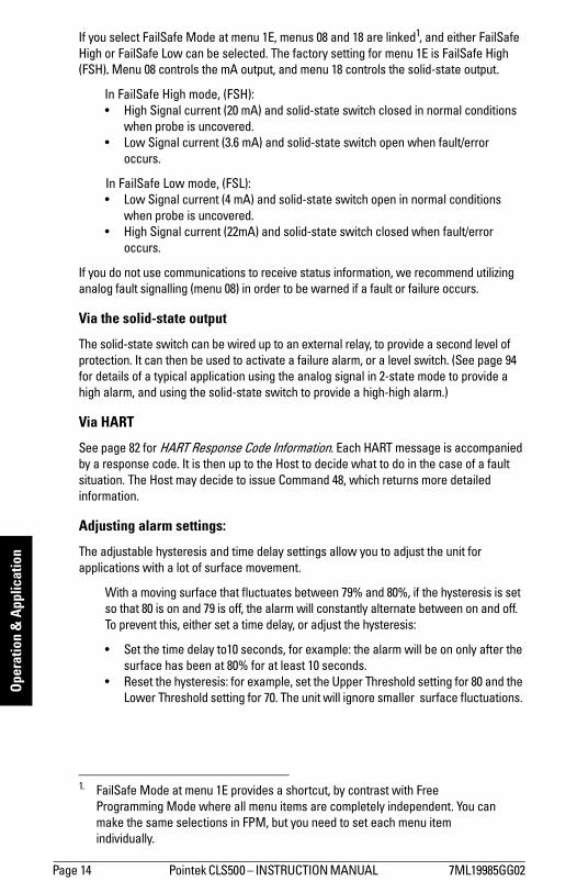
If you select FailSafe Mode at menu 1E, menus 08 and 18 are linked1, and either FailSafe High or FailSafe Low can be selected. The factory setting for menu 1E is FailSafe High (FSH). Menu 08 controls the mA output, and menu 18 controls the solid-state output.
In FailSafe High mode, (FSH): High Signal current (20 mA) and solid-state switch closed in normal conditions
when probe is uncovered. Low Signal current (3.6 mA) and solid-state switch open when fault/error
occurs.
In FailSafe Low mode, (FSL): Low Signal current (4 mA) and solid-state switch open in normal conditions
when probe is uncovered. High Signal current (22mA) and solid-state switch closed when fault/error
occurs.
If you do not use communications to receive status information, we recommend utilizing analog fault signalling (menu 08) in order to be warned if a fault or failure occurs.
Via the solid-state output
The solid-state switch can be wired up to an external relay, to provide a second level of protection. It can then be used to activate a failure alarm, or a level switch. (See page 94 for details of a typical application using the analog signal in 2-state mode to provide a high alarm, and using the solid-state switch to provide a high-high alarm.)
Via HART
See page 82 for HART Response Code Information. Each HART message is accompanied by a response code. It is then up to the Host to decide what to do in the case of a fault situation. The Host may decide to issue Command 48, which returns more detailed information.
Adjusting alarm settings:
The adjustable hysteresis and time delay settings allow you to adjust the unit for applications with a lot of surface movement.
With a moving surface that fluctuates between 79% and 80%, if the hysteresis is set so that 80 is on and 79 is off, the alarm will constantly alternate between on and off. To prevent this, either set a time delay, or adjust the hysteresis:
Set the time delay to10 seconds, for example: the alarm will be on only after the surface has been at 80% for at least 10 seconds.
Reset the hysteresis: for example, set the Upper Threshold setting for 80 and the Lower Threshold setting for 70. The unit will ignore smaller surface fluctuations.
1. FailSafe Mode at menu 1E provides a shortcut, by contrast with Free Programming Mode where all menu items are completely independent. You can make the same selections in FPM, but you need to set each menu item individually.
7ML19985GG02 Pointek CLS500 INSTRUCTION MANUAL Page 15
mm
mm
m
Probe Configuration
Pointek CLS500: Probe Configuration
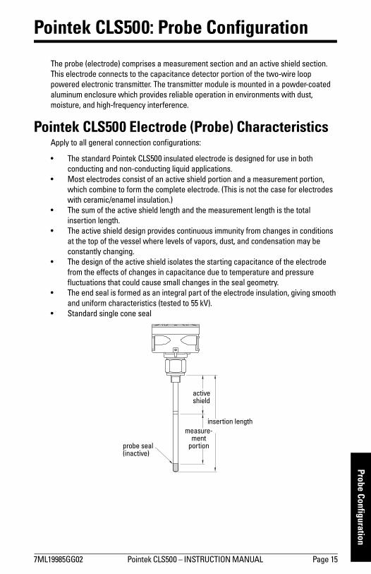
The probe (electrode) comprises a measurement section and an active shield section. This electrode connects to the capacitance detector portion of the two-wire loop powered electronic transmitter. The transmitter module is mounted in a powder-coated aluminum enclosure which provides reliable operation in environments with dust, moisture, and high-frequency interference.
Pointek CLS500 Electrode (Probe) CharacteristicsApply to all general connection configurations:
The standard Pointek CLS500 insulated electrode is designed for use in both conducting and non-conducting liquid applications.
Most electrodes consist of an active shield portion and a measurement portion, which combine to form the complete electrode. (This is not the case for electrodes with ceramic/enamel insulation.)
The sum of the active shield length and the measurement length is the total insertion length.
The active shield design provides continuous immunity from changes in conditions at the top of the vessel where levels of vapors, dust, and condensation may be constantly changing.
The design of the active shield isolates the starting capacitance of the electrode from the effects of changes in capacitance due to temperature and pressure fluctuations that could cause small changes in the seal geometry.
The end seal is formed as an integral part of the electrode insulation, giving smooth and uniform characteristics (tested to 55 kV).
Standard single cone seal
insertion length
active shield
measure-ment
portionprobe seal(inactive)

Page 16 Pointek CLS500 INSTRUCTION MANUAL 7ML19985GG02
mm
mm
m
Prob
e Co
nfig
urat
ion
High pressure and high temperature applicationsFor high temperature and pressure applications (greater than 200 bar) with conductive liquids, contact your local Siemens representative.
For more details on configuration, see Appendix E: Pointek CLS500, dimensions and application examples on page 90.
Electrode AssemblyPointek CLS500 electrodes come in a variety of formats to provide the necessary characteristics for correct mounting, chemical compatibility, temperature and pressure requirements, and dielectric constant of the medium. The main body of the manual discusses the standard configuration. Dimensions are shown in Appendix E: Pointek CLS500, dimensions and application examples, page 90.
Pointek CLS500: Standard Level Version Available with the following features:
Threaded flanges, welded flanges, and single-piece flanges HP series and HT series process seals Selections of standard ANSI and DIN flanges The most common electrode is insulated with PFA. Enamel (HP seal) is also
available. Various process connection materials Rod version only
Process ConnectionsThe standard threaded process connection with PFA insulated electrode, including the active shield, provides good results in all measurement situations within the temperature, pressure, and corrosive capabilities of the materials and seals. This remains true over a wide range of dielectric constants in both non-conducting and conducting materials.
Any standard process connection is available with Pointek CLS500, and special versions can be fabricated to match the mounting and application requirements. A wide range of threaded and flanged fittings is available. (Contact your local Siemens Milltronics representative, or check our website at www. siemens.com/processautomation).
Seal TypesThe basic internal seal for Pointek CLS500 has a conical-shaped, preloaded pressure/leak resistant construction. Up to three levels of seal protection are implemented depending on the integrity requirements of the application. A single or double cone internal seal forms one or two barriers against leaking, and a third flange face gasket is also available in the D and DD seal construction. The flange face seal also provides a design with no metal wetted parts if required.

7ML19985GG02 Pointek CLS500 INSTRUCTION MANUAL Page 17
mm
mm
m
Probe Configuration
Process Connection and Seal Configuration of Pointek CLS500
Pressure and Temperature ConsiderationsThe maximum temperature and pressure of operation for the standard Pointek CLS500 level probe is 200 °C (392 °F) and 200 bar (2900 psi). Please consult the pressure curves below for qualifications that must be applied to these maximums.
Enamel probes are recommended when the process temperature exceeds 200 °C, and/or in combination with very high pressure.
Process Connection Seal Type Seal Description
Threaded S Single Cone
Welded Flange S Single Cone
Solid Machined Flange S Single Cone
HP/HT Primary graphite seal, and glass seal
Note: Pointek CLS500 HP (high pressure version) is only supplied with enamel insulation. A primary graphite seal plus a secondary redundant seal is provided between the electrode and the instrument body.
Note: Consult your local Siemens representative if the material to be measured may be incompatible with the Pointek CLS500 materials of construction.
Page 18 Pointek CLS500 INSTRUCTION MANUAL 7ML19985GG02
mm
mm
m
Prob
e Co
nfig
urat
ion
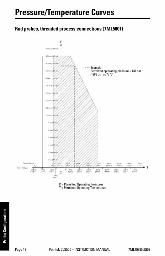
Pressure/Temperature Curves
Rod probes, threaded process connections (7ML5601)
P
T
ExamplePermitted opterating pressure = 137 bar (1988 psi) at 75 ºC
P = Permitted Operating PressuresT = Permitted Operating Temperature
7ML19985GG02 Pointek CLS500 INSTRUCTION MANUAL Page 19
mm
mm
m
Probe Configuration
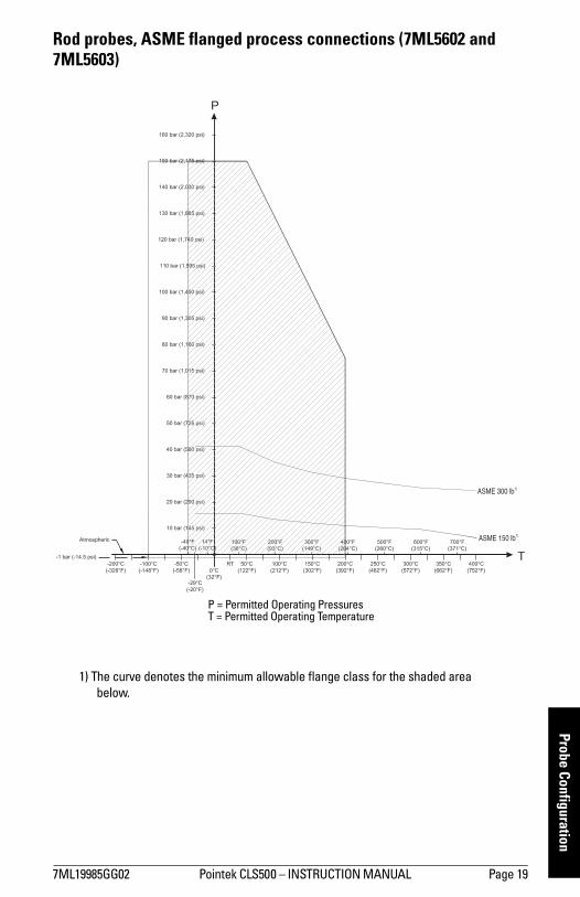
Rod probes, ASME flanged process connections (7ML5602 and 7ML5603)
1) The curve denotes the minimum allowable flange class for the shaded area below.
P
T
ASME 300 lb1)
ASME 150 lb1)
P = Permitted Operating PressuresT = Permitted Operating Temperature
Page 20 Pointek CLS500 INSTRUCTION MANUAL 7ML19985GG02
mm
mm
m
Prob
e Co
nfig
urat
ion
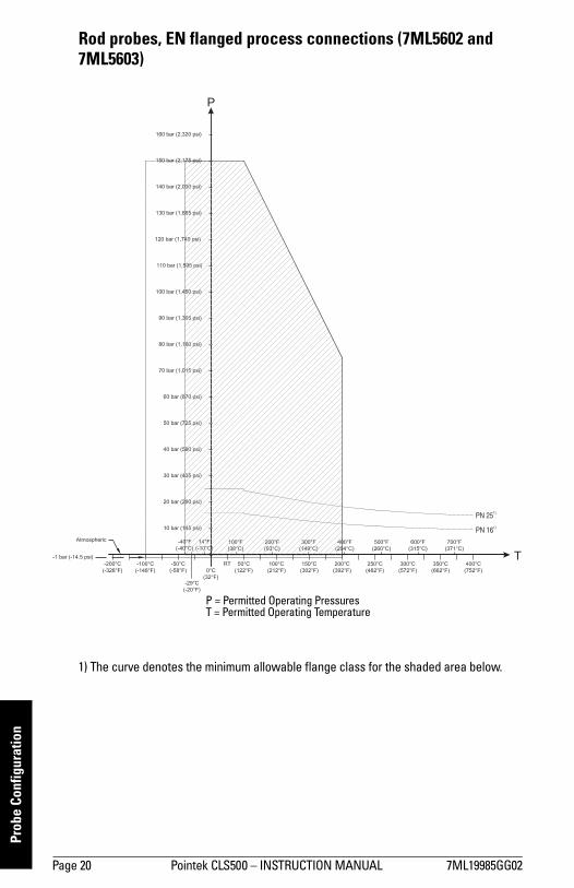
Rod probes, EN flanged process connections (7ML5602 and 7ML5603)
1) The curve denotes the minimum allowable flange class for the shaded area below.
P
T
PN 251)
PN 161)
P = Permitted Operating PressuresT = Permitted Operating Temperature
7ML19985GG02 Pointek CLS500 INSTRUCTION MANUAL Page 21
mm
mm
m
Probe Configuration
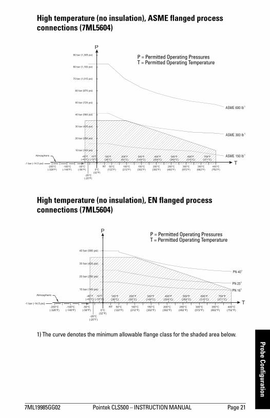
High temperature (no insulation), ASME flanged process connections (7ML5604)
High temperature (no insulation), EN flanged process connections (7ML5604)
1) The curve denotes the minimum allowable flange class for the shaded area below.
P
T
ASME 150 lb1)
ASME 300 lb1)
ASME 600 lb1)
P = Permitted Operating PressuresT = Permitted Operating Temperature
P
T
PN 401)
PN 161)
PN 251)
P = Permitted Operating PressuresT = Permitted Operating Temperature
Page 22 Pointek CLS500 INSTRUCTION MANUAL 7ML19985GG02
mm
mm
m
Prob
e Co
nfig
urat
ion
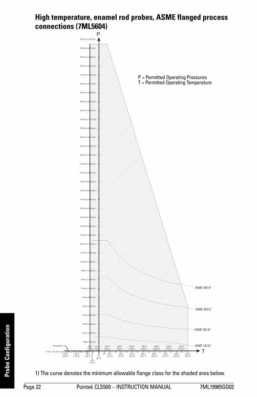
High temperature, enamel rod probes, ASME flanged process connections (7ML5604)
1) The curve denotes the minimum allowable flange class for the shaded area below.
P
T
ASME 900 lb1)
ASME 600 lb1)
ASME 300 lb1)
ASME 150 lb1)
P = Permitted Operating PressuresT = Permitted Operating Temperature
7ML19985GG02 Pointek CLS500 INSTRUCTION MANUAL Page 23
mm
mm
m
Probe Configuration
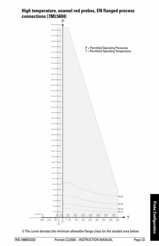
High temperature, enamel rod probes, EN flanged process connections (7ML5604)
1) The curve denotes the minimum allowable flange class for the shaded area below.
P
T
PN 631)
PN 401)
PN 251)
PN 161)
P = Permitted Operating PressuresT = Permitted Operating Temperature
Page 24 Pointek CLS500 INSTRUCTION MANUAL 7ML19985GG02
mm
mm
m
Inst
alla
tion
Installation: Pointek CLS500
Handling Electrodes
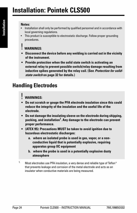
Notes: Installation shall only be performed by qualified personnel and in accordance with
local governing regulations. This product is susceptible to electrostatic discharge. Follow proper grounding
procedures.
WARNINGS: • Disconnect the device before any welding is carried out in the vicinity
of the instrument. • Provide protection when the solid state switch is activating an
external relay to prevent possible switch/relay damage resulting from inductive spikes generated by the relay coil. (See Protection for solid-state switch on page 32 for details.)
WARNINGS:• Do not scratch or gouge the PFA electrode insulation since this could
reduce the integrity of the insulation and the useful life of the electrode.
• Do not damage the insulating sleeve on the electrode during shipping, packing, and installation1. Any damage to the electrode can prevent proper performance.
• (ATEX 95): Precautions MUST be taken to avoid ignition due to hazardous electrostatic discharges:
a. where an isolated probe is used in gas, vapor, or a non-conductive liquid that is potentially explosive, requiring apparatus group IIC equipment
b. where the probe is used in a potentially explosive dusty atmosphere
1. Most electrodes use PFA insulation, a very dense and reliable type of Teflon® that prevents leakage and corrosion of the metal electrode and acts as an insulator when conductive materials are being measured.
7ML19985GG02 Pointek CLS500 INSTRUCTION MANUAL Page 25
mm
mm
m
Installation
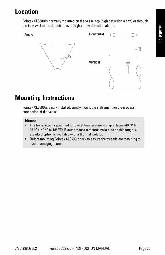
LocationPointek CLS500 is normally mounted on the vessel top (high detection alarm) or through the tank wall at the detection level (high or low detection alarm).
Mounting InstructionsPointek CLS500 is easily installed: simply mount the instrument on the process connection of the vessel.
Notes: The transmitter is specified for use at temperatures ranging from 40 °C to
85 °C (40 oF to 185 oF): if your process temperature is outside this range, a standard option is available with a thermal isolator.
Before mounting Pointek CLS500, check to ensure the threads are matching to avoid damaging them.
Angle Horizontal
Vertical

Page 26 Pointek CLS500 INSTRUCTION MANUAL 7ML19985GG02
mm
mm
m
Inst
alla
tion
Mounting Cautions
Note: These drawings are not to scale.
Multiple units
Sensors must be at least 500 mm (20) apart: mount them diagonally if vertical space is restricted.
Wall restriction
Leave at least 50 mm (2) between the probe or the probe tip and the tank wall,
500 mm (20) min.
500 mm (20) min.
500 mm (20) min.
50 mm (2) min.
50 mm (2) min.
7ML19985GG02 Pointek CLS500 INSTRUCTION MANUAL Page 27
mm
mm
m
Installation
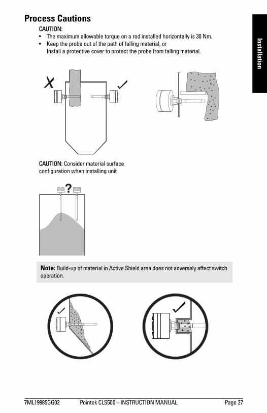
Process Cautions
Note: Build-up of material in Active Shield area does not adversely affect switch operation.
CAUTION: The maximum allowable torque on a rod installed horizontally is 30 Nm. Keep the probe out of the path of falling material, or
Install a protective cover to protect the probe from falling material.
CAUTION: Consider material surface configuration when installing unit

Page 28 Pointek CLS 500 INSTRUCTION MANUAL 7ML19985GG02
mm
mm
m
Inte
rcon
nect
ion
Interconnection: Pointek CLS500
Wiring
Supply
Pointek CLS500 uses a switched power supply circuit, which makes the most efficient use of the available power present on the terminals. If the signal current is low (4mA) the terminal voltage will be high, and if the signal current is high (20 mA) the terminal voltage may be low, due to all the resistive elements in the loop, such as the barrier and sense resistor.
WARNING:
• The DC input terminals shall be supplied from a source providing electrical isolation between the input and output, in order to meet the applicable safety requirements of IEC 61010-1.
• Observe the specifications of the examination certificate valid in your country.
• Observe the laws and regulations valid in your country for electrical installations in potentially explosive atmospheres.
• Ensure that the available power supply complies with the power supply specified on the product nameplate and specified in the examination certificate valid in your country.
• Dust-proof protection caps in the cable inlets must be replaced by suitable screw-type glands or dummy plugs, which are appropriately certified for transmitters with explosion-proof protection.
• The lid must not be opened in wet locations while the unit is powered. (A wet location is a location where water or another conductive fluid may be present and is likely to increase the risk of electric shock.)
Notes: The transmitter is powered by the current loop and needs at least 9.5-13 Volt on
the terminals: 9.5 V at 22 mA or 12 V at 3.6 mA. The maximum supply is 33 Volt. If the voltage is higher the device will shut down. The loop-circuit will withstand voltages up to 250 Vac/Vdc without any damage.

7ML19985GG02 Pointek CLS500 INSTRUCTION MANUAL Page 29
mm
mm
m
Interconnection
Examples: With a 250 Ohm sensing resistor, no barrier and negligible cable resistance, the
overall supply voltage should be at least 15.0 V. With a 250 Ohm sensing resistor, a barrier of 280 Ohm, and 20 Ohm cable
resistance (500 m), the total resistance is 550 Ohm, so the overall supply voltage should be at least 20.5 V.
For a multi-drop application, where the measuring supply is fixed to 4 mA, the voltage on the terminals of the Pointek CLS500 should be at least 12 V.
The loop circuit is completely isolated from the measurement circuit. It is designed so that the internal capacitance and inductance on the terminals are isolated, and are not a factor in safety calculations.
Cable
Selecting the correct instrumentation cable you need to know the cable length, the barrier type (if applicable), and the
measurement resistance select a cable that will give you a capacitance time constant of less than 65 µSec
Notes: To maintain reliable transfer of the HART modem signals, the RC1 time constant of
the connections should be less than 65 µSec. For output signals (from the Pointek CLS500), only the cable and barrier
resistance are relevant. For input signals the measurement resistance is also relevant.
Use twisted pair cable, screened as a pair.2
1. RC = Resistance * Capacitance2. If you use a common screen over a cable containing multiple twisted pairs, do
not use other pairs for signals that could interfere with HART signals.
Voltage drop versus mA for current transmitter operation
mA
V-su
pply
voltage drop over 250 ohm measuring resistance
voltage drop over 280 ohm in barrier
voltage drop over blocking diode in barrier
margin or voltage drop over instrument cableoperation voltage, transmitter
Page 30 Pointek CLS 500 INSTRUCTION MANUAL 7ML19985GG02
mm
mm
m
Inte
rcon
nect
ion
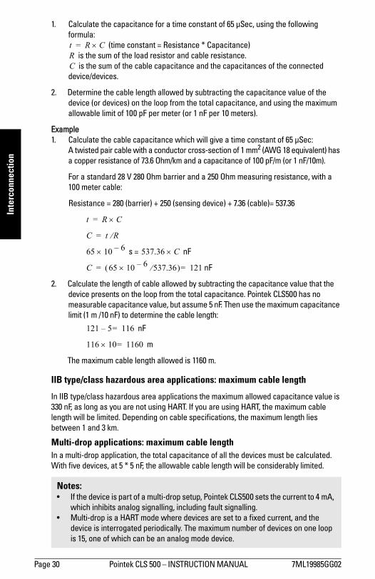
1. Calculate the capacitance for a time constant of 65 µSec, using the following formula:
(time constant = Resistance * Capacitance) is the sum of the load resistor and cable resistance. is the sum of the cable capacitance and the capacitances of the connected
device/devices.
2. Determine the cable length allowed by subtracting the capacitance value of the device (or devices) on the loop from the total capacitance, and using the maximum allowable limit of 100 pF per meter (or 1 nF per 10 meters).
Example 1. Calculate the cable capacitance which will give a time constant of 65 µSec:
A twisted pair cable with a conductor cross-section of 1 mm2 (AWG 18 equivalent) has a copper resistance of 73.6 Ohm/km and a capacitance of 100 pF/m (or 1 nF/10m).
For a standard 28 V 280 Ohm barrier and a 250 Ohm measuring resistance, with a 100 meter cable:
Resistance = 280 (barrier) + 250 (sensing device) + 7.36 (cable)= 537.36
s = nF
nF
2. Calculate the length of cable allowed by subtracting the capacitance value that the device presents on the loop from the total capacitance. Pointek CLS500 has no measurable capacitance value, but assume 5 nF. Then use the maximum capacitance limit (1 m /10 nF) to determine the cable length:
nF
m
The maximum cable length allowed is 1160 m.
IIB type/class hazardous area applications: maximum cable length
In IIB type/class hazardous area applications the maximum allowed capacitance value is 330 nF, as long as you are not using HART. If you are using HART, the maximum cable length will be limited. Depending on cable specifications, the maximum length lies between 1 and 3 km.
Multi-drop applications: maximum cable lengthIn a multi-drop application, the total capacitance of all the devices must be calculated. With five devices, at 5 * 5 nF, the allowable cable length will be considerably limited.
Notes: If the device is part of a multi-drop setup, Pointek CLS500 sets the current to 4 mA,
which inhibits analog signalling, including fault signalling. Multi-drop is a HART mode where devices are set to a fixed current, and the
device is interrogated periodically. The maximum number of devices on one loop is 15, one of which can be an analog mode device.
t R C×=RC
t R C×=
C t R⁄=
65 10 6× 537.36 C×
C 65 10 6× 537.36⁄( ) 121==
121 5 116=
116 10 1160=×

7ML19985GG02 Pointek CLS500 INSTRUCTION MANUAL Page 31
mm
mm
m
Interconnection
TerminalsPointek CLS500 is equipped with two terminal blocks, both insensitive to polarity.
One terminal block connects the instrument cable (loop power).
The second terminal block provides the solid-state switch output (solid-state relay).
Connecting Pointek CLS500The processor integrated circuit is covered by a label which contains product information and which also acts as a protective seal against moisture.
1. Loosen the retaining set-screw and remove the enclosure cover.2. Loosen the cable gland and thread the cable through it.3. Connect the power / signal conductor wires to the current loop terminal block
(any polarity). 4. Ground the enclosure (see instructions on next page for details).5. Check to ensure all connections are good.6. Tighten the cable gland to form a good seal.7. Replace the enclosure cover and tighten the retaining set-screw.
Connection Diagram
WARNING: Damage or removal of the protective label voids the warranty for the Pointek CLS500.
Note: If you plan to calibrate the unit using push-button adjustment, do so before replacing the cover.
Type:
Ser.:Date:Rev.:
Tampering voids warranty
measuring signal(mini-coaxial cable)
ground connection point for instrument system
ground lug
instrumentsystem ground
4-20 mA current-loop connection(any polarity)
solid-state switch relay (any polarity)
protective label (see warning above)
Page 32 Pointek CLS 500 INSTRUCTION MANUAL 7ML19985GG02
mm
mm
m
Inte
rcon
nect
ion
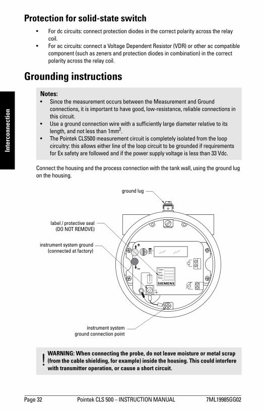
Protection for solid-state switch For dc circuits: connect protection diodes in the correct polarity across the relay
coil. For ac circuits: connect a Voltage Dependent Resistor (VDR) or other ac compatible
component (such as zeners and protection diodes in combination) in the correct polarity across the relay coil.
Grounding instructions
Connect the housing and the process connection with the tank wall, using the ground lug on the housing.
Notes: Since the measurement occurs between the Measurement and Ground
connections, it is important to have good, low-resistance, reliable connections in this circuit.
Use a ground connection wire with a sufficiently large diameter relative to its length, and not less than 1mm2.
The Pointek CLS500 measurement circuit is completely isolated from the loop circuitry: this allows either line of the loop circuit to be grounded if requirements for Ex safety are followed and if the power supply voltage is less than 33 Vdc.
WARNING: When connecting the probe, do not leave moisture or metal scrap (from the cable shielding, for example) inside the housing. This could interfere with transmitter operation, or cause a short circuit.
Type:
Ser.:Date:Rev.:
Tampering voids warranty
instrument systemground connection point
instrument system ground(connected at factory)
label / protective seal(DO NOT REMOVE)
ground lug
7ML19985GG02 Pointek CLS500 INSTRUCTION MANUAL Page 33
mm
mm
m
Interconnection
Grounding Examples: Pointek CLS500Grounding is important for two reasons:
1. To prevent interference to the signal: system grounding2. For safety purposes: safety grounding
Several common applications are illustrated. They are separated into two groups: the first group illustrates System Grounding and the second illustrates Safety Grounding.
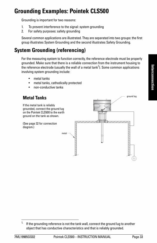
System Grounding (referencing)For the measuring system to function correctly, the reference electrode must be properly grounded. Make sure that there is a reliable connection from the instrument housing to the reference electrode (usually the wall of a metal tank1). Some common applications involving system grounding include:
metal tanks metal tanks, cathodically protected non-conductive tanks
1. If the grounding reference is not the tank wall, connect the ground lug to another object that has conductive characteristics and that is reliably grounded.
Metal TanksIf the metal tank is reliably grounded, connect the ground lug on the Pointek CLS500 to the earth ground on the tank as shown.
(See page 32 for connection diagram.)
ground lug
metal
Page 34 Pointek CLS 500 INSTRUCTION MANUAL 7ML19985GG02
mm
mm
m
Inte
rcon
nect
ion
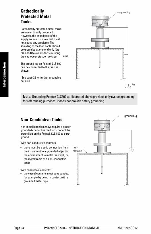
Note: Grounding Pointek CLS500 as illustrated above provides only system grounding for referencing purposes: it does not provide safety grounding.
Cathodically Protected Metal TanksCathodically protected metal tanks are never directly grounded. However, the impedance of the supply source is so low that it will not cause any problems. The shielding of the loop cable should be grounded at one end only (the tank end) to avoid short-circuiting the cathode protection voltage.
The ground lug on Pointek CLS 500 can be connected to the tank as shown.
(See page 32 for further grounding details.)
metal
ground lug
VKP
Non-Conductive TanksNon-metallic tanks always require a proper grounded conductive medium: connect the ground lug on the Pointek CLS 500 to earth ground.
With non-conductive contents:
there must be a solid connection from the instrument to a grounded object in the environment (a metal tank wall, or the metal frame of a non-conductive tank).
With conductive contents: the vessel contents must be grounded,
for example by being in contact with a grounded metal pipe.
ground lug
non-metallic
7ML19985GG02 Pointek CLS500 INSTRUCTION MANUAL Page 35
mm
mm
m
Interconnection
Safety GroundingThe safety grounding requirements are determined by the application and the connected instruments. The Pointek CLS500 transmitter does not have any special requirements due to the galvanic separation between the measurement section and the loop section.
Depending on the DCS characteristics, there are three possible grounding options: If the DCS measures the current through the loop compared to a common zero Volt
point, do not ground the negative side of the current loop because measurement inputs can be short-circuited.
If the DCS measures the current in the positive wire or connector, the negative side of the current loop can be grounded.
If the DCS has galvanically separated inputs for each measurement channel the grounding method can be chosen as required.
In hazardous applications a Stahl-type barrier is required, and it is typically mounted on a DIN rail inside a customer-supplied enclosure located in the non-hazardous area.
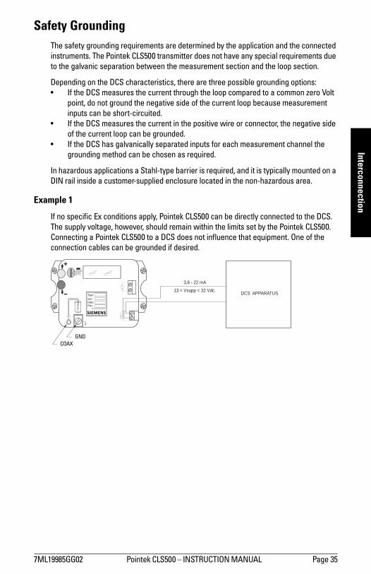
Example 1
If no specific Ex conditions apply, Pointek CLS500 can be directly connected to the DCS. The supply voltage, however, should remain within the limits set by the Pointek CLS500. Connecting a Pointek CLS500 to a DCS does not influence that equipment. One of the connection cables can be grounded if desired.
DCS APPARATUS13 < Vsupp < 32 Vdc.
3,6 - 22 mA
Type:
Ser.:Date:Rev.:
Tampering voids warranty
COAXGND
Page 36 Pointek CLS 500 INSTRUCTION MANUAL 7ML19985GG02
mm
mm
m
Inte
rcon
nect
ion
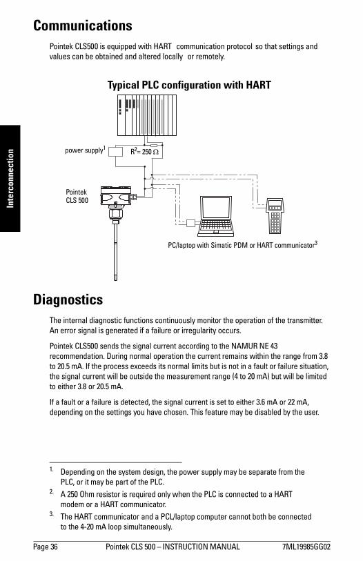
CommunicationsPointek CLS500 is equipped with HART1 communication protocol2so that settings and values can be obtained and altered locally3 or remotely.
DiagnosticsThe internal diagnostic functions continuously monitor the operation of the transmitter. An error signal is generated if a failure or irregularity occurs.
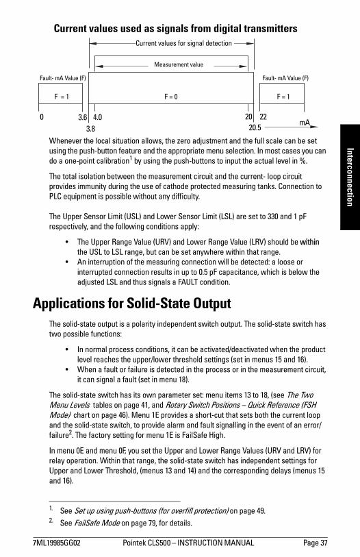
Pointek CLS500 sends the signal current according to the NAMUR NE 43 recommendation. During normal operation the current remains within the range from 3.8 to 20.5 mA. If the process exceeds its normal limits but is not in a fault or failure situation, the signal current will be outside the measurement range (4 to 20 mA) but will be limited to either 3.8 or 20.5 mA.
If a fault or a failure is detected, the signal current is set to either 3.6 mA or 22 mA, depending on the settings you have chosen. This feature may be disabled by the user.
1. Depending on the system design, the power supply may be separate from the PLC, or it may be part of the PLC.
2. A 250 Ohm resistor is required only when the PLC is connected to a HART modem or a HART communicator.
3. The HART communicator and a PCL/laptop computer cannot both be connected to the 4-20 mA loop simultaneously.
Typical PLC configuration with HART
power supply1R2= 250 Ω
Pointek CLS 500
PC/laptop with Simatic PDM or HART communicator3
7ML19985GG02 Pointek CLS500 INSTRUCTION MANUAL Page 37
mm
mm
m
Interconnection
Whenever the local situation allows, the zero adjustment and the full scale can be set using the push-button feature and the appropriate menu selection. In most cases you can do a one-point calibration1 by using the push-buttons to input the actual level in %.
The total isolation between the measurement circuit and the current- loop circuit provides immunity during the use of cathode protected measuring tanks. Connection to PLC equipment is possible without any difficulty.
The Upper Sensor Limit (USL) and Lower Sensor Limit (LSL) are set to 330 and 1 pF respectively, and the following conditions apply:
The Upper Range Value (URV) and Lower Range Value (LRV) should be within the USL to LSL range, but can be set anywhere within that range.
An interruption of the measuring connection will be detected: a loose or interrupted connection results in up to 0.5 pF capacitance, which is below the adjusted LSL and thus signals a FAULT condition.
Applications for Solid-State OutputThe solid-state output is a polarity independent switch output. The solid-state switch has two possible functions:
In normal process conditions, it can be activated/deactivated when the product level reaches the upper/lower threshold settings (set in menus 15 and 16).
When a fault or failure is detected in the process or in the measurement circuit, it can signal a fault (set in menu 18).
The solid-state switch has its own parameter set: menu items 13 to 18, (see The Two Menu Levels tables on page 41, and Rotary Switch Positions Quick Reference (FSH Mode) chart on page 46). Menu 1E provides a short-cut that sets both the current loop and the solid-state switch, to provide alarm and fault signalling in the event of an error/failure2. The factory setting for menu 1E is FailSafe High.
In menu 0E and menu 0F, you set the Upper and Lower Range Values (URV and LRV) for relay operation. Within that range, the solid-state switch has independent settings for Upper and Lower Threshold, (menus 13 and 14) and the corresponding delays (menus 15 and 16).
1. See Set up using push-buttons (for overfill protection) on page 49.2. See FailSafe Mode on page 79, for details.
Measurement value
Fault- mA Value (F)
F = 1
Fault- mA Value (F)
F = 1
mA
F = 0
Current values for signal detection
0 3.63.8
4.0 20 2220.5
Current values used as signals from digital transmitters
Page 38 Pointek CLS 500 INSTRUCTION MANUAL 7ML19985GG02
mm
mm
m
Inte
rcon
nect
ion
When the solid-state switch is to be operated as a fault/failure output (for example, for a separate shutdown system) we recommend disabling the operation for signal output (select Free Programming Mode at menu 1E, and Disabled Mode in menu 17 on page 75). When the solid-state switch control is disabled at menu 17, the threshold delay settings are unavailable.
See page 94 for details of a typical application using Pointek CLS500 to provide a high alarm via the current loop, and a high-high alarm using the solid-state switch.
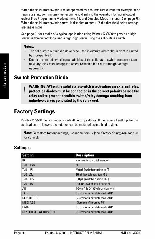
Switch Protection Diode
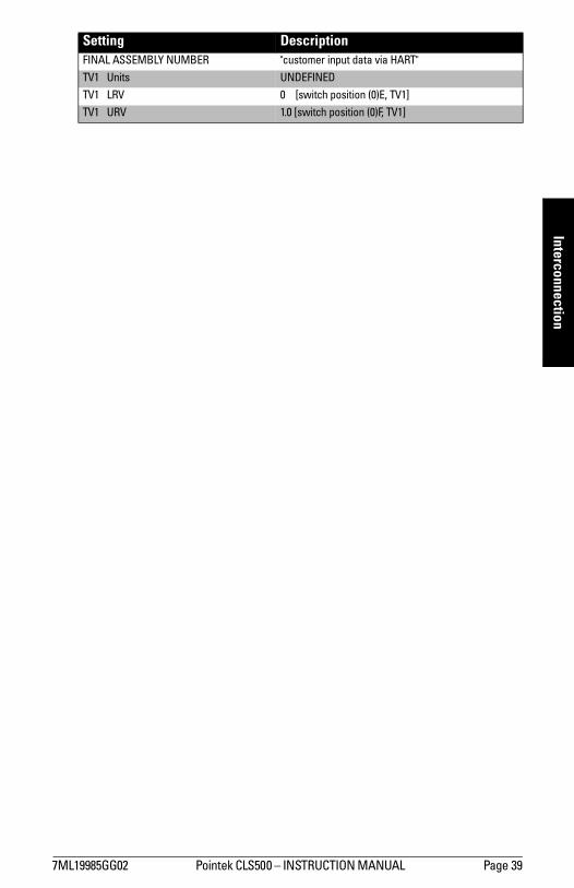
Factory SettingsPointek CLS500 has a number of default factory settings. If the required settings for the application are known, the settings can be modified during final testing.
Settings:
Notes: The solid-state output should only be used in circuits where the current is limited
by a proper load. Due to the limited switching capabilities of the solid-state switch component, an
auxiliary relay must be applied when switching high-current/high-voltage apparatus.
WARNING: When the solid state switch is activating an external relay, protection diodes must be connected in the correct polarity across the relay coil to prevent possible switch/relay damage resulting from inductive spikes generated by the relay coil.
Note: To restore factory settings, use menu item 12 (see Factory Settings on page 78 for details).
Setting DescriptionID Has a unique serial number
TV0 Units pF
TV0 USL 330 pF [switch position (0)C]
TV0 LSL 1.0 pF [switch position (0)B]
TV0 URV 330 pF [switch Position (0)F]
TV0 LRV 0.00 pF [switch Position (0)E]
AO1 4-20 mA is 0-100% [position (0)8]
TAG "customer input data via HART"
DESCRIPTOR "customer input data via HART"
MESSAGE "Siemens Milltronics P I"
DATE "customer input data via HART"
SENSOR SERIAL NUMBER "customer input data via HART"
7ML19985GG02 Pointek CLS500 INSTRUCTION MANUAL Page 39
mm
mm
m
Interconnection
FINAL ASSEMBLY NUMBER "customer input data via HART"
TV1 Units UNDEFINED
TV1 LRV 0 [switch position (0)E, TV1]
TV1 URV 1.0 [switch position (0)F, TV1]
Setting Description
Page 40 Pointek CLS500 INSTRUCTION MANUAL 7ML19985GG02
mm
mm
m
Use
r Int
erfa
ce
User Interface: Pointek CLS500
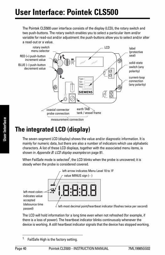
The Pointek CLS500 user interface consists of the display (LCD), the rotary switch and two push-buttons. The rotary switch enables you to select a particular item and/or variable for read-out and/or adjustment: the push-buttons allow you to select and/or alter a read-out or a value.
The integrated LCD (display)The seven-segment LCD (display) shows the value and/or diagnostic information. It is mainly for numeric data, but there are also a number of indicators which use alphabetic characters. A list of these LCD displays, together with the associated menu items, is shown in Appendix B: LCD display examples on page 81.
When FailSafe mode is selected1, the LCD blinks when the probe is uncovered; it is steady when the probe is considered covered.
The LCD will hold information for a long time even when not refreshed (for example, if there is a loss of power). The heartbeat indicator blinks continuously whenever the device is working. A still heartbeat indicator signals that the device has stopped working.
1. FailSafe High is the factory setting.
Type:
Ser.:Date:Rev.:
Tampering voids warranty
solid-state switch (any polarity)
current-loop connection (any polarity)
RED (+) push-buttonincrement value
BLUE () push-buttondecrement value
earth TABtank / vessel frame
coaxial connectorprobe connection
measurement connection
rotary switchmenu selector
LCD label (protective seal)
left-most decimal point/heartbeat indicator (flashes twice per second)
value MINUS sign ( )left-arrow indicates Menu Level 10 to 1F
left-most colon: indicates value accepted (debounce time passed)
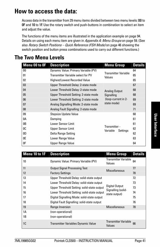
7ML19985GG02 Pointek CLS500 INSTRUCTION MANUAL Page 41
mm
mm
m
User Interface
How to access the data:Access data in the transmitter from 29 menu items divided between two menu levels: 00 to 0F and 10 to 1F. Use the rotary switch and push-buttons in combination to select an item and adjust the value.
The functions of the menu items are illustrated in the application example on page 94. Details on using each menu item are given in Appendix A: Menu Groups on page 59. (See also Rotary Switch Positions Quick Reference (FSH Mode) on page 46 showing the switch position and button press combinations used to carry out different functions.)
The Two Menu LevelsMenu 00 to 0F Description Menu Group Details00 Dynamic Value: Primary Variable (PV)
Transmitter Variable Values
64
01 Transmitter Variable select for PV 65
02 Highest/Lowest Recorded Value 65
03 Upper Threshold Delay: 2-state mode
Analog Output Signalling (loop-current in 2-state mode)
67
04 Lower Threshold Delay: 2-state mode 68
05 Upper Threshold Setting: 2-state mode 68
06 Lower Threshold Setting: 2-state mode 69
07 Analog Signalling Mode: 2-state mode 69
08 Analog Fault Signalling: 2-state mode 71
09 Stepsize Update Value
Transmitter - Variable Settings
60
0A Damping 61
0B Lower Sensor Limit 61
0C Upper Sensor Limit 62
0D Delta Range Setting 62
0E Lower Range Value 63
0F Upper Range Value 64
Menu 10 to 1F Description Menu Group Details
10 Dynamic Value: Primary Variable (PV)Transmitter Variable Values
64
11 Output Signal Processing TestMiscellaneous
77
12 Factory Settings 78
13 Upper Threshold Delay: solid-state output
Digital Output Signalling (solid-state output)
72
14 Lower Threshold Delay: solid-state output 73
15 Upper Threshold Setting: solid-state output 73
16 Lower Threshold Setting: solid-state output 74
17 Digital Signalling Mode: solid-state output 75
18 Digital Fault Signalling: solid-state output 76
19 Range Inversion Miscellaneous 78
1A (non-operational)
1B (non-operational)
1C Transmitter Variables Dynamic ValueTransmitter Variable Values
66
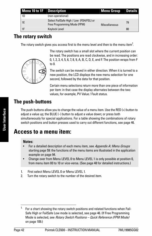
Page 42 Pointek CLS500 INSTRUCTION MANUAL 7ML19985GG02
mm
mm
m
Use
r Int
erfa
ce
The rotary switchThe rotary switch gives you access first to the menu level and then to the menu item1.
The rotary switch has a small slot where the current position can be read. The positions are read clockwise, and in increasing order: 0, 1, 2, 3, 4, 5, 6, 7, 8, 9, A, B, C, D, E, and F. The position wraps from F to 0.
The switch can be moved in either direction. When it is turned to a new position, the LCD displays the new menu selection for one second, followed by the data for that position.
Certain menu selections return more than one piece of information per item: in that case the display alternates between the two values, for example, PV Value / Fault status.
The push-buttonsThe push-buttons allow you to change the value of a menu item. Use the RED (+) button to adjust a value up; the BLUE () button to adjust a value down; or press both simultaneously for special applications. For a table showing the combinations of rotary switch positions and button presses used to carry out different functions, see page 46.
Access to a menu item:
1. First select Menu LEVEL 0 or Menu LEVEL 1. 2. Turn the rotary switch to the number of the desired item.
1D (non-operational)
1ESelect FailSafe High / Low (FSH/FSL) or Free Programming Mode (FPM) Miscellaneous
79
1F Keylock Level 80
1. For a chart showing the rotary switch positions and related functions when Fail-Safe High or FailSafe Low mode is selected, see page 46. (If Free Programming Mode is selected, see Rotary Switch Positions Quick Reference (FPM Mode) on page 109.)
Notes: For a detailed description of each menu item, see Appendix A: Menu Groups
starting page 59: the functions of the menu items are illustrated in the application example on page 94.
Change over from Menu LEVEL 0 to Menu LEVEL 1 is only possible at position 0, from menu item 00 to 10 or vice-versa. (See page 48 for detailed instructions.)
Menu 10 to 1F Description Menu Group Details
01
2
3456
7
89
ABCDE
F
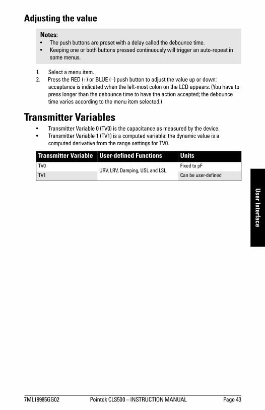
7ML19985GG02 Pointek CLS500 INSTRUCTION MANUAL Page 43
mm
mm
m
User Interface
Adjusting the value
1. Select a menu item.2. Press the RED (+) or BLUE () push button to adjust the value up or down:
acceptance is indicated when the left-most colon on the LCD appears. (You have to press longer than the debounce time to have the action accepted; the debounce time varies according to the menu item selected.)
Transmitter Variables Transmitter Variable 0 (TV0) is the capacitance as measured by the device. Transmitter Variable 1 (TV1) is a computed variable: the dynamic value is a
computed derivative from the range settings for TV0.
Notes: The push buttons are preset with a delay called the debounce time. Keeping one or both buttons pressed continuously will trigger an auto-repeat in
some menus.
Transmitter Variable User-defined Functions UnitsTV0
URV, LRV, Damping, USL and LSLFixed to pF
TV1 Can be user-defined

Page 44 Pointek CLS500 INSTRUCTION MANUAL 7ML19985GG02
mm
mm
m
Star
tup
Start-up: Pointek CLS500
Capacitance measurement systems require the instrument to be adjusted for a particular application. Two methods of adjustment are available:
push-button (for instructions, see page 49) HART (for instructions, see page 52)
Quick StartWe strongly recommend you read the full manual to use your Pointek CLS500 to its fullest potential. However, if you can bring the product to the 0% and 100% point level, you can use the Quick Start sequence on page 45 to set up the instrument and get started. (For most applications, 0% is an uncovered probe, and 100% is a covered probe.)
Pointek CLS500 is most often used in Failsafe High or Failsafe Low mode (FSH or FSL), which sets the loop current to 4 or 20 mA 2-state mode.
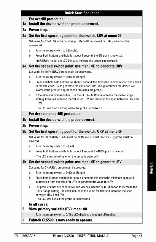
7ML19985GG02 Pointek CLS500 INSTRUCTION MANUAL Page 45
mm
mm
m
Startup
Quick Start Sequence
1aFor overfill protection:Install the device with the probe uncovered.
2a Power it up. 3a Set the first operating point for the switch, LRV at menu 0E
Set value for 0% (LRV): units must be pF (Menu 01 must read Pv = 0); probe must be uncovered.
a Turn the rotary switch to E (Empty).
b Press both buttons and hold for about 1 second: the 0% point is now set.
(In FailSafe mode, the LCD blinks to indicate the probe is uncovered.)
4a Set the second switch point: use menu 0D to generate URVSet value for 100% (URV): probe must be uncovered.
a Turn the rotary switch to D (Delta Range).
b Press and hold both buttons for about 1 second: this takes the minimum span and adds it to the value for LRV to generate the value for URV. (This guarantees the device will switch if the product approaches or touches the probe.)
c If the device is over-sensitive, use the RED (+) button to increase the Delta Range setting. (This will increase the value for URV and increase the span between LRV and URV.)
(The LCD will stop blinking when the probe is covered.)
For dry-run (underfill) protection1b Install the device with the probe covered.2b Power it up. 3b Set the first operating point for the switch, URV at menu 0F
Set value for 100% (URV): units must be pF (Menu 01 must read Pv = 0); probe must be covered.
a Turn the rotary switch to F (Full).
b Press both buttons and hold for about 1 second: the100% point is now set.
(The LCD stops blinking when the probe is covered.)
4b Set the second switch point: use menu 0D to generate LRVSet value for 0% (URV): probe must be covered.
a Turn the rotary switch to D (Delta Range).
b Press both buttons and hold for about 1 second: this takes the minimum span and subtracts it from the value for URV to generate the value for LRV.
c For products that are conductive and viscous, use the RED (+) button to increase the Delta Range setting. (This will decrease the value for LRV and increase the span between URV and LRV).(The LCD will blink if the probe is uncovered.)
5In all cases:View primary variable (PV): menu 00
Turn the rotary switch to 0. The LCD displays the actual pF reading.
6 Pointek CLS500 is now ready to operate.
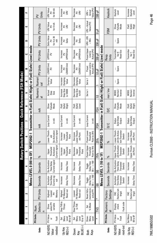
7ML1
9985
GG02
Poin
tek
CLS5
00
INST
RUCT
ION
MAN
UAL
Page
46
Ro
tary
Sw
itch
Posi
tions
– Q
uick
Ref
eren
ce (F
SH M
ode)
01
23
45
67
89
AB
CD
EF
M
enu
LEVE
L 0
(00
to O
F)
MSP
2002
-1 T
rans
mitt
er in
F(a
il) S
(afe
) H(ig
h) o
r F(a
il) S
(afe
) L(o
w) m
ode
Units
PV U
nits
Num
. Se
lect
ion
PV U
nits
Seco
nds
Seco
nds
%%
mA
mA
Num
eric
alN
umer
ica
lPV
Uni
tsPV
Uni
tsPV
Uni
tsPV
Uni
tsPV
Un
its
NO
KEYS
Valu
e re
adou
t
PV V
alue
or
Faul
t
Show
se
lect
PV
varia
ble
High
est/
Low
est
PVM
emor
y
Activ
atio
nTi
me
Dela
yCu
rren
t sig
-na
l
De-A
ctiv
atio
n Ti
me
Dela
yCu
rren
t sig
nal
Uppe
r Th
resh
old
Activ
atio
nCu
rren
t sig
nal
Low
er T
hres
h-ol
d De
-Act
ivat
ion
Curr
ent s
igna
l
Loop
Cur
rent
in m
A
Show
Fails
afe
Mod
e
Actu
alSt
epSi
ze
Dam
ping
Valu
eLO
WER
lim
itPV
UPPE
R lim
itPV
Delta
Val
uePV
fo
r 4 o
r 20
mA
LRV
Valu
ePV
fo
r 4 m
A
URV
Valu
ePV
for 2
0 m
A
Up K
ey
RED
(+)
Set
Men
u Le
vel
00 to
0F
Step
TV0
to
TVm
axHi
ghes
tPV
Mem
ory
Read
-out
Incr
ease
Dela
y Ti
me
Incr
ease
Dela
y Ti
me
Incr
ease
Up
per
Thre
shol
dPo
int
Incr
ease
Lo
wer
Th
resh
old
Poin
t
Loop
Cur
rent
in m
A
F(ai
l)
S(
afe)
H(
igh)
Incr
ease
St
ep S
ize
to 1
0000
Incr
ease
Da
mpi
ng
Valu
e
Incr
ease
PV
LO
WER
lim
it
Incr
ease
PV
UP
PER
limit
Incr
ease
PV Delta
Incr
ease
PV
LRV
Incr
ease
PV URV
Dow
n Ke
y BL
UE (
)
Set
Men
u Le
vel
10 to
1F
Step
TVm
ax
to T
V0Lo
wes
tPV
Mem
ory
Read
-out
Decr
ease
Dela
y Ti
me
Decr
ease
Dela
y Ti
me
Decr
ease
Up
per
Thre
shol
dPo
int
Decr
ease
Lo
wer
Thr
esh-
old
Poin
t
Loop
Cur
rent
in m
A
F(ai
l)
S(
afe)
L(ow
)
Decr
ease
St
ep S
ize
to 0
.01
Decr
ease
Da
mpi
ng
Valu
e
Decr
ease
PV
LO
WER
lim
it
Decr
ease
PV
UP
PER
limit
Decr
ease
PV Delta
Decr
ease
PV
LRV
Decr
ease
PV URV
Both
Ke
ys
Show
-M
enu
Leve
l
Set
%
Mod
eRe
set H
i/Lo
mem
orie
s to
actu
al P
V
Togg
leDe
lay
Tim
e00
<
> 1
00
Togg
leDe
lay
Tim
e00
<
> 1
00
Pres
et U
pper
Th
resh
old
Poin
t to
75%
Pres
et L
ower
Th
resh
old
Poin
t to
25%
Loop
Cur
rent
in m
A
Set t
o 1
Set t
o 1
Pres
etLo
wer
Lim
it to
Ac
tual
(PV)
Pres
et U
pper
Li
mit
to
Actu
al (P
V)
URV
LRV
=
Min
.LR
V =
Actu
al
Valu
e (P
V)UR
V =
Actu
al
Valu
e (P
V)
*TV
O*
0000
75%
25%
FSH
FSH
1.01
1.0 p
F33
0 pF
330
pF0
pF33
0 pF
M
enu
LEVE
L 1
(10
to 1
F)
MSP
2002
-1 T
rans
mitt
er in
F(a
il) S
(afe
) H(ig
h) o
r F(a
il) S
(afe
) L(o
w) m
ode
Units
PV U
nits
Num
eric
alFa
ctor
y Se
tting
sSe
cond
sSe
cond
s%
%O/
CO/
Cno
r / in
vRe
sp.
Units
FSM
Keyl
ock
NO
KEYS
Valu
e re
ad-o
ut
PV V
alue
or
Fau
lt
Dis
play
ch
eck
Faul
t cod
e
FAC
(fact
ory
set-
tings
)
Activ
atio
n Ti
me
Dela
y Tr
ansi
stor
Sw
itch
De-A
ctiv
atio
n Ti
me
Dela
y Tr
ansi
stor
Sw
itch)
Uppe
r Thr
esh-
old
Activ
atio
n Tr
ansi
stor
Sw
itch
Low
er T
hres
h-ol
d De
-Act
iva-
tion
Tran
sist
or
Switc
h
Stat
us
Solid
Sta
te
Outp
ut
Show
Fa
ilsaf
e M
ode
MOD
EN
orm
al /
Inve
rse
Sp
are
Sp
are
Tran
smitt
er
Var 0
Re
ad-O
ut
Sp
are
Show
Fails
afe
M
ode
Keyl
ock
Leve
l
Up K
ey
RED
(+)
Set M
enu
Leve
l00
to 0
F
FAC
(fact
ory
set-
tings
)
Incr
ease
Dela
y Ti
me
Incr
ease
Dela
y Ti
me
Incr
ease
Up
per T
hres
h-ol
d Po
int
Incr
ease
Lo
wer
Thr
esh-
old
Poin
t
Stat
us
Solid
Sta
te
Outp
ut
F(ai
l)
S(
afe)
H(
igh)
MOD
EN
orm
al /
Inve
rse
Tran
smitt
er
Var 1
Re
ad-O
ut
F(ai
l)
S(af
e)
H(ig
h
Incr
ease
Ke
yloc
k Le
vel
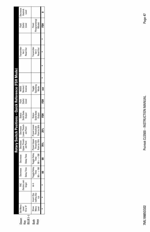
7ML1
9985
GG02
Poin
tek
CLS5
00
INST
RUCT
ION
MAN
UAL
Page
47
Dow
n Ke
y BL
UE (
)
Set M
enu
Leve
l 10
to 1
F
FAC
(fact
ory
set-
tings
)
Decr
ease
Dela
y Ti
me
Decr
ease
Dela
y Ti
me
Decr
ease
Up
per T
hres
h-ol
d Po
int
Decr
ease
Lo
wer
Thr
esh-
old
Poin
t
Stat
us
Solid
Sta
te
Outp
ut
F(ai
l)
S(
afe)
L(ow
)
MOD
EN
orm
al /
Inve
rse
Tran
smitt
er
Var 2
Re
ad-O
ut
F(ai
l)
S(af
e)
L(
ow)
Decr
ease
Ke
yloc
k Le
vel
Both
Ke
ys
Show
M
enu
Leve
l
Inve
rt S
ig-
nalli
ng S
ta-
tus
do it
To
ggle
Del
ay
Tim
e 00
< -
> 10
0
Togg
le D
elay
Ti
me
00 <
- >
100
Pres
et U
pper
Th
resh
old
Poin
t to
75%
Pres
et L
ower
Th
resh
old
Poin
t to
25%
Stat
us
Solid
Sta
te
Outp
ut
Togg
le
Ope
ratin
g M
ode
Tran
smitt
er
Var 3
Re
ad-O
ut
F(re
e)
P(ro
gram
min
g)
M(o
de)
**
*00
0075
%25
%FS
HFS
Hno
r*
**
*FS
H0
Ro
tary
Sw
itch
Posi
tions
– Q
uick
Ref
eren
ce (F
SH M
ode)

Page 48 Pointek CLS500 INSTRUCTION MANUAL 7ML19985GG02
mm
mm
m
Star
tup
Menu levels 0 and 1Menu level 00 to 0F is the default start-up setting after power is applied or after a reset. Menu Level 10 through 1F is flagged in the LCD by an left-arrow indicator in the upper left corner of the LCD.
To change from menu 00 to menu 10:1. Set the rotary switch to 0. 2. Press and hold the BLUE () button.3. While the button is pressed, the display shows : M 10 followed by : SEL 1,
indicating that the current menu level is now 10 to 1F. A left-arrow is displayed in the top left corner of the LCD.
4. When the button is released, the LCD displays PV (primary variable) and the left-arrow remains visible.
To change from menu 10 to menu 00:1. Make sure the rotary switch is set to 0.2. Press and hold the RED (+) button.3. While the button is pressed, the display shows : M 00 followed by : SEL 0,
indicating that the current menu level is 00 to 0F. No left-arrow is displayed in the top left corner of the LCD.
4. When the button is released, the LCD displays PV.
In menu 00 or 10, to see the current menu level selection, briefly press one of the buttons (less than a second): the current selection is momentarily displayed.
Start up using push-button set up: (overview) Check that Keylock level is set to enable calibration Check that the transmitter variable is set to TV0: units as pF Set the first switch point (set the value for 0%) Set the overfill protection1 (set the value for 100%) Set display for dynamic PV (primary variable): select values displayed as units (pF) Pointek CLS500 is ready to operate
Notes: Check the menu level when using the rotary switch to select a menu item: the left-
arrow in the top left corner of the LCD indicates menu level 1. The rotary switch must be set to 0, in order to change from one menu to the other. Hold the RED (+) or BLUE() buttons for longer than the preset delay, or debounce
time, when altering a value: the debounce time is generally about a second, but varies from one menu item to another.
Keylock level (menu 1F) must be set to 0 (no restrictions) to enable you to change settings.
1. For instructions on setting up Pointek CLS500 or dry-run protection, see page 50.
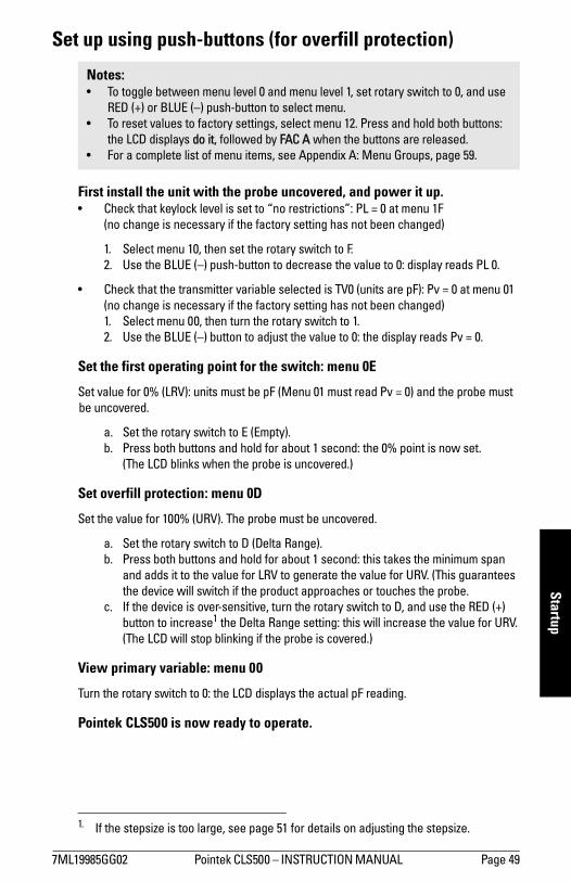
7ML19985GG02 Pointek CLS500 INSTRUCTION MANUAL Page 49
mm
mm
m
Startup
Set up using push-buttons (for overfill protection)
First install the unit with the probe uncovered, and power it up. Check that keylock level is set to no restrictions: PL = 0 at menu 1F
(no change is necessary if the factory setting has not been changed)
1. Select menu 10, then set the rotary switch to F.2. Use the BLUE () push-button to decrease the value to 0: display reads PL 0.
Check that the transmitter variable selected is TV0 (units are pF): Pv = 0 at menu 01(no change is necessary if the factory setting has not been changed)1. Select menu 00, then turn the rotary switch to 1.2. Use the BLUE () button to adjust the value to 0: the display reads Pv = 0.
Set the first operating point for the switch: menu 0E
Set value for 0% (LRV): units must be pF (Menu 01 must read Pv = 0) and the probe must be uncovered.
a. Set the rotary switch to E (Empty).b. Press both buttons and hold for about 1 second: the 0% point is now set.
(The LCD blinks when the probe is uncovered.)
Set overfill protection: menu 0D
Set the value for 100% (URV). The probe must be uncovered.
a. Set the rotary switch to D (Delta Range).b. Press both buttons and hold for about 1 second: this takes the minimum span
and adds it to the value for LRV to generate the value for URV. (This guarantees the device will switch if the product approaches or touches the probe.
c. If the device is over-sensitive, turn the rotary switch to D, and use the RED (+) button to increase1 the Delta Range setting: this will increase the value for URV.(The LCD will stop blinking if the probe is covered.)
View primary variable: menu 00
Turn the rotary switch to 0: the LCD displays the actual pF reading.
Pointek CLS500 is now ready to operate.
Notes: To toggle between menu level 0 and menu level 1, set rotary switch to 0, and use
RED (+) or BLUE () push-button to select menu. To reset values to factory settings, select menu 12. Press and hold both buttons:
the LCD displays do it, followed by FAC A when the buttons are released. For a complete list of menu items, see Appendix A: Menu Groups, page 59.
1. If the stepsize is too large, see page 51 for details on adjusting the stepsize.
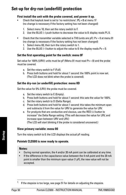
Page 50 Pointek CLS500 INSTRUCTION MANUAL 7ML19985GG02
mm
mm
m
Star
tup
Set-up for dry-run (underfill) protection
First install the unit with the probe covered, and power it up. Check that keylock level is set to no restrictions: PL = 0 at menu 1F
(no change is necessary if the factory setting has not been changed)
1. Select menu 10, then set the rotary switch to F.2. Use the BLUE () push-button to decrease the value to 0: display reads PL 0.
Check that the transmitter variable selected is TV0 (units are pF): Pv = 0 at menu 01(no change is necessary if the factory setting has not been changed)1. Select menu 00, then turn the rotary switch to 1.2. Use the BLUE () button to adjust the value to 0: the display reads Pv = 0.
Set the first operating point for the switch: menu 0F
Set value for 100% (URV): units must be pF (Menu 01 must read Pv = 0) and the probe must be covered.
a. Set the rotary switch to F (Full).b. Press both buttons and hold for about 1 second: the 100% point is now set.
(The LCD does not blink when the probe is covered).
Set the dry-run (or underfill) protection: menu 0D
Set the value for 0% (LRV): the probe must be covered.
a. Set the rotary switch to E (Empty).b. Press both buttons and hold for about 1 second: this sets the value for 100%.c. Set the rotary switch to D (Delta Range).d. Press both buttons and hold for about 1 second: this takes the minimum span
and subtracts it from the value for URV to generate the value for LRV. e. For products that are conductive and viscous, use the RED (+) button to
increase1 the Delta Range setting. (This will decrease the value for LRV, and increase span between URV and LRV.)(The LCD will start blinking if the probe is considered uncovered.)
View primary variable: menu 00
Turn the rotary switch to 0: the LCD displays the actual pF reading.
Pointek CLS500 is now ready to operate.
1. If the stepsize is too large, see page 51 for details on adjusting the stepsize.
Notes: During normal operation, the 4 and/or 20 mA point can be calibrated at any time. If the difference in the capacitance value between the 4 mA point and the 20 mA
point is smaller than the minimum span value (1 pF), the new value will not be accepted.
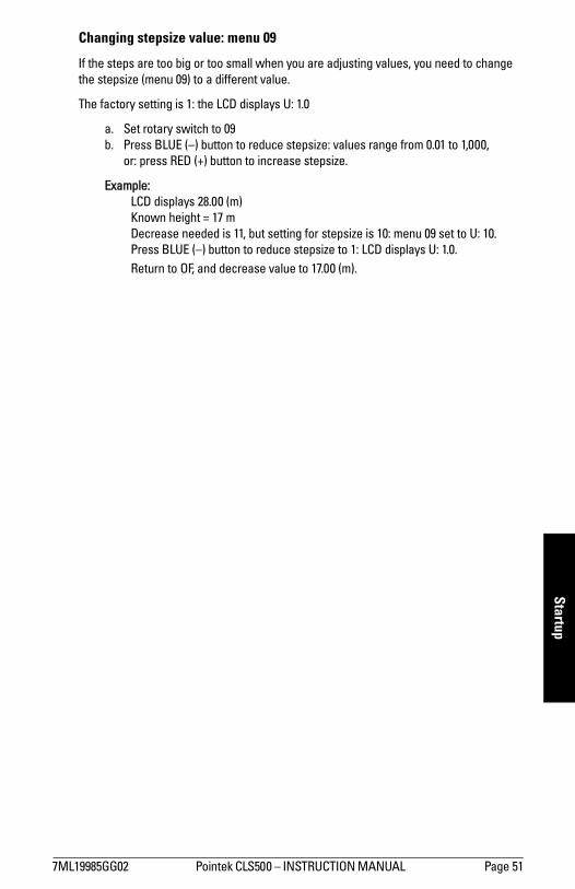
7ML19985GG02 Pointek CLS500 INSTRUCTION MANUAL Page 51
mm
mm
m
Startup
Changing stepsize value: menu 09
If the steps are too big or too small when you are adjusting values, you need to change the stepsize (menu 09) to a different value.
The factory setting is 1: the LCD displays U: 1.0
a. Set rotary switch to 09b. Press BLUE () button to reduce stepsize: values range from 0.01 to 1,000,
or: press RED (+) button to increase stepsize.
Example:LCD displays 28.00 (m)Known height = 17 mDecrease needed is 11, but setting for stepsize is 10: menu 09 set to U: 10. Press BLUE () button to reduce stepsize to 1: LCD displays U: 1.0. Return to OF, and decrease value to 17.00 (m).

Page 52 Pointek CLS500 INSTRUCTION MANUAL 7ML19985GG02
mm
mm
m
Star
tup
Setup using HARTYou can set up Pointek CLS500 transmitter using HART, with a HART communicator; a laptop running Simatic PDM, or with the Host system (DCS). The local circumstances determine the easiest method. If you can bring the product to the 0% and 100% point level, setup is simple. (Either the probe state is uncovered at 0%, and covered at 100%, or the reverse.)
Examples of set up using a Rosemount 275 hand-held communicator, fitted with the GENERIC device descriptor:
Example 1
For situations where the level of the product can be easily adjusted to 0 and 100%.
First install Pointek CLS500, then power it up: the probe must be uncovered.
1. Switch on the 275 and request connection with Pointek CLS500.
a. Select: Onlineb. Select: Device setupc. Select: Diag serviced. Select: Calibratione. Select: Apply values
(Display reads: Loop should be removed from automatic control. Select: Ok)f. Select: 4 mA g. Select: Apply new 4 mA input
2. Bring the level of the product to the level which corresponds with 4 mA.
a. Select: Read new valueb. Select: Set as 4 mA value: the 4 mA point has now been set.c. Select: 20 mAd. Select: Apply new 20 mA input
3. Bring the level of the product to the level which corresponds with 20 mA.
a. Select: Read new valueb. Select: Set as 20 mA value: the 20 mA point has now been set.c. Select: Exit
(Display reads: Loop may be returned to automatic control. Select: Ok)
Setup is complete.
Notes: Use the arrow keys, up, down, forward, and back to navigate within the menus. Use the back arrow to return to previous screens.

7ML19985GG02 Pointek CLS500 INSTRUCTION MANUAL Page 53
mm
mm
m
Startup
Example 2
For situations where the capacitance values are known in advance.
1. Switch on the 275 and establish connection with Pointek CLS500.
a. Select: Onlineb. Select: Device setupc. Select: Diag serviced. Select: Calibratione. Select: Enter valuesf. Select: PV LRV
2. Enter required capacitance value for 0% of the range.
a. Select: PV URV
3. Enter required capacitance value for 100% of the range.
a. Select: Send (the values are now sent)b. Select: Put loop in manualc. Select: Return loop to auto
If the DCS and/or the 275 are fitted with the Device Descriptor for Pointek CLS500, more functions can be used.
The available functions are:
Number Description(48) Read Additional Transmitter Status
(38) Reset Configuration Changed Flag
(128) Set Alarm Select
(129) Adjust for Product Build-up on Sensor
(130) Read FailSafe mode
(131) Return device configuration info
(132) Set Variable Upper Limit
(133) Set Variable Lower Limit
(134) Write keylock value
(135) Read keylock value
(138) Write simulation time and value
(139) Read simulation time and value
(140) Write TV1 Units, URV and LRV
(141) Read TV1 Units, URV and LRV
(144) Reset Max/Min recorded PV
(145) Read Max/Min recorded PV
(150) Write analog signalling mode
(151) Read analog signalling mode
(152) Write digital signalling mode
(153) Read digital signalling mode
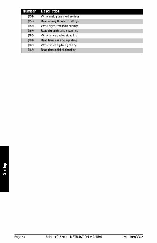
Page 54 Pointek CLS500 INSTRUCTION MANUAL 7ML19985GG02
mm
mm
m
Star
tup
(154) Write analog threshold settings
(155) Read analog threshold settings
(156) Write digital threshold settings
(157) Read digital threshold settings
(160) Write timers analog signalling
(161) Read timers analog signalling
(162) Write timers digital signalling
(163) Read timers digital signalling
Number Description

7ML19985GG02 Pointek CLS500 INSTRUCTION MANUAL Page 55
mm
mm
m
Maintenance
Maintenance
Test FunctionAuto Self-testing
Pointek CLS500 continuously performs a variety of tests to verify that the device is functioning correctly. These include a test where a known capacitor is applied to the input of the device. The internal results must match the known capacitance value. If a deviation is detected the Fault/Failure can be flagged with a pre-set loop-current (user configurable) and as a status in each HART message.
Manual testing
In order to test the proper processing of signals in PLC/DCS equipment, Pointek CLS500 allows you to invert the output signal status. In Menu 11, when both buttons are pressed simultaneously, the signal outputs switch to their opposite state. When the buttons are released, the outputs revert to the initial state.
If no Fault/Failure is present and no buttons are pressed, the display for menu 11 alternates between two test patterns which together illuminate all the segments of the display. If the loop-current control is in analog mode the loop current will hold the last value, during this test.
InspectionsUnder normal circumstances, the Pointek CLS500 transmitter requires no maintenance. However, we recommend that you schedule periodic inspections of the Pointek CLS500.
The inspection can be subdivided into two parts:
1. Visual Inspection: confirm the following conditions:
a. Inside enclosure is clean and dry.
b. Enclosure sealing is intact and functioning properly (not hardened).
c. All screw connections are tight.
d. Ground connections inside the housing are solid.
e. Ground connections outside the housing are solid.
f. The coaxial connector is free of dirt or deposits.
g. No cables or wires are jammed under the cover.
2. Functional Checks
a. Check for required minimum terminal voltage (see page 28 for supply voltage requirements).
Note: If a Fault or Failure is present, its signal will take precedence over the test function.
Page 56 Pointek CLS500 INSTRUCTION MANUAL 7ML19985GG02
mm
mm
m
Mai
nten
ance
b. Confirm that Menu 08 is set to enable analog fault signalling: display should read F: Hi or F: Lo. (If there is a fault condition, it will read F= Hi or F= Lo, when buttons are released.)
c. Check that the current goes to the alarm position (3.6 or 22 mA) if the coaxial plug is unplugged: at menu 00, the LCD should display ooL. After the test, replace the coaxial plug.
d. Confirm that Menu 18 is set to enable digital fault signalling: the LCD should display F= cc or F= co, when buttons are released.
e. Check that the solid-state output goes to the alarm position (open/close) if the coaxial plug is unplugged. After the test, replace the plug.
f. Via HART:Check that the PV goes to 0 pF when the coaxial plug is unplugged, (±0.15 pF is allowed). If it does, switch the output current to 4 mA and check the current through the loop, then to 20 mA and check the current through the loop. After the test, replace the plug.
7ML19985GG02 Pointek CLS500 INSTRUCTION MANUAL Page 57
mm
mm
m
Troubleshooting
Troubleshooting: Pointek CLS500
If you are unable to change settings:
Check that keylock level (menu 1F) is set to 0: the display should read PL = 0. Check that menu 01 is set appropriately: If Pv = 1, changes can only be made via
HART.
If you can change settings:
Reset menu 12 to factory settings: press both buttons, and the display should read FAC A when buttons are released.
If the LCD displays a negative reading, typically around 100 pF, this often indicates a short circuit in the probe assembly:
Check the enclosure and make sure no water has got in. Check that all the connections in the probe assembly are solid.
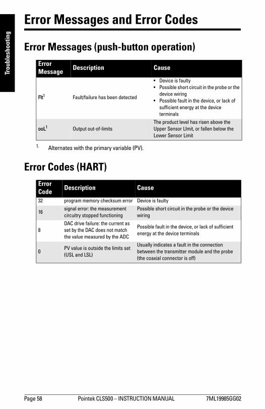
Page 58 Pointek CLS500 INSTRUCTION MANUAL 7ML19985GG02
mm
mm
m
Trou
bles
hoot
ing
Error Messages and Error Codes
Error Messages (push-button operation)
Error Codes (HART)
Error Message Description Cause
Flt1
1. Alternates with the primary variable (PV).
Fault/failure has been detected
Device is faulty Possible short circuit in the probe or the
device wiring Possible fault in the device, or lack of
sufficient energy at the device terminals
ooL1 Output out-of-limits The product level has risen above the Upper Sensor LImit, or fallen below the Lower Sensor Limit
Error Code Description Cause
32 program memory checksum error Device is faulty
16signal error: the measurement circuitry stopped functioning
Possible short circuit in the probe or the device wiring
8DAC drive failure: the current as set by the DAC does not match the value measured by the ADC
Possible fault in the device, or lack of sufficient energy at the device terminals
0PV value is outside the limits set (USL and LSL)
Usually indicates a fault in the connection between the transmitter module and the probe (the coaxial connector is off)

7ML19985GG02 Pointek CLS500 INSTRUCTION MANUAL Page 59
mm
mm
m
Appendix A
Appendix A: Menu Groups
The data in the transmitter is accessible as 291 menu items divided between two menu levels: 00 to 0F and 10 to 1F. You can switch between the two levels at position 00 and 10.
The menu items are grouped according to function, with a detailed description of each item. The menu groups are shown below.
1. Only 29 of the possible 32 items are currently used.
Transmitter – Variable SettingsStepsize Update Value
DampingLower
Sensor LimitUpper
Sensor LimitDelta Range
SettingLower
Range ValueUpper
Range Value
Menu 09 Menu 0A Menu 0B Menu 0C Menu 0D Menu 0E Menu 0F
see page 60 see page 61 see page 61 see page 62 see page 62 see page 63 see page 64
Transmitter – Variable ValuesDynamic Value:
Primary Variable (PV)Highest Lowest Recorded Value
Transmitter Variable select for PV
Transmitter Variables Dynamic Value
Menus 00 and 10 Menu 02 Menu 01 Menu 1C
see page 64 see page 65 see page 65 see page 66
Analog Output Signalling (loop current in 2-state mode) Upper
Threshold Delay
Lower Threshold
Delay
Upper Threshold
Setting
Lower Threshold
Setting
Analog Signalling
Mode
Analog Fault
Signalling
Menu 03 Menu 04 Menu 05 Menu 06 Menu 07 Menu 08
see page 67 see page 68 see page 68 see page 69 see page 69 see page 71
Digital Output Signalling (solid-state output) Upper
Threshold Delay
Lower Threshold
Delay
Upper Threshold
Setting
Lower Threshold
Setting
Digital Signalling
Mode
Digital Fault
Signalling
Menu 13 Menu 14 Menu 15 Menu 16 Menu 17 Menu 18
see page 72 see page 73 see page 73 see page 74 see page 75 see page 76
Miscellaneous Output Signal
Processing TestFactory Settings Range Inversion FailSafe Mode Keylock Level
Menu 11 Menu 12 Menu 19 Menu 1E Menu 1F
see page 77 see page 78 see page 78 see page 79 see page 80
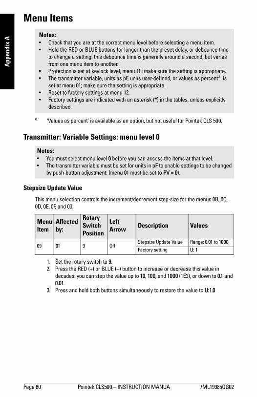
Page 60 Pointek CLS500 INSTRUCTION MANUA 7ML19985GG02
mm
mm
m
App
endi
x A
Menu Items
Transmitter: Variable Settings: menu level 0
Stepsize Update Value
This menu selection controls the increment/decrement step-size for the menus 0B, 0C, 0D, 0E, 0F, and 03.
1. Set the rotary switch to 9. 2. Press the RED (+) or BLUE () button to increase or decrease this value in
decades: you can step the value up to 10, 100, and 1000 (1E3), or down to 0.1 and 0.01.
3. Press and hold both buttons simultaneously to restore the value to U:1.0
Notes: Check that you are at the correct menu level before selecting a menu item. Hold the RED or BLUE buttons for longer than the preset delay, or debounce time
to change a setting: this debounce time is generally around a second, but varies from one menu item to another.
Protection is set at keylock level, menu 1F: make sure the setting is appropriate. The transmitter variable, units as pF, units user-defined, or values as percenta, is
set at menu 01; make sure the setting is appropriate. Reset to factory settings at menu 12. Factory settings are indicated with an asterisk (*) in the tables, unless explicitly
described.
a. Values as percent is available as an option, but not useful for Pointek CLS 500.
Notes: You must select menu level 0 before you can access the items at that level. The transmitter variable must be set for units in pF to enable settings to be changed
by push-button adjustment: (menu 01 must be set to PV = 0).
Menu Item
Affected by:
Rotary Switch Position
Left Arrow Description Values
09 01 9 OffStepsize Update Value Range: 0.01 to 1000
Factory setting U: 1
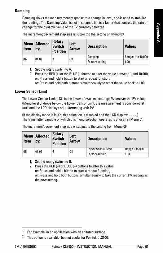
7ML19985GG02 Pointek CLS500 INSTRUCTION MANUAL Page 61
mm
mm
m
Appendix A
Damping
Damping slows the measurement response to a change in level, and is used to stabilize the reading1. The Damping Value is not in seconds but is a factor that controls the rate of change for the dynamic value of the TV currently selected.
The increment/decrement step size is subject to the setting on Menu 09.
1. Set the rotary switch to A. 2. Press the RED (+) or the BLUE () button to alter the value between 1 and 10,000.
or: Press and hold a button to start a repeat function,or: Press and hold both buttons simultaneously to reset the value back to 1.00.
Lower Sensor Limit
The Lower Sensor Limit (LSL) is the lower of two limit settings. Whenever the PV value (Menu level 0) drops below the Lower Sensor Limit, the measurement is considered at fault and the LCD displays ooL, alternating with PV.
(If the display mode is in %2, this selection is disabled and the LCD displays - - - -.) The transmitter variable on which this menu selection operates is chosen in Menu 01.
The increment/decrement step size is subject to the setting from Menu 09.
1. Set the rotary switch to B. 2. Press the RED (+) or BLUE () buttons to alter this value.
or: Press and hold a button to start a repeat function,or: Press and hold both buttons simultaneously to take the current PV reading as the new setting.
1. For example, in an application with an agitated surface.
Menu Item
Affected by:
Rotary Switch Position
Left Arrow Description Values
0A 01, 09 A OffDamping Range: 1 to 10,000
Factory setting 1.00
2. This option is available, but not useful for Pointek CLS500.
Menu Item
Affected by:
Rotary Switch Position
Left Arrow Description Values
0B 01, 09 B OffLower Sensor Limit Range 0 to 330
Factory setting 1.00

Page 62 Pointek CLS500 INSTRUCTION MANUA 7ML19985GG02
mm
mm
m
App
endi
x A
Upper Sensor Limit
The Upper Sensor Limit (USL) is the upper of two limit settings. Whenever the PV value (Menu Level 0) rises above the upper limit setting, the measurement is considered at fault and the LCD displays ooL, alternating with PV.
(If the display mode is in %1, this selection is disabled and the LCD displays - - - -.) The transmitter variable on which this menu selection operates is chosen in Menu 01.
The increment/decrement step size is subject to the setting from Menu 09.
1. Set the rotary switch to C. 2. Press the RED (+) or BLUE () button to increase or decrease this value.
or: Press and hold a button to start a repeat function. or: Press and hold both buttons simultaneously to take the current PV reading as the new setting.
Delta Range Setting
The Delta Range Setting allows you to commission the unit for overfill or underfill protection where it is impossible to bring the product to those levels in normal process conditions. The default value is the span between URV and LRV, but when you apply Delta Range Setting, it applies the minimum span (1.0 pF).
Overfill protection is used in applications where the probe is normally uncovered. Delta Range Setting adds the minimum span to the Lower Range Value: the result is used to update the Upper Range Value. If the process level exceeds the new URV, a fault is signalled.
Underfill protection would be used in applications where the probe is normally covered. In this case, Delta Range Setting subtracts the minimum span from the Upper Range Value and uses the result to update the Lower Range Value. If the process value drops below the new LRV, a fault is signalled.
The loop-current control must be in 2-state mode2 (Menu 07) for Menu 0D to display the Delta Range Setting. If the loop-current control is in Analog mode, Menu 0D displays - - - -.
1. This option is available but not useful for Pointek CLS500.
Menu Item
Affected by:
Rotary Switch Position
Left Arrow Description Values
0C 01, 09 C OffUpper Sensor Limit 330 to 0
Factory setting 330
2. The default mode for Pointek CLS500 is FailSafe High (set at menu 1E): this sets menu 07 to 2-state mode, and menu 08 to FailSafe High. Only if Pointek CLS500 is used in Free Programming Mode can Analog mode be selected at menu 07.
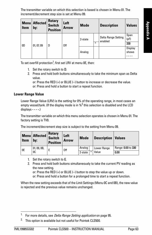
7ML19985GG02 Pointek CLS500 INSTRUCTION MANUAL Page 63
mm
mm
m
Appendix A
The transmitter variable on which this selection is based is chosen in Menu 01. The increment/decrement step size is set at Menu 09.
To set overfill protection1, first set LRV at menu 0E, then:
1. Set the rotary switch to D.2. Press and hold both buttons simultaneously to take the minimum span as Delta
value.or: Press the RED (+) or BLUE () button to increase or decrease the value. or: Press and hold a button to start a repeat function.
Lower Range Value
Lower Range Value (LRV) is the setting for 0% of the operating range, in most cases an empty vessel/tank. (If the display mode is in %2 this selection is disabled and the LCD displays - - - -.)
The transmitter variable on which this menu selection operates is chosen in Menu 01. The factory setting is TV0.
The increment/decrement step size is subject to the setting from Menu 09.
1. Set the rotary switch to E. 2. Press and hold both buttons simultaneously to take the current PV reading as
the new setting. or: Press the RED (+) or BLUE () button to step the value up or down. or: Press and hold a button for a prolonged time to start a repeat function.
When the new setting exceeds that of the Limit Settings (Menu 0C and 0B), the new value is rejected and the previous value remains unchanged.
Menu Item
Affected by:
Rotary Switch Position
Left Arrow Mode Description Values
0D 01, 07, 09 D Off
2-stateDelta Range Setting enabled
Span (pF)
* 330
AnalogDisplay shows - - - -
1. For more details, see Delta Range Setting application on page 95.2. This option is available but not useful for Pointek CLS500.
Menu Item
Affected by:
Rotary Switch Position
Left Arrow Mode Description Values
0E01, 09, 0B, 0C
E OffAnalog Lower Range
Value Range: 0.00 to 330
2-state * 0.00
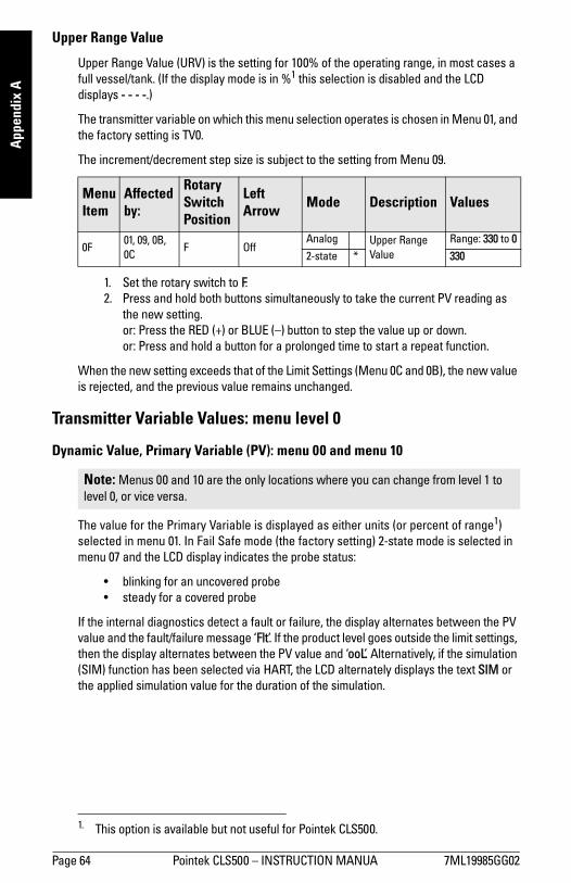
Page 64 Pointek CLS500 INSTRUCTION MANUA 7ML19985GG02
mm
mm
m
App
endi
x A
Upper Range Value
Upper Range Value (URV) is the setting for 100% of the operating range, in most cases a full vessel/tank. (If the display mode is in %1 this selection is disabled and the LCD displays - - - -.)
The transmitter variable on which this menu selection operates is chosen in Menu 01, and the factory setting is TV0.
The increment/decrement step size is subject to the setting from Menu 09.
1. Set the rotary switch to F. 2. Press and hold both buttons simultaneously to take the current PV reading as
the new setting. or: Press the RED (+) or BLUE () button to step the value up or down. or: Press and hold a button for a prolonged time to start a repeat function.
When the new setting exceeds that of the Limit Settings (Menu 0C and 0B), the new value is rejected, and the previous value remains unchanged.
Transmitter Variable Values: menu level 0
Dynamic Value, Primary Variable (PV): menu 00 and menu 10
The value for the Primary Variable is displayed as either units (or percent of range1) selected in menu 01. In Fail Safe mode (the factory setting) 2-state mode is selected in menu 07 and the LCD display indicates the probe status:
blinking for an uncovered probe steady for a covered probe
If the internal diagnostics detect a fault or failure, the display alternates between the PV value and the fault/failure message Flt. If the product level goes outside the limit settings, then the display alternates between the PV value and ooL. Alternatively, if the simulation (SIM) function has been selected via HART, the LCD alternately displays the text SIM or the applied simulation value for the duration of the simulation.
1. This option is available but not useful for Pointek CLS500.
Menu Item
Affected by:
Rotary Switch Position
Left Arrow Mode Description Values
0F01, 09, 0B, 0C
F OffAnalog Upper Range
Value Range: 330 to 0
2-state * 330
Note: Menus 00 and 10 are the only locations where you can change from level 1 to level 0, or vice versa.

7ML19985GG02 Pointek CLS500 INSTRUCTION MANUAL Page 65
mm
mm
m
Appendix A
To change from menu 10 to menu 00:
1. Set the rotary switch to 0.2. Press the RED (+) button for about a second. The LCD briefly displays : M 00
followed by : SEL 0, to indicate that menu 00 is selected. When the button is released the LCD displays the current PV value. No left-arrow is displayed at the top left corner of the LCD in menu 00.
To change from menu 00 to menu 10:
1. Set the rotary switch to 0.2. Press the BLUE button for more than one second. The LCD briefly displays : M 10
followed by : SEL1, to indicate that menu level 1 is selected. Then the LCD displays PV, and a left-arrow is visible in the top left corner of the LCD, indicating menu level 1.
Display the Highest / Lowest Recorded Value
1. Set the rotary switch to 2. The Highest / Lowest recorded values for TV currently selected are displayed alternately.
2. Press the RED (+) button to select the Highest recorded value for display,or: Press the BLUE () button to select the Lowest recorded value for display,
3. Press both buttons simultaneously for more than one second to reset the recorded values back to the dynamic value of this TV. (This will also occur after a reset [power-down] of the device.)
Select the Transmitter Variable (TV) for the Primary Variable (PV).
Menu Item
Affected by:
Rotary Switch Position
Left Arrow Description Values
0001 0
OffDynamic Value (PV)
Units (or % of rangea) selected in menu 0110 On
a. Available but not useful for Pointek CLS500.
Menu Item
Rotary Switch Position
Left Arrow Description
02 2 Off Highest / Lowest Recorded Value
Menu Item
Rotary Switch Position
Left Arrow Description Values
01 1 OffTransmitter Variable selection for PV
0 * TVO (units are pF)
1TV1 (units are user definable
only via HART)
P TV0 (values displayed as %)
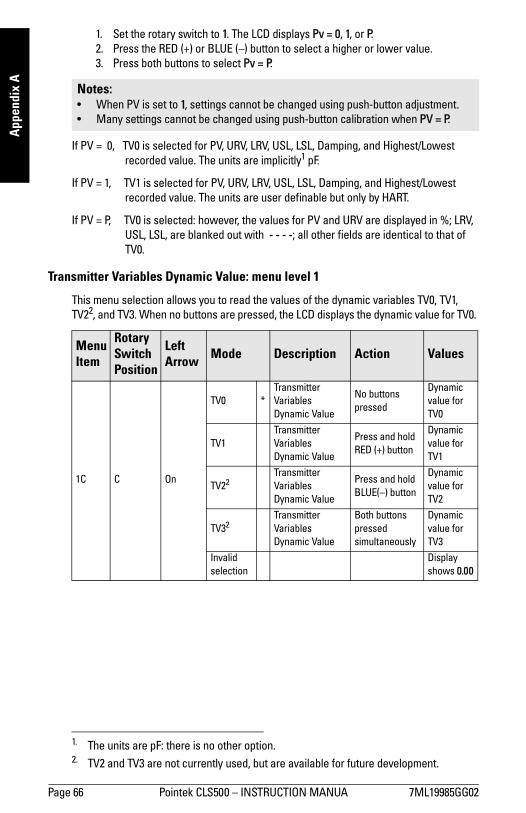
Page 66 Pointek CLS500 INSTRUCTION MANUA 7ML19985GG02
mm
mm
m
App
endi
x A
1. Set the rotary switch to 1. The LCD displays Pv = 0, 1, or P. 2. Press the RED (+) or BLUE () button to select a higher or lower value. 3. Press both buttons to select Pv = P.
If PV = 0, TV0 is selected for PV, URV, LRV, USL, LSL, Damping, and Highest/Lowest recorded value. The units are implicitly1 pF.
If PV = 1, TV1 is selected for PV, URV, LRV, USL, LSL, Damping, and Highest/Lowest recorded value. The units are user definable but only by HART.
If PV = P, TV0 is selected: however, the values for PV and URV are displayed in %; LRV, USL, LSL, are blanked out with - - - -; all other fields are identical to that of TV0.
Transmitter Variables Dynamic Value: menu level 1
This menu selection allows you to read the values of the dynamic variables TV0, TV1, TV22, and TV3. When no buttons are pressed, the LCD displays the dynamic value for TV0.
Notes: When PV is set to 1, settings cannot be changed using push-button adjustment. Many settings cannot be changed using push-button calibration when PV = P.
1. The units are pF: there is no other option.
Menu Item
Rotary Switch Position
Left Arrow Mode Description Action Values
1C C On
TV0 *Transmitter Variables Dynamic Value
No buttons pressed
Dynamic value for TV0
TV1Transmitter Variables Dynamic Value
Press and hold RED (+) button
Dynamic value for TV1
TV22Transmitter Variables Dynamic Value
Press and hold BLUE() button
Dynamic value for TV2
TV32Transmitter Variables Dynamic Value
Both buttons pressed simultaneously
Dynamic value for TV3
Invalid selection
Display shows 0.00
2. TV2 and TV3 are not currently used, but are available for future development.
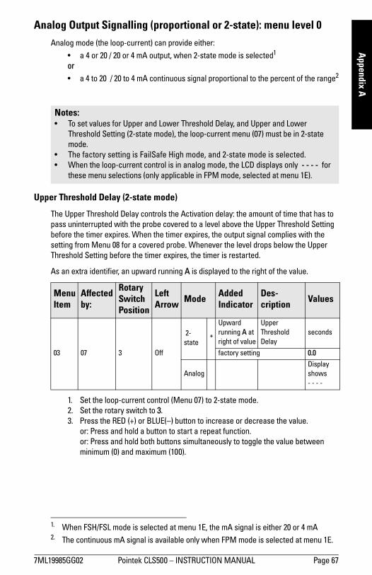
7ML19985GG02 Pointek CLS500 INSTRUCTION MANUAL Page 67
mm
mm
m
Appendix A
Analog Output Signalling (proportional or 2-state): menu level 0Analog mode (the loop-current) can provide either:
a 4 or 20 / 20 or 4 mA output, when 2-state mode is selected1
or
a 4 to 20 / 20 to 4 mA continuous signal proportional to the percent of the range2
Upper Threshold Delay (2-state mode)
The Upper Threshold Delay controls the Activation delay: the amount of time that has to pass uninterrupted with the probe covered to a level above the Upper Threshold Setting before the timer expires. When the timer expires, the output signal complies with the setting from Menu 08 for a covered probe. Whenever the level drops below the Upper Threshold Setting before the timer expires, the timer is restarted.
As an extra identifier, an upward running A is displayed to the right of the value.
1. Set the loop-current control (Menu 07) to 2-state mode.2. Set the rotary switch to 3. 3. Press the RED (+) or BLUE() button to increase or decrease the value.
or: Press and hold a button to start a repeat function.or: Press and hold both buttons simultaneously to toggle the value between minimum (0) and maximum (100).
1. When FSH/FSL mode is selected at menu 1E, the mA signal is either 20 or 4 mA2. The continuous mA signal is available only when FPM mode is selected at menu 1E.
Notes: To set values for Upper and Lower Threshold Delay, and Upper and Lower
Threshold Setting (2-state mode), the loop-current menu (07) must be in 2-state mode.
The factory setting is FailSafe High mode, and 2-state mode is selected. When the loop-current control is in analog mode, the LCD displays only - - - - for
these menu selections (only applicable in FPM mode, selected at menu 1E).
Menu Item
Affected by:
Rotary Switch Position
Left Arrow Mode Added
IndicatorDes-cription Values
03 07 3 Off
2-state
*
Upward running A at right of value
Upper Threshold Delay
seconds
factory setting 0.0
Analog Display shows- - - -
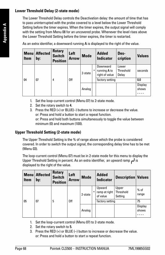
Page 68 Pointek CLS500 INSTRUCTION MANUA 7ML19985GG02
mm
mm
m
App
endi
x A
Lower Threshold Delay (2-state mode)
The Lower Threshold Delay controls the Deactivation delay: the amount of time that has to pass uninterrupted with the probe covered to a level below the Lower Threshold Setting before the timer expires. When the timer expires, the output signal will comply with the setting from Menu 08 for an uncovered probe. Whenever the level rises above the Lower Threshold Setting before the timer expires, the timer is restarted.
As an extra identifier, a downward running A is displayed to the right of the value.
1. Set the loop-current control (Menu 07) to 2-state mode.2. Set the rotary switch to 4. 3. Press the RED (+) or BLUE() buttons to increase or decrease the value.
or: Press and hold a button to start a repeat function.or: Press and hold both buttons simultaneously to toggle the value between minimum (0) and maximum (100).
Upper Threshold Setting (2-state mode)
The Upper Threshold Setting is the % of range above which the probe is considered covered. In order to switch the output signal, the corresponding delay time has to be met (Menu 03).
The loop-current control (Menu 07) must be in 2-state mode for this menu to display the Upper Threshold Setting in percent. As an extra identifier, an upward ramp is displayed to the right of the value.
1. Set the loop-current control (Menu 07) to 2-state mode.2. Set the rotary switch to 5. 3. Press the RED (+) or BLUE () button to increase or decrease the value.
or: Press and hold a button to start a repeat function.
Menu Item
Affected by:
Rotary Switch Position
Left Arrow Mode Added
IndicatorDes-cription Values
04 07 4 Off
2-state *
Downward running A to right of value
Lower Threshold Delay
seconds
factory setting 0.0
Analog Display shows- - - -
Menu Item
Affected by:
Rotary Switch Position
Left Arrow Mode Added
Indicator Description Values
05 07 5 Off
2-state *
Upward ramp at right of value
Upper Threshold Setting
% of range
factory setting 75
Analog Display shows- - - -

7ML19985GG02 Pointek CLS500 INSTRUCTION MANUAL Page 69
mm
mm
m
Appendix A
Lower Threshold Setting (2-state mode)
The Lower Threshold Setting is the % of range below which the probe is considered uncovered. In order to switch the output signal, the corresponding delay time has to be met (Menu 04).
The loop-current control (Menu 07) must be in 2-state mode for this menu to display the Upper Threshold Setting in percent. As an extra identifier, a downward ramp is displayed to the right of the value.
1. Set the loop-current control (Menu 07) to 2-state mode.2. Set the rotary switch to 6. 3. Press the RED (+) or BLUE () button to increase or decrease the value.
or: Press and hold a button to start a repeat function.
Analog Signalling Mode (2-state): menu level 0
The factory setting is for FailSafe High mode1 (selected at menu 1E). When no buttons are pressed, the LCD displays the current mA value. Analog Signalling Mode (a mA reading proportional to level) is not available when FailSafe High or FailSafe Low mode (FSH or FSL) is selected.
2-state Signalling Mode provides a 4 mA or 20 mA output. The settings are relative to a covered probe:
C: Hi selects a 20 mA signal for a covered probe, which switches to 4 mA if the probe becomes uncovered.
C: Lo selects a 4 mA signal for a covered probe, which switches to 20 mA if the probe becomes uncovered.
Menu Item
Affected by:
Rotary Switch Position
Left Arrow Mode Added
Indicator Description Values
06 07 6 Off
2-state *
Downward ramp at right of value
Lower Threshold Setting
% of range
factory setting 25
Analog Display shows- - - -
Note: Menu 08 has precedence over the settings in Menu 07.
1. Pointek CLS500 is most often used in FSH or FSL mode: Free Programming Mode (FPM) can be selected at menu 1E. See page 70 for detailed instructions.

Page 70 Pointek CLS500 INSTRUCTION MANUA 7ML19985GG02
mm
mm
m
App
endi
x A
Menu selections 03, 04, 05, and 06 set the criteria for delay and threshold that have to be met for a change in output signal.
Set the rotary switch to 7. To change the mode to 2-state High, press the RED (+) button for more than one second: the LCD displays C: Hi. When the button is released, the loop-current will switch to 20 mA if the probe is covered, or 4 mA if it is uncovered.
To change the mode to 2-state Low, press the BLUE () button for more than one second: the LCD displays C: Lo. When the button is released, the loop-current will switch to 4 mA, and if the probe is uncovered, or 20 mA if the probe is covered.
While the device is in either FailSafe High or FailSafe Low mode, it reads the loop current as 4 or 20 mA (no faults) or 3.6 or 22 mA (fault situation).
(Analog Mode is only available when Free Programming Mode is selected at menu 1E: in that case it may be restored at any time by pressing both buttons simultaneously for more than one second. The LCD displays C: An while the two buttons are pressed, and displays the current reading when the buttons are released.The loop-current will be between 3.8 and 20.5 mA, and will saturate to one of these values if the level goes beyond the Upper or Lower range settings.)
Menu Item
Affected by:
Rotary Switch Position
Left Arrow Mode Description Action Values
0703, 04, 05, 06, 08
7 Off
Analoga
a. Unavailable when FSH or FSL mode is selected at menu 1E: available only if FPM (Free Programming Mode) is selected.
Signal proportional to % of rangeb
b. This option is available, but not useful for Pointek CLS500.
Press both buttons simultaneously
Display shows C: An
2-state
* 2-state High Press RED (+)Display shows C: Hic
c. While button is pressed, display reads C: Hi. When button is released, display shows 20.00 if the probe is covered, or 4.00 if it is uncovered.
2-state Low Press BLUE ()Display shows C: Lod
d. While button is pressed, display reads C: Lo. When button is released, display shows 4.00 if the probe is covered, or 20.00 if it is uncovered.
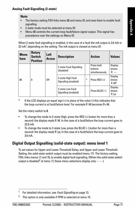
7ML19985GG02 Pointek CLS500 INSTRUCTION MANUAL Page 71
mm
mm
m
Appendix A
Analog Fault Signalling (2-state)
When 2-state fault signalling is enabled, in the case of a fault the mA output is 3.6 mA or 22 mA1, depending on the setting. The mA output is viewed at menu 07.
Set the rotary switch to 8.
To change the mode to 2-state High, press the RED (+) button for more than a second: the display reads F: Hi. In the case of a fault/failure the loop-current goes to 22.0 mA.
To change the mode to 2-state Low, press the BLUE () button for more than a second: the display reads F: Lo. In the case of a fault/failure the loop-current goes to 3.6 mA.
Digital Output Signalling (solid-state output): menu level 1To set values for Upper and Lower Threshold Delay, and Upper and Lower Threshold Setting, the solid-state switch output must be enabled (menu 17). The factory setting, FSH, links menus 17 and 18, to enable digital fault signalling. (When the solid-state switch output is disabled2 at menu 17, these menu selections display only - - - -.)
Note: The factory setting FSH links menu 08 and menu 07, and sets them to enable fault
signalling 2-state mode must be selected at menu 07. Menu 08 controls the current-loop fault/failure signal output. This signal has
precedence over the settings on Menu 07.
Menu Item
Rotary Switch Position
Left Arrow Description Action Values
08 8 Off
2-state Fault Signalling (disabled)
Press both buttons simultaneously
Display shows F: - -
2-state High Fault Signalling (enabled)
* Press RED (+)Display shows F: Hia
a. If the LCD displays an equal sign (=) in place of the colon (:) this indicates that the loop-current is at fault/failure level. For example F: Hi becomes F= Hi.
2-state Low Fault Signalling (enabled)
Press BLUE ()Display shows F: Lo
1. For detailed information, see Fault Signalling on page 13.2. This option is only available if FPM is selected at menu 1E.
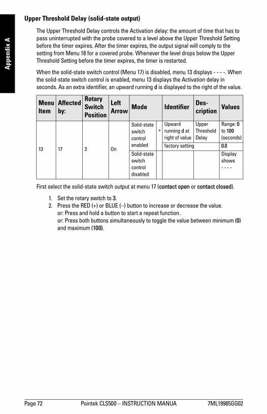
Page 72 Pointek CLS500 INSTRUCTION MANUA 7ML19985GG02
mm
mm
m
App
endi
x A
Upper Threshold Delay (solid-state output)
The Upper Threshold Delay controls the Activation delay: the amount of time that has to pass uninterrupted with the probe covered to a level above the Upper Threshold Setting before the timer expires. After the timer expires, the output signal will comply to the setting from Menu 18 for a covered probe. Whenever the level drops below the Upper Threshold Setting before the timer expires, the timer is restarted.
When the solid-state switch control (Menu 17) is disabled, menu 13 displays - - - -. When the solid-state switch control is enabled, menu 13 displays the Activation delay in seconds. As an extra identifier, an upward running d is displayed to the right of the value.
First select the solid-state switch output at menu 17 (contact open or contact closed).
1. Set the rotary switch to 3. 2. Press the RED (+) or BLUE () button to increase or decrease the value.
or: Press and hold a button to start a repeat function. or: Press both buttons simultaneously to toggle the value between minimum (0) and maximum (100).
Menu Item
Affected by:
Rotary Switch Position
Left Arrow Mode Identifier Des-
cription Values
13 17 3 On
Solid-state switch control enabled
*Upward running d at right of value
Upper Threshold Delay
Range: 0 to 100 (seconds)
factory setting 0.0
Solid-state switch control disabled
Display shows- - - -
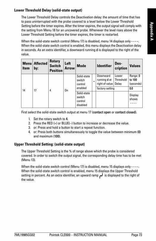
7ML19985GG02 Pointek CLS500 INSTRUCTION MANUAL Page 73
mm
mm
m
Appendix A
Lower Threshold Delay (solid-state output)
The Lower Threshold Delay controls the Deactivation delay: the amount of time that has to pass uninterrupted with the probe covered to a level below the Lower Threshold Setting before the timer expires. After the timer expires, the output signal will comply with the setting from Menu 18 for an uncovered probe. Whenever the level rises above the Lower Threshold Setting before the timer expires, the timer is restarted.
When the solid-state switch control (Menu 17) is disabled, menu 14 displays only - - - -. When the solid-state switch control is enabled, this menu displays the Deactivation delay in seconds. As an extra identifier, a downward running d is displayed to the right of the value.
First select the solid-state switch output at menu 17 (contact open or contact closed).
1. Set the rotary switch to 4. 2. Press the RED (+) or BLUE() button to increase or decrease the value. 3. or: Press and hold a button to start a repeat function. 4. or: Press both buttons simultaneously to toggle the value between minimum (0)
and maximum (100).
Upper Threshold Setting: (solid-state output)
The Upper Threshold Setting is the % of range above which the probe is considered covered. In order to switch the output signal, the corresponding delay time has to be met (Menu 13).
When the solid-state switch control (Menu 17) is disabled, menu 15 displays only - - - -. When the solid-state switch control is enabled, menu 15 displays the Upper Threshold setting in percent. As an extra identifier, an upward ramp is displayed to the right of the value.
Menu Item
Affected by:
Rotary Switch Position
Left Arrow Mode Identifier Des-
cription Values
14 17 4 On
Solid-state switch control enabled
*
Downward running d at right of value
Lower Threshold Delay
Range: 0 to 100 (seconds)
factory setting 0.0
Solid-state switch control disabled
Display shows - - - -
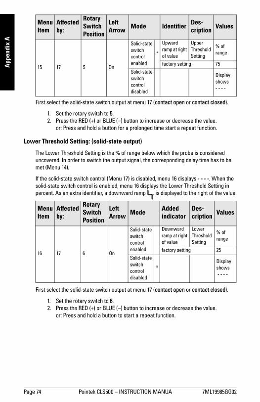
Page 74 Pointek CLS500 INSTRUCTION MANUA 7ML19985GG02
mm
mm
m
App
endi
x A
First select the solid-state switch output at menu 17 (contact open or contact closed).
1. Set the rotary switch to 5. 2. Press the RED (+) or BLUE () button to increase or decrease the value.
or: Press and hold a button for a prolonged time start a repeat function.
Lower Threshold Setting: (solid-state output)
The Lower Threshold Setting is the % of range below which the probe is considered uncovered. In order to switch the output signal, the corresponding delay time has to be met (Menu 14).
If the solid-state switch control (Menu 17) is disabled, menu 16 displays - - - -. When the solid-state switch control is enabled, menu 16 displays the Lower Threshold Setting in percent. As an extra identifier, a downward ramp . is displayed to the right of the value.
First select the solid-state switch output at menu 17 (contact open or contact closed).
1. Set the rotary switch to 6. 2. Press the RED (+) or BLUE () button to increase or decrease the value.
or: Press and hold a button to start a repeat function.
Menu Item
Affected by:
Rotary Switch Position
Left Arrow Mode Identifier Des-
cription Values
15 17 5 On
Solid-state switch control enabled
*
Upward ramp at right of value
Upper Threshold Setting
% of range
factory setting 75
Solid-state switch control disabled
Display shows- - - -
Menu Item
Affected by:
Rotary Switch Position
Left Arrow Mode Added
indicatorDes-cription Values
16 17 6 On
Solid-state switch control enabled
Downward ramp at right of value
Lower Threshold Setting
% of range
factory setting 25
Solid-state switch control disabled
*Display shows - - - -

7ML19985GG02 Pointek CLS500 INSTRUCTION MANUAL Page 75
mm
mm
m
Appendix A
Digital Signalling Mode (solid-state output)
Controls the solid-state switch response to level settings, and allows you to set the switch to contact open or contact closed. The settings are relative to a covered probe, and the criteria are set in Upper and Lower Threshold settings (see pages 73 and 74,. menus 15 and 16). With contact closed, the switch is on: with contact open the switch is off.
While a button is pressed, the LCD displays S: cc1 (contact closed) or S: co (contact open). When the button is released an equal sign (=) indicating status replaces the colon, and the reading depends on the status of the probe2.
Example: S = cc is selected (contact closed with a covered probe) If the probe is uncovered when the button is released, the display changes from
S: cc to S = co. If the probe is covered when the buttons are released, the display changes to
S = cc. If you press either button briefly, the LCD displays the current setting, in this
case, S: cc.
Notes: Factory setting FSH links menus 17 and 18, and sets them to enable digital fault
signalling. (In Free Programming Mode, available at menu 1E, all menu items are independent.)
Menu 18 has precedence over menu 17.
1. A colon at the extreme left of the display appears while the button is pressed to indicate when a setting is accepted, for example : S: cc.
2. If digital fault signalling is enabled at menu 18, it takes precedence, and no equal sign will appear in the display for menu 17 if the device is responding to a fault.
Menu Item
Affected by:
Rotary Switch Position
Left Arrow Mode Des-
cription Action Values
17 18 7 OnDigital Signalling Mode
*Contact Closed: switch on
Press and hold RED (+) button
Display showsa
S: cc
a. While the button is pressed: when released the display depends on the probe status.
Contact Open: switch off
Press and hold BLUE () button
Display showsa
S: co
Digital Signalling Mode disabledb
b. This option is only available when Free Programming Mode is selected at menu 1E.
Press and hold both buttons
Display shows S: - -

Page 76 Pointek CLS500 INSTRUCTION MANUA 7ML19985GG02
mm
mm
m
App
endi
x A
1. Set the rotary switch to 7. 2. Press and hold the RED (+) or BLUE () button to select contact open or contact
closed,3. If required, adjust menu selections 13, 14, 15 and 16 which set the criteria and
threshold that have to be met for a change in output signal.(In Free Programming Mode only, press and hold both buttons to disable Digital Signalling Mode.)
Digital Fault Signalling
Controls the solid-state switch response to a fault/failure and allows you to select either FailSafe High (FSH), or FailSafe Low (FSL).
In FailSafe High mode in normal conditions, the switch is on and contact closed, as long as the conditions do not cause the switch to close in response to settings at menu 17. If a fault is detected the switch will be off and contact open. This setting provides no current in a fault situation, and high current (20 mA) in normal conditions
In FailSafe Low mode in normal conditions, the switch is off and contact open, as long as the conditions do not cause the switch to close in response to settings at menu 17. If a fault is detected the switch will be on and contact closed. This setting provides high current (20 mA) in a fault situation, and no current in normal conditions.
Notes: Factory setting FSH links menus 17 and 18, and sets them to enable digital fault
signalling. (In Free Programming Mode, available at menu 1E, all menu items are independent.)
Menu 18 has precedence over the settings on Menu 17, but if no fault exists, the switch will respond to the setting in menu 17.
FailSafe HIgh FailSafe Lowno fault fault no fault fault
uncovered covered uncovered covered uncovered covered uncovered covered
20 mAclosed
4 mAopen
3.6 mAopen
4 mAopen
20 mAclosed
22 mAclosed
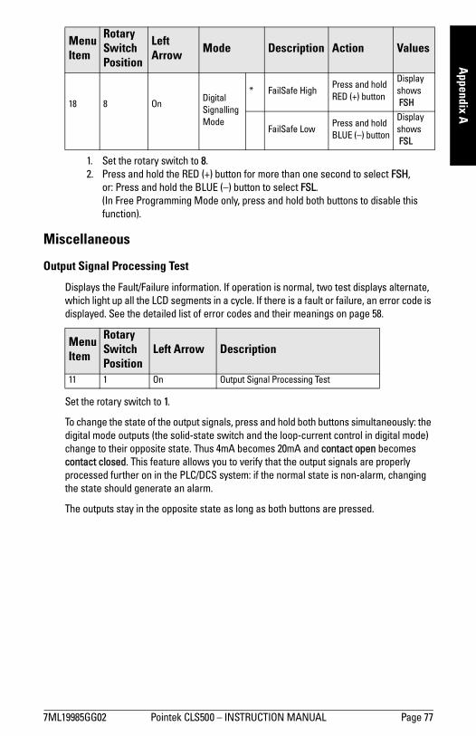
7ML19985GG02 Pointek CLS500 INSTRUCTION MANUAL Page 77
mm
mm
m
Appendix A
1. Set the rotary switch to 8. 2. Press and hold the RED (+) button for more than one second to select FSH,
or: Press and hold the BLUE () button to select FSL. (In Free Programming Mode only, press and hold both buttons to disable this function).
Miscellaneous
Output Signal Processing Test
Displays the Fault/Failure information. If operation is normal, two test displays alternate, which light up all the LCD segments in a cycle. If there is a fault or failure, an error code is displayed. See the detailed list of error codes and their meanings on page 58.
Set the rotary switch to 1.
To change the state of the output signals, press and hold both buttons simultaneously: the digital mode outputs (the solid-state switch and the loop-current control in digital mode) change to their opposite state. Thus 4mA becomes 20mA and contact open becomes contact closed. This feature allows you to verify that the output signals are properly processed further on in the PLC/DCS system: if the normal state is non-alarm, changing the state should generate an alarm.
The outputs stay in the opposite state as long as both buttons are pressed.
Menu Item
Rotary Switch Position
Left Arrow Mode Description Action Values
18 8 OnDigital Signalling Mode
* FailSafe HighPress and hold RED (+) button
Display shows FSH
FailSafe LowPress and hold BLUE () button
Display shows FSL
Menu Item
Rotary Switch Position
Left Arrow Description
11 1 On Output Signal Processing Test

Page 78 Pointek CLS500 INSTRUCTION MANUA 7ML19985GG02
mm
mm
m
App
endi
x A
Factory Settings
Displays whether the factory settings are still in place, or how much they have been changed, and allows you to restore the factory settings.
Set the rotary switch to 2. To restore the factory settings, press both buttons simultaneously to change the LCD to do it and hold both buttons for more than one second. When the buttons are released, the LCD displays FAC A.
Range Inversion
Displays whether the device is operating with a normal or inverted range setting. A normal range setting is where LRV (Menu 0E) is lower in value than URV (Menu 0F): the LCD displays nor. An inverted range is where LRV (Menu 0E) is higher in value than URV (Menu 0F): the LCD displays inv.
1. Set the rotary switch to 9. 2. Press both buttons simultaneously for more than one second to toggle between
the two modes, effectively switching the values for LRV and URV.
Menu Item
Rotary Switch Position
Left Arrow Description LCD Display Meaning
12 2 On
Factory Settings FAC ANo parameters changed from factory setting
FAC PRange settings altered: timers and thresholds unchanged
FAC ?More parameters have been changed
Menu Item
Rotary Switch Position
Left Arrow Description Mode Values
19 9 On Range Inversionnormal * Display shows nor
inverted Display shows inv
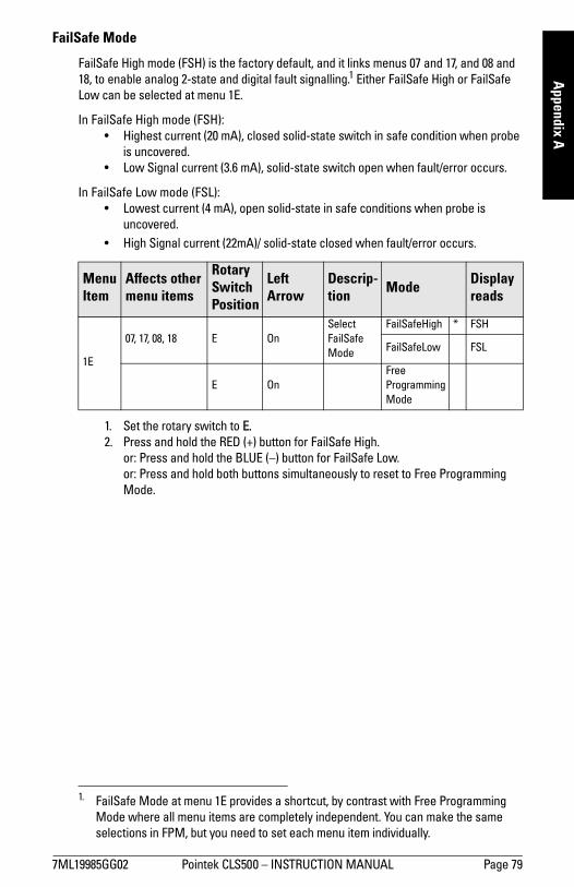
7ML19985GG02 Pointek CLS500 INSTRUCTION MANUAL Page 79
mm
mm
m
Appendix A
FailSafe Mode
FailSafe High mode (FSH) is the factory default, and it links menus 07 and 17, and 08 and 18, to enable analog 2-state and digital fault signalling.1 Either FailSafe High or FailSafe Low can be selected at menu 1E.
In FailSafe High mode (FSH): Highest current (20 mA), closed solid-state switch in safe condition when probe
is uncovered. Low Signal current (3.6 mA), solid-state switch open when fault/error occurs.
In FailSafe Low mode (FSL): Lowest current (4 mA), open solid-state in safe conditions when probe is
uncovered. High Signal current (22mA)/ solid-state closed when fault/error occurs.
1. Set the rotary switch to E. 2. Press and hold the RED (+) button for FailSafe High.
or: Press and hold the BLUE () button for FailSafe Low.or: Press and hold both buttons simultaneously to reset to Free Programming Mode.
1. FailSafe Mode at menu 1E provides a shortcut, by contrast with Free Programming Mode where all menu items are completely independent. You can make the same selections in FPM, but you need to set each menu item individually.
Menu Item
Affects other menu items
Rotary Switch Position
Left Arrow
Descrip-tion Mode Display
reads
1E
07, 17, 08, 18 E OnSelect FailSafe Mode
FailSafeHigh * FSH
FailSafeLow FSL
E OnFree Programming Mode
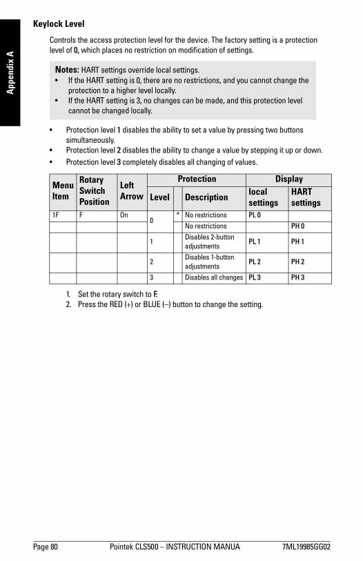
Page 80 Pointek CLS500 INSTRUCTION MANUA 7ML19985GG02
mm
mm
m
App
endi
x A
Keylock Level
Controls the access protection level for the device. The factory setting is a protection level of 0, which places no restriction on modification of settings.
Protection level 1 disables the ability to set a value by pressing two buttons simultaneously.
Protection level 2 disables the ability to change a value by stepping it up or down. Protection level 3 completely disables all changing of values.
1. Set the rotary switch to F. 2. Press the RED (+) or BLUE () button to change the setting.
Notes: HART settings override local settings. If the HART setting is 0, there are no restrictions, and you cannot change the
protection to a higher level locally. If the HART setting is 3, no changes can be made, and this protection level
cannot be changed locally.
Menu Item
Rotary Switch Position
Left Arrow
Protection Display
Level Description local settings
HART settings
1F F On0
* No restrictions PL 0
No restrictions PH 0
1Disables 2-button adjustments
PL 1 PH 1
2Disables 1-button adjustments
PL 2 PH 2
3 Disables all changes PL 3 PH 3
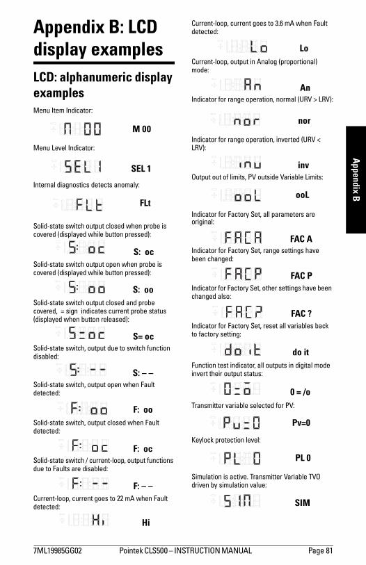
7ML19985GG02 Pointek CLS500 INSTRUCTION MANUAL Page 81
mm
mm
m
Appendix B
Appendix B: LCD display examplesLCD: alphanumeric display examplesMenu Item Indicator:
Menu Level Indicator:
Internal diagnostics detects anomaly:
Solid-state switch output closed when probe is covered (displayed while button pressed):
Solid-state switch output open when probe is covered (displayed while button pressed):
Solid-state switch output closed and probe covered, = sign indicates current probe status (displayed when button released):
Solid-state switch, output due to switch function disabled:
Solid-state switch, output open when Fault detected:
Solid-state switch, output closed when Fault detected:
Solid-state switch / current-loop, output functions due to Faults are disabled:
Current-loop, current goes to 22 mA when Fault detected:
Current-loop, current goes to 3.6 mA when Fault detected:
Current-loop, output in Analog (proportional) mode:
Indicator for range operation, normal (URV > LRV):
Indicator for range operation, inverted (URV < LRV):
Output out of limits, PV outside Variable Limits:
Indicator for Factory Set, all parameters are original:
Indicator for Factory Set, range settings have been changed:
Indicator for Factory Set, other settings have been changed also:
Indicator for Factory Set, reset all variables back to factory setting:
Function test indicator, all outputs in digital mode invert their output status:
Transmitter variable selected for PV:
Keylock protection level:
Simulation is active. Transmitter Variable TVO driven by simulation value:
M 00
SEL 1
FLt
S: oc
S: oo
S= oc
S: – –
F: oo
F: oc
F: – –
Hi
Lo
An
nor
inv
ooL
FAC A
FAC P
FAC ?
do it
0 = /o
Pv=0
PL 0
SIM
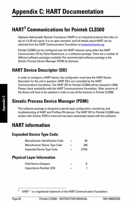
Page 82 Pointek CLS500 INSTRUCTION MANUAL 7ML19985GG02
mm
mm
m
App
endi
x C
Appendix C: HART Documentation
HART1 Communications for Pointek CLS500Highway Addressable Remote Transducer (HART) is an industrial protocol that rides on top of a 4-20 mA signal. It is an open standard, and full details about HART can be obtained from the HART Communication Foundation at www.hartcomm.org
Pointek CLS500 can be configured over the HART network using either the HART Communicator 275 by Fisher-Rosemount, or a software package. There are a number of different software packages available.The recommended software package is the Simatic Process Device Manager (PDM) by Siemens.
HART Device Descriptor (DD) In order to configure a HART device, the configurator must have the HART Device Descriptor for the unit in question. HART DDs are controlled by the HART Communications Foundation. The HART DD for Pointek CLS500 will be released in 2003. Please check availability with the HART Communications Foundation. Older versions of the library will have to be updated in order to use all the features in Pointek CLS500.
Simatic Process Device Manager (PDM):This software package is designed to permit easy configuration, monitoring, and troubleshooting of HART and Profibus PA devices. The HART DD for Pointek CLS500 was written with Simatic PDM in mind and has been extensively tested with this software.
HART information
Expanded Device Type Code:
Physical Layer Information
1. HART® is a registered trademark of the HART Communication Foundation.
Manufacturer Identification Code = 84Manufacturer Device Type Code = 248Expanded Device Type Code = 21752
Field Device Category = ACapacitance Number (CN) = 1
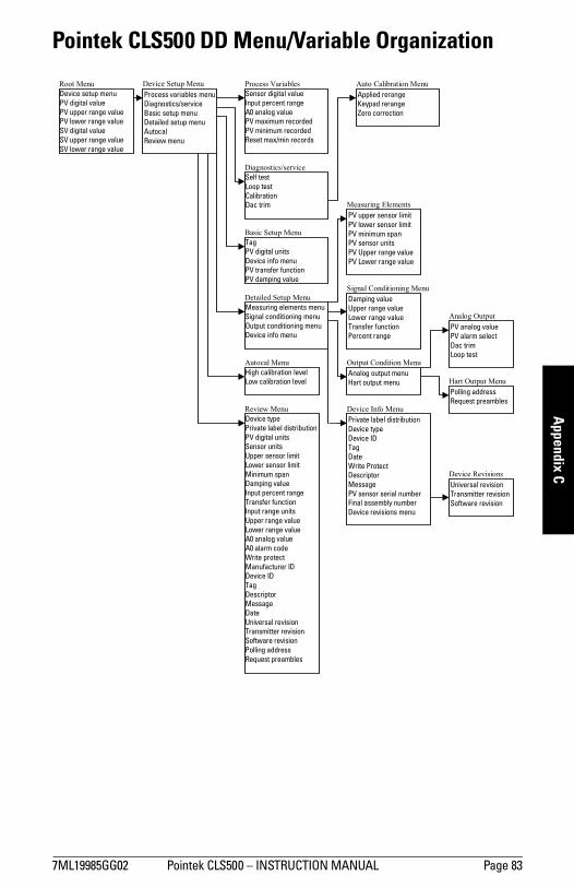
7ML19985GG02 Pointek CLS500 INSTRUCTION MANUAL Page 83
mm
mm
m
Appendix C
Pointek CLS500 DD Menu/Variable Organization
Device setup menu PV digital value PV upper range value PV lower range value SV digital value SV upper range value SV lower range value
Process variables menuDiagnostics/service Basic setup menu Detailed setup menu Autocal Review menu
Sensor digital valueInput percent range A0 analog value PV maximum recorded PV minimum recorded Reset max/min records
Self testLoop test Calibration Dac trim
TagPV digital units Device info menu PV transfer function PV damping value
Device typePrivate label distributionPV digital units Sensor units Upper sensor limit Lower sensor limit Minimum span Damping value Input percent range Transfer function Input range units Upper range value Lower range value A0 analog value A0 alarm code Write protect Manufacturer ID Device ID Tag Descriptor Message Date Universal revision Transmitter revision Software revision Polling address Request preambles
High calibration levelLow calibration level
Applied rerangeKeypad rerange Zero correction
Measuring elements menuSignal conditioning menu Output conditioning menu Device info menu
PV upper sensor limitPV lower sensor limit PV minimum span PV sensor units PV Upper range value PV Lower range value
Damping valueUpper range value Lower range value Transfer function Percent range
Analog output menuHart output menu
Private label distributionDevice type Device ID Tag Date Write Protect Descriptor Message PV sensor serial number Final assembly number Device revisions menu
PV analog value PV alarm select Dac trim Loop test
Polling address Request preambles
Universal revision Transmitter revision Software revision
Root Menu Device Setup Menu Process Variables
Diagnostics/service
Basic Setup Menu
Detailed Setup Menu
Autocal Menu
Review Menu Device Info Menu
Output Condition Menu
Signal Conditioning Menu
Measuring Elements
Auto Calibration Menu
Analog Output
Hart Output Menu
Device Revisions
Page 84 Pointek CLS500 INSTRUCTION MANUAL 7ML19985GG02
mm
mm
m
App
endi
x C
HART Response Code InformationAdditional response code information, Second Byte.
Bit #7: Field Device MalfunctionWhen the transmitter detects a malfunction, the Analog Output will be set in a fault state.
Bit #6: Configuration ChangedWhen any of the settings in EEROM is changed either by a write command or by manual ZERO or SPAN adjust, this bit is set. Use command 38 to reset.
Bit #5: Cold StartThis bit is issued once after an initialisation cycle is complete; this can occur after a power loss or as a result of a (watchdog) reset.
Bit #4: Extended Status AvailableWhen any of the extended status bits is set this flag is raised. Use command 48 to get detailed status information.
Bit #3: Output Current FixedThis bit is set as long as the Primary Variable Analog Output is set to a fixed value.
Bit #2: Primary Variable Analog Output SaturatedFlag is set when the Primary Analog Output saturates below 3.8 mA and above 20.5 mA.
Bit #0: Primary Variable Out of LimitsThis flag is set whenever the Transmitter Variable #0 (in pF), the Primary Variable exceeds the Sensor Limits returned with Command 14, Read Primary Variable Sensor Limits.
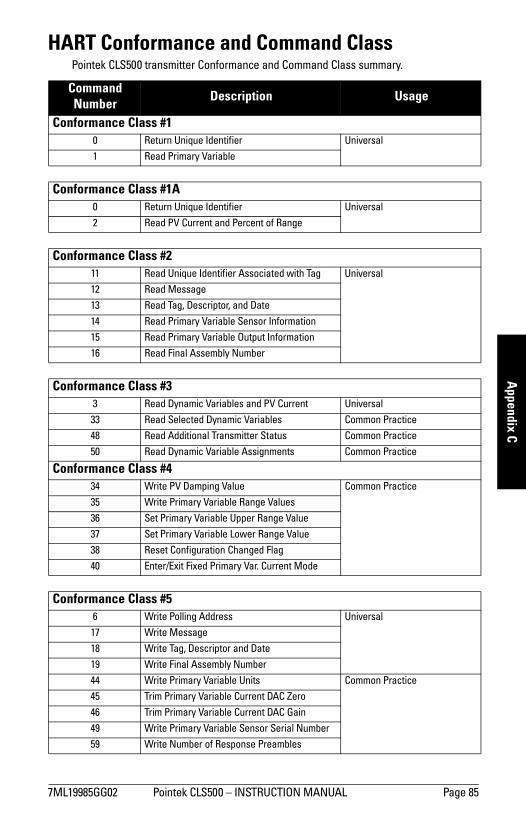
7ML19985GG02 Pointek CLS500 INSTRUCTION MANUAL Page 85
mm
mm
m
Appendix C
HART Conformance and Command ClassPointek CLS500 transmitter Conformance and Command Class summary.
Command Number Description Usage
Conformance Class #10 Return Unique Identifier Universal
1 Read Primary Variable
Conformance Class #1A0 Return Unique Identifier Universal
2 Read PV Current and Percent of Range
Conformance Class #211 Read Unique Identifier Associated with Tag Universal
12 Read Message
13 Read Tag, Descriptor, and Date
14 Read Primary Variable Sensor Information
15 Read Primary Variable Output Information
16 Read Final Assembly Number
Conformance Class #33 Read Dynamic Variables and PV Current Universal
33 Read Selected Dynamic Variables Common Practice
48 Read Additional Transmitter Status Common Practice
50 Read Dynamic Variable Assignments Common Practice
Conformance Class #434 Write PV Damping Value Common Practice
35 Write Primary Variable Range Values
36 Set Primary Variable Upper Range Value
37 Set Primary Variable Lower Range Value
38 Reset Configuration Changed Flag
40 Enter/Exit Fixed Primary Var. Current Mode
Conformance Class #56 Write Polling Address Universal
17 Write Message
18 Write Tag, Descriptor and Date
19 Write Final Assembly Number
44 Write Primary Variable Units Common Practice
45 Trim Primary Variable Current DAC Zero
46 Trim Primary Variable Current DAC Gain
49 Write Primary Variable Sensor Serial Number
59 Write Number of Response Preambles
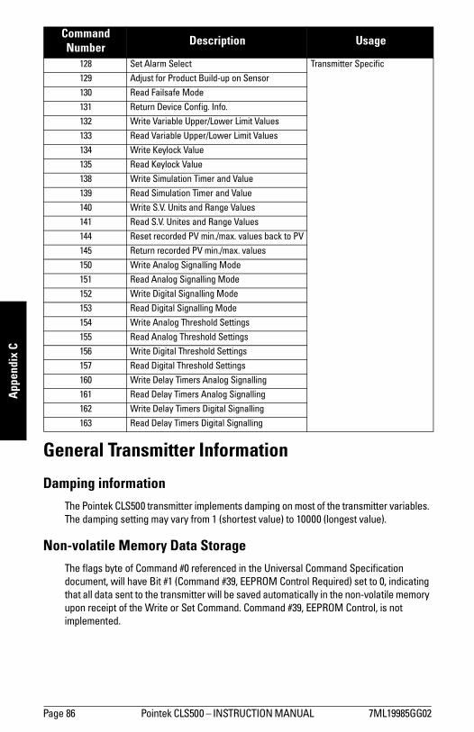
Page 86 Pointek CLS500 INSTRUCTION MANUAL 7ML19985GG02
mm
mm
m
App
endi
x C
General Transmitter Information
Damping informationThe Pointek CLS500 transmitter implements damping on most of the transmitter variables. The damping setting may vary from 1 (shortest value) to 10000 (longest value).
Non-volatile Memory Data StorageThe flags byte of Command #0 referenced in the Universal Command Specification document, will have Bit #1 (Command #39, EEPROM Control Required) set to 0, indicating that all data sent to the transmitter will be saved automatically in the non-volatile memory upon receipt of the Write or Set Command. Command #39, EEPROM Control, is not implemented.
128 Set Alarm Select Transmitter Specific
129 Adjust for Product Build-up on Sensor
130 Read Failsafe Mode
131 Return Device Config. Info.
132 Write Variable Upper/Lower Limit Values
133 Read Variable Upper/Lower Limit Values
134 Write Keylock Value
135 Read Keylock Value
138 Write Simulation Timer and Value
139 Read Simulation Timer and Value
140 Write S.V. Units and Range Values
141 Read S.V. Unites and Range Values
144 Reset recorded PV min./max. values back to PV
145 Return recorded PV min./max. values
150 Write Analog Signalling Mode
151 Read Analog Signalling Mode
152 Write Digital Signalling Mode
153 Read Digital Signalling Mode
154 Write Analog Threshold Settings
155 Read Analog Threshold Settings
156 Write Digital Threshold Settings
157 Read Digital Threshold Settings
160 Write Delay Timers Analog Signalling
161 Read Delay Timers Analog Signalling
162 Write Delay Timers Digital Signalling
163 Read Delay Timers Digital Signalling
Command Number Description Usage

7ML19985GG02 Pointek CLS500 INSTRUCTION MANUAL Page 87
mm
mm
m
Appendix C
MultiDrop operationPointek CLS500 transmitter supports MultiDrop Operation.
Burst modePointek CLS500 transmitter does not support Burst Mode.
Units conversionsThe Transmitter Variable #0 Units are in pF and cannot be changed.
The Transmitter Variable #1 Values may be set to any Units and Value with Command #140. The Transmitter Variable Range Values may be read at any time with Command #141.
The value returned as Secondary Variable (S.V.) is the result of the following calculation:
TV1 = TV0 Dynamic Range Value in percent x (TV#1URV TV#1LRV) + TV#1LRV.
This method provides a means of converting TV#0 which is always in pF, to alternative units (level or volume).
Additional Universal Command SpecificationsFor a document listing the additional Universal Command Specifications, please contact Technical Publications at [email protected].
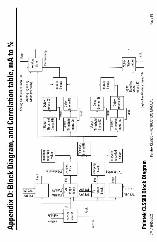
7ML1
9985
GG02
Poin
tek
CLS5
00
INST
RUCT
ION
MAN
UAL
Page
88
App
endi
x D
: Blo
ck D
iagr
am, a
nd C
orre
latio
n ta
ble,
mA
to %
sens
or
circ
uit
TV0
rang
e bl
ock
dam
ping
bl
ock
TV s
elec
t (m
enu
01)
max
/min
re
cord
ed
valu
e
stat
us
2-st
ate
TV1
rang
e bl
ock
dam
ping
bl
ock
max
/min
re
cord
ed
valu
e
Uppe
r Th
resh
old
(men
u 05
)
Uppe
r Th
resh
old
(men
u15)
Dela
y (m
enu
03)
Low
er
Thre
shol
d (m
enu
06)
Low
er
Thre
shol
d (m
enu
16)
Dela
y (m
enu
04)
Dela
y (m
enu
13)
Dela
y (m
enu
14)
stat
us
2-st
ate
Digi
tal
Sign
allin
g M
ode
(men
u 17
)
Solid
-St
ate
Outp
ut
Anal
og
Sign
al
Anal
og F
ault/
Failu
re (m
enu
08)
Curr
ent-l
oop
Faul
t
sens
or
pFTV
0Faul
t
TV1
Faul
t
Faul
t
rese
t
rese
t
rese
t
rese
t
TV0 USL
TV0 LSLTV0 URV
TV0 LRVTV1 URV
TV1 LRV
TV1 USL
TV1 LSL
TV1 dampingTV0 damping
Poin
tek
CLS5
00 B
lock
Dia
gram
Digi
tal F
ault/
Failu
re (m
enu
18)
Faul
tcal low
cal highAn
alog
Sig
nalli
ng
Mod
e (m
enu
07)
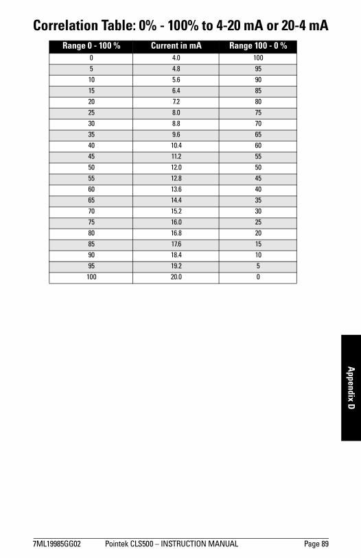
7ML19985GG02 Pointek CLS500 INSTRUCTION MANUAL Page 89
mm
mm
m
Appendix D
Correlation Table: 0% - 100% to 4-20 mA or 20-4 mARange 0 - 100 % Current in mA Range 100 - 0 %
0 4.0 100
5 4.8 95
10 5.6 90
15 6.4 85
20 7.2 80
25 8.0 75
30 8.8 70
35 9.6 65
40 10.4 60
45 11.2 55
50 12.0 50
55 12.8 45
60 13.6 40
65 14.4 35
70 15.2 30
75 16.0 25
80 16.8 20
85 17.6 15
90 18.4 10
95 19.2 5
100 20.0 0

Page 90 Pointek CLS500 INSTRUCTION MANUAL 7ML19985GG02
mm
mm
m
App
endi
x E
Appendix E: Pointek CLS500, dimensions and application examples
Standard rod version
1) Minimum Y02 (active shield length) = 50 mm (1.96)
Threaded Flanged
ø16 mm(0.63)
inactive tip
PFAinsulated
probe
transmitter/electronics
20 mm(0.79)
Y02
30m
m (1
.18)
Y01
(inse
rtio
n le
ngth
)m
in. =
200
mm
(7.8
7) m
ax. =
100
0m
m (3
9.37
)
mea
surin
g le
ngth
transmitter/electronics
Y021)
30m
m (1
.18)
Y01
(inse
rtio
n le
ngth
)m
in. =
200
mm
(7.8
7) m
ax. =
100
0m
m (3
9.37
)
PFAinsulated
probe
inactive tip
ø16 mm(0.63)
mea
surin
g le
ngth
1)

7ML19985GG02 Pointek CLS500 INSTRUCTION MANUAL Page 91
mm
mm
m
Appendix E
High temperature rod version
1) Non conductive materials only2) Minimum Y02 (active shield length) = 105 mm (4.13)3) Minimum Y02 (active shield length) = 100 mm (3.94)
Single piece flange (7ML5604)Stainless steel rod1)
Single piece flange (7ML5604)Enamel rod
Flange Facing (raised face)
Flange Class Facing thickness
ASME 150/300 2 mm (0.08)
ASME 600/900 7 mm (0.28)
PN16/25/40/64 2 mm (0.08)
thermalisolator
enamelprobe
40 mm(1.57)
Y022)
mea
surin
g le
ngth
2)
Y01
(inse
rtio
n le
ngth
)m
in. =
200
mm
(7.8
7) m
ax. =
100
0m
m (3
9.37
)
ø16 mm(0.63)
thermalisolator
stainlesssteel probe
Y023)
mea
surin
g le
ngth
3)
Y01
(inse
rtio
n le
ngth
)m
in. =
200
mm
(7.8
7) m
ax. =
100
0m
m (3
9.37
)
ø19 mm(0.75)
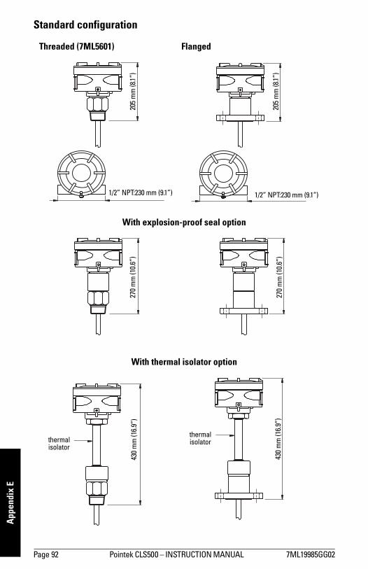
Page 92 Pointek CLS500 INSTRUCTION MANUAL 7ML19985GG02
mm
mm
m
App
endi
x E
Standard configuration
Threaded (7ML5601) Flanged
With explosion-proof seal option
With thermal isolator option
205
mm
(8.1
)
1/2 NPT:230 mm (9.1) 1/2 NPT:230 mm (9.1)
205
mm
(8.1
)
270
mm
(10.
6)
270
mm
(10.
6)
430
mm
(16.
9)
thermalisolator
430
mm
(16.
9)
thermalisolator
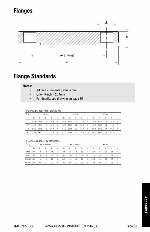
7ML19985GG02 Pointek CLS500 INSTRUCTION MANUAL Page 93
mm
mm
m
Appendix E
Flanges
Flange StandardsNotes:
All measurements given in mm One (1) inch = 25.4mm For details, see drawing on page 90.
øL
b
øK (n holes)
øD
23
18
18
18
PN 10 (PN 16)
FLANGES acc. DIN standards
165
200
220
285
NW50
D
160
180
240
125
k L Dk
8
8
8
4
n
20
20
22
18
b D bL n nL
PN 64
k b
PN 25 (PN 40)
NW80
NW150
NW100
165
300
235
200
20125 18
27
23
18
250
190
160
24
28
24
4
8
8
8 23
27
33
23135180
345
250
215
280
200
170
426
36
30
28
8
8
8
FLANGES acc. ANSI standards150lbs 300lbs 600lbs
D k bL n D k L b n D k L b n
2"
3"
6"
4"
152.4
190.5
228.6
279.4 22
19
19
19120.6
152.4
241.3
190.5
8
8
4
4
25.4
23.8
23.8
19.0
22
22
22
19165.1
209.6
254.0
317.5
168.3
200.0
269.9
127.0
12
8
8
8
28.6
31.8
36.5
22.2 127.0
292.1
215.9
168.3
355.6
273.1
209.6
165.1 25.4
47.6
38.1
31.822
26
29
19
8
8
12
8
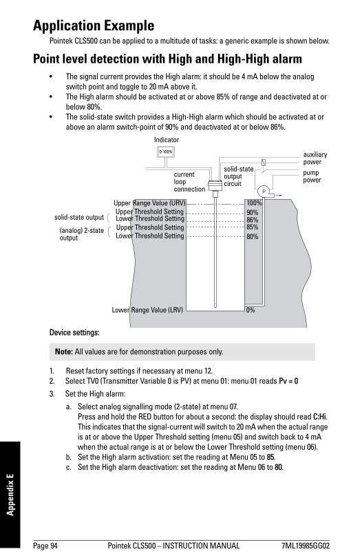
Page 94 Pointek CLS500 INSTRUCTION MANUAL 7ML19985GG02
mm
mm
m
App
endi
x E
Application ExamplePointek CLS500 can be applied to a multitude of tasks: a generic example is shown below.
Point level detection with High and High-High alarm The signal current provides the High alarm: it should be 4 mA below the analog
switch point and toggle to 20 mA above it. The High alarm should be activated at or above 85% of range and deactivated at or
below 80%. The solid-state switch provides a High-High alarm which should be activated at or
above an alarm switch-point of 90% and deactivated at or below 86%.
Device settings:
1. Reset factory settings if necessary at menu 12.2. Select TV0 (Transmitter Variable 0 is PV) at menu 01: menu 01 reads Pv = 0
3. Set the High alarm:
a. Select analog signalling mode (2-state) at menu 07. Press and hold the RED button for about a second: the display should read C:Hi. This indicates that the signal-current will switch to 20 mA when the actual range is at or above the Upper Threshold setting (menu 05) and switch back to 4 mA when the actual range is at or below the Lower Threshold setting (menu 06).
b. Set the High alarm activation: set the reading at Menu 05 to 85.c. Set the High alarm deactivation: set the reading at Menu 06 to 80.
Note: All values are for demonstration purposes only.
P
Indicator
0-100% auxiliary powerpump power
solid-state output circuit
current loop connection
100%90%
80%
0%
85%86%
Upper Threshold SettingLower Threshold SettingUpper Threshold Setting
Lower Threshold Setting
Upper Range Value (URV)
Lower Range Value (LRV)
solid-state output
(analog) 2-state output
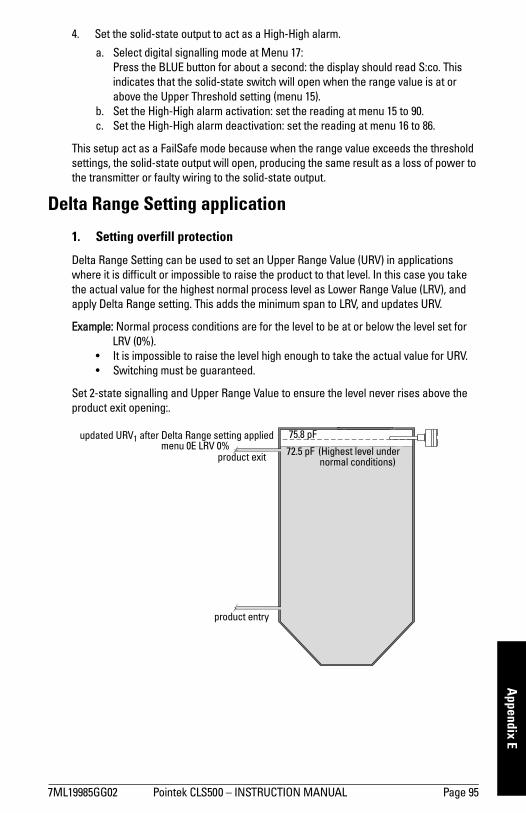
7ML19985GG02 Pointek CLS500 INSTRUCTION MANUAL Page 95
mm
mm
m
Appendix E
4. Set the solid-state output to act as a High-High alarm.
a. Select digital signalling mode at Menu 17:Press the BLUE button for about a second: the display should read S:co. This indicates that the solid-state switch will open when the range value is at or above the Upper Threshold setting (menu 15).
b. Set the High-High alarm activation: set the reading at menu 15 to 90.c. Set the High-High alarm deactivation: set the reading at menu 16 to 86.
This setup act as a FailSafe mode because when the range value exceeds the threshold settings, the solid-state output will open, producing the same result as a loss of power to the transmitter or faulty wiring to the solid-state output.
Delta Range Setting application
1. Setting overfill protection
Delta Range Setting can be used to set an Upper Range Value (URV) in applications where it is difficult or impossible to raise the product to that level. In this case you take the actual value for the highest normal process level as Lower Range Value (LRV), and apply Delta Range setting. This adds the minimum span to LRV, and updates URV.
Example: Normal process conditions are for the level to be at or below the level set for LRV (0%).
It is impossible to raise the level high enough to take the actual value for URV. Switching must be guaranteed.
Set 2-state signalling and Upper Range Value to ensure the level never rises above the product exit opening:.
product exitmenu 0E LRV 0%
updated URV1 after Delta Range setting applied
72.5 pF (Highest level under normal conditions)
75.8 pF
product entry
Page 96 Pointek CLS500 INSTRUCTION MANUAL 7ML19985GG02
mm
mm
m
App
endi
x E
Device settings: Reset to factory settings ..................................................................Menu 12 reads FAC ATV0 selected: Transmitter Variable 0 is PV ...................................Menu 01 reads Pv = 0Select 2-state mode: C: Lo (4 mA in normal conditions)............Menu 07 reads C: Lo1
Lower Range Value (0% of range) is set to 72.52.........................Menu 0E reads 72.50 pFApply Delta Range Settings (press both buttons) ......................Menu 0D reads 3.3 pF Check Upper Range Value (100% of range) ................................Menu 0F reads 75.80 pF
Under normal operating conditions (level at or below LRV) the output will be 4 mA. With 2-state signalling enabled and C: Lo selected, the signal will switch to 20 mA in an alarm situation whenever the level reaches URV.
1. C: Lo appears while the button is pressed: when the button is released the display will show 4 mA as long as the level is below URV.
2. When the product is at the highest desired level, press both buttons at menu OE to take the environmental initial capacitance value as LRV (0%). (Values shown are for demonstration purposes only.)

7ML19985GG02 Pointek CLS500 INSTRUCTION MANUAL Page 97
mm
mm
m
Appendix E
2. Setting dry run (underfill) protection
Delta Range Setting can be used to set a Lower Range Value in applications where it is difficult or impossible to lower the product to that level. In this case you take the actual value for the lowest normal process level as Upper Range Value (URV), and apply Delta Range setting. This subtracts the minimum span from URV, and updates LRV.
Example: Under normal process conditions the level never drops below the product exit opening:
It is impossible to lower the level enough to take the actual value for LRV. Switching must be guaranteed.
Set 2-state signalling and Lower Range Value to ensure the level never drops below the product exit opening.
Device settings: Reset to factory settings ......................................................................Menu 12 reads FAC ATV0 selected: Transmitter Variable 0 is PV .......................................Menu 01 readsPv = 0Select 2-state mode: C: Lo (4 mA in normal conditions)................Menu 07 reads C: Lo1
Upper Range Value (100% of range) is set to 26.62 ........................Menu 0F reads 26.60 pFApply Delta Range Settings (press both buttons) ..........................Menu 0D reads 3.3 pF Check Lower Range Value (0% of range) .........................................Menu 0E reads 23.30 pF
Under normal process conditions (level to be at or above URV) the output will be 4 mA. With 2-state signalling enabled and C: Lo selected, the signal will switch to 20 mA in an alarm situation, whenever the level falls to LRV.
1. C: Lo appears while the button is pressed: when the button is released the display will show 4 mA as long as the level is above LRV.
2. When the product is at the lowest level under normal conditions, press both buttons at menu OF to take the environmental initial capacitance value as URV (100%). (Values shown are for demonstration purposes only.)
product entry
product exit
menu 0F URV 100% 26.6 pF Lowest level under normal circumstances
23.3 pFupdated LRV1 after Delta Range setting applied
Page 98 Pointek CLS500 INSTRUCTION MANUAL 7ML19985GG02
mm
mm
m
App
endi
x F
Appendix F: Approvals
The operation of Pointek CLS500 conforms to the following:
NAMUR recommendation NE 43This recommendation describes rules by which analog transmitters transfer their information to DCS equipment. This information can be divided into two types:
measurement informationFor measurement information the current signal should be within the range of 3.8 to 20.5 mA.
failure signalling
For failure information which indicates a failure in the measuring system1 the current signal should be in the range of either 0 to 3.6 mA, or 21 mA or greater.
The application will determine which of these two ranges is more desirable. Pointek CLS500 can be set for 3.6 mA, or 22 mA, as required.
1. It may also signal a process level outside the Upper and Lower Sensor Limits, if the unit has been programmed for this. For more information, see Fault Signalling on page 13.

7ML19985GG02 Pointek CLS500 INSTRUCTION MANUAL Page 99
mm
mm
m
Appendix F
Control Drawing FM/CSA Approval
Pointek CLS500
*2)
*1)
*2)
*1)
CL
AS
SI,
II,IIID
IVIS
ION
1,G
RO
UP
SA
,B
,C
,D
,E
,F,G
T4
Ta
=85°C
CL
AS
SI,
ZO
NE
0,A
Ex
iaIIC
,IIB
CL
AS
SI,
DIV
ISIO
N2
,G
RO
UP
SA
,B
,C
,D
Insta
llatio
nm
ustb
ein
acco
rda
nce
with
the
Na
tio
na
lE
lectr
icalC
ode
(R)
(NF
PA
70
,A
rtic
le5
04
)a
nd
AN
SI/IS
A-R
P1
2.0
6.0
1
Exte
rnalfr
am
eeart
hte
rmin
al
Merf
lam
eenclo
sure
Sie
mens
Mill
tronic
sP
Ib.v
.
Nik
kels
traat10
4823
AB
Bre
da
The
Neth
erlands
+31
(0)
76
542
7542
+31
(0)
76
542
8542
*1)
CP
U
Te
mp
era
ture
cla
ss
T4
for
Note
1&
2
Note
1&
2
Note
3
1)
FM
AP
PR
OV
ED
OR
CS
AC
ER
TIF
IED
AS
SO
CIA
TE
DIN
TR
INS
ICA
LLY
SA
FE
AP
PA
RA
TU
SW
HIC
HE
AC
HM
EE
TS
TH
EF
OLLO
WIN
GE
NT
ITY
RE
QU
IRE
ME
NT
SF
OR
TH
EA
PP
RO
PR
IAT
EG
AS
GR
OU
P,
PE
RA
BO
VE
TA
BL
E:
2)
MA
NU
FA
CT
UR
ER
'SIN
STA
LLA
TIO
NIN
ST
RU
CT
ION
SM
US
TB
EF
OL
LO
WE
DF
OR
INS
TA
LL
AT
ION
OF
AS
SO
CIA
TE
DIN
TR
INS
ICA
LLY
SA
FE
AP
PA
RA
TU
S.
3)
EIT
HE
RO
NE
OR
BO
TH
WIR
EP
AIR
SB
ET
WE
EN
AS
SO
CIA
TE
DIN
TR
INS
ICA
LLY
SA
FE
AP
PA
RA
TU
SM
US
TU
SE
GR
OU
ND
ED
SC
RE
EN
ED
OR
SH
IELD
ED
WIR
ES
.
4)
FO
RF
M:
INS
TA
LLA
TIO
NM
US
TB
EIN
AC
CO
RD
AN
CE
WIT
HA
NS
I/IS
A1
2.0
6.0
1A
ND
NA
TIO
NA
LE
LE
CT
RIC
AL
CO
DE
(AN
SI/
NF
PA
70).
5)
FO
RC
SA
:IN
STA
LLA
TIO
NM
US
TB
EIN
AC
CO
RD
AN
CE
WIT
HA
PP
LIC
AB
LE
SE
CT
ION
OF
CA
NA
DIA
NE
LE
CT
RIC
AL
CO
DE
(CE
C).
6)
FO
RD
IVIS
ION
2IN
STA
LLA
TIO
N,A
SS
OC
IAT
ED
AP
PA
RA
TU
SIS
NO
TR
EQ
UIR
ED
,IN
STA
LLA
TIO
NM
US
TB
EIN
AC
CO
RD
AN
CE
WIT
HD
IVIS
ION
2W
IRIN
GM
ET
HO
DS
AN
DS
UP
PLY
VO
LTA
GE
MU
ST
NO
TE
XC
EE
D30
VO
LT
S.
7)
DU
ST-T
IGH
TS
EA
LS
MU
ST
BE
US
ED
FO
RC
LA
SS
IIA
ND
III
INS
TA
LL
AT
ION
S.
8)
TH
ES
ITR
AN
SLC
500/P
OIN
TE
KC
LS
500
TR
AN
SM
ITT
ER
ISA
PP
RO
VE
DF
OR
CL
AS
SI,
ZO
NE
0A
PP
LIC
AT
ION
S.
IFC
ON
NE
CT
ING
TO
AE
x[ia]
RA
TE
DA
SS
OC
IAT
ED
INT
RIN
SIC
ALLY
SA
FE
AP
PA
RA
TU
S,T
HE
TR
AN
SM
ITT
ER
ISS
UIT
AB
LE
ON
LY
FO
RC
LA
SS
I,Z
ON
E1
OR
ZO
NE
2,A
ND
NO
TS
UIT
AB
LE
FO
RC
LA
SS
1,
ZO
NE
0O
RC
LA
SS
I,D
IVIS
ION
1A
PP
LIC
AT
ION
S.
Voc
OR
Vt
<V
max,
Isc
OR
It<
Imax,
Po
<P
i,C
a>
Ci+
Ccable
La
>Li+
Lcable
NO
TE
S:
solid
sta
teoutp
ut
Curr
entlo
op
outp
ut
FM
/CS
A_
AP
PR
OV
AL
Of
Ap
pr.
RM
CV
G
CV
G
3-7
-01
A10324R
0.r
ev
C
Nik
ke
lstr
aa
t1
0,
48
23
AB
Bre
da
,T
he
Ne
the
rla
nd
s
Re
v.
PR
OC
ES
SIN
ST
RU
ME
NT
Sb
.v.
SIE
ME
NS
MIL
LT
RO
NIC
S
Capacitance
CvG
US
ED
IME
NS
ION
SO
NLY
-D
ON
OT
SC
ALE
File
No
.
Location:
Ap
pro
ve
d:
Ch
ecke
d:
Bre
da
RM
Pro
ductG
roup
Dra
wn
:
Da
te:
RM
CO
NT
RO
L_
DR
AW
ING
03-0
2-0
3
A1
03
24
R0
Re
vis
ion
/E
CN
De
scrip
tio
n
2P
lace
De
cim
al±
0.0
1
1P
lace
De
cim
al±
0.1
No
Decim
al±
0.5
To
lera
nce
Un
less
Oth
erw
ise
No
ted
:
DR
AW
ING
No:
Plo
ta
t:
0-
TIT
LE
:
Sh
ee
t1
±0
.5°
An
gle
s:
Scale
:
1:1
Dra
wn
RM
RM
BW
TX
TP
D5
00
&L
C5
00
AD
DE
D
MO
DIF
ICA
TIO
NS
AC
CO
RD
ING
TO
FM
BC
1
C
Rev.
Siz
e:
A1
3-7
-01
30-0
8-0
2
03-0
2-0
3
Da
te
Th
ird
An
gle
Pro
jectio
n
OF
TH
ISD
RA
WIN
GD
OE
SN
OT
IMP
LY
AN
YLIC
EN
SE
UN
DE
RA
NY
SU
CH
RO
TH
ER
S,A
ND
TH
EIS
SU
E
TH
ES
UB
JE
CT
OF
PA
TE
NT
S,IN
DU
ST
RIA
LD
ES
IGN
RE
GIS
TR
AT
ION
SO
R
MIL
LT
RO
NIC
SO
RO
TH
ER
S.T
HE
ITE
MD
EP
ICT
ED
MA
YT
HE
MS
ELV
ES
BE
PR
OP
RIE
TA
RY
INF
OR
MA
TIO
NA
ND
TR
AD
ES
EC
RE
TS
OF
SIE
ME
NS
IST
OB
EM
AIN
TA
INE
DC
ON
FID
EN
TIA
L,S
INC
EIT
MA
YC
ON
TA
IN
SP
EC
IFIC
ALLY
HA
VE
BE
EN
AU
TH
OR
IZE
DB
YS
IEM
EN
SM
ILLT
RO
NIC
S.IT
AN
DC
AN
BE
UT
ILIZ
ED
ON
LY
FO
RS
UC
HLIM
ITE
DP
UR
PO
SE
SA
SM
AY
AN
DIS
SU
BJE
CT
TO
RE
CA
LL.IT
MA
YN
OT
BE
CO
PIE
D,A
ND
ISIS
SU
ED
TH
ISD
OC
UM
EN
TR
EM
AIN
ST
HE
PR
OP
ER
TY
OF
SIE
ME
NS
MIL
LT
RO
NIC
S
CO
PY
RIG
HT
SIE
ME
NS
MIL
LT
RO
NIC
SP
RO
CE
SS
INS
TR
UM
EN
TS
b.v
.
IMP
OR
TA
NT
NO
TIC
E
CO
NF
IDE
NT
IAL
DIM
EN
SIO
NS
AR
EIN
MIL
LIM
ET
ER
S
CO
PY
RIG
HT
SO
FS
IEM
EN
SM
ILLT
RO
NIC
SO
ALL
RIG
HT
SR
ES
ER
VE
D
RIG
HT
S
HA
ZA
RD
OU
S(C
LA
SS
IFIE
D)
LO
CA
TIO
NU
NC
LA
SS
IFIE
DL
OC
AT
ION
-40
°C<
am
bie
nt
tem
pe
ratu
re+
85
°C<
SIT
RA
NS
LC
500
/P
OIN
TE
KC
LS
500
UN
IT
RE
MA
RK
:N
OR
EV
ISIO
NS
WIT
HO
UT
AG
EN
CY
AP
PR
OV
AL
*1)
MS
P0
1,M
SP
02
OR
MS
P0
3U
NIT
S
*2)
MS
P0
5
Curr
ent
Loop
Outp
ut
Entity
Para
mete
rC
urr
en
tL
oo
pO
utp
ut
So
lidS
tate
Ou
tpu
tS
olid
Sta
teO
utp
ut
30
V3
0V
30
V3
0V
Vm
ax
20
0m
A2
00
mA
1,5
W
0
1,5
W
0 0
11
0m
A110
mA
825
mW
0
10
µH
10
µH
82
5m
W
0 0
Imax
Pi
Ci
Li
GR
OU
PS
A,
B,
C,
D,
E,
F,
G;
IIC
GR
OU
PS
C,
D,
E,
F,
G;
IIB

Page 100 Pointek CLS500 INSTRUCTION MANUAL 7ML19985GG02
mm
mm
m
App
endi
x F
Notes

7ML19985GG02 Pointek CLS500 INSTRUCTION MANUAL Page 101
mm
mm
m
Glossary
Glossary
capacitance: the property of a system of conductors and dielectrics that permits the storage of electricity when potential differences exist between the conductors. Its value is expressed as the ratio of a quantity of electricity to a potential difference, and the unit is a Farad.
capacitor: a device in a circuit that has the potential to store an electric charge. Typically a capacitor has 2 conductors or electrodes separated by a layer of a nonconducting material called a dielectric. With the conductors on opposite sides of the dielectric layer oppositely charged by a source of voltage, the electrical energy of the charged system is stored in the polarized dielectric.
derating: to decrease a rating suitable for normal conditions according to guidelines specified for different conditions.
dielectric: a nonconductor of direct electric current.1
dielectric constant: the ability of a dielectric to store electrical potential energy under the influence of an electric field. This is measured by the ratio of the capacitance of a condenser with the material as dielectric to its capacitance with vacuum as dielectric.
The value is usually given relative to a vacuum /dry air: the dielectric constant of air is 11.
immiscible: incapable of mixing or attaining homogeneity.
implicit: for example in the units are implicit in pF, the units are implied, or assumed to be pF, because there is no other option.
miscible: capable of being mixed.
repeatability: the closeness of agreement among repeated measurements of the same variable under the same conditions.
saturation: a condition in which any further change of input no longer results in a change of output. For example, the loop-current will saturate to 3.8 or 20.5 if the level exceeds the Range settings.
solid-state device: a device whose function is performed by semi-conductors or the use of otherwise completely static components such as resistors and capacitors.
stilling-well: a grounded metal tube with openings.
1. Many conductive liquids/electrolytes exhibit dielectric properties; the relative dielectric constant of water is 80.
Page 102 Pointek CLS500 INSTRUCTION MANUAL 7ML19985GG02
mm
mm
m
Glo
ssar
y
Notes
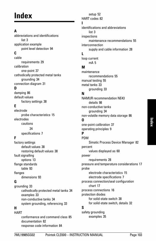
7ML19985GG02 Pointek CLS500 INSTRUCTION MANUAL Page 103
mm
mm
m
Index
Index
Aabbreviations and identifications
list 3application example
point level detection 94Ccable
requirements 29calibration
one-point 37cathodically protected metal tanks
grounding 34connection diagram 31Ddamping 86default values
factory settings 38Eelectrode
probe characteristics 15electrodes
cautions 24
specifications 7Ffactory settings
default values 38restoring default values 38
fault signallingoptions 13
flange standardstable 93
flangesdimensions 93
Ggrounding 33
cathodically protected metal tanks 34examples 33non-conductive tanks 34system grounding, referencing 33
HHART
conformance and command class 85documentation 82response code information 84
setup 52HART codes 82Iidentifications and abbreviations
list 3inspections
maintenance recommendations 55interconnection
supply and cable information 28Lloop current
mA 5Mmaintenance
recommendations 55manual testing 55metal tanks 33
grounding 33NNAMUR recommendation NE43
details 98non-conductive tanks
grounding 34non-volatile memory data storage 86Oone-point calibration 37operating principles 9PPDM
Simatic Process Device Manager 82percent
values displayed as 60power
requirements 28pressure and temperature considerations 17probe
electrode characteristics 15electrode specifications 7
process connection/seal configurationchart 17
process connections 16protection diodes
for solid-state switch 38for solid-state switch, details 32
Ssafety grounding
examples 35
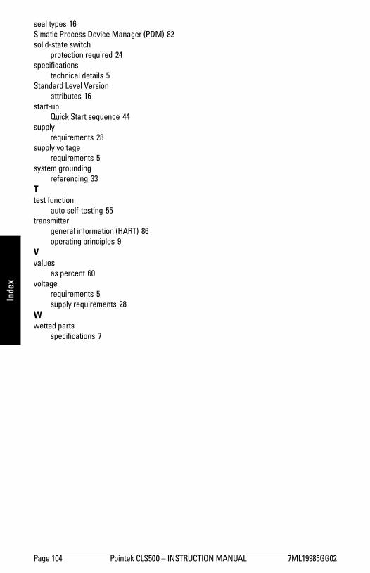
Page 104 Pointek CLS500 INSTRUCTION MANUAL 7ML19985GG02
mm
mm
m
Inde
xseal types 16Simatic Process Device Manager (PDM) 82solid-state switch
protection required 24specifications
technical details 5Standard Level Version
attributes 16start-up
Quick Start sequence 44supply
requirements 28supply voltage
requirements 5system grounding
referencing 33Ttest function
auto self-testing 55transmitter
general information (HART) 86operating principles 9
Vvalues
as percent 60voltage
requirements 5supply requirements 28
Wwetted parts
specifications 7
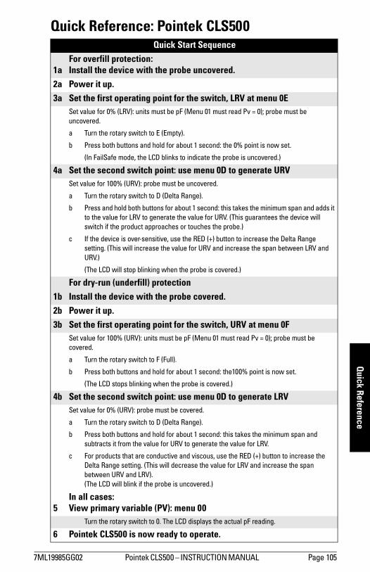
7ML19985GG02 Pointek CLS500 INSTRUCTION MANUAL Page 105
mm
mm
m
Quick Reference
Quick Reference: Pointek CLS500Quick Start Sequence
1aFor overfill protection:Install the device with the probe uncovered.
2a Power it up. 3a Set the first operating point for the switch, LRV at menu 0E
Set value for 0% (LRV): units must be pF (Menu 01 must read Pv = 0); probe must be uncovered.
a Turn the rotary switch to E (Empty).
b Press both buttons and hold for about 1 second: the 0% point is now set.
(In FailSafe mode, the LCD blinks to indicate the probe is uncovered.)
4a Set the second switch point: use menu 0D to generate URVSet value for 100% (URV): probe must be uncovered.
a Turn the rotary switch to D (Delta Range).
b Press and hold both buttons for about 1 second: this takes the minimum span and adds it to the value for LRV to generate the value for URV. (This guarantees the device will switch if the product approaches or touches the probe.)
c If the device is over-sensitive, use the RED (+) button to increase the Delta Range setting. (This will increase the value for URV and increase the span between LRV and URV.)
(The LCD will stop blinking when the probe is covered.)
For dry-run (underfill) protection1b Install the device with the probe covered.2b Power it up. 3b Set the first operating point for the switch, URV at menu 0F
Set value for 100% (URV): units must be pF (Menu 01 must read Pv = 0); probe must be covered.
a Turn the rotary switch to F (Full).
b Press both buttons and hold for about 1 second: the100% point is now set.
(The LCD stops blinking when the probe is covered.)
4b Set the second switch point: use menu 0D to generate LRVSet value for 0% (URV): probe must be covered.
a Turn the rotary switch to D (Delta Range).
b Press both buttons and hold for about 1 second: this takes the minimum span and subtracts it from the value for URV to generate the value for LRV.
c For products that are conductive and viscous, use the RED (+) button to increase the Delta Range setting. (This will decrease the value for LRV and increase the span between URV and LRV).(The LCD will blink if the probe is uncovered.)
5In all cases:View primary variable (PV): menu 00
Turn the rotary switch to 0. The LCD displays the actual pF reading.
6 Pointek CLS500 is now ready to operate.
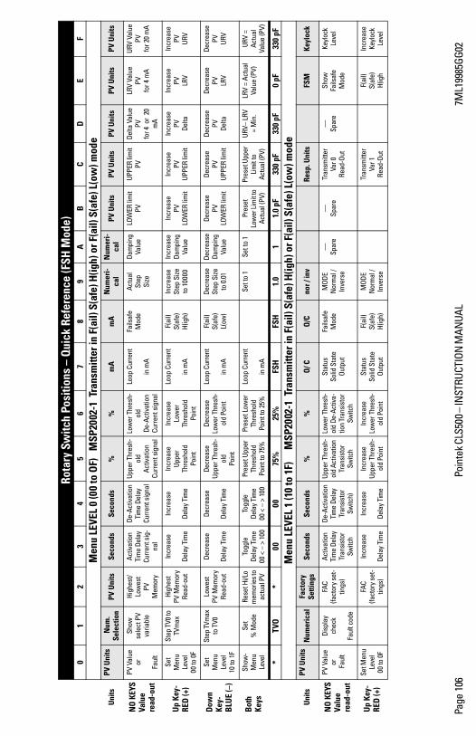
Page
106
Poin
tek C
LS50
0 IN
STRU
CTIO
N M
ANUA
L 7M
L199
85GG
02
Ro
tary
Sw
itch
Posi
tions
– Q
uick
Ref
eren
ce (F
SH M
ode)
01
23
45
67
89
AB
CD
EF
M
enu
LEVE
L 0
(00
to O
F)
MSP
2002
-1 T
rans
mitt
er in
F(a
il) S
(afe
) H(ig
h) o
r F(a
il) S
(afe
) L(o
w) m
ode
Uni
tsPV
Uni
ts N
um.
Sele
ctio
nPV
Uni
tsSe
cond
sSe
cond
s%
%m
Am
AN
umer
i-ca
lN
umer
i-ca
lPV
Uni
tsPV
Uni
tsPV
Uni
tsPV
Uni
tsPV
Uni
ts
NO
KEY
SVa
lue
read
-out
PV V
alue
or
Faul
t
Show
se
lect
PV
varia
ble
High
est/
Low
est
PVM
emor
y
Activ
atio
nTi
me
Dela
yCu
rren
t sig
-na
l
De-A
ctiv
atio
n Ti
me
Dela
yCu
rren
t sig
nal
Uppe
r Thr
esh-
old
Activ
atio
nCu
rren
t sig
nal
Low
er T
hres
h-ol
d De
-Act
ivat
ion
Curr
ent s
igna
l
Loop
Cur
rent
in m
A
Fails
afe
Mod
eAc
tual
Step
Size
Dam
ping
Valu
eLO
WER
lim
itPV
UPPE
R lim
itPV
Delta
Val
uePV
fo
r 4 o
r 20
m
A
LRV
Valu
ePV
fo
r 4 m
A
URV
Valu
ePV
for 2
0 m
A
Up
Key-
RED
(+)
Set
Men
u Le
vel
00 to
0F
Step
TV0
to
TVm
axHi
ghes
tPV
Mem
ory
Read
-out
Incr
ease
Dela
y Ti
me
Incr
ease
Dela
y Ti
me
Incr
ease
Up
per
Thre
shol
dPo
int
Incr
ease
Lo
wer
Th
resh
old
Poin
t
Loop
Cur
rent
in m
A
F(ai
l)
S(
afe)
H(
igh)
Incr
ease
St
ep S
ize
to 1
0000
Incr
ease
Da
mpi
ng
Valu
e
Incr
ease
PV
LO
WER
lim
it
Incr
ease
PV
UP
PER
limit
Incr
ease
PV Delta
Incr
ease
PV
LRV
Incr
ease
PV URV
Dow
n Ke
y-B
LUE
(–)
Set
Men
u Le
vel
10 to
1F
Step
TVm
ax
to T
V0Lo
wes
tPV
Mem
ory
Read
-out
Decr
ease
Dela
y Ti
me
Decr
ease
Dela
y Ti
me
Decr
ease
Up
per T
hres
h-ol
dPo
int
Decr
ease
Lo
wer
Thr
esh-
old
Poin
t
Loop
Cur
rent
in m
A
F(ai
l)
S(
afe)
L(ow
)
Decr
ease
St
ep S
ize
to 0
.01
Decr
ease
Da
mpi
ng
Valu
e
Decr
ease
PV
LO
WER
lim
it
Decr
ease
PV
UP
PER
limit
Decr
ease
PV Delta
Decr
ease
PV
LRV
Decr
ease
PV URV
Both
Ke
ys
Show
-M
enu
Leve
l
Set
%
Mod
eRe
set H
i/Lo
mem
orie
s to
actu
al P
V
Togg
leDe
lay
Tim
e00
<
> 1
00
Togg
leDe
lay
Tim
e00
<
> 1
00
Pres
et U
pper
Th
resh
old
Poin
t to
75%
Pres
et L
ower
Th
resh
old
Poin
t to
25%
Loop
Cur
rent
in m
A
Set t
o 1
Set t
o 1
Pres
etLo
wer
Lim
it to
Ac
tual
(PV)
Pres
et U
pper
Li
mit
to
Actu
al (P
V)
URV
LRV
=
Min
.LR
V =
Actu
al
Valu
e (P
V)UR
V =
Actu
al
Valu
e (P
V)
*TV
O*
0000
75%
25%
FSH
FSH
1.0
11.
0 pF
330
pF33
0 pF
0 pF
330
pF
M
enu
LEVE
L 1
(10
to 1
F)
MSP
2002
-1 T
rans
mitt
er in
F(a
il) S
(afe
) H(ig
h) o
r F(a
il) S
(afe
) L(o
w) m
ode
Uni
tsPV
Uni
tsN
umer
ical
Fact
ory
Setti
ngs
Seco
nds
Seco
nds
%%
O/ C
O/C
nor /
inv
Resp
. Uni
tsFS
MKe
yloc
k
NO
KEY
SVa
lue
read
-out
PV V
alue
or
Fau
lt
Dis
play
ch
eck
Faul
t cod
e
FAC
(fact
ory
set-
tings
)
Activ
atio
n Ti
me
Dela
y Tr
ansi
stor
Sw
itch
De-A
ctiv
atio
n Ti
me
Dela
y Tr
ansi
stor
Sw
itch)
Uppe
r Thr
esh-
old
Activ
atio
n Tr
ansi
stor
Sw
itch
Low
er T
hres
h-ol
d De
-Act
iva-
tion
Tran
sist
or
Switc
h
Stat
us
Solid
Sta
te
Outp
ut
Fails
afe
Mod
eM
ODE
Nor
mal
/ In
vers
e
Sp
are
Sp
are
Tran
smitt
er
Var 0
Re
ad-O
ut
Sp
are
Show
Fails
afe
M
ode
Keyl
ock
Leve
l
Up
Key-
RED
(+)
Set M
enu
Leve
l00
to 0
F
FAC
(fact
ory
set-
tings
)
Incr
ease
Dela
y Ti
me
Incr
ease
Dela
y Ti
me
Incr
ease
Up
per T
hres
h-ol
d Po
int
Incr
ease
Lo
wer
Thr
esh-
old
Poin
t
Stat
us
Solid
Sta
te
Outp
ut
F(ai
l)
S(
afe)
H(
igh)
MOD
EN
orm
al /
Inve
rse
Tran
smitt
er
Var 1
Re
ad-O
ut
F(ai
l)
S(af
e)
H(ig
h
Incr
ease
Ke
yloc
k Le
vel
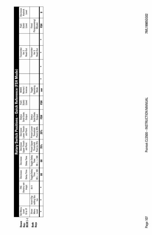
Page
107
Poin
tek C
LS50
0 IN
STRU
CTIO
N M
ANUA
L 7M
L199
85GG
02
Dow
n Ke
y-B
LUE
(–)
Set M
enu
Leve
l 10
to 1
F
FAC
(fact
ory
set-
tings
)
Decr
ease
Dela
y Ti
me
Decr
ease
Dela
y Ti
me
Decr
ease
Up
per T
hres
h-ol
d Po
int
Decr
ease
Lo
wer
Thr
esh-
old
Poin
t
Stat
us
Solid
Sta
te
Outp
ut
F(ai
l)
S(
afe)
L(ow
)
MOD
EN
orm
al /
Inve
rse
Tran
smitt
er
Var 2
Re
ad-O
ut
F(ai
l)
S(af
e)
L(
ow)
Decr
ease
Ke
yloc
k Le
vel
Both
Ke
ys
Show
M
enu
Leve
l
Inve
rt S
ig-
nalli
ng S
ta-
tus
do it
To
ggle
Del
ay
Tim
e 00
< -
> 10
0
Togg
le D
elay
Ti
me
00 <
- >
100
Pres
et U
pper
Th
resh
old
Poin
t to
75%
Pres
et L
ower
Th
resh
old
Poin
t to
25%
Stat
us
Solid
Sta
te
Outp
ut
Togg
le
Ope
ratin
g M
ode
Tran
smitt
er
Var 3
Re
ad-O
ut
F(re
e)
P(ro
gram
min
g)
M(o
de)
**
*00
0075
%25
%FS
HFS
Hno
r*
**
*FS
H0
Ro
tary
Sw
itch
Posi
tions
– Q
uick
Ref
eren
ce (F
SH M
ode)
Page 108 Pointek CLS500 INSTRUCTION MANUAL 7ML19985GG02
mm
mm
m
Qui
ck R
efer
ence
Free Programming Mode
Pointek CLS500 is most often used in FailSafe High or FailSafe Low mode (with linked alarm and fault signalling functions) selected at menu 1E. However, Free Programming Mode is an alternative.
In Free Programming Mode all menu items operate independently, and continuous level measurement, with a mA signal proportional to level, is available.
A chart showing the combinations of rotary switch positions and button presses for using Free Programming Mode is shown on the next page.
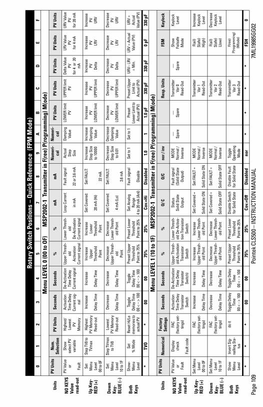
Page
109
Poin
tek C
LS50
0 IN
STRU
CTIO
N M
ANUA
L 7M
L199
85GG
02
Rota
ry S
witc
h Po
sitio
ns –
Qui
ck R
efer
ence
(FP
M M
ode)
0
12
34
56
78
9A
BC
DE
F
M
enu
LEVE
L 0
(00
to O
F)
M
SP20
02-1
Tra
nsm
itter
in F
(ree
) P(ro
gram
min
g) M
(ode
)
Uni
tsPV
Uni
ts N
um.
Sele
ctio
nPV
Uni
tsSe
cond
sSe
cond
s%
%m
Am
AN
umer
i-ca
lN
umer
i-ca
lPV
Uni
tsPV
Uni
tsPV
Uni
tsPV
Uni
tsPV
Uni
ts
NO
KEY
SVa
lue
read
-out
PV V
alue
or
Faul
t
Show
se
lect
PV
varia
ble
High
est/
Low
est
PVM
emor
y
Activ
atio
nTi
me
Dela
yCu
rren
t sig
-na
l
De-A
ctiv
atio
n Ti
me
Dela
yCu
rren
t sig
nal
Uppe
r Thr
esh-
old
Activ
atio
nCu
rren
t sig
nal
Low
er T
hres
h-ol
d De
-Act
ivat
ion
Curr
ent s
igna
l
Loop
Cur
rent
in m
A
Faul
t sig
nal
22 o
r 3.6
mA
Actu
alSt
epSi
ze
Dam
ping
Valu
eLO
WER
lim
itPV
UPPE
R lim
itPV
Delta
Val
uePV
fo
r 4 o
r 20
m
A
LRV
Valu
ePV
fo
r 4 m
A
URV
Val
uePV
for 2
0 m
A
Up
Key-
RED
(+)
Set
Men
u Le
vel
00 to
0F
Step
TV0
to
TVm
axHi
ghes
tPV
Mem
ory
Read
-out
Incr
ease
Dela
y Ti
me
Incr
ease
Dela
y Ti
me
Incr
ease
Up
per
Thre
shol
dPo
int
Incr
ease
Lo
wer
Th
resh
old
Poin
t
Set C
over
ed:
20 m
A (H
i)
Set F
AULT
:
22 m
A
Incr
ease
St
ep S
ize
to 1
0000
Incr
ease
Da
mpi
ng
Valu
e
Incr
ease
PV
LO
WER
lim
it
Incr
ease
PV
UP
PER
limit
Incr
ease
PV Delta
Incr
ease
PV
LRV
Incr
ease
PV URV
Dow
n Ke
y-B
LUE
(–)
Set
Men
u Le
vel
10 to
1F
Step
TVm
ax
to T
V0Lo
wes
tPV
Mem
ory
Read
-out
Decr
ease
Dela
y Ti
me
Decr
ease
Dela
y Ti
me
Decr
ease
Up
per T
hres
h-ol
dPo
int
Decr
ease
Lo
wer
Thr
esh-
old
Poin
t
Set C
over
ed:
4 m
A (L
o)
Set F
AULT
:
3.6
mA
Decr
ease
St
ep S
ize
to 0
.01
Decr
ease
Da
mpi
ng
Valu
e
Decr
ease
PV
LO
WER
lim
it
Decr
ease
PV
UP
PER
limit
Decr
ease
PV Delta
Decr
ease
PV
LRV
Decr
ease
PV URV
Both
Ke
ys
Show
-M
enu
Leve
l
Set
%
Mod
eRe
set H
i/Lo
mem
orie
s to
actu
al P
V
Togg
leDe
lay
Tim
e00
<
> 1
00
Togg
leDe
lay
Tim
e00
<
> 1
00
Pres
et U
pper
Th
resh
old
Poin
t to
75%
Pres
et L
ower
Th
resh
old
Poin
t to
25%
Set A
nalo
g Ra
nge
4 to
20
mA
(Anl
)
Faul
t sig
nal
Dis
able
Set t
o 1
Set t
o 1
Pres
etLo
wer
Lim
it to
Ac
tual
(PV)
Pres
et U
pper
Li
mit
to
Actu
al (P
V)
URV
LRV
=
Min
.LR
V =
Actu
al
Valu
e (P
V)UR
V =
Actu
al
Valu
e (P
V)
*TV
O*
0000
75%
25%
Cov.
=Hi
Dis
able
d1.
01
1.0
pF33
0 pF
330
pF0
pF33
0 pF
M
enu
LEVE
L 1
(10
to 1
F)
MSP
2002
-1 T
rans
mitt
er in
F(re
e) P
(rog
ram
min
g) M
(ode
)
Uni
tsPV
Uni
tsN
umer
ical
Fact
ory
Setti
ngs
Seco
nds
Seco
nds
%%
O/ C
O/C
nor /
inv
Resp
. Uni
tsFS
MKe
yloc
k
NO
KEY
SVa
lue
read
-out
PV V
alue
or
Fau
lt
Dis
play
ch
eck
Faul
t cod
e
FAC
(fact
ory
set-
tings
)
Activ
atio
n Ti
me
Dela
y Tr
ansi
stor
Sw
itch
De-A
ctiv
atio
n Ti
me
Dela
y Tr
ansi
stor
Sw
itch)
Uppe
r Thr
esh-
old
Activ
atio
n Tr
ansi
stor
Sw
itch
Low
er T
hres
h-ol
d De
-Act
iva-
tion
Tran
sist
or
Switc
h
Stat
us
Solid
Sta
te
Outp
ut
Faul
t sig
nal
(Sol
id S
tate
Ou
tput
)
MOD
EN
orm
al /
Inve
rse
Sp
are
Sp
are
Tran
smitt
er
Var 0
Re
ad-O
ut
Sp
are
Show
Fa
ilsaf
e
Mod
e
Keyl
ock
Leve
l
Up
Key-
RED
(+)
Set M
enu
Leve
l00
to 0
F
FAC
(fact
ory
set-
tings
)
Incr
ease
Dela
y Ti
me
Incr
ease
Dela
y Ti
me
Incr
ease
Up
per T
hres
h-ol
d Po
int
Incr
ease
Lo
wer
Thr
esh-
old
Poin
t
Set C
over
ed =
So
lid S
tate
ON
Set F
AULT
=
Solid
Sta
te O
N
MOD
EN
orm
al /
Inve
rse
Tran
smitt
er
Var 1
Re
ad-O
ut
F(ai
l)
S(af
e)
H(
igh)
Incr
ease
Ke
yloc
k Le
vel
Dow
n Ke
y-B
LUE
(–)
Set M
enu
Leve
l 10
to 1
F
FAC
(fact
ory
set-
tings
)
Decr
ease
Dela
y Ti
me
Decr
ease
Dela
y Ti
me
Decr
ease
Up
per T
hres
h-ol
d Po
int
Decr
ease
Lo
wer
Thr
esh-
old
Poin
t
Set C
over
ed =
So
lid S
tate
OFF
Set F
AULT
=
Solid
Sta
te O
FF
MOD
EN
orm
al /
Inve
rse
Tran
smitt
er
Var 2
Re
ad-O
ut
F(ai
l)
S(af
e)
L(ow
)
Decr
ease
Ke
yloc
k Le
vel
Both
Ke
ys
Show
M
enu
Leve
l
Inve
rt S
ig-
nalli
ng S
ta-
tus
do it
To
ggle
Del
ay
Tim
e 00
< -
> 10
0
Togg
le D
elay
Ti
me
00 <
- >
100
Pres
et U
pper
Th
resh
old
Poin
t to
75%
Pres
et L
ower
Th
resh
old
Poin
t to
25%
Disa
ble
Switc
h fo
r Sol
id S
tate
Di
sabl
e Fa
ult
for S
olid
Sta
teTo
ggle
Op
erat
ing
Mod
e
Tran
smitt
er
Var 3
Re
ad-O
ut
F(re
e)
P(ro
gram
min
g)
(M(o
de)
**
*00
0075
%25
%Co
v.=O
ffD
isab
led
nor
**
**
FSH
0

Notes
Notes.fm Page 2 Thursday, October 11, 2001 8:48 AM

IQ300IX.fm Page 5 Tuesday, October 2, 2001 1:43 PM
*7ml19985GG02*Rev. 2.0
www.siemens.com/processautomation
Siemens Milltronics Process Instruments Inc.1954Technology Drive, P.O. Box 4225Peterborough, ON, Canada K9J 7B1Tel: (705) 745-2431 Fax: (705) 741-0466Email: [email protected]
Siemens Milltronics Process Instruments Inc. 2009Subject to change without prior notice
Printed in Canada