Embed Size (px)
Citation preview
Functional Safety Manual June 2009
CLS500/LC500pointek
06/2009
Supplement to device manual
Pointek CLS500 series: 7ML5601*-Z C20, 7ML5602*-Z C20, 7ML5603*-Z C20, 7ML5604*-Z C20 SITRANS LC500 7ML5513*-Z C20, 7ML5515*-Z C20, 7ML5517*-Z C20, 7ML5521*-Z C20, 7ML5523*-Z C20
Introduction
1 General safety instructions
2 Device-specific safety instructions
3 Appendix
A List of abbreviations / acronyms
B
Level Switch Pointek CLS500 SITRANS LC500 SIL Safety Manual

Siemens AG
Safety manual 2 of 19 Pointek CLS500, SITRANS LC500
Safety Guidelines
This manual contains notices you have to observe in order to ensure your personal safety, as well as to prevent damage to property. The notices referring to your personal safety are highlighted in the manual by a safety alert symbol, notices referring only to property damage have no safety alert symbol. These notices shown below are graded according to the degree of danger.
Danger
indicates that death or severe personal injury will result if proper precautions are not taken.
Warning
indicates that death or severe personal injury may result if proper precautions are not taken.
Caution
with a safety alert symbol, indicates that minor personal injury can result if proper precautions are not taken.
Caution
without a safety alert symbol, indicates that property damage can result if proper precautions are not taken.
Notice
indicates that an unintended result or situation can occur if the corresponding information is not taken into account.
If more than one degree of danger is present, the warning notice representing the highest degree of danger will be used. A notice warning of injury to persons with a safety alert symbol may also include a warning relating to property damage.
Qualified Personnel
The device/system may only be set up and used in conjunction with this documentation. Commissioning and operation of a device/system may only be performed by qualified personnel. Within the context of the safety notes in this documentation qualified persons are defined as persons who are authorized to commission, ground and label devices, systems and circuits in accordance with established safety practices and standards.
Prescribed Usage
Note the following:
Warning
This device may only be used for the applications described in the catalog or the technical description and only in connection with devices or components from other manufacturers which have been approved or recommended by Siemens. Correct, reliable operation of the product requires proper transport, storage, positioning and assembly as well as careful operation and maintenance.
Trademarks
All names identified by ® are registered trademarks of the Siemens AG. The remaining trademarks in this publication may be trademarks whose use by third parties for their own purposes could violate the rights of the owner.
Copyright Siemens AG 2009. All rights reserved.
The distribution and duplication of this document or the utilization and
transmission of its contents are not permitted without express written permission.
Offenders will be liable for damages. All rights, including rights created by patent
grant or registration of a utility model or design, are reserved.
Siemens AG
Automation and Drives
Postfach 4848, 90327 Nuremberg, Germany
Siemens Aktiengesellschaft
Disclaimer of Liability
We have reviewed the contents of this publication to ensure consistency with the
hardware and software described. Since variance can not be precluded entirely,
we cannot guarantee full consistency. However, the information in this publication
is reviewed regularly and any necessary corrections are included in subsequent
editions.
Siemens AG 2009
Technical data subject to change
A5E00442122-01
Siemens AG
Safety manual 3 of 19 Pointek CLS500, SITRANS LC500
Table of contents 1 Introduction........................................................................................................4
1.1 Purpose of this document..............................................................................4 1.2 Required documentation ...............................................................................4 1.3 History ..........................................................................................................4 1.4 More information...........................................................................................5
2 General safety instructions ...............................................................................6 2.1 Safety-instrumented system ..........................................................................6 2.2 Safety Integrity Level (SIL) ............................................................................9
3 Device-specific safety instructions.................................................................11 3.1 Applications ................................................................................................11 3.2 Safety function............................................................................................11 3.3 Settings ......................................................................................................12 3.4 Behavior in case of faults ............................................................................13 3.5 Maintenance / Checking..............................................................................13 3.6 Safety characteristics ..................................................................................14
A Appendix ..........................................................................................................15 A.1 SIL Declaration of Conformity......................................................................15 A.2 Exida Test Report (extract) .........................................................................16
B List of abbreviations/acronyms ......................................................................18 B.1 Abbreviations..............................................................................................18 Glossary ...............................................................................................................19
Siemens AG
4 of 19 Safety manual Pointek CLS500, SITRANS LC500
1
1 Introduction
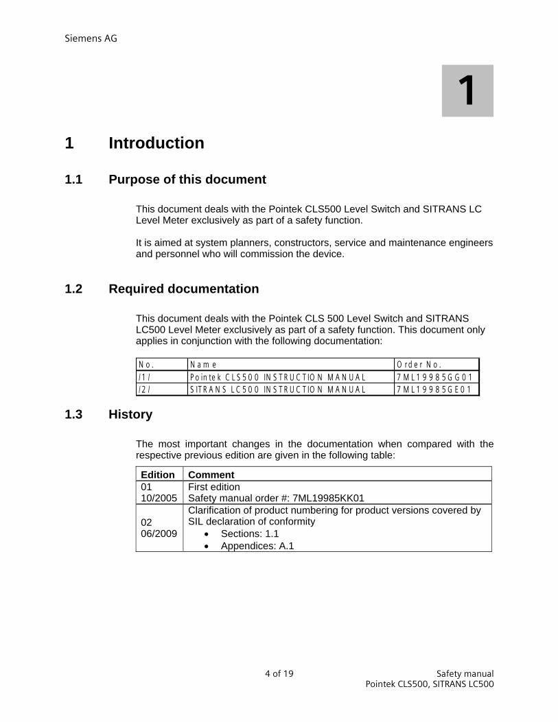
1.1 Purpose of this document
This document deals with the Pointek CLS500 Level Switch and SITRANS LC Level Meter exclusively as part of a safety function.
It is aimed at system planners, constructors, service and maintenance engineers and personnel who will commission the device.
1.2 Required documentation
This document deals with the Pointek CLS 500 Level Switch and SITRANS LC500 Level Meter exclusively as part of a safety function. This document only applies in conjunction with the following documentation:
N o . N a m e O r d e r N o ./ 1 / P o in te k C L S 5 0 0 IN S T R U C T IO N M A N U A L 7 M L 1 9 9 8 5 G G 0 1/ 2 / S IT R A N S L C 5 0 0 IN S T R U C T IO N M A N U A L 7 M L 1 9 9 8 5 G E 0 1
1.3 History
The most important changes in the documentation when compared with the respective previous edition are given in the following table:
Edition Comment 01 10/2005
First edition Safety manual order #: 7ML19985KK01
02 06/2009
Clarification of product numbering for product versions covered by SIL declaration of conformity
• Sections: 1.1 • Appendices: A.1
Siemens AG
Safety manual 5 of 19 Pointek CLS500, SITRANS LC500
1.4 More information Information The contents of these instructions shall not become part of or modify any prior or existing agreement, commitment or legal relationship. All obligations on the part of Siemens AG are contained in the respective sales contract which also contains the complete and solely applicable warranty conditions. Any statements contained herein do not create new warranties or modify the existing warranty. The content reflects the technical status at the time of printing. We reserve the right to make technical changes in the course of further development. References If there are references to further information on an aspect described here, these will always be found at the end of a chapter under “See also”.
Siemens regional offices If you need more information or have particular problems which are not covered sufficiently by the operating instructions, contact your local Siemens Regional Office. You will find the address of your local Siemens Regional Office on the Internet at https://www.siemens.com/processinstrumentation/contacts
Product information on the Internet
The Instruction Manual is on the supplied CD and is also available on the Siemens Level homepage on the Internet: www.siemens.com/level
On the supplied CD, you will also find the product catalog sheet containing the ordering data, the Device Install software for SIMATIC PDM for subsequent installation, and the generic station description (GSD).
See also
Siemens Regional Offices (https://www.siemens.com/processinstrumentation/contacts)
Product information and Instruction Manuals on the Internet (http://www.siemens.com/level)

Siemens AG
6 of 19 Safety manual Pointek CLS500, SITRANS LC500
2
2 General safety instructions
2.1 Safety-instrumented system Definition: Safety-instrumented system A safety-instrumented system executes the safety functions that are required to achieve or maintain a safe status in a system. It consists of a sensor logic unit/ control system, and final controlling element. Example:
A safety-instrumented system is made up of a pressure transmitter, a logic unit and a control valve.
Definition: Safety function Defined function executed by a safety-instrumented system with the objective of achieving or maintaining a safe system taking into account a defined dangerous occurrence. Example: Level switch for overflow protection Definition: Dangerous failure Failure with the potential to bring the safety-instrumented system into a dangerous on nonfunctional status. Description The sensor logic unit/control system a final controlling element combine to form a safety-instrumented system, which executes a safety function.
Notes
This document deals with the Pointek CLS500 and SITRANS LC500 exclusively as part of a safety function. Pointek CLS500 and SITRANS LC500 devices covered by SIL declaration of conformity are identified by the “-Z C20” suffix of their product number which is printed on the device nameplate.

Siemens AG
Safety manual 7 of 19 Pointek CLS500, SITRANS LC500
Control System PLC Final controlling Element Valve with actuator Sensor and positioner Figure 2-1 Example of a safety-instrumented system Function
The SITRANS LC500 and Pointek CLS500 are capacitance instruments for level and interface measurements. They have a modular configuration of probe and 2-wire transmitter as one instrument. The integrated zener safety barrier blocks excess energy from the transmitter to the sensor for intrinsically safe conditions.
The SITRANS LC500 can be used with rod or cable probes and allows for probe versions up to 5.5 m (18 ft) for the rod version and up to 35 m (115 ft) for the cable version. The Pointek CLS500 can be used with rod type probes up to 1 m (3.3 ft) in length. The measurement is unaffected by moisture, vapors, foam, temperature and pressure variations, or material build-up around the mounting glands.
The SITRANS LC500 and Pointek CLS500 are two wire smart devices. For safety-instrumented systems usage it is assumed that the 4-20 mA output is used as the primary safety variable. In addition to the 4-20 mA output, a solid state switch relay output is available. For the Failure Modes, Effects and Diagnostic Analysis it was assumed that the relay output is used to signal diagnostic information (in addition to the current signaling according to NAMUR NE 43).

Siemens AG
8 of 19 Safety manual Pointek CLS500, SITRANS LC500
The following table gives an overview of the different versions that were considered in the FMEDA of the SITRANS LC500 and Pointek CLS500. This corresponds with type numbers: MSP2002-1 (330pF), MSP2002-2 (3300 pF), and MSP2002-3 (6600pF).
SITRANS LC5004-20/20-4mA signal & 2-state functionality 4 or 20/20 or 4 mA, on or off
Pointek CLS5004-20/20-4mA signal & 2-state functionality 4 or 20/20 or 4 mA, on or off

Siemens AG
Safety manual 9 of 19 Pointek CLS500, SITRANS LC500
2.2 Safety Integrity Level (SIL) Definition: SIL The international standard IEC 61508 defines four discrete Safety Integrity Levels (SIL) from SIL 1 to SIL 4. Each level corresponds to the probability range for the failure in a safety function. The higher the SIL of the safety-instrumented system, the higher probability that the required safety function will work. The achievable SIL is determined by the following safety characteristics:
• Average probability of dangerous failure of a safety function in case of demand (PFDAVG)
• Hardware fault tolerance (HFT) • Safe failure fraction (SFF)
Description
The following table shows the dependency of the SIL on the average probability of dangerous failures of a safety function of the entire safety-instrumented system (PFDAVG). The table deals with “Low demand mode”, i.e. the safety function is required a maximum of once per year on average.
SIL PFDAVG 4 ≥ 10-5 … < 10-4 3 ≥ 10-4 … < 10-3 2 ≥ 10-3 … < 10-2 1 ≥ 10-2 … < 10-1
The “average probability of dangerous failures of the entire safety- instrumented system” (PFDAVG) is normally spilt between the three sub-systems in the following figure. Figure 2-2 PFDAVG distribution
Sensor e.g. level, pressure, etc.
Control system or logic unit e.g. PLC
Final contro-lling element e.g. valve with actuator and positioner
Siemens AG
10 of 19 Safety manual Pointek CLS500, SITRANS LC500
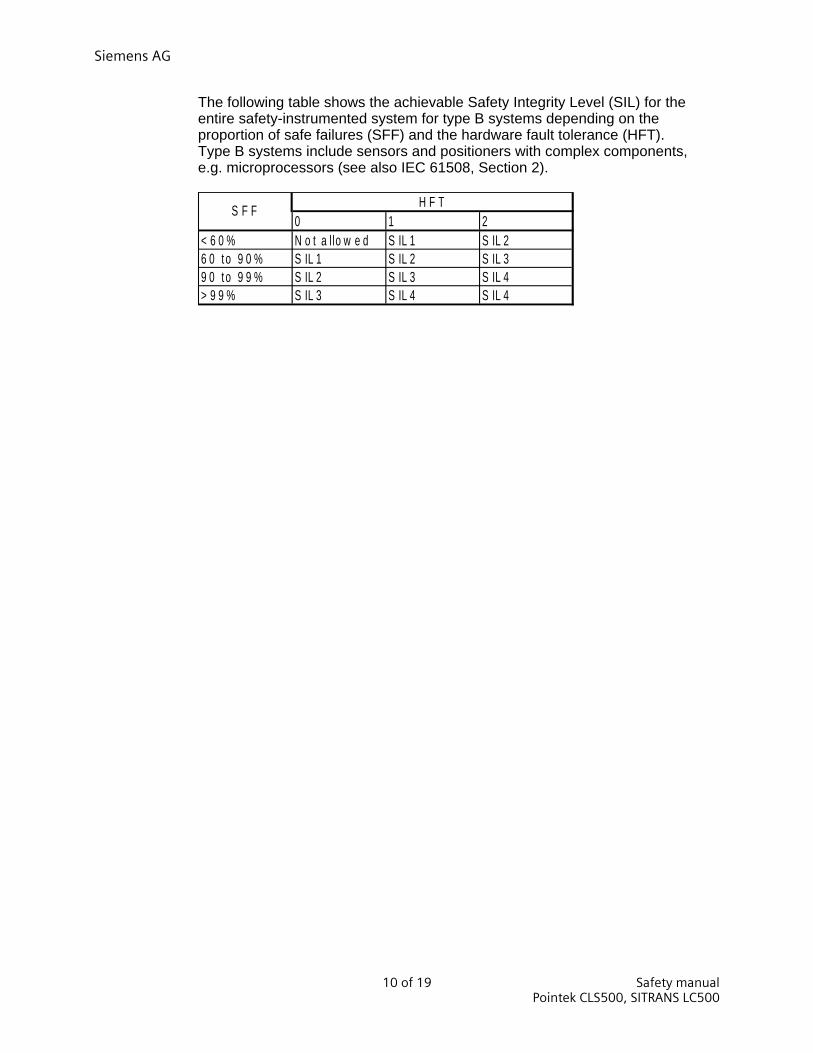
The following table shows the achievable Safety Integrity Level (SIL) for the entire safety-instrumented system for type B systems depending on the proportion of safe failures (SFF) and the hardware fault tolerance (HFT). Type B systems include sensors and positioners with complex components, e.g. microprocessors (see also IEC 61508, Section 2).
0 1 2< 6 0 % N o t a l lo w e d S IL 1 S IL 26 0 t o 9 0 % S IL 1 S IL 2 S IL 39 0 t o 9 9 % S IL 2 S IL 3 S IL 4> 9 9 % S IL 3 S IL 4 S IL 4
H F TS F F
Siemens AG
Safety manual 11 of 19 Pointek CLS500, SITRANS LC500
3
3 Device-specific safety instructions
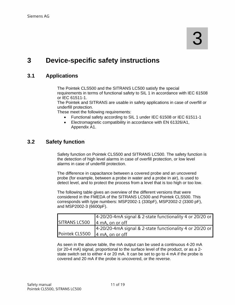
3.1 Applications
The Pointek CLS500 and the SITRANS LC500 satisfy the special requirements in terms of functional safety to SIL 1 in accordance with IEC 61508 or IEC 61511-1. The Pointek and SITRANS are usable in safety applications in case of overfill or underfill protection.
These meet the following requirements: • Functional safety according to SIL 1 under IEC 61508 or IEC 61511-1 • Electromagnetic compatibility in accordance with EN 61326/A1,
Appendix A1.
3.2 Safety function
Safety function on Pointek CLS500 and SITRANS LC500. The safety function is the detection of high level alarms in case of overfill protection, or low level alarms in case of underfill protection. The difference in capacitance between a covered probe and an uncovered probe (for example, between a probe in water and a probe in air), is used to detect level, and to protect the process from a level that is too high or too low.
The following table gives an overview of the different versions that were considered in the FMEDA of the SITRANS LC500 and Pointek CLS500. This corresponds with type numbers: MSP2002-1 (330pF), MSP2002-2 (3300 pF), and MSP2002-3 (6600pF).
SITRANS LC5004-20/20-4mA signal & 2-state functionality 4 or 20/20 or 4 mA, on or off
Pointek CLS5004-20/20-4mA signal & 2-state functionality 4 or 20/20 or 4 mA, on or off
As seen in the above table, the mA output can be used a continuous 4-20 mA (or 20-4 mA) signal, proportional to the surface level of the product, or as a 2-state switch set to either 4 or 20 mA. It can be set to go to 4 mA if the probe is covered and 20 mA if the probe is uncovered, or the reverse.
Siemens AG
12 of 19 Safety manual Pointek CLS500, SITRANS LC500
Warning
The binding settings and conditions are listed in the “Settings” and “Safety characteristics” sections. These conditions must be met in order to fulfill the safety function.
Reference See chapter 1.2 See also Settings (Chapter 3.3) Safety characteristics (Chapter 3.6)
3.3 Settings
After assembly and commissioning in line with the device manual, the parameter settings should be made for the safety function as described in applicable reference /1/ or /2/.
Reference Device manual Protection against configuration changes
After configuration of the Pointek CLS500 or SITRANS LC500 you should fix the housing cover so that the device is protected against unwanted and unauthorized changes/operation.
Checking the safety function
After installation you shall test that the Pointek/SITRANS is switching correctly. First you shall test the basic functionality of the Pointek/SITRANS as described in device manual /1/ or /2/. To test the full safety case the sensor shall be covered. In this condition, the Pointek/SITRANS must switch to high level alarm (safety position).

Siemens AG
Safety manual 13 of 19 Pointek CLS500, SITRANS LC500
3.4 Behavior in case of faults Fault
The procedure in case of faults is described in the applicable device operating manual /1/ or /2/.
Repairs
Defective devices should be sent to the Repair Department with details of the fault and the cause. When ordering replacement devices, please specify the serial number of the original device. The serial number can be found on the nameplate. The address of the responsible repair center, contact, spare parts lists etc. can be found on the Internet at:
Reference www.siemens.com/automation/services&support www.automation.siemens.com/partner
3.5 Maintenance / Checking Checking function
We recommend that the functioning of the Pointek/SITRANS is checked at regular Intervals of one year. Check at least the following:
• Test the basic functionality of the Pointek/SITRANS as described in Device manual /1/ or /2/
Checking safety
You should regularly check the safety function of the entire safety circuit in line with IEC 61508/61511. The testing intervals are determined during circulation of each individual safety circuit in a system (PFDAVG). Recommended proof test interval is 1 year. On the Pointek/SITRANS Level Switch the following specific checks shall be carried out:
• Test the basic functionality of the Pointek/SITRANS as described in Device manual /1/ or /2/
• Test the full safety functionality by o Check the output state of Pointek/SITRANS if sensor is
uncovered : not switched o Cover the sensor: Pointek CLS500, SITRANS LC500 must
switch.
Siemens AG
14 of 19 Safety manual Pointek CLS500, SITRANS LC500
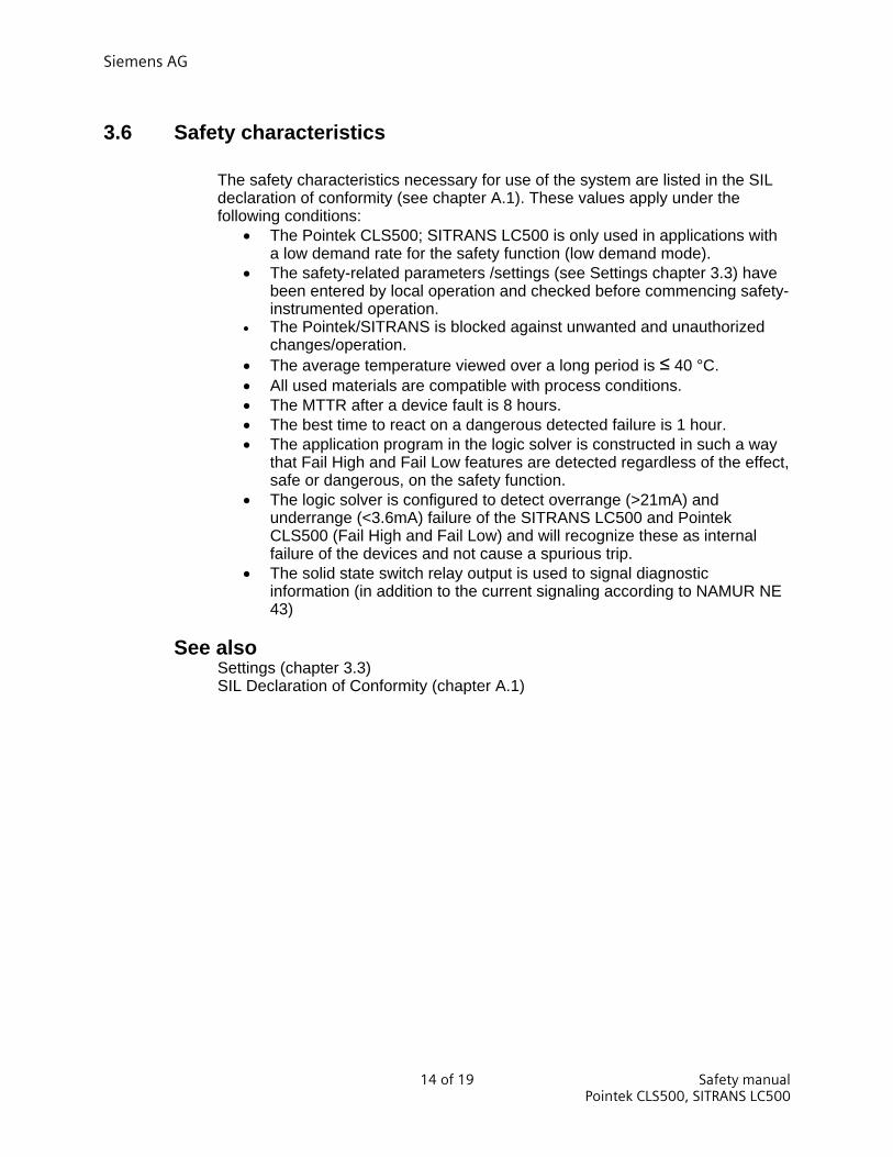
3.6 Safety characteristics
The safety characteristics necessary for use of the system are listed in the SIL declaration of conformity (see chapter A.1). These values apply under the following conditions:
• The Pointek CLS500; SITRANS LC500 is only used in applications with a low demand rate for the safety function (low demand mode).
• The safety-related parameters /settings (see Settings chapter 3.3) have been entered by local operation and checked before commencing safety-instrumented operation.
• The Pointek/SITRANS is blocked against unwanted and unauthorized changes/operation.
• The average temperature viewed over a long period is ≤ 40 °C. • All used materials are compatible with process conditions. • The MTTR after a device fault is 8 hours. • The best time to react on a dangerous detected failure is 1 hour. • The application program in the logic solver is constructed in such a way
that Fail High and Fail Low features are detected regardless of the effect, safe or dangerous, on the safety function.
• The logic solver is configured to detect overrange (>21mA) and underrange (<3.6mA) failure of the SITRANS LC500 and Pointek CLS500 (Fail High and Fail Low) and will recognize these as internal failure of the devices and not cause a spurious trip.
• The solid state switch relay output is used to signal diagnostic information (in addition to the current signaling according to NAMUR NE 43)
See also Settings (chapter 3.3) SIL Declaration of Conformity (chapter A.1)
Siemens AG
Safety manual 15 of 19 Pointek CLS500, SITRANS LC500
A Appendix
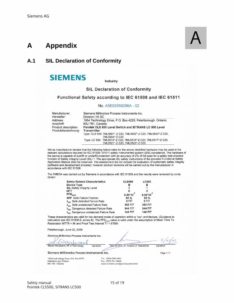
A.1 SIL Declaration of Conformity
A
Siemens AG
16 of 19 Safety manual Pointek CLS500, SITRANS LC500
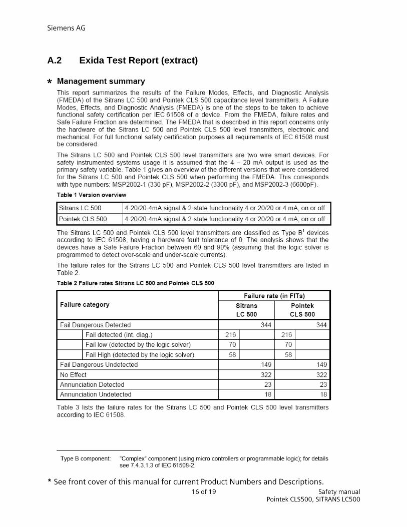
A.2 Exida Test Report (extract)
* See front cover of this manual for current Product Numbers and Descriptions.
*

Siemens AG
Safety manual 17 of 19 Pointek CLS500, SITRANS LC500

Siemens AG
18 of 19 Safety manual Pointek CLS500, SITRANS LC500
B
B List of abbreviations/acronyms
B.1 Abbreviations Abbreviation Full term in English Meaning
FIT Failure in Time Frequency of failure of the protective function HFT Hardware Fault Tolerance Hardware fault tolerance: Capability of a
function unit to continue executing a required function in the presence of faults or deviations.
MTBF Mean Time Between Failures Average period between two failures MTTR Mean Time To Restoration Average period between the occurrence of a
fault on a device or system and the repair PFD Probability of Failure on Demand Probability of dangerous failures of a safety
function on demand PFDAVG Average Probability of Failure on Demand Average probability of dangerous failures of a
safety function on demand PLC Programmable Logic Controller SIL Safety Integrity Level The international standard IEC 61508 defines
four discrete Safety Integrity Levels (SIL 1 to SIL 4). Each level corresponds to a range of probability for failure of a safety function. The higher the Safety Integrity Level of the safety-instrumented system, the lower the probability that it will not execute the required safety functions.
SFF Safe Failure Function Proportion of safe failures: Proportion of failures without the potential to bring the safety instrumented system into a dangerous on no permissible functional status.
TI Test Interval Testing interval of the protective function XooY "X out of Y" voting Classification and description of the safety-
instrumented system in terms of redundancy and the selection procedures used.
"Y" -Specifies how often the safety function is executed (redundancy).
"X" -Determines how many channels have to work correctly.
Example: Pressure measurement: 1oo2 architecture. A safety instrumented system decides that a specified pressure limit has been exceeded if one out of two pressure sensors reaches this limit. In a 1oo1 architecture, there is only one pressure sensor.
Siemens AG
Safety manual 19 of 19 Pointek CLS500, SITRANS LC500
Glossary Dangerous failure
Failure with the potential to bring the safety-instrumented system into a dangerous or nonfunctional status
Safety function
Defined function executed by a safety-instrumented system with the objective of achieving or maintaining a safe system status taking into account a defined dangerous occurrence.
Example: Limit pressure monitoring Safety Integrity Level SIL Safety-instrumented system
A safety-instrumented system excludes the safety functions that are required to achieve or maintain a safe status in a system. It consists of a sensor, logic unit/control system and final controlling element.
Example: A safety-instrumented system is made up of a pressure transmitter, a limit signal sensor and a control valve.
SIL
The international standard IEC 61508 defines four discrete Safety Integrity Levels (SIL) from SIL 1 to SIL 4. Each level corresponds to the probability range for the failure of a safety function. The higher the SIL of the safety-instrumented system, the higher the probability that the required safety function will work. The achievable SIL is determined by the following safety characteristics:
• Average probability of dangerous failure of a safety function in case of demand (PFDAVG)
• Hardware fault tolerance (HFT) • Safe failure fraction (SFF)

www.siemens.com/level
Siemens Milltronics Process Instruments Inc.1954Technology Drive, P.O. Box 4225Peterborough, ON, Canada K9J 7B1Tel: (705) 745-2431 Fax: (705) 741-0466Email: [email protected] *7ml19985KK02*
Rev. 2.0
Siemens Milltronics Process Instruments Inc. 2009Subject to change without prior notice
Printed in Canada