Embed Size (px)
Citation preview

Side by Side “Dragon 88”
China
production
New Range
2013

Chapter list
Installation
Safety Instruction, IFU & Installation
Appliance Dimensions
Range 2013 overview
Novelties / Project Scope
Novelties / Architecture
Novelties XXL Phase 4 Wave1 & Wave2
Wave2, Technical Features
SKU’s for EMEA
UK Models
Whirlpool Brand / UK Models
EMEA Models
Whirlpool Brand / EU Models
Bauknecht Brand / EU Models
Operations
Stealth UI application overview
Dispensing Models / Connectors
Non-Dispensing Models / Connectors
Key Assignment & Functions: Dispenser Models
Key Combination: Dispenser Models
Key Assignment & Functions: Non-Dispenser
Key Combination: Non-Dispenser Models
General Description of the User Interface
Control System
Minotaur Core Board / Block Diagrams
Minotaur Core Board / Connector Locations

Chapter list
Troubleshooting
Failure code: Power Outage
Service Diagnostics in “Normal Mode”
Activation of the “Service Diagnostics Routine”
Service Mode Navigation Method
User Interface Display Information
Service Test Routine Document
Functional characteristics
NTC Sensor – Refrigerator Compartment
NTC Sensor – Freezer Compartment
NTC Sensor Failure Management
Ice Water Valve
Ice-Maker Water Valve
Ice-Maker
Ice Crusher Motor
Dispenser Stepper Motor
Dispenser Paddle
Evaporator Defrost Cycle
Technical Data
Main Board
User Interface
Power Supply Board / 1x15W
Stepper Motor dispenser assy
Dispenser paddle
Dispenser LED
Ice Motor IDI 23
LED Lighting Side Walls
LED Lighting Top Fridge Compartment
Defrost Heater R600a
Fan Motors
Air Diffuser
Ice Maker Sankyo IDI 3
Filling Tube Heater
Water Valve Dual
Solenoid Water Valve
Overload Protector
Run-Capacitor

Chapter list
Repair Guide Line
Disassembling
Disassembling
Disassembling
Disassembling
Disassembling
Disassembling
Disassembling
Documents
NTC Table

Installation
Safety Instruction, IFU & Installation
IFU (it include also the installation instruction, the door removal, leveling and
alignment, product dimensions, electrical requirements & water supply requirements)
Attention:
• Carefully read the complete safety and operation instructions in the IFU (attached below).
• Attend the environmental regulations.
• Keep the healthy instructions, especially for the assembler and children.
• Read the Installation instruction before first installation.
Product Sheet for IDI versions (with dispenser unit & ice maker)
Product Sheet for non IDI versions (without dispenser unit & ice maker)

Installation
Appliance Dimensions
Front view:
- Height dimensions are shown with the
leveling legs extended to the minimum
height of ¹⁄₄" (6.35 mm) below the refrigerator.
When leveling legs are fully extended to
1" (25 mm) below the refrigerator,
add ³⁄₄" (19 mm) to the height dimensions.
•- The power cord is approximately
• 85" (215 cm) long.
Side view:

Installation
Appliance Dimensions
Top view:
•A. Dimensions may vary based on the model.
Door swing dimensions:
•- Location must permit doors to open to a minimum of 165°.
•- Allow 13⁷⁄₈" (35 cm) minimum space between the side wall and the
• freezer side of the refrigerator. Allow 18⁵⁄₈" (47 cm) minimum
• space between the side wall and the refrigerator side.
•NOTE: Dimensions may vary based on model.

Installation
Appliance Dimensions
Opening dimensions:
•- Height dimensions are shown with the leveling legs extended
to
• the minimum height of ¹⁄₄" (6.35 mm) below the refrigerator.
• When leveling legs are fully extended to 1" (25 mm) below
the
• refrigerator, add ³⁄₄" (19 mm) to the height dimensions.
•- Minimum fixed wall position is 13⁷⁄₈" (35 cm) from the freezer
door and 18⁵⁄₈" (47 cm) from the refrigerator door.

Range 2013 overview
Novelties / Project Scope
- Brand version: Whirlpool, Bauknecht, Ronshen & Hisense
- Energy class: A+ & A++
- Refrigerant: R600a / C-Pentane
- Capacity: 21 cuft = 595 litre
- Compressor: Standard & VCC versions
- Ice & Water: Non IDI & IDI3 Sankyo
- Evaporator: Single & Sequential Dual version
- Lighting: LED
- Filter: Air & Water (small/smart)
- Dispenser: Flush Dispenser (Victoria)
- Innovation: Nano shelves, 6th Sense, Home Bar, Plumbed water, Non-plumbed with Gravity Filters
- Architecture: 2 x 2 x 2
- Sound Level: 46 dBA
•A
++

Range 2013 overview
Novelties / Architecture
•2x2x2
Dimensions:
(cm) (cm)
Height 1750 1825
Width 830 905
Depth 610 736

Range 2013 overview
Novelties XXL Phase 4 Wave 1 & Wave 2
PRODUCTION AT CHANGXING (HUZHOU) IJV, CHINA
Production Dates Plan:
Wave 1 – June / July 2013
Wave 2 – End of 2013
Customer Benefits (both waves)
Better energy & capacity solution
Energy to A++ including dual evaporator
Capacity to 595l net
New controls & new LED lighting
Nano shelves anti spill solution
Improved air and water filtration (easier to access)
Better food preservation with dual evaporator
R600a versions
Wave 2: Non-plumbed version with gravity water system
Wave 2: New Home bar design
•Dragon 88 Wave 1
•Dragon 88 Wave 2
•follows Wave1 by approx 6
months
•(A++, Dual Evap, Gravity Water
Dispensing with Filter, Home Bar)

Range 2013 overview
•Gravity non-plumbed water dispensing
•SUK2 NP, SWER2 NP, SBK2 NP, SWER3 NP A++, SBK3 NP A++
Wave 2, Technical Features
•Dual Evaporator
•SWER4 A++, SUK4 A++, SBK4 A++, SC3 H, SA1 H, SA2 H
•A++ Energy for EMEA
•SWER3 NP A++, SBK3 NP A++, SWER3 A++, SBK3 A++
•SWER4 A++, SUK4 A++, SBK4 A++
•A
++

Range 2013 overview
Wave 2, Technical Features
•Home Bar
•SC3 H, SA1 H, SA2 H

Range 2013 overview
SKU’s for EMEA
12NC Brand Commercial Code Product Description Destination
850193611000 WH WSX1101 MS SWER1: no I&W dispenser, A+, nice fake inox EU (all WE+CE+EE+MEA)
850193611010 WH WSX1101 N SWER1: no I&W dispenser, A+, black EU (all WE+CE+EE+MEA)
850193611020 WH WSX1101 W SWER1: no I&W dispenser, A+, white EU (all WE+CE+EE+MEA)
850193615000 WH WSX1101 MS SUK1: no I&W dispenser, A+, nice fake inox UK
850193615010 WH WSX1101 N SUK1: no I&W dispenser, A+, black UK
850193615020 WH WSX1101 W SUK1: no I&W dispenser, A+, white UK
850193811000 WH WSX5172 MS SWER3: I&W dispenser, A+, nice fake inox EU (all WE+CE+EE+MEA)
850193811010 WH WSX5172 N SWER3: I&W dispenser, A+, black EU (all WE+CE+EE+MEA)
850193811020 WH WSX5172 W SWER3: I&W dispenser, A+, white EU (all WE+CE+EE+MEA)
850193815000 WH WSX5172 MS SUK2: I&W dispenser, A+, nice fake inox UK
850193815010 WH WSX5172 N SUK2: I&W dispenser, A+, black UK
850193815020 WH WSX5172 W SUK2: I&W dispenser, A+, white UK
850193911000 WH WSX5578 MS SWER3: I&W dispenser, A+, nice fake inox BK premium handles and interior different (bottle rack and snack compartment) EU (all WE+CE+EE+MEA)
850194011000 WH WSX7172 MS SWER3: I&W dispenser, A+, nice fake inox, Home Bar EU (all WE+CE+EE+MEA)
850194111000 WH WSX7578 MS
SWER3: I&W dispenser, A+, nice fake inox, BK premium handles and interior different (bottle rack and snack compartment),
Home Bar EU (all WE+CE+EE+MEA)
850194211000 WH WSX3111 MS SWER2NP: no plumbed Water dispenser, A+, nice fake inox EU (all WE+CE+EE+MEA)
850194211010 WH WSX3111 N SWER2NP: no plumbed water dispenser, A+, black EU (all WE+CE+EE+MEA)
850194215000 WH WSX3111 MS SUK2NP: no plumbed water dispenser, A+, nice fake inox UK
850194215010 WH WSX3111 N SUK2NP: no plumbed water dispenser, A+, black UK
850194211100 WH WSX31122 MS SWER3NP: no plumbed water dispenser, A++, nice fake inox EU (all WE+CE+EE+MEA)
850194211110 WH WSX31122 N SWER3NP: no plumbed water dispenser, A++, black EU (all WE+CE+EE+MEA)
850193811100 WH WSX51722 MS SWER3: I&W dispenser, A++, nice fake inox EU (all WE+CE+EE+MEA)
850193811110 WH WSX51722 N SWER3: I&W dispenser, A++, black EU (all WE+CE+EE+MEA)
850194511000 WH WSX53782 X SWER4: I&W dispenser, A++, inox, 6th Sense Fresh Control EU (all WE+CE+EE+MEA)
850194511010 WH WSX53782 N SWER4: I&W dispenser, A++, black, 6th Sense Fresh Control EU (all WE+CE+EE+MEA)
850194515000 WH WSX53782 X SUK4: I&W dispenser, A++, inox, 6th Sense Fresh Control UK
850194515010 WH WSX53782 N SUK4: I&W dispenser, A++, black, 6th Sense Fresh Control UK
855082011000 BK KSN 3183 IL SBK3: I&W dispenser, A+, Nice Fake Inox EU (all WE+CE+EE)
855082111000 BK KSN 1183 IL SBK1: no I&W dispenser, A+, Nice Fake Inox EU (all WE+CE+EE)
855080811000 BK KSN 2183 A2+ IL SBK2NP A++: no plumbed water dispenser, A++, Nice fake inox EU (all WE+CE+EE)
855080811100 BK KSN 2787 A2+ IL SBK2NP A++: no plumbed water dispenser, A++, Nice fake inox, bottle rack EU (all WE+CE+EE)
855082011200 BK KSN 3283 A2+ IL SBK3: I&W dispenser, A++, Nice Fake Inox EU (all WE+CE+EE)
855084911000 BK KSN 3887 A2+ PT SBK4 A++: I&W dispenser, A++, Spring inox, ProFresh EU (all WE+CE+EE)
855084911010 BK KSN 3887 A2+ ES SBK4 A++: I&W dispenser, A++, black, ProFresh EU (all WE+CE+EE)
855082011100 BK KSN 3183 A2+ IL SBK3: I&W dispenser, A++, Nice Fake Inox EU (all WE+CE+EE)

Range 2013 overview
UK models
•WAVE 1 Line Up
•WAVE 2 Line Up
•SUK2 NP •SUK4
A++
•SUK
1
•SUK
2

Range 2013 overview
Whirlpool brand / UK models
•SUK1
850193615000 WH WSX1101 MS SUK1: no I&W dispenser, A+, nice fake inox
850193615010 WH WSX1101 N SUK1: no I&W dispenser, A+, black
850193615020 WH WSX1101 W SUK1: no I&W dispenser, A+, white
•- 588L / No Dispenser 69”x36”
•- A+ / C-Pentane+R600
•- Flat Smooth (door)
•- Single Evaporator
•- 2x Led (Mullion + Opposite) + Diamond
• (Ceiling) (fridge compartment)
•- 2x Led (Mullion) (freezer compartment)
•- Stealth II No Disp. / 6 Sense /
• Capacitive Touch / Green Leds /
• Black Fascia (dispenser)

Range 2013 overview
Whirlpool brand / UK models
•SUK2
850193815000 WH WSX5172 MS SUK2: I&W dispenser, A+, nice fake inox
850193815010 WH WSX5172 N SUK2: I&W dispenser, A+, black
850193815020 WH WSX5172 W SUK2: I&W dispenser, A+, white
850194215000 WH WSX3111 MS SUK2NP: no plumbed water dispenser, A+, nice fake inox
850194215010 WH WSX3111 N SUK2NP: no plumbed water dispenser, A+, black
•- 550L / Ice & Water Dispenser 69”x36”
•- A+ / C-Pentane+R600
•- Flat Smooth (door)
•- Single Evaporator
•- IDI3
•- 4x Led (Mullion + Opposite) + Diamond
• (Ceiling) (fridge compartment)
•- 2x Led (Mullion) (freezer compartment)
•- Stealth II Full / 6 Sense /
CapacitiveTouch /
•- White Leds / Half Mirror Fascia
•- Flush / Victoria 230mm / Single Pad /
Drip
• Tray w/Grid (dispenser)

Range 2013 overview
Whirlpool brand / UK models
•SUK
4
850194515000 WH WSX53782 X SUK4: I&W dispenser, A++, inox, 6th Sense Fresh Control
850194515010 WH WSX53782 N SUK4: I&W dispenser, A++, black, 6th Sense Fresh Control
•- 530L Plumbed Water Disp. 69”x36”
•- A++ / C-Pentane + R600
•- Flat Smooth (door)
•- Dual Evaporator
•- IDI3
•- Wine Rack / Bin Bottle Divider
•- 4x Led (Mullion + Opposite) + Diamond
(Ceiling)
•- 2x Led (Mullion) / (freezer compartment)
•- Stealth II Full / 6 Sense / Capacitive Touch /
• White Leds / Half Mirror Fascia
•- Flush / RC Plumbed / Single Paddle
Transparent /
• Drip Tray (dispenser)

Range 2013 overview
EMEA models
•SWER 3
•SWER 2
NP
•SWER 1
•SWER 3 NP
A++
•SWER 4
A++
•WAVE 1 Line Up
•WAVE 2 Line Up
•SWER 3
A++

Range 2013 overview
Whirlpool Brand / EU models
•SWER1
850193611000 WH WSX1101 MS SWER1: no I&W dispenser, A+, nice fake inox
850193611010 WH WSX1101 N SWER1: no I&W dispenser, A+, black
850193611020 WH WSX1101 W SWER1: no I&W dispenser, A+, white
•- 588L / No Dispenser 69”x36”
•- A+ / C-Pentane+R600
•- Flat Smooth (door)
•- Single Evaporator
•- 2x Led (Mullion + Opposite) + Diamond
• (Ceiling) (fridge compartment)
•- 2x Led (Mullion) (freezer compartment)
•- Stealth II No Disp. / 6 Sense /
• Capacitive Touch / Green Leds /
• Black Fascia (dispenser)

Range 2013 overview
Whirlpool Brand / EU models
•SWER2 850194211000 WH WSX3111 MS SWER2NP: no plumbed Water dispenser, A+, nice fake inox
850194211010 WH WSX3111 N SWER2NP: no plumbed water dispenser, A+, black
Whirlpool
•580L No Plumbed Gravity Disp. 69”x36”
•A+ / C-Pentane + R600
•Flat Smooth (door)
Single Evaporator
•L Shaped / Single Shot (Multiflow channel)
•5L Water Reservoir
•2x Led (Mullion + Opposite) + Diamond
(Ceiling)
•2x Led (Mullion) / (freezer compartment)
•Stealth II Gravity / 6 Sense / Capacitive Touch /
•White Leds / Black Fascia
•Flush / RC Gravity NP / Single Paddle
Transparent / Drip Tray (dispenser)

Range 2013 overview
Whirlpool Brand / EU models
•SWER3
850193811000 WH WSX5172 MS SWER3: I&W dispenser, A+, nice fake inox
850193811010 WH WSX5172 N SWER3: I&W dispenser, A+, black
850193811020 WH WSX5172 W SWER3: I&W dispenser, A+, white
850193911000 WH WSX5578 MS SWER3: I&W dispenser, A+, nice fake inox BK premium handles and
interior different (bottle rack and snack compartment)
850194011000 WH WSX7172 MS SWER3: I&W dispenser, A+, nice fake inox, Home Bar
850194111000 WH WSX7578 MS SWER3: I&W dispenser, A+, nice fake inox, BK premium handles and
interior different (bottle rack and snack compartment), Home Bar
850194211100 WH WSX31122 MS SWER3NP: no plumbed water dispenser, A++, nice fake inox
850194211110 WH WSX31122 N SWER3NP: no plumbed water dispenser, A++, black
850193811100 WH WSX51722 MS SWER3: I&W dispenser, A++, nice fake inox
850193811110 WH WSX51722 N SWER3: I&W dispenser, A++, black
•SWER3 NP A++
•SWER3 A++

Range 2013 overview
Whirlpool Brand / EU models
•SWER3 NP A++
Whirlpool
•Premium
•580L No Plumbed Gravity Disp. 69”x36”
•A++ / C-Pentane + R600
•Flat Smooth (door)
•Single Evaporator
•No Ice Maker
•L Shaped / Single Shot (Multiflow channel)
•5L Water Reservoir / Bin Bottle Divider
•4x Led (Mullion + Opposite) + Diamond (Ceiling)
•2x Led (Mullion) / (freezer compartment)
•Stealth II gravity / 6 Sense / Capacitive Touch /
•White Leds / Black Fascia
•Flush / RC Gravity NP / Single Paddle Transparent /
•Drip Tray (dispenser)

Range 2013 overview
Whirlpool Brand / EU models
•SWER3 A++
•Whirlpool
•Premium
•550L Plumbed Water Disp. 69”x36”
•A++ / C-Pentane + R600
•Flat Smooth (door)
•Single Evaporator
•IDI3
•U Shaped / Single Shot (Multiflow channel)
•4x Led (Mullion + Opposite) + Diamond
(Ceiling)
•2x Led (Mullion) (freezer compartment)
•Stealth II Full / 6 Sense / Capacitive Touch /
•White Leds / Half Mirror Fascia
•Flush / RC Plumbed / Single Paddle
Transparent / Drip Tray (dispenser)

Range 2013 overview
Whirlpool Brand / EU models
•SWER4 850194511000 WH WSX53782 X SWER4: I&W dispenser, A++, inox, 6th Sense Fresh Control
850194511010 WH WSX53782 N SWER4: I&W dispenser, A++, black, 6th Sense Fresh Control
Whirlpool
•Premium
530L Plumbed Water Disp. 69”x36”
•A++ / C-Pentane + R600
•Flat Smooth (door)
•Dual Evaporator
•IDI3
•Tower / Single Shot (Multiflow channel)
•Wine Rack / Bin Bottle Divider
•4x Led (Mullion + Opposite) + Diamond (Ceiling)
•2x Led (Mullion) (freezer compartment)
•Stealth II Full / 6 Sense / Capacitive Touch /
•White Leds / Half Mirror Fascia
•Flush / RC Plumbed / Single Paddle Transparent /
Drip Tray

Range 2013 overview
Bauknecht Brand / EU models
•SBK1
•SBK2
•SBK3
•SBK4
855082011000 BK KSN 3183 IL SBK3: I&W dispenser, A+, Nice Fake Inox
855082111000 BK KSN 1183 IL SBK1: no I&W dispenser, A+, Nice Fake Inox
855080811000 BK KSN 2183 A2+ IL SBK2NP A++: no plumbed water dispenser, A++, Nice fake inox
855080811100 BK KSN 2787 A2+ IL SBK2NP A++: no plumbed water dispenser, A++, Nice fake inox,
bottle rack
855082011200 BK KSN 3283 A2+ IL SBK3: I&W dispenser, A++, Nice Fake Inox
855084911000 BK KSN 3887 A2+ PT SBK4 A++: I&W dispenser, A++, Spring inox, ProFresh
855084911010 BK KSN 3887 A2+ ES SBK4 A++: I&W dispenser, A++, black, ProFresh
855082011100 BK KSN 3183 A2+ IL SBK3: I&W dispenser, A++, Nice Fake Inox

Range 2013 overview
Bauknecht Brand / EU models
SBK1:
•Bauknecht
•550L Plumbed Water Disp. 69”x36”
•A++ / C-Pentane + R600
•Flat Smooth (door)
•Single Evaporator
•IDI3
•U Shaped / Single Shot (Multiflow channel)
•4x Led (Mullion + Opposite) + Diamond (Ceiling)
•2x Led (Mullion) / (freezer compartment)
•Stealth II Full / Gi / Capacitive Touch /
•White Leds / Half Mirror Fascia
•Flush / RC Plumbed / Single Paddle Transparent /
Drip Tray (dispenser
(Wave1)

Range 2013 overview
Bauknecht Brand / EU models
SBK2: (Wave2)
Bauknecht
•580L / No Plumbed Gravity Disp. 69”x36”
•A+ / C-Pentane + R600
•Flat Smooth (door)
•Single Evaporator
•L Shaped / Single Shot (Multiflow channel)
•5L Water Reservoir
2x Led (Mullion + Opposite) + Diamond (Ceiling)
•2x Led (Mullion) / (freezer compartment
•Stealth II Gravity / Gi / Capacitive Touch /
•White Leds / Black Fascia
•Flush / Single Paddle Transparent / Drip
Tray
•Mono Satina

Range 2013 overview
Bauknecht Brand / EU models
SBK3:
•Bauknecht
•550L Plumbed Water Disp. 69”x36”
•A++ / C-Pentane + R600
•Flat Smooth (door)
•Single Evaporator
•IDI3
•U Shaped / Single Shot (Multiflow channel)
•4x Led (Mullion + Opposite) + Diamond (Ceiling)
•2x Led (Mullion) / (freezer compartment)
•Stealth II Full / Gi / Capacitive Touch /
•White Leds / Half Mirror Fascia
•Flush / RC Plumbed / Single Paddle Transparent /
Drip Tray (dispenser
(Wave2)
Range 2013 overview
Bauknecht Brand / EU models
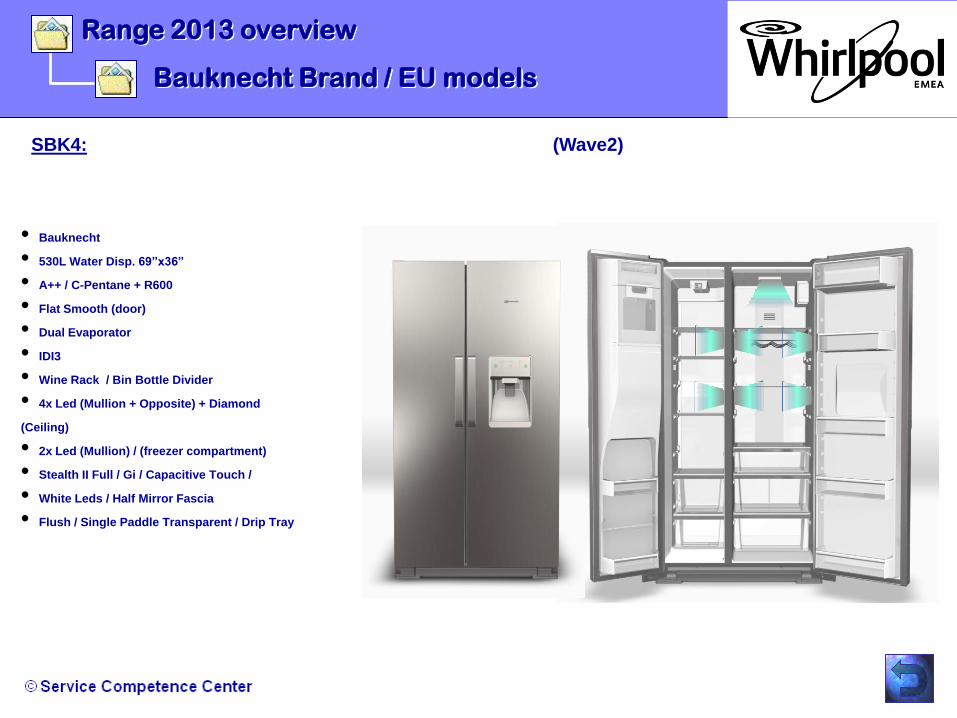
SBK4: (Wave2)
•Bauknecht
•530L Water Disp. 69”x36”
•A++ / C-Pentane + R600
•Flat Smooth (door)
•Dual Evaporator
•IDI3
•Wine Rack / Bin Bottle Divider
•4x Led (Mullion + Opposite) + Diamond
(Ceiling)
•2x Led (Mullion) / (freezer compartment)
•Stealth II Full / Gi / Capacitive Touch /
•White Leds / Half Mirror Fascia
•Flush / Single Paddle Transparent / Drip Tray

- Stealth UI application overview
- Dispensing Models / Connectors
- Non-Dispensing Models / Connectors
- Key Assignment & Functions: Dispenser Models
- Key Combination: Dispenser Models
- Key Assignment & Functions: Non-Dispenser
- Key Combination: Non-Dispenser Models
- General description of the User Interface
- Control System
- Minotaur Core Board / Block Diagrams
- Minotaur Core Board / Connector Locations
Operations

Operation
Stealth UI application overview
The Stealth User Interface Board will be responsible for the following actions:
•Drive the Ice Door Stepper Motor (only Dispenser Model with IDI).
•Read 6 capacitive touch switches or tactile switches.
•Drive LED dispenser Lighting.
•Drive dispenser housing heater (only Dispenser Model with IDI).
•Drive Fill tube heater if applicable (only Dispenser Model with IDI).
•Drive RC door heater (only Dispenser Model with IDI).
•Read Ice/water Pad (1 pad) switch (only Dispenser Model with IDI).
•Facilitate ice dispensing (cubed/crushed) with the core Control Board (only Dispenser Model with IDI)
•Facilitate water dispense with the core Control Board (only Dispenser Model with IDI).
•Drive LED drivers
•Read 6 capacitive touch switches or tactile switches.
•Drive Chimes for audible feedback of key presses, error conditions, and events;
•Communicate with the Core Board (Minotaur)
•Board-level flash-programmable;
•Store the user settings in non-volatile memory (EEPROM);
•Configuration values stored in Flash memory
•Facilitate temperature Control
•Manufacturing mode
•Service mode
•„Stealth“ User
Interface

Operation
Dispensing Models / Connectors
•J
3
•J
5
•J
6
•J
10
•J
2
•J
1
•J
7
•J
9
Connector Pin / Description
J1
1 Ice Pad Source
2 Ice Pad In
3 Not Used
4 Not connected
J2
1 Fill tube heater, Source
2 Not used
3 Dispenser housing heater, Source
4 +14 Vdc (WIDE)
5 Data (WIDE)
6 GND (WIDE)
7 Stepper Motor (+14Vdc)
8 Fill tube heater, Return
9 Not used
10 Dispenser housing heater, Return
11 Stepper Motor LA
12 Stepper Motor LB
13 Stepper Motor LC
14 Stepper Motor LD
J3
1 Not used
2 Not used
3 Not used
4 Not connected
J5
1 Not used
2 Not used
3 Not used
4 Not used
5 Not used
J6
1 Dispenser light, Source
2 Not connected
3 Dispenser light, Return
J7
1 Swim
2 +5V DC
3 Reset_Active_Low
4 Ground
J9
1 +5Vdc
2 Ground
3 Timer_Reset
4 In_Circuit_Program_Clock
5 In_Circuit_Program_Data
J10
1 Not used
2 Not used
3 Not used
4 Not used

Operation
Non-Dispensing Models / Connectors
•J
3
•J
5
•J
6
•J
10
•J
2
•J
1
•J
7
•J
9
Connector Pin / Description
J1
1 Not used
2 Not used
3 Not used
4 Not connected
J2
1 Not used
2 Not used
3 Not used
4 Not used
5 Not used
6 Not used
7 Not used
8 Not used
9 Not used
10 Not used
11 Not used
12 Not used
13 Not used
14 Not used
J3
1 Not used
2 Not used
3 Not used
4 Not connected
J50
1 +14Vdc (WIDE)
2 Data (WIDE)
3 Ground (WIDE)
4 Not used
5 Not used
J6
1 Not used
2 Not connected
3 Not used
J7
1 Swim
2 +5Vdc
3 Reset_Active_Low
4 Ground
J9
1 +5Vdc
2 Ground
3 Timer_Reset
4 In_Circuit_Program_Clock
5 In_Circuit_Program_Data
J10
1 Not used
2 Not used
3 Not used
4 Not used

Operation
Key Assignment & Functions: Dispenser Models
Control Key Description Method
Key no. Label
SW1 FREEZER Temperature setting of FC Short Press
SW2
FAST FREEZING To activate / deactivate fast freezing Short Press
ICE DISPENSING ON/OFF To switch Ice Dispense ON/OFF Long Press
3Secs
SW3 ICE/WATER Selection of water/crushed ice/cubed ice Short Press
SW4
RESET ALARM
To RESET the sound alarms(Power Fail Alarm & Door Open
Alarm)
Short Press
To RESET the general alarms
(WFI & AFI)
Long Press 3
secs
ICE MAKER TEST FOR MANUFACTURING
TESTING
To enable Ice making water fill and Ice maker harvesting cycle
within first 2 min of power ON and in Cooling Off mode.
Long Press 3
secs
SW5 VACATION MODE To activate/deactivate vacation mode Short Press
SW6 REFRIGERATOR Temperature setting of RC Short Press

Operation
Key Combination: Dispenser Models
KEY COMBINATION OR SEQUENCE
WHIRLPOOL (ASIA )
ENTRY Ice /Water (Key 3) & Reset Alarm (KEY4)Long Press
3secs
EXIT Ice /Water (Key3) & Reset Alarm (Key4)Long Press
3secs
Freezer(Key1) & Fast freezing(Key2),
Recycle power
20minutes timeout
ENTRY Vacation key( Key5) & RC Temp ( Key 6)Long press
3secs
EXIT Vacation key( Key5) & RC Temp ( Key 6)Long press
3secs
Step #1: Open and Close the RC door after 10 sec from
Power On.
Step #2: Cooling OFF key (Key5 & Key 6) within 10 sec after
step # 1 is completed.
Everything shall happen within 1 minute after the product Power
Up. After 1 minute this mode shall not be accessible until the
next Product Power Up;
Cooling Off sequence (Key5 & key6)
Recycle power
Time out=5minuts;
Last step of manufacturing mode.
Short key
Press
ENTRY
Sequence
EXIT
FINAL
ELECTRCIAL
TEST
Long press
3secs
METHOD
KEY LOCK
SERVICE
MODE
ENTRY Freezer(Key1) & Fast freezing(Key2)Long Press
3secs
EXITLong Press
3secs
COOLING OFF
FEATURE ACTION

Operation
Key Assignment & Functions: Non Dispenser
Control Key Description Method
Key # Label
SW1 FREEZER Temperature setting of FC Short Press
SW2 FAST FREEZING To activate / deactivate fast freezing Short Press
SW3 ECO ENERGY Set points will be energy efficient Short Press
SW4 RESET ALARM
To RESET the sound alarms(Power Fail Alarm & Door Open Alarm) Short Press
To RESET the general alarms ( AFI).For all models.
To RESET the general alarms (AFI).For SUK1.NP & SW2.NP models. Long Press 3 secs
SW5 VACATION MODE To activate/deactivate vacation mode Short Press
SW6 REFRIGERATOR Temperature setting of RC Short Press

Operation
Key Combination: Non-Dispenser Models
1 or 2, KEY COMBINATION
WHIRLPOOL (ASIA )
Freezer(Key1) & Fast Freezing (Key2)
At power fail/ interrupt, 20minutes timeout
ENTRY Vacation key( Key5) & RC Temp (Key 6)Long press
3secs
EXIT Vacation key( Key5) & RC Temp (Key 6)Long press
3secs
Step #1: Open and Close the RC door after 10 sec from
Power ON
Step #2: Cooling OFF key (Key5 & Key 6) within 10 sec after
step # 1 is completed
Everything shall happen within 1 minute after the product Power
Up. After 1 minute this mode shall not be accessible until the
next Product Power Up;
Cooling Off sequence (Key5 & Key 6)
Recycle power
Time out=5minuts;
Last step of manufacturing mode.
SERVICE
MODE
Freezer(Key1) & Fast Freezing (Key2)
FEATURE ACTION METHOD
KEY LOCK
ENTRY ECO energy(Key3) & Reset Alarm (Key4)Long Press
3secs
EXIT ECO energy(Key3) & Reset Alarm (Key4)Long Press
3secs
FINAL
ELECTRICAL
TEST
Short Key
Press
ENTRY
Sequence
Long Press
3secs
EXITLong Press
3secs
COOLING OFF
Long Press
3secsEXIT
ENTRY
NOTE:
Any long key press (requires 3 seconds of press and hold) cannot be interrupted during the 3 seconds countdown.
If user presses another key or paddle during the 3 seconds countdown, user needs to release the key and press it
again to start the countdown.

•1st button controls the
temperature in the freezer
compartment
•(-14 to -24 C)
•2nd button activated/deactivates the
•Fast Freezing mode (thermometer icon)
•3rd button activates the most
•energy efficient temperatures
•in the FC/RC compartments
•simultaneously (-14/6 C)
•4th button* resets all
alarms and postpones the
sound alert which is
activated when a door is
held open for too long.
•5th button activated/deactivates the
•Vacation mode (parasol icon).
•6th button controls the
temperature in
•the refrigerator
compartment (1 to 6 C).
Operation
General description of the User Interface
“Stealth” User Interface No Dispenser Model / Interface Controls:
•The Stealth “No Dispenser” interface is controlled by 6 capacitive touch/tactile buttons.
•The Eco Energy and Reset Alarm buttons can be pressed simultaneously for 3 seconds in order to activate the Key Lock.
•(If another button is pressed while this action is being taken, both actions will be terminated)
•The temperature buttons do not require continuous scrolling if the button is kept pressed.

Operation
General description of the User Interface
“Stealth” User Interface Single Paddle Model / Interface Controls:
•The Stealth “Single Paddle” interface is controlled by 6 capacitive touch/tactile buttons.
•The Ice Selection and Reset Alarm buttons can be pressed simultaneously for 3 seconds in order to activate the Key Lock.
•(If another button is pressed while this action is being taken, both actions will be terminated)
•The temperature buttons do not require continuous scrolling if the button is kept pressed.
•1st button controls the
temperature in the freezer
compartment
•(-14 to -24 C)
•3rd button
sets
•ice & water
type
•4th button* resets all
alarms and postpones the
sound alert which is
activated when a door is
held open for too long.
•5th button activated/deactivates the
•Vacation mode (parasol icon).
•6th button controls the
temperature in
•the refrigerator
compartment (1 to 6 C).
•2nd button activated/deactivates the Fast
Freezing mode (thermometer icon). IF kept pressed
for 3 seconds, the ICE DISPENSING is
disabled/enabled.

•Power Failure Alarm is
visible when there has been
a power failure & the
temperature has increased >
X C
•Digits give feedback of the set
•temperature in the refrigerator
•1 to 6 C in normal mode,
•Symbol is visible when cooling is On.
•If cooling is switched Off, this central
•compartment symbol will not be visible.
•General Alarm icon is visible
•when the appliance is in an
•alarm state.
•Antibacterial Filter icon is
visible when
•the filter will need replacing
soon (amber)
•and when it needs replacing
(red)
Vacation icon is visible when
•the Vacation mode is
active.
•(Remains active until the
user
•deactivates the mode).
•6 Sense icon is
always visible when
cooling is on (fixed
light).
•Key Lock icon is visible
•when the Key Lock is active
•Icon is visible when the
refrigarator temperature is set
to 6 C which is the most
energy efficient setting.
•Door open icon
is
•visible when a
door is open
•Gravity filter
indication
•Icon is visible when the
freezer
•temperature is set to -14 C
which is the most energy
efficient setting.
•Digits give feedback of the set
•temperature in the freezer
•(-14 to -24 C)
•Fast Freezing icon is
visible
•when the Fast Freezing
mode is active. Switches Off
automatically after 24h
Operation
Stealth No Dispenser Model / Display Segments:
•The illustration below shows all display segments which have been foreseen for the European Stealth control with No
Dispenser.
General description of the User Interface

•Power Failure Alarm is
visible when there has been
a power failure & the
temperature has increased >
X C
•Digits give feedback of the set
•temperature in the refrigerator
•1 to 6 C in normal mode,
Water glass icon (always On)
with indications of what
products that are set to be
dispensed:
•A: Still water / B: Crushed
ice / C: Cubed ice
•General Alarm icon is visible
•when the appliance is in an
•alarm state.
•Antibacterial Filter icon is
visible when
•the filter will need replacing
soon (amber)
•and when it needs replacing
(red)
Vacation icon is visible when
•the Vacation mode is
active.
•(Remains active until the
user
•deactivates the mode).
•6 Sense icon is
always visible when
cooling is on (fixed
light).
•Key Lock icon is visible
•when the Key Lock is active
•Icon is visible when the
refrigarator temperature is set
to 6 C which is the most
energy efficient setting.
•Door open icon
is
•visible when a
door is open for
more than 2
minutes.
•Icon is visible when the
freezer
•temperature is set to -14 C
which is the most energy
efficient setting.
•Digits give feedback of the set
•temperature in the freezer
•(-14 to -24 C)
•Fast Freezing icon is
visible
•when the Fast Freezing
mode is active. Switches Off
automatically after 24h.
Operation
Stealth Single Paddle Model / Display Segments:
•The illustration below shows all display segments which have been foreseen for the European Stealth control with Dispenser.
General description of the User Interface
•Water Filter icon is visible when the filter will need
•replacing soon (amber) and when it needs replacing
(red)
•ICE
OFF
symbol
•A
•B
•C

Operation
General description of the User Interface
Stealth No Dispenser Model & Single Paddle Model / Functional Content:
•Temperature Control:
•1. Individual Temperature setting of Refrigerator -> Temperature range 1 to 6 C (set in steps of 1 C)
2. Individual Temperature setting of Freezer -> Temperature range -14 to -24 (set in steps of 1 C)
•3. Vacation Mode -> Sets the refrigerator to the values as per the flash map table , while freezer compartment
• temperature remains unchanged.
•4. Fast Freezing Mode -> Compressor works at full power for 24 hours. Freezer Compartment Temp. displayed: -24°C.
•Other:
•1. Refrigerator/Freezer Cooling Off -> Switches off cooling in both compartments (also compartment light is disabled)
2. Key Lock -> Disables all buttons. Only possible interaction is the deactivation procedure.
•3. 6th Sense active -> Icon is always visible when cooling is on(fixed).
Alarms / Notifications:
•1. Eco Energy Feedback -> Icons lit when FC/RC has most energy efficient temp settings (-14/6 C).
•2. Eco Energy direct access button -> Button which sets the most energy efficient temperatures simultaneously in the
• Freezer- and Refrigerator compartments (-14/6 C).
•3. Refrigerator/Freezer Door Open -> Visual indication when refrigerator/freezer door is open.
•4. Refrigerator/Freezer Door Open Alarm -> Visual and Audio feedback when door has been open for 2 minutes.
•5. General Alarm -> Appears when there is an alarm state.
•6. Power Failure Alarm -> Indication when there has been a Power Failure.
•7. Antibacterial Filter needs Replacing Soon -> Reminder to purchase new filter (amber light).
•8. Antibacterial filter needs Replacing -> Notification that Antibacterial filter needs to be replaced (red light).
•Dispenser Functions:
•1. Still Water selected -> Indication when Still Water is set to be dispensed.
•2. Ice Cube selected -> Indication when Ice Cubes is set to be dispensed.
•3. Crushed Ice selected -> Indication when Crushed Ice is set to be dispensed.

Operation
General description of the User Interface
Stealth No Dispenser Model & Single Paddle Model / Filter Data:
•Filter Life
GOOD
•ORDER
•REPLACE •G
FI
•UI Symbol Colour
•- (blank)
•Amber
•Red
•Time Usage (Days)
•0 to 100
•101 to 119
•120+
•A
FI
•Filter Life
GOOD
•ORDER
•REPLACE
•UI Symbol Colour
- (blank)
•Amber
•Red
•Time Usage (Days)
0 to 120
•121 to 180
•181+
Gravity Filter Indication (sand filter):
Antibacterial Filter Indication:
•Stage name
•GOOD
•ORDER
•REPLACE
•Replace Overdue
•W
FI
•Water Usage
•0 to 165,99 Gallons / 0 to 625 litre
•166 to 199,99 Gallons / 626 to 757
litre
•200+ Gallons / 758 + litre
•NA
•Time Usage (Days)
•0 to 149
•150 to 181
•182+
•After 14 days at REPLACE
Water Filter Indication:
Operation
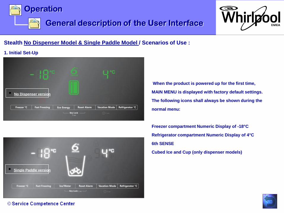
Stealth No Dispenser Model & Single Paddle Model / Scenarios of Use :
1. Initial Set-Up
General description of the User Interface
When the product is powered up for the first time,
MAIN MENU is displayed with factory default settings.
The following icons shall always be shown during the
normal menu:
Freezer compartment Numeric Display of -18°C
Refrigerator compartment Numeric Display of 4°C
6th SENSE
Cubed Ice and Cup (only dispenser models)
•Single Paddle version
•No Dispenser version

Operation
Stealth No Dispenser Model & Single Paddle Model / Scenarios of Use :
2. Changing the Freezer Temperature
General description of the User Interface
In order to adjust the Freezer temperature, the user presses
the FREEZER Key. A “ Key Press “ chime will be produced
for every key press.
The temperature readout instantly changes the values
cyclic loop in the following direction (start value taken from
the example to the left) :(-14, -15, -16,-17,-18,-19,-20, -21,
-22, -23, -24, -14, -15°C etc…
Whenever user selects -14°C, FC ECO INDICATION icon
will turn ON , as its most energy efficient temperature.
During this operation, the fridge set point will remain
the same.
New FC set point will send to core control immediately
upon change. If the Key is press & hold, slew is not allowed.
The temperature set point will change once.

Operation
Stealth No Dispenser Model & Single Paddle Model / Scenarios of Use :
3. Changing the Refrigerator Temperature:
General description of the User Interface
In order to adjust the Refrigerator temperature, the
user presses the FRIDGE DEGREE C key.
A “Key Press“ chime will be produced for every key
press.
The temperature readout instantly changes the values
cyclic loop in the following directio
(Start value taken from the example to the left)
5, 6, 1, 2, 3, 4, 5, 6°C etc…
Whenever user selects 6°C, RC ECO INDICATION icon
will turn ON , as its most energy efficient temperature.
The Freezer set point will remain the same.
New Fridge set point will send to core control
immediately upon change.
If the Key is press & hold, slew is not allowed.
The temperature set point will change once.

Operation
Stealth No Dispenser Model / Scenarios of Use :
4.0 Activating Fast Freezing
General description of the User Interface
Pressing FAST FREEZING key activates/deactivates the fast
ice feature. An “Engage “chime is produced.
FAST FREEZING icon is lit and the function is activated.
The Freezer temperature changes to -24°C on UI display.
Fast Freeze can be activated in normal menu.
If power is interrupted, Fast Freeze will retrieve from
EEPROM and resume. There will be 30 second delay for
any set point changes to write to EEPROM.
During Fast Freeze mode, changes to the Fridge
temperature set point can be made.
FAST FREEZING DEACTIVATION:
Fast freezing is automatically deactivated after a
Power Outage Alarm.
Fast Freezing can also be deactivated if the user:
Presses the FREEZER DEGREE key.

Operation
Stealth No Dispenser Model / Scenarios of Use :
4.1 Activating Fast Freezing
General description of the User Interface
Presses the FAST FREEZING key - the Fast freezing mode
will be deactivated and the Freezer will resume the same
temperature as it had when Fast freezing was activated. i.e
between -14 to -24°C . A “Disengage “chime is produced.
- Switched Cooling Off will produce “Power Off” chime
(switches off cooling in both Fridge and Freezer
compartment).
- Using ECO ENERGY key, the fast freezing can be exit &
the Freezer temperature be set to -14°C. A “Engage”
chime is produced.
- Factory default Fast Freeze mode is OFF.
- Inhibit Defrost Time in Fast freeze mode is 2-hour
(Defrost time will be configured in flash map).

- Pressing FAST FREEZING key activates/deactivates the fast ice
feature. An “Engage “chime is produced. FAST FREEZING
icon is lit and the function is activated. The FC temperature
changes to -24°C on UI display.
- Fast Freeze can be activated in Normal menu and the feature
lasts for 24 hours. If power is interrupted, Fast Freeze shall
retrieve from EEPROM and resume. There will be 30 second
delay for any set point changes to write to EEPROM.
- Fast freezing is automatically deactivated after a Power
Outage Alarm.
- Fast Freezing can also be deactivated if the user:
1. Presses the Freezer Compartment degree key (First press
makes the Freezer compartment resume the same temperature
,setting as it had when Fast freezing was activated i.g. between
-14 to -24°C.
2. Presses the FAST FREEZING key - the Fast freezing mode will
be deactivated and the Freezer Compartment will resume the
same temperature as it had when Fast freezing was activated.
3. Switched Cooling OFF will produce “Power Off” chime
(switches OFF cooling in the fridge & freezer compartment).
Operation
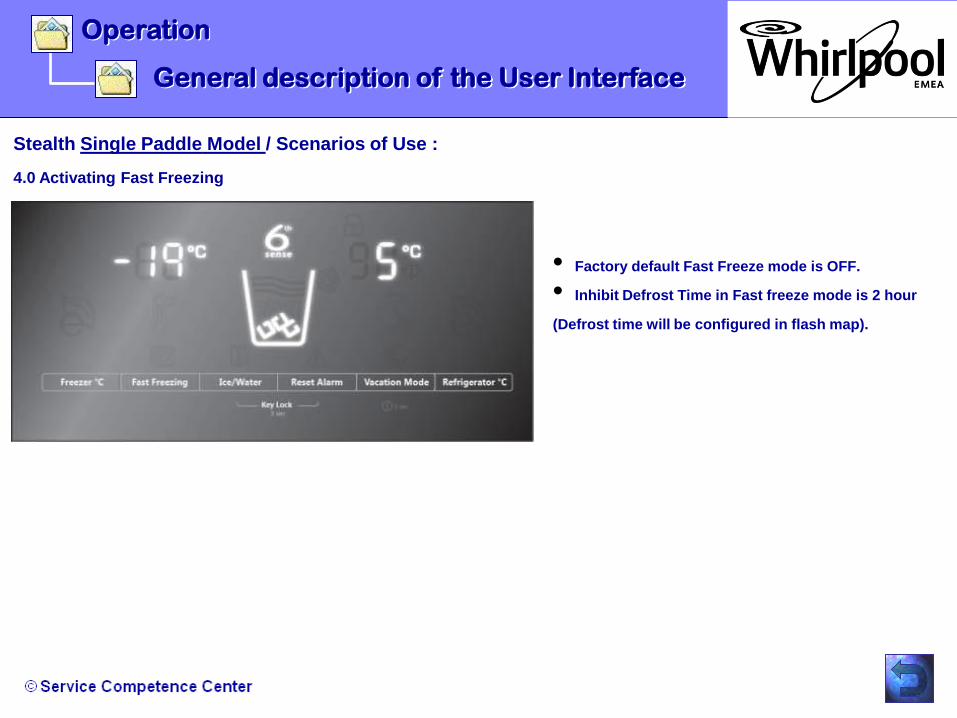
Stealth Single Paddle Model / Scenarios of Use :
4.0 Activating Fast Freezing
General description of the User Interface
Operation
Stealth Single Paddle Model / Scenarios of Use :
4.0 Activating Fast Freezing
General description of the User Interface
•Factory default Fast Freeze mode is OFF.
•Inhibit Defrost Time in Fast freeze mode is 2 hour
(Defrost time will be configured in flash map).
Operation
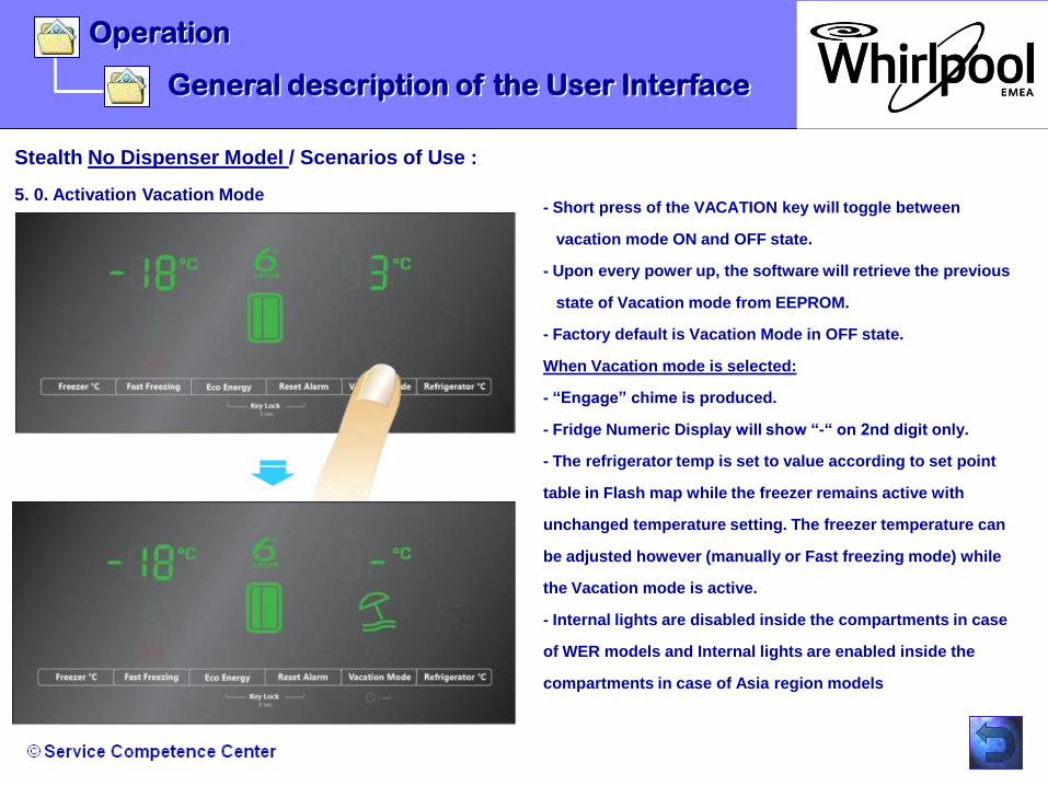
Stealth No Dispenser Model / Scenarios of Use :
5. 0. Activation Vacation Mode
General description of the User Interface
- Short press of the VACATION key will toggle between
vacation mode ON and OFF state.
- Upon every power up, the software will retrieve the previous
state of Vacation mode from EEPROM.
- Factory default is Vacation Mode in OFF state.
When Vacation mode is selected:
- “Engage” chime is produced.
- Fridge Numeric Display will show “-“ on 2nd digit only.
- The refrigerator temp is set to value according to set point
table in Flash map while the freezer remains active with
unchanged temperature setting. The freezer temperature can
be adjusted however (manually or Fast freezing mode) while
the Vacation mode is active.
- Internal lights are disabled inside the compartments in case
of WER models and Internal lights are enabled inside the
compartments in case of Asia region models

- If there is an alarm condition during Vacation mode,
pressing the RESET ALARM key will reset the alarm.
Refer to the appropriate alarm section for behaviours.
The vacation mode can be deactivated in 4 ways:
•1. By pressing the Vacation Mode key makes the Fridge
resume the same temperature setting as it had when the
Vacation Mode was activated. Disengage chime is produced.
•2. By pressing the Refrigerator °C key - first press makes the
Fridge resume the same temperature setting as it had when the
Vacation Mode was activated. Key press chime is produced.
•3. By switching Cooling OFF - switch OFF both Fridge and
Freezer cooling completely. Power OFF chime is produced.
Vacation mode is deactivated and previous Fridge setting (the
one used before the vacation mode was activated) is restored .
•4. By pressing the Eco Energy key - the vacation mode will
be deactivated and the Fridge temperature be set to 6°C.
Freezer setting will be change to -14°C . Engage key chime is
produced.
Operation
Stealth No Dispenser Model / Scenarios of Use :
5.1. Activation Vacation Mode
General description of the User Interface

Operation
Stealth Single Paddle Model / Scenarios of Use :
5. 0. Activation Vacation Mode
General description of the User Interface
- Short press of the VACATION key will toggle between vacation
mode on and off state.
- Upon every power up, the software will retrieve the previous state
of Vacation mode from EEPROM.
- Factory default is Vacation Mode in off state.
- When Vacation mode is selected:
1. “Engage” chime is produced.
2. The VACATION icon is on and WATER/CRUSHED
ICE/CUBED ICE is disabled . RC NUMERIC DISPLAY will show “-“
on 2nd digit only.
3. The refrigerator temp is set to value according to set point table
in FLASH map settings while the freezer remains active with
unchanged temperature setting. The freezer temperature can be
adjusted however (manually or Fast freezing mode) while the
Vacation mode is active.
- Internal lights are disabled inside the compartments.
4. Dispenser is disabled and dispenser light is off.
If ICE/WATER key or paddle is pressed, “invalid” chime is
produced twice synchronizing with blinking o f VACATION icon.

- If there is an alarm condition during Vacation mode, pressing the
RESET ALARM key will reset the alarm.
- The vacation mode can be deactivated in 3 ways (For dispensing
application):
1. By pressing the Vacation Mode key makes the RC resume the
same temperature setting as it had when the Vacation Mode was
activated. Disengage chime is produced.
2. By pressing the Refrigerator °C key - first press makes the
fridge compartment resume the same temperature setting as it had
when the Vacation Mode was activated. Key press chime is
produced.
3. By switching Cooling OFF - switch off both fridge and
freezer cooling completely. Power off chime is produced.
- Vacation mode is deactivated and previous fridge setting has been
restored (the one used before the vacation mode was activated).
The dispenser can be used (for dispensing application) and the light
inside both compartments is active. The dispenser light will also be
active.
Operation
Stealth Single Paddle Model / Scenarios of Use :
5. 0. Activation Vacation Mode
General description of the User Interface

Operation
Stealth No Dispenser Model & Single Paddle Model / Scenarios of Use :
6.0. Activating Key Lock
General description of the User Interface
ACTIVATING KEY LOCK
- When lock key combination is pressed and hold for 3 second.
After 3 second, UI will be locked and LOCK icon is turned ON on
normal menu. An “Engage” chime is produced.
- If lock key combination released before 3 seconds, invalid key
chime will be produced 2 times. During 3 second, if any other key
is pressed, both actions (lock key combination & next key
pressed) will terminate and invalid key chime will produced 2
times.
- When the Key Lock is activated, no key or key combination is
allowed .
- If any other key is pressed, while the Key Lock is set, the LOCK
icon will flash quickly 2 times (0.5 sec ON, 0.5sec OFF x 2
times) synchronized with “ invalid key” chime ( x 2 times)

Operation
Stealth No Dispenser Model & Single Paddle Model / Scenarios of Use :
6. 1. Activating Key Lock
General description of the User Interface
DEACTIVATING KEY LOCK
- To Unlock the UI, long press of lock key combination made
simultaneously.
- A “Disengage” chime is produced. The LOCK icon will blink
during the 3 second press and hold then turn OFF at end of 3
seconds. If lock key combination released before 3 seconds,
invalid key chime will be produced 2 times and the lock icon will
blink 2 times.
- When the UI is locked, if any other Alarm LED icons i.e. Door
ajar, WFI, AFI is activated, the specific icon should be turned ON
and chimes / blinking pattern as applicable should be played.
Pressing Alarm Reset key will give invalid chime x2 and lock icon
will flash twice. If power outage alarm is active, pressing Alarm
Reset key will reset power outage alarm and return to
LOCK menu.

Operation
Stealth No Dispenser Model & Single Paddle Model / Scenarios of Use :
7.0. Opening the Refrigerator/Freezer Door
General description of the User Interface
Door Open Condition :
When the door(s) is(are) open, the DOOR OPEN icon is lit
continuously through out the door open duration. When the
door(s) is(are) closed, the DOOR OPEN icon will switch off.
Door Ajar Alarm Condition:
When the door(s) is(are) kept open for 2 minutes, the Door Ajar
Alarm condition is entered. The GENERAL ALARM icon will
come on solid and stay on while in the Door Ajar Alarm
condition.
ALERT chime shall be produced 3 times and repeated after
every 10 sec until reset while synchronized with 7 blinking of
the door open icon and door open icon stays on after the
blinking.

For the other menus, door ajar alarm shall work as follows:
MAIN MENU: The UI shall stay in MAIN MENU and resume door
ajar alarm condition.
LOCK MENU: The UI shall stay in LOCK MENU and resume door
ajar alarm condition.
SLEEP MENU: The UI will wake up and display door ajar icon
while in either MAIN MENU or LOCK MENU (which ever one
selected prior to sleep).
Since the door alarm condition will wake up the UI every 2 min,
this will prevent the UI from ever going back into sleep mode.
COOLING OFF MENU: The UI stays in COOLING OFF MENU,
door ajar alarm is disabled. If door was open and cooling is
turned off, when cooling is turned back on, the door ajar alarm
timer will reset. Pressing the RESET ALARM key will snooze the
alarm sound but the door open alarm icons will remain visible
until the door is closed. Refer to Alarm Reset section later on
the document.
Operation
Stealth No Dispenser Model & Single Paddle Model / Scenarios of Use :
7.1. Opening the Refrigerator/Freezer Door
General description of the User Interface

Operation
Stealth No Dispenser Model & Single Paddle Model / Scenarios of Use :
7.2. Opening the Refrigerator/Freezer Door
General description of the User Interface
The visual alarm indications will remain until the door has been
closed however (door open symbol is On or flashing).
If the user does not close the door within 2 minutes, the sound
alert will reoccur as a safety measure. If the door has been
opened for more than 2 minutes and the user presses the Reset
button, the alarm sound will Snoozed, the door open icon will
remain On, until the user closes the door and re-open OR power
ON/OFF the product.
If cooling is Off, the door icon is disabled, and the door ajar
alarm will is disabled.
There are two ways to reset the door ajar condition is by closing
the doors or resetting power to the unit. If the user wishes to
keep the door open even though the alarm is activated (for
cleaning up spilled food for example), he/she can press the
Reset Alarm button and the sound alarm will be snoozed (10 sec
On ,10 se OFF) for next 2 min till the door is closed.

•SLEEP / IDLE MODE:-
•UI will not go into sleep mode while the Power Outage Alarm is visible, or in cooling off mode, or while either door is in ajar.
•Entering sleep mode :
•User inactivity for 2 minutes at MAIN MENU or LOCK MENU will enter into sleep mode. In the SLEEP MENU the 6TH SENSE and
COMPARTMENT icons will change from 100% brightness to 25% brightness. All other icons will be off. No chimes at entering sleep
mode.
Waking up sleep mode:
•Waking up conditions - Any key press or either door opening Waking by key press – UI wakes up at first key press, but no action
taken for key press. At second key press, the key function is activated. Waking by key press, if UI is locked – UI wakes up at first key
press but no action taken for key press. Lock mode will be entered. Waking by key press and hold combination – UI wakes up and
goes to the corresponding menu for that key combination. Waking by door open – if either door is open, UI wakes up with the
appropriate door icon light up. No chimes at UI wakeup.
•Menu transition from sleep mode:
•If UI is locked, menu transitions from sleep mode to LOCK MENU
•If UI is unlocked, menu transitions from sleep mode to MAIN MENU
Operation
Stealth No Dispenser Model & Single Paddle Model / Scenarios of Use :
7.3. Opening the Refrigerator/Freezer Door
General description of the User Interface

ACTIVATING ECO ENERGY:
- Pressing ECO ENERGY key sets the most energy efficient
temperature setting (-14 C for FC & 6 C for RC) &the Eco Energy
symbols appear.
DEACTIVATING ECO ENERGY:
- If the user changes the set temperature from the Eco Energy set
point, the symbol will simply switch off.
- By pressing the ECO ENERGY key a 2nd time(deactivating eco
energy mode), the temperature settings will return to the set
points they had before the key was pressed the 1st time.
A “Disengage” chime is produced.
- In ECO energy mode, if Freezer DEGREE key is pressed, Freezer
ECO INDICATION icon will turn off & “disengage” chime is
produced. Freezer temperature is decrement by one value.
Fridge temperature will remain same as 6 C, which is a new set
point value. ECO Energy mode is exited.
- There is one symbol for each compartment, so that if only 1 of the
2 compartment has the most energy efficient Temperature set,
only the symbol belonging to that compartment will be lit.
An “Engage” key chime is produced.
Operation
Stealth No Dispenser Model / Scenarios of Use :
8.0. The Eco Energy Feedback & Direct Access Button
General description of the User Interface
•“Eco Energy” temperature set in both compartments:
Operation
Stealth No Dispenser Model / Scenarios of Use :
8.1. The Eco Energy Feedback & Direct Access Button
General description of the User Interface
- In ECO energy mode, if RC DEGREE key is pressed, RC ECO INDICATION icon will turn off & “disengage” chime is produced.
Fridge temperature is increment by one value. Freezer temperature will remain same as -14°C , which is a new set point value.
ECO Energy mode is exited.
- In ECO mode, if FAST FREEZING key is pressed, Freezer ECO INDICATION icon will turn OFF and will enter into fast freezing
mode with “engage” chime. There is no “disengage” chime during exit of ECO mode.,
- In ECO mode, if VACATION key is pressed, Fridge ECO INDICATION icon will turn OFF and will enter into vacation mode with
“engage” chime. There is no “disengage” chime, during exit of ECO mode.

Operation
General description of the User Interface
Stealth Dispenser Model / Scenarios of Use :
9. Changing the Dispenser Setting
- Dispenser is mounted on the freezer door
- Regular valves is used
- Pressing the ICE/WATER key selects between the Water / Crushed Ice /
Ice Cubes options in sequence. An ENGAGE chime is produced for
each selection. This selection will have cyclic continuous loop.
- Factory default setting for the ICE/WATER key is “Ice Cubes”.
- After dispensing timeout (Water dispensing times out in 5 minutes and
Ice dispensing times out in 10 minutes), dispensing will stop and
“INVALID” chime will be produced. If pads are not released more than 2
minutes after dispensing timeout, UI enters in Sleep mode. When the
pad is released, UI will wake up from Sleep mode with normal menu
without any chime
- If power fails/interrupts during Ice/water dispensing, ice/water
dispensing will disable . To allow dispensing again, release paddle and
power outage alarm must be reset.
- If communication fails, dispensing will not be allowed.
- During the dispensing process, only the selected dispensing product
icon (WATER / CUBED ICE / CRUSH ICE icon) will be displayed within
the CUP icon segment. Other LED icons behavior will not change.

Operation
General description of the User Interface
Stealth Dispenser Model / Scenarios of Use :
10. Dispensing Ice & Water
To dispense Ice or Water, the user presses a container against the paddle. The selected product (depending on setting in display)
will be dispensed until the user removes the container from the paddle. Water Dispensing can only be done for 5 minutes and Ice
Dispensing can be done for 10 minutes continuously. After that, dispensing will be automatically stopped & the sound “invalid“
will be played. The product which is being dispensed should be the only product visible during the dispensing phase and be lit
(fixed light) at 100% brightness.
If the user tries to dispense while the product is in Vacation mode, the invalid key press sound will be played twice synchronized
with the of blinking of the vacation symbol.
If the user tries to dispense while the product is showing the Power Outage alarm, the invalid key press sound will be played twice
synchronized with the blinking of the power outage symbol.
When pressing the Ice/Water button, the segments will be lit in the following order;
•Water •Crushed Ice •Ice Cube •Water (continuous loop)

Operation
General description of the User Interface
Stealth Dispenser Model / Scenarios of Use :
11. Idle menu/Sleep mode, Dispensing
- UI will not go into sleep mode while the Power Outage Alarm is visible, or while in cooling off mode, or while either compartment door is ajar.
- Entering sleep mode (Dispensing):
User inactivity for 2 minutes at MAIN MENU or LOCK MENU will enter into sleep mode. In the SLEEP MENU the 6th SENSE, CUP and
WATER/CRUSH ICE/CUBED ICE icons will change from 100% brightness to 25% brightness. AFI & WFI icons will also change the brightness
from 100 % to 25 % if active. Dispenser light will remain visible at 25% brightness. All other icons will be off ,except for AFI & WFI alarms.
- No chimes at entering sleep mode.
Waking up sleep mode:
Waking up conditions - Any key press or either door opening
•Waking by key press – UI wakes up at first key press, but no action taken for key press. At second key press, the key function is activated.
•Waking by key press, if UI is locked – UI wakes up at first key press but no action taken for key press. Lock mode will be entered. Waking by
key press and hold combination – UI wakes up and goes to the corresponding menu for that key combination.
•Waking by door open – if either door is open, UI wakes up with the appropriate door icon light up. No chimes at UI wakeup.
•Menu transition from sleep mode:
•If UI is locked, menu transitions from sleep mode to LOCK MENU
•If UI is unlocked, menu transitions from sleep mode to MAIN MENU

A) To disable the icemaker, the user must keep the second Button
(Fast Freezing) pressed for 3 seconds.
When this action has been taken, the “Disengage” sound is produced
and the “ICE OFF” symbol will appear above the Freezer digits.
B) When the icemaker is disabled, no ice can be dispensed and ice
production (harvesting) is disabled.
As the user presses the Ice/Water button, the ice symbols will never be
shown & the water segments remains constantly lit.
If the user tries to set an ice type by pressing the Ice/Water button, the
“Invalid Key press” sound is produced 2 times & the “ICE OFF”
symbol flashes will blink 2 times.
The ice maker is reactivated by keeping the second button (FAST
FREEZING) pressed for 3 seconds. During these 3 seconds, the "Ice Off“
symbol will blink 3 times. When this action is taken, the “Engage” sound
is produced and the “ICE OFF” symbol is switched off. The water
remains as the preset Product to dispense, but the user can now press
the Ice/Water button to change product.
C) If during “ICE OFF” condition, power failure occurs , when the power
resumes back ,the system will go back in the Previous
condition “ICE OFF” mode.
Operation
General description of the User Interface
Stealth Dispenser Model / Scenarios of Use :
12. Ice OFF

Antibacterial filter indication is available in MAIN MENU and
LOCK MENU
At Order Stage: The AFI ORDER amber led icon will turn on (no
flashing and no beep occur at the MAIN MENU or LOCK
MENU).If RESET ALARM key is pressed to reset the air filter
indication, “invalid” chime is produced.
At Replace Stage: The AFI REPLACE red led icon will turn on
(no flashing). An alert chime is also activated. The Replace filter
Icon shall be activated all times while the UI is awake in MAIN
MENU and LOCK MENU. When the user has replaced the filter,
he/she presses the RESET key for 3 seconds to reset the alarm.
By doing so, the icon will be switched off. A “Disengage “chime
is produced once.
ORDER to REPLACE Transition: When stage change from
order to replace, an “alert” chime is produced. If the AFI status
changes from ORDER to REPLACE stage during sleep mode the
alert chime will be played as soon as the UI wakes up from
sleep mode.
Operation
Stealth No Dispenser Model / Alarms/Notifications:
1. Antibacterial Filter alarm
General description of the User Interface

Operation
Stealth Dispenser Model / Alarms/Notifications:
1.1. Water Filter alarm
General description of the User Interface
WFI indication is available in MAIN MENU and LOCK MENU
Dispensing and other menus are still functional during WFI Alarm
Depending to the Filter stage the UI shall work as follows:
At Order Stage: The WFI ORDER amber led icon will turn on (no
blinking and no beep occur at the MAIN MENU or LOCK MENU).
If RESET ALARM key is pressed to reset the water filter indication,
“invalid” chime is produced.
GOOD to ORDER Transition:
If the WFI status changes from GOOD to ORDER stage during
water dispensing, WFI ORDER amber led icon will blink 7 times
with Alert Chime sounded 3 times.
If the WFI status changes from GOOD to ORDER stage during ice
maker fill or due to time usage, WFI ORDER amber led icon will
blink 7 times with Alert Chime sounded 3 times at start of first
water dispense.

Operation
Stealth Dispenser Model / Alarms/Notifications:
1.1. Water Filter alarm
General description of the User Interface
•At Replace Stage:
•The WFI REPLACE red led icon will turn on. The icon will blink while dispensing water/Ice .The icon will blink from the beginning to
the end of dispensing. No sound will be produced. If RESET ALARM key is pressed to reset the water filter indication, “disengage” chime
is produced and the icon is turned off.
•ORDER to REPLACE Transition:
•If the WFI status changes from ORDER to REPLACE stage during water dispensing, WFI REPLACE red led icon will blink 7 times with
Alert Chime sounded 3 times.
•If the WFI status changes from ORDER to REPLACE stage during ice maker fill or due to time usage, WFI REPLACE red led icon will
blink 7 times with Alert Chime sounded 3 times at start of first water dispense.
•Replace Overdue Stage (After 14 days at Replace Stage):
•The WFI REPLACE red led icon will stay on. The icon will blink while dispensing ice/water. No beep will be produced during
dispensing. After ice/water dispensing, repetitive Alert Chime is produced 3 times with 7 times blinking of the icons (synchronize chime
and blinking). If the dispensing timeout is reached, the above behavior (repetitive Alert Chime and blinking) will be activated after the
dispensing time out Error Chime.
•For example if the water dispensing timeout is reached: The “Invalid” chime shall be played first the WFI REPLACE Alert (blinking and
sound) will be played when the pad is released and the “Invalid” chime finishes.

- When there has been a power failure, the POWER OUTAGE icon
will be turned ON to communicate this to the user as the power
is switched back on. At the same time, the blackout variable
(Freezer max temperature reached) will be shown on the freezer
display (in this example -12°C) and Freezer temperature values
will blink 3 times @1Hz and Alert chime will play 3 times.
Chime & blinking has to be start at the same time.
- The refrigerator digits will display the set temperature in the
refrigerator compartment (the temp which was set when the
power failure occurred).
- The Power Outage Alarm Icon will remain on until the user
resets it by pressing the RESET ALARM key.
- When the user resets the power outage alarm, POWER OUTAGE
icon will be turned OFF. A “disengage” chime is produced. If
previous state is Vacation Mode, it will retrieve after power
outage alarm. If ECO Energy Mode or Fast Freezing Mode is on,
it will be terminated. Previous user set point prior to ECO
Energy Mode/Fast Freezing Mode will be retrieved.
Operation
Stealth No Dispenser Model & Single Paddle / Alarms/Notifications:
2.0. Power Failure alarm
General description of the User Interface

Operation
Stealth No Dispenser Model & Single Paddle Model / Alarms/Notifications:
2.1. Power Failure alarm
General description of the User Interface
- Power outage Alarm on LOCK MENU:
- If power fails on Lock menu and when at power retrieval, the power outage screen shows LOCK icon. Once power outage alarm is
reset, the UI goes to LOCK MENU.
- Power Outage Alarm should be disabled in Cooling off.
- The UI does not go into “Sleep mode/Idle mode” while the power outage alarm state.
- When the user has press the RESET ALARM key to cancel the Power Outage Alarm, other alarms that might have been active
when the power failure occurred will reappear.
- If user presses any key (except RESET ALARM key) ,invalid chime is produced 2 times and POWER OUTAGE icon will blink
3 times. Chime and blinking has to be synchronized.

Operation
Stealth No Dispenser Model & Single Paddle Model / Alarms/Notifications:
3. General alarm
General description of the User Interface
When the appliance is in an alarm state (not including filter alarm
or power failure alarm), the general alarm icon will be lit in red.
In case of a “Door Open alarm” which has been activated
since a compartment door has been held open for too long, the
user can deactivate the alarm him/herself by simply closing the
door. If the user wishes to keep the door open even though
the alarm is activated (for cleaning up spilled food for example),
he/she can press the Reset Alarm button and the sound alarm
will be snoozed (for 2 minutes), but will not be deactivated until
both doors are closed.
The door open icon will remain visible until the problem it relates
to has been resolved.

Operation
Stealth No Dispenser Model & Single Paddle Model / Alarms/Notifications:
4. Gravity Filter alarm
General description of the User Interface
Gravity filter indication is available in MAIN MENU and LOCK MENU
At Order Stage: The GFI ORDER amber led icon will turn on (no
flashing and no beep occur at the MAIN MENU or LOCK MENU).
If RESET ALARM key is pressed to reset the air filter indication,
“invalid” chime is produced.
At Replace Stage: The GFI REPLACE red led icon will turn on (no
flashing). An alert chime is also activated. The Replace filter Icon will be
activated all times while the UI is awake in MAIN MENU and LOCK
MENU. When the user has replaced the filter, he/she presses the RESET
key for 3 seconds to reset the alarm. By doing so, the icon will be
switched off. A “Disengage “chime is produced once.
ORDER to REPLACE Transition: When stage change from order to
replace, an “alert” chime is produced. If the GFI status changes from
ORDER to REPLACE stage during sleep mode the alert chime will be
played as soon as the UI wakes up from sleep mode.

Operation
Stealth No Dispenser Model & Single Paddle Model / Alarms/Notifications:
5. Priority when Resetting Alarms
General description of the User Interface
- When a power failure has occurred and the product is switched back on, only the power failure alarm will be visible, no other
alarms. When the user has pressed the Reset button to cancel the power failure alarm, other alarms that might have been active
when the power failure occurred will reappear. To reset the power failure alarm, only a short key press on the Reset button is
required.
- When the “open door alarm” is active, pressing the reset button will only snooze the door alarm sound (even if reset, the sound
will reappear after 2 minutes of the door is kept open). The visual indications will remain until the door/doors have been closed
however.
If the antibacterial alarm is active when the “door open alarm” occurs, the behaviour above is still valid and pressing the reset
button will only affect the “door open alarm”; the antibacterial filter alarm will not be reset while the “door open alarm”
is active.
To reset the sound alert when there is a “door open” alarm, only a short key press on the Reset button is required.
To remove the visual indications, the doors must be closed however.
The antibacterial alarm and Gravity Filter Alarm can only be reset when it has reached the “replace” state (when the
symbol turns red).
To reset the antibacterial alarm & Gravity Filter Alarm, a long key press on the Reset button is required (3 seconds).

Operation
Stealth No Dispenser Model & Single Paddle Model / The 6th Sense :
1. The 6th Sense
General description of the User Interface
- When the Cooling is on, the 6TH SENSE icon is
visible and lit up.
- When Cooling is off, 6th SENSE icon is OFF.

Operation
Stealth No Dispenser Model / Cooling On/Off:
2. Cooling OFF
General description of the User Interface
A)
If the user wishes to switch off/on the cooling in both
compartments, he/she can do so by keeping the vacation and
refrigeration mode button pressed for 3 seconds.
B)
After 3 seconds the all icons (except for “-” symbol for each set
point)will be switched off. While cooling is off, compartment
temperature key presses have no affect on compartment
temperature setting. Pressing fast freezing or vacation mode key
results in the associated icon blinking (2x) and an Invalid Key
Chime to be sounded 2 times. Pressing the Freezer or Fridge
temperature key results in the associated "-" symbol blinking (2x)
and an Invalid Key Chime to be sounded. Pressing the ECO
Mode Key (SW3) or the Reset Key (SW4) results in only an Invalid
Key Chime to be sounded (no icon blinking) 2 times.

A)
If the user wishes to switch off/on the cooling in both
compartments, he/she can do so by keeping the vacation (SW5)
and refrigeration temperature button (SW6) pressed for 3
seconds.
B)
After 3 seconds the temperature readouts will switch OFF and
only a “-” will be visible.
While the cooling is off, fast freezing/vacation mode can not be
activated and pressing the temperature buttons will give invalid
chime and the “-” will blink twice for the corresponding
compartment.
If vacation/fast freeze has been pressed, the related symbol will
flash twice as a notification that an invalid key press has been
made. The key lock combination is ignored in Cooling Off.
Pressing Reset Alarm during Cooling Off produces the “Invalid”
Chime 2 times.
Dispensing is not allowed when cooling has been switched Off .
The ice/water symbols are switched off and the Ice/Water button
is disabled.
Operation
Stealth Dispenser Model / Cooling On/Off:
2.1. Cooling OFF
General description of the User Interface

Operation
Stealth Dispenser Model / Cooling On/Off:
2.1. Cooling OFF
General description of the User Interface
C).
2 minutes after the user has seized to interact, only
the two lines“-” remain visible (100% brightness).

Operation
Stealth Dispenser Model / Cooling On/Off:
2.2. Dispensing when Cooling is OFF
General description of the User Interface
While in Cooling Off state, dispensing is only allowed during the first 2 minutes after the product is powered up
•(after a power break or initial installation for example).
•During these initial 2 minutes, the ice/water symbols are visible and the ice/water button is enabled.
•After 2 minutes have passed, the Ice/Water symbols will be switched off and the Ice/Water button disabled.
•If the user sets “Cooling Off” while the product is running normally, dispensing will not be allowed.
•The ice/water symbols will be instantly switched off and the ice/water button become disabled.

Operation
Stealth No Dispenser Model & Single Paddle Model / Light Behaviour :
3.0. Light behaviour UI
General description of the User Interface
A)
When the user is interacting with the UI controls, all active
segments will be lit at 100% brightness.
B)
2 minutes after user has seized to interact, the UI goes into
“idle mode”. During idle mode only the 6th Sense and the
compartment segments remain visible (at 25% brightness).
If the user begins to interact with the UI again (by pressing
any button), all segments will light up again.
If the user presses a button while the UI is in idle mode, no
change will be made to the product settings at the 1st press,
only the segments will become visible.
The UI will exit idle mode also if a door is opened.
During “Idle Mode”, the Antibacterial alarm symbol & Water
filter symbol should remain visible if active.

Operation
Stealth No Dispenser Model & Single Model / Light Behaviour :
3.1. Light behaviour inside the compartments
General description of the User Interface
When the Vacation mode has been activated, the light inside both compartments should be disabled in case of EMEA region
models and internal lights should be enabled in case of Asia region models.
•When cooling has been set to “OFF” (both compartments), the internal lighting should be disabled in both compartments.
•Exception:
•If either compartment door is ajar when Vacation Mode or Cooling Mode is toggled (changed to ON or OFF), and if lights are
supposed to toggle, then they have the option of not toggling until both doors are closed.
•This constraint is the result of relay contact inrush current limitation, and so future changes (improvements) in design may
render this constraint null and void (unnecessary).

Operation
Control System
General Description of Basic Operation
This control provides independent temperature control for the refrigerator and freezer compartments.
The temperature control is achieved by monitoring NTC sensors for the actual temperature of each
compartment and evaporator.
It receives the temperature set points of each compartment from an externally connected user interface (Stealth UI).
Based on these inputs, the control determines the required state of the Single Speed Compressor.
The air flow from the Freezer to the Refrigerator compartment is to be controlled by an AC Damper,
while the Direct Cool Evaporator Fan that blows air through the Freezer Compartment.
The Defrost requires controlling a heater and reading a sensor temperature, for end of defrost detection.
Internal lighting for refrigerator and freezer compartments is monitored by the same input if the system requires
Zero-Crossing functionality.
The board can read the doors independently through different inputs if Zero-Crossing functionality is not required.
For the Ice and Water System this control provides an icemaker enable, water dispenser valve control, and
ice maker water valve feedback.
WIDE/REVEAL is utilized to communicate to the product user interface.
The Minotaur board provides an on-board power supply with a 15W limiting circuit.
The Non-Dispensing Minotaur variant will only require a internal power supply and, for IDI models,
and an external power supply (Flash Gordon) with other 1x 15W, with internal power supply.
See the block diagram representation of the 2 models variants.
•„Stealth“ User
Interface
•„Minotaur“
Board
•„Flash Gordon“
Board

Operation
Control System
Non-Dispensing Model System overview:
•IDI3 Model System Overview:

Operation
Minotaur Core Board / Block Diagrams
Block Diagram for Minotaur – Core Board SXS XXL Single Evaporator Non-dispensing
•Block Diagram for single evaporator & non
dispensing
•Block Diagram for single evaporator & IDI3 +
dispensing Block Diagram for Minotaur – Core Board XXL SxS Single Evaporator with IDI3 & dispensing
•Note: To enlarge the both block diagram, click on it to open the word-file.

Components
Minotaur Core Board / Connector Locations
Connector Description PIN No. Type
(INPUT / OUTPUT)
Variant 1:
No Dispenser / LED Models
Variant 2:
IDI 3 / Dispensing Models
P1 AC Power
1 LINE IN IN IN
2 NEUTRAL IN IN IN
3 NEUTRAL OUT Not connected Not connected
4 COMPRESSOR OUTPUT OUT OUT OUT
P2 Thermostatic AC Loads
1 AC Input Door 1 IN IN IN
2 Input Baffle IN IN IN
3 Input Bimetal IN Not connected Not connected
4 Input Door 2 IN Not connected Not connected
5 Baffle Output OUT OUT OUT
6 Evaporator Fan Output OUT OUT OUT
7 Heater Output OUT OUT OUT
P3 Dispenser AC Loads
1 SW Neutral OUT OUT OUT
2 Ice Water Valve Input IN Not connected Not connected
3 Ice Water Valve Output OUT Not connected OUT
4 Water Valve Output OUT Not connected OUT
5 Interlock Freezer Door Input IN Not connected IN
6 Non- IDI Solenoid OUT Not connected Not connected
7 IDI Motor Pin 2 OUT Not connected OUT
8 Non-IDI or IDI Motor Pin 1 OUT Not connected OUT

Components
Minotaur Core Board / Connector Locations
Connector Description PIN No. Type
(INPUT / OUTPUT)
Variant 1:
No Dispenser / LED Models
Variant 2:
IDI 3 / Dispensing Models
P4 WIDE communication with User
Interface
1 WIDE +14V DC OUT OUT Not connected
2 Not connected Not connected Not connected Not connected
3 WIDE Data Input/Output Input/Output Input/Output
4 WIDE Ground OUT OUT OUT
P5 Thermostatics DC Inputs
1 Fridge Sensor + IN IN IN
2 Fridge Sensor Ground IN IN IN
3 Freezer Sensor + IN IN IN
4 Freezer Sensor Ground IN IN IN
P6 External Power Supply 1 DC Ground IN Not connected IN
2 Nominal 14V DC IN Not connected Not connected
P7 Sankyo Ice Maker
1 Temperature Sensor + IN Not connected IN
2 Temperature Sensor Ground IN Not connected IN
3 Switch Signal IN Not connected IN
4 Switch Ground IN Not connected IN
5 Motor A OUT Not connected OUT
6 Motor B OUT Not connected OUT
P8 Extra DC Loads
1 Extra Sensor + IN IN IN
2 Extra Sensor Ground IN IN IN
3 Generic Seperated Voltage IN Not connected Not connected
4 Generic Seperated Voltage Ground IN Not connected Not connected
5 VCC Compressor Output OUT Not connected Not connected
6 +14V DC OUT Not connected Not connected
7 LED Output OUT Not connected Not connected
8 +14V DC LED OUT Not connected Not connected
P9 DC Fan
1 +14V DC OUT Not connected Not connected
2 DC Fan Output (+V) OUT OUT OUT
3 DC Ground OUT OUT OUT

- NTC Sensor - Refrigerator Compartment
- NTC Sensor - Freezer Compartment
- NTC Sensor Failure Management
- Ice-Water Valve
- Ice-Maker Water Valve
- Ice-Maker
- Ice-Crusher Motor
- Dispenser Stepper Motor
- Dispenser Paddle
- Evaporator Defrost Cycle
Functional Characteristics

Functional Characteristics
NTC Sensor – Refrigerator Compartment
The refrigerator Thermistor is a variable resistance device connected to the control
board.
•The temperature of the refrigerator compartment causes the resistance of the
Thermistor to change.
•The resistance is monitored by a circuit on the control board which controls the
operation of the cooling system.
•The Thermistor is located on the right side of the refrigerator cabinet attached to the
back of the cover labeled 6th sense.
How to check the Sensor:
•1. Disconnect power to the refrigerator.
•2. Disconnect the wiring harness from connector P6 on the control board.
•3. Connect an Ohmmeter across the Orange and Blue/White wires in the
disconnected
• wiring harness and measure the resistance.
•4. Compare the resistance measured to the value listed on the tech sheet below.
• Replace Thermistor if needed. NTC TABLE
T (ºC) T (ºF) R ( ) T (ºC) T (ºF) R ( ) T (ºC) T (ºF) R ( ) T (ºC) T (ºF) R ( ) T (ºC) T (ºF) R ( )
-40,00 -40,00 88471,01 -17,22 1,00 22067,86 2,22 36,00 7828,32 22,00 71,60 3072,90 46,67 116,00 1102,97
-39,44 -39,00 85311,51 -17,00 1,40 21792,16 2,78 37,00 7613,56 22,22 72,00 3042,64 47,22 117,00 1079,54
-38,89 -38,00 82275,70 -16,67 2,00 21385,77 3,00 37,40 7529,52 22,78 73,00 2968,47 47,78 118,00 1056,68
-38,33 -37,00 79358,35 -16,11 3,00 20727,06 3,33 38,00 7405,39 23,00 73,40 2939,37 48,33 119,00 1034,37
-37,78 -36,00 76554,47 -16,00 3,20 20598,04 3,89 39,00 7203,58 23,33 74,00 2896,33 48,89 120,00 1012,59
-37,22 -35,00 73859,28 -15,56 4,00 20090,84 4,00 39,20 7163,97 23,89 75,00 2826,17 49,44 121,00 991,34
-36,67 -34,00 71268,22 -15,00 5,00 19476,28 4,44 40,00 7007,93 24,00 75,20 2812,37 50,00 122,00 970,60
-36,11 -33,00 68776,95 -14,44 6,00 18882,57 5,00 41,00 6818,23 24,44 76,00 2757,93 50,56 123,00 950,35
-35,56 -32,00 66381,30 -14,00 6,80 18422,10 5,56 42,00 6634,27 25,00 77,00 2691,55 51,11 124,00 930,59
-35,00 -31,00 64077,31 -13,89 7,00 18308,95 6,00 42,80 6491,12 25,56 78,00 2626,97 51,67 125,00 911,29
-34,44 -30,00 61861,18 -13,33 8,00 17754,66 6,11 43,00 6455,87 26,00 78,80 2576,57 52,22 126,00 892,45
-33,89 -29,00 59729,29 -13,00 8,60 17431,08 6,67 44,00 6282,85 26,11 79,00 2564,15 52,78 127,00 874,06
-33,33 -28,00 57678,16 -12,78 9,00 17219,00 7,00 44,60 6181,54 26,67 80,00 2503,02 53,33 128,00 856,10
-32,78 -27,00 55704,48 -12,22 10,00 16701,29 7,22 45,00 6115,02 27,00 80,60 2467,14 53,89 129,00 838,56
-32,22 -26,00 53805,08 -12,00 10,40 16499,09 7,78 46,00 5952,21 27,22 81,00 2443,54 54,44 130,00 821,43
-31,67 -25,00 51976,94 -11,67 11,00 16200,87 8,00 46,40 5888,46 27,78 82,00 2385,65 55,00 131,00 804,71
-31,11 -24,00 50217,16 -11,11 12,00 15717,11 8,33 47,00 5794,26 28,00 82,40 2362,94 55,56 132,00 788,37
-30,56 -23,00 48522,96 -11,00 12,20 15622,30 8,89 48,00 5641,01 28,33 83,00 2329,32 56,11 133,00 772,41
-30,00 -22,00 46891,70 -10,56 13,00 15249,40 9,00 48,20 5610,91 28,89 84,00 2274,49 56,67 134,00 756,82
-29,44 -21,00 45320,84 -10,00 14,00 14797,16 9,44 49,00 5492,31 29,00 84,20 2263,70 57,22 135,00 741,59
-29,00 -20,20 44106,01 -9,44 15,00 14359,83 10,00 50,00 5348,00 29,44 85,00 2221,12 57,78 136,00 726,71
-28,89 -20,00 43807,96 -9,00 15,80 14020,35 10,56 51,00 5207,95 30,00 86,00 2169,17 58,33 137,00 712,18
-28,33 -19,00 42350,73 -8,89 16,00 13936,88 11,00 51,80 5098,87 30,56 87,00 2118,59 58,89 138,00 697,97
-28,00 -18,40 41502,17 -8,33 17,00 13527,79 11,11 52,00 5072,01 31,11 88,00 2069,35 59,44 139,00 684,10
-27,78 -18,00 40946,93 -8,00 17,60 13288,78 11,67 53,00 4940,05 31,67 89,00 2021,41 60,00 140,00 670,53
-27,22 -17,00 39594,43 -7,78 18,00 13132,06 12,00 53,60 4862,74 32,22 90,00 1974,72 60,56 141,00 657,28
-27,00 -16,60 39067,34 -7,22 19,00 12749,21 12,22 54,00 4811,95 32,78 91,00 1929,25 61,11 142,00 644,33
-26,67 -16,00 38291,21 -7,00 19,40 12599,57 12,78 55,00 4687,58 33,33 92,00 1884,97 61,67 143,00 631,67
-26,11 -15,00 37035,31 -6,67 20,00 12378,79 13,00 55,40 4638,85 33,89 93,00 1841,85 62,22 144,00 619,29
-26,00 -14,80 36789,64 -6,11 21,00 12020,35 13,33 56,00 4566,83 34,44 94,00 1799,84 62,78 145,00 607,19
-25,56 -14,00 35824,86 -6,00 21,20 11950,06 13,89 57,00 4449,56 35,00 95,00 1758,91 63,33 146,00 595,37
-25,00 -13,00 34658,08 -5,56 22,00 11673,47 14,00 57,20 4426,52 35,56 96,00 1719,05 63,89 147,00 583,80
-24,44 -12,00 33533,25 -5,00 23,00 11337,75 14,44 58,00 4335,68 36,11 97,00 1680,20 64,44 148,00 572,50
-24,00 -11,20 32662,49 -4,44 24,00 11012,79 15,00 59,00 4225,08 36,67 98,00 1642,36 65,00 149,00 561,45
-23,89 -11,00 32448,74 -4,00 24,80 10760,31 15,56 60,00 4117,65 37,22 99,00 1605,48 65,56 150,00 550,64
-23,33 -10,00 31402,98 -3,89 25,00 10698,21 16,00 60,80 4033,92 37,78 100,00 1569,54 66,11 151,00 540,07
-23,00 -9,40 30793,49 -3,33 26,00 10393,64 16,11 61,00 4013,29 38,33 101,00 1534,51 66,67 152,00 529,74
-22,78 -9,00 30394,45 -3,00 26,60 10215,57 16,67 62,00 3911,91 38,89 102,00 1500,38 67,22 153,00 519,63
-22,22 -8,00 29421,72 -2,78 27,00 10098,75 17,00 62,60 3852,47 39,44 103,00 1467,10 67,78 154,00 509,74
-22,00 -7,60 29042,35 -2,22 28,00 9813,19 17,22 63,00 3813,41 40,00 104,00 1434,67 68,33 155,00 500,07
-21,67 -7,00 28483,41 -2,00 28,40 9701,51 17,78 64,00 3717,70 40,56 105,00 1403,04 68,89 156,00 490,61
-21,11 -6,00 27578,19 -1,67 29,00 9536,64 18,00 64,40 3680,18 41,11 106,00 1372,22 69,44 157,00 481,36
-21,00 -5,80 27401,01 -1,11 30,00 9268,79 18,33 65,00 3624,69 41,67 107,00 1342,16 70,00 158,00 472,31
-20,56 -5,00 26704,79 -1,00 30,20 9216,24 18,89 66,00 3534,31 42,22 108,00 1312,85 xxx xxx xxx
-20,00 -4,00 25862,00 -0,56 31,00 9009,34 19,00 66,20 3516,54 42,78 109,00 1284,27 xxx xxx xxx
-19,44 -3,00 25048,64 0,00 32,00 8758,00 19,44 67,00 3446,46 43,33 110,00 1256,39 xxx xxx xxx
-19,00 -2,20 24418,39 0,56 33,00 8514,49 20,00 68,00 3361,07 43,89 111,00 1229,21 xxx xxx xxx
-18,89 -2,00 24263,60 1,00 33,80 8325,14 20,56 69,00 3278,07 44,44 112,00 1202,69 xxx xxx xxx
-18,33 -1,00 23505,80 1,11 34,00 8278,54 21,00 69,80 3213,34 45,00 113,00 1176,83 xxx xxx xxx
-18,00 -0,40 23063,77 1,67 35,00 8049,91 21,11 70,00 3197,38 45,56 114,00 1151,60 xxx xxx xxx
-17,78 0,00 22774,22 2,00 35,60 7916,13 21,67 71,00 3118,93 46,11 115,00 1126,99 xxx xxx xxx
•NTC Sensor Resistance Value Table

Functional Characteristics
NTC Sensor – Refrigerator Compartment
ON CONDITIONS:
When the fridge NTC sensor temperature is equal or higher than the ON value
corresponding to the user setting the following operation must be performed:
- The damper must be driven in OPEN position
- The evaporator fan must be switched ON
One NTC sensor is provided in the refrigerator compartment to control the temperature by means of the
evaporator fan and the damper. The Refrigerator Control Table defines the ON/OFF temperature values for
every possible user setting.
OFF CONDITIONS:
When the fridge NTC sensor temperature is equal or lower than the OFF value
corresponding to the user setting the following operation must be performed:
- The damper must be driven in CLOSE position
- The evaporator fan must be switched OFF unless the compressor is running
in order to cool the freezer section.
Refrigerator Display Damper ON ( C) Damper OFF ( C)
6 7,5 5,5
5 6,5 4,5
4 5 3,5
3 4 2,5
2 3 1,5
Super Cooling 3 1,5

Functional Characteristics
NTC Sensor - Freezer Compartment
•The freezer Thermistor is a variable resistance device connected to the control
board. The temperature of the freezer compartment causes the resistance of the
Thermistor to change.
•The resistance is monitored by a circuit on the control board which controls the
operation of the cooling system. The Thermistor is located on the left side of the
freezer cabinet attached to the back of the cover labeled 6th sense.
•How to check the Sensor:
•1. Disconnect power to the refrigerator
•2. Disconnect the wiring harness from connector P6 on the control board.
•3. Connect an Ohmmeter across the 2 Black wires in the disconnected wiring
harness
• and measure the resistance.
•4. Compare the resistance measured to the value listed on the tech sheet below.
• Replace Thermistor if needed.
NTC TABLE
T (ºC) T (ºF) R ( ) T (ºC) T (ºF) R ( ) T (ºC) T (ºF) R ( ) T (ºC) T (ºF) R ( ) T (ºC) T (ºF) R ( )
-40,00 -40,00 88471,01 -17,22 1,00 22067,86 2,22 36,00 7828,32 22,00 71,60 3072,90 46,67 116,00 1102,97
-39,44 -39,00 85311,51 -17,00 1,40 21792,16 2,78 37,00 7613,56 22,22 72,00 3042,64 47,22 117,00 1079,54
-38,89 -38,00 82275,70 -16,67 2,00 21385,77 3,00 37,40 7529,52 22,78 73,00 2968,47 47,78 118,00 1056,68
-38,33 -37,00 79358,35 -16,11 3,00 20727,06 3,33 38,00 7405,39 23,00 73,40 2939,37 48,33 119,00 1034,37
-37,78 -36,00 76554,47 -16,00 3,20 20598,04 3,89 39,00 7203,58 23,33 74,00 2896,33 48,89 120,00 1012,59
-37,22 -35,00 73859,28 -15,56 4,00 20090,84 4,00 39,20 7163,97 23,89 75,00 2826,17 49,44 121,00 991,34
-36,67 -34,00 71268,22 -15,00 5,00 19476,28 4,44 40,00 7007,93 24,00 75,20 2812,37 50,00 122,00 970,60
-36,11 -33,00 68776,95 -14,44 6,00 18882,57 5,00 41,00 6818,23 24,44 76,00 2757,93 50,56 123,00 950,35
-35,56 -32,00 66381,30 -14,00 6,80 18422,10 5,56 42,00 6634,27 25,00 77,00 2691,55 51,11 124,00 930,59
-35,00 -31,00 64077,31 -13,89 7,00 18308,95 6,00 42,80 6491,12 25,56 78,00 2626,97 51,67 125,00 911,29
-34,44 -30,00 61861,18 -13,33 8,00 17754,66 6,11 43,00 6455,87 26,00 78,80 2576,57 52,22 126,00 892,45
-33,89 -29,00 59729,29 -13,00 8,60 17431,08 6,67 44,00 6282,85 26,11 79,00 2564,15 52,78 127,00 874,06
-33,33 -28,00 57678,16 -12,78 9,00 17219,00 7,00 44,60 6181,54 26,67 80,00 2503,02 53,33 128,00 856,10
-32,78 -27,00 55704,48 -12,22 10,00 16701,29 7,22 45,00 6115,02 27,00 80,60 2467,14 53,89 129,00 838,56
-32,22 -26,00 53805,08 -12,00 10,40 16499,09 7,78 46,00 5952,21 27,22 81,00 2443,54 54,44 130,00 821,43
-31,67 -25,00 51976,94 -11,67 11,00 16200,87 8,00 46,40 5888,46 27,78 82,00 2385,65 55,00 131,00 804,71
-31,11 -24,00 50217,16 -11,11 12,00 15717,11 8,33 47,00 5794,26 28,00 82,40 2362,94 55,56 132,00 788,37
-30,56 -23,00 48522,96 -11,00 12,20 15622,30 8,89 48,00 5641,01 28,33 83,00 2329,32 56,11 133,00 772,41
-30,00 -22,00 46891,70 -10,56 13,00 15249,40 9,00 48,20 5610,91 28,89 84,00 2274,49 56,67 134,00 756,82
-29,44 -21,00 45320,84 -10,00 14,00 14797,16 9,44 49,00 5492,31 29,00 84,20 2263,70 57,22 135,00 741,59
-29,00 -20,20 44106,01 -9,44 15,00 14359,83 10,00 50,00 5348,00 29,44 85,00 2221,12 57,78 136,00 726,71
-28,89 -20,00 43807,96 -9,00 15,80 14020,35 10,56 51,00 5207,95 30,00 86,00 2169,17 58,33 137,00 712,18
-28,33 -19,00 42350,73 -8,89 16,00 13936,88 11,00 51,80 5098,87 30,56 87,00 2118,59 58,89 138,00 697,97
-28,00 -18,40 41502,17 -8,33 17,00 13527,79 11,11 52,00 5072,01 31,11 88,00 2069,35 59,44 139,00 684,10
-27,78 -18,00 40946,93 -8,00 17,60 13288,78 11,67 53,00 4940,05 31,67 89,00 2021,41 60,00 140,00 670,53
-27,22 -17,00 39594,43 -7,78 18,00 13132,06 12,00 53,60 4862,74 32,22 90,00 1974,72 60,56 141,00 657,28
-27,00 -16,60 39067,34 -7,22 19,00 12749,21 12,22 54,00 4811,95 32,78 91,00 1929,25 61,11 142,00 644,33
-26,67 -16,00 38291,21 -7,00 19,40 12599,57 12,78 55,00 4687,58 33,33 92,00 1884,97 61,67 143,00 631,67
-26,11 -15,00 37035,31 -6,67 20,00 12378,79 13,00 55,40 4638,85 33,89 93,00 1841,85 62,22 144,00 619,29
-26,00 -14,80 36789,64 -6,11 21,00 12020,35 13,33 56,00 4566,83 34,44 94,00 1799,84 62,78 145,00 607,19
-25,56 -14,00 35824,86 -6,00 21,20 11950,06 13,89 57,00 4449,56 35,00 95,00 1758,91 63,33 146,00 595,37
-25,00 -13,00 34658,08 -5,56 22,00 11673,47 14,00 57,20 4426,52 35,56 96,00 1719,05 63,89 147,00 583,80
-24,44 -12,00 33533,25 -5,00 23,00 11337,75 14,44 58,00 4335,68 36,11 97,00 1680,20 64,44 148,00 572,50
-24,00 -11,20 32662,49 -4,44 24,00 11012,79 15,00 59,00 4225,08 36,67 98,00 1642,36 65,00 149,00 561,45
-23,89 -11,00 32448,74 -4,00 24,80 10760,31 15,56 60,00 4117,65 37,22 99,00 1605,48 65,56 150,00 550,64
-23,33 -10,00 31402,98 -3,89 25,00 10698,21 16,00 60,80 4033,92 37,78 100,00 1569,54 66,11 151,00 540,07
-23,00 -9,40 30793,49 -3,33 26,00 10393,64 16,11 61,00 4013,29 38,33 101,00 1534,51 66,67 152,00 529,74
-22,78 -9,00 30394,45 -3,00 26,60 10215,57 16,67 62,00 3911,91 38,89 102,00 1500,38 67,22 153,00 519,63
-22,22 -8,00 29421,72 -2,78 27,00 10098,75 17,00 62,60 3852,47 39,44 103,00 1467,10 67,78 154,00 509,74
-22,00 -7,60 29042,35 -2,22 28,00 9813,19 17,22 63,00 3813,41 40,00 104,00 1434,67 68,33 155,00 500,07
-21,67 -7,00 28483,41 -2,00 28,40 9701,51 17,78 64,00 3717,70 40,56 105,00 1403,04 68,89 156,00 490,61
-21,11 -6,00 27578,19 -1,67 29,00 9536,64 18,00 64,40 3680,18 41,11 106,00 1372,22 69,44 157,00 481,36
-21,00 -5,80 27401,01 -1,11 30,00 9268,79 18,33 65,00 3624,69 41,67 107,00 1342,16 70,00 158,00 472,31
-20,56 -5,00 26704,79 -1,00 30,20 9216,24 18,89 66,00 3534,31 42,22 108,00 1312,85 xxx xxx xxx
-20,00 -4,00 25862,00 -0,56 31,00 9009,34 19,00 66,20 3516,54 42,78 109,00 1284,27 xxx xxx xxx
-19,44 -3,00 25048,64 0,00 32,00 8758,00 19,44 67,00 3446,46 43,33 110,00 1256,39 xxx xxx xxx
-19,00 -2,20 24418,39 0,56 33,00 8514,49 20,00 68,00 3361,07 43,89 111,00 1229,21 xxx xxx xxx
-18,89 -2,00 24263,60 1,00 33,80 8325,14 20,56 69,00 3278,07 44,44 112,00 1202,69 xxx xxx xxx
-18,33 -1,00 23505,80 1,11 34,00 8278,54 21,00 69,80 3213,34 45,00 113,00 1176,83 xxx xxx xxx
-18,00 -0,40 23063,77 1,67 35,00 8049,91 21,11 70,00 3197,38 45,56 114,00 1151,60 xxx xxx xxx
-17,78 0,00 22774,22 2,00 35,60 7916,13 21,67 71,00 3118,93 46,11 115,00 1126,99 xxx xxx xxx
•NTC Sensor Resistance Value Table

Functional Characteristics
NTC Sensor - Freezer Compartment
ON CONDITIONS
When the freezer NTC sensor temperature is equal or higher than the ON value
corresponding to the user setting the following operation must be performed:
- The compressor must be switched ON
- The evaporator fan must be switched ON
OFF CONDITIONS
When the freezer NTC sensor temperature is equal or lower than the OFF value
corresponding to the user setting the following operation must be performed:
- The compressor must be switched OFF
- The evaporator fan must be switched OFF unless the
refrigerator compartment requires to be cooled.
One NTC sensor is provided in the freezer compartment to control the temperature by means of the compressor
and the evaporator fan.
The Freezer Control Table defines the ON/OFF temperature values for every possible user setting.
See on the next slide for the different version.
Functional Characteristics
NTC Sensor Failure Management
Freezer Compartment:
The following emergency procedure must be performed if the freezer temperature sensor became
unreliable:
The compressor starts, the compressor fan starts with 1 minute delay and the evaporator fan starts
with 3 minutes delay after the compressor start. It will be driven constantly till the emergency will recover.
No change will be implemented for refrigerator compartment algorithm and defrost operation.
The freezer probe is defect, if the resistance value is higher than 110 KOhm or lower than 500 Ohm.
Refrigerator Compartment:
The following emergency procedure must be performed if the Refrigerator temperature sensor became
unreliable:
Damper and Evaporator fan will cycle 15 minutes ON (Damper open and Evaporator run) and 30 minutes
OFF constantly till the emergency will recover.

Functional Characteristics
Ice Water Valve
Only for Dispenser Version:
The water shaft activation will be detected by the User Interface and
then it will be communicated to the Main Board for Water valve
activation.
The control will calculate and record the total volume of water flowed
through the valve during the opening periods.

Functional Characteristics
Ice-Maker Water Valve
Only for Dispenser Version:
The icemaker water valve will be automatically controlled and
driven by the icemaker system itself (current Ice-Maker) or by the
control board (Ice-Maker Sankyo).
The control will monitor the usage of the valve then calculate and
record the total volume of water flowed through the valve during
the opening periods.

Functional Characteristics
Ice-Maker
Ice-Maker ON / OFF manager (IDI Sankyo):
The Ice-Maker system works by itself, it means that the Main Board will just switch ON the relay to give the
system the power according to the customer user request, moreover the Main Board will detect the Ice valve
activation in order to update the Water Filter Indication counter.
To avoid water overflow, due for example to Ice-Maker wrong functioning, the Main Board will switch OFF
the relay if the ice valve feedback lasts more than 20 seconds.
The Ice-maker system will be switched OFF till the following points will be satisfied:
1) the power has been removed (Power-OFF)
2) the main power has been re-applied (Power-UP)
During this failure condition the Main Board will send the alarm code to the User Interface

Functional Characteristics
Ice Crusher Motor
Ice-crusher motor management:
The dispenser will supply CUBED or CRUSHED ice according to the mode selected by the customer on the User
Interface.
When the customer selects the CUBE ice mode the control will engage the AC solenoid according to the
following conditions:
- the CUSTOMER presses the ice dispenser shaft
- the Ice Section panel is not locked (relay ON)
If the CRUSHED mode is selected the AC solenoid will be not activated at all.
If the solenoid is engaged, the customer is pressing the Ice shaft and the user, in the mean time, commutes the
Ice Dispenser mode, the solenoid will be not stopped until the Ice shaft is released. It means the ice-mode
change will be allowed only with ice shaft not pressed. It will not be permitted to change the solenoid condition
from Ice CUBE to Ice CRUSHED and vice versa from Ice CRUSHED to Ice CUBE, while the shaft switch is
depressed (solenoid activation/deactivation input).

Functional Characteristics
Dispenser Stepper Motor
According to product model a step motor can be attached to
the User Interface board.
Main Control board will communicate the action that step
motor has to perform (open, close).
The User Interface board generate the corresponding signal
to drive the motor in the required position.
To open or close completely the ice chute the step motor
needs to be driven for at least:
2.6 seconds: for close to open transition;
2.0 seconds: for open to close transition.
It is a low voltage 12Vdc stepper motor and it works as common stepper motor.
1. At every Power up it will perform an initialization (complete OPEN ad CLOSE movement).
2) At every paddle pressure it will open to allow the ice to be dispensed.
3) Releasing the paddle will cause the ice door to close.
There is a safety logic algorithm that allow to filter someone playing with paddle . I mean if you press and release
fastly the paddle the ice door will stay open. It will close 10 seconds later the last release. Of course that's
means every time you press the paddle the ice door will close 10 seconds later you release the paddle.
Note: If the power supply you remove the plug while it is closing or opening it will stop immediately because of no
power and you can have a half open ice door when appliance is not powered.

Functional Characteristics
Dispenser Stepper Motor
A stepper motor (or step motor) is a brushless, synchronous electric motor that can divide a full rotation
into a large number of steps. The motor's position can be controlled precisely, without any feedback
mechanism.
Stepper motors operate differently from normal DC motors, which rotate when voltage is applied to their
terminals. Stepper motors, on the other hand, effectively have multiple "toothed" electromagnets arranged
around a central gear-shaped piece of iron. The electromagnets are energized by an external control circuit,
such as a micro controller. To make the motor shaft turn, first one electromagnet is given power, which makes
the gear's teeth magnetically attracted to the electromagnet's teeth. When the gear's teeth are thus aligned to
the first electromagnet, they are slightly offset from the next electromagnet. So when the next electromagnet
is turned on and the first is turned off, the gear rotates slightly to align with the next one, and from there the
process is repeated. Each of those slight rotations is called a "step," with an integral (complete number)
number of steps making a full rotation. In that way, the motor can be turned by a precise angle.
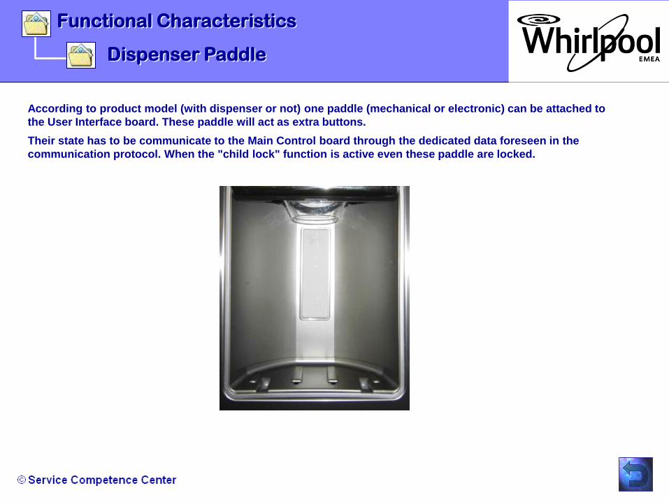
Functional Characteristics
Dispenser Paddle
According to product model (with dispenser or not) one paddle (mechanical or electronic) can be attached to
the User Interface board. These paddle will act as extra buttons.
Their state has to be communicate to the Main Control board through the dedicated data foreseen in the
communication protocol. When the "child lock" function is active even these paddle are locked.

Functional Characteristics
Evaporator Defrost Cycle
The defrost cycle starts when :
-The compressor effective running time for at least 8 hours (100%) was reached without any door opening.
OR
- The compressor effective running time at least 4 hours (50%) was reached and 20 counted door openings are reached.
OR
- A „emergency defrost“ cycle was requested by the board, due to low compressor running time in combination with
low ambient temperature.
OR
- The compressor running time is between 30% and 60%, the time between defrosts is 50 hours.
Standard Defrost Lenght:
At 230 volts with a semi clogged evaporator = 20 – 25 minutes
At 230 volts with a clean evaporator = 10 – 13 minutes
At 198 volts with a semi clogged evaporator = 27 – 32 minutes
At 198 volts with a clean evaporator = 17 – 20 minutes
Maximum defrost time = 40 minutes
Thermofuse temperature = 84°C
End of defrost temperature = 5°C
Dripping time after defrosting (heater OFF) = 2 minutes
Heater Wattage = 296 W

Functional Characteristics
Evaporator Defrost Cycle
Termination of the evaporator defrost cycle :
1. Standard functions switches OFF.
2. Freezer over temperature alarm is OFF
3. Compressor and both fans (Condenser & Evaporator) switches OFF.
4. The damper switches into CLOSE position.
5. The defrost heater starts to heat the evaporator with following timing:
Continuos working!
6. The evaporator sensor thermostat reaches the opening temperature (+5 C).
7. The heater switches OFF immediately.
8. The compressor switches ON after a elapsed time of 2 minutes.
9. The condenser fan switches ON with a time delay of 1 minute after the compressor start.
10.The damper and evaporator fan switches ON with a time delay of 1 minutes after the compressor start.
11.The defrost process before will be restored.
.

- Failure code: Power Outage
- Service Diagnostics in “Normal Mode”
- Activation of the “Service Diagnostics Routine”
- Service Mode Navigation Method
- User Interface Display Information
- Service Test Routine Document
Troubleshooting

Troubleshooting
Failure code: Power Outage
When there has been a power failure, the POWER OUTAGE icon will be turned ON to communicate this to the user as the power is
switched back on. At the same time, the blackout variable (Freezer max temperature reached) will be shown on the freezer display
(in this example -12°C) and Freezer temperature values will blink 3 times and Alert chime will play 3 times. Chime & blinking has to
be start at the same time.
The refrigerator digits will display the set temperature in the refrigerator compartment (the temperature which was set when the
power failure occurred).
The Power Outage Alarm Icon will remain on until the user resets it by pressing the RESET ALARM key.
When the user resets the power outage alarm, POWER OUTAGE icon will be turned OFF. A “disengage” chime is produced. If
previous state is Vacation Mode, it will retrieve after power outage alarm. Fast Freezing Mode is on, it will be terminated. Previous
user set point prior to Fast Freezing Mode will be retrieved.

Troubleshooting
Service Diagnostics In “Normal Mode”
Service Diagnostics Routines Side by Side products with “STEALTH” User Interface.
This routine is capable of controlling the product loads facilitating Service. In some cases is also
possible to inform the result of the current status of the load being tested.
Note: Service mode can be entered only in Normal mode (when cooling is ON)!
- The doors should be closed during Service mode.
- The Sleep mode is not allowed in Service mode.
- The Cooling OFF key combination is not allowed to toggle in Service mode.
- Exiting Service mode will produce DISENGAGE chime with Normal menu on the User Interface.

Troubleshooting
Activation of the “Service Diagnostics Routine”
Step 1:
To enable Service Diagnostic Routine press and hold SW1 & SW2 for 3 second.
•Press and hold for 3
seconds
•The 3 -> 2 -> 1 countdown will start on the User Interface ,with single key press beep.

Troubleshooting
Activation of the “Service Diagnostics Routine”
- During the 3, 2, 1 count down, if ice or water pad is pressed, it cancels the count down and no
dispensing is permitted.”3” blinks 3 times with “invalid” chime 3 times, and user has to release pad
and press Service mode key combination again to start it over.
- During the 3,2,1 count down , pressing any other key on UI or releasing Service mode key
combination (before 3secs) cancels the count down and “3” blinks 3 times along with “INVALID”
chime 3 times and user has to release all the pad which are pressing and start it over.
Note:
The blinking and chimes are synchronized so that the moment 3 blinks, the chime will be produced.

Troubleshooting
Entering the service key combination will activate the service mode as shown in above screen and produce engage chime.
Navigation:
- SW4 is used for step number decrement (downward).
- SW5 is used for step number increment (ascending).
Holding down either button (SW4/SW5) for two seconds will
cause the steps to decrement/increment steps numbers
accordingly at the rate of 2 steps per second.
•Step Number &
Step Info Display
Service Mode Navigation Method

Troubleshooting
•Step Number &
Step Info Display
- If the Last Step is reached, increasing the step will return to the First Step.
- If the First Step is reached, decreasing the step will return to the Last Step.
-SW3 key is used as the Change Setting Key. It is used to toggle the load which is tested therefore
change the step setting information.
- If any other key / pad is pressed in service mode (except for the specified steps), the pad / key
press will be ignored, no chimes will be produced while pad / key is pressed..
Service Mode Navigation Method

Troubleshooting
Service Mode Navigation Method
For products with only 2 Digits available, in order to accomplish the 3 digits requirements
in some steps, digits 1 and 2 will be displayed for two seconds, followed by digit 3 and a
dash for two seconds (dash will signify the end of the number). For products with 3 Digits
available the information shall be displayed using 3 digits.
Only two digits needed to display production software version and six digits will be
needed. This could be accomplished by cycling between digit pairs major revision,
minor revision, and test revision. Each digit pair shall be displayed for 2 seconds on the 2
digits display information and shall have 1 second blank time in between each each
sequence (test revision & major revision);
The 2 digits and 3 digits display information shall never appear at the same time. When
one is active the other shall be blanked;
For each step, only the load(s) being tested on the Step shall be turned ON (case
needed). Exiting each Step, the load(s) turned on in the Step shall be turned OFF

Troubleshooting
User Interface Display Information
Step Componen
t Action Display
1 FC
Thermistor
Read the current temperature of the FC thermistor from
Gemini Flash and compare this value. This information shall
be Dynamically update (every 1 second).
Value Read (VR):
COLD_LOWER_LIMIT Pass
HOT_UPPER_LIMIT Short
COLD_LOWER_LIMIT Open
01=Pass = GOOD
02=Open = DEFECT
03=Short = DEFECT
Press SW5 to display step number 1
•STEP
NO.:
•After entering to the Test Step, the component will be checked and the display shows the result (01, 02 or
o3).

Troubleshooting
User Interface Display Information
•After entering to the Test Step, the component will be checked and the display shows the result (01, 02 or
o3).
Press SW5 to display step number 2
•STEP
NO.:
2 RC
Thermistor
Read the current temperature of the RC
thermistor
from Gemini Flash and compare this value. This
information shall be Dynamically update (every 1
second).
Value Read (VR):
COLD_LOWER_LIMIT VR
HOT_UPPER_LIMIT Pass
VR > HOT_UPPER_LIMIT Short
VR< COLD_LOWER_LIMIT Open
01=Pass = GOOD
02=Open = DEFECT
03=Short = DEFECT

Troubleshooting
User Interface Display Information
After entering to the Test Step, the technician will see the current load status of the component (01, 02). The
SW3 key is used as the Change Setting Key. Means the technician can drive the load of the component to
OPEN / CLOSED or ON / OFF state. It is used to toggle the load which is tested therefore change the step
setting information.
Press SW5 to display step number 3
•STEP
NO.:
3 Evaporator fan
motor and air baffle
motor
- Turn on the Evaporator Fan and monitor the
Air Baffle feedback.
For products with variable speed evaporator fan,
the speed shall be set to 3000 rpm during this
step.
01 = Fan ON/Air baffle Open
02 = Fan ON/Air baffle Closed
(The display info is only
Available for air baffles motors
with feedback)….

Troubleshooting
User Interface Display Information
Press SW5 to display step number 4
•STEP
NO.:
After entering to the Test Step, the technician will see the current load status of the component (01, 02). The
SW3 key is used as the Change Setting Key. Means the technician can drive the load of the component to
OPEN / CLOSED or ON / OFF state. It is used to toggle the load which is tested therefore change the step
setting information.
4 Compressor and
condenser fan motor
(non-VCC models)
OR Condenser fan
motor (VCC models)
Control the Compressor and Condenser Fan Motor using the
Change Setting keys.
01 = ON
02 = OFF

Troubleshooting
Service Test Routine Document
Service Diagnostics for Side by Side from China „Dragon88 project“
General Description:
Service Diagnostics Routines Side by Side products with “STEALTH” User Interface.
This routine is capable of controlling the product loads facilitating Service. In some cases
is also possible to inform the result of the current status of the load being tested.
Note: Service mode can be entered only in Normal mode (when cooling is ON)!
- The doors should be closed during Service mode.
- The Sleep mode is not allowed in Service mode.
- The Cooling OFF key combination is not allowed to toggle in Service mode.
- Exiting Service mode will produce DISENGAGE chime with Normal menu on the User
Interface.
Activation of the “Service Diagnostics Routine”:
Step 1: To enable Service Diagnostic Routine press and hold SW1 & SW2 for 3 second.
The 3 -> 2 -> 1 countdown will start on the User Interface ,with single key press beep.
- During the 3, 2, 1 count down, if ice or water pad is pressed, it cancels the count down
and no dispensing is permitted.”3” blinks 3 times with “invalid” chime 3 times, and user
has to release pad and press Service mode key combination again to start it over.
- During the 3,2,1 count down , pressing any other key on UI or releasing Service mode key
combination (before 3secs) cancels the count down and “3” blinks 3 times along with
“INVALID” chime 3 times and user has to release all the pad which are pressing and start
it over.
Note: The blinking and chimes are synchronized so that the moment 3 blinks, the chime
will be produced.
Service Mode Navigation Method:
•To open the complete document, click on the left
document.

- Main Board
- User Interface
- Power Supply Board / 1x15W
- Stepper Motor Dispenser assy
- Dispenser paddle
- Dispenser LED
- Ice Motor IDI 3
- LED Lighting Side Walls
- LED Lighting Top Fridge Compartment
Technical Data
- Defrost Heater R600a
- Fan Motors
- Air Diffuser
- Ice Maker Sankyo IDI 3
- Filling Tube Heater
- Water valve Dual
- Solenoid Water Valve
- Overload Protector
- Run-Capacitor

Technical Data
Main Board
Power supply :
Nominal Voltage : 220 - 240 V AC
Operating Voltage Range : 185 - 264 V AC
Nominal Frequency : 50 Hz +/- 2%

Technical Data
User Interface
Supply voltage: 12Vdc (Isolated)
Current : 500 mA

Technical Data
Power Supply Board / 1x 15W
Input Voltage: 160 – 264V AC
Input Frequency: 48 – 62 Hz
Max Output Power: 15W
Output Voltage: 14V DC

Technical Data
Power Supply Board / 1x 15W
•Schematic single 15 Watt Power
Board

Technical Data
Stepper Motor Dispenser assy
Supply voltage : 14 V DC; +/-5%
DC resisistance: 50 Ohm; +/-7%
Current : 0.28 +/-0.2A / Phase (at 14V DC)
Number of Phases : 4 Phases
Exitation : 2 Phases
Step Angle : 5° (at rotor)
PULL-OUT Torque : 0.2 Nm MIN, 0.3 Nm MAX

Technical Data
Stepper Motor Dispenser assy

Technical Data
Dispenser paddle
Switch Rating: 14V DC, 50mA

Technical Data
Dispenser LED
Supply voltage ( nominal ) : 14 V DC +/- 5%

Technical Data
Ice Motor IDI 3
Supply voltage ( nominal ) : 220V AC / 50Hz
Rated Torque : 11,35N.m. @ 0,4 AMPS
RPM : 15 +/- 15%
Rated Amps: 0,4 A
Watt Range: 20 MAX.
•MOTOR DRIVING CIRCUIT

LED Lighting Side Walls
Technical Data
•LED POWER : 1W @350mA
•COLOR TEMPERATURE: 4425K +/-
325K
•LUMINOUS FLUX (MINIMUM): 82lm @350mA

LED Lighting Top Fridge Compartment
Built-In PowerSupply: Yes / 120V AC
Max. Current: 65 mA
Frequency: 50/60Hz
Number of LED„s: 3
Technical Data

Defrost Heater R600a
Supply voltage ( nominal ) : 240 V AC; 50/60 Hz
Power dissipation : 296W
Resistance : ~199 Ohm
Technical Data

Fan Motors
Condenser fan :
Supply voltage ( nominal ) : 240 V AC; 50/60 Hz
Full Load power dissipation : 3,4W / 1090RPM
No Load power dissipation: 3,0W / 1950RPM
Technical Data
Evaporator fan:
Supply voltage ( nominal ) : 12V DC
Max. power dissipation : 4,1 W
Speed : 1500 RPM

Air diffuser
Supply voltage ( nominal ) : 240 V AC; 50Hz
Max. power dissipation : 2.6 W
Resistance: 22377 Ohm
Technical Data

Technical Data
Ice-Maker Sankyo IDI 3
Supply voltage ( nominal ) : 12V DC
Motor power dissipation : 5 W (MAX 50mA)
Ice production per day : max. 0,8 kg (with
activated fast freezing
function under test / lab
condition)
Note: When the plus pole is connected with terminal 8 and the
minus pole is connected with terminal 7, the tray will rotate.
•Connector
View
•Sensor Value
Table

Technical Data
Filling Tube Heater
VOLT: 14 DC
WATT: 1,5
Ω MIN / MAX: 65,85 / 73,17
•MATERIAL: PVC105 C°

Water Valve Dual
Technical Data
•Water
Dispenser
•A: Yellow Quick Connect Fitting
•for 6,35mm Polyethylene tubing
•B: Green Quick Connect
Fitting
•for 7,94mm Polyethylene
tubing
Body Colour:
Yellow
•Ice
Maker
•COIL RATINGS: 220V / 50Hz / 20W
•FLOW RATE OUTLET A: 65cc /
7,5sec.
•FLOW RATE OUTLET B: 140cc
/ 7,5sec.
OPENING VOLTAGE: 190 V; 50Hz
WATER PRESSURE
RANGE: 1,38 - 8,27 bar

Solenoid Water Valve
COIL RATING : 220 - 240V AC; 50/60Hz; 20 WATTS
OPENING VOLTAGE: 190 V; 50/60Hz
WATER PRESSURE RANGE: 1,38 - 8,27 bar
OUTLET FLOW RATE: 180cc – 600cc / 7.5 sec.
QUICK CONNECT FITTING: 7,94mm
Technical Data

Technical Data
Overload Protector
•PART DESCRIPTION: 4TM 233NFBYY
•TRIP TIME (SECONDS): 5 – 15
•TEST CURRENT AMPS: 7.4
•70 C° TRIP AMPS: 1.7
•NO CURRENT TRIP TEMP. C°: 105
•RESET TEMP. C°: 61
•FOR COMPRESSOR TYPE:
EMD80CLT

Technical Data
Run - Capacitor
•RATED VOLTAGE: 220-240V
•RATED CAPACITANCE: 5uF
•FREQUENCY Hz: 50
•TERMINAL: 4.8 X 0.8mm

- Disassembling Door Handle
- Disassembling Evaporator Defrost Heater
- Disassembling Core Board & Power Board
- Disassembling User Interface with I&W
- Disassembling Ice Crusher Motor IDI 2
- Disassembling Sankyo IDI Ice-Maker
- Disassembling Ice Maker Water Tube
WILL BE PREPARED WHEN FINAL APPLIANCE VERSION IS
AVAILABLE!
Repair Guide Line / Disassembling

Documents
Information Letter for Sankyo Ice-Maker
NTC Resistance vs Temperature Table
Service Diagnostic Routine
Water Filter Cartridge Drawing
Example of Mexico SxS Service Manual
NTC TABLE
T (ºC) T (ºF) R ( ) T (ºC) T (ºF) R ( ) T (ºC) T (ºF) R ( ) T (ºC) T (ºF) R ( ) T (ºC) T (ºF) R ( )
-40,00 -40,00 88471,01 -17,22 1,00 22067,86 2,22 36,00 7828,32 22,00 71,60 3072,90 46,67 116,00 1102,97
-39,44 -39,00 85311,51 -17,00 1,40 21792,16 2,78 37,00 7613,56 22,22 72,00 3042,64 47,22 117,00 1079,54
-38,89 -38,00 82275,70 -16,67 2,00 21385,77 3,00 37,40 7529,52 22,78 73,00 2968,47 47,78 118,00 1056,68
-38,33 -37,00 79358,35 -16,11 3,00 20727,06 3,33 38,00 7405,39 23,00 73,40 2939,37 48,33 119,00 1034,37
-37,78 -36,00 76554,47 -16,00 3,20 20598,04 3,89 39,00 7203,58 23,33 74,00 2896,33 48,89 120,00 1012,59
-37,22 -35,00 73859,28 -15,56 4,00 20090,84 4,00 39,20 7163,97 23,89 75,00 2826,17 49,44 121,00 991,34
-36,67 -34,00 71268,22 -15,00 5,00 19476,28 4,44 40,00 7007,93 24,00 75,20 2812,37 50,00 122,00 970,60
-36,11 -33,00 68776,95 -14,44 6,00 18882,57 5,00 41,00 6818,23 24,44 76,00 2757,93 50,56 123,00 950,35
-35,56 -32,00 66381,30 -14,00 6,80 18422,10 5,56 42,00 6634,27 25,00 77,00 2691,55 51,11 124,00 930,59
-35,00 -31,00 64077,31 -13,89 7,00 18308,95 6,00 42,80 6491,12 25,56 78,00 2626,97 51,67 125,00 911,29
-34,44 -30,00 61861,18 -13,33 8,00 17754,66 6,11 43,00 6455,87 26,00 78,80 2576,57 52,22 126,00 892,45
-33,89 -29,00 59729,29 -13,00 8,60 17431,08 6,67 44,00 6282,85 26,11 79,00 2564,15 52,78 127,00 874,06
-33,33 -28,00 57678,16 -12,78 9,00 17219,00 7,00 44,60 6181,54 26,67 80,00 2503,02 53,33 128,00 856,10
-32,78 -27,00 55704,48 -12,22 10,00 16701,29 7,22 45,00 6115,02 27,00 80,60 2467,14 53,89 129,00 838,56
-32,22 -26,00 53805,08 -12,00 10,40 16499,09 7,78 46,00 5952,21 27,22 81,00 2443,54 54,44 130,00 821,43
-31,67 -25,00 51976,94 -11,67 11,00 16200,87 8,00 46,40 5888,46 27,78 82,00 2385,65 55,00 131,00 804,71
-31,11 -24,00 50217,16 -11,11 12,00 15717,11 8,33 47,00 5794,26 28,00 82,40 2362,94 55,56 132,00 788,37
-30,56 -23,00 48522,96 -11,00 12,20 15622,30 8,89 48,00 5641,01 28,33 83,00 2329,32 56,11 133,00 772,41
-30,00 -22,00 46891,70 -10,56 13,00 15249,40 9,00 48,20 5610,91 28,89 84,00 2274,49 56,67 134,00 756,82
-29,44 -21,00 45320,84 -10,00 14,00 14797,16 9,44 49,00 5492,31 29,00 84,20 2263,70 57,22 135,00 741,59
-29,00 -20,20 44106,01 -9,44 15,00 14359,83 10,00 50,00 5348,00 29,44 85,00 2221,12 57,78 136,00 726,71
-28,89 -20,00 43807,96 -9,00 15,80 14020,35 10,56 51,00 5207,95 30,00 86,00 2169,17 58,33 137,00 712,18
-28,33 -19,00 42350,73 -8,89 16,00 13936,88 11,00 51,80 5098,87 30,56 87,00 2118,59 58,89 138,00 697,97
-28,00 -18,40 41502,17 -8,33 17,00 13527,79 11,11 52,00 5072,01 31,11 88,00 2069,35 59,44 139,00 684,10
-27,78 -18,00 40946,93 -8,00 17,60 13288,78 11,67 53,00 4940,05 31,67 89,00 2021,41 60,00 140,00 670,53
-27,22 -17,00 39594,43 -7,78 18,00 13132,06 12,00 53,60 4862,74 32,22 90,00 1974,72 60,56 141,00 657,28
-27,00 -16,60 39067,34 -7,22 19,00 12749,21 12,22 54,00 4811,95 32,78 91,00 1929,25 61,11 142,00 644,33
-26,67 -16,00 38291,21 -7,00 19,40 12599,57 12,78 55,00 4687,58 33,33 92,00 1884,97 61,67 143,00 631,67
-26,11 -15,00 37035,31 -6,67 20,00 12378,79 13,00 55,40 4638,85 33,89 93,00 1841,85 62,22 144,00 619,29
-26,00 -14,80 36789,64 -6,11 21,00 12020,35 13,33 56,00 4566,83 34,44 94,00 1799,84 62,78 145,00 607,19
-25,56 -14,00 35824,86 -6,00 21,20 11950,06 13,89 57,00 4449,56 35,00 95,00 1758,91 63,33 146,00 595,37
-25,00 -13,00 34658,08 -5,56 22,00 11673,47 14,00 57,20 4426,52 35,56 96,00 1719,05 63,89 147,00 583,80
-24,44 -12,00 33533,25 -5,00 23,00 11337,75 14,44 58,00 4335,68 36,11 97,00 1680,20 64,44 148,00 572,50
-24,00 -11,20 32662,49 -4,44 24,00 11012,79 15,00 59,00 4225,08 36,67 98,00 1642,36 65,00 149,00 561,45
-23,89 -11,00 32448,74 -4,00 24,80 10760,31 15,56 60,00 4117,65 37,22 99,00 1605,48 65,56 150,00 550,64
-23,33 -10,00 31402,98 -3,89 25,00 10698,21 16,00 60,80 4033,92 37,78 100,00 1569,54 66,11 151,00 540,07
-23,00 -9,40 30793,49 -3,33 26,00 10393,64 16,11 61,00 4013,29 38,33 101,00 1534,51 66,67 152,00 529,74
-22,78 -9,00 30394,45 -3,00 26,60 10215,57 16,67 62,00 3911,91 38,89 102,00 1500,38 67,22 153,00 519,63
-22,22 -8,00 29421,72 -2,78 27,00 10098,75 17,00 62,60 3852,47 39,44 103,00 1467,10 67,78 154,00 509,74
-22,00 -7,60 29042,35 -2,22 28,00 9813,19 17,22 63,00 3813,41 40,00 104,00 1434,67 68,33 155,00 500,07
-21,67 -7,00 28483,41 -2,00 28,40 9701,51 17,78 64,00 3717,70 40,56 105,00 1403,04 68,89 156,00 490,61
-21,11 -6,00 27578,19 -1,67 29,00 9536,64 18,00 64,40 3680,18 41,11 106,00 1372,22 69,44 157,00 481,36
-21,00 -5,80 27401,01 -1,11 30,00 9268,79 18,33 65,00 3624,69 41,67 107,00 1342,16 70,00 158,00 472,31
-20,56 -5,00 26704,79 -1,00 30,20 9216,24 18,89 66,00 3534,31 42,22 108,00 1312,85 xxx xxx xxx
-20,00 -4,00 25862,00 -0,56 31,00 9009,34 19,00 66,20 3516,54 42,78 109,00 1284,27 xxx xxx xxx
-19,44 -3,00 25048,64 0,00 32,00 8758,00 19,44 67,00 3446,46 43,33 110,00 1256,39 xxx xxx xxx
-19,00 -2,20 24418,39 0,56 33,00 8514,49 20,00 68,00 3361,07 43,89 111,00 1229,21 xxx xxx xxx
-18,89 -2,00 24263,60 1,00 33,80 8325,14 20,56 69,00 3278,07 44,44 112,00 1202,69 xxx xxx xxx
-18,33 -1,00 23505,80 1,11 34,00 8278,54 21,00 69,80 3213,34 45,00 113,00 1176,83 xxx xxx xxx
-18,00 -0,40 23063,77 1,67 35,00 8049,91 21,11 70,00 3197,38 45,56 114,00 1151,60 xxx xxx xxx
-17,78 0,00 22774,22 2,00 35,60 7916,13 21,67 71,00 3118,93 46,11 115,00 1126,99 xxx xxx xxx
Service Diagnostics for Side by Side from China „Dragon88 project“
General Description:
Service Diagnostics Routines Side by Side products with “STEALTH” User Interface.
This routine is capable of controlling the product loads facilitating Service. In some cases
is also possible to inform the result of the current status of the load being tested.
Note: Service mode can be entered only in Normal mode (when cooling is ON)!
- The doors should be closed during Service mode.
- The Sleep mode is not allowed in Service mode.
- The Cooling OFF key combination is not allowed to toggle in Service mode.
- Exiting Service mode will produce DISENGAGE chime with Normal menu on the User
Interface.
Activation of the “Service Diagnostics Routine”:
Step 1: To enable Service Diagnostic Routine press and hold SW1 & SW2 for 3 second.
The 3 -> 2 -> 1 countdown will start on the User Interface ,with single key press beep.
- During the 3, 2, 1 count down, if ice or water pad is pressed, it cancels the count down
and no dispensing is permitted.”3” blinks 3 times with “invalid” chime 3 times, and user
has to release pad and press Service mode key combination again to start it over.
- During the 3,2,1 count down , pressing any other key on UI or releasing Service mode key
combination (before 3secs) cancels the count down and “3” blinks 3 times along with
“INVALID” chime 3 times and user has to release all the pad which are pressing and start
it over.
Note: The blinking and chimes are synchronized so that the moment 3 blinks, the chime
will be produced.
Service Mode Navigation Method: