Embed Size (px)
Citation preview
SIDACtor® Protection Thyristors
Revised: 01/09/14
© 2014 Littelfuse, Inc.Specifications are subject to change without notice.
Baseband Protection (Voice-DS1)
SIDACtor® Series, DO-214
Electrical Characteristics
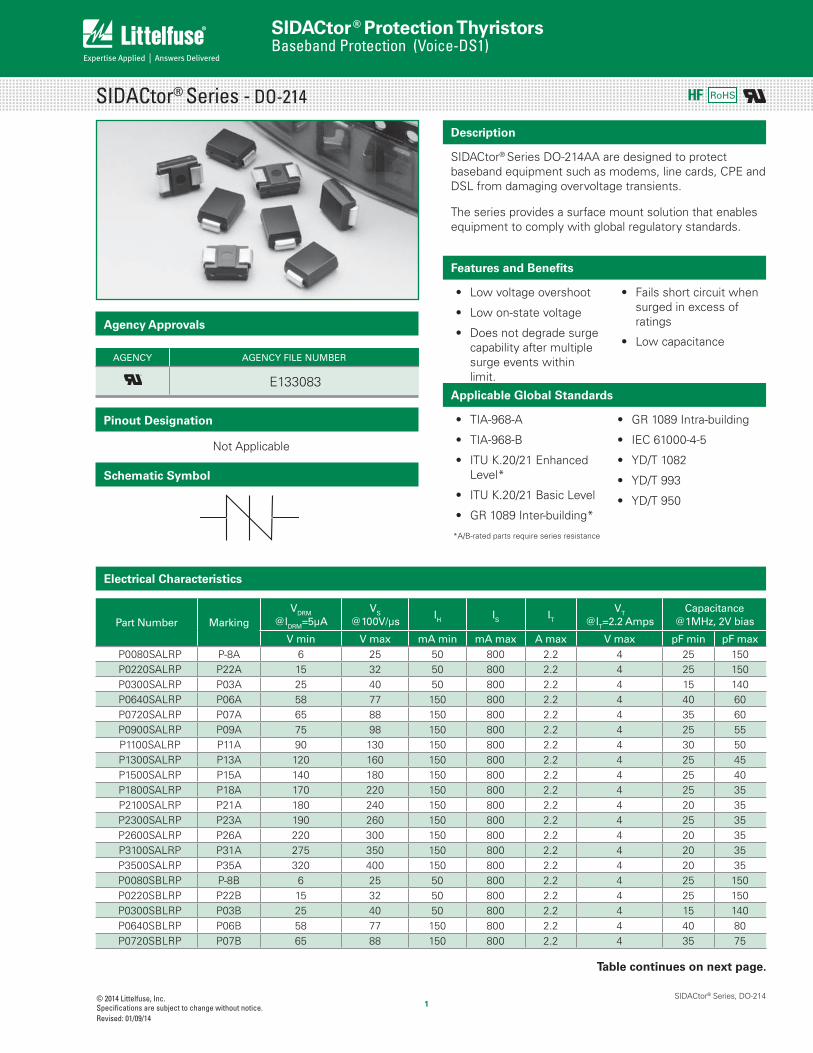
SIDACtor® Series - DO-214
SIDACtor® Series DO-214AA are designed to protect baseband equipment such as modems, line cards, CPE and DSL from damaging overvoltage transients.
The series provides a surface mount solution that enables equipment to comply with global regulatory standards.
Description
AGENCY AGENCY FILE NUMBER
E133083
Agency Approvals
Features and Benefits
Low voltage overshoot
Low on-state voltage
Does not degrade surge capability after multiple surge events within limit.
Fails short circuit when surged in excess of ratings
Low capacitance
Part Number MarkingVDRM
@lDRM=5μAVS
@100V/μsIH IS IT
VT
@IT=2.2 AmpsCapacitance
@1MHz, 2V bias
V min V max mA min mA max A max V max pF min pF maxP0080SALRP P-8A 6 25 50 800 2.2 4 25 150P0220SALRP P22A 15 32 50 800 2.2 4 25 150P0300SALRP P03A 25 40 50 800 2.2 4 15 140P0640SALRP P06A 58 77 150 800 2.2 4 40 60P0720SALRP P07A 65 88 150 800 2.2 4 35 60P0900SALRP P09A 75 98 150 800 2.2 4 25 55P1100SALRP P11A 90 130 150 800 2.2 4 30 50P1300SALRP P13A 120 160 150 800 2.2 4 25 45P1500SALRP P15A 140 180 150 800 2.2 4 25 40P1800SALRP P18A 170 220 150 800 2.2 4 25 35P2100SALRP P21A 180 240 150 800 2.2 4 20 35P2300SALRP P23A 190 260 150 800 2.2 4 25 35P2600SALRP P26A 220 300 150 800 2.2 4 20 35P3100SALRP P31A 275 350 150 800 2.2 4 20 35P3500SALRP P35A 320 400 150 800 2.2 4 20 35P0080SBLRP P-8B 6 25 50 800 2.2 4 25 150P0220SBLRP P22B 15 32 50 800 2.2 4 25 150P0300SBLRP P03B 25 40 50 800 2.2 4 15 140P0640SBLRP P06B 58 77 150 800 2.2 4 40 80P0720SBLRP P07B 65 88 150 800 2.2 4 35 75
Applicable Global Standards
TIA-968-A
TIA-968-B
ITU K.20/21 Enhanced Level*
ITU K.20/21 Basic Level
GR 1089 Inter-building*
GR 1089 Intra-building
IEC 61000-4-5
YD/T 1082
YD/T 993
YD/T 950
*A/B-rated parts require series resistance
Pinout Designation
Schematic Symbol
Not Applicable
Table continues on next page.
RoHS

SIDACtor® Protection Thyristors
Revised: 01/09/14
© 2014 Littelfuse, Inc.Specifications are subject to change without notice.
Baseband Protection (Voice-DS1)
SIDACtor® Series, DO-214
Electrical Parameters (continued)
Surge Ratings
Ser
ies
IPP ITSM50/60 Hz
di/dt0.2x310 1
0.5x700 22x10 1
2x10 28x20 1
1.2x50 210x160 1
10x160 210x560 1
10x560 25x320 1
9x720 210x360 1
10x360 210x1000 1
10x1000 25x310 1
10x700 2
A min A min A min A min A min A min A min A min A min A min Amps/μs max
A 20 150 150 90 50 75 75 45 75 20 500
B 25 250 250 150 100 100 125 80 100 25 500
C 50 500 400 200 150 200 175 100 200 3 30 500
Notes:
1 Current waveform in μs2 Voltage waveform in μs3 For surge rating of P4500SCLRP 10x700μs min=150A & typical=180A
- Peak pulse current rating (IPP) is repetitive and guaranteed for the life of the product.- IPP ratings applicable over temperature range of -40ºC to +85ºC- The device must initially be in thermal equilibrium with -40°C < TJ < +150°C
Part Number MarkingVDRM
@lDRM=5μAVS
@100V/μsIH IS IT
VT
@IT=2.2 AmpsCapacitance
@1MHz, 2V bias
V min V max mA min mA max A max V max pF min pF maxP0900SBLRP P09B 75 98 150 800 2.2 4 35 70P1100SBLRP P11B 90 130 150 800 2.2 4 30 70P1300SBLRP P13B 120 160 150 800 2.2 4 25 60P1500SBLRP P15B 140 180 150 800 2.2 4 25 55P1800SBLRP P18B 170 220 150 800 2.2 4 25 50P2100SBLRP P21B 180 240 150 800 2.2 4 20 35P2300SBLRP P23B 190 260 150 800 2.2 4 25 50P2600SBLRP P26B 220 300 150 800 2.2 4 20 45P3100SBLRP P31B 275 350 150 800 2.2 4 20 45P3500SBLRP P35B 320 400 150 800 2.2 4 20 40P4500SBLRP P45B 400 530 150 800 2.2 4 20 65P0080SCLRP P-8C 6 25 50 800 2.2 4 45 260P0220SCLRP P22C 15 32 50 800 2.2 4 30 240P0300SCLRP P03C 25 40 50 800 2.2 4 25 250P0640SCLRP P06C 58 77 150 800 2.2 4 55 155P0720SCLRP P07C 65 88 150 800 2.2 4 50 150P0900SCLRP P09C 75 98 150 800 2.2 4 45 140P1100SCLRP P11C 90 130 150 800 2.2 4 45 115P1300SCLRP P13C 120 160 150 800 2.2 4 40 105P1500SCLRP P15C 140 180 150 800 2.2 4 35 95P1800SCLRP P18C 170 220 150 800 2.2 4 35 90P2100SCLRP P21C 180 240 150 800 2.2 4 30 90P2300SCLRP P23C 190 260 150 800 2.2 4 30 80P2600SCLRP P26C 220 300 150 800 2.2 4 30 80P3100SCLRP P31C 275 350 150 800 2.2 4 30 70P3500SCLRP P35C 320 400 150 800 2.2 4 25 65P4500SCLRP P45C 400 530 150 800 2.2 4 20 65
Notes:- Absolute maximum ratings measured at TA= 25ºC (unless otherwise noted).- Devices are bi-directional.

SIDACtor® Protection Thyristors
Revised: 01/09/14
© 2014 Littelfuse, Inc.Specifications are subject to change without notice.
Baseband Protection (Voice-DS1)
SIDACtor® Series, DO-214
25°C
Case Temperature (TC) - ºC
2.0
1.8
1.6
1.4
1.2
1.0
0.8
0.6
0.4-40 -20 0 20 40 60 80 100 120 140 160
Ra
tio
of
I H
I H (T
C =
25
ºC)
Normalized VS Change vs. Junction Temperature Normalized DC Holding Current vs. Case Temperature
IH
IT
IS
IDRM
VDRMVT
+V-V
+I
-I
VS
50
100
0tr td
0
PeakValue
Half Value
t – Time (μs)
I PP –
Pea
k P
ulse
Cur
rent
– %
I PP tr = rise time to peak value
td = decay time to half value
Waveform = tr x td
V-I Characteristics tr x td Pulse Waveform
Package Symbol Parameter Value Unit
DO-214AA TJ Operating Junction Temperature Range -40 to +150 °C
TS Storage Temperature Range -65 to +150 °C
R0JA Thermal Resistance: Junction to Ambient 90 °C/W
Thermal Considerations
-8-40 -20 0 20 40 60 80 100 120 140 160
-6
-4
0
2
4
6
8
10
12
14
Junction Temperature (TJ) – °C
Perc
ent
of V
S C
han
ge
– %
25 °C

SIDACtor® Protection Thyristors
Revised: 01/09/14
© 2014 Littelfuse, Inc.Specifications are subject to change without notice.
Baseband Protection (Voice-DS1)
SIDACtor® Series, DO-214
Physical Specifications Environmental Specifications
Lead Material Copper Alloy
Terminal Finish 100% Matte-Tin Plated
Body MaterialUL recognized epoxy meeting flammability classification 94V-0
Time
Tem
pe
ratu
re
TP
TL
TS(max)
TS(min)
25
tP
tL
tS
time to peak temperature(t 25ºC to peak)
Ramp-down
Ramp-up
Preheat
Critical ZoneTL to TP
Figure 1
Soldering Parameters
Part Numbering
CONSTRUCTION VARIABLE
REEL PACK
IPP RATING
RoHS COMPLIANT
TYPEP = SIDACtor
P x L RP
MEDIAN VOLTAGE
PACKAGE TYPE
xxx 0 S
High Temp Voltage Blocking
80% Rated VDRM (VAC Peak ) +125°C or +150°C, 504 or 1008 hrs. MIL-STD-750 (Method 1040) JEDEC, JESD22-A-101
Temp Cycling-65°C to +150°C, 15 min. dwell, 10 up to 100 cycles. MIL-STD-750 (Method 1051) EIA/JEDEC, JESD22-A104
Biased Temp & Humidity
52 VDC (+85°C) 85%RH, 504 up to 1008 hrs. EIA/JEDEC, JESD22-A-101
High Temp Storage+150°C 1008 hrs. MIL-STD-750 (Method 1031) JEDEC, JESD22-A-101
Low Temp Storage -65°C, 1008 hrs.
Thermal Shock0°C to +100°C, 5 min. dwell, 10 sec. transfer, 10 cycles. MIL-STD-750 (Method 1056) JEDEC, JESD22-A-106
Autoclave (Pressure Cooker Test)
+121°C, 100%RH, 2atm, 24 up to 168 hrs. EIA/JEDEC, JESD22-A-102
Resistance to Solder Heat
+260°C, 30 secs. MIL-STD-750 (Method 2031)
Moisture Sensitivity Level
85%RH, +85°C, 168 hrs., 3 reflow cycles (+260°C Peak). JEDEC-J-STD-020, Level 1
Reflow ConditionPb-Free assembly (see Fig. 1)
Pre Heat
- Temperature Min (Ts(min)) +150°C- Temperature Max (Ts(max)) +200°C- Time (Min to Max) (ts) 60-180 secs.
Average ramp up rate (Liquidus Temp (TL) to peak) 3°C/sec. Max.
TS(max) to TL - Ramp-up Rate 3°C/sec. Max.
Reflow- Temperature (TL) (Liquidus) +217°C- Temperature (tL) 60-150 secs.
Peak Temp (TP) +260(+0/-5)°C
Time within 5°C of actual Peak Temp (tp) 30 secs. Max.
Ramp-down Rate 6°C/sec. Max.
Time 25°C to Peak Temp (TP) 8 min. Max.
Do not exceed +260°C
Part Marking
PxxxDate Code
Part Marking Code(Refer to Electrical Characteristics Table)
xxxxx

SIDACtor® Protection Thyristors
Revised: 01/09/14
© 2014 Littelfuse, Inc.Specifications are subject to change without notice.
Baseband Protection (Voice-DS1)
SIDACtor® Series, DO-214
Package Type Description Quantity Added Suffix Industry Standard
SDO-214AA
Tape & Reel Pack2500 RP EIA-481-D
Packing Options
Tape and Reel Specification — DO-214AA
0.472(12.0) 0.36
(9.2)
0.315(8.0)
0.157(4.0)
0.49(12.4)
0.512 (13.0) Arbor Hole Dia.
12.99(330.0) Dimensions are in inches
(and millimeters).
Direction of Feed
0.059 DIA(1.5)Cover tape
Dimensions — DO-214AA
0.079(2.0)
0.110(2.8)
0.079(2.0)
Pad Outline
H
KE
F
G
AC
BD
CaseTemperature
MeasurementPoint
inch(millimeter)
DimensionsInches Millimeters
Min Max Min Max
A 0.130 0.156 3.30 3.95
B 0.201 0.220 5.10 5.60
C 0.077 0.087 1.95 2.20
D 0.159 0.181 4.05 4.60
E 0.030 0.063 0.75 1.60
F 0.075 0.096 1.90 2.45
G 0.002 0.008 0.05 0.20
H 0.077 0.104 1.95 2.65
K 0.006 0.016 0.15 0.41


![[Secs 16.1 Dunlap] Conservation Laws - II [Secs 2.2, 2.3, 16.4, 16.5 Dunlap]](https://img.dokumen.tips/doc/110x75/5697c0101a28abf838ccacf3/secs-161-dunlap-conservation-laws-ii-secs-22-23-164-165-dunlap.jpg)


![[Secs 16.1 Dunlap]](https://img.dokumen.tips/doc/110x75/56812bd4550346895d9036ea/secs-161-dunlap.jpg)

