Embed Size (px)
Citation preview

No.EX※※-OMW0016
PRODUCT NAME
SI unit
( device)
MODEL / Series / Product Number
EX260-SIL1
-1-
No.EX※※-OMW0016
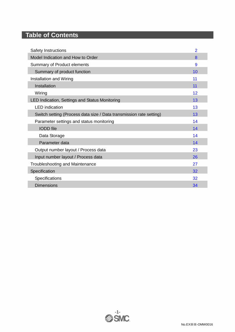
Table of Contents
Safety Instructions 2
Model Indication and How to Order 8
Summary of Product elements 9
Summary of product function 10
Installation and Wiring 11
Installation 11
Wiring 12
LED Indication, Settings and Status Monitoring 13
LED indication 13
Switch setting (Process data size / Data transmission rate setting) 13
Parameter settings and status monitoring 14
IODD file 14
Data Storage 14
Parameter data 14
Output number layout / Process data 23
Input number layout / Process data 26
Troubleshooting and Maintenance 27
Specification 32
Specifications 32
Dimensions 34

-2-
No.EX※※-OMW0016
Safety Instructions
These safety instructions are intended to prevent hazardous situations and/or equipment damage. These instructions indicate the level of potential hazard with the labels of "Caution", "Warning" or "Danger". They are all important notes for safety and must be followed in addition to International Standards (ISO/IEC)*1), and other safety regulations. *1) ISO 4414: Pneumatic fluid power -- General rules relating to systems.
ISO 4413: Hydraulic fluid power -- General rules relating to systems. IEC 60204-1: Safety of machinery -- Electrical equipment of machines .(Part 1: General requirements) ISO 10218: Manipulating industrial robots -Safety. etc.
Caution Caution indicates a hazard with a low level of risk which, if not avoided, could
result in minor or moderate injury.
Warning Warning indicates a hazard with a medium level of risk which, if not avoided,
could result in death or serious injury.
Danger Danger indicates a hazard with a high level of risk which, if not avoided, will
result in death or serious injury.
Warning 1. The compatibility of the product is the responsibility of the person who designs the
equipment or decides its specifications. Since the product specified here is used under various operating conditions, its compatibility with specific equipment must be decided by the person who designs the equipment or decides its specifications based on necessary analysis and test results. The expected performance and safety assurance of the equipment will be the responsibility of the person who has determined its compatibility with the product. This person should also continuously review all specifications of the product referring to its latest catalog information, with a view to giving due consideration to any possibility of equipment failure when configuring the equipment.
2. Only personnel with appropriate training should operate machinery and equipment. The product specified here may become unsafe if handled incorrectly. The assembly, operation and maintenance of machines or equipment including our products must be performed by an operator who is appropriately trained and experienced.
3. Do not service or attempt to remove product and machinery/equipment until safety is confirmed. 1. The inspection and maintenance of machinery/equipment should only be performed after measures to
prevent falling or runaway of the driven objects have been confirmed. 2. When the product is to be removed, confirm that the safety measures as mentioned above are
implemented and the power from any appropriate source is cut, and read and understand the specific product precautions of all relevant products carefully.
3. Before machinery/equipment is restarted, take measures to prevent unexpected operation and malfunction. 4. Contact SMC beforehand and take special consideration of safety measures if the
product is to be used in any of the following conditions. 1. Conditions and environments outside of the given specifications, or use outdoors or in a place
exposed to direct sunlight. 2. Installation on equipment in conjunction with atomic energy, railways, air navigation, space, shipping,
vehicles, military, medical treatment, combustion and recreation, or equipment in contact with food and beverages, emergency stop circuits, clutch and brake circuits in press applications, safety equipment or other applications unsuitable for the standard specifications described in the product catalog.
3. An application which could have negative effects on people, property, or animals requiring special safety analysis.
4. Use in an interlock circuit, which requires the provision of double interlock for possible failure by using a mechanical protective function, and periodical checks to confirm proper operation.

-3-
No.EX※※-OMW0016
Safety Instructions
Caution 1.The product is provided for use in manufacturing industries.
The product herein described is basically provided for peaceful use in manufacturing industries. If considering using the product in other industries, consult SMC beforehand and exchange specifications or a contract if necessary. If anything is unclear, contact your nearest sales branch.
Limited warranty and Disclaimer/Compliance Requirements The product used is subject to the following "Limited warranty and Disclaimer" and "Compliance Requirements". Read and accept them before using the product.
Limited warranty and Disclaimer
1. The warranty period of the product is 1 year in service or 1.5 years after the product is
delivered, whichever is first.2) Also, the product may have specified durability, running distance or replacement parts. Please consult your nearest sales branch.
2. For any failure or damage reported within the warranty period which is clearly our responsibility, a replacement product or necessary parts will be provided. This limited warranty applies only to our product independently, and not to any other damage incurred due to the failure of the product.
3. Prior to using SMC products, please read and understand the warranty terms and disclaimers noted in the specified catalog for the particular products. 2) Vacuum pads are excluded from this 1 year warranty.
A vacuum pad is a consumable part, so it is warranted for a year after it is delivered. Also, even within the warranty period, the wear of a product due to the use of the vacuum pad or failure due to the deterioration of rubber material are not covered by the limited warranty.
Compliance Requirements 1. The use of SMC products with production equipment for the manufacture of weapons of
mass destruction (WMD) or any other weapon is strictly prohibited. 2. The exports of SMC products or technology from one country to another are governed by
the relevant security laws and regulation of the countries involved in the transaction. Prior to the shipment of a SMC product to another country, assure that all local rules governing that export are known and followed.

-4-
No.EX※※-OMW0016
Operator
This operation manual is intended for those who have knowledge of machinery using pneumatic equipment, and have sufficient knowledge of assembly, operation and maintenance of such equipment. Only those persons are allowed to perform assembly, operation and maintenance.
Read and understand this operation manual carefully before assembling, operating or providing maintenance to the product.
■Safety Instructions
Warning ■Do not disassemble, modify (including changing the printed circuit board) or repair.
An injury or failure can result.
■Do not operate the product outside of the specifications.
Do not use for flammable or harmful fluids.
Fire, malfunction, or damage to the product can result.
Verify the specifications before use.
■Do not operate in an atmosphere containing flammable or explosive gases.
Fire or an explosion can result.
This product is not designed to be explosion proof.
■If using the product in an interlocking circuit:
•Provide a double interlocking system, for example a mechanical system.
•Check the product regularly for proper operation.
Otherwise malfunction can result, causing an accident.
■The following instructions must be followed during maintenance:
•Turn off the power supply.
•Stop the air supply, exhaust the residual pressure and verify that the air is released before performing
maintenance.
Otherwise an injury can result.
Caution ■After maintenance is complete, perform appropriate functional inspections.
Stop operation if the equipment does not function properly.
Safety cannot be assured in the case of unexpected malfunction.
■Provide grounding to assure the noise resistance of the Serial System.
Individual grounding should be provided close to the product with a short cable.
-5-
No.EX※※-OMW0016
■NOTE
Follow the instructions given below when designing, selecting and handling the product.
The instructions on design and selection (installation, wiring, environment, adjustment, operation,
maintenance, etc.) described below must also be followed. Product specifications
•When conformity to UL is required, the SI unit should be used with a UL1310 Class 2 power supply.
•The SI unit is a UL approved product only if they have a mark on the body.
•Use the specified voltage.
Otherwise failure or malfunction can result.
•Reserve a space for maintenance.
Allow sufficient space for maintenance when designing the system.
•Do not remove any nameplates or labels.
This can lead to incorrect maintenance, or misreading of the operation manual, which could cause damage or
malfunction to the product.
It may also result in non-conformity to safety standards.

-6-
No.EX※※-OMW0016
Product handling Installation
•Do not drop, hit or apply excessive shock to the fieldbus system.
Otherwise damage to the product can result, causing malfunction.
•Tighten to the specified tightening torque.
If the tightening torque is exceeded the mounting screws may be broken.
IP67 protection cannot be guaranteed if the screws are not tightened to the specified torque.
•Never mount a product in a location that will be used as a foothold.
The product may be damaged if excessive force is applied by stepping or climbing onto it.
Wiring
•Avoid repeatedly bending or stretching the cables, or placing heavy load on them.
Repetitive bending stress or tensile stress can cause breakage of the cable.
•Wire correctly.
Incorrect wiring can break the product.
•Do not perform wiring while the power is on.
Otherwise damage to the fieldbus system and/or I/O device can result, causing malfunction.
•Do not route wires and cables together with power or high voltage cables.
Otherwise the fieldbus system and/or I/O device can malfunction due to interference of noise and surge voltage
from power and high voltage cables to the signal line.
Route the wires (piping) of the fieldbus system and/or I/O device separately from power or high voltage cables.
•Confirm proper insulation of wiring.
Poor insulation (interference from another circuit, poor insulation between terminals, etc.) can lead to excess
voltage or current being applied to the product, causing damage.
•Take appropriate measures against noise, such as using a noise filter, when the fieldbus system is
incorporated into equipment.
Otherwise noise can cause malfunction.
•Separate the power line for output devices from the power line for control.
Otherwise noise or induced surge voltage can cause malfunction.
Environment
•Select the proper type of protection according to the environment of operation.
IP67 protection is achieved when the following conditions are met.
(1) The units are connected properly with fieldbus cable with M12 connector and power cable with M12 (M8)
connector.
(2) Suitable mounting of each unit and manifold valve.
If using in an environment that is exposed to water splashes, please take measures such as using a cover.
•Do not use in a place where the product could be splashed by oil or chemicals.
If the product is to be used in an environment containing oils or chemicals such as coolant or cleaning solvent, even
for a short time, it may be adversely affected (damage, malfunction etc.).
•Do not use the product in an environment where corrosive gases or fluids could be splashed.
Otherwise damage to the product and malfunction can result.
•Do not use in an area where surges are generated.
If there is equipment which generates a large amount of surge (solenoid type lifter, high frequency induction furnace,
motor, etc.) close to the fieldbus system, this may cause deterioration or breakage of the internal circuit of the
fieldbus system. Avoid sources of surge generation and crossed lines.
•When a surge-generating load such as a relay or solenoid is driven directly, use an fieldbus system with
a built-in surge absorbing element.
Direct drive of a load generating surge voltage can damage the fieldbus system.
•The product is CE marked, but not immune to lightning strikes. Take measures against lightning strikes
in the system.
•Prevent foreign matter such as remnant of wires from entering the fieldbus system to avoid failure and
malfunction.

-7-
No.EX※※-OMW0016
•Mount the product in a place that is not exposed to vibration or impact.
Otherwise failure or malfunction can result.
•Do not use the product in an environment that is exposed to temperature cycle.
Heat cycles other than ordinary changes in temperature can adversely affect the inside of the product.
•Do not expose the product to direct sunlight.
If using in a location directly exposed to sunlight, shade the product from the sunlight.
Otherwise failure or malfunction can result.
•Keep within the specified ambient temperature range.
Otherwise malfunction can result.
•Do not operate close to a heat source, or in a location exposed to radiant heat.
Otherwise malfunction can result.
Adjustment and Operation
•Perform settings suitable for the operating conditions.
Incorrect setting can cause operation failure.
•Please refer to the PLC manufacturer's manual etc. for details of programming and addresses.
For the PLC protocol and programming refer to the relevant manufacturer's documentation.
•The surface on the product may be hot.
Maintenance
•Turn off the power supply, stop the supplied air, exhaust the residual pressure and verify the release of
air before performing maintenance.
There is a risk of unexpected malfunction.
•Perform regular maintenance and inspections.
There is a risk of unexpected malfunction.
•After maintenance is complete, perform appropriate functional inspections.
Stop operation if the equipment does not function properly.
Otherwise safety is not assured due to an unexpected malfunction or incorrect operation.
•Do not use solvents such as benzene, thinner etc. to clean the each unit.
They could damage the surface of the body and erase the markings on the body.
Use a soft cloth to remove stains.
For heavy stains, use a cloth soaked with diluted neutral detergent and fully squeezed, then wipe up the stains
again with a dry cloth.

-8-
No.EX※※-OMW0016
Model Indication and How to Order
EX260-SIL 1
Connector type, output specification
1 M12 connector, 32 outputs, PNP (negative common) / source
Fieldbus
IL IO-Link
: IO-Link is the first standardized IO technology worldwide (IEC 61131-9) for the
communication with sensors and also actuators and it is being disseminated under a
dedicated word mark/logo,

-9-
No.EX※※-OMW0016
Summary of Product elements
No. Element Description
1 IO-Link communication/
power supply connector
IO-Link communication interface for connection (Port Class B) including
power supply for solenoid valves (M12 5-pin plug, A-coded)
2 Ground terminal Functional earth (M3 screw)
3 Output connector Output signal interface for solenoid valve manifold
4 LED and switch LED display to indicate the status of the SI unit
Switch for setting of data transmission rate (COM2 or COM3)
5 Mounting hole Mounting hole for connection to the solenoid valve manifold
: Refer to page 13 for the LED Indication, Settings and Status Monitoring.
Accessories
Hexagon socket head cap screw 2 pcs. M3 x 30 screw for connection to the solenoid valve manifold

-10-
No.EX※※-OMW0016
■Summary of product function
I/O function
This device can control 32 outputs for solenoid valve control and check device status using cyclic data
communication via IO-Link system.
Fault action
Output action at a communication fault can be set by parameter, either Clear Output, Force Output or Hold
Last State.
Output switching counter
This device can count the number of output switching cycles on each single output and the count value can
be automatically stored in the device every hour or automatically in the SI unit when the IO-Link power is
turned off.
: Depending on the situation of the voltage change at power OFF, it may not be possible to save.
Device condition (diagnosis) monitoring
This device can provide information about the device condition (diagnosis) over the IO-Link.
•This device can detect various error status, such as internal hardware fault and output open/short circuit.
•This device can detect various warning status, such as solenoid power over-run/under-run and device
temperature over-run.
•Also, the device can notify when the output switching count reaches the upper limit value set by the user
arbitrarily.
Data Storage function
Data Storage is a function which enables a consistent and up-to-date set of device parameters to be stored
in the Master. The main purpose of the IO-Link Data Storage mechanism is to ease the replacement of
defect devices without using configuration, parameterization, or other tools.
When the user has assigned parameter values with the help of engineering tools, they are downloaded into
the device and become active parameters. Upon a system command, these parameters are uploaded
(copied) into the Data Storage within the Master.
The stored (saved) set of back-up parameters overwrite the active parameters (e.g. factory settings) within
the compatible replacement device.
Data Storage provides three different "Backup Levels" of parameters to be defined on the Master port using
engineering tools, Commissioning ("Disable"), Production ("Backup/Restore") and Production ("Restore").
"Backup" means that upload is enabled and "Restore" means that download is enabled.

-11-
No.EX※※-OMW0016
Installation and Wiring
■Installation
Connect solenoid valve manifold to the SI unit.
Dimensions for installation
n: number of solenoid valve stations
L 1 2 3 4 5 6 7 8
L1
120.7 136.7 152.7 168.7 184.7 200.7 216.7
L2 80 96 112 128 144 160 176
L 9 10 11 12 13 14 15 16
L1 232.7 248.7 264.7 280.7 296.7 312.7 328.7 344.7
L2 192 208 224 240 256 272 288 304
(mm)
The above table shows dimensions as an example for the SY5000 series solenoid valve manifold.
n
n
-12-
No.EX※※-OMW0016
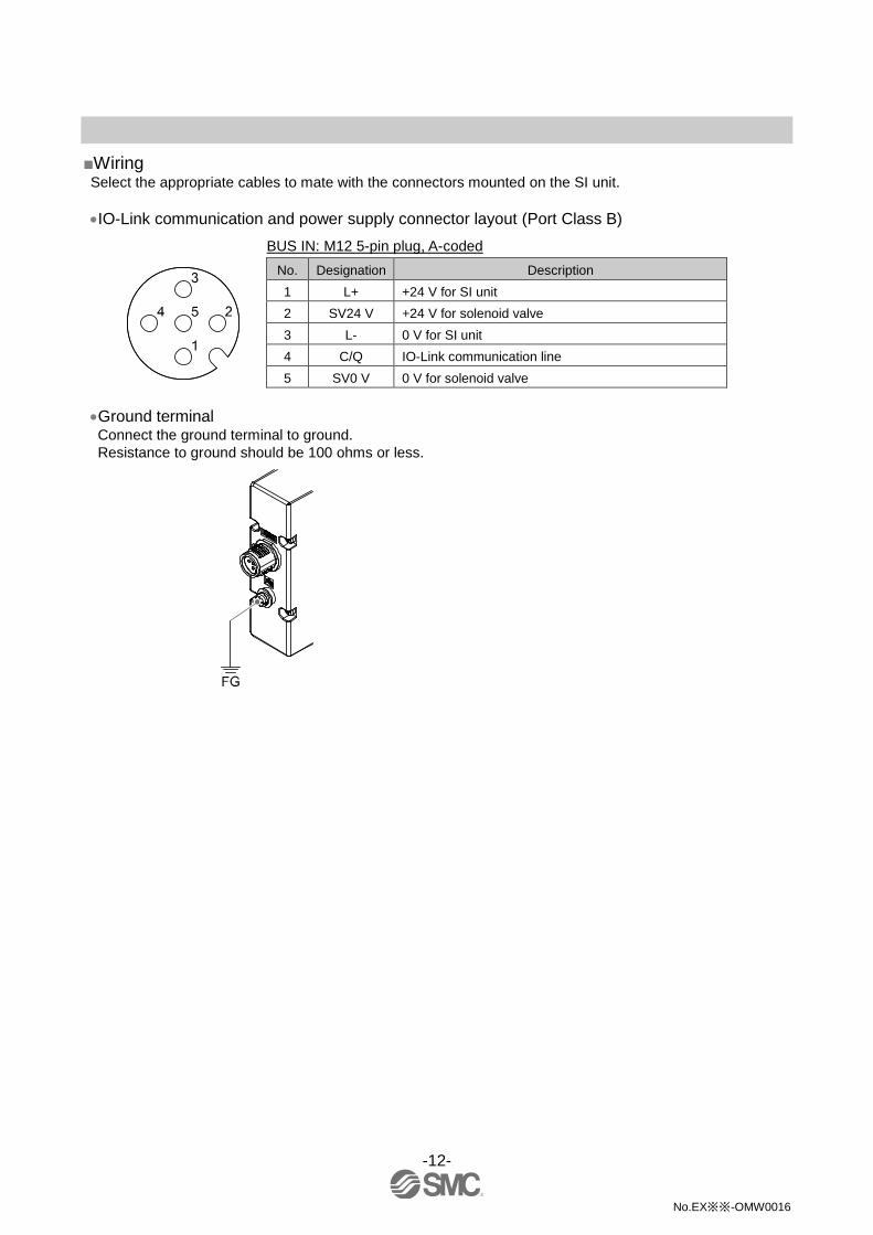
■Wiring
Select the appropriate cables to mate with the connectors mounted on the SI unit.
IO-Link communication and power supply connector layout (Port Class B)
BUS IN: M12 5-pin plug, A-coded
No. Designation Description
1 L+ +24 V for SI unit
2 SV24 V +24 V for solenoid valve
3 L- 0 V for SI unit
4 C/Q IO-Link communication line
5 SV0 V 0 V for solenoid valve
Ground terminal Connect the ground terminal to ground.
Resistance to ground should be 100 ohms or less.

-13-
No.EX※※-OMW0016
LED Indication, Settings and Status Monitoring
■LED indication
LED LED Status Description
COM
Green ON Power ON, IO-Link communication inactive
Green OFF Power OFF
Flashing Green IO-Link communication active
PWR(V)
Green ON Power for the solenoid valve is supplied
OFF Power for the solenoid valve is not supplied or outside the tolerance range
(19 V or less)
■Switch setting (Process data size / Data transmission rate setting) The switch should only be set with the power supply turned off.
Open the cover and set the DIP switch with a small flat blade screwdriver.
: The appropriate IODD file depends on each setting such as data transmission rate and process data size.
Refer to the following IODD file list for details (page 14).
-14-
No.EX※※-OMW0016
■Parameter settings and status monitoring
IODD file An IODD (I/O Device Description) is a file that provides all the necessary properties to establish
communication and the necessary parameters and their boundaries to establish the desired function of a
sensor or actuator.
It is the set of files of the main IODD file and image files such as a vendor logo, device picture and device
icon.
The corresponding IODD files of each product are as follows.
Product
Number
Data
Transmission rate Process data size IODD File
1
EX260-SIL1
COM3
(230.4 kbps) 0 byte input/4 bytes output
SMC-EX260-SIL1_04_3-yyyymmdd-IODD1.1
2 COM2
(38.4 kbps) SMC-EX260-SIL1_04_2-yyyymmdd-IODD1.1
3 COM3
(230.4 kbps) 2 bytes input/4 bytes output
(2 bytes input: Device Status)
SMC-EX260-SIL1_24_3-yyyymmdd-IODD1.1
4 COM2
(38.4 kbps) SMC-EX260-SIL1_24_2-yyyymmdd-IODD1.1
: "yyyymmdd" in the file name indicates data of file creation, where yyyy is the year, mm is the month and dd is the day.
Data Storage Data Storage is function which enables a consistent and up-to-date set of device parameters to be stored in
the Master.
When a single parameter (Index and Subindex) is changed and the changed parameters need to be
uploaded (copied) to the Master, a SystemCommand "ParamDownloadStore" needs to be sent to the SI
unit by the user to back up the parameters.
When entire parameters are set in the SI unit using "block parameter" from the IO-Link Tool, a
SystemCommand "ParamDownloadStore" will be sent automatically as a part of the block parameter
transmission sequence (the user does not need to execute that SystemCommand).
The stored (saved) set of back-up parameters can overwrite the active parameters (e.g. factory settings)
within a compatible replacement SI unit.
Service data The following table defines the parameters with read or write access, the so-called Direct Parameter Page
with a simplified access method and the ISDU parameter for complex parameters and commands.
Direct Parameter Page 1
DPP1 Access Parameter Name Value
Address
0x07 R Vendor ID 131
0x08
0x09
R Device ID
344: EX260-SIL1 (for in/out 0/4 bytes COM3)
345: EX260-SIL1 (for in/out 0/4 bytes COM2)
346: EX260-SIL1 (for in/out 2/4 bytes COM3)
347: EX260-SIL1 (for in/out 2/4 bytes COM2)
0x0A
0x0B
-15-
No.EX※※-OMW0016
ISDU Parameters
ISDU Access
1 Parameter Name
Data
Storage 2
Value Index
(dec) Sub-Index
0x0002
(2) 0 W SystemCommand N
Refer to page 16 "Coding
of System Command" for
details
0x000C
(12) 0 R/W Device Access Locks N
Refer to page 17 "Device
Access Locks" for details
0x0010
(16) 0 R Vendor Name N SMC Corporation
0x0011
(17) 0 R Vendor Text N www.smcworld.com
0x0012
(18) 0 R Product Name N
EX260-SIL1_in/out_
0/4 byte_COM3
(It depends on switch
setting 3)
0x0013
(19) 0 R Product ID N EX260-SIL1
0x0014
(20) 0 R Product Text N SI unit
0x0015
(21) 0 R Serial Number N "xxxxxxxx" 4
0x0016
(22) 0 R Hardware Revision N HW-Vx.y 5
0x0017
(23) 0 R Software Revision N FW-Vx.y 5
0x0018
(24) 0 R/W Application Specific Tag Y
"*******************
*************" 6
0x0024
(36) 0 R Device Status N
Refer to page 17 "Device
Status parameter" for
details
0x0025
(37) 1..8 R Detailed Device Status N
Refer to page 17
"Detailed Device Status
parameter" for details
1: Where “R” is Read and “W” is Write.
2: Where “Y” means “included in DataStorage” and “N” means “Not included in Data Storage”
3: EX260-SIL1_in/out_0/4 byte_COM3
EX260-SIL1_in/out_0/4 byte_COM2
EX260-SIL1_in/out_2/4 byte_COM3
EX260-SIL1_in/out_2/4 byte_COM2
: The data type is a character string with a fixed length of 8 octets.
5: Where "x" is the major revision number, "y" is the minor revision number.
6: The data type is a character string with a length from 16 to 32 octets.
-16-
No.EX※※-OMW0016
Coding of SystemCommand (index 2)
For ParamDownloadStore, Device reset, Application reset, Restore factory settings or Output switching
count value reset, the ISDU Index 0x002 (SystemCommand) should be used.
The buttons, a command interface to the SI unit, labelled with the following command name (except
ParamDownloadStore) are displayed in the IO-Link Tool. Each command is sent to the SI unit when the
button is clicked.
The coding of SystemCommand is specified in the following table.
Command
(dec) Command name Definition
0x05
(5) ParamDownloadStore
Backup instruction of parameter data
SI unit initiates a new Data Storage upload to
the Master
0x80
(128) Device reset
SI unit to perform a "warm start".
SI unit is reset to an initial state such as
power-on
0x81
(129) Application reset All outputs switching count value are cleared
0x82
(130) Restore factory settings
All parameter values are restored to factory
default setting and all output count values
are cleared
0xA0
(160) OUT0 count value reset Output 0 count value is cleared
0xA1
(161) OUT1 count value reset Output 1 count value is cleared
0xA2
(162) OUT2 count value reset Output 2 count value is cleared
…
…
…
0xAA
(170) OUT10 count value reset Output 10 count value is cleared
…
…
…
0xAF
(175) OUT15 count value reset Output 15 count value is cleared
…
…
…
0xBE
(190) OUT30 count value reset Output 30 count value is cleared
0xBF
(191) OUT31 count value reset Output 31 count value is cleared
-17-
No.EX※※-OMW0016
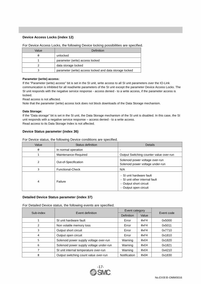
Device Access Locks (index 12)
For Device Access Locks, the following Device locking possibilities are specified.
Value Definition
0 unlocked
1 parameter (write) access locked
2 data storage locked
3 parameter (write) access locked and data storage locked
Parameter (write) access:
If the "Parameter (write) access" bit is set in the SI unit, write access to all SI unit parameters over the IO-Link
communication is inhibited for all read/write parameters of the SI unit except the parameter Device Access Locks. The
SI unit responds with the negative service response - access denied - to a write access, if the parameter access is
locked.
Read access is not affected.
Note that the parameter (write) access lock does not block downloads of the Data Storage mechanism.
Data Storage:
If the "Data storage" bit is set in the SI unit, the Data Storage mechanism of the SI unit is disabled. In this case, the SI
unit responds with a negative service response – access denied - to a write access.
Read access to its Data Storage Index is not affected.
Device Status parameter (index 36)
For Device status, the following Device conditions are specified.
Value Status definition Details
0 In normal operation -
1 Maintenance-Required Output Switching counter value over-run
2 Out-of-Specification Solenoid power voltage over-run
Solenoid power voltage under-run
3 Functional-Check N/A
4 Failure
- SI unit hardware fault
- SI unit other internal fault
- Output short circuit
- Output open circuit
Detailed Device Status parameter (index 37)
For Detailed Device status, the following events are specified.
Sub-index Event definition Event category
Event code Definition Value
1 SI unit hardware fault Error 0xF4 0x5000
2 Non volatile memory loss Error 0xF4 0x5011
3 Output short circuit Error 0xF4 0x7710
4 Output open circuit Error 0xF4 0x1810
5 Solenoid power supply voltage over-run Warning 0xE4 0x1820
6 Solenoid power supply voltage under-run Warning 0xE4 0x1821
7 SI unit internal temperature over-run Warning 0xE4 0x4210
8 Output switching count value over-run Notification 0xD4 0x1830

-18-
No.EX※※-OMW0016
Application Specific Parameters
Index
(dec)
Sub-
index
Access 1
Parameter name Data
type Default
Data
Storage 2
Description
0x54
(84) 1,2,3,4 R/W
Output Fault
Action U8 {0,0,0,0} Y
Determine how the SI unit
output act when a IO-Link
communication fault
(individual setting from
OUT0 to OUT31)
0: Output Fault Value
parameter setting value
1: hold last state
0x55
(85) 1,2,3,4 R/W Output Fault Value U8 {0,0,0,0} Y
If the Output Fault Action
parameter is set to 0, the
output of the SI unit
responds with a
user-defined fault value
when a communication
fault. (individual setting
from OUT0 to OUT31)
0: Clear Output (Set 0)
1: Force Output (Set 1)
0x44
(68) 1..32 R
Output Switching
Counts U32 {0,0…} N
Count the number of
switching times of each
output. The count value is
saved3 every hour, or
automatically4 in the SI unit
when the IO-Link power is
turned off.
When the counter reaches
the maximum value
4,294,967,295, this value is
retained and it does not
return to zero.
0x56
(86) 1,2,3,4 R/W
Output Open
Circuit Detection U8 {0,0,0,0} Y
Enable / disable Output
Open Circuit Detection
(individual setting from
OUT0 to OUT31)
0: disable
1: enable
0x57
(87) 1,2,3,4 R
Output Open
Circuit Status U8 {0,0,0,0} N
Output status for open
circuit
(individual status from
OUT0 to OUT31)
0: normal
1: open circuit

-19-
No.EX※※-OMW0016
Application Specific Parameters (continue)
Index
(dec)
Sub-
index
Access 1
Parameter name Data
type Default
Data
Storage 2
Description
0x58
(88) 1,2,3,4 R
Output Short
Circuit Status U8 {0,0,0,0} N
Output status for short
circuit
(individual status from
OUT0 to OUT31)
0: normal
1: short circuit
0x4C
(76) 1..32 R/W
Output Switching
Counts Set Point U32
{4294967295,
..,
4294967295}
Y
Set count threshold of
output switching count
(Setting range: 0 to
4294967295)
When the count value
reaches the set value, a
notification event "Output
switching count value
over-run" is generated.
1: "R" is Read and "W” is Write.
2: "Y" means "included in Data Storage" and "N" means "Not included in Data Storage"
3: Output switching is counted under the following condition.
•Output is switched from low to high, or
•Solenoid valve power is switched from OFF to ON while output is ON
When the SI unit is in an error state such as Device hardware fault, Output open/short circuit or solenoid power over-run/under-run,
output switching will not be counted.
4: Depending on the situation of the voltage change at power OFF, it may not be possible to save.
5: Refer to the table below for the symbol.
Symbol Data type
(IO-Link Standard)
Data length
Bit[byte] Description
U8 UintegerT
8[1] unsigned integer
U32 32[4]

-20-
No.EX※※-OMW0016
Structure of Output Fault Action / Output Fault Value Parameter (index 84, 85)
Set the output (output 0 to output 31) at a IO-Link communication fault with two indexes.
For each output assignment, bit 0 corresponds to output 0 and bit 1 corresponds to output 1 by sub index.
Set the values below 2 bits for all outputs.
Index 84
Output Fault Action
Index 85
Output Fault Value Output setting state at a communication fault
0 0 Clear Output (set 0)
0 1 Force Output (set 1)
1 x Hold Last State
An example of setting is shown below.
Index 84
Output Fault Action
Index 85
Output Fault Value
Sub-Index Output Output setting Bit No. Value 7 6 5 4 3 2 1 0 Value 7 6 5 4 3 2 1 0
1 0-7 All clear output
Output
No. - 7 6 5 4 3 2 1 0 - 7 6 5 4 3 2 1 0
Setting
value 00 0 0 0 0 0 0 0 0 00 0 0 0 0 0 0 0 0
2 8-15 All hold last state
Output
No. - 15 14 13 12 11 10 9 8 - 15 14 13 12 11 10 9 8
Setting
value FF 1 1 1 1 1 1 1 1 00 0 0 0 0 0 0 0 0
3 16-23 All force output
Output
No. - 23 22 21 20 19 18 17 16 - 23 22 21 20 19 18 17 16
Setting
value 00 0 0 0 0 0 0 0 0 FF 1 1 1 1 1 1 1 1
4 24-31
Output 24-27:
Force output
Output 28-31:
Hold last state
Output
No. - 31 30 29 28 27 26 25 24 - 31 30 29 28 27 26 25 24
Setting
value F0 1 1 1 1 0 0 0 0 0F 0 0 0 0 1 1 1 1
Structure of Output Switching Counts (index68)
The output switching count parameter consists of thirty-two sub-indices that represent bit fields with a size
of 32 bits each. Sub-index 1 corresponds to output line 0 cycle count, Sub-index 2 to output line 1 cycle
count and so on.
The following shows an example of switching cycle count value 10.000.000 cycles according to the
transmission method of the upper communication.
10.000.000(dec) = 80 96 98 00 (hex) (little endian)
10.000.000(dec) = 00 98 96 80 (hex) (big endian)
*: For details of conditions that output switching count, refer to note out of the table in page 19.

-21-
No.EX※※-OMW0016
Structure of Output Open Circuit Detection Parameter (index 86)
Determine enable/disable of the open circuit detecting function of each output (output 0 to output 31) by
four 8-bit long sub-index.
Bit 0 in the bit field corresponds to Output 0, Bit 1 to Output 1 and so on.
An example of setting is shown below.
Output Open Circuit Detection
Sub-Index Output Output Open Circuit Detection Bit No. Value 7 6 5 4 3 2 1 0
1 0-7 All disable Output No. - 7 6 5 4 3 2 1 0
Setting value 00 0 0 0 0 0 0 0 0
2 8-15 All enable Output No. - 15 14 13 12 11 10 9 8
Setting value FF 1 1 1 1 1 1 1 1
3 16-23 All disable Output No. - 23 22 21 20 19 18 17 16
Setting value 00 0 0 0 0 0 0 0 0
4 24-31 Output 24-27: Disable
Output 28-31: Enable
Output No. - 31 30 29 28 27 26 25 24
Setting value F0 1 1 1 1 0 0 0 0
Structure of Output Open Circuit Status Parameter (index 87)
The output status for open circuit of each output (output 0 to output 31) is indicated by four 8-bit long sub
index.
An example of status is shown below.
Output Open Circuit Status
Sub-Index Output Output Open Circuit Status Bit No. Value 7 6 5 4 3 2 1 0
1 0-7 All output normal Output No. - 7 6 5 4 3 2 1 0
Status value 00 0 0 0 0 0 0 0 0
2 8-15 All output open circuit Output No. - 15 14 13 12 11 10 9 8
Status value FF 1 1 1 1 1 1 1 1
3 16-23 All output normal Output No. - 23 22 21 20 19 18 17 16
Status value 00 0 0 0 0 0 0 0 0
4 24-31 Output 24-27: Output normal
Output 28-31: Output open circuit
Output No. - 31 30 29 28 27 26 25 24
Status value F0 1 1 1 1 0 0 0 0
Structure of Output Short Circuit Status Parameter (index 88)
The output status for short circuit of each output (output 0 to output 31) is indicated by four 8-bit long sub
index.
An example of status is shown below.
Output Short Circuit Status
Sub-Index Output Output Short Circuit Status Bit No. Value 7 6 5 4 3 2 1 0
1 0-7 All output normal Output No. - 7 6 5 4 3 2 1 0
Status value 00 0 0 0 0 0 0 0 0
2 8-15 All output short circuit Output No. - 15 14 13 12 11 10 9 8
Status value FF 1 1 1 1 1 1 1 1
3 16-23 All output normal Output No. - 23 22 21 20 19 18 17 16
Status value 00 0 0 0 0 0 0 0 0
4 24-31 Output 24-27: Output normal
Output 28-31: Output short circuit
Output No. - 31 30 29 28 27 26 25 24
Status value F0 1 1 1 1 0 0 0 0

-22-
No.EX※※-OMW0016
Structure of Output Switching Counts Set Point (index76)
Set count threshold of output switching count of each output (output 0 to output 31) with 32 bit length
respectively.
Sub index 1 corresponds to output 0, sub index 2 corresponds to output 1 and so on.
For each output, the threshold can be set up to 4,294,967,295 (0xFFFFFFFF).
When the count value reaches the set value, a notification event "Output switching count value over-run"
is generated.
An example of setting is shown below.
The following shows an example of a switching count set point with 50.000.000 cycles according to the
transmission method of the upper communication.
50.000.000(dec) = 80 F0 FA 02 (hex) (little endian)
50.000.000(dec) = 02 FA F0 80 (hex) (big endian)

-23-
No.EX※※-OMW0016
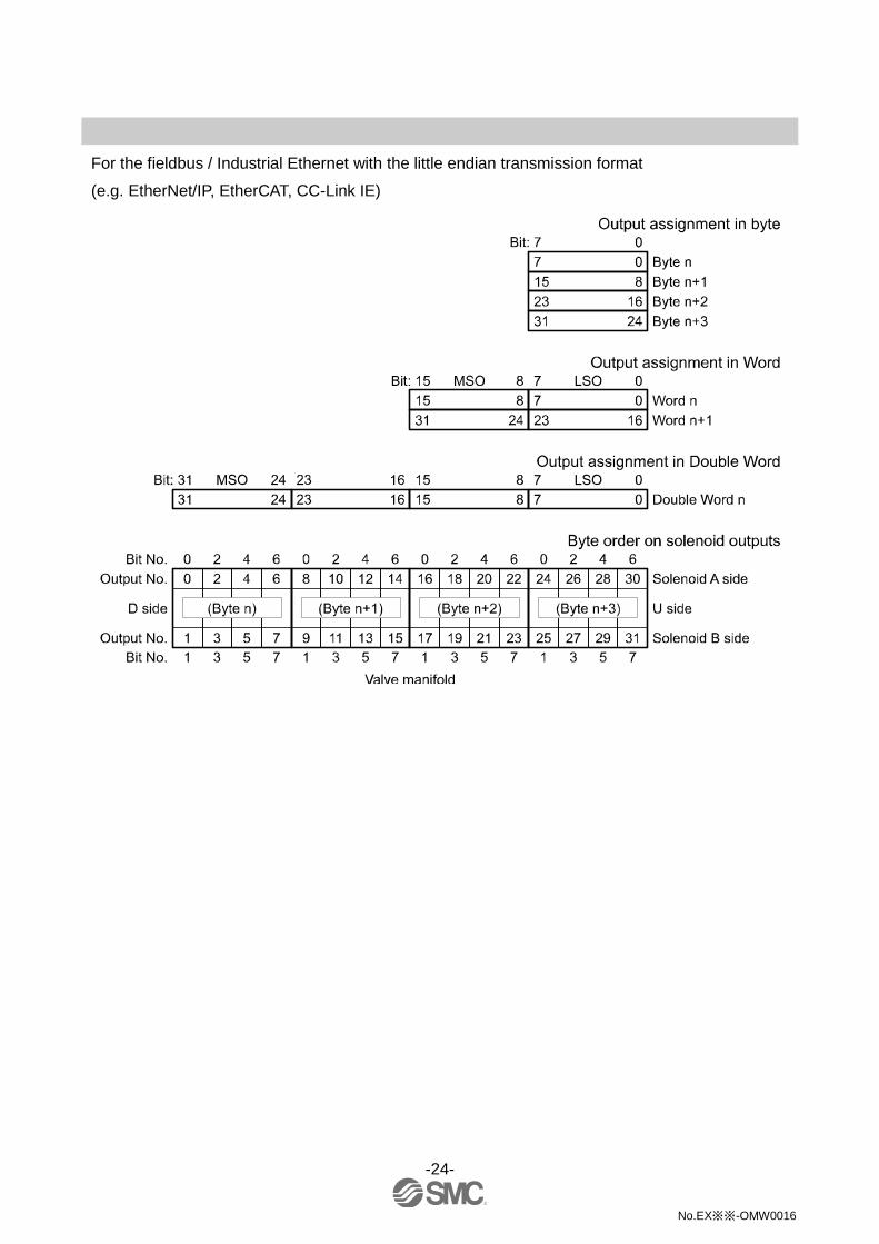
■Output number layout / Process data The process data of this product is designed with byte array base data type, so the byte order when solenoid
output is allocated on the PLC memory is based on the endian type of the transmission format of the IO-Link
master gateway upper communication, either big endian format or little endian format.
The following illustration shows the byte order in each case.
For the fieldbus / Industrial Ethernet with the big endian transmission format
(e.g. Profibus-DP, ProfiNet)
-24-
No.EX※※-OMW0016
For the fieldbus / Industrial Ethernet with the little endian transmission format
(e.g. EtherNet/IP, EtherCAT, CC-Link IE)
-25-
No.EX※※-OMW0016
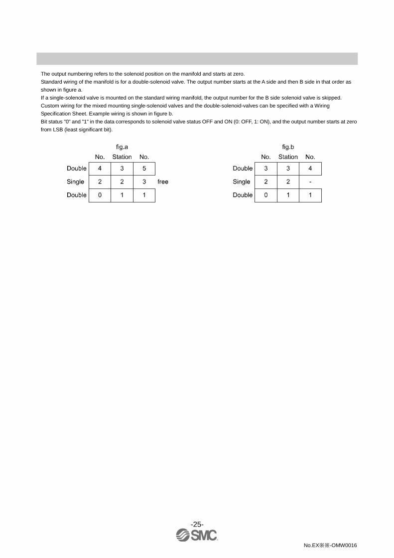
The output numbering refers to the solenoid position on the manifold and starts at zero.
Standard wiring of the manifold is for a double-solenoid valve. The output number starts at the A side and then B side in that order as
shown in figure a.
If a single-solenoid valve is mounted on the standard wiring manifold, the output number for the B side solenoid valve is skipped.
Custom wiring for the mixed mounting single-solenoid valves and the double-solenoid-valves can be specified with a Wiring
Specification Sheet. Example wiring is shown in figure b.
Bit status "0" and "1" in the data corresponds to solenoid valve status OFF and ON (0: OFF, 1: ON), and the output number starts at zero
from LSB (least significant bit).

-26-
No.EX※※-OMW0016
■Input number layout / Process data In this product, Device Status can be added to input data by the switch setting (Page 13).
(Refer to the table below)
Bit offset Index 36 (Device Status)
2 1 0 value Status definition Details
0 0 0 0 In normal
operation -
0 0 1 1 Maintenance
required Output switching counter value over-run
0 1 0 2 Out of
specification
Solenoid power voltage over-run
Solenoid power voltage under-run
0 1 1 3 Function check N/A
1 0 0 4 Failure
- SI unit hardware fault
- SI unit other internal fault
- Output short circuit
- Output open circuit
Bit offset 15 14 13 12 11 10 9 8 7 6 5 4 3 2 1 0
Item Reserved Reserved Device Status
•The process data of this product is byte array type.
The above mapping in word data format is for the case where the transmission order of the upper
communication is little endian.
Please note that the byte order will change in case of big endian.
Refer to the table below for the Endian type of the major upper communication.
Endian type Upper communication protocol
Big-Endian type Such as PROFIBUS and PROFINET
Little-Endian type Such as EtherNET/IP, EtherCAT and CC-Link IE Field.
-27-
No.EX※※-OMW0016
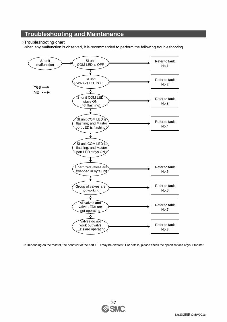
Troubleshooting and Maintenance
○Troubleshooting chart When any malfunction is observed, it is recommended to perform the following troubleshooting.
: Depending on the master, the behavior of the port LED may be different. For details, please check the specifications of your master.
SI unit malfunction
SI unit COM LED is OFF
Valves do not work but valve
LEDs are operating
SI unit PWR (V) LED is OFF
All valves and valve LEDs are not operating
SI unit COM LED stays ON
(not flashing)
Refer to fault
No.2
Energized valves are swapped in byte unit
Group of valves are not working
Refer to fault
No.1
Refer to fault
No.3
Refer to fault
No.5
Refer to fault
No.6
Refer to fault
No.7
Refer to fault
No.8
Yes No
SI unit COM LED is flashing, and Master
port LED is flashing
Refer to fault
No.4
SI unit COM LED is flashing, and Master
port LED stays ON

-28-
No.EX※※-OMW0016
○Troubleshooting table
Fault No.1
Fault Probable cause Recommended error handling Recommended action
SI unit COM
LED is OFF
Defective IO-Link
cable wiring for SI
unit operation
Check the condition of the IO-Link cable
wiring to the SI unit.
Re-tighten the IO-Link cable.
(Replace the cable if it is broken)
Correct the IO-Link cable wiring
layout.
SI unit operating
voltage is not
supplied from the
IO-Link Master
Check the condition of the supply voltage
on the IO-Link Master.
Supply 20 VDC to 30 VDC to the
IO-Link Master.
Fault No.2
Fault Probable cause Recommended error handling Recommended action
SI unit
PWR (V)
LED is OFF
Defective power
cable wiring for the
solenoid valve
Check the condition of the power cable
wiring for the valve.
Re-tighten the power cable.
(Replace the cable if it is broken)
Correct the power cable wiring
layout.
Load voltage for
the valve is not
supplied
Check the condition of the supply voltage
for the valve.
Supply 24 VDC +10%/-5% to
the valves.
Fault No.3
Fault Probable cause Recommended error handling Recommended action
SI unit COM
LED stays
ON
(not flashing)
IO-Link
communication is
inactive
If the Master port LED in which the SI unit is
connected is flashing Green,
Check the IO-Link cable connection.
Make sure there is no broken
wire between the Master and the
SI unit.
(Replace the cable if it is broken)
Correct the IO-Link wiring layout.
Tighten the IO-Link connector
correctly.
If the Master port LED in which the SI unit is
connected is OFF,
Check the IO-Link port configuration on the
Master.
Configure pin 4 to IO-Link for
the IO-Link port of the IO-Link
master.
Configure process data length
properly for the IO-Link port of
the IO-Link master.
(Process data length of IO-Link
port of the master should be
larger than that of the connected
SI unit)
: Depending on the master, the behavior of the port LED may be different. For details, please check the specifications of your master.
-29-
No.EX※※-OMW0016
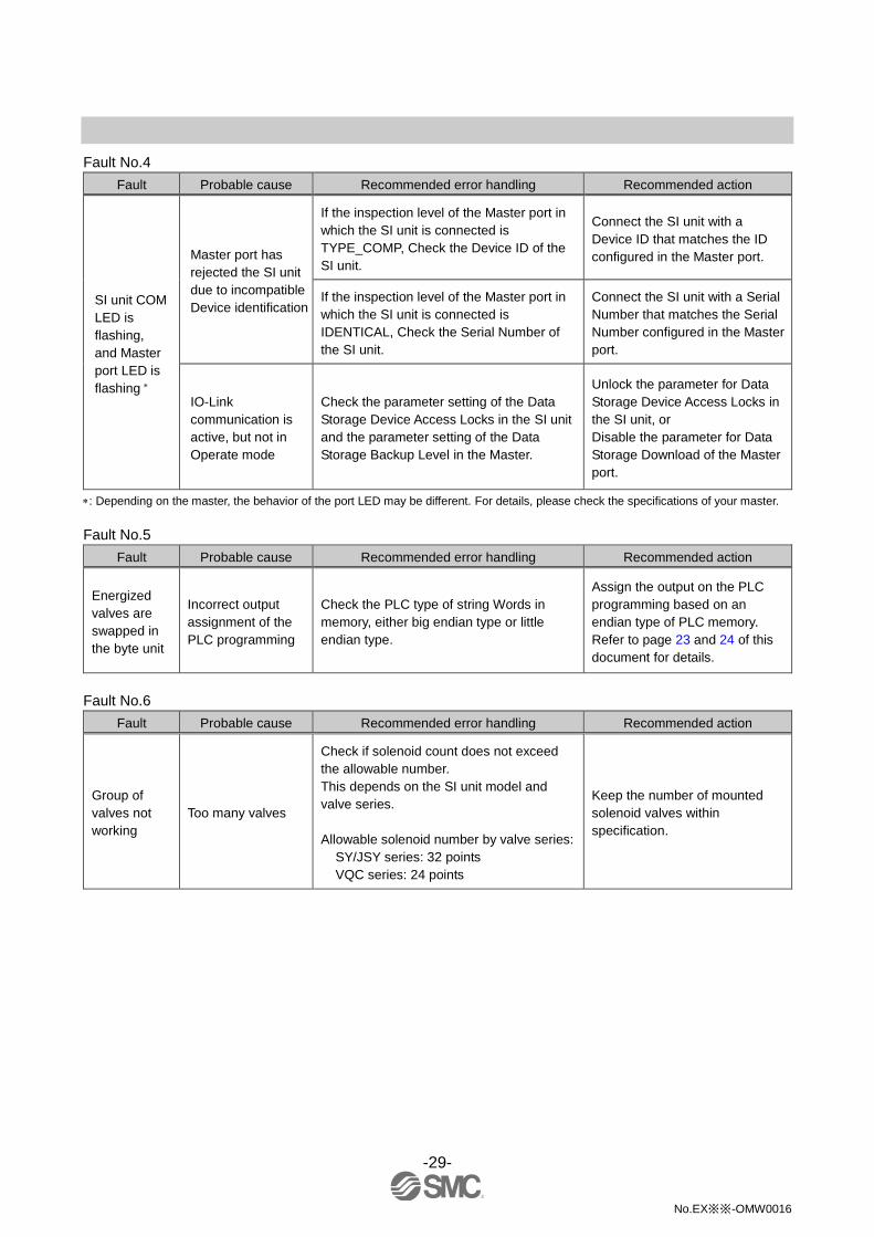
Fault No.4
Fault Probable cause Recommended error handling Recommended action
SI unit COM
LED is
flashing,
and Master
port LED is
flashing
Master port has
rejected the SI unit
due to incompatible
Device identification
If the inspection level of the Master port in
which the SI unit is connected is
TYPE_COMP, Check the Device ID of the
SI unit.
Connect the SI unit with a
Device ID that matches the ID
configured in the Master port.
If the inspection level of the Master port in
which the SI unit is connected is
IDENTICAL, Check the Serial Number of
the SI unit.
Connect the SI unit with a Serial
Number that matches the Serial
Number configured in the Master
port.
IO-Link
communication is
active, but not in
Operate mode
Check the parameter setting of the Data
Storage Device Access Locks in the SI unit
and the parameter setting of the Data
Storage Backup Level in the Master.
Unlock the parameter for Data
Storage Device Access Locks in
the SI unit, or
Disable the parameter for Data
Storage Download of the Master
port.
: Depending on the master, the behavior of the port LED may be different. For details, please check the specifications of your master.
Fault No.5
Fault Probable cause Recommended error handling Recommended action
Energized
valves are
swapped in
the byte unit
Incorrect output
assignment of the
PLC programming
Check the PLC type of string Words in
memory, either big endian type or little
endian type.
Assign the output on the PLC
programming based on an
endian type of PLC memory.
Refer to page 23 and 24 of this
document for details.
Fault No.6
Fault Probable cause Recommended error handling Recommended action
Group of
valves not
working
Too many valves
Check if solenoid count does not exceed
the allowable number.
This depends on the SI unit model and
valve series.
Allowable solenoid number by valve series:
SY/JSY series: 32 points
VQC series: 24 points
Keep the number of mounted
solenoid valves within
specification.

-30-
No.EX※※-OMW0016
Fault No.7
Fault Probable cause Recommended error handling Recommended action
All valves
and valve
LEDs are not
operating
Poor connection
between SI unit and
valve manifold
Check if there are any loose screws making
the connection between the SI unit and the
valve manifold.
Tighten the screws with the
specified tightening torque
(i.e. 0.6 Nm) and make sure
there is no gap between the SI
unit and the valve manifold.
Mismatch polarity
between solenoid
valve and SI unit
output
Check if the solenoid valve common
specification matches the output polarity of
the SI unit.
Match polarity between solenoid
valve and SI unit output.
Defective solenoid
valve
Follow the troubleshooting for the solenoid
valve. Same as left.
Fault No.8
Fault Probable cause Recommended error handling Recommended action
Valves do not
work but
valve LEDs
are operating
Mismatch polarity
between solenoid
valve and SI unit
output
Check if the solenoid valve common
specification matches the output polarity of
the SI unit.
Match polarity between solenoid
valve and SI unit output.

-31-
No.EX※※-OMW0016
■Maintenance Replacement of the SI unit
•Remove the M3 hexagon screws from the SI unit and release the SI unit from the solenoid valve manifold.
•Replace the SI unit.
•Tighten the screws with the specified tightening torque. (0.6 Nm)
Precautions for maintenance
(1) Be sure to switch off the power.
(2) Check there is no foreign matter inside the SI unit.
(3) Check there is no damage and no foreign matter on the gasket.
(4) Be sure to tighten the screws with the specified torque.
If the SI unit is not assembled properly, inside PCBs may be damaged or liquid and/or dust may enter into
the unit.
○Assembly and disassembly of the SI unit

-32-
No.EX※※-OMW0016
Specification
■Specifications
General specifications
Item Specifications
Ambient temperature -10 to +50 oC
Ambient humidity 35 to 85%RH (No condensate)
Ambient temperature for storage -20 to +60 oC
Withstand voltage 500 VAC applied for 1 minute
Insulation resistance 500 VDC, 10 MΩ or more
Operating atmosphere No corrosive gas
Enclosure IP67
Weight 200 g or less
Standards UL/CSA, CE marked (EMC directive/RoHS directive)
Electrical specifications
Item Specifications
Current consumption in
power supply voltage
range
SI unit power supply 18 to 30 VDC
0.1 A max.
Solenoid valve power
supply
22.8 to 26.4 VDC
2.0 A or less
according to the solenoid valve station specification
Solenoid valve
connecting
specification
Output type PNP (negative common) / source
Connected load Solenoid valve with surge voltage suppressor of 24 VDC
and 1.5 W or less (manufactured by SMC)
Insulation Power supply for SI unit – Power Supply for solenoid valve
Residual voltage 0.4 VDC or less

-33-
No.EX※※-OMW0016
IO-Link communication specifications
Item Specifications
Protocol IO-Link version 1.1
Data transmission rate 230.4 Kbps (COM3) or 38.4 kbps (COM2) selectable
Process data minimum
cycle time
EX260-SIL1
(in/out 0/4 bytes, COM3) 0.8 ms
EX260-SIL1
(in/out 0/4 bytes, COM2) 3.4 ms
EX260-SIL1
(in/out 2/4 bytes, COM3) 1 ms
EX260-SIL1
(in/out 2/4 bytes, COM2) 5 ms
Process data length
0 byte input/4 bytes output
2 bytes input/4 bytes output (2 bytes input: Device Status)
(selectable)
Number of outputs 32 outputs
Vendor ID 83 hex
Device ID
EX260-SIL1
(in/out 0/4 bytes, COM3) 158 hex
EX260-SIL1
(in/out 0/4 bytes, COM2) 159 hex
EX260-SIL1
(in/out 2/4 bytes, COM3) 15A hex
EX260-SIL1
(in/out 2/4 bytes, COM2) 15B hex
Applicable solenoid valve series
Solenoid valve series
SY series SY3000, SY5000, SY7000
JSY series JSY1000, JSY3000, JSY5000
VQC series VQC1000, VQC2000, VQC4000, VQC5000

-34-
No.EX※※-OMW0016
■Dimensions
•If a fieldwireable connector is used for the power supply connection, and the SI unit is installed directly to a
solenoid valve manifold, the connector should be 16 mm or less.
If the connector is a larger diameter it will interfere with the clamping face.

No.EX※※-OMW0016
Revision history
4-14-1, Sotokanda, Chiyoda-ku, Tokyo 101-0021 JAPAN Tel: + 81 3 5207 8249 Fax: +81 3 5298 5362 URL http://www.smcworld.com Note: Specifications are subject to change without prior notice and any obligation on the part of the manufacturer. © 2019 SMC Corporation All Rights Reserved