Embed Size (px)
Citation preview

Network Technology Network Technology
SMART INFO DATA MODEL AND PROTOCOL SPECIFICATION
SMART INFO DATA MODEL AND PROTOCOL SPECIFICATION
e-distribuzione S.p.A. – Network Technology
Last update on March 12th 2018
Version 1.3
Firmware release 1.C
Network Technology Network Technology
SMART INFO
DATA MODEL AND PROTOCOL SPECIFICATION
2
This document is the intellectual property of e-distribuzione S.p.A.; reproduction or distribution of its contents in any way or by any means whatsoever is subject to the prior approval of the above mentioned company which will safeguard its rights under the civil and penal codes.
1 SCOPE .............................................................................................................................................................. 4
2 APPLICABILITY ..................................... .......................................................................................................... 5
3 ACRONYMS AND ABBREVIATIONS ........................ ..................................................................................... 6
4 GENERAL INTRODUCTION .............................. .............................................................................................. 7 4.1 SI CONFIGURATION ..................................................................................................................................... 7
4.1.1 SCP download from e-distribuzione web portal ................................................................................... 7 4.1.2 SCP upload on SI ................................................................................................................................ 8 4.1.3 Internal clock setting ............................................................................................................................ 8
4.2 ADDITIONAL BLOCK SUBSCRIPTION .............................................................................................................. 8 4.2.1 Reserved table ..................................................................................................................................... 8
4.3 ADDRESS NEGOTIATION .............................................................................................................................. 8 4.4 LOAD PROFILE MANAGEMENT....................................................................................................................... 8
4.4.1 AB reading load profile ......................................................................................................................... 9 4.5 LEDS MANAGEMENT ................................................................................................................................... 9
4.5.1 Status LED ......................................................................................................................................... 10 4.5.2 AB LED .............................................................................................................................................. 10
4.6 END-USER BUTTON MANAGEMENT ............................................................................................................ 10 4.7 BEHAVIOUR IN CASE OF DISCONNECTION .................................................................................................... 11 4.8 THE PROSUMER CASE ............................................................................................................................... 11
5 APPLICATION PROTOCOL .............................. ............................................................................................ 12 5.1 DEFINITION OF FRAME STRUCTURE ............................................................................................................ 12 5.2 ADDRESSING MODE .................................................................................................................................. 12
5.2.1 SI codes in Nack/Ack messages ....................................................................................................... 13
6 USE CASES ................................................................................................................................................... 15 6.1 SCP UPLOAD ........................................................................................................................................... 16
6.1.1 Preparation of script upload ............................................................................................................... 16 6.1.2 Write script row sequence .................................................................................................................. 16
6.2 INTERNAL CLOCK SETTING ......................................................................................................................... 17 6.1 FORMAT FILE SYSTEM COMMAND .............................................................................................................. 18 6.2 REBOOT COMMAND ................................................................................................................................... 18 6.3 CHECK POWERLINE LINK COMMAND .......................................................................................................... 19
6.3.1 Prepare for Powerline Link Test......................................................................................................... 21 6.4 SMART METER LINK CHECK ................................................................................................................... 2222 6.5 AB ENROLMENT ................................................................................................................................... 2323 6.6 ADDRESS REQUEST .................................................................................................................................. 23 6.7 ADDITIONAL BLOCK REQUESTS DATA ......................................................................................................... 24 6.8 EVENT SUBSCRIPTION/DELETING ........................................................................................................... 2525 6.9 EVENT GENERATION BY SI ..................................................................................................................... 2525 6.10 AB ASKS FOR LOAD PROFILE LOG .......................................................................................................... 2626 6.11 DIAGNOSTIC CLEAR .............................................................................................................................. 2828 6.12 PUBLICATION OF DEVICE CONFIGURATION INFORMATION ......................................................................... 2929 6.13 APPLICATION LED STATUS COMMAND ................................................................................................... 2929
7 FIRMWARE UPDATE ................................... ............................................................................................. 3030 7.1 DATA FLOW EXAMPLE INCLUDING ERROR RECOVERY ............................................................................... 3131
8 DATA MODEL ........................................ .................................................................................................... 3232 8.1 DATA FORMAT ...................................................................................................................................... 3232 8.2 DATA TABLES ....................................................................................................................................... 3333
8.2.1 Table 100 ....................................................................................................................................... 3333 8.2.2 Table 101 ....................................................................................................................................... 3434
9 AUTOMATIC DIAGNOSTIC FUNCTION ..................... .............................................................................. 3636 9.1 INTRODUCTION ..................................................................................................................................... 3636

Network Technology Network Technology
SMART INFO
DATA MODEL AND PROTOCOL SPECIFICATION
3
This document is the intellectual property of e-distribuzione S.p.A.; reproduction or distribution of its contents in any way or by any means whatsoever is subject to the prior approval of the above mentioned company which will safeguard its rights under the civil and penal codes.
9.2 PERIODIC CHECK ENGINE ..................................................................................................................... 3636 9.3 REAL-TIME DIAGNOSTIC ........................................................................................................................ 3636 9.4 DIAGNOSTIC REGISTERS AND RELEVANT MANAGEMENT ........................................................................... 3737 9.5 EVENTS MANAGEMENT .......................................................................................................................... 3838 9.6 NOTIFICATION TYPES ............................................................................................................................ 3838 9.7 NOTIFICATION LIST ................................................................................................................................ 3939
9.7.1 Notifications with only informative content ..................................................................................... 4142 9.7.2 Notifications relevant to errors preventing SI operation ................................................................. 4142 9.7.3 Notifications relevant to not fatal errors or operating conditions decay signaling .......................... 4445 9.7.4 Notification relevant to faults preventing SI operation ................................................................... 4546 9.7.5 Notifications relevant to issues on Power Line communication ..................................................... 4647 9.7.6 Notification of issues on communication with the Host .................................................................. 4950

Network Technology Network Technology
SMART INFO
DATA MODEL AND PROTOCOL SPECIFICATION
4
This document is the intellectual property of e-distribuzione S.p.A.; reproduction or distribution of its contents in any way or by any means whatsoever is subject to the prior approval of the above mentioned company which will safeguard its rights under the civil and penal codes.
1 Scope This document describes the functional requirements of Smart Info. Smart Info is an indoor device enabling the communication with LV e-distribuzione Smart Meters via power line Band A, finalised to the collection of metering data.
In case of prosumers, Smart Info can be interfaced with both the consumption and production meters at the same time.
Network Technology Network Technology
SMART INFO
DATA MODEL AND PROTOCOL SPECIFICATION
5
This document is the intellectual property of e-distribuzione S.p.A.; reproduction or distribution of its contents in any way or by any means whatsoever is subject to the prior approval of the above mentioned company which will safeguard its rights under the civil and penal codes.
2 Applicability Smart Info is applicable to e-distribuzione Low Voltage Smart Meters either single phase or three-phase, connected to the e-distribuzione SMCC. Furthermore the following conditions need to be applied in order to allow communication between Smart Info and the SM:
• SM is operational, reachable from the SMCC and coupled with the Smart Info • Smart Info is operational, installed on the same electric network monitored by SM to be
connected with • No noises on PLC Band A1 • No isolation transformer installed between the SM and Smart Info • In case of a three-phase meter, the T phase shall be used to supply Smart Info. This is the
phase that supports the communication with the meter.
1 As defined by EN50065, UL frequency of Band A is from 9 KHz to 95 KHz. This frequency band is limited to energy providers.

Network Technology Network Technology
SMART INFO
DATA MODEL AND PROTOCOL SPECIFICATION
6
This document is the intellectual property of e-distribuzione S.p.A.; reproduction or distribution of its contents in any way or by any means whatsoever is subject to the prior approval of the above mentioned company which will safeguard its rights under the civil and penal codes.
3 Acronyms and abbreviations AB: Additional block. The external module connected with the SI via USB connection.
DB: Data Base
DST: Daylight Saving Time
DUT: Device Under Test
LV: Low Voltage
NID: Neuron Identifier
PLC : Power Line Carrier
POD: Point of Delivery
RTC: Real Time Clock
SCP: The script needed to configure SI and enable the communication with the SM
SI: Smart Info. The device described in this specification at functional level.
SM: Smart Meter
SMCC: Smart Metering Control Center (Back Office)

Network Technology Network Technology
SMART INFO
DATA MODEL AND PROTOCOL SPECIFICATION
7
This document is the intellectual property of e-distribuzione S.p.A.; reproduction or distribution of its contents in any way or by any means whatsoever is subject to the prior approval of the above mentioned company which will safeguard its rights under the civil and penal codes.
4 General introduction The SI implements a secure interface between LV e-distribuzione SMs and ABs provided by third parties.
One SI can communicate with only one meter - exclusively in case a separate production meter is installed, Smart Meter can communicate with this too (see also 4.8 for more details) - through the PLC Band A and the reserved e-distribuzione SM protocol. SI and the meter intended to provide metering data have to be associated one each other by means of a specific procedure (see section 4.1 SI configuration) otherwise the communication is not allowed. SI shall be installed on the same power line of its relevant meter.
SI provides SM data with a public data model on two USB interfaces emulating two serial interfaces. It usually receives data update from the SM every 15 minutes. The update frequency is subject to SMCC operation and specific physical conditions on the power line.
The two USB ports can support contemporary connection with two different ABs, with the only restriction that the Client Applications have different Application ID.
In the following paragraphs, the relevant procedures and functionalities are described.
4.1 SI configuration SI must be properly configured in order to be allowed to communicate with a SM. The configuration procedure allows SI to be coupled with a specific SM identified by the POD. This procedure foresees three steps: 1. SCP download from a dedicated section of the e-distribuzione web portal 2. SCP upload on SI 3. Internal clock setting It requires that:
• the user (e.g. owner of the POD or its authorised third party) is registered to the e-distribuzione web portal and
• the configuration service “Configurazione MOME/Smart Info” is activated: once registration is completed, the user can activate this service selecting it among those suggested by the web portal.
4.1.1 SCP download from e-distribuzione web portal
Once the user is registered to the web portal and the service is activated, it will be able to login and download the SCP for the SM associated to the POD, according to the user profile allowances, as described: 0.1. Selecting a POD from the list of PODs (more than one POD in case of multiple households or
prosumers). 0.2. Providing the NID of the SI to be associated to the selected POD (SM). 0.3. Selecting the type of configuration: Standard or Prosumer. 0.4. Launching the commissioning procedure that will create the association between the selected
POD and the SI. 0.5. Download the SCP.

Network Technology Network Technology
SMART INFO
DATA MODEL AND PROTOCOL SPECIFICATION
8
This document is the intellectual property of e-distribuzione S.p.A.; reproduction or distribution of its contents in any way or by any means whatsoever is subject to the prior approval of the above mentioned company which will safeguard its rights under the civil and penal codes.
4.1.2 SCP upload on SI
Once SCP is downloaded, it must be uploaded on SI via the USB. The AB has to pass the SCP file row by row. The detailed procedure is defined in 6.16.1.
4.1.3 Internal clock setting
This command updates the current date-time of the SI, ensuring no discrepancy in its internal RTC, until the periodic CLOCK update is received from the SM system. The value of the internal clock is important to assign the correct timestamps to the data received from the SM. The detailed procedure is defined in 6.2.
In order to check that the SCP installation is successful, it is advisable that the AB reads the POD register (see 8.2.2) and verify that the value actually corresponds to the POD number.
4.2 Additional Block subscription An enrolment process is implemented enabling AB’s applications to use SI functionalities. Enrolment implies that each AB application gets an address to exchange messages with SI. A reserved table is used to define enrolment parameters for each application.
The detailed procedure is defined in 6.3.
4.2.1 Reserved table
An AB application must enrol itself accepting an address from SI. That address will be used for all the communications with SI.
The authorized ApplicationID is PCMC000000XXXXXX (where X has to be exactly the character “X”).
4.3 Address negotiation An address negotiation procedure must be implemented in order to allow an AB to get the address to exchange information with SI. This procedure is defined in 6.6.
4.4 Load profile management SI stores at least 10 days of Energy History (i.e. collection of energy data samples in a time period), the granularity being defined by the parameter “Ti” (Integration Time for Load Power – by default 15 minutes – Row 24 of Section 1).
Every time SI receives a Total Active Energy sample (Row 6 in Section 0) this value is stored and the Wh difference with the previous one is calculated and assigned to the corresponding sample.
For the Load Profile Management: • Resources required: Every sample is 2 bytes (Wh). By default a sample is collected every 15
minutes, for a maximum of 960 samples for consumed energy, and 960 samples for produced energy. Thus, with 30 minute sampling time, 20 days could be stored.
• Values to be stored: Date and time of the last sample, the samples, the Ti value.
All time references are in winter time notation. The user application must operate a summer (DST) conversion if required.

Network Technology Network Technology
SMART INFO
DATA MODEL AND PROTOCOL SPECIFICATION
9
This document is the intellectual property of e-distribuzione S.p.A.; reproduction or distribution of its contents in any way or by any means whatsoever is subject to the prior approval of the above mentioned company which will safeguard its rights under the civil and penal codes.
4.4.1 AB reading load profile
When the load profile is required by the AB application, every message shall be structured in “blocks”, every block being a message of 6 samples (except for the last block that can be shorter).
Request and Response procedure for Load Profile Management: • AB sends a “Log delivery command” asking for a certain “type” of log.
Types implemented are: o Type 4: Energy withdrawn from the network by the customer o Type 7: Energy fed into the network by the customer o Type 11: Energy Produced by the customer (prosumer case only)
• SI response, in “Log delivery Resp ”, includes: o Date and Time of the first sample (the older one) of the log o Total number of samples o Integration time (Ti) o Log Type o Absolute value of the first sample in the log
• SI starts to send log data starting from the oldest sample to the lastly received. Data are organised in data “blocks”. Every datum – 9-byte-long – is coded in big-endian structure. Every block contains:
o Log Type o Identification number of the current block o Total number of blocks o Records (Samples)
Each not valid sample, is saved by SI in the load profile as “0xFFFFFFFF”.
The data structure of these messages is better defined in 6.10.
4.5 LEDs management
The SI manages 2 LEDs:
- The Status LED
- The AB LED
The Status LED shows the SI operating status.
The AB LED status can be set by the AB.

Network Technology Network Technology
SMART INFO
DATA MODEL AND PROTOCOL SPECIFICATION
10
This document is the intellectual property of e-distribuzione S.p.A.; reproduction or distribution of its contents in any way or by any means whatsoever is subject to the prior approval of the above mentioned company which will safeguard its rights under the civil and penal codes.
4.5.1 Status LED
Status LED is a bicolour LED (e.g. green/red) coded according to the following table
LED Status Case
Green SI has received at least one data from SM
Red or Switched Off Error (SI fault)
Green/Red blinking slow SI has never received data from SM
Green/Red blinking fast Possible overload: instant power exceeds contractual power
4.5.2 AB LED
The AB LED is a bicolour LED (e.g. yellow/green). The status of this LED can be set by the AB, by using the command described in section 6.13, according to the encoding detailed in the following table:
Code LED Status
0 OFF (default)
1 Yellow blinking slow
2 Yellow blinking fast
3 Green blinking slow
4 Green blinking fast
5 Green ON
6 Yellow ON When Smart Info is powered for the first time, the status of this LED is set to the default value (i.e. OFF, coded 0). 4.6 End-user Button Management
The end-user button can be used by AB requiring end-user interaction.
SI will manage the button operation by the end-user providing to the AB with a filtered information.
The end-user can press the button in fast sequence, and the SI will update the “Button status” field in Section 0 Row 106 with a value indicating the number of the button pressures in the fast pressures sequence operated by the end-user.
The SI provides a direct feedback to the end-user trough the “Application LED” (ref to section 4.5.2), by turning the Application LED off when the button is pressed; then the Application LED is turned ON in green colour each time the button is pressed in the fast-pressures sequence.
At the end of end-user operations, the Application LED is managed by the SI, according to the requests from the AB (as described in section 4.5.2). The LED status in place before the end-user pressure is not restored.
Network Technology Network Technology
SMART INFO
DATA MODEL AND PROTOCOL SPECIFICATION
11
This document is the intellectual property of e-distribuzione S.p.A.; reproduction or distribution of its contents in any way or by any means whatsoever is subject to the prior approval of the above mentioned company which will safeguard its rights under the civil and penal codes.
4.7 Behaviour in case of disconnection In case both SI and the AB get powered off, the connection between the 2 devices shall be automatically (without customer interaction) restored at power on. To this extent, the AB must operate address negotiation (see 4.3) and events subscription (see 6.8) procedures. The Application enrolling activity can be avoided, because SI has recorded the ApplicationID.
If only the AB gets powered off, it must repeat the address negotiation and events subscription procedures. If only SI gets powered off, the connected AB must repeat address negotiation and events subscription procedures. When SI gets powered off, the DB Section 0 will be recorded, but if power off time duration exceeds 2 days, data could be lost.
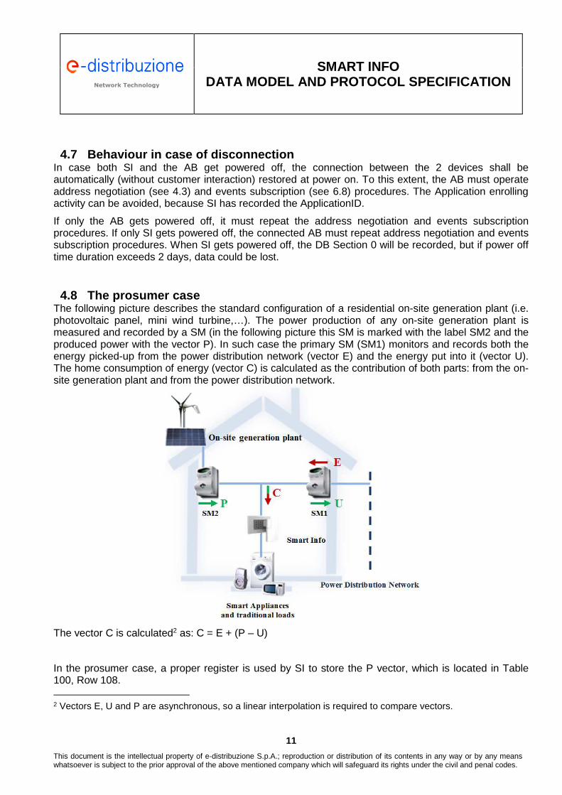
4.8 The prosumer case The following picture describes the standard configuration of a residential on-site generation plant (i.e. photovoltaic panel, mini wind turbine,…). The power production of any on-site generation plant is measured and recorded by a SM (in the following picture this SM is marked with the label SM2 and the produced power with the vector P). In such case the primary SM (SM1) monitors and records both the energy picked-up from the power distribution network (vector E) and the energy put into it (vector U). The home consumption of energy (vector C) is calculated as the contribution of both parts: from the on-site generation plant and from the power distribution network.
The vector C is calculated2 as: C = E + (P – U)
In the prosumer case, a proper register is used by SI to store the P vector, which is located in Table 100, Row 108. 2 Vectors E, U and P are asynchronous, so a linear interpolation is required to compare vectors.

Network Technology Network Technology
SMART INFO
DATA MODEL AND PROTOCOL SPECIFICATION
12
This document is the intellectual property of e-distribuzione S.p.A.; reproduction or distribution of its contents in any way or by any means whatsoever is subject to the prior approval of the above mentioned company which will safeguard its rights under the civil and penal codes.
5 Application protocol A client-server model is applied for the application protocol, where SI acts as server.
In normal conditions the client asks the server for the needed information and the server replies. A number of exceptions are managed, like spontaneous messages from SI to the external application in case of some defined events.
The channel is used as a serial connection, full duplex. Standard configuration: 57600 baud, 8, n; 1.
5.1 Definition of frame structure The application packet (named “DATA” in the following) is encapsulated in the structure below:
Start char (1 byte) DataLen (1byte) DATA (variable length) Checksum (2 bytes)
STX 0xF7 (247) 1-60 ADDR+PAYLOAD value • DataLen: length of “DATA” in bytes • DATA: This field is composed by address (ADDR) and payload (PAYLOAD), its maximum length is
60 bytes, with the only exception of SCP upload operations (please refer to section 4.1.2 and 6.1) where the maximum length of 60 bytes can be exceeded.
• Checksum: sum mod 2^16 of “DATA” No specific inter-byte time control is required, but if all the bytes required are not received within 40 ms after STX, the message has to be considered not valid (at default baud rate 57600 b/s).
The frame structure only encapsulates the field “DATA”. Possible structures of this field are described in the following paragraphs.
5.2 Addressing mode Request:
SOURCE_ADDRESS DESTINATION_ADDRESS (127) ATTR Request Data[..]
Response:
SOURCE_ADDRESS (127) DESTINATION_ADDRESS ATTR Response[..]
EVENT NOTIFICATION: Event:
SOURCE_ADDRESS (127) DESTINATION_ADDRESS ATTR Spont Data[..]

Network Technology Network Technology
SMART INFO
DATA MODEL AND PROTOCOL SPECIFICATION
13
This document is the intellectual property of e-distribuzione S.p.A.; reproduction or distribution of its contents in any way or by any means whatsoever is subject to the prior approval of the above mentioned company which will safeguard its rights under the civil and penal codes.
Ack/Nack:
SOURCE_ADDRESS DESTINATION_ADDRESS (127) ATTR Result_code (1 byte)
The Server (SI) address is reserved and it is “127”. Clients negotiate the address with the Server; admitted addresses are [1,126] . Address “0” means “not assigned address”. Before the enrolment, it is used by the Client during the communications with the Server. The address “255” is used as broadcast address. Addresses [128,254] are reserved. All messages from external application to SI have even ATTR codes, while all messages from SI to external application have odd ATTR codes. The Application Protocol sets out a time-out of 2 seconds for response messages (RENSPONSE ACK/NACK): • After 2 seconds without receiving a RESPONSE ACK/NACK the subject issuing the request (Client
or Server depending on the use case) must retry to issue the request (i.e. an event update is sent three times by SI if the AB does not answer ACK).
• After 2 retries without receiving a RESPONSE ACK/NACK the message will be considered lost and the request failed.
5.2.1 SI codes in Nack/Ack messages
SI_Ack Result codes ATTR Param1: 1byte
SI_ACK 251 Result_code: 0x00 Positive acknowledgement SI_Nack Result codes
ATTR Param1: 1byte
SI_NACK 255
Result_code: 0x00 Message not correct 0x01 ATTR not valid 0x02 not valid Parameter 0x03 Device not Enrolled 0x04 Datum not valid or Unavailable 0x05 Log not available 0x06 Buffer not available 0x07 Over limit transmissions 0x08 SI not commissioned yet 0x09 Auth/encryption Error 0x0A Target not present in configuration
APPL Ack Result codes
ATTR Param1: 1byte

Network Technology Network Technology
SMART INFO
DATA MODEL AND PROTOCOL SPECIFICATION
14
This document is the intellectual property of e-distribuzione S.p.A.; reproduction or distribution of its contents in any way or by any means whatsoever is subject to the prior approval of the above mentioned company which will safeguard its rights under the civil and penal codes.
APPL_ACK 252 Result_code: 0x00 Positive acknowledgement APPL_Nack Result codes
ATTR Param1: 1byte
APPL_NACK 254
Result_code: 0x00 Message not correct 0x01 ATTR not valid 0x02 not valid Parameter 0x03 stop sequence 0x04 buffer not available

Network Technology Network Technology
SMART INFO
DATA MODEL AND PROTOCOL SPECIFICATION
15
This document is the intellectual property of e-distribuzione S.p.A.; reproduction or distribution of its contents in any way or by any means whatsoever is subject to the prior approval of the above mentioned company which will safeguard its rights under the civil and penal codes.
6 Use Cases In this section use cases are reported. In the following flow diagram the standard procedure to establish data communication between an AB and SI is represented.
Hereafter an example of the messages exchanged between SI and the AB is presented:
Timestamp Source Dest Attr Payload[hex] (payload_length)
12:06:09.175 000 127 072 ENR_REQ 50 43 4D 43 30 30 30 30 30 30 58 58 58 58 58 58 01 00 00 00 00 00 00 00 00 00 00 00 02 00 00 00 00 00 00 00 00 00 00 00 00 00 00 00 (44)
12:06:09.184 127 000 073 ENR_RES 50 43 4D 43 30 30 30 30 30 30 58 58 58 58 58 58 02 (17)
12:06:10.737 000 127 070 ADDR_REQ 50 43 4D 43 30 30 30 30 30 30 58 58 58 58 58 58 (16)
12:06:10.741 127 000 071 ADDR_RES 50 43 4D 43 30 30 30 30 30 30 58 58 58 58 58 58 04 (17)
12:06:18.357 004 127 002 RD_REQ 00 06 (2)
12:06:18.361 127 004 003 RD_RES 00 06 00 08 DF 36 04 0B 0E 0B 0C 1B (12)
12:06:30.948 004 127 002 RD_REQ 01 16 (2)
12:06:30.953 127 004 003 RD_RES 01 16 50 4F 44 43 4C 49 45 4E 54 45 00 00 00 00 00 14 0A 0E 0F 1C 13 (23)
12:07:04.503 004 127 074 EVT_SUBS 01 00 69 (3)
12:07:04.508 127 004 251 SI_ACK 00 (1)
12:07:04.561 127 004 081 DATA_UPD 01 00 69 0B 34 (5)
During the enrolment procedure either SMCC or SI verifies the Application ID provided by AB to allow communication, as described in6.5.
SI assigns an address to the AB, as described in 6.6.
The AB subscribes to an event to automatically receive data update, as described in 6.8. SI answers with the actual value of the related data as described in 6.9.
When data changes, SI sends the update, as described in 6.9.
AB SI
Enrollment request
Enrollment response
Address request
Address response
Event subscription
Event generation
Event response

Network Technology Network Technology
SMART INFO
DATA MODEL AND PROTOCOL SPECIFICATION
16
This document is the intellectual property of e-distribuzione S.p.A.; reproduction or distribution of its contents in any way or by any means whatsoever is subject to the prior approval of the above mentioned company which will safeguard its rights under the civil and penal codes.
6.1 SCP upload The SCP upload sequence entails two consecutive phases:
• Preparation of script upload (Subcode 000) • Actual upload of script content (Subcode 050)
Note: Before downloading the configuration script, a SET_INTERNAL_DATE_TIME command has to be sent to ensure a valid internal clock.
6.1.1 Preparation of script upload
This message allows enabling a script upload. This is the first message to be sent before the sequence of WRITE SCRIPT ROW messages are actually performed. Request
SOURCE_ADDRESS DESTINATION_ADDRESS ATTR Param: 1 byte
0 127 SI_SERVICE_CODE 000 Subcode: 000 Enable script upload
Response
SOURCE_ADDRESS DESTINATION_ADDRESS ATTR Parm1
(8 bytes) Param2 (9 bytes)
Param3 (6 bytes)
Param4 (8 bytes)
Param5 (1 bytes)
Param6 (1 bytes)
Param7 (6 bytes)
127 Address ID SI
_SERVICE_CODE 000
SI release (ASCII format)
reserved NID SI Modem
SW stack release
SI type reserved Internal clock
Note: The response message returns the SI release data, as follows:
• “SI release” is in ASCII format, it defines the program name (6 bytes) + major_release (1 byte) + minor_release (1 byte).
• Param2 is reserved.
• “NID SI” is the SI identification code printed on its label. It is showed as an HEX string.
• “Modem sw stack release”: it defines the modem software stack program name (6 bytes) + major_release (1 byte) + minor_release (1 byte).
• “SI type” defines the type of Modem.
• Param6 is reserved.
• Internal clock is the value of the current internal clock set in the dd/mm/YY (from 2000) hh:mm:ss format
6.1.2 Write script row sequence
This message allows writing a single row of a SCP file. Each line of the script must be sent iteratively, waiting for the acknowledgement for each command. If the sequence fails, the AB shall send the script from the beginning and the preparation of script upload shall also be re-executed (ref. to section 6.1.1).

Network Technology Network Technology
SMART INFO
DATA MODEL AND PROTOCOL SPECIFICATION
17
This document is the intellectual property of e-distribuzione S.p.A.; reproduction or distribution of its contents in any way or by any means whatsoever is subject to the prior approval of the above mentioned company which will safeguard its rights under the civil and penal codes.
Request
SOURCE_ADDRESS DESTINATION_ADDRESS ATTR Param: 1 byte Param2: variable
length
0 127 SI_SERVICE_CODE 000 Subcode: 050 Write Script Row
Bytes stream of the current SCP row
Note: The configuration script is a text file where each row is an ASCII string which represents a stream of bytes in hexadecimal encoding. Frome each string the last CR/LF character shall be removed. The bytes values are represented by every hexadecimal character pairs.
Lines which begins with the characters “//” are comments, and have not to be sent.
As an example, the following 30-characters string: “040F0B04651901FF000101010102FF” from the script, has to be considered as a stream of 15 bytes: � {0x04, 0x0F, 0x0B, 0x04, 0x65, 0x19, 0x1F, 0xFF, 0x00, 0x01, 0x01, 0x01, 0x01, 0x02, 0xFF}
SI Ack/Nack
SOURCE_ADDRESS DESTINATION_ADDRESS ATTR Param1: 1 byte
127 Address ID SI_ACK 251
or SI_NACK 255
Result_code (see legend 5.2.1)
6.2 Internal clock setting This command updates the current date-time of the SI. It removes any discrepancy with its internal RTC, until the periodic CLOCK update is received from the SM system. The value of the internal clock is important to assign the correct timestamps to the data received from the SM.
Request
SOURCE_ADDRESS DESTINATION_ADDRESS ATTR Param: 1 byte Param2: 6 bytes
0 127 SI_SERVICE_CODE 000 Subcode: 008 SET internal
date/time
YY_from2000/MM/DD hh:mm:ss
SI Ack/Nack
SOURCE_ADDRESS DESTINATION_ADDRESS ATTR Param1: 1 byte
127 Address ID SI_ACK 251
or SI_NACK 255
Result_code (see legend 5.2.1)

Network Technology Network Technology
SMART INFO
DATA MODEL AND PROTOCOL SPECIFICATION
18
This document is the intellectual property of e-distribuzione S.p.A.; reproduction or distribution of its contents in any way or by any means whatsoever is subject to the prior approval of the above mentioned company which will safeguard its rights under the civil and penal codes.
6.1 Format File System command This command formats the File System so that SI device configurations are recovered to the factory defaults superseding possible customizations introduced by any previously uploaded script. The effectiveness of the command occurs at the next reboot/power up. So, the AB should in principle consider to issue a subsequent 'reboot' command (refer to section 6.2). This command shall be used according to firmware update requirements, provided along with firmware release note.
Format File System Request
SOURCE_ADDRESS DESTINATION_ADDRESS ATTR Param: 1 byte
0 127 SI_SERVICE_CODE 000 Subcode: 002 Format FS
NOTE: Use 0x00 as source address.
Format File System Response (Ack/Nack)
SOURCE_ADDRESS DESTINATION_ADDRESS ATTR Param1: 1 byte
127 0 SI_ACK 251
or SI_NACK 255
Result_code (see legend 5.2.1)
NOTE: After the Format FS it is recommended to issue a “Diagnostic Clear” command (ref. to section 6.11). 6.2 Reboot command
This command forces the SI device to reboot (software reset).
Reboot Request
SOURCE_ADDRESS DESTINATION_ADDRESS ATTR Param: 1 byte
0 127 SI_SERVICE_CODE 000 Subcode: 007 Reboots the
device
NOTE: Use 0x00 as source address.
Reboot Response SOURCE_ADDRESS DESTINATION_ADDRESS ATTR Param1: 1 byte
127 0 SI_ACK 251
or SI_NACK 255
Result_code (see legend 5.2.1)
NOTE: After this command it's necessary to download the 'configuration script' to get the SI fully functional (see section 6.1).

Network Technology Network Technology
SMART INFO
DATA MODEL AND PROTOCOL SPECIFICATION
19
This document is the intellectual property of e-distribuzione S.p.A.; reproduction or distribution of its contents in any way or by any means whatsoever is subject to the prior approval of the above mentioned company which will safeguard its rights under the civil and penal codes.
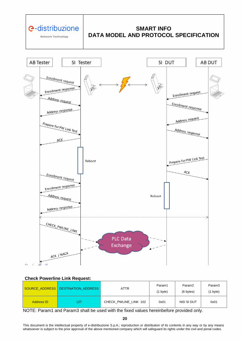
6.3 Check Powerline Link command This command can be used to verify the proper functionality of the power line modem of a SI device. Two SI devices are required: the device under test (SI DUT) and another one acting as Tester (SI Tester). Both are locally connected with their respective AB and communicate each other through the same power line. The following steps are pre-requisites for the test-procedure:
• The AB connected to the SI DUT: 1. Issue an Enrollment request (ref. to section 6.5) 2. Issue an Address request (ref. to section 4.3) 3. Issue a Prepare for “PW Link Test” command (ref. section 6.3.1)
• The AB connected to the SI Tester: 1. Issue an Enrollment request (ref. to section 6.5) 2. Issue an Address request (ref. to section 4.3) 3. Issue a Prepare for “PW Link Test” command (ref. section 6.3.1) 4. Issue an Enrollment request (ref. to section 6.5) 5. Issue an Address request (ref. to section 4.3)
After the SI devices have gone through the hereinbefore listed commands sequence, the AB Tester can issue the “Check Power Link” command. The SI Tester will then reply with a SI_ACK in case the test is successful or with a SI_NACK, according to these cases:
• 0x02 (Parameter Error): in case the command has been issued specifying improper parameters;
• 0x04 (No answer from DUT): In case the SI Tester has not been able to receive valid answer from DUT
NOTE: Both SI Tester and SI DUT shall be upgraded to the same firmware release.
After this procedure has been applied it's necessary to download the 'configuration script' to get the SI devices fully functional (see section 6.1). This applies to both the SI DUT and to the SI Tester.
Network Technology Network Technology
SMART INFO
DATA MODEL AND PROTOCOL SPECIFICATION
20
This document is the intellectual property of e-distribuzione S.p.A.; reproduction or distribution of its contents in any way or by any means whatsoever is subject to the prior approval of the above mentioned company which will safeguard its rights under the civil and penal codes.
Check Powerline Link Request:
SOURCE_ADDRESS DESTINATION_ADDRESS ATTR Param1
(1 byte)
Param2
(6 bytes)
Param3
(1 byte)
Address ID 127 CHECK_PWLINE_LINK 102 0x01 NID SI DUT 0x01
NOTE: Param1 and Param3 shall be used with the fixed values hereinbefore provided only.

Network Technology Network Technology
SMART INFO
DATA MODEL AND PROTOCOL SPECIFICATION
21
This document is the intellectual property of e-distribuzione S.p.A.; reproduction or distribution of its contents in any way or by any means whatsoever is subject to the prior approval of the above mentioned company which will safeguard its rights under the civil and penal codes.
Check Powerline Link ACK:
SOURCE_ADDRESS DESTINATION_ADDRESS ATTR Param1: 1 byte
127 Address ID SI_ACK 251 Result_code
(see legend 5.2.1)
Check Powerline Link NACK: SOURCE_ADDRESS DESTINATION_ADDRESS ATTR Param1: 1 byte
127 Address ID SI_NACK 255 0x02 (Parameter Error)
0x04 (No answer from DUT)
6.3.1 Prepare for Powerline Link Test
This command shall be used on the SI device under test (SI DUT), before issuing the command described in section 6.3 “Check Powerline Link command” on the SI acting as tester.
Prepare for Powerline Link Test Request:
SOURCE_ADDRESS DESTINATION_ADDRESS ATTR Param1
(1 byte)
Param2
(1 bytes)
0 127 SI_SERVICE_CODE 000 Subcode: 0x0D (Prepare for Powerline Link test)
0x04
NOTE: Param2 shall be used with the fixed value hereinbefore provided only.
Prepare for Powerline Link Test ACK:
SOURCE_ADDRESS DESTINATION_ADDRESS ATTR Param1: 1 byte
127 0 SI_ACK 251 Result_code
(see legend 5.2.1)
Prepare for Powerline Link Test NACK: SOURCE_ADDRESS DESTINATION_ADDRESS ATTR Param1: 1 byte
127 0 SI_NACK 255 0x02 (Parameter Error)

Network Technology Network Technology
SMART INFO
DATA MODEL AND PROTOCOL SPECIFICATION
22
This document is the intellectual property of e-distribuzione S.p.A.; reproduction or distribution of its contents in any way or by any means whatsoever is subject to the prior approval of the above mentioned company which will safeguard its rights under the civil and penal codes.
6.4 Smart Meter Link check This command can be used in a production environment to verify the actual effectiveness of the powerline communication link between the SI device and the target SM. Both links with the primary SM and the production SM can be verified. This command can be assimilated to a “ping” command from SI device to the target SM. A NACK response with code 0x04 indicates that it has not been possible to establish a communication link with the specified target Smart Meter (primary or production meter). A NACK response with code 0x0A indicates that the target SM has not been specified in the SI uploaded configuration (e.g.: when a production SM is specified as target SM in a consumer configuration).
Smart Meter Communication Link Check request:
SOURCE_ADDRESS DESTINATION_ADDRESS ATTR Param1
(1 byte)
Address ID 127 SM LINK CHECK 103
Target SM:
0x00 (Primary SM)
0x01 (Production SM)
Smart Meter Communication Link Check ACK: SOURCE_ADDRESS DESTINATION_ADDRESS ATTR Param1: 1 byte
127 Address ID SI_ACK 251 Result_code
(see legend 5.2.1)
Smart Meter Communication Link Check NACK:
SOURCE_ADDRESS DESTINATION_ADDRESS ATTR Param1: 1 byte
127 Address ID SI_NACK 255 0x04 (NO ASWER FROM TARGET SM)
0x0A (TARGET SM NOT PRESENT IN CONFIGURATION)

Network Technology Network Technology
SMART INFO
DATA MODEL AND PROTOCOL SPECIFICATION
23
This document is the intellectual property of e-distribuzione S.p.A.; reproduction or distribution of its contents in any way or by any means whatsoever is subject to the prior approval of the above mentioned company which will safeguard its rights under the civil and penal codes.
6.5 AB Enrolment When a new AB is connected to SI, it shall request the enrolment according to the specific application and after ask for an address.
During the enrolment procedure the AB uses the address “0”, because – as mentioned above – a not-enrolled AB module has address 0.
Enrolment Request
SOURCE_ADDRESS DESTINATION_ADDRESS ATTR Param1 (16 bytes) Param2 (12 bytes) Param3 (16 bytes)
0 127 ENROLL_REQ 072 ApplicationID Release Serial number
Enrolment Response (SI Ack)
SOURCE_ADDRESS DESTINATION_ADDRESS ATTR Param1 (16 bytes) Param2 (1 byte)
127 0 ENROLL_RES 073 ApplicationID
Result_code:
• 0x02 accepted request (ACK); • 0xFF application Nack, not legal
application.
Enrolment Response (SI Nack)
SOURCE_ADDRESS DESTINATION_ADDRESS ATTR Param1: 1 byte
127 0 SI_NACK 255 Result_code: (see legend 5.2.1)
Note: Values for Release (Param2) and Serial number (Param3) shall be provided by the AB.
If the application is already enrolled or it is a default one � SI responds 0x02 (application enrolled).
If SI is not commissioned to the SM, it will respond with a SI_NACK – error code 0x08 – to any message.
When the application receives the enrolment response with result code 0x02, the enrolment procedure is completed.
6.6 Address request Once the application is enrolled, it shall ask for an address. Address Request
SOURCE_ADDRESS DESTINATION_ADDRESS ATTR Param1 (16 bytes)
0 127 ADDR_REQ 070 ApplicationID

Network Technology Network Technology
SMART INFO
DATA MODEL AND PROTOCOL SPECIFICATION
24
This document is the intellectual property of e-distribuzione S.p.A.; reproduction or distribution of its contents in any way or by any means whatsoever is subject to the prior approval of the above mentioned company which will safeguard its rights under the civil and penal codes.
Address Response (SI Ack)
SOURCE_ADDRESS DESTINATION_ADDRESS ATTR Param1 (16 bytes) Param2 (1 byte)
127 0 ADDR_RES 071 ApplicationID Address ID [1,126]
Address Response (SI Nack)
SOURCE_ADDRESS DESTINATION_ADDRESS ATTR Param1 (1 byte)
127 0 SI_NACK 255 Result_code: (see legend 5.2.1)
At every reboot, the application shall repeat the sequence (enrolment and address request) because the address is stored in a volatile memory of the SI. 6.7 Additional Block requests data
The AB can request one value of DB per each request. The SI responds with the value and the updating time (data and time).
The requested quantity is defined by its address (2 bytes: Section and Row, the address within the DB). Request
SOURCE_ADDRESS DESTINATION_ADDRESS ATTR Param1 (1 byte) Param2 (1byte)
Address ID 127 READ_REQ 002 Section (0..1) Row (1, 2, ..)
Response
SOURCE_ADDRESS DESTINATION_ADDRESS ATTR Param1 (1 byte) Param2 (1byte) Param3 (variable length)
127 Address ID READ_RESP 003 Section (0..1) Row (1, 2, ..) Value
Note: “Value” represents thevalue of the Row in the table Section (i.e. Quantity + Edate [3 bytes] + Etime [3bytes]), as defined, for example in Table 100, see 8.2.1. Response Nack (SI Nack)
SOURCE_ADDRESS DESTINATION_ADDRESS ATTR Param1 (1 byte)
127 0 SI_NACK 255 Result_code:
(see legend 5.2.1)
Network Technology Network Technology
SMART INFO
DATA MODEL AND PROTOCOL SPECIFICATION
25
This document is the intellectual property of e-distribuzione S.p.A.; reproduction or distribution of its contents in any way or by any means whatsoever is subject to the prior approval of the above mentioned company which will safeguard its rights under the civil and penal codes.
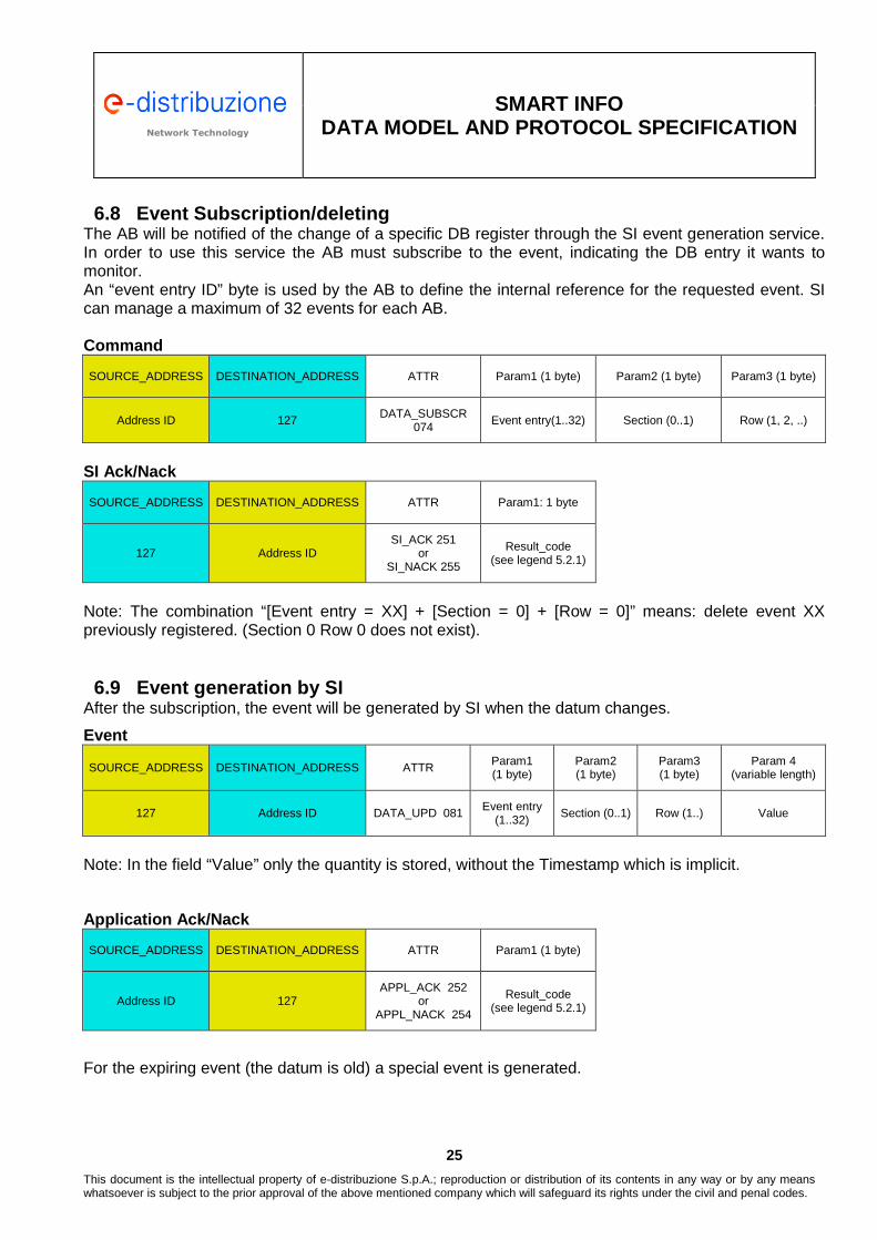
6.8 Event Subscription/deleting The AB will be notified of the change of a specific DB register through the SI event generation service. In order to use this service the AB must subscribe to the event, indicating the DB entry it wants to monitor. An “event entry ID” byte is used by the AB to define the internal reference for the requested event. SI can manage a maximum of 32 events for each AB. Command
SOURCE_ADDRESS DESTINATION_ADDRESS ATTR Param1 (1 byte) Param2 (1 byte) Param3 (1 byte)
Address ID 127 DATA_SUBSCR 074
Event entry(1..32) Section (0..1) Row (1, 2, ..)
SI Ack/Nack
SOURCE_ADDRESS DESTINATION_ADDRESS ATTR Param1: 1 byte
127 Address ID SI_ACK 251
or SI_NACK 255
Result_code (see legend 5.2.1)
Note: The combination “[Event entry = XX] + [Section = 0] + [Row = 0]” means: delete event XX previously registered. (Section 0 Row 0 does not exist). 6.9 Event generation by SI
After the subscription, the event will be generated by SI when the datum changes.
Event
SOURCE_ADDRESS DESTINATION_ADDRESS ATTR Param1 (1 byte)
Param2 (1 byte)
Param3 (1 byte)
Param 4 (variable length)
127 Address ID DATA_UPD 081 Event entry (1..32)
Section (0..1) Row (1..) Value
Note: In the field “Value” only the quantity is stored, without the Timestamp which is implicit.
Application Ack/Nack
SOURCE_ADDRESS DESTINATION_ADDRESS ATTR Param1 (1 byte)
Address ID 127 APPL_ACK 252
or APPL_NACK 254
Result_code (see legend 5.2.1)
For the expiring event (the datum is old) a special event is generated.

Network Technology Network Technology
SMART INFO
DATA MODEL AND PROTOCOL SPECIFICATION
26
This document is the intellectual property of e-distribuzione S.p.A.; reproduction or distribution of its contents in any way or by any means whatsoever is subject to the prior approval of the above mentioned company which will safeguard its rights under the civil and penal codes.
Event
SOURCE_ADDRESS DESTINATION_ADDRESS ATTR Param1 (1 byte)
Param2 (1 byte)
Param3 (1 byte)
127 Address ID DATA_EXP 083 Event entry (1..32)
Section (0..1) Row (1..)
Application Ack/Nack
SOURCE_ADDRESS DESTINATION_ADDRESS ATTR Param1 (1 byte)
Address ID 127 APPL_ACK 252
or APPL_NACK 254
Result_code (see legend 5.2.1)
6.10 AB asks for load profile log
With this request the AB requests the transmission of the load profile log buffer.
Log Type: 4 for active positive Energy. Log Type: 7 for active negative Energy from primary meter. Log Type: 11 for active negative Energy from secondary meter. Request
SOURCE_ADDRESS DESTINATION_ADDRESS ATTR Param: 1 byte
Address ID 127 START_LOG 078 Log type
Response
SOURCE_ADDRESS
DESTINATION_ADDRESS ATTR
Param1 (5 bytes) yy/mm/dd/hh/mm
Param2 (2 bytes)
Param3 (1 byte)
Param4 (1 byte) Param 5 (4 bytes)
127 Address ID Log delivery Resp 077
Time of first sample conveyed in the log
Total num of
samples Ti Log Type
Absolute value of first sample
conveyed in the log
If log is not available a SI_NACK (log not available) will be generated.
Log Type is encoded as below:
Code Description
[1,3] Deprecated
4
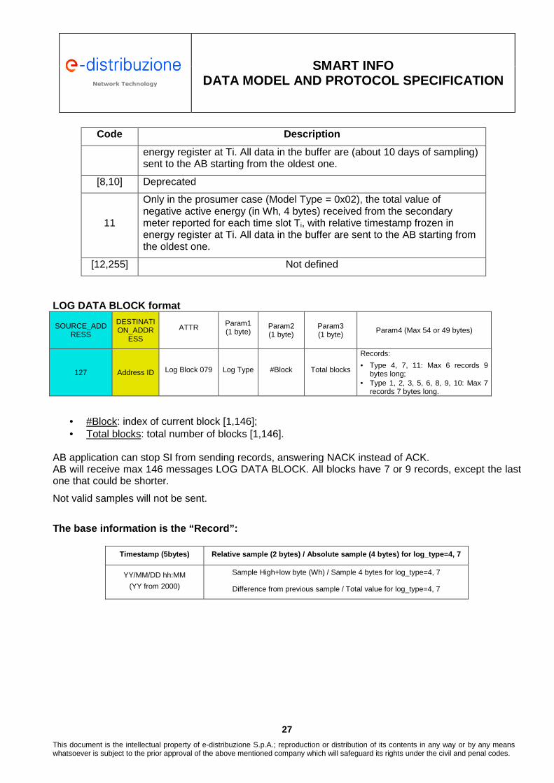
Total value of positive active energy (in Wh, 4 bytes) reported for each time slot Ti, with relative timestamp frozen in the energy register at Ti. All data in the buffer are (about 10 days of sampling) sent to the AB starting from the oldest one.
[5,6] Deprecated
7 Total value of negative active energy (in Wh, 4 bytes) received by primary meter reported for each time slot Ti, with relative timestamp frozen in
Network Technology Network Technology
SMART INFO
DATA MODEL AND PROTOCOL SPECIFICATION
27
This document is the intellectual property of e-distribuzione S.p.A.; reproduction or distribution of its contents in any way or by any means whatsoever is subject to the prior approval of the above mentioned company which will safeguard its rights under the civil and penal codes.
Code Description
energy register at Ti. All data in the buffer are (about 10 days of sampling) sent to the AB starting from the oldest one.
[8,10] Deprecated
11
Only in the prosumer case (Model Type = 0x02), the total value of negative active energy (in Wh, 4 bytes) received from the secondary meter reported for each time slot Ti, with relative timestamp frozen in energy register at Ti. All data in the buffer are sent to the AB starting from the oldest one.
[12,255] Not defined
LOG DATA BLOCK format
SOURCE_ADDRESS
DESTINATION_ADDR
ESS
ATTR Param1 (1 byte)
Param2 (1 byte)
Param3 (1 byte) Param4 (Max 54 or 49 bytes)
127 Address ID Log Block 079 Log Type #Block Total blocks
Records:
• Type 4, 7, 11: Max 6 records 9 bytes long;
• Type 1, 2, 3, 5, 6, 8, 9, 10: Max 7 records 7 bytes long.
• #Block: index of current block [1,146]; • Total blocks: total number of blocks [1,146].
AB application can stop SI from sending records, answering NACK instead of ACK. AB will receive max 146 messages LOG DATA BLOCK. All blocks have 7 or 9 records, except the last one that could be shorter.
Not valid samples will not be sent.
The base information is the “Record”:
Timestamp (5bytes) Relative sample (2 bytes) / Abso lute sample (4 bytes) for log_type=4, 7
YY/MM/DD hh:MM
(YY from 2000) Sample High+low byte (Wh) / Sample 4 bytes for log_type=4, 7
Difference from previous sample / Total value for log_type=4, 7
Network Technology Network Technology
SMART INFO
DATA MODEL AND PROTOCOL SPECIFICATION
28
This document is the intellectual property of e-distribuzione S.p.A.; reproduction or distribution of its contents in any way or by any means whatsoever is subject to the prior approval of the above mentioned company which will safeguard its rights under the civil and penal codes.
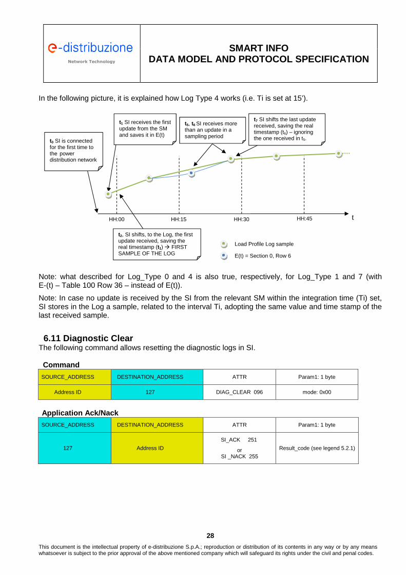
In the following picture, it is explained how Log Type 4 works (i.e. Ti is set at 15’).
Note: what described for Log_Type 0 and 4 is also true, respectively, for Log_Type 1 and 7 (with E-(t) – Table 100 Row 36 – instead of E(t)).
Note: In case no update is received by the SI from the relevant SM within the integration time (Ti) set, SI stores in the Log a sample, related to the interval Ti, adopting the same value and time stamp of the last received sample.
6.11 Diagnostic Clear
The following command allows resetting the diagnostic logs in SI. Command
SOURCE_ADDRESS DESTINATION_ADDRESS ATTR Param1: 1 byte
Address ID 127 DIAG_CLEAR 096 mode: 0x00
Application Ack/Nack
SOURCE_ADDRESS DESTINATION_ADDRESS ATTR Param1: 1 byte
127 Address ID
SI_ACK 251
or SI _NACK 255
Result_code (see legend 5.2.1)
t HH:00 HH:15 HH:30 HH:45
t0 SI is connected for the first time to the power distribution network
t1 SI receives the first update from the SM and saves it in E(t)
t2, SI shifts, to the Log, the first update received, saving the real timestamp (t1) � FIRST SAMPLE OF THE LOG
t7 SI shifts the last update received, saving the real timestamp (t6) – ignoring the one received in t5.
Load Profile Log sample
E(t) = Section 0, Row 6
t5, t6 SI receives more than an update in a sampling period

Network Technology Network Technology
SMART INFO
DATA MODEL AND PROTOCOL SPECIFICATION
29
This document is the intellectual property of e-distribuzione S.p.A.; reproduction or distribution of its contents in any way or by any means whatsoever is subject to the prior approval of the above mentioned company which will safeguard its rights under the civil and penal codes.
6.12 Publication of device configuration informatio n Through this command the AB application can retrieve information form SI relevant to NID, FW version and PLC modem type.
Request
SOURCE_ADDRESS DESTINATION_ADDRESS ATTR Param: 1 byte
Address ID 127 SI_INFO_REQ 090 Info_set_code
Response
SOURCE_ADDRESS DESTINATION_ADDRESS ATTR Parm1 (1 byte)
Param2 (8 bytes)
Param3 (6 bytes)
Param4 (8 bytes)
Param5 (2 bytes)
Param6 (1 byte)
127 Address ID SI_INFO_RES 091 Info_set_code
SI release (ASCII format)
NID SI
Modem SW
stack release
Modem firmware release
SI type
Notes: • “Info set code” shall be set equal to 0x00.
• “SI release” is in ASCII format, it defines the program name (6 bytes) + major_release (1 byte) + minor_release (1 byte).
• “NID SI” is the SI identification code printed on its label. It is showed as an HEX string.
• “Modem sw stack release”: it defines the modem software stack program name (6 bytes) + major_release (1 byte) + minor_release (1 byte).
• “Modem firmware release” it defines the firmware release of the Modem.
• “SI type” defines the type of Modem.
6.13 Application LED Status Command With this command the AB application can set the status of the yellow/green “Application LED” resident on the SI. Command:
SOURCE_ADDRESS DESTINATION_ADDRESS ATTR Param1: 1 byte
Address ID 127 SET_AB_LED 076 Led_status
Application Ack/Nack:
SOURCE_ADDRESS DESTINATION_ADDRESS ATTR Param1: 1 byte
127 Address ID
SI_ACK 251
or
SI_NACK 255
Result_code (see legend in section 4.5.2)

Network Technology Network Technology
SMART INFO
DATA MODEL AND PROTOCOL SPECIFICATION
30
This document is the intellectual property of e-distribuzione S.p.A.; reproduction or distribution of its contents in any way or by any means whatsoever is subject to the prior approval of the above mentioned company which will safeguard its rights under the civil and penal codes.
7 Firmware Update SI firmware3 consists of a binary file with “.bin” extension. This firmware can be updated through the Xmodem protocol, implementing the procedure described in this section. If the procedure fails, it is always possible to restart the firmware upload procedure from the beginning. The update can be executed by using one of the SI USB ports with the settings detailed in section 5 (i.e 57600,n,8,1). In order to start the firmware upload it is necessary to send the following nine (9) characters ASCII string (Trailer):
"jJjJjJjJ0" Please note that the trailer string deletes the Firmware version currently resident on SI. It is necessary to wait at least 500 ms or a NACK repeated by SI every 3 seconds when the communication is absent (meaning that SI is ready for the upload process), and then after it is possible to download blocks of 128 bytes extracted from the binary file. The firmware upload command is: Firmware Upload Request
SOH Firmware Block Number
Firmware Block Number Check
Firmware block Checksum
0x01
Binary number, starts at 0x01 increments by 1, and wraps at 0xFF to 0x00 (not to 0x01)
Binary number calculated as
0xFF- Firmware Block Number
128 bytes extracted from binary file
The sum of the data bytes only
(Discard any carry).
Note: If the last block to be sent is less than 128 bytes, this shall be padded with bytes set equal to 0x1A. Checksum shall be calculated considering the padding bytes. In case the last block is filled with 128 valid bytes, it is necessary to send another block filled with 128 padding bytes only. Firmware Upload Response Ack
ACK
0x06
Firmware Upload Response Nack
NACK
0x15
Note: SI FW UPLOAD NACK response requires the host application to re-send the firmware block.
3 Use only official firmware released by e-distribuzione.

Network Technology Network Technology
SMART INFO
DATA MODEL AND PROTOCOL SPECIFICATION
31
This document is the intellectual property of e-distribuzione S.p.A.; reproduction or distribution of its contents in any way or by any means whatsoever is subject to the prior approval of the above mentioned company which will safeguard its rights under the civil and penal codes.
At the end of the firmware upload sequence, the communication shall be terminated with an “end of transmission” character: End of Transmission
eot
0x04
End of Transmission Response (ACK)
ACK
0x06
After the last acknowledgment the new version of SI firmware boots and starts. 7.1 Data flow example including error recovery
For the sake of clarity, the following diagram offers an example of the data flow entailed during firmware upload procedure.

Network Technology Network Technology
SMART INFO
DATA MODEL AND PROTOCOL SPECIFICATION
32
This document is the intellectual property of e-distribuzione S.p.A.; reproduction or distribution of its contents in any way or by any means whatsoever is subject to the prior approval of the above mentioned company which will safeguard its rights under the civil and penal codes.
8 Data Model 8.1 Data format
Data format Ecode C ANSI
equivalence Description
Ebyte 1 Unsigned char 1 byte coded as required by the application Eshort 2 Unsigned char 1 byte coded as integer (0-255)
Eword 3 Short unsigned int
2 bytes coded as required by the application (most significant bit first)
EPower 4 Short unsigned int
2 bytes used for a short unsigned integer, most significant byte first, used for Power Resolution: 1 W (VAr, for reactive)4
EEnergy 5 Long unsigned int 4 bytes used for a long unsigned integer, most significant byte first, used for Energy Resolution: 1 Wh (VArh, for reactive)
Edate 6 Structure
Structure 3 bytes long: 41 Day (Values 1..31) 42 Month (Values 1..12) 43 Year (Values 00-99, 00 = 2000)
Etime 7 Structure
Structure 3 bytes long: 21 hours 2 minutes 23 seconds
EtimeA 8 Structure
Structure 4 bytes long: 01 day 02 hours 03 minutes 04 seconds
ESEnergy 9 Long int 4 bytes used for a long signed integer, most significant byte first, used for Energy Prepaid Resolution: 1 Wh
EBArray 1XX Bytes array String of XX bytes max, null terminated, XX not defined EBArrayB 2XX Bytes array Array of XX bytes, not defined EWArray 3XX Word array Array of XX words, most significant byte first ETimeB 10 Structure ETime + EDate in row (6 bytes)
EPcredit 11 Structure
Structure: • Long signed integer: amount of Wh purchased • Unsigned integer: code of purchase operation
Used for prepaid function
EPowMul 4X Short unsigned int
2 bytes used for a short unsigned integer, most significant byte first. The value is intended as “Unit * 10^X”. E.g., if X = 1, the unit of measure is (*10); if 2 is (*100). It is used for power Resolution: 10 W. Power in decaWatt is used for some polyphase quantities.
EPowDiv 5X Short unsigned int
2 bytes used for a short unsigned integer, most significant byte first.
4 If Model Type is set as 0x01 or 0x03, the Power Resolution is 1 decaWatt only for fields contained in Table 100
Network Technology Network Technology
SMART INFO
DATA MODEL AND PROTOCOL SPECIFICATION
33
This document is the intellectual property of e-distribuzione S.p.A.; reproduction or distribution of its contents in any way or by any means whatsoever is subject to the prior approval of the above mentioned company which will safeguard its rights under the civil and penal codes.
Data format Ecode C ANSI
equivalence Description
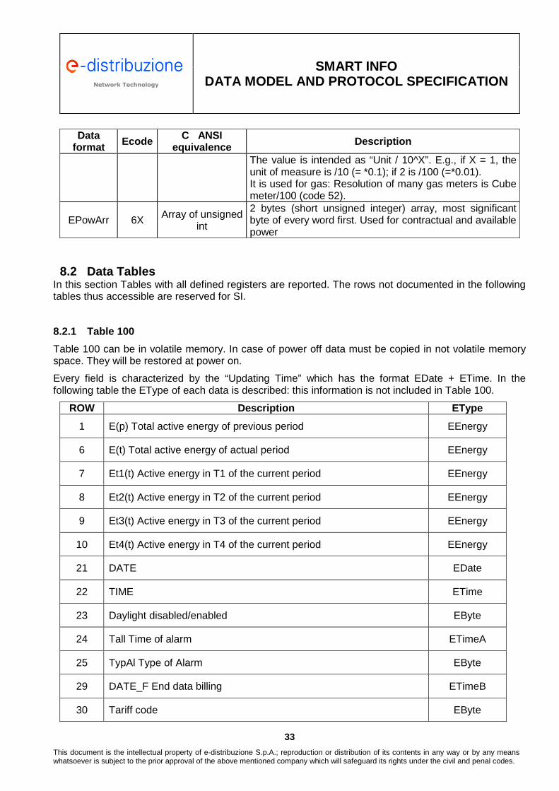
The value is intended as “Unit / 10^X”. E.g., if X = 1, the unit of measure is /10 (= *0.1); if 2 is /100 (=*0.01). It is used for gas: Resolution of many gas meters is Cube meter/100 (code 52).
EPowArr 6X Array of unsigned int
2 bytes (short unsigned integer) array, most significant byte of every word first. Used for contractual and available power
8.2 Data Tables
In this section Tables with all defined registers are reported. The rows not documented in the following tables thus accessible are reserved for SI.
8.2.1 Table 100
Table 100 can be in volatile memory. In case of power off data must be copied in not volatile memory space. They will be restored at power on.
Every field is characterized by the “Updating Time” which has the format EDate + ETime. In the following table the EType of each data is described: this information is not included in Table 100.
ROW Description EType
1 E(p) Total active energy of previous period EEnergy
6 E(t) Total active energy of actual period EEnergy
7 Et1(t) Active energy in T1 of the current period EEnergy
8 Et2(t) Active energy in T2 of the current period EEnergy
9 Et3(t) Active energy in T3 of the current period EEnergy
10 Et4(t) Active energy in T4 of the current period EEnergy
21 DATE EDate
22 TIME ETime
23 Daylight disabled/enabled EByte
24 Tall Time of alarm ETimeA
25 TypAl Type of Alarm EByte
29 DATE_F End data billing ETimeB
30 Tariff code EByte

Network Technology Network Technology
SMART INFO
DATA MODEL AND PROTOCOL SPECIFICATION
34
This document is the intellectual property of e-distribuzione S.p.A.; reproduction or distribution of its contents in any way or by any means whatsoever is subject to the prior approval of the above mentioned company which will safeguard its rights under the civil and penal codes.
ROW Description EType
36 E-(t) Total negative active energy of actual period EEnergy
50 Ra(t) Total value of positive reactive energy in the current period EEnergy
101 Total daily active energy current date ESEnergy
105 Instant Power (Average in Time Tx, 1 second) - PTx EPower
106 Button Status Ebyte
108 Production SM Negative Total active energy of actual period EEnergy
120 Diagnostic notification queue I EBArrayB(36)
121 Diagnostic notification queue II EBArrayB(36)
• “DATE_F End data billing” refers to the scheduled data for the total active energy acquisition from
SMCC
8.2.2 Table 101
Table 101 is in a not-volatile memory. Static data or long time updating data.
Every field is characterized by the “Updating Time” which has the format Edate + Etime. In the following table the EType of each data is described: this information is not included in Table 101.
ROW Description EType
1 Contractual power EPower
2 Available Power EPower
18 Model Type EWord
22 POD (Point of Delivery) EBArray(15)
24 TI Integration time for Load Profile in minutes EByte
33 Power Unit Mode EByte
45 NID SI EBArray(6)
• “Model Type” defines SI function codes:
Device Meter type ID Utility primary Meter (default for SI) 0x0000 Utility Production Meter 0x0001 Utility primary Meter + Utility Production Meter 0x0002 Private primary Meter 0x100

Network Technology Network Technology
SMART INFO
DATA MODEL AND PROTOCOL SPECIFICATION
35
This document is the intellectual property of e-distribuzione S.p.A.; reproduction or distribution of its contents in any way or by any means whatsoever is subject to the prior approval of the above mentioned company which will safeguard its rights under the civil and penal codes.
Device Meter type ID Private Production Meter 0x101 Private Secondary meter 0x102 Generic Meter 0x110
• “Power Unit Mode”, defines the unit of measurement adopted by SM for EPower data in Table 100:
Device Power Unit Mode Value
Watt (Primary meter) – Watt (Production Meter) 0x00 Decawatt (Primary meter) – Watt (Production Meter) 0x01 Watt (Primary meter) – Decawatt (Production Meter) 0x02 Decawatt (Primary meter) – Decawatt (Production Meter) 0x03
• “NID SI” is the SI identification code printed on its label. It should be showed as an HEX string.

Network Technology Network Technology
SMART INFO
DATA MODEL AND PROTOCOL SPECIFICATION
36
This document is the intellectual property of e-distribuzione S.p.A.; reproduction or distribution of its contents in any way or by any means whatsoever is subject to the prior approval of the above mentioned company which will safeguard its rights under the civil and penal codes.
9 Automatic diagnostic function 9.1 Introduction
SI have an automatic diagnostic function, realized through two tasks:
1. PERIODIC CHECK ENGINE: information are periodically gathered and updated 2. REAL TIME DIAGNOSTIC: notifications are generated as a result of events
Diagnostic Function fills-in two dedicated log registers in Table 100. Diagnostic events are recorded by SI during its operation. These registers support a rapid solution of possible problems of different nature (wrong configurations, lack of communication, etc.) that can arise during its operation and in the interaction with the SM. Diagnostic events, when necessary, are marked with time-stamp providing the precise time instant when the events has been recorded. The time-stamp is created based on the information available from RTC, supplied by a dedicated back-up battery. Hence the RTC has therefore to be considered as a reliable source. Diagnostic registers are stored in a permanent memory (flash memory), each time their value changes, and are restored in RAM in Table 100 when SI is powered-on. This simplifies diagnostic information fetch operations. Diagnostic information registers data can be retrieved by the host application. Increasing details level relevant to diagnostic functionality and fault/error codes are provided in next section of this document. 9.2 Periodic Check Engine
SI has a, background running, periodic check engine that continuously verifies the general operation of SI. In the notifications description section (ref. 9.7) the notification check type is detailed (periodic or real-time). Periodic check engine clears the diagnostic information when it detects that the SM connected to SI has been changed. Hence, the uploading of a new script into SI results in clearing recorded statistic data. 9.3 Real-Time Diagnostic
SI responds in real-time to events, considering faults, operating and communication Notification description section errors. In the notifications description section (ref. 9.7) the notification check type is detailed (periodic or real-time).

Network Technology Network Technology
SMART INFO
DATA MODEL AND PROTOCOL SPECIFICATION
37
This document is the intellectual property of e-distribuzione S.p.A.; reproduction or distribution of its contents in any way or by any means whatsoever is subject to the prior approval of the above mentioned company which will safeguard its rights under the civil and penal codes.
9.4 Diagnostic registers and relevant management
As provided in section 8.2.1, the following diagnostic registers are present in Table 100:
ROW 120 Diagnostic notification queue I EBArrayB(36) (36 bytes)
ROW 121 Diagnostic notification queue II EBArrayB(36) (36 bytes)
[DSL(T1] These two registers are operated jointly: diagnostic events are recorded starting from queue I and then after queue II is used. When the overall queue limit is reached, the first notification recorded in queue I, is removed to give room to the new notification that will be inserted in queue II. This is similar to a queue FIFO management.
[DSL(T2] Each notification has this structure:
(byte 1) (byte 2) (byte 3 – 6)
notification_type notification_code extra_info:
posix time stamp or extra[4]
A possible C-language declaration for the notification structure is as follows: typedef struct{ //type of notification unsigned char notification_type; //data linked to the notification unsigned char notification_code; union{ unsigned long posix; //timestamp - format posix (unix epoch) unsigned char extra[4]; //used to provide more effective information when the
time stamp is not meaningful }extra_info;
} struct_notification; // � 6 bytes[DSL(T3]
Hence, it is possible to store up to 12 notifications. 'notification_code' byte is used to further detail the notification typology (eg: TYPE_HOST_LINK|CHECKSUM_ERROR) and is described in the following sections of this document relevant to the description of notification.

Network Technology Network Technology
SMART INFO
DATA MODEL AND PROTOCOL SPECIFICATION
38
This document is the intellectual property of e-distribuzione S.p.A.; reproduction or distribution of its contents in any way or by any means whatsoever is subject to the prior approval of the above mentioned company which will safeguard its rights under the civil and penal codes.
In the following the term “same-type notifications” is used to refer to notifications characterized by the same value of the couple (notification_type, notification_code). 9.5 Events management
Notifications can be inserted into Log registers in the following modalities: 1. STRAIGHTFORWARD INSERT: a new element is added into registers, possibly removing the
oldest element. This modality is used when there is no same-type notification in the registers.
2. MODE_OVERWRITE: Log management overwrites the “same-type notification”, if already present in the registers, and updates the time-stamp. As a result of this operation, the events are not stored in the registers ordered by their time-stamp; nevertheless, the time stamp, associated with each notification, allows to reconstruct the chronological order.
3. MODE_SKIP_IF_PRESENT: Log management does not overwrite the “same-type notification”, if already present, and does not update the time-stamp.
4. MODE_UPDATE: Log management updates the notification_code field of the notification that has RESUMED and updates the time-stamp. This modality extends the behavior of the MODE_OVERWRITE, updating the notification_code to the state RESUMED.
Modalities 2 and 3 limit the risks associated with the notification queue free space depletion. 9.6 Notification Types
The notification types (differentiated by the value notification_type) are:
Types Notification _type value Examples
Informative TYPE_INFO 1 Application start, diagnostic cleared
Internal operating error TYPE_ERROR 2 Bad or missing configurations
Warning and degradation signalling TYPE_WARNING 3 Events
No operation TYPE_FATAL 4 Fatal errors
Power Line Communication Error TYPE_PW_LINK 5
SM tables with wrong dimensions, wrong limits, data update not received, not plausible data, etc.)
Host Communciation Error
TYPE_HOST_LINK 6
Errors in the communication with the Host, script upload errors, bad command syntax, command parameters error, etc.
The notifications structure allows for the introduction of new typologies, when necessary.

Network Technology Network Technology
SMART INFO
DATA MODEL AND PROTOCOL SPECIFICATION
39
This document is the intellectual property of e-distribuzione S.p.A.; reproduction or distribution of its contents in any way or by any means whatsoever is subject to the prior approval of the above mentioned company which will safeguard its rights under the civil and penal codes.
9.7 Notification list The following table summarizes the notifications typologies providing the management modality.
Notification Type Notification Code Tipo Check Extra Info Insert Modality
TYPE_INFO (1) NOTIFICATION_BOOT (1) Real-Time Time Stamp MODE_OVERWRITE
TYPE_INFO (1) NOTIFICATION_DIAGNOSTIC_CLEARED (2) Real-Time Time Stamp MODE_OVERWRITE
TYPE_INFO (1) NOTIFICATION_DIAGNOSTIC_AUTOCLEARED (3) Real-Time Time Stamp MODE_OVERWRITE
TYPE_ERROR (2) NOTIFICATION_CE_NOT_ASSIGNED (1) PERIODIC CHECK ENGINE Time Stamp MODE_SKIP_IF_PRESENT
TYPE_ERROR (2) NOTIFICATION_CE_NOT_ASSIGNED_RESUMED (2) PERIODIC CHECK ENGINE Time Stamp MODE_UPDATE
TYPE_ERROR (2) NOTIFICATION_AVAILABLE_POWER_NOT_ASSIGNED (3) PERIODIC CHECK ENGINE Time Stamp MODE_SKIP_IF_PRESENT
TYPE_ERROR (2) NOTIFICATION_AVAILABLE_POWER_NOT_ASSIGNED_RESUMED (4) PERIODIC CHECK ENGINE Time Stamp MODE_UPDATE
TYPE_ERROR (2) NOTIFICATION_TAB_CODE_PRIMARY_NO_MAPPING (5) PERIODIC CHECK ENGINE extra[]=000000XX MODE_SKIP_IF_PRESENT
TYPE_ERROR (2) NOTIFICATION_TAB_CODE_PRIMARY_NO_MAPPING_RESUMED (6) PERIODIC CHECK ENGINE Time Stamp MODE_UPDATE
TYPE_ERROR (2) NOTIFICATION_TAB_CODE_SECONDARY_NO_MAPPING (7) PERIODIC CHECK ENGINE extra[]=000000XX MODE_SKIP_IF_PRESENT
TYPE_ERROR (2) NOTIFICATION_TAB_CODE_SECONDARY_NO_MAPPING_RESUMED (8) PERIODIC CHECK ENGINE Time Stamp MODE_UPDATE
TYPE_ERROR (2) NOTIFICATION_TAB_CODE_PRODUCTION_NO_MAPPING (9) PERIODIC CHECK ENGINE extra[]=000000XX MODE_SKIP_IF_PRESENT
TYPE_ERROR (2) NOTIFICATION_TAB_CODE_PRODUCTION_NO_MAPPING_RESUMED (10) PERIODIC CHECK ENGINE Time Stamp MODE_UPDATE
TYPE_ERROR (2) NOTIFICATION_CE_PRIMARY_TABLE_NOT_ASSIGNED (11) PERIODIC CHECK ENGINE Time Stamp MODE_SKIP_IF_PRESENT
TYPE_ERROR (2) NOTIFICATION_CE_PRIMARY_TABLE_NOT_ASSIGNED_RESUMED (12) PERIODIC CHECK ENGINE Time Stamp MODE_UPDATE
TYPE_WARNING (3) NOTIFICATION_BATTERY_LOW (1) PERIODIC CHECK ENGINE Time Stamp MODE_SKIP_IF_PRESENT
TYPE_WARNING (3) NOTIFICATION_BATTERY_LOW_RESUMED (2) PERIODIC CHECK ENGINE Time Stamp MODE_UPDATE
TYPE_WARNING (3) NOTIFICATION_NO_PERIODIC_DATA_FROM_PRIMARY_CE (3) PERIODIC CHECK ENGINE Time Stamp MODE_SKIP_IF_PRESENT
TYPE_WARNING (3) NOTIFICATION_NO_PERIODIC_DATA_FROM_PRIMARY_CE_RESUMED (4) PERIODIC CHECK ENGINE Time Stamp MODE_UPDATE
TYPE_WARNING (3) NOTIFICATION_NO_PERIODIC_DATA_FROM_SECONDARY_CE (5) PERIODIC CHECK ENGINE Time Stamp MODE_SKIP_IF_PRESENT
TYPE_WARNING (3) NOTIFICATION_NO_PERIODIC_DATA_FROM_SECONDARY_CE_RESUMED (6) PERIODIC CHECK ENGINE Time Stamp MODE_UPDATE
TYPE_WARNING (3) NOTIFICATION_UNRESPONSIVE_PRIMARY_TABLE (7) Real-Time Time Stamp MODE_SKIP_IF_PRESENT
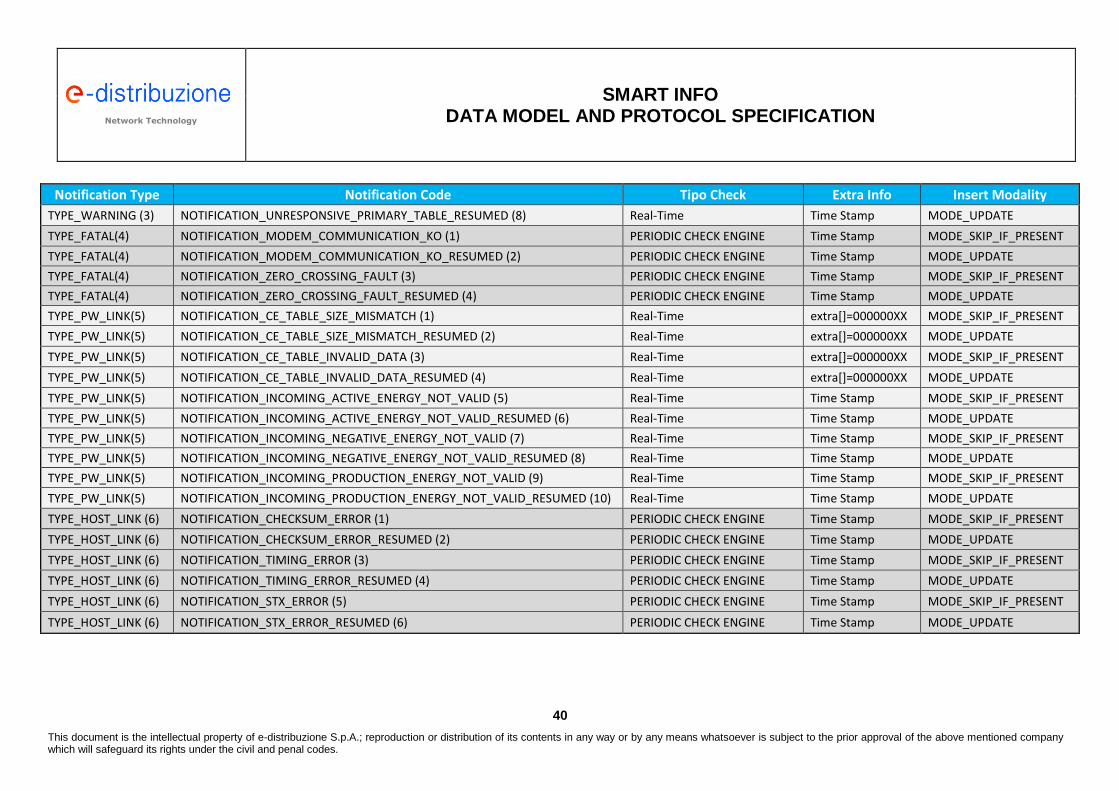
Network Technology Network Technology
SMART INFO
DATA MODEL AND PROTOCOL SPECIFICATION
40
This document is the intellectual property of e-distribuzione S.p.A.; reproduction or distribution of its contents in any way or by any means whatsoever is subject to the prior approval of the above mentioned company which will safeguard its rights under the civil and penal codes.
Notification Type Notification Code Tipo Check Extra Info Insert Modality
TYPE_WARNING (3) NOTIFICATION_UNRESPONSIVE_PRIMARY_TABLE_RESUMED (8) Real-Time Time Stamp MODE_UPDATE
TYPE_FATAL(4) NOTIFICATION_MODEM_COMMUNICATION_KO (1) PERIODIC CHECK ENGINE Time Stamp MODE_SKIP_IF_PRESENT
TYPE_FATAL(4) NOTIFICATION_MODEM_COMMUNICATION_KO_RESUMED (2) PERIODIC CHECK ENGINE Time Stamp MODE_UPDATE
TYPE_FATAL(4) NOTIFICATION_ZERO_CROSSING_FAULT (3) PERIODIC CHECK ENGINE Time Stamp MODE_SKIP_IF_PRESENT
TYPE_FATAL(4) NOTIFICATION_ZERO_CROSSING_FAULT_RESUMED (4) PERIODIC CHECK ENGINE Time Stamp MODE_UPDATE
TYPE_PW_LINK(5) NOTIFICATION_CE_TABLE_SIZE_MISMATCH (1) Real-Time extra[]=000000XX MODE_SKIP_IF_PRESENT
TYPE_PW_LINK(5) NOTIFICATION_CE_TABLE_SIZE_MISMATCH_RESUMED (2) Real-Time extra[]=000000XX MODE_UPDATE
TYPE_PW_LINK(5) NOTIFICATION_CE_TABLE_INVALID_DATA (3) Real-Time extra[]=000000XX MODE_SKIP_IF_PRESENT
TYPE_PW_LINK(5) NOTIFICATION_CE_TABLE_INVALID_DATA_RESUMED (4) Real-Time extra[]=000000XX MODE_UPDATE
TYPE_PW_LINK(5) NOTIFICATION_INCOMING_ACTIVE_ENERGY_NOT_VALID (5) Real-Time Time Stamp MODE_SKIP_IF_PRESENT
TYPE_PW_LINK(5) NOTIFICATION_INCOMING_ACTIVE_ENERGY_NOT_VALID_RESUMED (6) Real-Time Time Stamp MODE_UPDATE
TYPE_PW_LINK(5) NOTIFICATION_INCOMING_NEGATIVE_ENERGY_NOT_VALID (7) Real-Time Time Stamp MODE_SKIP_IF_PRESENT
TYPE_PW_LINK(5) NOTIFICATION_INCOMING_NEGATIVE_ENERGY_NOT_VALID_RESUMED (8) Real-Time Time Stamp MODE_UPDATE
TYPE_PW_LINK(5) NOTIFICATION_INCOMING_PRODUCTION_ENERGY_NOT_VALID (9) Real-Time Time Stamp MODE_SKIP_IF_PRESENT
TYPE_PW_LINK(5) NOTIFICATION_INCOMING_PRODUCTION_ENERGY_NOT_VALID_RESUMED (10) Real-Time Time Stamp MODE_UPDATE
TYPE_HOST_LINK (6) NOTIFICATION_CHECKSUM_ERROR (1) PERIODIC CHECK ENGINE Time Stamp MODE_SKIP_IF_PRESENT
TYPE_HOST_LINK (6) NOTIFICATION_CHECKSUM_ERROR_RESUMED (2) PERIODIC CHECK ENGINE Time Stamp MODE_UPDATE
TYPE_HOST_LINK (6) NOTIFICATION_TIMING_ERROR (3) PERIODIC CHECK ENGINE Time Stamp MODE_SKIP_IF_PRESENT
TYPE_HOST_LINK (6) NOTIFICATION_TIMING_ERROR_RESUMED (4) PERIODIC CHECK ENGINE Time Stamp MODE_UPDATE
TYPE_HOST_LINK (6) NOTIFICATION_STX_ERROR (5) PERIODIC CHECK ENGINE Time Stamp MODE_SKIP_IF_PRESENT
TYPE_HOST_LINK (6) NOTIFICATION_STX_ERROR_RESUMED (6) PERIODIC CHECK ENGINE Time Stamp MODE_UPDATE

Network Technology Network Technology
SMART INFO
DATA MODEL AND PROTOCOL SPECIFICATION
41
This document is the intellectual property of e-distribuzione S.p.A.; reproduction or distribution of its contents in any way or by any means whatsoever is subject to the prior approval of the above mentioned company which will safeguard its rights under the civil and penal codes.
9.7.1 Notifications with only informative content
notification_type: TYPE_INFO (1) These are the possible value for the notification_code: NOTIFICATION_BOOT notification_code = 1
Description: This notification notifies the “application start” with relevant timestamp. This notification is useful to determine when the application started, and to assess if SI RTC was synchronized at the application start stage. This is also useful to diagnose unexpected reboot/crash of the application/device. Management Policy: Real-Time, MODE_OVERWRITE. One only NOTIFICATION_BOOT will always be present in the queue with the time stamp value equal to the last application start instant.
NOTIFICATION_DIAGNOSTIC_CLEARED notification_code = 2 Description: This notifies the diagnostic registers reset, as a result of the command DIAG_CLEAR (ref. 6.11). Management Policy: Real-Time, MODE_OVERWRITE. No more than one only NOTIFICATION_DIAGNOSTIC_CLEARED will always be present in the queue with the time stamp value equal to the diagnostic clear command execution instant.
NOTIFICATION_DIAGNOSTIC_AUTOCLEARED notification_code = 3 Description: This notifies the diagnostic registers reset, as a result of a change in the configuration relevant to the linked primary meter, and/or to the secondary meter if applicable. This event also implies the reset of all the statics, the Table 100 values and the logs (e.g. load profiles). Management Policy: Real-Time, MODE_OVERWRITE. No more than one only NOTIFICATION_DIAGNOSTIC_AUTOCLEARED will always be present in the queue with the time stamp value equal to the last auto clear execution instant.
9.7.2 Notifications relevant to errors preventing SI operation
notification_type: TYPE_ERROR (2) These are the possible value for the notification_code: NOTIFICATION_CE_NOT_ASSIGNED notification_code = 1 NOTIFICATION_CE_NOT_ASSIGNED_RESUMED notification_code = 2
Description: This notification notifies the lack of the address configuration relevant to the SM to be linked with SI. This prevents the possibility to retrieve data from the SM. Management Policy: PERIODIC CHECK ENGINE, MODE_SKIP_IF_PRESENT

Network Technology Network Technology
SMART INFO
DATA MODEL AND PROTOCOL SPECIFICATION
42
This document is the intellectual property of e-distribuzione S.p.A.; reproduction or distribution of its contents in any way or by any means whatsoever is subject to the prior approval of the above mentioned company which will safeguard its rights under the civil and penal codes.
No more than one only NOTIFICATION_CE_NOT_ASSIGNED will always be present in the queue. In case the problem is solved, the notification is UPDATED, moving to NOTIFICATION_CE_NOT_ASSIGNED_RESUMED state.
NOTIFICATION_AVAILABLE_POWER_NOT_ASSIGNED notification_code = 3 NOTIFICATION_AVAILABLE_POWER_NOT_ASSIGNED_RESUMED notification_code = 4
Description: This notification notifies the lack of the Available Power configuration (TAB101/Row2). This situation prevents a series of functionalities and verifications on the data exchanged with the SM.
Management Policy: PERIODIC CHECK ENGINE, MODE_SKIP_IF_PRESENT No more than one only NOTIFICATION_AVAILABLE_POWER_NOT_ASSIGNED will always be present in the queue. In case the problem is solved, the notification is UPDATED, moving to NOTIFICATION_AVAILABLE_POWER_NOT_ASSIGNED_RESUMED state. Note: during application start up (at device power-on), if the address of the SM to be link is configured, the application force a read of the “Available Power” configuration data from the SM. Hence, if this initial procedure succeeds, this configuration problem is automatically solved.
NOTIFICATION_TAB_CODE_PRIMARY_NO_MAPPING notification_code = 5 NOTIFICATION_TAB_CODE_PRIMARY_NO_MAPPING_RESUMED notification_code = 6
Description: Returns the error code XX due to an internal SI wrong configuration. Management Policy: PERIODIC CHECK ENGINE, MODE_SKIP_IF_PRESENT No more than one only NOTIFICATION_TAB_CODE_PRIMARY_NO_MAPPING will always be present in the queue. Since the information relevant to the time-stamp is not meaningful, this is replaced with the error code XX: extra[]=000000XX. In case the problem is solved, the notification is UPDATED, moving to NOTIFICATION_TAB_CODE_PRIMARY_NO_MAPPING_RESUMED state. The timestamp returns to be in this case meaningful, providing information about date and time of problem recovery (The problem has to be considered solved also in the case of error code reset).
NOTIFICATION_TAB_CODE_SECONDARY_NO_MAPPING notification_code = 7 NOTIFICATION_TAB_CODE_SECONDARY_NO_MAPPING_RESUMED notification_code = 8
Description: Returns the error code XX due to an internal SI wrong configuration.
Management Policy: PERIODIC CHECK ENGINE, MODE_SKIP_IF_PRESENT
Network Technology Network Technology
SMART INFO
DATA MODEL AND PROTOCOL SPECIFICATION
43
This document is the intellectual property of e-distribuzione S.p.A.; reproduction or distribution of its contents in any way or by any means whatsoever is subject to the prior approval of the above mentioned company which will safeguard its rights under the civil and penal codes.
No more than one only NOTIFICATION_TAB_CODE_SECONDARY_NO_MAPPING will always be present in the queue. Since the information relevant to the time-stamp is not meaningful, this is replaced with the error code XX: extra[]=000000XX. In case the problem is solved, the notification is UPDATED, moving to NOTIFICATION_TAB_CODE_SECONDARY_NO_MAPPING_RESUMED state. The timestamp returns to be in this case meaningful, providing information about date and time of problem recovery (The problem has to be considered solved also in the case of error code reset).
NOTIFICATION_TAB_CODE_PRODUCTION_NO_MAPPING notification_code = 9 NOTIFICATION_TAB_CODE_PRODUCTION_NO_MAPPING_RESUMED notification_code = 10
Description: Returns the error code XX due to an internal SI wrong configuration.
Management Policy: PERIODIC CHECK ENGINE, MODE_SKIP_IF_PRESENT No more than one only NOTIFICATION_TAB_CODE_PRODUCTION_NO_MAPPING will always be present in the queue. Since the information relevant to the time-stamp is not meaningful, this is replaced with the error code XX: extra[]=000000XX. In case the problem is solved, the notification is UPDATED, moving to NOTIFICATION_TAB_CODE_PRODUCTION_NO_MAPPING_RESUMED state. The timestamp returns to be in this case meaningful, providing information about date and time of problem recovery (The problem has to be considered solved also in the case of error code reset).
NOTIFICATION_CE_PRIMARY_TABLE_NOT_ASSIGNED notification_code = 11 NOTIFICATION_CE_PRIMARY_TABLE_NOT_ASSIGNED_RESUMED notification_code =12
Description: This notification notifies a configuration error relevant to primary Smart Mater description to be linked with SI. In case the address of the SM to be linked with SI has been configured, the diagnostic function further checks the configuration of the description of the SM to be linked. Without this configuration it is not possible to retrieve data from the SM. Management Policy: PERIODIC CHECK ENGINE, MODE_SKIP_IF_PRESENT No more than one only NOTIFICATION_CE_PRIMARY_TABLE_NOT_ASSIGNED will always be present in the queue. If the anomaly persists until the periodic check engine cycle, no further notification will be generated and the time-stamp relevant to first anomaly detection will remain in the notification. In case the problem is solved, the notification is UPDATED, moving to NOTIFICATION_CE_PRIMARY_TABLE_NOT_ASSIGNED_RESUMED state.

Network Technology Network Technology
SMART INFO
DATA MODEL AND PROTOCOL SPECIFICATION
44
This document is the intellectual property of e-distribuzione S.p.A.; reproduction or distribution of its contents in any way or by any means whatsoever is subject to the prior approval of the above mentioned company which will safeguard its rights under the civil and penal codes.
9.7.3 Notifications relevant to not fatal errors or operating conditions decay signaling
notification_type: TYPE_WARNING (3) These are the possible value for the notification_code: NOTIFICATION_BATTERY_LOW notification_code = 1 NOTIFICATION_BATTERY_LOW_RESUMED notification_code = 2
Description: This notifies that battery voltage value is below a threshold critical value, entailing a possible risk to lose the RTC back-up. This situation may result in the possibility of an application restart with a wrong time reference until a subsequent synchronization with the SM is performed.
Management Policy: PERIODIC CHECK ENGINE, MODE_SKIP_IF_PRESENT No more than one only NOTIFICATION_BATTERY_LOW will always be present in the queue. In case the problem is solved, the notification is UPDATED, moving to NOTIFICATION_BATTERY_LOW_RESUMED state. Note: possible subsequent problems, linked with the successive crossing of the critical threshold value will correspond to multiple events of this code present in the queue in the RESUMED state.
NOTIFICATION_NO_PERIODIC_DATA_FROM_PRIMARY_CE notification_code = 3 NOTIFICATION_NO_PERIODIC_DATA_FROM_PRIMARY_CE_RESUMED notification_code = 4
Description: This notifies the lack of updated information from the primary meter linked with SI for a time interval longer than 2 hours. Management Policy: PERIODIC CHECK ENGINE, MODE_SKIP_IF_PRESENT No more than one only NOTIFICATION_NO_PERIODIC_DATA_FROM_PRIMARY_CE will always be present in the queue. If the anomaly persists (for a subsequent period longer than 2 hours) no further notification will be generated and the time-stamp relevant to first anomaly detection will remain in the notification. By comparing the current time with the time stamp it will then be possible to identify the total communication inactivity period. In case the problem is solved, the notification is UPDATED, moving to NOTIFICATION_NO_PERIODIC_DATA_FROM_PRIMARY_CE_RESUMED state.
NOTIFICATION_NO_PERIODIC_DATA_FROM_SECONDARY_CE notification_code = 5 NOTIFICATION_NO_PERIODIC_DATA_FROM_SECONDARY_CE_RESUMED notification_code = 6
Description: This notifies the lack of updated information from the secondary meter linked with SI for a time interval longer than 2 hours.

Network Technology Network Technology
SMART INFO
DATA MODEL AND PROTOCOL SPECIFICATION
45
This document is the intellectual property of e-distribuzione S.p.A.; reproduction or distribution of its contents in any way or by any means whatsoever is subject to the prior approval of the above mentioned company which will safeguard its rights under the civil and penal codes.
Management Policy: PERIODIC CHECK ENGINE, MODE_SKIP_IF_PRESENT No more than one only NOTIFICATION_NO_PERIODIC_DATA_FROM_SECONDARY_CE will always be present in the queue. If the anomaly persists (for a subsequent period longer than 2 hours) no further notification will be generated and the time-stamp relevant to first anomaly detection will remain in the notification. By comparing the current time with the notification time stamp it will then be possible to identify the total communication inactivity period. In case the problem is solved, the notification is UPDATED, moving to NOTIFICATION_NO_PERIODIC_DATA_FROM_SECONDARY_CE_RESUMED state.
NOTIFICATION_UNRESPONSIVE_PRIMARY_TABLE notification_code = 7 NOTIFICATION_UNRESPONSIVE_PRIMARY_TABLE_RESUMED notification_code = 8
Description: This notifies that it has not been possible to get from the SM validly updated information from the primary meter linked with SI for a time interval longer than 1 hour. In this case the test on the validity of the received data is repeated at the beginning of the following day. Management Policy: REAL TIME, MODE_SKIP_IF_PRESENT No more than one only NOTIFICATION_UNRESPONSIVE_PRIMARY_TABLE notification will always be present in the queue. If the anomaly persists (for a subsequent period longer than 1 hour) no further notifications will be generated. If the anomaly persists (across consecutive days) no further notifications will be generated and the time-stamp relevant to first anomaly detection will remain in the notification. By comparing the current time with the notification time stamp it will then be possible to identify the total duration of the not validly update period. In case the problem is solved, the notification is UPDATED, moving to NOTIFICATION_UNRESPONSIVE_PRIMARY_TABLE_RESUMED state.
9.7.4 Notification relevant to faults preventing SI operation
notification_type: TYPE_FATAL(4) These are the possible value for the notification_code: NOTIFICATION_MODEM_COMMUNICATION_KO notification_code = 1 NOTIFICATION_MODEM_COMMUNICATION_KO_RESUMED notification_code = 2
Description: This notifies the impossibility to communicate with the integrated PLC modem trough the internal serial link between microprocessor and modem. It is therefore not possible to configure PLC MODEM. Hence, SI device will not be operating due to lack of communication with PLC modem. Management Policy: PERIODIC CHECK ENGINE, MODE_SKIP_IF_PRESENT

Network Technology Network Technology
SMART INFO
DATA MODEL AND PROTOCOL SPECIFICATION
46
This document is the intellectual property of e-distribuzione S.p.A.; reproduction or distribution of its contents in any way or by any means whatsoever is subject to the prior approval of the above mentioned company which will safeguard its rights under the civil and penal codes.
No more than one only NOTIFICATION_MODEM_COMMUNICATION_KO will always be present in the queue. In case the problem is solved, the notification is UPDATED, moving to NOTIFICATION_MODEM_COMMUNICATION_KO_RESUMED state.
NOTIFICATION_ZERO_CROSSING_FAULT notification_code = 3 NOTIFICATION_ZERO_CROSSING_FAULT_RESUMED notification_code = 4
Description: This notifies the lack of “zero crossing detection” functionality at the period check engine cycle. This shortage could be ascribed to a lack in the connection of the PLC modem to the power line or in a fault in the coupling circuit between the PLC modem and the power line (this diagnostic result is not meant to identify micro interruptions).
Management Policy: PERIODIC CHECK ENGINE, MODE_SKIP_IF_PRESENT No more than one only NOTIFICATION_ZERO_CROSSING_FAULT will always be present in the queue. In case the problem is solved, the notification is UPDATED, moving to NOTIFICATION_ZERO_CROSSING_FAULT_RESUMED state. The RESUMED state is achieved only if the operating conditions remain without this type of problem for at least 40 s.
9.7.5 Notifications relevant to issues on Power Line communication
notification_type: TYPE_PW_LINK(5) These are the possible value for the notification_code: NOTIFICATION_CE_TABLE_SIZE_MISMATCH notification_code = 1 NOTIFICATION_CE_TABLE_SIZE_MISMATCH_RESUMED notification_code = 2
Description: This notifies an error detected in the dimension of the payload carrying data from SM. This error roots in a wrong configuration of the Smart Meter onSM on the SI device. The whole table is discharged both for payload lengths longer and shorter than expected.
Management Policy: Real-Time, MODE_SKIP_IF_PRESENT No more than one only NOTIFICATION_CE_TABLE_SIZE_MISMATCH will always be present in the queue for each specific table that generated the error. Since the information relevant to the time-stamp is not meaningful, this is replaced with the error code XX: extra[]=000000XX. In case the problem is solved, the notification is UPDATED, moving to NOTIFICATION_CE_TABLE_SIZE_MISMATCH_RESUMED state. Note: The events queue can contain no more than one only notification instance for each error code relevant to SI configuration parameters.

Network Technology Network Technology
SMART INFO
DATA MODEL AND PROTOCOL SPECIFICATION
47
This document is the intellectual property of e-distribuzione S.p.A.; reproduction or distribution of its contents in any way or by any means whatsoever is subject to the prior approval of the above mentioned company which will safeguard its rights under the civil and penal codes.
Troubleshooting: If this error only seldom occurs, it has to be tolerated since this may be due to an occasional collision on the power line link. In this case when the normal operation is restored (as a consequence of a subsequent dataset received from the SM) the notification is UPDATED, moving to NOTIFICATION_CE_TABLE_SIZE_MISMATCH_RESUMED state. If this error is persistent then the problem has to be searched in a bad SI configuration.
NOTIFICATION_CE_TABLE_INVALID_DATA notification_code = 3 NOTIFICATION_CE_TABLE_INVALID_DATA_RESUMED notification_code = 4
Description: This notifies an error in the interpretation of payload contained in the data received from the SM. This notification corresponds to the case when payload has a correct length, but the values contained therewith are, at least partially, clearly wrong. The error can stem from:
17.1. An error in the SI configuration. Length corresponds, but data are not validly configured (most likely);
17.2. Collisions of frames on the power line communication link with consequent payload corruption (anomaly quite rare).
Data are considered not valid if: • Check on value of power: the power value received is greater than the double of the value
of the available power; • Check on date/time: the values etime/edate/eposix have incorrect syntax.
Management Policy: Real-Time, MODE_SKIP_IF_PRESENT No more than one only NOTIFICATION_CE_TABLE_INVALID_DATA will always be present in the queue for each specific table that generated the error. Since the information relevant to the time-stamp is not meaningful, this is replaced with the error code XX: extra[]=000000XX. In case the problem is solved, the notification is UPDATED, moving to NOTIFICATION_CE_TABLE_INVALID_DATA_RESUMED state updating the time stamp.
Troubleshooting. : If this error only seldom occurs it has to be tolerated, since this may be due to an occasional collision on a congested power line link: In this case when the normal operation is restored (as a consequence of a subsequent dataset received from the SM) the notification is UPDATED, moving to NOTIFICATION_CE_TABLE_INVALID_DATA_RESUMED state. If this error is persistent then the problem has to be searched in a bad SI configuration.
NOTIFICATION_INCOMING_ACTIVE_ENERGY_NOT_VALID notification_code = 5 NOTIFICATION_INCOMING_ACTIVE_ENERGY_NOT_VALID_RESUMED notification_code = 6 Description:

Network Technology Network Technology
SMART INFO
DATA MODEL AND PROTOCOL SPECIFICATION
48
This document is the intellectual property of e-distribuzione S.p.A.; reproduction or distribution of its contents in any way or by any means whatsoever is subject to the prior approval of the above mentioned company which will safeguard its rights under the civil and penal codes.
This notifies that the value of the “Total active energy of actual period” (Tab100/Row6) coming from the primary Meter is lower than the previously received value of the same register. The error cause has to be searched between: − CASE 1: payload corruption relevant to current data − CASE 2: payload corruption relevant to the previously received data with a value
excessively high, even if still monotonic increasing.
Management Policy: Real-Time, MODE_SKIP_IF_PRESENT No more than one only NOTIFICATION_INCOMING_ACTIVE_ENERGY_NOT_VALID will always be present in the queue. To restore the monotonic increasing series, avoiding the discharge of correct values, the restore is performed in these cases:
- The data received from SI is monotonic increasing with respect to the previously received sample (the monotonic behavior is restored)
- The data received from SI is not monotonic increasing, but diagnostic function has alerted on the queue to have discharged the previously received sample (it is assumed that this sample is valid and the previously received sample – even if monotonic increasing – was not valid) The notification is in this case UPDATE as NOTIFICATION_INCOMING_ACTIVE_ENERGY_NOT_VALID_RESUMED.
Troubleshooting: The persistence of these events over a long period has to be considered as clue of a congested PowerLine Communication network.
NOTIFICATION_INCOMING_NEGATIVE_ENERGY_NOT_VALID notification_code = 7 NOTIFICATION_INCOMING_NEGATIVE_ENERGY_NOT_VALID_RESUMED notification_code = 8
Description: This notification is similar to the previous but it is referred to “Total negative active energy of actual period” (Tab100/Row36).

Network Technology Network Technology
SMART INFO
DATA MODEL AND PROTOCOL SPECIFICATION
49
This document is the intellectual property of e-distribuzione S.p.A.; reproduction or distribution of its contents in any way or by any means whatsoever is subject to the prior approval of the above mentioned company which will safeguard its rights under the civil and penal codes.
Management Policy: Real-Time, MODE_SKIP_IF_PRESENT No more than one only NOTIFICATION_INCOMING_NEGATIVE_ENERGY_NOT_VALID will always be present in the queue.
NOTIFICATION_INCOMING_PRODUCTION_ENERGY_NOT_VALID notification_code = 9 NOTIFICATION_INCOMING_PRODUCTION_ENERGY_NOT_VALID_RESUMED notification_code = 10
Description: This notification is similar to the previous but it is referred to “Production SM Negative Total active energy of actual period” (Tab100/Row108). It is necessary to have configured a link with a secondary meter. Management Policy: Real-Time, MODE_SKIP_IF_PRESENT No more than one only NOTIFICATION_INCOMING_PRODUCTION_ENERGY_NOT_VALID will always be present in the queue.
9.7.6 Notification of issues on communication with the Host
notification_type: TYPE_HOST_LINK (6) These are the possible value for the notification_code: NOTIFICATION_CHECKSUM_ERROR notification_code = 1 NOTIFICATION_CHECKSUM_ERROR_RESUMED notification_code = 2
Description: The notification referes to a checksum calculation error as a consequence of a command received by SI on the Host protocol. This may be due to an error in a excessive payload length. Management Policy: PERIODIC CHECK ENGINE, MODE_SKIP_IF_PRESENT No more than one only NOTIFICATION_CHECKSUM_ERROR will always be present in the queue. In case the problem is solved, the notification is UPDATED, moving to NOTIFICATION_CHECKSUM_ERROR_RESUMED state. In case of a persistent error no further notification will be generated. Possible repetitive errors on the checksum calculation will be signalled by a series of events in the queue in RESUMED state.
NOTIFICATION_TIMING_ERROR notification_code = 3 NOTIFICATION_TIMING_ERROR_RESUMED notification_code = 4
Description: This notification refers to the error in the characters timing as a consequence of a command in the host protocol. This may also reflect an error in a payload length shorter than expected.
Management Policy: PERIODIC CHECK ENGINE, MODE_SKIP_IF_PRESENT

Network Technology Network Technology
SMART INFO
DATA MODEL AND PROTOCOL SPECIFICATION
50
This document is the intellectual property of e-distribuzione S.p.A.; reproduction or distribution of its contents in any way or by any means whatsoever is subject to the prior approval of the above mentioned company which will safeguard its rights under the civil and penal codes.
No more than one only NOTIFICATION_TIMING_ERROR will always be present in the queue. In case of a persistent error no further notification will be generated.
In case the problem is solved, the notification is UPDATED, moving to NOTIFICATION_TIMING_ERROR_RESUMED state. Possible repetitive errors will be signalled by a series of events in the queue in RESUMED state.
NOTIFICATION_STX_ERROR notification_code = 5 NOTIFICATION_STX_ERROR_RESUMED notification_code = 6
Description: The notifications refers to the detection of an error in the Start Character in a Host protocol command. This may reflect a baud-rate error a trunked message. Management Policy: PERIODIC CHECK ENGINE, MODE_SKIP_IF_PRESENT No more than one only NOTIFICATION_STX_ERROR will always be present in the queue. In case of a persistent error no further notification will be generated. In case the problem is solved, the notification is UPDATED, moving to NOTIFICATION_STX_ERROR_RESUMED state.