Embed Size (px)
Citation preview
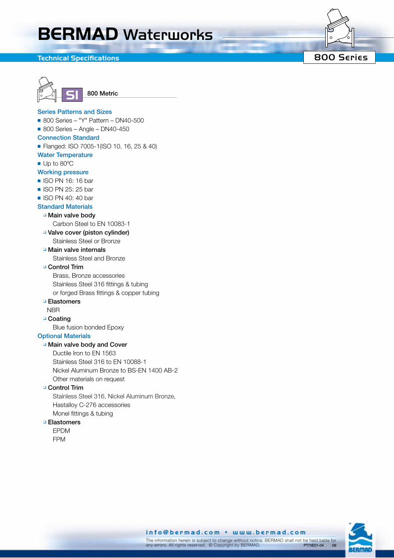
BERMAD Waterworks 800 SeriesTechnical Specifications
800 MetricSISeries Patterns and Sizes ■ 800 Series – "Y" Pattern – DN40-500■ 800 Series – Angle – DN40-450Connection Standard■ Flanged: ISO 7005-1(ISO 10, 16, 25 & 40) Water Temperature■ Up to 80ºCWorking pressure■ ISO PN 16: 16 bar■ ISO PN 25: 25 bar■ ISO PN 40: 40 barStandard Materials
q Main valve body Carbon Steel to EN 10083-1
q Valve cover (piston cylinder) Stainless Steel or Bronze
q Main valve internals Stainless Steel and Bronze
q Control Trim Brass, Bronze accessories Stainless Steel 316 fittings & tubing or forged Brass fittings & copper tubing
q Elastomers NBR
q Coating Blue fusion bonded EpoxyOptional Materials
q Main valve body and Cover Ductile Iron to EN 1563 Stainless Steel 316 to EN 10088-1 Nickel Aluminum Bronze to BS-EN 1400 AB-2 Other materials on request
q Control Trim Stainless Steel 316, Nickel Aluminum Bronze, Hastalloy C-276 accessories Monel fittings & tubing
q Elastomers EPDM FPM
i n f o @ b e r m a d . c o m • w w w . b e r m a d . c o mThe information herein is subject to change without notice. BERMAD shall not be held liable forany errors. All rights reserved. © Copyright by BERMAD. PT7XE01-04 09PT7XE01-04 09

BERMAD Waterworks800 SeriesDimensions & Weights
800 "Y" Pattern DN 40 50 65 80 100 150 200 250 300 350 400 450 500
W
L
H
h
P
ISO
PN
10;
16
L (mm) 205 210 222 250 320 415 500 605 725 733 990 1,000 1,100W (mm) 156 166 190 200 229 286 344 408 484 536 600 638 716h (mm) 78 83 95 100 115 143 172 204 242 268 300 319 358H (mm) 260 265 278 327 409 526 650 763 942 969 1,154 1,173 1,211P* (mm) N/A N/A N/A N/A N/A 135 135 142 154 154 191 191 191
Weight (Kg) 10.7 13 16 28 48 94 162 272 455 482 1,000 1,074 1,096
ISO
PN
25;
40
L (mm) 205 210 222 264 335 433 524 637 762 767 1,024 1,030 1,136W (mm) 156 166 190 210 254 318 382 446 522 590 650 714 778h (mm) 78 83 95 105 127 159 191 223 261 295 325 357 389H (mm) 260 265 278 332 422 542 666 783 961 996 1,179 1,208 1,241P* (mm) N/A N/A N/A N/A N/A 135 135 142 154 154 191 191 191
Weight (Kg) 11.8 15 18.4 32 56 106 190 307 505 549 1,070 1,095 1,129
800 Angle DN 40 50 65 80 100 150 200 250 300 350 400 450
W
H
h
LR
P
ISO
PN
10
; 16
L (mm) 124 124 149 152 190 225 265 320 396 400 450 450W (mm) 156 166 190 200 229 285 344 408 496 528 598 640R (mm) 78 83 95 100 115 143 172 204 248 264 299 320h (mm) 85 85 109 102 127 152 203 219 273 279 369 370H (mm) 252 252 271 308 390 476 619 717 911 915 1,144 1,144P* (mm) N/A N/A N/A N/A N/A 141 141 156 156 156 195 195
Weight (Kg) 10.7 13 16 26 46 90 153 259 433 459 950 1,020
ISO
PN
25;
40
L (mm) 124 124 149 159 200 234 277 336 415 419 467 467W (mm) 150 155 190 200 254 318 381 446 522 586 650 716R (mm) 78 85 95 105 127 159 191 223 261 293 325 358h (mm) 85 85 109 109 135 165 216 236 294 299 386 386H (mm) 252 264 271 315 398 491 632 733 930 935 1,160 1,160P* (mm) N/A N/A N/A N/A N/A 141 141 156 156 156 195 195
Weight (Kg) 11.8 15 18.4 30 54 101 179 292 481 523 1,017 1,051
Control Chamber Displacement Volume (liter)
800 MetricSI
800 MetricSI
*P – Height of optional auxiliary closing piston or shaft balancing assembly
DN 40 50 65 80 100 150 200 250 300 350 400 450 500 600-900800 0.04 0.04 0.04 0.12 0.3 1.1 2.3 4 8 8 18.7 18.7 18.7 N/A
i n f o @ b e r m a d . c o m • w w w . b e r m a d . c o mThe information herein is subject to change without notice. BERMAD shall not be held liable forany errors. All rights reserved. © Copyright by BERMAD. PT7XE01-07 09

BERMAD Waterworks 800 Series
0.05
0.1
1.0
10 100 1,000 10,000
0.5
50 500 5,000
50040 65
5080 100 150 200 250 300 350 450
400
500100 150 200 250 300 350 450 600 700
750800900
4006550
8040
0.1
1.0
10 100 1,000 10,000
0.5
50 500 5,000
0.05
Flow Charts
Pre
ssur
e Lo
ss -
bar
Pre
ssur
e Lo
ss -
bar
Flow Rate - m3/h (Water)
Flow Rate - m3/h (Water)
Y Pattern, Throttling Plug (V-Port)
800 MetricSI
Y Pattern, Flat Disc
DN600-900 valves are Globe pattern
i n f o @ b e r m a d . c o m • w w w . b e r m a d . c o mThe information herein is subject to change without notice. BERMAD shall not be held liable forany errors. All rights reserved. © Copyright by BERMAD. PT7XE01-04 09

i n f o @ b e r m a d . c o m • w w w . b e r m a d . c o mThe information herein is subject to change without notice. BERMAD shall not be held liable forany errors. All rights reserved. © Copyright by BERMAD.
800 Series
BERMAD WaterworksFlow Charts
PT7XE01-11 09
0.05
6550
80 100 150 200 250 300 350 450400
40
0.1
1.0
10 100 1,000 10,000
0.5
50 500 5,000
0.05
0.1
1.0
10 100 1,000 10,000
0.5
50 500 5,000
6550
250 300 350 450400
40 80 100 150 200
Angle Pattern, Throttling Plug (V-Port)
Angle Pattern, Flat Disc
Pre
ssur
e Lo
ss -
bar
Pre
ssur
e Lo
ss -
bar
Flow Rate - m3/h (Water)
Flow Rate - m3/h (Water)
800 MetricSI
BERMAD Waterworks 800 SeriesFlow Properties
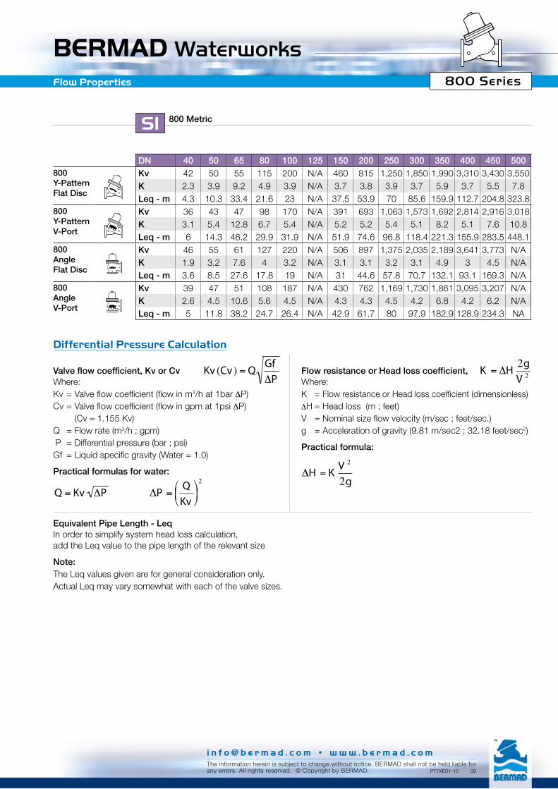
DN 40 50 65 80 100 125 150 200 250 300 350 400 450 500800Y-PatternFlat Disc
Kv 42 50 55 115 200 N/A 460 815 1,250 1,850 1,990 3,310 3,430 3,550K 2.3 3.9 9.2 4.9 3.9 N/A 3.7 3.8 3.9 3.7 5.9 3.7 5.5 7.8Leq - m 4.3 10.3 33.4 21.6 23 N/A 37.5 53.9 70 85.6 159.9 112.7 204.8 323.8
800Y-PatternV-Port
Kv 36 43 47 98 170 N/A 391 693 1,063 1,573 1,692 2,814 2,916 3,018K 3.1 5.4 12.8 6.7 5.4 N/A 5.2 5.2 5.4 5.1 8.2 5.1 7.6 10.8Leq - m 6 14.3 46.2 29.9 31.9 N/A 51.9 74.6 96.8 118.4 221.3 155.9 283.5 448.1
800Angle Flat Disc
Kv 46 55 61 127 220 N/A 506 897 1,375 2,035 2,189 3,641 3,773 N/AK 1.9 3.2 7.6 4 3.2 N/A 3.1 3.1 3.2 3.1 4.9 3 4.5 N/ALeq - m 3.6 8.5 27.6 17.8 19 N/A 31 44.6 57.8 70.7 132.1 93.1 169.3 N/A
800AngleV-Port
Kv 39 47 51 108 187 N/A 430 762 1,169 1,730 1,861 3,095 3,207 N/AK 2.6 4.5 10.6 5.6 4.5 N/A 4.3 4.3 4.5 4.2 6.8 4.2 6.2 N/ALeq - m 5 11.8 38.2 24.7 26.4 N/A 42.9 61.7 80 97.9 182.9 128.9 234.3 NA
800 MetricSI
Valve flow coefficient, Kv or CvWhere:Kv = Valve flow coefficient (flow in m3/h at 1bar ∆P)Cv = Valve flow coefficient (flow in gpm at 1psi ∆P) (Cv = 1.155 Kv)Q = Flow rate (m3/h ; gpm)∆P = Differential pressure (bar ; psi) Gf = Liquid specific gravity (Water = 1.0)
Practical formulas for water:
Flow resistance or Head loss coefficient, Where:K = Flow resistance or Head loss coefficient (dimensionless)∆H = Head loss (m ; feet)V = Nominal size flow velocity (m/sec ; feet/sec.)g = Acceleration of gravity (9.81 m/sec2 ; 32.18 feet/sec2)
Practical formula:
€
∆P =QKv
⎛ ⎝ ⎜
⎞ ⎠ ⎟
2
€
Q = Kv ∆P
€
∆H = KV 2
2g
€
Kv (Cv) = QGf∆P
Equivalent Pipe Length - LeqIn order to simplify system head loss calculation, add the Leq value to the pipe length of the relevant size
Note:The Leq values given are for general consideration only.Actual Leq may vary somewhat with each of the valve sizes.
€
K = ∆H2gV 2
Differential Pressure Calculation
i n f o @ b e r m a d . c o m • w w w . b e r m a d . c o mThe information herein is subject to change without notice. BERMAD shall not be held liable forany errors. All rights reserved. © Copyright by BERMAD. PT7XE01-15 09

BERMAD Waterworks 800 SeriesCavitation
Cavitation
The cavitation phenomenon has a significant affect on control valve and system performance.Cavitation may damage the valve and piping by the affects of erosion and vibration. Cavitation also generates noise and may limit and ultimately choke the flow. As the pressure differential across the valve increases, the static pressure of the flow passing through the throttling area of the valve (Vena Contracta) drops sharply. When the fluid’s static pressure reaches liquid vapor pressure, vapor cavities (bubbles) form and grow until they violently implode by the recovered pressure downstream to the valve seat. The implosion of these cavities generates high-pressure surges, micro jets and intensive heat, which erode valve components and downstream piping. In its final stage, cavitation flashes and chokes the flow.The above Cavitation Guides for Bermad 700 Series valves are based on the formula commonly used in the valve industry: σ = (P2-Pv) / (P1-P2)
Where:σ = Sigma, cavitation index, dimensionless P1 = Upstream pressure, absoluteP2 = Downstream pressure, absolutePv = Liquid vapor pressure, absolute (Water, 18ºC = 0.02 bar-a ; 65ºF = 0.3 psi-a)
Use these guides and your applications upstream and downstream pressures to determine whether their intersection lies in or out of the cavitation damage zone.Considerations to avoid cavitation damage:A) Reduce system pressure in stages designing each
pressure stage to be above cavitation conditions.B) Consider using other valve selection criteria a. Valve body and plug type b. Valve size c. Valve material
Notes:1. An alternate cavitation index formula introduced by
ISA is: σISA = (P1-Pv) / (P1-P2) which equals σ+1
2. The above charts should be considered only as a general guide.
3. For optimum system and control valve application please consult Bermad.
Cavitation Guide
8
7
6
5
4
3
2
1
00 2 4 6 8 10 12 14 16 18 20 22 24
8
7
6
5
4
3
2
1
00 2 4 6 8 10 12 14 16 18 20 22 24
Do
wns
trea
m p
ress
ure
- b
ar
Upstream pressure - bar
800
Cavitation Damage Zone
MetricSI
i n f o @ b e r m a d . c o m • w w w . b e r m a d . c o mThe information herein is subject to change without notice. BERMAD shall not be held liable forany errors. All rights reserved. © Copyright by BERMAD. PT7XE01-13 09

BERMAD Waterworks 800 SeriesTechnical Specifications
i n f o @ b e r m a d . c o m • w w w . b e r m a d . c o mThe information herein is subject to change without notice. BERMAD shall not be held liable forany errors. All rights reserved. © Copyright by BERMAD.
Series Patterns and Sizes ■ 800 Series – Y Pattern – 11/2"-20"■ 800 Series – Angle – 11/2"-18"Connection Standard■ Flanged: ANSI B16.5 (Cast steel) Water Temperature■ Up to 180ºFWorking pressure■ Class #150: 250 psi■ Class #300: 400 psi■ Class #400: 600 psiStandard Materials
q Main valve body Carbon Steel to ASTM A-216-WCB
q Valve cover (piston cylinder) Stainless Steel or Bronze
q Main valve internals Stainless Steel and Bronze
q Control Trim Brass, Bronze accessories Stainless Steel 316 fittings & tubing or forged Brass fittings & Copper tubing
q Elastomers NBR
q Coating Blue fusion bonded EpoxyOptional Materials
q Main valve body and Cover Ductile Iron to ASTM A-536 Stainless Steel 316 to ASTM A-743 CF8M Nickel Aluminum Bronze to ASTM B-148 C 95800 Other materials on request
q Control Trim Stainless Steel 316, Nickel Aluminum Bronze, Hastalloy C-276 accessories Monel fittings & tubing
q Elastomers EPDM FPM
800 EnglishUS
PT7XE01-05 09

BERMAD Waterworks800 SeriesDimensions & Weights
"Y" Pattern inch 11/2” 2” 21/2” 3” 4” 6” 8” 10” 12” 14” 16” 18” 20”
W
L
H
h
P
AN
SI 1
50
L 8.1 8.3 8.7 9.8 12.6 16.3 19.7 23.8 28.5 28.9 39 39.4 43.3W 6.1 6.5 7.5 7.9 9.0 11.3 13.5 16.1 19.1 21.1 23.6 25.1 28.2h 3.1 3.3 3.7 3.9 4.5 5.6 6.8 8 9.5 10.6 11.8 12.6 14.1H 10.2 10.4 10.9 12.9 16.1 20.7 25.6 30 37.1 38.1 45.4 46.2 47.7P* N/A N/A N/A N/A N/A 5.3 5.3 5.6 6.1 6.1 7.5 7.5 7.5
Weight (lb) 24 29 35 62 106 207 356 598 1,001 1,060 2,200 2,363 2,411
AN
SI 3
00; 4
00
L 8.1 8.3 8.7 10.4 13.2 17 20.6 25.1 30 30.2 40.3 40.6 44.7W 6.1 6.5 7.5 8.3 10.0 12.5 15.0 17.6 20.6 23.2 25.6 28.1 30.6h 3.1 3.3 3.7 4.1 5 6.3 7.5 8.8 10.3 11.6 12.8 14.1 15.3H 10.2 10.4 10.9 13.1 16.6 21.3 26.2 30.8 37.8 39.2 46.4 47.6 48.9P* N/A N/A N/A N/A N/A 5.3 5.3 5.6 6.1 6.1 7.5 7.5 7.5
Weight (lb) 26 33 40 70 123 233 418 675 1,111 1,208 2,354 2,409 2,484
Angle Pattern inch 11/2” 2” 21/2” 3” 4” 6” 8” 10” 12” 14” 16” 18”
W
H
h
LR
P
AN
SI 1
50
L 4.9 4.9 5.9 6 7.5 8.9 10.4 12.6 15.6 15.7 17.7 17.7W 6.1 6.5 7.5 7.9 9.0 11.2 13.5 16.1 19.5 20.8 23.5 25.2R 3.1 3.3 3.7 3.9 4.5 5.6 6.8 8.0 9.8 10.4 11.8 12.6h 3.3 3.3 4.3 4.0 5.0 6.0 8.0 8.6 10.7 11 14.5 14.6H 9.9 9.9 10.7 12.1 15.4 18.7 24.4 28.2 35.9 36 45 45P* N/A N/A N/A N/A N/A 5.6 5.6 6.1 6.1 6.1 7.7 7.7
Weight (lb) 24 29 35 57 101 198 337 570 953 1,010 2,090 2,244
AN
SI 3
00; 4
00
L 4.9 4.9 5.9 6.3 7.9 9.2 10.9 13.2 16.3 16.5 18.4 18.4W 5.9 6.1 7.5 7.9 10.0 12.5 15.0 17.6 20.6 23.1 25.6 28.2R 3.1 3.3 3.7 4.1 5 6.3 7.5 8.8 10.3 11.5 12.8 14.1h 3.3 3.3 4.3 4.3 5.3 6.5 8.5 9.3 11.6 11.8 15.2 15.2H 9.9 10.4 10.7 12.4 15.7 19.3 24.9 28.9 36.6 36.8 45.7 45.7P* N/A N/A N/A N/A N/A 5.6 5.6 6.1 6.1 6.1 7.7 7.7
Weight (lb) 26 33 40 66 119 222 394 642 1,058 1,151 2,237 2,312
Control Chamber Displacement Volume (gallon)
Sizes 11/2”-21/2” 3” 4” 6” 8” 10” 12”-14” 16”-20” 24”-36”800 Series 0.01 0.03 0.08 0.29 0.61 1.06 2.12 4.95 -
800 EnglishUS
800 EnglishUS
*P – Height of optional auxiliary closing piston or shaft balancing assembly
i n f o @ b e r m a d . c o m • w w w . b e r m a d . c o mThe information herein is subject to change without notice. BERMAD shall not be held liable forany errors. All rights reserved. © Copyright by BERMAD. PT7XE01-10 09

BERMAD Waterworks 800 Series
1
10
15
5
10 100 1,000 10,000 100,00050 500 5,000 50,000
3” 4” 6” 8” 18”12”
11/2”2”
21/2”14”16”
20”10”
1
10
15
5
10 100 1,000 10,000 100,00050 500 5,000 50,000
10”
24”
3” 4” 6” 8” 18”12”
11/2”2”
21/2”14”16”
20”28”30”32”36”
Flow Charts
800 EnglishUS
Y Pattern, Throttling Plug (V-Port)
Y Pattern, Flat Disc
Pre
ssur
e Lo
ss -
psi
Pre
ssur
e Lo
ss -
psi
Flow Rate - gpm (Water)
Flow Rate - gpm (Water)
DN600-900 valves are Globe pattern
i n f o @ b e r m a d . c o m • w w w . b e r m a d . c o mThe information herein is subject to change without notice. BERMAD shall not be held liable forany errors. All rights reserved. © Copyright by BERMAD.

i n f o @ b e r m a d . c o m • w w w . b e r m a d . c o mThe information herein is subject to change without notice. BERMAD shall not be held liable forany errors. All rights reserved. © Copyright by BERMAD.
800 Series
PT7XE01-12 09
BERMAD Waterworks
1
10
15
5
10 100 1,000 10,000 100,00050 500 5,000 50,000
12”3” 4” 6” 8” 18”11/2”
2”21/2”
14”16”10”
1
10
15
5
10 100 1,000 10,000 100,00050 500 5,000 50,000
3” 4” 6” 8” 18”12”
11/2”2”
21/2”14”16”10”
Flow Charts
800 EnglishUS
Angle Pattern, Flat Disc
Pre
ssur
e Lo
ss -
psi
Pre
ssur
e Lo
ss -
psi
Flow Rate - gpm (Water)
Flow Rate - gpm (Water)
Angle Pattern, Throttling Plug (V-Port)

BERMAD Waterworks 800 SeriesFlow Properties
inch 1.5" 2" 2.5" 3" 4" 6" 8" 10" 12" 14" 16" 18" 20"Y-PatternFlat Disc
Cv 49 58 64 133 230 530 940 1,440 2,140 2,300 3,820 3,960 4,100K 2.3 3.9 9.2 4.9 3.9 3.7 3.8 3.9 3.7 5.9 3.7 5.5 7.8Leq-feet 14.2 33.8 109.5 70.8 75.6 123.0 176.9 229.5 280.8 524.5 369.6 671.9 1,062.3
Y-PatternV-Port
Cv 41 49 54 113 200 450 800 1,230 1,820 1,950 3,250 3,370 3,490K 3.1 5.4 12.8 6.7 5.4 5.2 5.2 5.4 5.1 8.2 5.1 7.6 10.8Leq-feet 19.7 46.8 151.6 97.9 104.6 170.2 244.8 317.6 388.6 725.9 511.6 930.0 1,470.3
Angle PatternFlat Disc
Cv 53 64 70 146 250 580 1,040 1,590 2,350 2,530 4,210 4,360 NAK 1.9 3.2 7.6 4.0 3.2 3.1 3.1 3.2 3.1 4.9 3.0 4.5 NALeq-feet 11.7 28.0 90.5 58.5 62.5 101.6 146.2 189.7 232.0 433.4 305.5 555.3 NA
Angle PatternV-Port
Cv 45 54 59 124 220 500 880 1,350 2,000 2,150 3,580 3,710 NAK 2.6 4.5 10.6 5.6 4.5 4.3 4.3 4.5 4.2 6.8 4.2 6.2 NALeq-feet 16.3 38.7 125.3 80.9 86.5 140.7 202.4 262.5 321.2 599.9 422.8 768.6 NA
800 EnglishUS
Valve flow coefficient, Kv or CvWhere:Kv = Valve flow coefficient (flow in m3/h at 1bar ∆P)Cv = Valve flow coefficient (flow in gpm at 1psi ∆P) (Cv = 1.155 Kv)Q = Flow rate (m3/h ; gpm)∆P = Differential pressure (bar ; psi) Gf = Liquid specific gravity (Water = 1.0)
Practical formulas for water:
Flow resistance or Head loss coefficient, Where:K = Flow resistance or Head loss coefficient (dimensionless)∆H = Head loss (m ; feet)V = Nominal size flow velocity (m/sec ; feet/sec.)g = Acceleration of gravity (9.81 m/sec2 ; 32.18 feet/sec2)
Practical formula:
€
∆P =QKv
⎛ ⎝ ⎜
⎞ ⎠ ⎟
2
€
Q = Kv ∆P
€
∆H = KV 2
2g
€
Kv (Cv) = QGf∆P
Equivalent Pipe Length - LeqIn order to simplify system head loss calculation, add the Leq value to the pipe length of the relevant size
Note:The Leq values given are for general consideration only.Actual Leq may vary somewhat with each of the valve sizes.
€
K = ∆H2gV 2
Differential Pressure Calculation
i n f o @ b e r m a d . c o m • w w w . b e r m a d . c o mThe information herein is subject to change without notice. BERMAD shall not be held liable forany errors. All rights reserved. © Copyright by BERMAD. PT7XE01-16 09

BERMAD Waterworks 800 SeriesCavitation
Cavitation
The cavitation phenomenon has a significant affect on control valve and system performance.Cavitation may damage the valve and piping by the affects of erosion and vibration. Cavitation also generates noise and may limit and ultimately choke the flow. As the pressure differential across the valve increases, the static pressure of the flow passing through the throttling area of the valve (Vena Contracta) drops sharply. When the fluid’s static pressure reaches liquid vapor pressure, vapor cavities (bubbles) form and grow until they violently implode by the recovered pressure downstream to the valve seat. The implosion of these cavities generates high-pressure surges, micro jets and intensive heat, which erode valve components and downstream piping. In its final stage, cavitation flashes and chokes the flow.The above Cavitation Guide for Bermad 700 Series valves are based on the formula commonly used in the valve industry: σ = (P2-Pv) / (P1-P2)
Where:σ = Sigma, cavitation index, dimensionless P1 = Upstream pressure, absoluteP2 = Downstream pressure, absolutePv = Liquid vapor pressure, absolute (Water, 18ºC = 0.02 bar-a ; 65ºF = 0.3 psi-a)
Use these guide and your applications upstream and downstream pressures to determine whether their intersection lies in or out of the cavitation damage zone.Considerations to avoid cavitation damage:A) Reduce system pressure in stages designing each
pressure stage to be above cavitation conditions.B) Consider using other valve selection criteria a. Valve body and plug type b. Valve size c. Valve material
Notes:1. An alternate cavitation index formula introduced by
ISA is: σISA = (P1-Pv) / (P1-P2) which equals σ+1
2. The above charts should be considered only as a general guide.
3. For optimum system and control valve application please consult Bermad.
120
100
80
60
40
30
20
10
0
110
90
70
50
0 30 60 90 120 150 180 210 240 270 300 330 360
Cavitation Guide
Do
wns
trea
m p
ress
ure
- p
si
Upstream pressure - psi
Flat Disc
V-Port Plug
Cavitation Damage Zone
EnglishUS
i n f o @ b e r m a d . c o m • w w w . b e r m a d . c o mThe information herein is subject to change without notice. BERMAD shall not be held liable forany errors. All rights reserved. © Copyright by BERMAD. PT7XE01-14 09
i n f o @ b e r m a d . c o m • w w w . b e r m a d . c o mThe information herein is subject to change without notice. BERMAD shall not be held liable forany errors. All rights reserved. © Copyright by BERMAD.
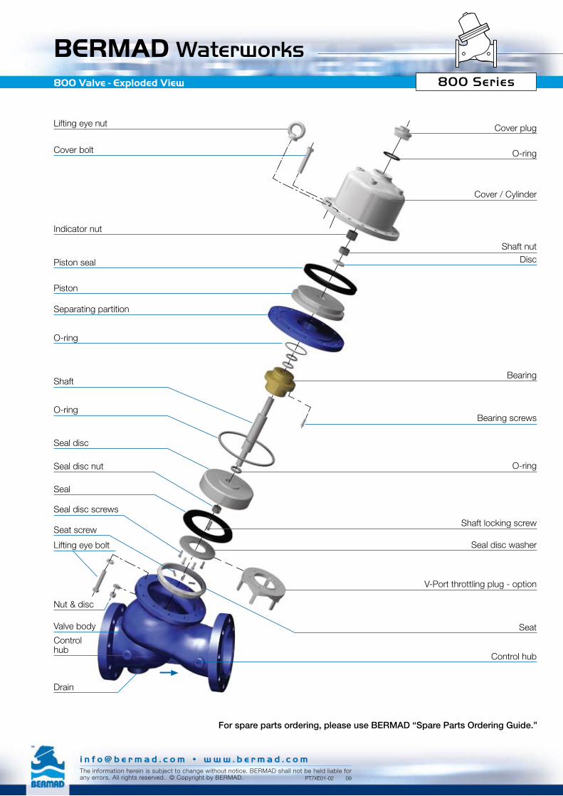
BERMAD Waterworks800 Valve - Exploded View 800 Series
PT7XE01-02 09
Cover plug
O-ring
Cover / Cylinder
Shaft nutDisc
Bearing
Bearing screws
O-ring
Shaft locking screw
Seal disc washer
V-Port throttling plug - option
Seat
Control hub
Lifting eye nut
Cover bolt
Indicator nut
Piston seal
Piston
Separating partition
O-ring
Shaft
O-ring
Seal disc
Seal disc nut
Seal
Seal disc screws
Seat screw
Lifting eye bolt
Nut & disc
Valve body
Control hub
Drain
For spare parts ordering, please use BERMAD “Spare Parts Ordering Guide.”
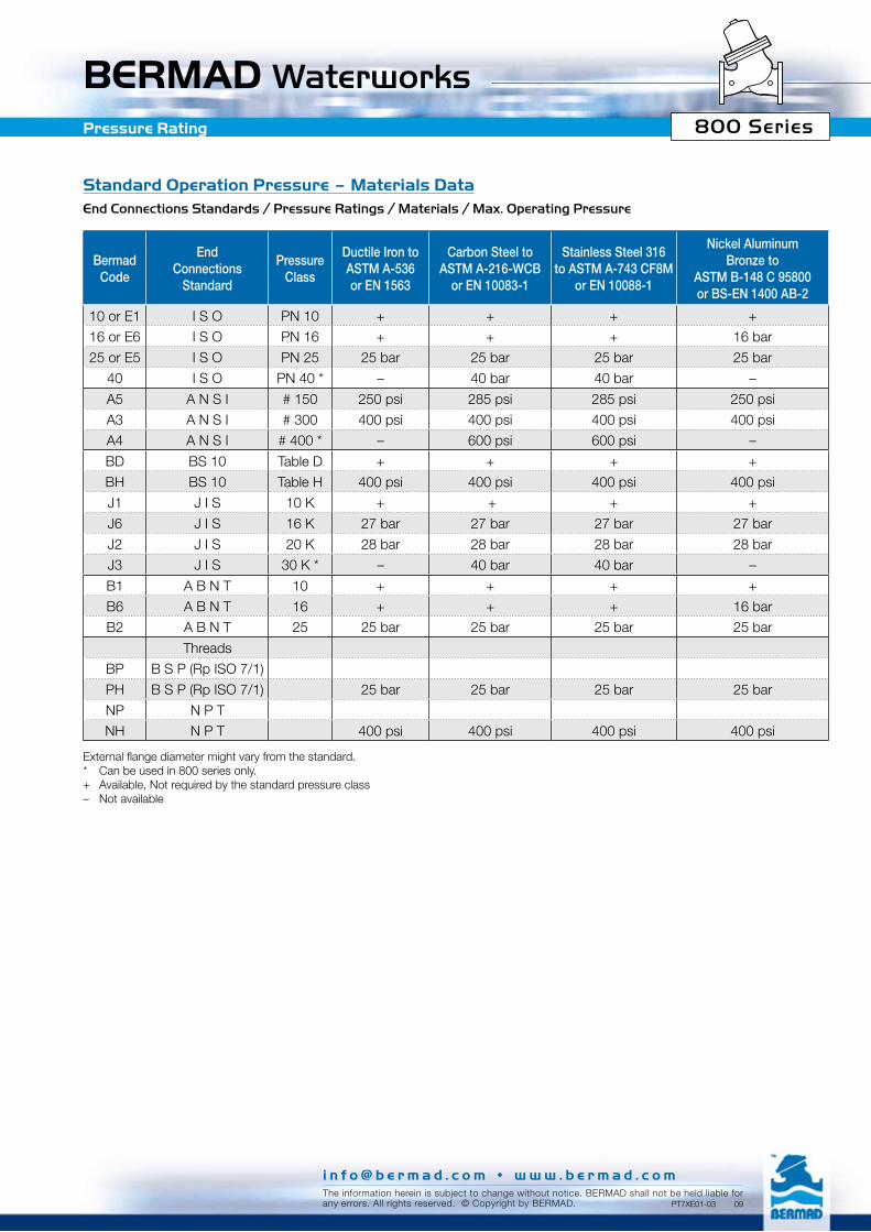
BERMAD Waterworks 800 SeriesPressure Rating
Standard Operation Pressure – Materials DataEnd Connections Standards / Pressure Ratings / Materials / Max. Operating Pressure
BermadCode
End Connections
Standard
Pressure Class
Ductile Iron to ASTM A-536 or EN 1563
Carbon Steel to ASTM A-216-WCB
or EN 10083-1
Stainless Steel 316 to ASTM A-743 CF8M
or EN 10088-1
Nickel Aluminum Bronze to
ASTM B-148 C 95800or BS-EN 1400 AB-2
10 or E1 I S O PN 10 + + + +
16 or E6 I S O PN 16 + + + 16 bar
25 or E5 I S O PN 25 25 bar 25 bar 25 bar 25 bar
40 I S O PN 40 * – 40 bar 40 bar –
A5 A N S I # 150 250 psi 285 psi 285 psi 250 psi
A3 A N S I # 300 400 psi 400 psi 400 psi 400 psi
A4 A N S I # 400 * – 600 psi 600 psi –
BD BS 10 Table D + + + +
BH BS 10 Table H 400 psi 400 psi 400 psi 400 psi
J1 J I S 10 K + + + +
J6 J I S 16 K 27 bar 27 bar 27 bar 27 bar
J2 J I S 20 K 28 bar 28 bar 28 bar 28 bar
J3 J I S 30 K * – 40 bar 40 bar –
B1 A B N T 10 + + + +
B6 A B N T 16 + + + 16 bar
B2 A B N T 25 25 bar 25 bar 25 bar 25 bar
Threads
BP B S P (Rp ISO 7/1)
PH B S P (Rp ISO 7/1) 25 bar 25 bar 25 bar 25 bar
NP N P T
NH N P T 400 psi 400 psi 400 psi 400 psi
External flange diameter might vary from the standard.* Can be used in 800 series only.+ Available, Not required by the standard pressure class– Not available
i n f o @ b e r m a d . c o m • w w w . b e r m a d . c o mThe information herein is subject to change without notice. BERMAD shall not be held liable forany errors. All rights reserved. © Copyright by BERMAD. PT7XE01-03 09
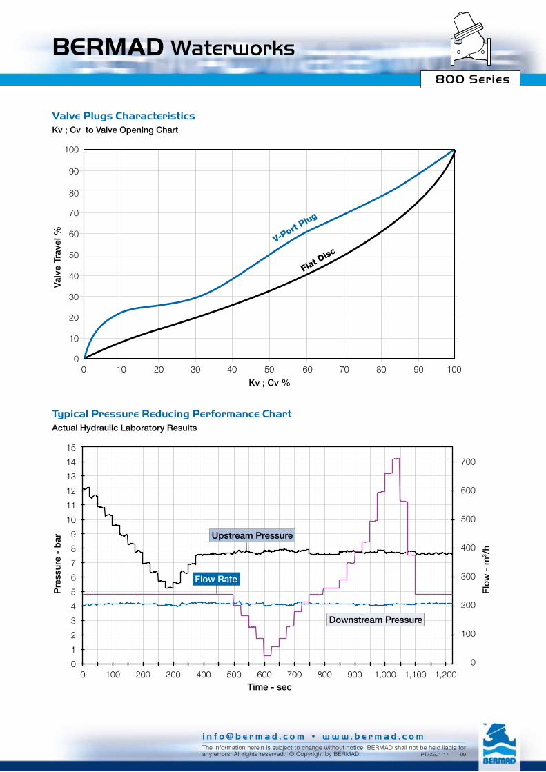
BERMAD Waterworks 800 Series
Valve Plugs CharacteristicsKv ; Cv to Valve Opening Chart
Typical Pressure Reducing Performance ChartActual Hydraulic Laboratory Results
0
10
20
30
40
50
60
70
80
90
100
0 10 20 30 40 50 60 70 80 90 100
15
14
13
12
11
10
9
8
7
6
5
4
3
2
1
00 100 200 300 400 500 600 700 800 900 1,000 1,100 1,200
700
600
500
400
300
200
100
0
V-Port Plug
Flat Disc
Valv
e Tr
avel
%
Kv ; Cv %
Pre
ssur
e -
bar
Flo
w -
m3 /
h
Upstream Pressure
Flow Rate
Downstream Pressure
Time - sec
i n f o @ b e r m a d . c o m • w w w . b e r m a d . c o mThe information herein is subject to change without notice. BERMAD shall not be held liable forany errors. All rights reserved. © Copyright by BERMAD. PT7XE01-17 09