Embed Size (px)
Citation preview

Shivkumar KalyanaramanRensselaer Polytechnic Institute
1
Multicast
Shivkumar Kalyanaraman
http://www.ecse.rpi.edu/Homepages/shivkumaAdapted in part from Srini Seshan’s (CMU) and Ion Stoica (UCB)

Shivkumar KalyanaramanRensselaer Polytechnic Institute
2
Why multicast ? Multicast apps ... Concepts: groups, scopes, trees Multicast addresses, LAN multicast Group management: IGMP Multicast routing and forwarding: MBONE, PIM Reliable Multicast Transport Protocols
Multicast Congestion Control Deployment issues, Source-Specific Multicast (SSM),
Application-level Multicast
Overview
Shivkumar KalyanaramanRensselaer Polytechnic Institute
3
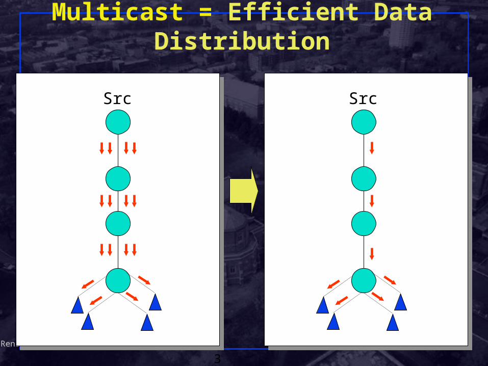
Multicast = Efficient Data Distribution
Src Src

Shivkumar KalyanaramanRensselaer Polytechnic Institute
4
Why Multicast ? Need for efficient one-to-many delivery of same data Applications:
News/sports/stock/weather updates Distance learning Configuration, routing updates, service location Pointcast-type “push” apps Teleconferencing (audio, video, shared whiteboard,
text editor) Distributed interactive gaming or simulations Email distribution lists Content distribution; Software distribution Web-cache updates Database replication

Shivkumar KalyanaramanRensselaer Polytechnic Institute
5
Why Not Broadcast or Unicast? Broadcast:
Send a copy to every machine on the net Simple, but inefficient All nodes must process packet even if they don’t care Wastes more CPU cycles of slower machines
(“broadcast radiation”) Network loops lead to “broadcast storms”
Replicated Unicast: Sender sends a copy to each receiver in turn Receivers need to register or sender must be pre-
configured Sender is focal point of all control traffic Reliability => per-receiver state, separate
sessions/processes at sender

Shivkumar KalyanaramanRensselaer Polytechnic Institute
6
Why IP multicast ? Application-layer relays:
A “relay” node or set of nodes does the replicated unicast function instead of the source
Multiple relays can handle “groups” of receivers and reduce number of packets per multicast => efficiency
Manager has to manually configure names of receivers in relays etc
App-level topology may be sub-optimalBut bandwidth is becoming cheaperBecoming more popular in content distribution
IP Multicast: replication/multicast engine at the network layer
Shivkumar KalyanaramanRensselaer Polytechnic Institute
7
Multicast Apps Characteristics Number of (simultaneous) senders to the group The size of the groups
Number of members (receivers) Geographic extent or scope Diameter of the group measured in router hops
The longevity of the group Number of aggregate packets/second The peak/average used by source Level of human interactivity
Lecture mode vs interactive Data-only (eg database replication) vs multimedia

Shivkumar KalyanaramanRensselaer Polytechnic Institute
8
IP Multicast Architecture
Hosts
Routers
Service modelService model
Host-to-router protocol(IGMP)
Multicast routing protocols(various)

Shivkumar KalyanaramanRensselaer Polytechnic Institute
9
IP Multicast model: RFC 1112 Message sent to multicast “group” (of receivers)
Senders need not be group membersA group identified by a single “group address”
Use “group address” instead of destination address in IP packet sent to group
Groups can have any size;Group members can be located anywhere on
the InternetGroup membership is not explicitly knownReceivers can join/leave at will
Shivkumar KalyanaramanRensselaer Polytechnic Institute
10
IP Multicast Concepts (Continued) Packets are not duplicated or delivered to
destinations outside the group Distribution tree constructed for delivery of packets Packets forwarded “away” from the source No more than one copy of packet appears on any
subnet Packets delivered only to “interested” receivers =>
multicast delivery tree changes dynamically Network has to actively discover paths between
senders and receivers

Shivkumar KalyanaramanRensselaer Polytechnic Institute
11
IP Multicast Addresses Class D IP addresses
224.0.0.0 – 239.255.255.255
Address allocation: Well-known (reserved) multicast addresses, assigned
by IANA: 224.0.0.x and 224.0.1.x Transient multicast addresses, assigned and reclaimed dynamically, e.g., by “sdr” program
Each multicast address represents a group of arbitrary size, called a “host group”
There is no structure within class D address space like subnetting => flat address space
1 1 1 0 Group ID

Shivkumar KalyanaramanRensselaer Polytechnic Institute
12
IP Multicast Service — Sending
Uses normal IP-Send operation, with an IP multicast address specified as the destination
Must provide sending application a way to:Specify outgoing network interface, if >1
availableSpecify IP time-to-live (TTL) on outgoing
packetEnable/disable loop-back if the sending host
is/isnt a member of the destination group on the outgoing interface

Shivkumar KalyanaramanRensselaer Polytechnic Institute
13
IP Multicast Service — Receiving
Two new operationsJoin-IP-Multicast-Group(group-address,
interface)Leave-IP-Multicast-Group(group-address,
interface) Receive multicast packets for joined groups via
normal IP-Receive operation
Shivkumar KalyanaramanRensselaer Polytechnic Institute
14
Link-Layer Transmission/Reception Transmission
• IP multicast packet is transmitted as a link-layer multicast, on those links that support multicast
• Link-layer destination address is determined by an algorithm specific to the type of link
• Reception• Necessary steps are taken to receive desired
multicasts on a particular link, such as modifying address reception filters on LAN interfaces
• Multicast routers must be able to receive all IP multicasts on a link, without knowing in advance which groups will be used

Shivkumar KalyanaramanRensselaer Polytechnic Institute
15
Using Link-Layer Multicast Addresses Ethernet and other LANs using 802 addresses:
Direct mapping! Simpler than unicast! No ARP etc. 32 class D addrs may map to one MAC addr
Special OUI for IETF: 0x01-00-5E. No mapping needed for point-to-point links
LAN multicast address
0 0 0 0 0 0 0 1 0 0 0 0 0 0 0 0 0 1 0 1 1 1 1 0 0
1 1 1 0 28 bits
23 bits
IP multicast address
Group bit

Shivkumar KalyanaramanRensselaer Polytechnic Institute
16
Multicast over LANs & Scoping Multicasts are flooded across MAC-layer bridges
along a spanning treeBut flooding may steal sending opportunity for
non-member stations which want to transmitAlmost like broadcast!
Scope: How far do transmissions propagate? Implicit scoping: Reserved Mcast addresses =>
don’t leave subnet. Also called “link-local” addresses

Shivkumar KalyanaramanRensselaer Polytechnic Institute
17
Scope of Multicast Forwarding TTL-based scoping:
Multicast routers have a configured TTL threshold Mcast datagram dropped if TTL <= TTL threshold Useful as a blanket parameter.
Administrative scoping: Use a portion of class D address space (239.0.0.0
thru 239.255.255.255) Truly local to admin domain; address reuse
possible. In IPv6, scoping is an internal attribute of an IPv6
multicast address

Shivkumar KalyanaramanRensselaer Polytechnic Institute
18
Multicast Scope Control – Small TTLs TTL expanding-ring search to reach or find a nearby
subset of a group Rings can be nested, but not overlapping
s
1
2
3

Shivkumar KalyanaramanRensselaer Polytechnic Institute
19
Multicast Scope Control
Administratively-Scoped Addresses (RFC 1112 ) Uses address range 239.0.0.0 — 239.255.255.255 Supports overlapping (not just nested) domains
An administrative domain
The rest of the Internet
address boundary set oninterfaces to these links

Shivkumar KalyanaramanRensselaer Polytechnic Institute
20
IP Multicast Architecture
Hosts
Routers
Service model
Host-to-router protocolHost-to-router protocol(IGMP)(IGMP)
Multicast routing protocols(various)

Shivkumar KalyanaramanRensselaer Polytechnic Institute
21
Internet Group Management Protocol
IGMP: “signaling” protocol to establish, maintain, remove groups on a subnet.
Objective: keep router up-to-date with group membership of entire LANRouters need not know who all the members
are, only that members exist Each host keeps track of which mcast groups are
subscribed toSocket API informs IGMP process of all joins
Shivkumar KalyanaramanRensselaer Polytechnic Institute
22
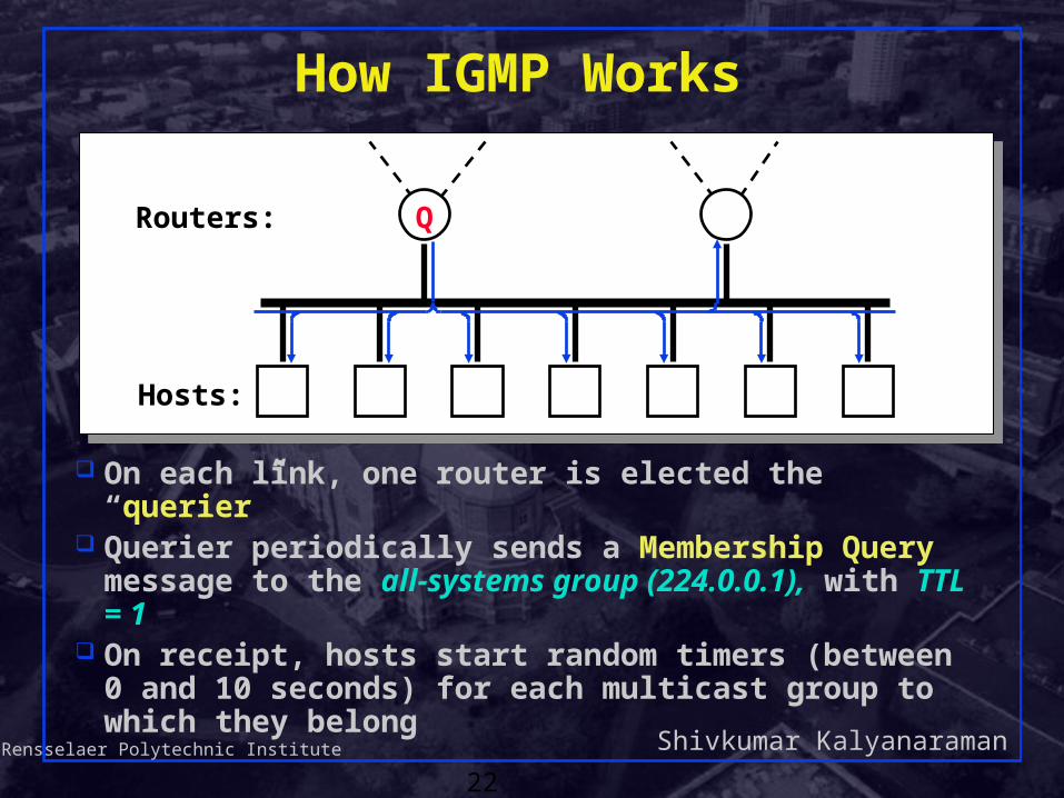
How IGMP Works
On each link, one router is elected the “querier” Querier periodically sends a Membership Query
message to the all-systems group (224.0.0.1), with TTL = 1
On receipt, hosts start random timers (between 0 and 10 seconds) for each multicast group to which they belong
QRouters:
Hosts:

Shivkumar KalyanaramanRensselaer Polytechnic Institute
23
How IGMP Works (cont.)
When a host’s timer for group G expires, it sends a Membership Report to group G, with TTL = 1
Other members of G hear the report and stop (suppress) their timers
Routers hear all reports, and time out non-responding groups
Q
G G G G
Routers:
Hosts:
Shivkumar KalyanaramanRensselaer Polytechnic Institute
24
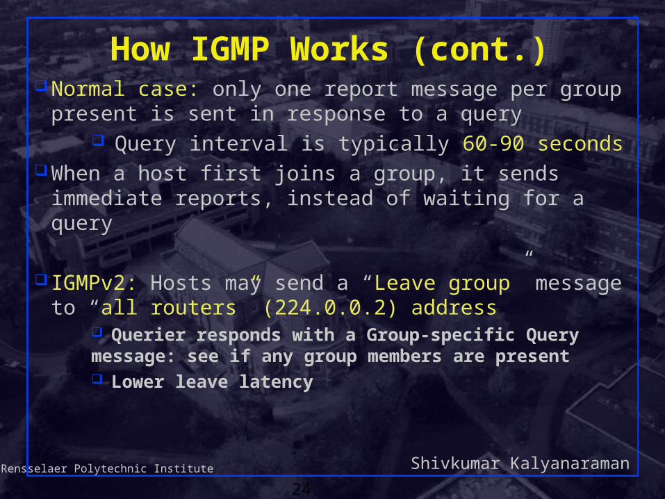
How IGMP Works (cont.) Normal case: only one report message per group
present is sent in response to a query Query interval is typically 60-90 seconds
When a host first joins a group, it sends immediate reports, instead of waiting for a query
IGMPv2: Hosts may send a “Leave group” message to “all routers” (224.0.0.2) address
Querier responds with a Group-specific Query message: see if any group members are present Lower leave latency
Shivkumar KalyanaramanRensselaer Polytechnic Institute
25
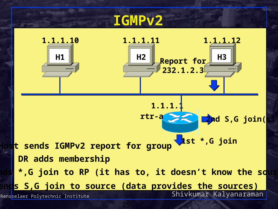
IGMPv2
DR adds membership
1.1.1.1
H1 H3
1.1.1.10 1.1.1.11 1.1.1.12
H3
rtr-a
H2 Report for232.1.2.3
Host sends IGMPv2 report for group1st *,G join
DR sends *,G join to RP (it has to, it doesn’t know the sources)
2nd S,G join(s)
DR sends S,G join to source (data provides the sources)

Shivkumar KalyanaramanRensselaer Polytechnic Institute
26
IGMPv3
1.1.1.1
H1 H3
1.1.1.10 1.1.1.11 1.1.1.12
H3
rtr-a
H2 Report for232.1.2.3
source_list
Host sends IGMPv3 report for group which can specify a list of sources to explicitly include.
DR adds membership.
S,G join(s)
DR sends S,G join directly to sources in the source_list, and is not required to send *,G join to RP (see SSM discussion later)

Shivkumar KalyanaramanRensselaer Polytechnic Institute
27
IP Multicast Architecture
Hosts
Routers
Service model
Host-to-router protocol(IGMP)
Multicast routing protocols

Shivkumar KalyanaramanRensselaer Polytechnic Institute
28
Multicast Routing
Basic objective – build distribution tree for multicast packetsThe “leaves” of the distribution tree are the
subnets containing at least one group member (detected by IGMP)
Multicast service model makes it hardAnonymityDynamic join/leave
Shivkumar KalyanaramanRensselaer Polytechnic Institute
29
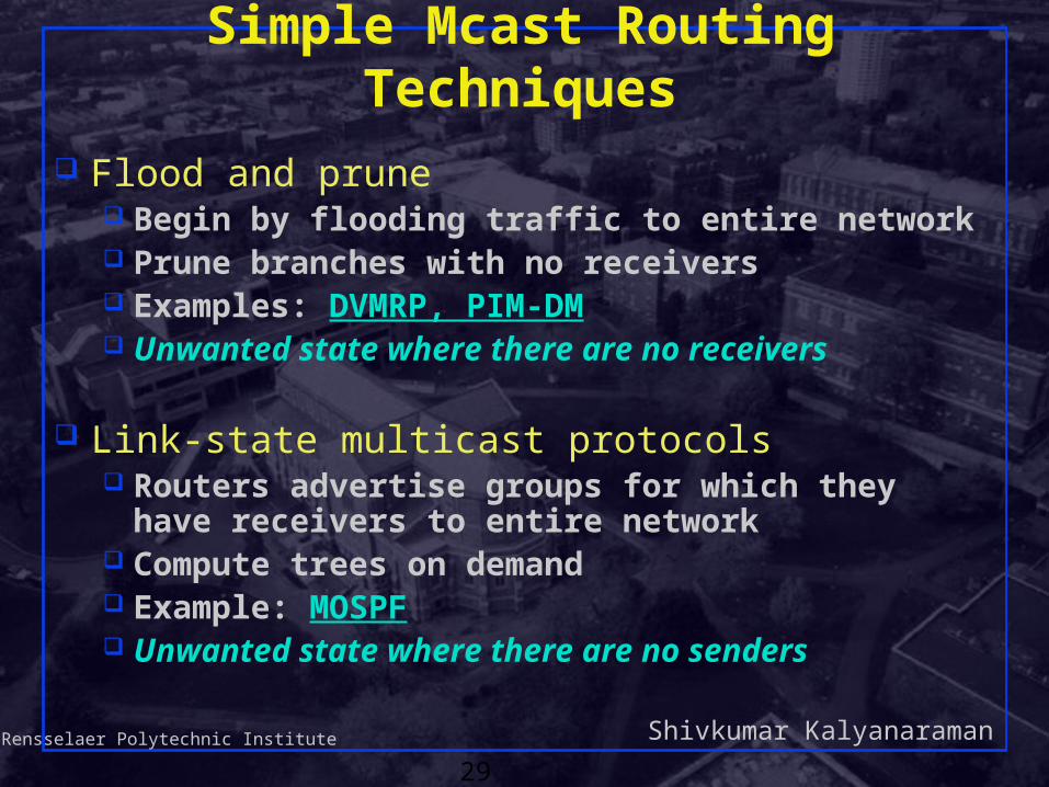
Simple Mcast Routing Techniques
Flood and prune Begin by flooding traffic to entire network Prune branches with no receivers Examples: DVMRP, PIM-DM Unwanted state where there are no receivers
Link-state multicast protocols Routers advertise groups for which they have
receivers to entire network Compute trees on demand Example: MOSPF Unwanted state where there are no senders

Shivkumar KalyanaramanRensselaer Polytechnic Institute
30
How to Flood Efficiently ? A router forwards a packet from source (S) iff it arrives via
the shortest path from the router back to S Reverse path check!
Packet is replicated out all but the incoming interface Reverse shortest paths easy to compute just use info
in DV routing tables DV gives shortest reverse paths Efficient if costs are symmetric xx
yy
tt
SS
a
zz
Forward packets that arriveon shortest path from “t” to “S” (assume symmetric routes)

Shivkumar KalyanaramanRensselaer Polytechnic Institute
31
Problem Flooding can cause a given packet to be sent multiple times
over the same link: can filter better than this!
Solution: Reverse Path Broadcasting
xx yy
zz
SS
a
b
duplicate packet
Shivkumar KalyanaramanRensselaer Polytechnic Institute
32
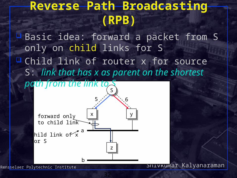
Reverse Path Broadcasting (RPB) Basic idea: forward a packet from S only on
child links for S Child link of router x for source S: link that has x
as parent on the shortest path from the link to S
xx yy
zz
SS
a
b
5 6
child link of xfor S
forward onlyto child link

Shivkumar KalyanaramanRensselaer Polytechnic Institute
33
How to Find Child Links? Routing updates !
If z tells x that it can reach S through y, and if the cost of this path is >= the cost of the path
from z to S through x, then x knows that the link to z is a child link
In case of tie, lower address wins
xx yy
zz
SS
a
b
5 6
child link of xfor S
forward onlyto child link
Shivkumar KalyanaramanRensselaer Polytechnic Institute
34
Problem
This is still a broadcast algorithm – the traffic goes everywhere – lousy filtering!
First order solution: Truncated RPB

Shivkumar KalyanaramanRensselaer Polytechnic Institute
35
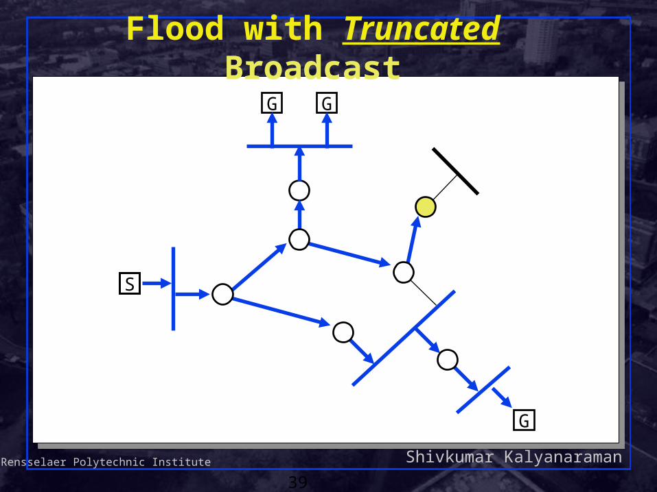
Truncated RPB
Don't forward traffic onto networks with no receivers1. Identify leaves (see below)2. Detect group membership in leaf (IGMP)
Identify leaves Leaf links are the child links that no other
router uses to reach source S Use periodic updates of form:
“this is my next-link to source S” If child is not the “next-link” for anyone, it is a
leaf
Shivkumar KalyanaramanRensselaer Polytechnic Institute
36
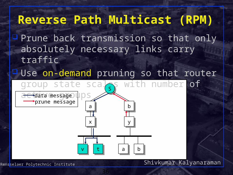
Reverse Path Multicast (RPM) Prune back transmission so that only absolutely
necessary links carry traffic Use on-demand pruning so that router group
state scales with number of active groups
xx yy
tt
SS
vv bbaa
aa bb
data messageprune message

Shivkumar KalyanaramanRensselaer Polytechnic Institute
37
Basic RPM Idea Prune (Source,Group) at leaf if no members
Send Non-Membership Report (NMR) up the tree If all children of router R prune (S,G)
Propagate prune for (S,G) to parent R On timeout:
Prune dropped Flow is reinstated Down stream routers re-prune Note: this is a soft-state approach
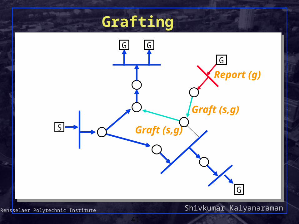
Grafting: Explicitly reinstate sub-tree when IGMP detects new members at leaf, or when a child asks
for a graft.
Shivkumar KalyanaramanRensselaer Polytechnic Institute
38
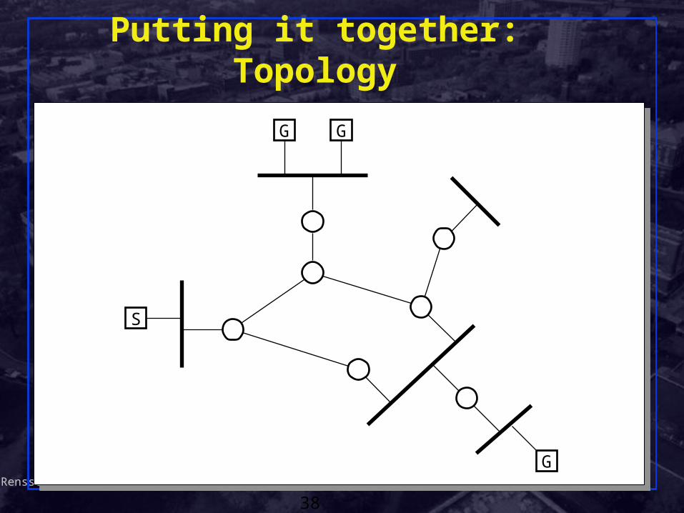
Putting it together: Topology
G G
S
G
Shivkumar KalyanaramanRensselaer Polytechnic Institute
39
Flood with Truncated Broadcast
G G
S
G

Shivkumar KalyanaramanRensselaer Polytechnic Institute
40
PruningG G
S
Prune (s,g)
Prune (s,g)
G
Shivkumar KalyanaramanRensselaer Polytechnic Institute
41
Graft (s,g)
Graft (s,g)
Grafting
G G
S
G
G
Report (g)

Shivkumar KalyanaramanRensselaer Polytechnic Institute
42
After Grafting CompleteG G
S
G
G
Shivkumar KalyanaramanRensselaer Polytechnic Institute
43
Distance-Vector Multicast Routing
DVMRP consists of two major components: A conventional distance-vector routing protocol
(like RIP) A protocol for determining how to forward multicast
packets, based on the unicast routing table
DVMRP router forwards a packet if The packet arrived from the link used to reach the
source of the packetReverse path forwarding check – RPF
Packet forwarded ONLY to child links If downstream links have not pruned the tree
Shivkumar KalyanaramanRensselaer Polytechnic Institute
44
DVMRP limitations
Like distance-vector protocols, affected by count-to-infinity and transient loopingMulticast trees more vulnerable than unicast !
Shares the scaling limitations of RIP. New scaling limitations: (S,G) state in routers: even in pruned parts!Broadcast-and-prune has an initial broadcast.Limited to few senders. Many small groups
also undesired. Why ? No hierarchy: flat routing domain

Shivkumar KalyanaramanRensselaer Polytechnic Institute
45
Multicast Backbone (MBone) An overlay network of IP multicast-capable routers
using DVMRP Tools: sdr (session directory), vic, vat, wb
Host/router
MBone router
Physical linkTunnelPart of MBone
R R
R
H R
H
R
RH

Shivkumar KalyanaramanRensselaer Polytechnic Institute
46
A method for sending multicast packets through multicast-ignorant routers
IP multicast packet is encapsulated in a unicast IP packet (IP-in-IP) addressed to far end of tunnel:
Tunnel acts like a virtual point-to-point link Intermediate routers see only outer header Tunnel endpoint recognizes IP-in-IP (protocol type = 4)
and de-capsulates datagram for processing Each end of tunnel is manually configured with unicast
address of the other end
MBone Tunnels
IP header,dest = unicast
IP header,dest = multicast
Transport headerand data…
Shivkumar KalyanaramanRensselaer Polytechnic Institute
47
Simple Routing Techniques (recall)
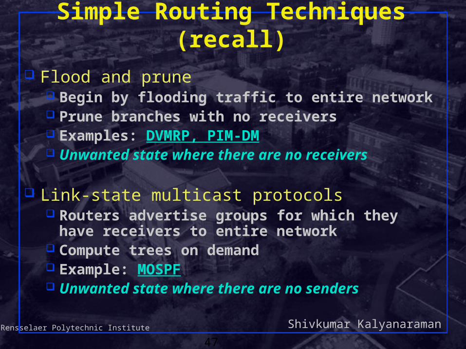
Flood and prune Begin by flooding traffic to entire network Prune branches with no receivers Examples: DVMRP, PIM-DM Unwanted state where there are no receivers
Link-state multicast protocols Routers advertise groups for which they have
receivers to entire network Compute trees on demand Example: MOSPF Unwanted state where there are no senders

Shivkumar KalyanaramanRensselaer Polytechnic Institute
48
Multicast OSPF (MOSPF)
Extend OSPF to support multicastMulticast-capable routers flag link state routing
advertisementsLink-state packets include multicast group
addresses to which local members have joinedRouting algorithm augmented to compute
shortest-path distribution tree from a source to any set of destinations

Shivkumar KalyanaramanRensselaer Polytechnic Institute
49
Source 1
Receiver 1
Receiver 2
MOSPF: Example
Z
W
Q
T
Shivkumar KalyanaramanRensselaer Polytechnic Institute
50
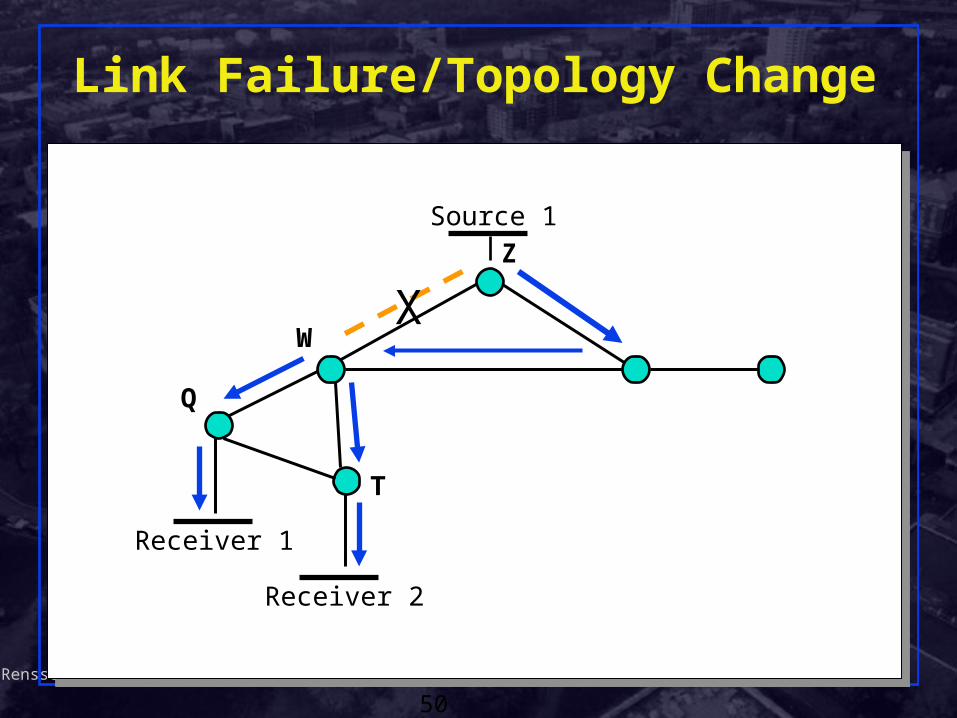
Source 1
Receiver 1
Receiver 2
Link Failure/Topology Change
Z
W
Q
T
X
Shivkumar KalyanaramanRensselaer Polytechnic Institute
51
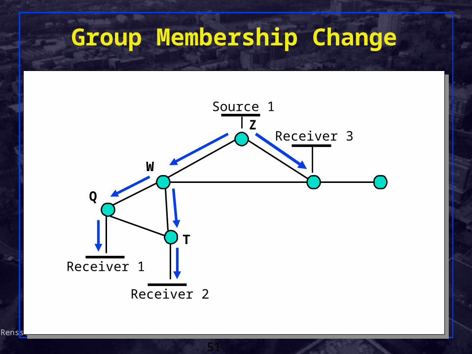
Source 1
Receiver 1
Receiver 2
Group Membership Change
Z
W
Q
T
Receiver 3
Shivkumar KalyanaramanRensselaer Polytechnic Institute
52
MOSPF: Impact on Route Computation
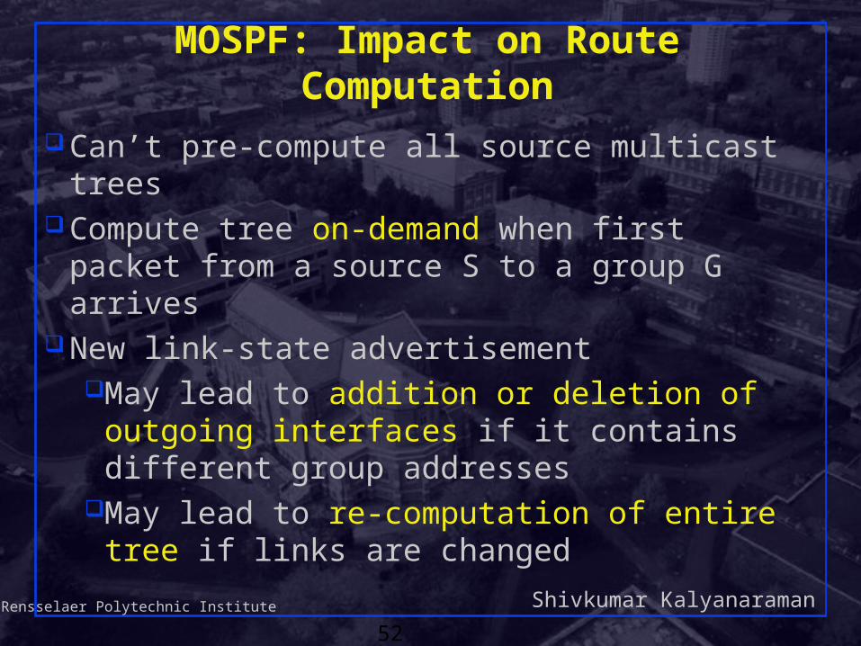
Can’t pre-compute all source multicast treesCompute tree on-demand when first packet from
a source S to a group G arrivesNew link-state advertisement
May lead to addition or deletion of outgoing interfaces if it contains different group addresses
May lead to re-computation of entire tree if links are changed

Shivkumar KalyanaramanRensselaer Polytechnic Institute
53
Routing Techniques (taxonomy)
Tree building methods: Data-driven: calculate the tree only when the first
packet is seen. Eg: DVMRP, MOSPF Control-driven: Build tree in background before
any data is transmitted. Eg: CBT
Join-styles: Explicit-join: The leaves explicitly join the tree. Eg:
CBT, PIM-SM Implicit-join: All subnets are assumed to be
receivers unless they say otherwise (eg via tree pruning). Eg: DVMRP, MOSPF

Shivkumar KalyanaramanRensselaer Polytechnic Institute
54
Shared vs. Source-based Trees
Source-based treesSeparate shortest path tree for each sender (S,G) state at intermediate routersEg: DVMRP, MOSPF, PIM-DM, PIM-SM
Shared treesSingle tree shared by all membersData flows on same tree regardless of sender (*,G) state at intermediate routersEg: CBT, PIM-SM
Shivkumar KalyanaramanRensselaer Polytechnic Institute
55
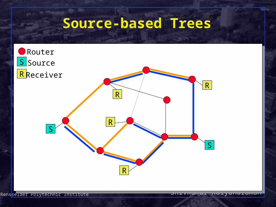
Source-based Trees
Router
Source
Receiver
S
R
R
R
R
R
S
S

Shivkumar KalyanaramanRensselaer Polytechnic Institute
56
A Shared Tree
RPRP
Router
Source
Receiver
S
S
S
R
R
R
R
R

Shivkumar KalyanaramanRensselaer Polytechnic Institute
57
Shared vs. Source-Based Trees Source-based trees
Shortest path trees – low delay, better load distribution
More state at routers (per-source state) Efficient in dense-area multicast
Shared trees Higher delay (bounded by factor of 2), traffic
concentration Choice of core affects efficiency Per-group state at routers Efficient for sparse-area multicast
Shivkumar KalyanaramanRensselaer Polytechnic Institute
58
Core-based Routing Protocols
Specify “meeting place” aka “core” or “rendezvous point (RP)”
Sources send initial packets to core Receivers join group at core Requires mapping between multicast group
address and “meeting place” Examples: CBT, PIM-SM

Shivkumar KalyanaramanRensselaer Polytechnic Institute
59
Protocol Independent Multicast (PIM)
Support for both shared and per-source trees Dense mode (per-source tree)
Similar to DVMRP Sparse mode (shared tree)
Core = rendezvous point (RP) Independent of unicast routing protocol
Just uses unicast forwarding table
Shivkumar KalyanaramanRensselaer Polytechnic Institute
60
PIM Protocol Overview
Basic protocol stepsRouters with local members Join toward
Rendezvous Point (RP) to join shared treeRouters with local sources encapsulate data in
Register messages to RP Routers with local members may initiate data-
driven switch to source-specific shortest path trees
PIM v.2 Specification (RFC2362)

Shivkumar KalyanaramanRensselaer Polytechnic Institute
61
Source 1
Receiver 1
Receiver 2
PIM Example: Build Shared Tree
(*,G)
Receiver 3
(*,G)
(*,G)
(*,G)
(*,G)
(*,G)
Join messagetoward RP
Shared tree after R1,R2 join
RP

Shivkumar KalyanaramanRensselaer Polytechnic Institute
62
Source 1
Receiver 1
Receiver 2
Data Encapsulated in Register
(*,G)
Receiver 3
(*,G)
(*,G)
(*,G)
(*,G)
(*,G)
Unicast encapsulated data packet to RP in Register
RP
RP de-capsulates, forwards down shared tree

Shivkumar KalyanaramanRensselaer Polytechnic Institute
63
Source 1
Receiver 1
Receiver 2
RP Send Join to High Rate Source
Receiver 3
(S1,G)
RP
Join messagetoward S1
Shared tree

Shivkumar KalyanaramanRensselaer Polytechnic Institute
64
Source 1
Receiver 1
Receiver 2
Build Source-Specific Distribution Tree
Receiver 3
Join messages
Shared Tree
RP
Build source-specific tree for high data rate source
(S1,G),(*,G)
(S1, G)
(S1,G),(*,G)(S1,G),(*,G)
Shivkumar KalyanaramanRensselaer Polytechnic Institute
65
Source 1
Receiver 1
Receiver 2
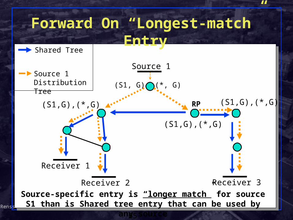
Forward On “Longest-match” Entry
Receiver 3
Source 1 Distribution Tree
Shared Tree
RP
(S1,G),(*,G)
(S1, G)
(S1,G),(*,G)(S1,G),(*,G)
Source-specific entry is “longer match” for source S1 than is Shared tree entry that can be used by any source
(*, G)

Shivkumar KalyanaramanRensselaer Polytechnic Institute
66
Prune S1 off Shared Tree
Prune S1 off shared tree where if S1 and RP entries differ
Source 1
Receiver 1
Receiver 2 Receiver 3
Source 1 Distribution Tree
Shared Tree
RP
Prune S1

Shivkumar KalyanaramanRensselaer Polytechnic Institute
67
Multicast Address Allocation
Unicast IP addressesAllocated statically to hostsAllocated hierarchically by hosts’ org
Multicast IP addressesAllocated per sessionGroups cross admin boundaries
Shivkumar KalyanaramanRensselaer Polytechnic Institute
68
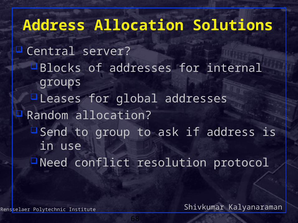
Address Allocation Solutions
Central server?Blocks of addresses for internal groupsLeases for global addresses
Random allocation?Send to group to ask if address is in useNeed conflict resolution protocol

Shivkumar KalyanaramanRensselaer Polytechnic Institute
69
Multicast Address-Set Claim (MASC)
Address allocation goalsEfficient utilization of address spaceAggregation of routing entriesRobust and scalable
Distributed, collaborative allocationDynamic claim and listen protocolClaim “prefixes” from parentCommunicate prefixes to local addresss
allocation

Shivkumar KalyanaramanRensselaer Polytechnic Institute
70
MASC
Domain A224.0.0.0/16
Domain B224.0.128.0/24
Domain C224.0.1.0/24
Domain F Domain G
A1 A1
B1
B2
F1
C1
C2
G1

Shivkumar KalyanaramanRensselaer Polytechnic Institute
71
Prefix Selection
Collect available prefixes Remove those that have been claimed Randomly select one of remaining prefixes with
shortest mask (largest range) Claim first sub-prefix of desired size
Shivkumar KalyanaramanRensselaer Polytechnic Institute
72
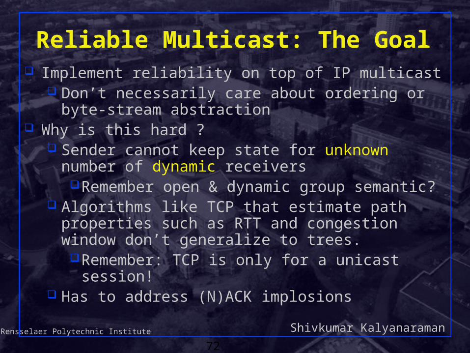
Reliable Multicast: The Goal Implement reliability on top of IP multicast
Don’t necessarily care about ordering or byte-stream abstraction
Why is this hard ? Sender cannot keep state for unknown number of
dynamic receiversRemember open & dynamic group semantic?
Algorithms like TCP that estimate path properties such as RTT and congestion window don’t generalize to trees.
Remember: TCP is only for a unicast session! Has to address (N)ACK implosions

Shivkumar KalyanaramanRensselaer Polytechnic Institute
73
R1
Implosion
S
R3 R4
R2
21
R1
S
R3 R4
R2
Packet 1 is lost All 4 receivers request a resend
Resend request

Shivkumar KalyanaramanRensselaer Polytechnic Institute
74
Retransmission
Re-transmitterOptions: sender, other receivers
How to retransmitUnicast, multicast, scoped multicast,
retransmission group, … Problem: retransmissions (aka repairs) may reach
destinations that don’t require a retransmissionA.k.a “exposure” problemSolution: subcast the re-transmission only to
receivers that need it.

Shivkumar KalyanaramanRensselaer Polytechnic Institute
75
R1
Why Subcast? Exposure problem…
S
R3 R4
R2
21
R1
S
R3 R4
R2
Packet 1 does not reach R1;Receiver 1 requests a resend
Packet 1 resent to all 4 receivers
1
1
Resend request Resent packet
Shivkumar KalyanaramanRensselaer Polytechnic Institute
76
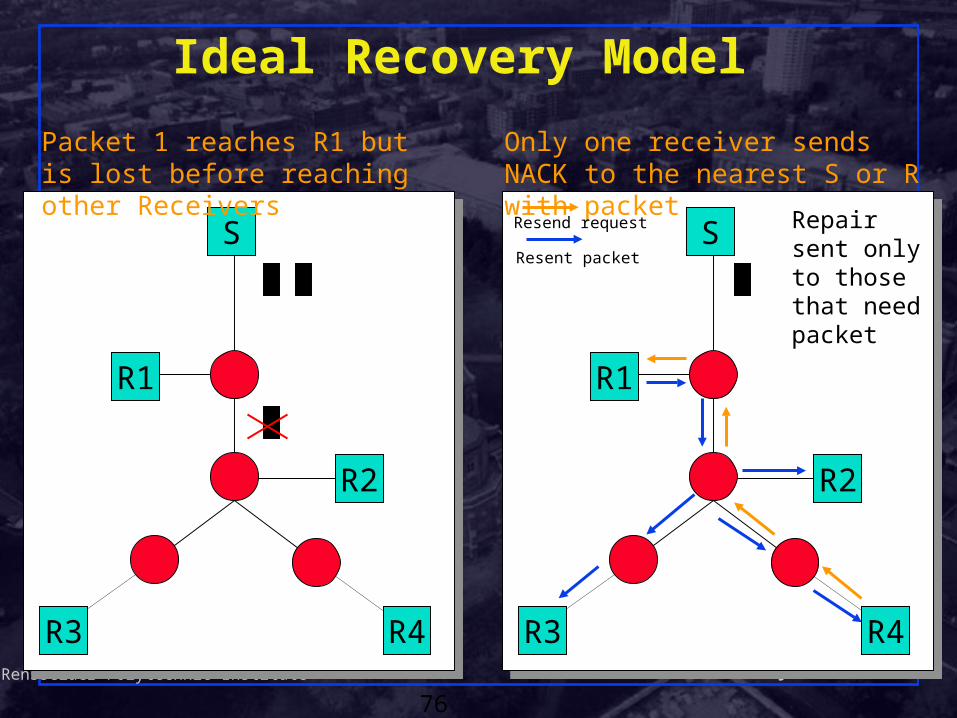
Ideal Recovery Model
S
R3 R4
R2
2
1
S
R3 R4
R2
Packet 1 reaches R1 but is lost before reaching other Receivers
Only one receiver sends NACK to the nearest S or R with packet
Resend request
1 1Resent packet
Repair sent only to those that need packet
R1 R1

Shivkumar KalyanaramanRensselaer Polytechnic Institute
77
R1
Using the Routers
S
R3 R4
R2
• Routers do transport level processing:
• Buffer packets• Combine ACKs• Send retransmissions
• Model solves implosion and exposure, but not scalable
• Violates end-to-end argument
NACK
RTX
Router

Shivkumar KalyanaramanRensselaer Polytechnic Institute
78
Reliable Multicast Transport: Issues Retransmission can make reliable multicast as
inefficient as replicated unicast (N)ACK-implosion if all destinations ack at once “Crying baby”: a bad link affects entire group
Heterogeneity: receivers, links, group sizes Anonymous/Open/Dynamic Group Model:
Source does not know # of destinations, and destinations may vanish
Multicast applications do not need strong reliability of the type provided by TCP. Can tolerate some reordering, delay, etc
Shivkumar KalyanaramanRensselaer Polytechnic Institute
79
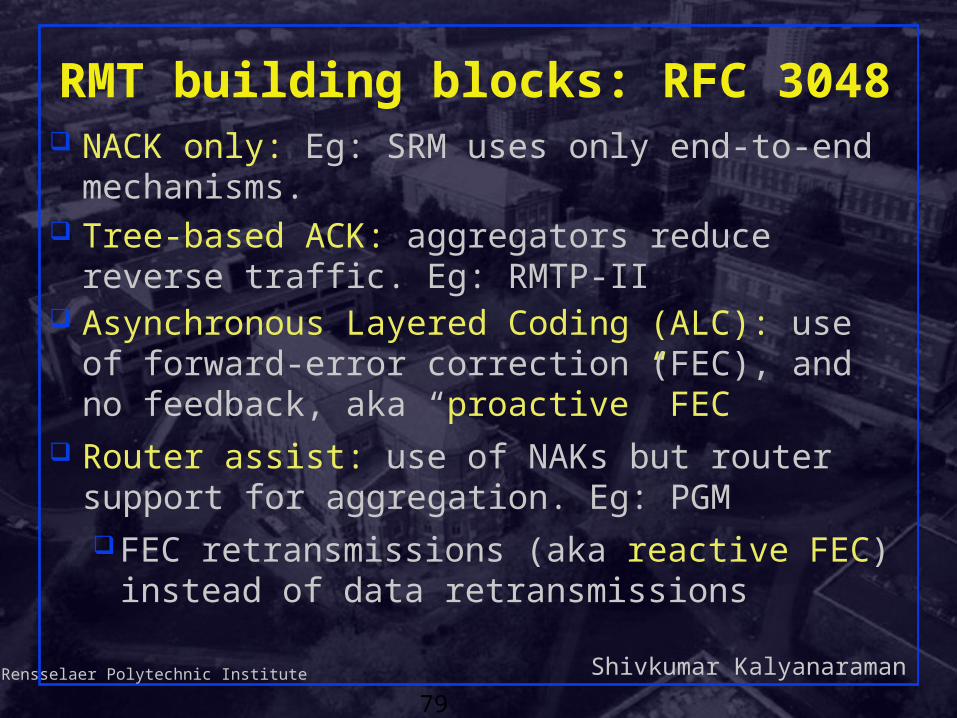
RMT building blocks: RFC 3048 NACK only: Eg: SRM uses only end-to-end
mechanisms. Tree-based ACK: aggregators reduce reverse
traffic. Eg: RMTP-II Asynchronous Layered Coding (ALC): use of
forward-error correction (FEC), and no feedback, aka “proactive” FEC
Router assist: use of NAKs but router support for aggregation. Eg: PGMFEC retransmissions (aka reactive FEC) instead
of data retransmissions

Shivkumar KalyanaramanRensselaer Polytechnic Institute
80
•Ring Algorithm
•ACK & NACK
•Many to Many
•Lowest Scalability
•No Hierarchy
•Multicast NACK & FEC
•Simple to Implement
•Moderate Scalability
•Tree with Hard State
•ACK & NACK & FEC
•Confirmed Delivery
•Requires Configuration
Ring
RMP
Ring
RMP
TRACK
RMTP-II
TRACK
RMTP-II
NACK-Only
SRM
NACK-Only
SRM
Classes of RMT Protocols

Shivkumar KalyanaramanRensselaer Polytechnic Institute
81
•One-level TRACK
•ACK & NACK
•Simple to Implement
•Non Real Time
File Transfer
MFTP
File Transfer
MFTP
•Tree with Soft State
•NACK & FEC
•Scaleable & Auto Config
•Req. New Router Code
Router-Assist
PGM
Router-Assist
PGM
ALC (FEC)
Digital Fountain
ALC (FEC)
Digital Fountain
•No Return Channel
•FEC Only
•Highest Scalability & Supports Hetergeneity
•Best for non real time or semi-reliable video
Classes of RMT Protocols

Shivkumar KalyanaramanRensselaer Polytechnic Institute
82
SRM
Originally designed for wb Receiver-reliable
NACK-based Every member may multicast NACK or
retransmission

Shivkumar KalyanaramanRensselaer Polytechnic Institute
83
R1
SRM Request Suppression
S
R3
R2
21
R1
S
R3
R2
Packet 1 is lost; R1 requests resend to Source and Receivers
Packet 1 is resent; R2 and R3 no longer have to request a resend
1
X
XDelay varies by distance
X
Resend request Resent packet

Shivkumar KalyanaramanRensselaer Polytechnic Institute
84
SRM: Stochastic Suppression
datad
d
d
d
Time
NACK
repair
2d
session msg
0
1
2
3
Delay = U[0,D2] dS,R
= Sender
= Repairer
= Requestor

Shivkumar KalyanaramanRensselaer Polytechnic Institute
85
SRM: Summary All members get all the data that has been sent to the the
multicast group (packet reliability ) Repair requests/responses are multicast. Scope of repair requests/responses can be TTL limited or a
separate “local recovery group” can be formed Techniques to avoid implosion of repair requests, and reduce
control traffic: NAK backoff timers NACK/Retransmission suppression
Delay before sending Delay based on RTT estimation Deterministic + Stochastic components
Periodic session messages Full reliability Estimation of distance matrix among members

Shivkumar KalyanaramanRensselaer Polytechnic Institute
86
RMTP: Fixed Hierarchy Rcvr unicasts periodic ACK to its Designated Receiver (DR) DR unicasts its own ACK to its parent Rcvr chooses closest statically configured (DR) Mcast or unicast retransmission
Based on percentage of requests Scoped mcast for local recovery
D R2
R5
S
R3 R4
R1
R R R R
D
R R
D
D DR R Receiver R* Router

Shivkumar KalyanaramanRensselaer Polytechnic Institute
87
RMTP: Comments
: Heterogeneity Lossy link or slow receiver will only affect a
local region : Position of DR critical
Static hierarchy cannot adapt local recovery zone to loss points
Shivkumar KalyanaramanRensselaer Polytechnic Institute
88
R1
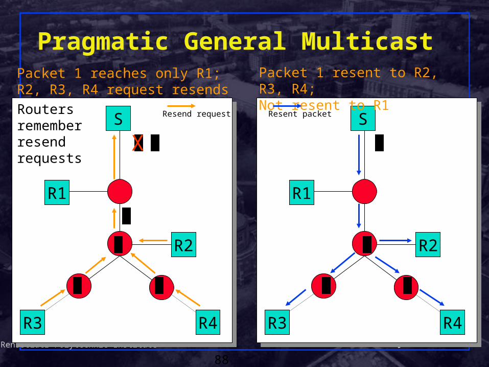
Pragmatic General Multicast
S
R3 R4
R2
21
R1
S
R3 R4
R2
Packet 1 reaches only R1; R2, R3, R4 request resends
Packet 1 resent to R2, R3, R4; Not resent to R1
1
1X
1 1
1
Routers remember resend requests
1 1
1
Resend request Resent packet

Shivkumar KalyanaramanRensselaer Polytechnic Institute
89
ALC Protocol: Digital Fountain
Instead of using a single multicast group, split data over multiple groups Example: Groups at 8, 16, 32, 64, 128, 256 Kbps Receivers can receive from 8 - 504 Kbps
Requires a way of splitting data up Hierarchical video codecs File transfer with Tornado FEC codes
Supports very large and heterogeneous groups, simple to implement
Requires sparse mode routing protocols
Shivkumar KalyanaramanRensselaer Polytechnic Institute
90
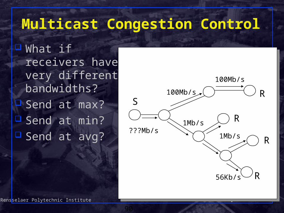
Multicast Congestion Control
What if receivers have very different bandwidths?
Send at max? Send at min? Send at avg?
R
R
R
S
???Mb/s
100Mb/s
100Mb/s
1Mb/s
1Mb/s
56Kb/s
R
Shivkumar KalyanaramanRensselaer Polytechnic Institute
91
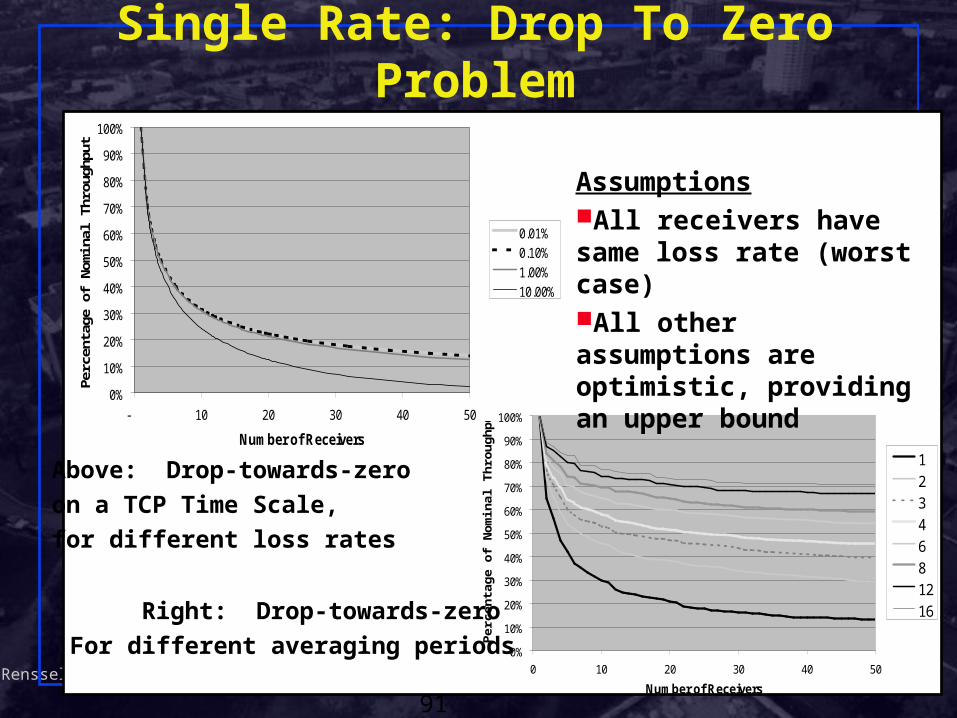
Single Rate: Drop To Zero Problem
0%
10%
20%
30%
40%
50%
60%
70%
80%
90%
100%
- 10 20 30 40 50
Number of Receivers
Perc
enta
ge o
f Nom
inal
Thr
ough
put
0.01%0.10%1.00%10.00%
0%
10%
20%
30%
40%
50%
60%
70%
80%
90%
100%
0 10 20 30 40 50
Number of Receivers
Per
cent
age
of
No
min
al T
hro
ug
hpu
t
1234
681216
Above: Drop-towards-zero
on a TCP Time Scale,
for different loss rates
Right: Drop-towards-zero
For different averaging periods
AssumptionsAll receivers have same loss rate (worst case)All other assumptions are optimistic, providing an upper bound
Shivkumar KalyanaramanRensselaer Polytechnic Institute
92
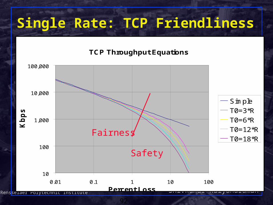
Single Rate: TCP FriendlinessSingle Rate: TCP Friendliness
TCP Throughput Equations
10
100
1,000
10,000
100,000
0.01 0.1 1 10 100
Percent Loss
Kb
ps
Simple
T0=3*R
T0=6*R
T0=12*R
T0=18*RFairness
Safety

Shivkumar KalyanaramanRensselaer Polytechnic Institute
93
PGM Congestion Control (PGMCC)
Receivers measure their loss and RTT The slowest receiver sends back an ACK on
each data packet (I.e. ack clock) The sender runs TCP congestion control
algorithms using these ACKs Results in faster responsiveness but somewhat
high variation in send rate Works well for small groups, or if only a single
receiver at a time is congested

Shivkumar KalyanaramanRensselaer Polytechnic Institute
94
Multi-Rate: Receiver Adaptation Receiver-driven Layered Multicast (RLM)
Layered video encoding Each layer uses its own mcast group
Receiver subscribes to max group that will get through with minimal drops
Dynamically adapt to available capacity Use packet losses as congestion signal On congestion, receivers drop a layer On spare capacity, receivers add a layer Join experiments used for shared learning
Assume no special router support Packets dropped independently of layer

Shivkumar KalyanaramanRensselaer Polytechnic Institute
95
Layered Media Streams
S R
R1R2
R3
R10Mbps
10Mbps
512Kbps
128Kbps
10Mbps
R3 joins layer 1, fails at layer 2
R2 join layer 1,join layer 2 fails at layer 3
R1 joins layer 1,joins layer 2 joins layer 3

Shivkumar KalyanaramanRensselaer Polytechnic Institute
96
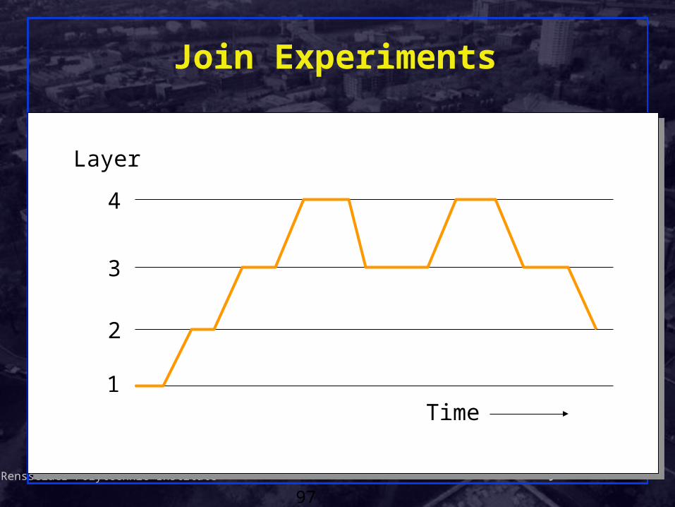
RLM Join Experiment
Receivers periodically try subscribing to higher layer
If enough capacity, no congestion, no drops Keep layer (& try next layer)
If not enough capacity, congestion, drops Drop layer (& increase time to next retry)
What about impact on other receivers?
Shivkumar KalyanaramanRensselaer Polytechnic Institute
97
Join Experiments
1
2
3
4
Time
Layer

Shivkumar KalyanaramanRensselaer Polytechnic Institute
98
RLM Receiver Coordination
Receiver advertises intent to add layer Other receivers
Avoid conflicting experiments If experiment fails, will see increased drops =>
don’t try adding layer! (shared learning)OK to try adding lower layer during higher
layer experimentWon’t cause drops at higher layer!
Shivkumar KalyanaramanRensselaer Polytechnic Institute
99
IP Multicast: Concerns
Deployment is difficult and slow ISP’s reluctant to turn on IP Multicast
Open Group Model: Anyone can join a Group Inter-domain routing: MSDP doesn’t scale Address allocation is also complex PIM-SM requires a Rendezvous Point (RP):
subject to attack Multicast tried to solve too many problems…

Shivkumar KalyanaramanRensselaer Polytechnic Institute
100
Single-Source Multicast (SSM)
Source-specific channel (S,G) only S can send to G another source S’ must use a
separate channel (S’,G) hosts join channels, so a
member joining only (S,G) will NOT receive traffic from S’
Current infrastructure uses Any-Source Multicast (ASM) any source can send to any
group at any time
(S,G) (S’,G)

Shivkumar KalyanaramanRensselaer Polytechnic Institute
101
Why SSM?
Network Operator trivial address allocation (16 million addresses per
host) no network-layer source discovery (PIM RP and/or
MSDP moved to the application layer) overcomes two significant obstacles to deployment
Content Provider exclusive access to multicast groups (no interruptions) permanent multicast groups (easy to advertise) provides better service

Shivkumar KalyanaramanRensselaer Polytechnic Institute
102
source
Problem: How to find the Source?
source

Shivkumar KalyanaramanRensselaer Polytechnic Institute
103
How to Find the Sources? broadcast everywhere
receivers decide when they do not want the traffic
any source multicast (ASM) [PIM-SM/MBGP/MSDP/IGMPv2]
use a rendezvous point (RP) receivers send joins along reverse path to RPsources send traffic to RP
source specific multicast (SSM) [PIM/MBGP/IGMPv3] require receivers to already know source(s)use some out-of-band mechanism

Shivkumar KalyanaramanRensselaer Polytechnic Institute
104
How MSDP works with PIM-SM
RP
RP
RP
RP
MSDP peer
Physical link
A
B
C D
Receiver
Source
PIM message
MSDP message
SA
SA
SA
JoinJoinJoin
Join
Join

Shivkumar KalyanaramanRensselaer Polytechnic Institute
105
How SSM Works
Physical link
A
B
C D
Receiver
Source
PIM message
Join
JoinJoin
Join
Join
Join

Shivkumar KalyanaramanRensselaer Polytechnic Institute
106
SSM Advantages (cont’d)
No RP, No need for MSDP All joins are (S,G), so no need for Class D address
allocation Receivers find out about sources through out-of-band
means (such as a web site) SSM-only implementations are much simpler than the full
PIM-SM No RP, No Bootstrap RP Election No Register state machine No need to keep (*,G), (S,G,rpt) and (*,*,RP) state No (*,G) Assert State
Shivkumar KalyanaramanRensselaer Polytechnic Institute
107
Application-level Multicast
Do we really need network level multicast?EfficiencyLogical rendezvous
Can we get efficiency by creatively using the actual members or a few infrastructure nodes?

Shivkumar KalyanaramanRensselaer Polytechnic Institute
108
Application-level Multicast
S
R3 R4
R2
S
R3 R4
R2

Shivkumar KalyanaramanRensselaer Polytechnic Institute
109
Narada: End System Multicast
Stanford
CMU
Stan1
Stan2
Berk2
Overlay TreeGatech
Berk1
Berkeley
GatechStan1
Stan2
CMU
Berk1
Berk2

Shivkumar KalyanaramanRensselaer Polytechnic Institute
110
Performance Concerns
Duplicate Packets:
Bandwidth Wastage
CMU
Stan1
Stan2
Berk2
Gatech
Berk1
Delay from CMU to
Berk1 increases
Stanford
Berkeley
GatechStan1
Stan2
CMU
Berk1
Berk2

Shivkumar KalyanaramanRensselaer Polytechnic Institute
111
Overlay Tree The delay between the source and receivers is small Ideally, the number of redundant packets on any physical
link is low Heuristic:
Every member in the tree has a small degree Degree chosen to reflect bandwidth of connection to
Internet
Gatech
“Efficient” overlay
CMU
Berk2
Stan1
Stan2
Berk1Berk1
High degree (unicast)
Berk2
Gatech
Stan2CMU
Stan1
Stan2
High latency
CMU
Berk2
Gatech
Stan1
Berk1
Shivkumar KalyanaramanRensselaer Polytechnic Institute
112
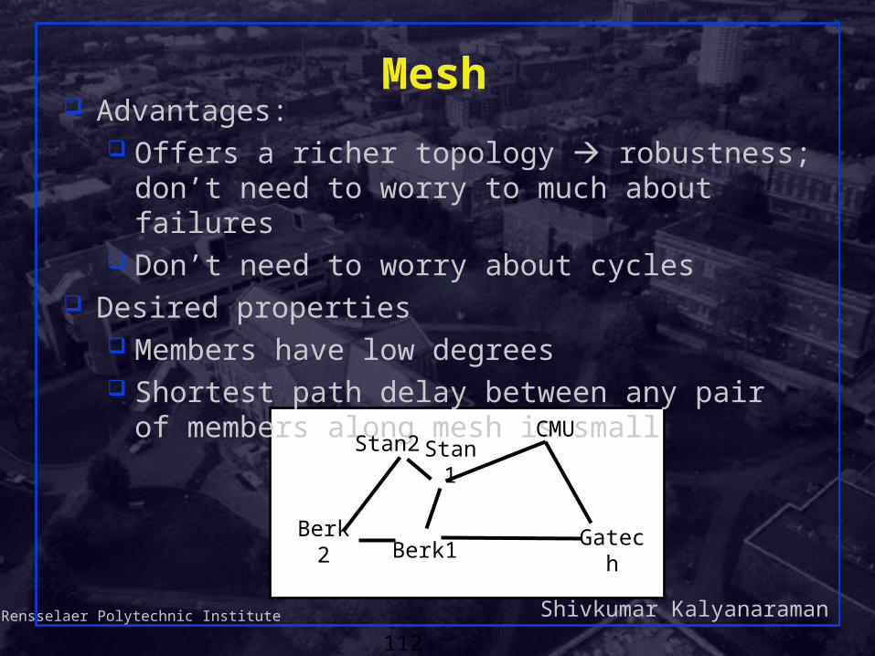
Mesh Advantages:
Offers a richer topology robustness; don’t need to worry to much about failures
Don’t need to worry about cycles Desired properties
Members have low degrees Shortest path delay between any pair of members
along mesh is small
Berk2 Berk1
CMU
Gatech
Stan1Stan2

Shivkumar KalyanaramanRensselaer Polytechnic Institute
113
Overlay Trees
Source routed minimum spanning tree on mesh Desired properties
Members have low degreeSmall delays from source to receivers
Berk2 GatechBerk1
Stan1Stan2
Berk2 Berk1
CMU
Gatech
Stan1Stan2

Shivkumar KalyanaramanRensselaer Polytechnic Institute
114
Summary
IP multicast issues and applications Multicast over LANs and scoping IGMP Multicast Routing and MBONE Reliable multicast transports Multicast Congestion Control SSM, Overlay Multicast