Embed Size (px)
Citation preview

Shivkumar KalyanaramanRensselaer Polytechnic Institute
1
IP Multicast
Shivkumar Kalyanaraman
http://www.ecse.rpi.edu/Homepages/shivkumaAdapted in part from Srini Seshan’s (CMU) slides
Shivkumar KalyanaramanRensselaer Polytechnic Institute
2
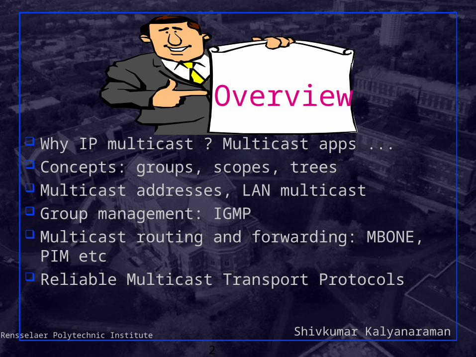
Why IP multicast ? Multicast apps ... Concepts: groups, scopes, trees Multicast addresses, LAN multicast Group management: IGMP Multicast routing and forwarding: MBONE, PIM etc Reliable Multicast Transport Protocols
Overview

Shivkumar KalyanaramanRensselaer Polytechnic Institute
3
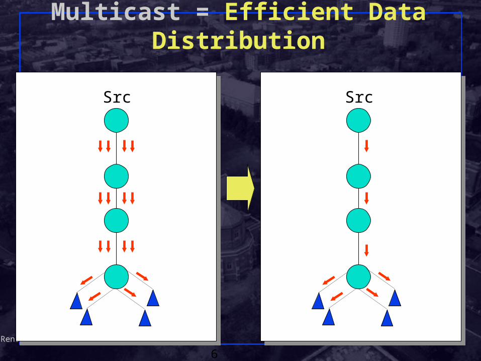
Why IP multicast ? Need for efficient delivery to multiple destinations
across inter/intranets Broadcast:
Send a copy to every machine on the netSimple, but inefficientAll nodes “must” process the packet even if they
don’t careWastes more CPU cycles of slower machines
(“broadcast radiation”)Network loops lead to “broadcast storms”

Shivkumar KalyanaramanRensselaer Polytechnic Institute
4
Why IP multicast ? (Continued)
Replicated Unicast:Sender sends a copy to each receiver in turnReceivers need to register or sender must be
pre-configuredSender is focal point of all control trafficLatency = time between the first and last
receiver getting a copy {can be large if transmission times are large}

Shivkumar KalyanaramanRensselaer Polytechnic Institute
5
Why IP multicast ? Application-layer relays:
A “relay” node or set of nodes does the replicated unicast function instead of the source
Multiple relays can handle “groups” of receivers and reduce number of packets per multicast => efficiency
Manager has to manually configure names of receivers in relays etc => too much administrative burden
Becoming more popular in content distribution
Alternative: build replication/multicast engine at the network layer
Shivkumar KalyanaramanRensselaer Polytechnic Institute
6
Multicast = Efficient Data Distribution
Src Src

Shivkumar KalyanaramanRensselaer Polytechnic Institute
7
Multicast Applications News/sports/stock/weather updates Distance learning Configuration, routing updates, service location Pointcast-type “push” apps Teleconferencing (audio, video, shared whiteboard,
text editor) Distributed interactive gaming or simulations Email distribution lists Content distribution; Software distribution Web-cache updates Database replication

Shivkumar KalyanaramanRensselaer Polytechnic Institute
8
Multicast Apps Characteristics Number of (simultaneous) senders to the group The size of the groups
Number of members (receivers)Geographic extent or scopeDiameter of the group measured in router
hops

Shivkumar KalyanaramanRensselaer Polytechnic Institute
9
Multicast Apps Characteristics (Continued)
The longevity of the group Number of aggregate packets/second The peak/average used by source Level of human interactivity
Lecture mode vs interactiveData-only (eg database replication) vs
multimedia

Shivkumar KalyanaramanRensselaer Polytechnic Institute
10
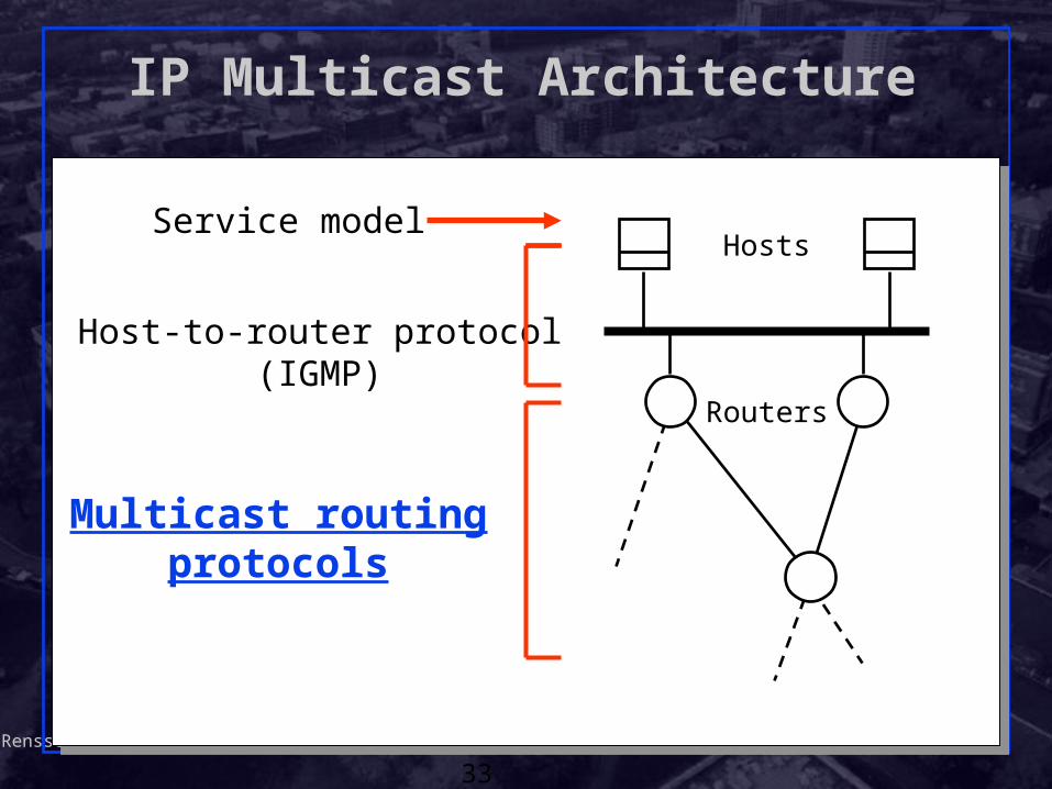
IP Multicast Architecture
Hosts
Routers
Service modelService model
Host-to-router protocol(IGMP)
Multicast routing protocols(various)

Shivkumar KalyanaramanRensselaer Polytechnic Institute
11
IP Multicast model: RFC 1112 Message sent to multicast “group” (of receivers)
Senders need not be group membersA group identified by a single “group address”
Use “group address” instead of destination address in IP packet sent to group
Groups can have any size;Group members can be located anywhere on
the InternetGroup membership is not explicitly knownReceivers can join/leave at will

Shivkumar KalyanaramanRensselaer Polytechnic Institute
12
IP Multicast Concepts (Continued) Packets are not duplicated or delivered to
destinations outside the group Distribution tree constructed for delivery of packets Packets forwarded “away” from the source No more than one copy of packet appears on any
subnet Packets delivered only to “interested” receivers =>
multicast delivery tree changes dynamically Network has to actively discover paths between
senders and receivers

Shivkumar KalyanaramanRensselaer Polytechnic Institute
13
IP Multicast Addresses Class D IP addresses
224.0.0.0 – 239.255.255.255
Address allocation: Well-known (reserved) multicast addresses, assigned
by IANA: 224.0.0.x and 224.0.1.x Transient multicast addresses, assigned and reclaimed dynamically, e.g., by “sdr” program
Each multicast address represents a group of arbitrary size, called a “host group”
There is no structure within class D address space like subnetting => flat address space
1 1 1 0 Group ID

Shivkumar KalyanaramanRensselaer Polytechnic Institute
14
IP Multicast Service — Sending
Uses normal IP-Send operation, with an IP multicast address specified as the destination
Must provide sending application a way to:Specify outgoing network interface, if >1
availableSpecify IP time-to-live (TTL) on outgoing
packetEnable/disable loop-back if the sending host
is/isnt a member of the destination group on the outgoing interface

Shivkumar KalyanaramanRensselaer Polytechnic Institute
15
IP Multicast Service — Receiving
Two new operationsJoin-IP-Multicast-Group(group-address,
interface)Leave-IP-Multicast-Group(group-address,
interface) Receive multicast packets for joined groups via
normal IP-Receive operation

Shivkumar KalyanaramanRensselaer Polytechnic Institute
16
Link-Layer Transmission/Reception Transmission
• IP multicast packet is transmitted as a link-layer multicast, on those links that support multicast
• Link-layer destination address is determined by an algorithm specific to the type of link
• Reception• Necessary steps are taken to receive desired
multicasts on a particular link, such as modifying address reception filters on LAN interfaces
• Multicast routers must be able to receive all IP multicasts on a link, without knowing in advance which groups will be used

Shivkumar KalyanaramanRensselaer Polytechnic Institute
17
Using Link-Layer Multicast Addresses Ethernet and other LANs using 802 addresses:
Direct mapping! Simpler than unicast! No ARP etc. 32 class D addrs may map to one MAC addr
Special OUI for IETF: 0x01-00-5E. No mapping needed for point-to-point links
LAN multicast address
0 0 0 0 0 0 0 1 0 0 0 0 0 0 0 0 0 1 0 1 1 1 1 0 0
1 1 1 0 28 bits
23 bits
IP multicast address
Group bit

Shivkumar KalyanaramanRensselaer Polytechnic Institute
18
Multicast over LANs & Scoping Multicasts are flooded across MAC-layer bridges
along a spanning treeBut flooding may steal sending opportunity for
non-member stations which want to transmitAlmost like broadcast!
Scope: How far do transmissions propagate? Implicit scoping: Reserved Mcast addresses =>
don’t leave subnet. Also called “link-local” addresses

Shivkumar KalyanaramanRensselaer Polytechnic Institute
19
Scope of Multicast Forwarding TTL-based scoping:
Multicast routers have a configured TTL threshold Mcast datagram dropped if TTL <= TTL threshold Useful as a blanket parameter.
Administrative scoping: Use a portion of class D address space (239.0.0.0
thru 239.255.255.255) Truly local to admin domain; address reuse
possible. In IPv6, scoping is an internal attribute of an IPv6
multicast address
Shivkumar KalyanaramanRensselaer Polytechnic Institute
20
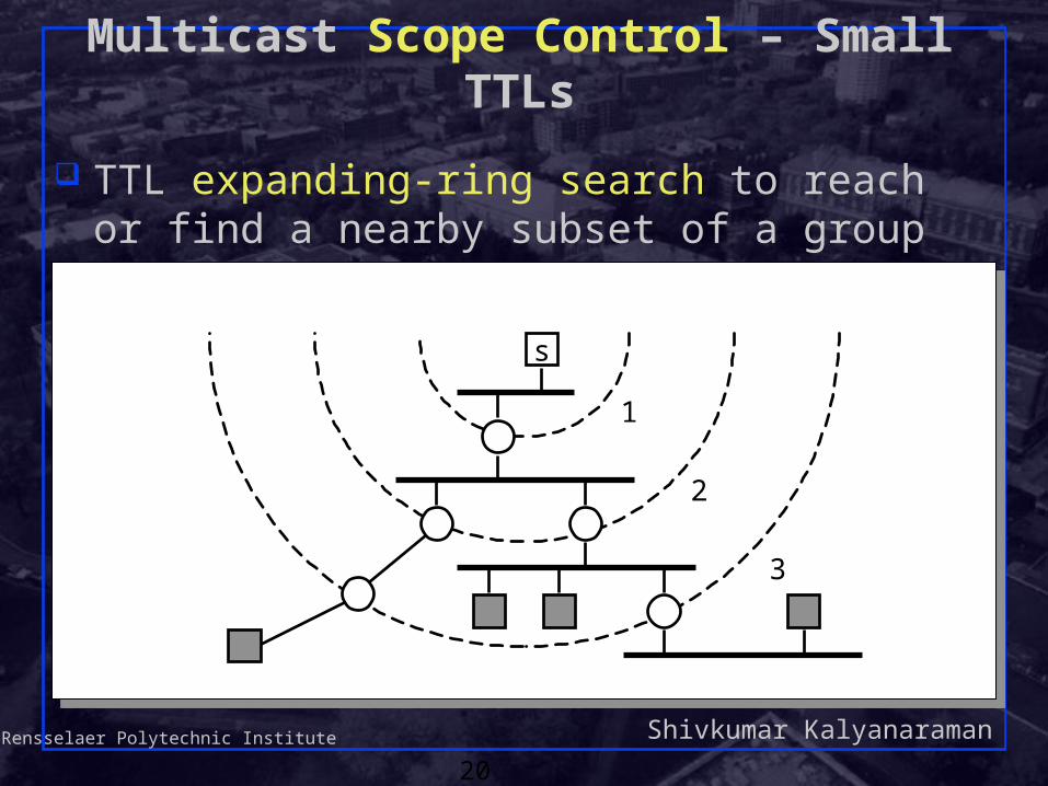
Multicast Scope Control – Small TTLs
TTL expanding-ring search to reach or find a nearby subset of a group
s
1
2
3

Shivkumar KalyanaramanRensselaer Polytechnic Institute
21
Multicast Scope Control – Large TTLs
Administrative TTL Boundaries to keep multicast traffic within an administrative domain, e.g., for privacy or resource reasons
An administrative domain
TTL threshold set oninterfaces to these links,greater than the diameterof the admin. domain
The rest of the Internet

Shivkumar KalyanaramanRensselaer Polytechnic Institute
22
Multicast Scope Control
Administratively-Scoped Addresses (RFC 1112 ) Uses address range 239.0.0.0 — 239.255.255.255 Supports overlapping (not just nested) domains
An administrative domain
The rest of the Internet
address boundary set oninterfaces to these links

Shivkumar KalyanaramanRensselaer Polytechnic Institute
23
IP Multicast Architecture
Hosts
Routers
Service model
Host-to-router protocolHost-to-router protocol(IGMP)(IGMP)
Multicast routing protocols(various)

Shivkumar KalyanaramanRensselaer Polytechnic Institute
24
Internet Group Management Protocol
IGMP: “signaling” protocol to establish, maintain, remove groups on a subnet.
Objective: keep router up-to-date with group membership of entire LANRouters need not know who all the members
are, only that members exist Each host keeps track of which mcast groups are
subscribed toSocket API informs IGMP process of all joins

Shivkumar KalyanaramanRensselaer Polytechnic Institute
25
How IGMP Works
On each link, one router is elected the “querier” Querier periodically sends a Membership Query
message to the all-systems group (224.0.0.1), with TTL = 1
On receipt, hosts start random timers (between 0 and 10 seconds) for each multicast group to which they belong
QRouters:
Hosts:

Shivkumar KalyanaramanRensselaer Polytechnic Institute
26
How IGMP Works (cont.)
When a host’s timer for group G expires, it sends a Membership Report to group G, with TTL = 1
Other members of G hear the report and stop (suppress) their timers
Routers hear all reports, and time out non-responding groups
Q
G G G G
Routers:
Hosts:
Shivkumar KalyanaramanRensselaer Polytechnic Institute
27
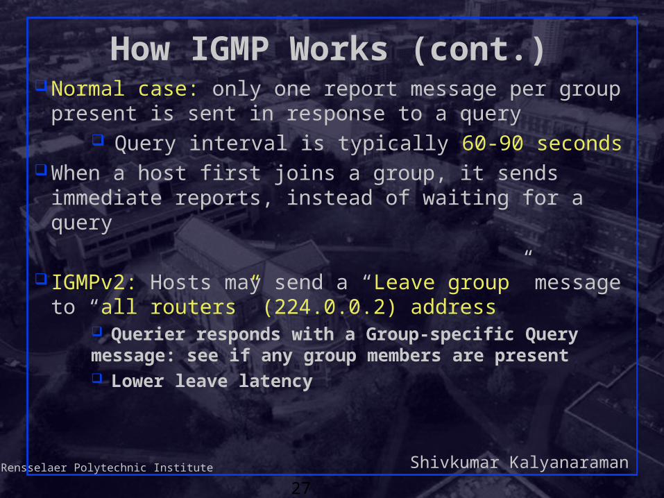
How IGMP Works (cont.) Normal case: only one report message per group
present is sent in response to a query Query interval is typically 60-90 seconds
When a host first joins a group, it sends immediate reports, instead of waiting for a query
IGMPv2: Hosts may send a “Leave group” message to “all routers” (224.0.0.2) address
Querier responds with a Group-specific Query message: see if any group members are present Lower leave latency

Shivkumar KalyanaramanRensselaer Polytechnic Institute
28
IP Multicast Architecture
Hosts
Routers
Service model
Host-to-router protocol(IGMP)
Multicast routing protocols(various)

Shivkumar KalyanaramanRensselaer Polytechnic Institute
29
Internet Group Management Protocol
End system to router protocol is IGMP Each host keeps track of which mcast groups are
subscribed toSocket API informs IGMP process of all joins
Objective is to keep router up-to-date with group membership of entire LANRouters need not know who all the members
are, only that members exist

Shivkumar KalyanaramanRensselaer Polytechnic Institute
30
How IGMP Works
On each link, one router is elected the “querier” Querier periodically sends a Membership Query message to the
all-systems group (224.0.0.1), with TTL = 1 On receipt, hosts start random timers (between 0 and 10
seconds) for each multicast group to which they belong
QRouters:
Hosts:

Shivkumar KalyanaramanRensselaer Polytechnic Institute
31
How IGMP Works (cont.)
When a host’s timer for group G expires, it sends a Membership Report to group G, with TTL = 1
Other members of G hear the report and stop their timers Routers hear all reports, and time out non-responding groups
Q
G G G G
Routers:
Hosts:

Shivkumar KalyanaramanRensselaer Polytechnic Institute
32
How IGMP Works (cont.)
Note that, in normal case, only one report message per group present is sent in response to a query
Query interval is typically 60-90 seconds
When a host first joins a group, it sends one or two immediate reports, instead of waiting for a query
Shivkumar KalyanaramanRensselaer Polytechnic Institute
33
IP Multicast Architecture
Hosts
Routers
Service model
Host-to-router protocol(IGMP)
Multicast routing protocols

Shivkumar KalyanaramanRensselaer Polytechnic Institute
34
Multicast Routing
Basic objective – build distribution tree for multicast packetsThe “leaves” of the distribution tree are the
subnets containing at least one group member (detected by IGMP)
Multicast service model makes it hardAnonymityDynamic join/leave

Shivkumar KalyanaramanRensselaer Polytechnic Institute
35
Routing Techniques
Flood and prune Begin by flooding traffic to entire network Prune branches with no receivers Examples: DVMRP, PIM-DM Unwanted state where there are no receivers
Link-state multicast protocols Routers advertise groups for which they have
receivers to entire network Compute trees on demand Example: MOSPF Unwanted state where there are no senders

Shivkumar KalyanaramanRensselaer Polytechnic Institute
36
Routing Techniques
Core-based protocolsSpecify “meeting place” aka “core” or
“rendezvous point (RP)”Sources send initial packets to coreReceivers join group at coreRequires mapping between multicast group
address and “meeting place” Examples: CBT, PIM-SM

Shivkumar KalyanaramanRensselaer Polytechnic Institute
37
Routing Techniques (Continued) Tree building methods:
Data-driven: calculate the tree only when the first packet is seen. Eg: DVMRP, MOSPF
Control-driven: Build tree in background before any data is transmitted. Eg: CBT
Join-styles: Explicit-join: The leaves explicitly join the tree. Eg:
CBT, PIM-SM Implicit-join: All subnets are assumed to be
receivers unless they say otherwise (eg via tree pruning). Eg: DVMRP, MOSPF
Shivkumar KalyanaramanRensselaer Polytechnic Institute
38
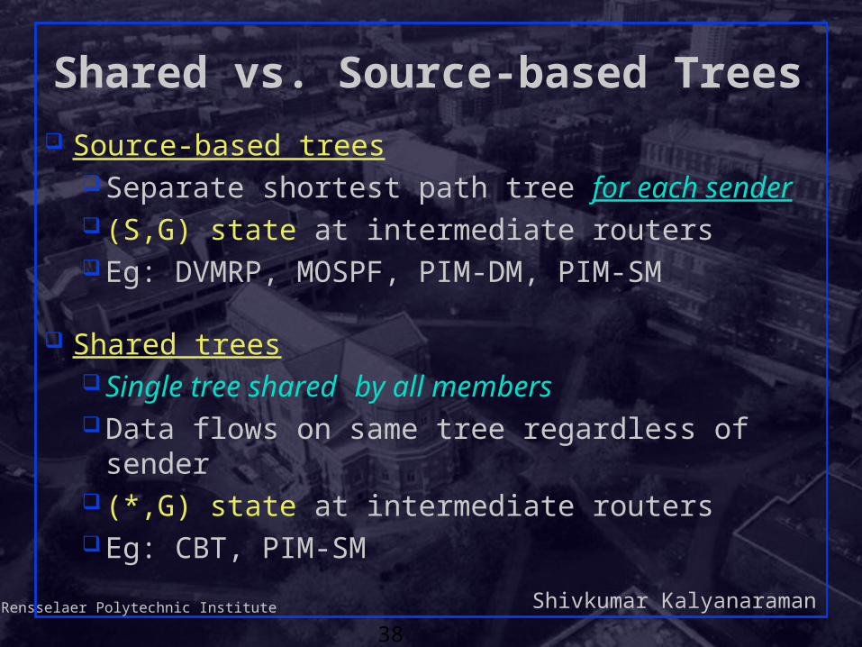
Shared vs. Source-based Trees
Source-based treesSeparate shortest path tree for each sender (S,G) state at intermediate routersEg: DVMRP, MOSPF, PIM-DM, PIM-SM
Shared treesSingle tree shared by all membersData flows on same tree regardless of sender (*,G) state at intermediate routersEg: CBT, PIM-SM

Shivkumar KalyanaramanRensselaer Polytechnic Institute
39
Source-based Trees
Router
Source
Receiver
S
R
R
R
R
R
S
S

Shivkumar KalyanaramanRensselaer Polytechnic Institute
40
A Shared Tree
RPRP
Router
Source
Receiver
S
S
S
R
R
R
R
R

Shivkumar KalyanaramanRensselaer Polytechnic Institute
41
Shared vs. Source-Based Trees Source-based trees
Shortest path trees – low delay, better load distribution
More state at routers (per-source state) Efficient in dense-area multicast
Shared trees Higher delay (bounded by factor of 2), traffic
concentration Choice of core affects efficiency Per-group state at routers Efficient for sparse-area multicast
Shivkumar KalyanaramanRensselaer Polytechnic Institute
42
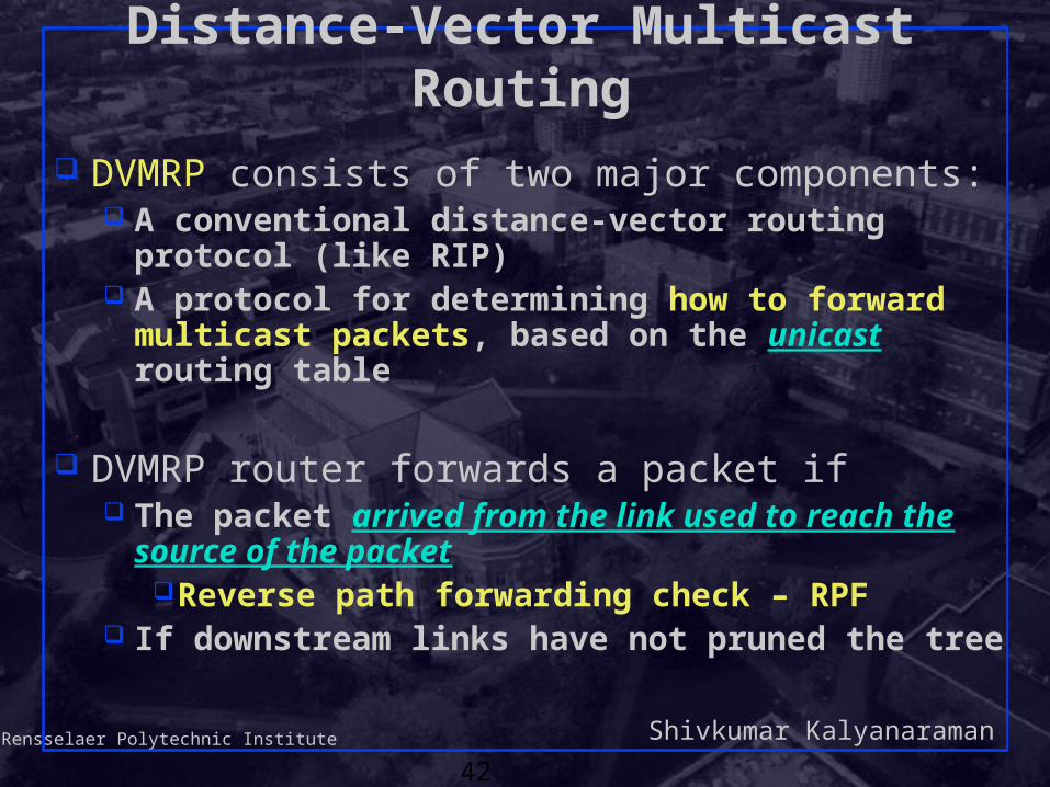
Distance-Vector Multicast Routing
DVMRP consists of two major components: A conventional distance-vector routing protocol
(like RIP) A protocol for determining how to forward
multicast packets, based on the unicast routing table
DVMRP router forwards a packet if The packet arrived from the link used to reach the
source of the packetReverse path forwarding check – RPF
If downstream links have not pruned the tree
Shivkumar KalyanaramanRensselaer Polytechnic Institute
43
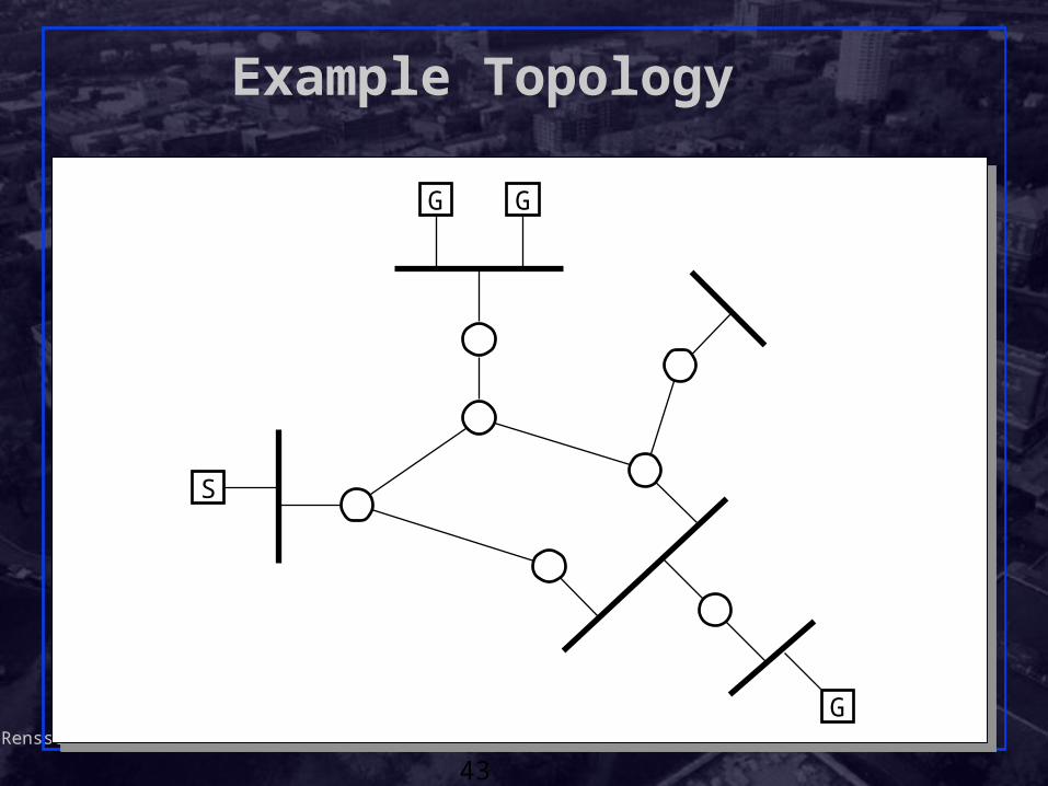
Example Topology
G G
S
G

Shivkumar KalyanaramanRensselaer Polytechnic Institute
44
Flood with Truncated Broadcast
G G
S
G

Shivkumar KalyanaramanRensselaer Polytechnic Institute
45
PruneG G
S
Prune (s,g)
Prune (s,g)
G

Shivkumar KalyanaramanRensselaer Polytechnic Institute
46
Graft (s,g)
Graft (s,g)
Graft
G G
S
G
G
Report (g)

Shivkumar KalyanaramanRensselaer Polytechnic Institute
47
Steady StateG G
S
G
G

Shivkumar KalyanaramanRensselaer Polytechnic Institute
48
DVMRP limitations
Like distance-vector protocols, affected by count-to-infinity and transient loopingMulticast trees more vulnerable than unicast !
Shares the scaling limitations of RIP. New scaling limitations: (S,G) state in routers: even in pruned parts!Broadcast-and-prune has an initial broadcast.Limited to few senders. Many small groups
also undesired. Why ? No hierarchy: flat routing domain

Shivkumar KalyanaramanRensselaer Polytechnic Institute
49
Multicast Backbone (MBone) An overlay network of IP multicast-capable routers
using DVMRP Tools: sdr (session directory), vic, vat, wb
Host/router
MBone router
Physical linkTunnelPart of MBone
R R
R
H R
H
R
RH

Shivkumar KalyanaramanRensselaer Polytechnic Institute
50
A method for sending multicast packets through multicast-ignorant routers
IP multicast packet is encapsulated in a unicast IP packet (IP-in-IP) addressed to far end of tunnel:
Tunnel acts like a virtual point-to-point linkIntermediate routers see only outer header Tunnel endpoint recognizes IP-in-IP (protocol type = 4)
and de-capsulates datagram for processing Each end of tunnel is manually configured with unicast
address of the other end
MBone Tunnels
IP header,dest = unicast
IP header,dest = multicast
Transport headerand data…

Shivkumar KalyanaramanRensselaer Polytechnic Institute
51
Protocol Independent Multicast (PIM)
Support for both shared and per-source trees Dense mode (per-source tree)
Similar to DVMRP Sparse mode (shared tree)
Core = rendezvous point (RP) Independent of unicast routing protocol
Just uses unicast forwarding table

Shivkumar KalyanaramanRensselaer Polytechnic Institute
52
PIM Protocol Overview
Basic protocol stepsRouters with local members Join toward
Rendezvous Point (RP) to join shared treeRouters with local sources encapsulate data in
Register messages to RP Routers with local members may initiate data-
driven switch to source-specific shortest path trees
PIM v.2 Specification (RFC2362)

Shivkumar KalyanaramanRensselaer Polytechnic Institute
53
Source 1
Receiver 1
Receiver 2
PIM Example: Build Shared Tree
(*,G)
Receiver 3
(*,G)
(*,G)
(*,G)
(*,G)
(*,G)
Join messagetoward RP
Shared tree after R1,R2 join
RP

Shivkumar KalyanaramanRensselaer Polytechnic Institute
54
Source 1
Receiver 1
Receiver 2
Data Encapsulated in Register
(*,G)
Receiver 3
(*,G)
(*,G)
(*,G)
(*,G)
(*,G)
Unicast encapsulated data packet to RP in Register
RP
RP de-capsulates, forwards down shared tree

Shivkumar KalyanaramanRensselaer Polytechnic Institute
55
Source 1
Receiver 1
Receiver 2
RP Send Join to High Rate Source
Receiver 3
(S1,G)
RP
Join messagetoward S1
Shared tree

Shivkumar KalyanaramanRensselaer Polytechnic Institute
56
Source 1
Receiver 1
Receiver 2
Build Source-Specific Distribution Tree
Receiver 3
Join messages
Shared Tree
RP
Build source-specific tree for high data rate source
(S1,G),(*,G)
(S1, G)
(S1,G),(*,G)(S1,G),(*,G)

Shivkumar KalyanaramanRensselaer Polytechnic Institute
57
Source 1
Receiver 1
Receiver 2
Forward On “Longest-match” Entry
Receiver 3
Source 1 Distribution Tree
Shared Tree
RP
(S1,G),(*,G)
(S1, G)
(S1,G),(*,G)(S1,G),(*,G)
Source-specific entry is “longer match” for source S1 than is Shared tree entry that can be used by any source
(*, G)

Shivkumar KalyanaramanRensselaer Polytechnic Institute
58
Prune S1 off Shared Tree
Prune S1 off shared tree where if S1 and RP entries differ
Source 1
Receiver 1
Receiver 2 Receiver 3
Source 1 Distribution Tree
Shared Tree
RP
Prune S1

Shivkumar KalyanaramanRensselaer Polytechnic Institute
59
Reliable Multicast Transport Problems:
Retransmission can make reliable multicast as inefficient as replicated unicast
Ack-implosion if all destinations ack at onceSource does not know # of destinations “Crying baby”: a bad link affects entire groupHeterogeneity: receivers, links, group sizesNot all multicast applications need strong
reliability of the type provided by TCP. Some can tolerate reordering, delay, etc
Shivkumar KalyanaramanRensselaer Polytechnic Institute
60
Recap: Reliability Models Reliability => requires redundancy to recover from
uncertain loss or other failure modes.
Two types of redundancy: Spatial redundancy: independent backup copies
Forward error correction (FEC) codes Problem: requires huge overhead, since the FEC
is also part of the packet(s) it cannot recover from erasure of all packets
Temporal redundancy: retransmit if packets lost/errorLazy: trades off response time for reliability Design of status reports and retransmission
optimization (see next slide) important

Shivkumar KalyanaramanRensselaer Polytechnic Institute
61
Temporal Redundancy ModelPackets • Sequence Numbers
• CRC or Checksum
Status Reports• ACKs• NAKs, • SACKs• Bitmaps
• Packets• FEC information
Retransmissions
Timeout
For reliable multicast, we need to leverage all flexibility possible

Shivkumar KalyanaramanRensselaer Polytechnic Institute
62
RMT building blocks: RFC 3048 NACK only: Eg: SRM uses only end-to-end
mechanisms. Tree-based ACK: aggregators reduce reverse
traffic. Eg: RMTP-II Asynchronous Layered Coding (ALC): use of
forward-error correction (FEC), and no feedback, aka “proactive” FEC
Router assist: use of NAKs but router support for aggregation. Eg: PGMFEC retransmissions (aka reactive FEC) instead
of data retransmissions

Shivkumar KalyanaramanRensselaer Polytechnic Institute
63
Eg: Scalable Reliable Multicast (SRM) All members get all the data that has been sent
to the the multicast group (minimalist reliability ) Repair requests and responses (retransmissions)
are multicast. Scope of repair requests and responses can be
TTL limited or a separate “local recovery group” can be formed
Techniques to avoid implosion of repair requests, and reduce control traffic: NAK backoff timers

Shivkumar KalyanaramanRensselaer Polytechnic Institute
64
Summary
IP multicast issues and applications Multicast over LANs and scoping IGMP Multicast Routing and MBONE Reliable multicast transports