Embed Size (px)
Citation preview

© rkm2003
Shaping, Planing Shaping, Planing Shaping, Planing Shaping, Planing and Slotting and Slotting and Slotting and Slotting OperationsOperationsOperationsOperations
Chapter 7

© rkm2003
Production of Flat Production of Flat Production of Flat Production of Flat SurfacesSurfacesSurfacesSurfaces
Typical components with flat surfaces
© rkm2003
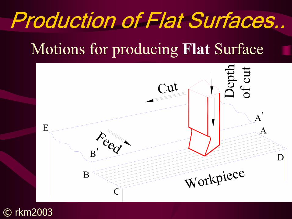
Production of Flat Surfaces..Production of Flat Surfaces..Production of Flat Surfaces..Production of Flat Surfaces..Motions for producing Flat Surface
A
D
Feed
A'
Cut
E
B
'B
CWorkpiece
Dep
tho
f cu
t
© rkm2003
Reciprocating Machine Reciprocating Machine Reciprocating Machine Reciprocating Machine ToolsToolsToolsTools
• different from rotary machine tools
• A single-point tool moves linearly
relative to the work part
•Shaper�Shaping�tool moves
•Planer�Planing�workpiece moves
•Slotter

© rkm2003
Shaper/Shaper/Shaper/Shaper/Shaping MachineRam
ToolWorkpiece
Vise
Base
v
Table
f or d
Tool head
d or f
Column

© rkm2003
Shaper/Shaper/Shaper/Shaper/Shaping MachineMain PartsBase
Column – drive, support & guide ram
Table – hold & feed workpiece
Ram – tool head, clapper box
Types of Shaping M/c
• Horizontal Shaper
• Vertical Shaper (Slotting M/c)

© rkm2003
Shaping OperationShaping OperationShaping OperationShaping OperationCutting action and functioning of
clapper box in a shaper
Tool cleared
from machined
surface
Clapper box
Workpiece
(b) Return stroke
Lifted
clapper
box
(a) Forward/Cutting stroke

© rkm2003
Shaping Operation..Shaping Operation..Shaping Operation..Shaping Operation..

© rkm2003
Shaping Operation ..Shaping Operation ..Shaping Operation ..Shaping Operation ..Machining of inclined surface on shaping
machine
θ
Tool
θ
Workpiece
Inclined
machined
surface
Tool head & slide
(axis parallel to
machined surface)Clapper box
(axis away from
toolhead)
Tool holder
located at a
convenient angle
Depth of cut
Movement
of the slide
for feed

© rkm2003
Operating Conditions in a Operating Conditions in a Operating Conditions in a Operating Conditions in a Shaping MachineShaping MachineShaping MachineShaping Machine
m/min
where
N = the number of double strokes or cycles
of the ram per min (one double or full stroke
= one cutting and one return stroke)
L = Length of the ram stroke in mm
m = return stroke time/cutting stroke time
1000
)1( mLNvspeedcutting
+=

© rkm2003
Operating Conditions in a Operating Conditions in a Operating Conditions in a Operating Conditions in a
Shaping MachineShaping MachineShaping MachineShaping Machine ..
Length of Stroke L = Lj + 2 c
Workpiece
c c Clearance
Return Stroke
Cutting Stroke
Length of stroke L
Lj

© rkm2003
Operating Conditions in a Operating Conditions in a Operating Conditions in a Operating Conditions in a Shaping Machine ..Shaping Machine ..Shaping Machine ..Shaping Machine ..
Feed f
• Feed f is the relative motion of the
workpiece in a direction perpendicular
to the axis of reciprocation of the ram
• Feed is expressed in mm/double stroke
or simply mm/stroke because no cutting
is done in return stroke

© rkm2003
Operating Conditions in a Operating Conditions in a Operating Conditions in a Operating Conditions in a Shaping Machine ..Shaping Machine ..Shaping Machine ..Shaping Machine ..
Depth of Cut d
• Depth of cut d is the thickness of the
material removed in one cut, in mm
• Depth of cut may be given by the tool
head slide or by lifting the table

© rkm2003
Machining TimeMachining TimeMachining TimeMachining Time
Width cut in 1 stroke = fTotal width = wNo. of strokes to m/c total surface = w/fStrokes/mm = NTime for machining surface is
t = w/(f N) min
f mmw mm L mm

© rkm2003
Machining TimeMachining TimeMachining TimeMachining Time
Machining time
min1000
)1(
fv
mwL
Nf
wt
+==
From cutting speed
)1(
1000
1000
)1(
mL
vN
mLNv
+=⇒
+=
Time for machining w x L surface
minNf
wt =

© rkm2003
Material Removal RateMaterial Removal RateMaterial Removal RateMaterial Removal Rate• Material removal rate (MRR)
MRR = f d L N(1+m) mm3/min
where d is depth of cut in mmf is feed in mm/stroke;N is strokes/min L is length of stroke in mmm is ratio of return stroke time to cutting stroke time

© rkm2003
PlanerPlanerPlanerPlaner

© rkm2003
Planer/Planing MachinePlaner/Planing MachinePlaner/Planing MachinePlaner/Planing Machine
Tool headBed
Tool head
Tool heads
Housing
Reciprocating
table
Guideways

© rkm2003
Types of Planing MachinesTypes of Planing MachinesTypes of Planing MachinesTypes of Planing Machines
• Open Side Planer
• Double Housing Planer
• Edge planer
• Universal planer,
• Pit type planer

© rkm2003
Operating Conditions in a Operating Conditions in a Operating Conditions in a Operating Conditions in a PlanerPlanerPlanerPlaner
• Operating conditions in planer are similar to Shaping Machine
Cutting Speed: Workpiece reciprocatescutting time=return time
Cutting Tool: Multiple cutting tools cut simultaneously
Job: Large size or multiple workpieces

© rkm2003
SSSSiiiizzzzeeee ooooffff SSSShhhhaaaappppiiiinnnngggg aaaannnndddd PPPPllllaaaannnniiiinnnngggg MachinesMachinesMachinesMachines
• Largest Size of Workpiece that can
be Machined
L x w x h

© rkm2003
DDDDiiiiffffffffeeeerrrreeeennnncccceeee bbbbeeeettttwwwweeeeeeeennnn SSSShhhhaaaappppeeeerrrr aaaannnndddd PlanerPlanerPlanerPlaner
• Size of Workpiece• Movement of Tool and Workpiece• Construction • Cutting and Return Speeds• Number of toolheads

© rkm2003
Slotting
Ram
Tool
Base
Tool
holder
Column
Table
Typical Job
Slotter/Slotting Machine
Slot made
by slotting

© rkm2003
Example 7.1Find the machining time required for machining
the surface 600 × 800 mm, on a shaping machine. Assume, cutting speed as 8 m/min. The return to cutting time ratio is 1:4, and the feed is 2 mm/double stroke. The clearance at each end is 70 mm.
• SolutionLj = 600 mm, w = 800 mm, v = 8 m/min,
m = ¼, f = 2 mm/stroke, c = 70 mm

© rkm2003
Example 7.1 ..• Given clearance at each end: c=75 mm
• length of stroke: L = 600 + 2×70 = 740 mm
nstrokes/mi65.8)1(
1000
1000
)1(=
+=⇒
+=
mL
vN
mLNv
min25.46==Nf
wt
Assume 8.65 strokes/min available
• Machining time for 800 mm width

© rkm2003
Example 7.1 ..
• Alternately:
min25.46
281000
)25.01(800740
1000
)1(
=
××
+××=
+=
fv
mwLt
Assumptions:Assumptions:Assumptions:Assumptions:
N?N?N?N?

© rkm2003
Examples• Example 7.2: Estimate the time required to
machine a cast iron surface 250 mm long and 150 mm wide on a shaper with cutting-to-return ratio of 3/2. Use a cutting speed of 21 m/min, a feed of 2 mm/stroke and a clearance of 25 mm. The available ram strokes on the shaper are: 28, 40, 60 and 90 strokes/min. Also, determine MRR assuming depth of cut as 4 mm.
• Solution• Given data: Lj = 250 mm, f = 2 mm/double
stroke, w = 150 mm, • c = 25 mm, v = 21 m/ m/min, d = 4 mm• The cutting-to-return ratio of 3/2 gives m = 2/3

© rkm2003
Examples
• Given clearance is 25 mm, hence,• L = 250 + 2 × 25 = 300 mm.• We know that (Equation (1))• SPEED v = NL(1+m)/ 1000 m/min• From the above equation, we find
number of double strokes N per minute required as
• N = 42 strokes/min

© rkm2003
Examples• Nearest available ram strokes is 40
strokes/min. Since calculated value is more than 40, this is chosen. Normally, we should not exceed the specified cutting speed, as it will affect the tool life adversely. Hence, select N = 40 strokes/min.
• With a chosen value of N, we cannot use Equation (5) for time calculation. Hence, substituting all the values in Equation (6), we get
• t = 150 / (40×2)• = 1.88 minutes