Embed Size (px)
Citation preview

1
ENG
LISH
INSTRUCTION MANUAL
DOUBLE INSULATION
WARNING: For your personal safety, READ and UNDERSTAND before using. SAVE THESE INSTRUCTIONS FOR FUTURE REFERENCE.
Power PlanerKP0810 KP0810C
007638

2
ENGLISH
SPECIFICATIONS Model KP0810 KP0810C
Planing width 82 mm Planing depth 4 mm
Shiplapping depth 25 mm No load speed (min-1) 16,000 12,000
Overall length 290 mm Net weight 3.2 kg 3.3 kg
Safety class /II • Due to our continuing programme of research and development, the specifications herein are subject to change without notice. • Note: Specifications may differ from country to country.
END201-3
Symbols The following show the symbols used for the equipment. Be sure that you understand their meaning before use.
・ Read instruction manual. ・ DOUBLE INSULATION ・ Only for EU countries
Do not dispose of electric equipment together with household waste material! In observance of European Directive 2002/96/EC on waste electric and electronic equipment and its implementation in accordance with national law, electric equipment that have reached the end of their life must be collected separately and returned to an environmentally compatible recycling facility.
ENE001-1
Intended use The tool is intended for planing wood.
ENF002-1
Power supply The tool should be connected only to a power supply of the same voltage as indicated on the nameplate, and can only be operated on single-phase AC supply. They are double-insulated in accordance with European Standard and can, therefore, also be used from sockets without earth wire. For Model KP0810
ENG005-2
For European countries only Noise and Vibration The typical A-weighted noise levels are sound pressure level: 87 dB (A) sound power level: 98 dB (A) Uncertainty: 3 dB(A)
Wear ear protection. The typical weighted root mean square acceleration
value is not more than 2.5 m/s2. These values have been obtained according to EN60745. For Model KP0810C
ENG003-2
For European countries only Noise and Vibration The typical A-weighted sound pressure level is 84 dB (A). Uncertainty is 3 dB(A). The noise level under working may exceed 85 dB (A).
Wear ear protection. The typical weighted root mean square acceleration value is not more than 2.5 m/s2. These values have been obtained according to EN60745.
ENH101-7
EC-DECLARATION OF CONFORMITY Model; KP0810/ KP0810C We declare under our sole responsibility that this product is in compliance with the following standards of standardized documents; EN60745, EN55014, EN61000 in accordance with Council Directives, 2004/108/EC, 98/37/EC.
CE2006
000230
Tomoyasu Kato Director
Responsible Manufacturer: Makita Corporation 3-11-8, Sumiyoshi-cho, Anjo, Aichi, JAPAN Authorized Representative in Europe: Makita International Europe Ltd. Michigan Drive, Tongwell, Milton Keynes, Bucks MK15 8JD, ENGLAND

3
GEA001-3
GENERAL SAFETY RULES WARNING! Read all instructions. Failure to follow all instructions listed below may result in electric shock, fire and/or serious injury. The term "power tool" in all of the warnings listed below refers to your mains-operated (corded) power tool or battery-operated (cordless) power tool.
SAVE THESE INSTRUCTIONS. Work area safety 1. Keep work area clean and well lit. Cluttered and
dark areas invite accidents. 2. Do not operate power tools in explosive
atmospheres, such as in the presence of flammable liquids, gases or dust. Power tools create sparks which may ignite the dust or fumes.
3. Keep children and bystanders away while operating a power tool. Distractions can cause you to lose control.
Electrical Safety 4. Power tool plugs must match the outlet. Never
modify the plug in any way. Do not use any adapter plugs with earthed (grounded) power tools. Unmodified plugs and matching outlets will reduce risk of electric shock.
5. Avoid body contact with earthed or grounded surfaces such as pipes, radiators, ranges and refrigerators. There is an increased risk of electric shock if your body is earthed or grounded.
6. Do not expose power tools to rain or wet conditions. Water entering a power tool will increase the risk of electric shock.
7. Do not abuse the cord. Never use the cord for carrying, pulling or unplugging the power tool. Keep cord away from heat, oil, sharp edges or moving parts. Damaged or entangled cords increase the risk of electric shock.
8. When operating a power tool outdoors, use an extension cord suitable for outdoor use. Use of a cord suitable for outdoor use reduces the risk of electric shock.
Personal Safety 9. Stay alert, watch what you are doing and use
common sense when operating a power tool. Do not use a power tool while you are tired or under the influence of drugs, alcohol or medication. A moment of inattention while operating power tools may result in serious personal injury.
10. Use safety equipment. Always wear eye protection. Safety equipment such as dust mask, non-skid safety shoes, hard hat, or hearing protection used for appropriate conditions will
reduce personal injuries. 11. Avoid accidental starting. Ensure the switch is
in the off-position before plugging in. Carrying power tools with your finger on the switch or plugging in power tools that have the switch on invites accidents.
12. Remove any adjusting key or wrench before turning the power tool on. A wrench or a key left attached to a rotating part of the power tool may result in personal injury.
13. Do not overreach. Keep proper footing and balance at all times. This enables better control of the power tool in unexpected situations.
14. Dress properly. Do not wear loose clothing or jewellery. Keep your hair, clothing, and gloves away from moving parts. Loose clothes, jewellery or long hair can be caught in moving parts.
15. If devices are provided for the connection of dust extraction and collection facilities, ensure these are connected and properly used. Use of these devices can reduce dust-related hazards.
Power tool use and care 16. Do not force the power tool. Use the correct
power tool for your application. The correct power tool will do the job better and safer at the rate for which it was designed.
17. Do not use the power tool if the switch does not turn it on and off. Any power tool that cannot be controlled with the switch is dangerous and must be repaired.
18. Disconnect the plug from the power source and/or the battery pack from the power tool before making any adjustments, changing accessories, or storing power tools. Such preventive safety measures reduce the risk of starting the power tool accidentally.
19. Store idle power tools out of the reach of children and do not allow persons unfamiliar with the power tool or these instructions to operate the power tool. Power tools are dangerous in the hands of untrained users.
20. Maintain power tools. Check for misalignment or binding of moving parts, breakage of parts and any other condition that may affect the power tools operation. If damaged, have the power tool repaired before use. Many accidents are caused by poorly maintained power tools.
21. Keep cutting tools sharp and clean. Properly maintained cutting tools with sharp cutting edges are less likely to bind and are easier to control.
22. Use the power tool, accessories and tool bits etc. in accordance with these instructions and in the manner intended for the particular type

4
of power tool, taking into account the working conditions and the work to be performed. Use of the power tool for operations different from those intended could result in a hazardous situation.
SERVICE 23. Have your power tool serviced by a qualified
repair person using only identical replacement parts. This will ensure that the safety of the power tool is maintained.
24. Follow instruction for lubricating and changing accessories.
25. Keep handles dry, clean and free from oil and grease.
GEB010-2
SPECIFIC SAFETY RULES DO NOT let comfort or familiarity with product (gained from repeated use) replace strict adherence to planer safety rules. If you use this tool unsafely or incorrectly, you can suffer serious personal injury. 1. Wait for the cutter to stop before setting the
tool down. An exposed cutter may engage the surface leading to possible loss of control and serious injury.
2. Use clamps or another practical way to secure and support the workpiece to a stable platform. Holding the work by hand or against your body leaves it unstable and may lead to loss of control.
3. Rags, cloth, cord, string and the like should never be left around the work area.
4. Avoid cutting nails. Inspect for and remove all nails from the workpiece before operation.
5. Use only sharp blades. Handle the blades very carefully.
6. Be sure the blade installation bolts are securely tightened before operation.
7. Hold the tool firmly with both hands. 8. Keep hands away from rotating parts. 9. Before using the tool on an actual workpiece,
let it run for a while. Watch for vibration or wobbling that could indicate poor installation or a poorly balanced blade.
10. Make sure the blade is not contacting the workpiece before the switch is turned on.
11. Wait until the blade attains full speed before cutting.
12. Always switch off and wait for the blades to come to a complete stop before any adjusting.
13. Never stick your finger into the chip chute. Chute may jam when cutting damp wood. Clean out chips with a stick.
14. Do not leave the tool running. Operate the tool only when hand-held.
15. Always change both blades or covers on the
drum, otherwise the resulting imbalance will cause vibration and shorten tool life.
16. Use only Makita blades specified in this manual.
17. Always use the correct dust mask/respirator for the material and application you are working with.
SAVE THESE INSTRUCTIONS.
WARNING: MISUSE or failure to follow the safety rules stated in this instruction manual may cause serious personal injury.
FUNCTIONAL DESCRIPTION
CAUTION: • Always be sure that the tool is switched off and
unplugged before adjusting or checking function on the tool.
Adjusting depth of cut
1
2
007639
Depth of cut may be adjusted by simply turning the knob on the front of the tool so that the pointer points the desired depth of cut.
Switch action
CAUTION: • Before plugging in the tool, always check to see
that the switch trigger actuates properly and returns to the "OFF" position when released.
12
007640
1. Lock button / Lock-off button
2. Switch trigger
1. Knob 2. Pointer

5
For tool with lock button To start the tool, simply pull the switch trigger. Release the switch trigger to stop. For continuous operation, pull the switch trigger and then push in the lock button from either side. To stop the tool from the locked position, pull the switch trigger fully, then release it. For tool with lock-off button To prevent the switch trigger from being accidentally pulled, a lock-off button is provided. To start the tool, depress the lock-off button from either side and pull the switch trigger. Release the switch trigger to stop.
Electronic function For Model KP0810C only The tool equipped with electronic function are easy to operate because of the following features. Constant speed control Electronic speed control for obtaining constant speed. Possible to get fine finish, because the rotating speed is kept constant even under load condition. Soft start Soft-start feature minimizes start-up shock, and makes the tool start smoothly.
Foot
1 2 3 007688
After a cutting operation, raise the back side of the tool and a foot comes under the level of the rear base. This prevents the tool blades to be damaged.
ASSEMBLY
CAUTION: • Always be sure that the tool is switched off and
unplugged before carrying out any work on the tool.
Removing or installing planer blades
CAUTION: • Tighten the blade installation bolts carefully when
attaching the blades to the tool. A loose installation bolt can be dangerous. Always check to see they are tightened securely.
• Handle the blades very carefully. Use gloves or rags to protect your fingers or hands when removing or installing the blades.
• Use only the Makita wrench provided to remove or install the blades. Failure to do so may result in overtightening or insufficient tightening of the installation bolts. This could cause an injury.
For tool with standard planer blades
1
007641
1
2345
002555
1234567
8
9 002556
To remove the blades on the drum, unscrew the installation bolts with the socket wrench. The drum cover comes off together with the blades. To install the blades, first clean out all chips or foreign matter adhering to the drum or blades. Use blades of the same dimensions and weight, or drum oscillation/vibration will result, causing poor planing action and, eventually, tool breakdown. Place the blade on the gauge base so that the blade edge is perfectly flush with the inside edge of the gauge plate. Place the adjusting plate on the blade, then simply press in the heel of the adjusting plate flush with the back side of the gauge base and tighten two screws on the adjusting plate. Now slip the heel of the adjusting
1. Inside edge of gauge plate
2. Blade edge 3. Planer blade 4. Adjusting plate 5. Screws 6. Heel 7. Back side of
gauge base 8. Gauge plate 9. Gauge base
1. Bolt 2. Drum 3. Planer blade 4. Drum plate 5. Adjusting plate
1. Socket wrench
1. Planer blade 2. Rear base 3. Foot

6
plate into the drum groove, then fit the drum cover on it. Tighten all the installation bolts evenly and alternately with the socket wrench. For tool with mini planer blades 1. Remove the existing blade, if the tool has been in
use, carefully clean the drum surfaces and the drum cover. To remove the blades on the drum, unscrew the three installation bolts with the socket wrench. The drum cover comes off together with the blades.
1
007641
2. To install the blades, loosely attach the adjusting
plate to the set plate with the pan head screws and set the mini planer blade on the gauge base so that the cutting edge of the blade is perfectly flush with the inside flank of the gauge plate.
1
23
4
5
678910
002565
3. Set the adjusting plate/set plate on the gauge
base so that the planer blade locating lugs on the set plate rest in the mini planer blade groove, then press in the heel of the adjusting plate flush with the back side of the gauge base and tighten the
pan head screws. 4. It is important that the blade sits flush with the
inside flank of the gauge plate, the planer blade locating lugs sit in the blade groove and the heel of the adjusting plate is flush with the back side of the gauge base. Check this alignment carefully to ensure uniform cutting.
5. Slip the heel of the adjusting plate into the groove of the drum.
6. Set the drum cover over the adjusting plate/set plate and screw in the three hex flange head bolts so that a gap exists between the drum and the set plate to slide the mini planer blade into position. The blade will be positioned by the planer blade locating lugs on the set plate.
1
2
34
5
6
002566
7. The blade's lengthwise adjustment will need to be
manually positioned so that the blade ends are clear and equidistant from the housing on one side and the metal bracket on the other.
8. Tighten the three hex flange head bolts (with the socket wrench provided) and rotate the drum to check clearances between the blade ends and the tool body.
9. Check the three hex flange head bolts for final tightness.
10. Repeat procedures 1 - 9 for other blade.
For the correct planer blade setting Your planing surface will end up rough and uneven, unless the blade is set properly and securely. The blade must be mounted so that the cutting edge is absolutely level, that is, parallel to the surface of the rear base. Refer to some examples below for proper and improper settings.
1. Mini planer blade
2. Groove 3. Set plate 4. Hex. flange
head bolt 5. Drum plate 6. Drum
1. Pan head screw2. Adjusting plate3. Planer blade
locating lugs 4. Gauge plate 5. Heel of
adjusting plate6. Set plate 7. Inside flank of
gauge plate 8. Gauge base 9. Back side of
gauge base 10. Mini planer
blade
1. Socket wrench
7
(A)(B)
(B)
(A)(B)
(A)
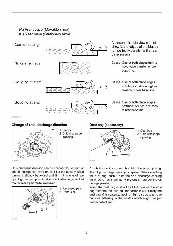
(A) Front base (Movable shoe)
(B) Rear base (Stationary shoe)
Correct setting
Nicks in surface
Gouging at start
Gouging at end
Although this side view cannot
show it, the edges of the blades
run perfectly parallel to the rear
base surface.
Cause: One or both blades fails to
have edge parallel to rear
base line.
Cause: One or both blade edges
fails to protrude enough in
relation to rear base line.
Cause: One or both blade edges
protrudes too far in relation
to rear base line.
EN0004-1
Change of chip discharge direction
1
2
007643
Chip discharge direction can be changed to the right or left. To change the direction, pull out the stopper while turning it slightly backward and fit in it in one of two openings on the opposite side of chip discharge so that the recessed part fits to protrusion.
12
007801
Dust bag (accessory)
1 2
007687
Attach the dust bag onto the chip discharge opening. The chip discharge opening is tapered. When attaching the dust bag, push it onto the chip discharge opening firmly as far as it will go to prevent it from coming off during operation. When the dust bag is about half full, remove the dust bag from the tool and pull the fastener out. Empty the dust bag of its contents, tapping it lightly so as to remove particles adhering to the insides which might hamper further collection.
1. Dust bag 2. Chip discharge
opening
1. Recessed part2. Protrusion
1. Stopper 2. Chip discharge
opening

8
1
007802
NOTE: • If you connect a Makita vacuum cleaner to this tool,
more efficient and cleaner operations can be performed.
Connecting a vacuum cleaner
1
007644
When you wish to perform clean planing operation, connect a Makita vacuum cleaner to your tool. Then connect a hose of the vacuum cleaner to the chip discharge opening as shown in the figures.
Elbow (optional accessory)
1 007645
Use of elbow allows change of chip discharge direction to perform cleaner work. Install the elbow (optional accessory) on the tool by just slipping on it. To remove it, just pull it out.
OPERATION Hold the tool firmly with one hand on the knob and the other hand on the switch handle when performing the tool. Planing operation
1 2
007646
First, rest the tool front base flat upon the workpiece surface without the blades making any contact. Switch on and wait until the blades attain full speed. Then move the tool gently forward. Apply pressure on the front of tool at the start of planing, and at the back at the end of planing. Planing will be easier if you incline the workpiece in stationary fashion, so that you can plane somewhat downhill. The speed and depth of cut determine the kind of finish. The power planer keeps cutting at a speed that will not result in jamming by chips. For rough cutting, the depth of cut can be increased, while for a good finish you should reduce the depth of cut and advance the tool more slowly.
Shiplapping (Rabbeting)
002580
To make a stepped cut as shown in the figure, use the edge fence (guide rule). Adjust the shiplapping depth using a depth guide (accessory). Draw a cutting line on the workpiece. Insert the edge fence into the hole in the front of the tool. Align the blade edge with the cutting line.
1. Start 2. End
1. Elbow
1. Vacuum cleaner
1. Fastener

9
1
23
007647
Install the edge fence on the tool and secure it with the washer and thumb screw (A). Loosen the thumb screw (B) and adjust the edge fence until it comes in contact with the side of the workpiece. Then tighten the thumb screw (B) securely.
1
23
007648
When planing, move the tool with the edge fence flush with the side of the workpiece. Otherwise uneven planing may result.
CAUTION: • The blade edge should be made to protrude
outside slightly (0.2 mm - 0.4 mm) for shiplapping.
0.2 - 0.4mm
007649
You may wish to add to the length of the fence by attaching an extra piece of wood. Convenient holes are provided in the fence for this purpose, and also for attaching an extension guide (optional accessory).
007714
Chamfering
003634
To make a chamfering cut as shown in the figure, align one of three "V" grooves in the front base with the edge of the workpiece and plane it.
123
007650
Use of chamfering rule (optional accessory) assures more tool stability when shiplapping.
1 2
007653
To install the chamfering rule, remove two screws on both sides of the front of the tool and set the depth of cut to 4 mm. And then install it on the front base of the tool and secure it the screws as shown in the figure. When doing a great amount of chamfering, place an edge of chamfering rule so that it contacts workpiece
1. Chamfering rule 2. Screws
1. V groove (medium amount of chamfering)
2. V groove (small amount of chamfering)
3. V groove (great amount of chamfering)
1. Screw (A) 2. Screw (B) 3. Edge fence
1. Blade edge 2. Cutting line 3. Depth guide

10
and make many passes of planing as shown in the figure.
b a 1
007828
MAINTENANCE
CAUTION: • Always be sure that the tool is switched off and
unplugged before attempting to perform inspection or maintenance.
Sharpening the planer blades For standard blades only Always keep your blades sharp for the best performance possible. Use the sharpening holder to remove nicks and produce a fine edge.
1
002588
First, loosen the two wing nuts on the holder and insert the blades (A) and (B), so that they contact the sides (C) and (D). Then tighten the wing nuts.
1
2
3 4
5
002589
Immerse the dressing stone in water for 2 or 3 minutes before sharpening. Hold the holder so that the both blades contact the dressing stone for simultaneous sharpening at the same angle.
002590
Replacing carbon brushes
1
001145
Remove and check the carbon brushes regularly. Replace when they wear down to the limit mark. Keep the carbon brushes clean and free to slip in the holders. Both carbon brushes should be replaced at the same time. Use only identical carbon brushes. Use a screwdriver to remove the rear cover.
1 2
007651
Take out the worn carbon brushes, insert the new ones and secure the rear cover.
1
007652
To maintain product SAFETY and RELIABILITY, repairs, any other maintenance or adjustment should be performed by Makita Authorized Service Centers,
1. Carbon brushes
1. Screwdriver 2. Rear cover
1. Limit mark
1. Wing nut 2. Blade (A) 3. Blade (B) 4. Side (D) 5. Side (C)
1. Sharpening holder
1. Edge of chamfering rule

11
always using Makita replacement parts.
ACCESSORIES
CAUTION: • These accessories or attachments are
recommended for use with your Makita tool specified in this manual. The use of any other accessories or attachments might present a risk of injury to persons. Only use accessory or attachment for its stated purpose.
If you need any assistance for more details regarding these accessories, ask your local Makita Service Center.
• High-speed steel Planer blade • Tungsten-carbide Planer blade (For longer blade
life) • Mini planer blade • Sharpening holder assembly • Blade gauge • Set plate set • Edge fence (Guide rule) • Dressing stone • Dust bag assembly • Elbow • Socket wrench • Chamfering rule assembly

12
Makita Corporation Anjo, Aichi, Japan
884693B225