Embed Size (px)
Citation preview
Shaping light beams in nonlinear processes using structured light and patterned crystals
SIVAN TRAJTENEBRG-MILLS* AND ADY ARIE
School of Electrical Engineering, Faculty of Engineering, Tel-Aviv University, Tel-Aviv 69978, Israel *[email protected]
Abstract: Shaping light in second order nonlinear interaction is a compact way of controlling both shape and frequency of the output, a desirable trait for many different applications such as optical communication, particle manipulation, microscopy, spectroscopy, and quantum information. The use of patterned nonlinear crystals, combining holographic methods with electric field poling, has proven a useful way to create arbitrary one- and two-dimensional shapes, as well as beams that follow curved trajectories. Using structured light as an input beam has also been shown to produce light with special properties, such as vortex beams carrying orbital angular momentum, curved Airy beams, and others. We review the latest advances in the field. © 2017 Optical Society of America
OCIS codes: (190.0190) Nonlinear optics; (190.4400) Nonlinear optics, materials; (090.0090) Holography; (230.5298) Photonic crystals.
References and links
1. H. He, M. E. J. Friese, N. R. Heckenberg, and H. Rubinsztein-Dunlop, “Direct observation of transfer of angular momentum to absorptive particles from a laser beam with a phase singularity,” Phys. Rev. Lett. 75(5), 826–829 (1995).
2. T. Vettenburg, H. I. C. Dalgarno, J. Nylk, C. Coll-Lladó, D. E. K. Ferrier, T. Čižmár, F. J. Gunn-Moore, and K. Dholakia, “Light-sheet microscopy using an Airy beam,” Nat. Methods 11(5), 541–544 (2014).
3. A. Mair, A. Vaziri, G. Weihs, and A. Zeilinger, “Entanglement of the orbital angular momentum states of photons,” Nature 412(6844), 313–316 (2001).
4. J. Wang, J.-Y. Yang, I. M. Fazal, N. Ahmed, Y. Yan, H. Huang, Y. Ren, Y. Yue, S. Dolinar, M. Tur, and A. E. Willner, “Terabit free-space data transmission employing orbital angular momentum multiplexing,” Nat. Photonics 6(7), 488–496 (2012).
5. A. Libster-Hershko, S. Trajtenberg-Mills, and A. Arie, “Dynamic control of light beams in second harmonic generation,” Opt. Lett. 40(9), 1944–1947 (2015).
6. G. Imeshev, M. Proctor, and M. M. Fejer, “Lateral patterning of nonlinear frequency conversion with transversely varying quasi-phase-matching gratings,” Opt. Lett. 23(9), 673–675 (1998).
7. J. R. Kurz, A. M. Schober, D. S. Hum, A. J. Saltzman, and M. M. Fejer, “Nonlinear physical optics with transversely patterned quasi-phase-matching gratings,” in Summaries of Papers Presented at the Lasers and Electro-Optics. CLEO ’02. Technical Diges (Opt. Soc. America, 2002), pp. 377–378.
8. T. Ellenbogen, N. Voloch-Bloch, A. Ganany-Padowicz, and A. Arie, “Nonlinear generation and manipulation of Airy beams,” Nat. Photonics 3(7), 395–398 (2009).
9. A. Shapira, I. Juwiler, and A. Arie, “Nonlinear computer-generated holograms,” Opt. Lett. 36(15), 3015–3017 (2011).
10. X.-H. Hong, B. Yang, C. Zhang, Y.-Q. Qin, and Y.-Y. Zhu, “Nonlinear Volume Holography for Wave-Front Engineering,” Phys. Rev. Lett. 113(16), 163902 (2014).
11. C.-Y. Lu, D. E. Browne, T. Yang, and J.-W. Pan, “Demonstration of a compiled version of Shor’s quantum factoring algorithm using photonic qubits,” Phys. Rev. Lett. 99(25), 250504 (2007).
12. B. Yang, X.-H. Hong, R.-E. Lu, Y.-Y. Yue, C. Zhang, Y.-Q. Qin, and Y.-Y. Zhu, “2D wave-front shaping in optical superlattices using nonlinear volume holography,” Opt. Lett. 41(13), 2927–2929 (2016).
13. A. Shapira, A. Libster, Y. Lilach, and A. Arie, “Functional facets for nonlinear crystals,” Opt. Commun. 300, 244–248 (2013).
14. S. Lightman, R. Gvishi, G. Hurvitz, and A. Arie, “Shaping of light beams by 3D direct laser writing on facets of nonlinear crystals,” Opt. Lett. 40(19), 4460–4463 (2015).
15. A. Shapira, L. Naor, and A. Arie, “Nonlinear optical holograms for spatial and spectral shaping of light waves,” Sci. Bull. 60(16), 1403–1415 (2015).
16. N. V. Bloch, K. Shemer, A. Shapira, R. Shiloh, I. Juwiler, and A. Arie, “Twisting light by nonlinear photonic crystals,” Phys. Rev. Lett. 108(23), 233902 (2012).
17. K. Shemer, N. Voloch-Bloch, A. Shapira, A. Libster, I. Juwiler, and A. Arie, “Azimuthal and radial shaping of
Vol. 7, No. 8 | 1 Aug 2017 | OPTICAL MATERIALS EXPRESS 2928
#295042 https://doi.org/10.1364/OME.7.002928 Journal © 2017 Received 2 May 2017; revised 16 Jun 2017; accepted 19 Jun 2017; published 20 Jul 2017

vortex beams generated in twisted nonlinear photonic crystals,” Opt. Lett. 38(24), 5470–5473 (2013). 18. D. Liu, Y. Zhang, J. Wen, Z. Chen, D. Wei, X. Hu, G. Zhao, S. N. Zhu, and M. Xiao, “Diffraction interference
induced superfocusing in nonlinear Talbot effect,” Sci. Rep. 4(1), 6134 (2015). 19. R. Remez and A. Arie, “Super-narrow frequency conversion,” Optica 2(5), 472 (2015). 20. S. Trajtenberg-Mills, I. Juwiler, and A. Arie, “On-axis shaping of second-harmonic beams,” Laser Photonics
Rev. 9(6), L40–L44 (2015). 21. I. Dolev, T. Ellenbogen, and A. Arie, “Switching the acceleration direction of Airy beams by a nonlinear optical
process,” Opt. Lett. 35(10), 1581–1583 (2010). 22. S. Trajtenberg-Mills, I. Juwiler, and A. Arie, “Generation of second-harmonic beams with switchable curved
trajectories,” Optica 4(1), 153 (2017). 23. R. W. Boyd, Nonlinear Optics (Academic Press, 2008). 24. M. Yamada, N. Nada, M. Saitoh, and K. Watanabe, “First-order quasi-phase matched LiNbO3 waveguide
periodically poled by applying an external field for efficient blue second-harmonic generation,” Appl. Phys. Lett. 62(5), 435–436 (1993).
25. D. Gabor, “A New Microscopic Principle,” Nature 161(4098), 777–778 (1948). 26. B. E. A. Saleh and M. C. Teich, Fundamentals of Photonics (Wiley, 2013). 27. B. R. Brown and A. W. Lohmann, “Complex spatial filtering with binary masks,” Appl. Opt. 5(6), 967–969
(1966). 28. J. J. Burch, “A computer algorithm for the synthesis of spatial frequency filters,” Proc. IEEE 55(4), 599–601
(1967). 29. W. H. Lee, “Binary computer-generated holograms,” Appl. Opt. 18(21), 3661–3669 (1979). 30. M. A. Bandres, I. Kaminer, M. Mills, B. M. Rodríguez-Lara, E. Greenfield, M. Segev, and D. N.
Christodoulides, “Accelerating optical beams,” Opt. Photonics News 24(6), 30 (2013). 31. D. N. Christodoulides, “Optical trapping: Riding along an Airy beam,” Nat. Photonics 2(11), 652–653 (2008). 32. J. Baumgartl, M. Mazilu, and K. Dholakia, “Optically mediated particle clearing using Airy wavepackets,” Nat.
Photonics 2(11), 675–678 (2008). 33. A. Mathis, L. Froehly, L. Furfaro, M. Jacquot, J. M. Dudley, and F. Courvoisier, “Direct machining of curved
trenches in silicon with femtosecond accelerating beams,” J. Eur. Opt. Soc. 8, 13019 (2013). 34. M. V. Berry and N. L. Balazs, “Nonspeading wave packets,” Am. J. Phys. 47(3), 264–267 (1979). 35. E. Greenfield, M. Segev, W. Walasik, and O. Raz, “Accelerating light beams along arbitrary convex
trajectories,” Phys. Rev. Lett. 106(21), 213902 (2011). 36. L. Froehly, F. Courvoisier, A. Mathis, M. Jacquot, L. Furfaro, R. Giust, P. A. Lacourt, and J. M. Dudley,
“Arbitrary accelerating micron-scale caustic beams in two and three dimensions,” Opt. Express 19(17), 16455–16465 (2011).
37. E. Greenfield, M. Segev, W. Walasik, and O. Raz, “Accelerating light beams along arbitrary convex trajectories,” Phys. Rev. Lett. 106(21), 213902 (2011).
38. I. Epstein and A. Arie, “Arbitrary bending plasmonic light waves,” Phys. Rev. Lett. 112(2), 023903 (2014). 39. S. Zhao, Y. Hu, J. Lu, X. Qiu, J. Cheng, and I. Burnett, “Delivering Sound Energy along an Arbitrary Convex
Trajectory,” Sci. Rep. 4(1), 6628 (2015). 40. D. S. Hum and M. M. Fejer, “Quasi-phasematching,” C. R. Phys. 8(2), 180–198 (2007). 41. M. Houe and P. D. Townsend, “An introduction to methods of periodic poling for second-harmonic generation,”
J. Phys. D Appl. Phys. 28(9), 1747–1763 (1995). 42. Y. Glickman, E. Winebrand, A. Arie, and G. Rosenman, “Electron-beam-induced domain poling in LiNbO 3 for
two-dimensional nonlinear frequency conversion,” Appl. Phys. Lett. 88, 011103 (2006). 43. X. Chen, P. Karpinski, V. Shvedov, A. Boes, A. Mitchell, W. Krolikowski, and Y. Sheng, “Quasi-phase
matching via femtosecond laser-induced domain inversion in lithium niobate waveguides,” Opt. Lett. 41(11), 2410–2413 (2016).
44. L. A. Eyres, P. J. Tourreau, T. J. Pinguet, C. B. Ebert, J. S. Harris, M. M. Fejer, L. Becouarn, B. Gerard, and E. Lallier, “All-epitaxial fabrication of thick, orientation-patterned GaAs films for nonlinear optical frequency conversion,” Appl. Phys. Lett. 79(7), 904–906 (2001).
45. K. Fradkin-Kashi, A. Arie, P. Urenski, and G. Rosenman, “Mid-infrared difference-frequency generation in periodically poled KTiOAsO4 and application to gas sensing,” Opt. Lett. 25(10), 743–745 (2000).
46. K. Fradkin-Kashi, A. Arie, P. Urenski, and G. Rosenman, “Characterization of optical and nonlinear properties of periodically-poled RbTiOAsO4 in the mid-infrared range via difference-frequency generation,” Appl. Phys. B 71(2), 251–255 (2000).
47. D. A. Bryan, R. Gerson, and H. E. Tomaschke, “Increased optical damage resistance in lithium niobate,” Appl. Phys. Lett. 44(9), 847–849 (1984).
48. M. Katz, R. K. Route, D. S. Hum, K. R. Parameswaran, G. D. Miller, and M. M. Fejer, “Vapor-transport equilibrated near-stoichiometric lithium tantalate for frequency-conversion applications,” Opt. Lett. 29(15), 1775–1777 (2004).
49. Y. Furukawa, K. Kitamura, E. Suzuki, and K. Niwa, “Stoichiometric LiTaO3 single crystal growth by double crucible Czochralski method using automatic powder supply system,” J. Cryst. Growth 197(4), 889–895 (1999).
50. F. Nitanda, Y. Furukawa, S. Makio, M. Sato, and K. Ito, “Increased optical damage resistance and transparency in MgO-doped LiTaO3 single crystals,” Jpn. J. Appl. Phys. 34(1), 1546–1549 (1995).
51. Y. Furukawa, K. Kitamura, S. Takekawa, K. Niwa, and H. Hatano, “Stoichiometric Mg:LiNbO3 as an effective
Vol. 7, No. 8 | 1 Aug 2017 | OPTICAL MATERIALS EXPRESS 2929
material for nonlinear optics,” Opt. Lett. 23(24), 1892–1894 (1998). 52. A. Leshem, G. Meshulam, G. Porat, and A. Arie, “Adiabatic second-harmonic generation,” Opt. Lett. 41(6),
1229–1232 (2016). 53. A. Zukauskas, G. Strömqvist, V. Pasiskevicius, F. Laurell, M. Fokine, and C. Canalias, “Fabrication of
submicrometer quasi-phase-matched devices in KTP and RKTP [Invited],” Opt. Mater. Express 1(7), 1319 (2011).
54. A. Zukauskas, V. Pasiskevicius, and C. Canalias, “Quasi-periodic self-assembled sub-micrometer ferroelectric bulk domain gratings in Rb-doped KTiOPO4,” Appl. Phys. Lett. 103(25), 252905 (2013).
55. C. Canalias and V. Pasiskevicius, “Mirrorless optical parametric oscillator,” Nat. Photonics 1(8), 459–462 (2007).
56. H. Ishizuki and T. Taira, “Half-joule output optical-parametric oscillation by using 10-mm-thick periodically poled Mg-doped congruent LiNbO3,” Opt. Express 20(18), 20002–20010 (2012).
57. S. Trajtenberg-Mills, I. Juwiler, and A. Arie, “Generation of second harmonic beams with switchable curved trajectories,” Optica 4, 153—156 (2016).
58. C. R. Phillips, B. W. Mayer, L. Gallmann, and U. Keller, “Frequency-domain nonlinear optics in two-dimensionally patterned quasi-phase-matching media,” Opt. Express 24(14), 15940–15953 (2016).
59. N. G. R. Broderick, G. W. Ross, H. L. Offerhaus, D. J. Richardson, and D. C. Hanna, “Hexagonally Poled Lithium Niobate: A Two-Dimensional Nonlinear Photonic Crystal,” Phys. Rev. Lett. 84(19), 4345–4348 (2000).
60. A. Shapira, R. Shiloh, I. Juwiler, and A. Arie, “Two-dimensional nonlinear beam shaping,” Opt. Lett. 37(11), 2136–2138 (2012).
61. B. Yang, X.-H. Hong, R.-E. Lu, Y.-Y. Yue, C. Zhang, Y.-Q. Qin, and Y.-Y. Zhu, “Nonlinear Image Formation by Optical Superlattices,” https://arxiv.org/abs/1511.07121 (2015).
62. A. Shapira, I. Juwiler, and A. Arie, “Tunable nonlinear beam shaping by non-collinear interactions,” Laser Photonics Rev. 7(4), L25–L29 (2013).
63. A. Shapira, I. Juwiler, and A. Arie, “Tunable nonlinear beam shaping by non-collinear interactions,” Laser Photonics Rev. 7(4), L25–L29 (2013).
64. B. Yang, X.-H. Hong, R.-E. Lu, Y.-Y. Yue, C. Zhang, Y.-Q. Qin, and Y.-Y. Zhu, “2D wave-front shaping in optical superlattices using nonlinear volume holography,” Opt. Lett. 41(13), 2927–2929 (2016).
65. A. Christ, A. Fedrizzi, H. Hübel, T. Jennewein, and C. Silberhorn, Single-Photon Generation and Detection - Physics and Applications, Experimental Methods in the Physical Sciences (Elsevier, 2013), Vol. 45.
66. P. G. Kwiat, K. Mattle, H. Weinfurter, A. Zeilinger, A. V. Sergienko, and Y. Shih, “New high-intensity source of polarization-entangled photon pairs,” Phys. Rev. Lett. 75(24), 4337–4341 (1995).
67. G. Weihs, T. Jennewein, C. Simon, H. Weinfurter, and A. Zeilinger, “Violation of Bell’s Inequality under Strict Einstein Locality Conditions,” Phys. Rev. Lett. 81(23), 5039–5043 (1998).
68. H. Takesue and K. Inoue, “Generation of polarization-entangled photon pairs and violation of Bell’s inequality using spontaneous four-wave mixing in a fiber loop,” Phys. Rev. A 70(3), 031802 (2004).
69. T. Jennewein, C. Simon, G. Weihs, H. Weinfurter, and A. Zeilinger, “Quantum cryptography with entangled photons,” Phys. Rev. Lett. 84(20), 4729–4732 (2000).
70. A. Z. D. Bouwmeester, J. W. Pan, K. Mattle, M. Eibl, H. Weinfurter, and A. Zeilinger, “Experimental Quantum Teleportation,” Nature 390(6660), 575–579 (1997).
71. T. B. Pittman, B. C. Jacobs, and J. D. Franson, “Heralding single photons from pulsed parametric down-conversion,” Opt. Commun. 246(4-6), 545–550 (2005).
72. J. P. Torres, A. Alexandrescu, S. Carrasco, and L. Torner, “Quasi-phase-matching engineering for spatial control of entangled two-photon states,” Opt. Lett. 29(4), 376–378 (2004).
73. H. Jin, P. Xu, X. W. Luo, H. Y. Leng, Y. X. Gong, W. J. Yu, M. L. Zhong, G. Zhao, and S. N. Zhu, “Compact engineering of path-entangled sources from a monolithic quadratic nonlinear photonic crystal,” Phys. Rev. Lett. 111(2), 023603 (2013).
74. E. Megidish, A. Halevy, H. S. Eisenberg, A. Ganany-Padowicz, N. Habshoosh, and A. Arie, “Compact 2D nonlinear photonic crystal source of beamlike path entangled photons,” Opt. Express 21(6), 6689–6696 (2013).
75. H. Y. Leng, X. Q. Yu, Y. X. Gong, P. Xu, Z. D. Xie, H. Jin, C. Zhang, and S. N. Zhu, “On-chip steering of entangled photons in nonlinear photonic crystals,” Nat. Commun. 2, 429 (2011).
76. Y. Ming, J. Tang, Z. Chen, F. Xu, L. Zhang, and Y. Lu, “Generation of N00N State With Orbital Angular Momentum in a Twisted Nonlinear Photonic Crystal,” IEEE J. Sel. Top. Quantum Electron. 21(3), 225–230 (2015).
77. L. L. Lu, P. Xu, M. L. Zhong, Y. F. Bai, and S. N. Zhu, “Orbital angular momentum entanglement via fork-poling nonlinear photonic crystals,” Opt. Express 23(2), 1203–1212 (2015).
78. M. V. Berry, “Stable and unstable Airy-related caustics and beams,” J. Opt. 19(5), 055601 (2017). 79. G. A. Siviloglou, J. Broky, A. Dogariu, and D. N. Christodoulides, “Observation of accelerating Airy beams,”
Phys. Rev. Lett. 99(21), 213901 (2007). 80. I. Dolev, T. Ellenbogen, N. Voloch-Bloch, and A. Arie, “Control of free space propagation of Airy beams
generated by quadratic nonlinear photonic crystals,” Appl. Phys. Lett. 95, 201112 (2009). 81. L. Allen, M. W. Beijersbergen, R. J. C. Spreeuw, and J. P. Woerdman, “Orbital angular momentum of light and
the transformation of Laguerre-Gaussian laser modes,” Phys. Rev. A 45(11), 8185–8189 (1992). 82. K. Dholakia, N. B. Simpson, M. J. Padgett, and L. Allen, “Second-harmonic generation and the orbital angular
momentum of light,” Phys. Rev. A 54, R3742 (2009).
Vol. 7, No. 8 | 1 Aug 2017 | OPTICAL MATERIALS EXPRESS 2930
83. S.-M. Li, L.-J. Kong, Z.-C. Ren, Y. Li, C. Tu, and H.-T. Wang, “Managing orbital angular momentum in second-harmonic generation,” Phys. Rev. A 88(3), 05801 (2013).
84. W. T. Buono, L. F. C. Moraes, J. A. O. Huguenin, C. E. R. Souza, and A. Z. Khoury, “Arbitrary orbital angular momentum addition in second harmonic generation,” New J. Phys. 16(9), 093041 (2014).
85. H. Liu, J. Li, X. Zhao, Y. Zheng, and X. Chen, “Nonlinear Raman-Nath second harmonic generation with structured fundamental wave,” Opt. Express 24(14), 15666–15671 (2016).
86. I. Kaminer, M. Segev, and D. N. Christodoulides, “Self-Accelerating Self-Trapped Optical Beams,” Phys. Rev. Lett. 106(21), 213903 (2011).
87. I. Dolev, I. Kaminer, A. Shapira, M. Segev, and A. Arie, “Experimental Observation of Self-Accelerating Beams in Quadratic Nonlinear Media,” Phys. Rev. Lett. 108(11), 113903 (2012).
88. I. Dolev and A. Arie, “Three wave mixing of airy beams in a quadratic nonlinear photonic crystals,” Appl. Phys. Lett. 97, 171102 (2010).
89. I. Dolev, A. Libster, and A. Arie, “Self-accelerating parabolic beams in quadratic nonlinear media,” Appl. Phys. Lett. 101, 101109 (2012).
90. M. A. Bandres, “Accelerating parabolic beams,” Opt. Lett. 33(15), 1678–1680 (2008). 91. T. B. Pittman, D. V. Strekalov, D. N. Klyshko, M. H. Rubin, A. V. Sergienko, and Y. H. Shih, “Two-photon
geometric optics,” Phys. Rev. A 53(4), 2804–2815 (1996). 92. C. H. Monken, P. H. S. Ribeiro, and S. Pádua, “Transfer of angular spectrum and image formation in
spontaneous parametric down-conversion,” Phys. Rev. A 57(4), 3123–3126 (1998). 93. J. A. Rodrigo, T. Alieva, E. Abramochkin, and I. Castro, “Shaping of light beams along curves in three
dimensions,” Opt. Express 21(18), 20544–20555 (2013). 94. E. R. Shanblatt and D. G. Grier, “Extended and knotted optical traps in three dimensions,” Opt. Express 19(7),
5833–5838 (2011). 95. R. Piestun and J. Shamir, “Synthesis of three-dimensional light fields and applications,” Proc. IEEE 90(2), 222–
244 (2002). 96. T. Latychevskaia and H.-W. Fink, “Inverted Gabor holography principle for tailoring arbitrary shaped three-
dimensional beams,” Sci. Rep. 6(1), 26312 (2016).
1. Introduction
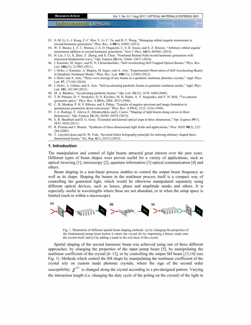
The manipulation and control of light beams attracted great interest over the past years. Different types of beam shapes were proven useful for a variety of applications, such as optical tweezing [1], microscopy [2], quantum information [3] optical communication [4] and others.
Beam shaping in a non-linear process enables to control the output beam frequency as well as its shape. Shaping the beams in the nonlinear process itself is a compact way of controlling the generated light, which would be otherwise manipulated separately using different optical devices, such as lenses, phase and amplitude masks and others. It is especially useful in wavelengths where these are not abundant, or in when the setup space is limited (such as within a microscope).
Fig. 1. Illustration of different spatial beam shaping methods: (a) by changing the properties of the fundamental pump beam before it enters the crystal (b) by imprinting a binary mask onto the crystal itself, and (c) by adding a mask to the exit facet of the crystal.
Spatial shaping of the second harmonic beam was achieved using one of three different approaches: by changing the properties of the input pump beam [5], by manipulating the nonlinear coefficient of the crystal [6–12], or by controlling the output SH beam [13,14] (see Fig. 1). Methods which control the SH shape by manipulating the nonlinear coefficient of the crystal rely on custom made photonic crystals, where the sign of the second order
susceptibility (2)χ is changed along the crystal according to a pre-designed pattern. Varying
the interaction length (i.e. changing the duty cycle of the poling on the crystal) of the light in
Vol. 7, No. 8 | 1 Aug 2017 | OPTICAL MATERIALS EXPRESS 2931
the crystal enables control of the amplitude of the crystal while the phase can be controlled through transverse-dependent phase terms [15].
Latest works on the subject have shown a large variety of beam shapes, including self-similar beams [9], beams carrying orbital angular momentum (OAM) [16,17], as well as manifestation of special effects such as the Talbot effect [18] or super-oscillation [19]. Recent achievements show generation of arbitrary shapes in either one transverse dimension [20] or in both transverse dimensions [12]. In addition to transverse beams shaping, control of the beams along the propagation axis was also achieved. Self-accelerating beams such as the Airy beam was demonstrated [8,21], and lately also beams with arbitrary caustic trajectories have been generated [22].
2. Theoretical background
Second order nonlinear interaction
In second order nonlinear optics, the polarization (dipole moment per unit volume) induced upon a material by an electric field, depends on the square of the input field. This nonlinear polarization acts as a source for light at new frequencies, different from that of the input beam. The nonlinear material couples between the fields involved in the process, causing them to exchange energy between them. Second order nonlinear processes must conserve energy and momentum. Energy conservation dictates that the generated signal’s frequency must be the sum or difference of the two input waves (or a second harmonic of one of them). In a similar fashion, momentum conservation, of phase matching dictates conditions on the wave vectors of the interacting waves and on the crystal quasi momentum.
The propagation through the nonlinear media is generally described by Maxwell’s equations. For time harmonic waves and under the slowly varying envelope approximation, these equations can be reduced to a set of coupled wave equations (CWE), coupling between the three waves interacting in the material. For the process of second harmonic generation (SHG), a degenerate case where the signal and pump have the same frequency, and the generated idler has a doubled frequency of ω2 = 2ω1, these equations are [23]:
(2) 2*1
1 22
(2) 222 2
2 2 2
22
2
i kzT
i kzT
AA ik A A e
x c
AA ik A e
x c
ωω ω ω
ωω ω
χ ω
χ ω
Δ
Δ
∂∇ + = −
∂∂
∇ + = −∂
(1)
Where x is the propagation axis (x is chosen as the propagation axis throughout this paper in order to be consistent with the popular propagation along the crystalline x axis), z and y are the transverse coordinates, 2 2
T z y∇ = ∂ + ∂ is the transverse Laplacian, Aω and A2ω are the input
pump and generated SH amplitudes, c is the speed of light and (2)χ is the second order
susceptibility. ( )n
kcω
ω ω⋅= , 2
2 (2 )nk
cωω ω⋅= are the wave vectors for the pump and SH, n
is the refractive index and Δk is a vector denoting the phase mismatch between the waves:
22Δ = −ω ωk k k . Due to material dispersion, this value is nonzero in most cases, causing the
process to be very inefficient. This can be overcome by using angle tuning in birefringent materials in order to achieve the proper conditions for phase matching. Another popular method for increasing the efficiency of the process is by modulating the nonlinear coefficient by imposing a periodic function on it along the propagation direction x, a process called quasi phase matching (QPM). The nonlinear susceptibility can be expanded to its Fourier components:
Vol. 7, No. 8 | 1 Aug 2017 | OPTICAL MATERIALS EXPRESS 2932
(2) (2)( ) | | exp( )m mm
x G ik xχ χ∞
=−∞
= − (2)
It is now clear that by choosing ( )2 ( )xχ to be a periodic function and taking it’s leading
order in the Fourier expansion, an extra moment of mik is added to Δi kxe . By choosing the
period of the periodic function imposed on ( )2χ to be 2
Δk
πΛ = , the phase mismatch is
compensated for, since 1
2Δ
Λk k
π− = = − . Practically, in the existing methods for modulating
the nonlinear coefficient, only binary modulation is possible nowadays [24].
Holography
Holography is a method for recording and recovering desired wave front information. The interference between a desired wave and a reference wave is recorded [25] on the hologram. The desired wavefront can later be reconstructed by shining the reference wave on this hologram. The method relies on a physical attribute of waves, which states that the complete information arriving from an object is stored in the phase and amplitude of a two dimensional wavefront at any point [26]. There are no limitations on the objects used as long as they are larger than the wavelength.
Computer generated holograms (CGH) [27] are holograms where the interference pattern is numerically calculated instead of physically recording an interference pattern of the object and reference beams. The light intensity distribution of the interference between the reference
wave ER (assumed here to be a plane wave) and the desired wave ( ) ( )( ), cos ,D DE A z y z yφ=
2 2 2( , ) | | | | | | 2 cosR D R D R DI x y E E E A E A φ= + = + + (3)
where φ is the phase difference between the two waves. The last term is the interference
term, which can be calculated if the phase and amplitude of ED and ER are known. The calculation can be performed to give a continuous range of values [28], though for many applications a binary scheme is preferred [29]. In both cases, both the phase and amplitude of the desired wave have to be known in order to calculate the appropriate hologram. Since phase information is lost in intensity patterns of an object (which are what is conventionally measured using cameras and so), this is not always trivial. CGH’s offer a wide range of possibilities, as they do not rely on availability and quality of the interference recording materials, and since they do not require the actual object – they can generate 3-D images of nonexistent objects.
In standard linear holography, the reconstructed wave must be separated from the reference wave. This is easily achieved by off-axis Fourier holography, i.e. imposing a carrier frequency upon the hologram, causing the reconstructed beam to split into multiple diffraction orders in the far field, whose angle mθ can be easily calculated from the carrier
frequency by cam rrierm fλθ = , where m is the diffraction order and lambda is the wavelength.
The desired wave can be then separated easily from other diffraction terms by spatial filtering. Since the hologram is reconstructed in the far field, and using the Fourier transform relation for wave propagation between the near and far field [26] implies that the encoded phase and amplitude of the desired wave should be that of the wave’s Fourier transform.
Binary CGH’s require some algorithm for clipping the continuous function, while preserving the amplitude and phase information of the interference pattern in Eq. (3). One way of clipping is simply by taking sign{ cosφ } from Eq. (3), a concept known as volume
holography. A more sophisticated algorithm proposed by Lee [29] uses a biased function for hard clipping the desired function:
Vol. 7, No. 8 | 1 Aug 2017 | OPTICAL MATERIALS EXPRESS 2933
( ) ( )1, cos (2 ) ( , ) cos ( , ) 0
( , )0,
carrierf y z y q z yt z y
else
π φ π+ − ≥=
(4)
where t(z,y) is the transmission as a function of the transverse coordinates z and y, fcarrier is the carrier frequency, ( ) ( ), exp( , )A z y i z yφ is the Fourier transform of the desired wave, and
( ) ( )( )1,
, sinA z y
q z yπ
−= . The desired wave is reconstructed in the first diffraction order.
Caustic shaping
As mentioned above, beams which follow a curved trajectory along their propagation have been a subject of great interest over the past years, both because of the counterintuitive propagation of beams which supposedly “self-accelerate” [30] without the existence of forces along the trajectory, as well as their promise for application in optical manipulation [31,32], material processing [33] and light-sheet microscopy [2].
These waves do not, in fact, break physical laws. The bending is a manifestation of a constructive interference pattern along the curve. Ideal theoretical solutions, such as the Airy beam [34] carry infinite energy and have an infinite number of lobes, while in reality the truncated, finite energy beams undergo diffraction and abandon their curved trajectory after some distance. Having understood this, one can create beams that follow arbitrary curved trajectories over a limited propagation distance by tailoring constructive interference of waves along the trajectory. Every point along the desired trajectory c(x) in the propagation axis x must have a tangent line with a slope at an angle θ which builds it constructively, so that
( )tan
dc x
dxθ= . This can be parametrized using
( ) ( )c x ydc x
dx x
− = , where y is the
transverse axis. The phase of the wave at the input plane x = 0, φ(y), can be derived
geometrically [35,36] by using ( )
sind y
kdy
ϕθ= :
2
( ) '( )
1 ( '( ))
d y kc x
dy c x
ϕ =+
(5)
where k is the wave number and ( ) ( )dc xc x
dx′ = . This calculation has been used in order to
generate arbitrary caustic curves in linear (free-space) optics [36,37], plasmonic waves [38] and acoustic [39] waves.
3. Fabrication of poled crystals
The ability to modulate the second order susceptibility is highly desirable in nonlinear optics not only because it enables a considerable improvement in the efficiency of the process through QPM, but also because it provides the required flexibility for spatial and spectral shaping of the output beam. There are number of methods to modulate the nonlinear coefficient. In ferroelectric materials, this can be done by inversion of the ferroelectric domains. Several methods were successfully employed, including ion exchange [40,41], ion beam irradiation [42], femtosecond laser induced domain inversion [43] and electric field poling [24].QPM can be also realized in other materials, for example in semiconductors such as GaAs by epitaxial growth of orientationaly patterned crystals [44].
Vol. 7, No. 8 | 1 Aug 2017 | OPTICAL MATERIALS EXPRESS 2934
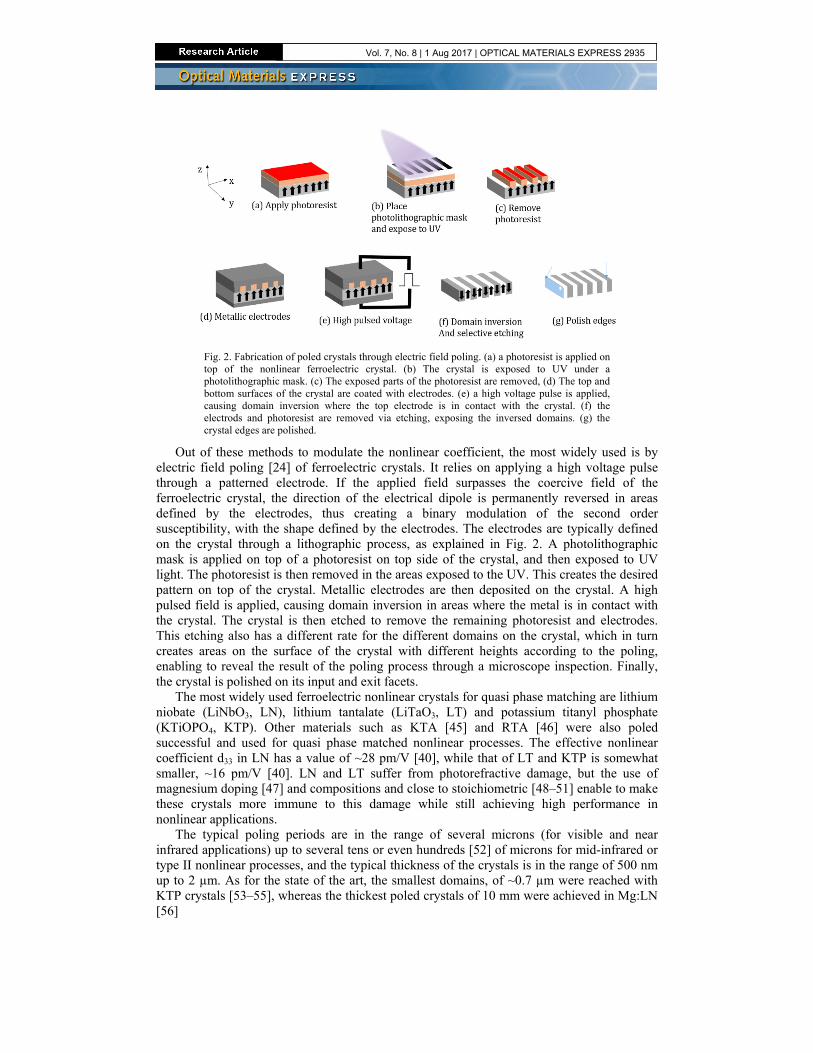
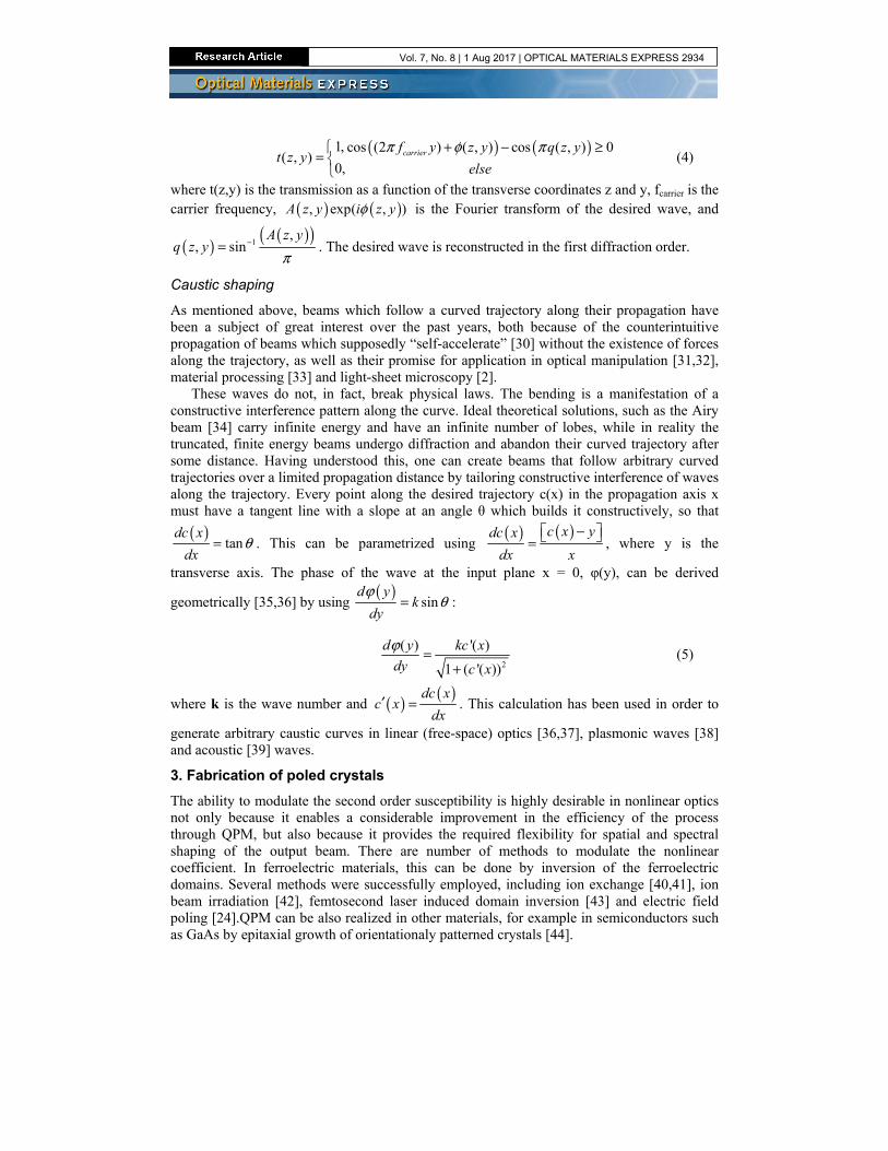
Fig. 2. Fabrication of poled crystals through electric field poling. (a) a photoresist is applied on top of the nonlinear ferroelectric crystal. (b) The crystal is exposed to UV under a photolithographic mask. (c) The exposed parts of the photoresist are removed, (d) The top and bottom surfaces of the crystal are coated with electrodes. (e) a high voltage pulse is applied, causing domain inversion where the top electrode is in contact with the crystal. (f) the electrods and photoresist are removed via etching, exposing the inversed domains. (g) the crystal edges are polished.
Out of these methods to modulate the nonlinear coefficient, the most widely used is by electric field poling [24] of ferroelectric crystals. It relies on applying a high voltage pulse through a patterned electrode. If the applied field surpasses the coercive field of the ferroelectric crystal, the direction of the electrical dipole is permanently reversed in areas defined by the electrodes, thus creating a binary modulation of the second order susceptibility, with the shape defined by the electrodes. The electrodes are typically defined on the crystal through a lithographic process, as explained in Fig. 2. A photolithographic mask is applied on top of a photoresist on top side of the crystal, and then exposed to UV light. The photoresist is then removed in the areas exposed to the UV. This creates the desired pattern on top of the crystal. Metallic electrodes are then deposited on the crystal. A high pulsed field is applied, causing domain inversion in areas where the metal is in contact with the crystal. The crystal is then etched to remove the remaining photoresist and electrodes. This etching also has a different rate for the different domains on the crystal, which in turn creates areas on the surface of the crystal with different heights according to the poling, enabling to reveal the result of the poling process through a microscope inspection. Finally, the crystal is polished on its input and exit facets.
The most widely used ferroelectric nonlinear crystals for quasi phase matching are lithium niobate (LiNbO3, LN), lithium tantalate (LiTaO3, LT) and potassium titanyl phosphate (KTiOPO4, KTP). Other materials such as KTA [45] and RTA [46] were also poled successful and used for quasi phase matched nonlinear processes. The effective nonlinear coefficient d33 in LN has a value of ~28 pm/V [40], while that of LT and KTP is somewhat smaller, ~16 pm/V [40]. LN and LT suffer from photorefractive damage, but the use of magnesium doping [47] and compositions and close to stoichiometric [48–51] enable to make these crystals more immune to this damage while still achieving high performance in nonlinear applications.
The typical poling periods are in the range of several microns (for visible and near infrared applications) up to several tens or even hundreds [52] of microns for mid-infrared or type II nonlinear processes, and the typical thickness of the crystals is in the range of 500 nm up to 2 µm. As for the state of the art, the smallest domains, of ~0.7 µm were reached with KTP crystals [53–55], whereas the thickest poled crystals of 10 mm were achieved in Mg:LN [56]
Vol. 7, No. 8 | 1 Aug 2017 | OPTICAL MATERIALS EXPRESS 2935
Fig. 3. Poling examples on 0.5-mm thick stoichiometric lithium tantalate doped with 0.5% MgO SLT after selective etching the reveals the poled structure. (a) Features having size of less than 2 µm for a custom shape of straight lines. (b) Curved domains, not normal to the crystalline x-axis, with high resolution poling, illustrating of the difficulties of poling areas with high curvature: while the relatively straight areas are successfully poled, the areas of high curvature and higher resolution did not achieve the required pattern.
Since the above mentioned nonlinear crystals are anisotropic, there is a preferred direction for poling, in which the domain boundaries are along the crystallographic Y axis. Curved domains, which are sometimes needed for nonlinear holography, are more challenging, especially when working in high resolutions. Here the materials of choice are mainly Mg:SLT [8,57] and MgO:CLN [15,58,59], whereas the highly anisotropic KTP is less suitable for this task. For curved structures, the state of the art in poling resolution is ~2 um in Mg:SLT, as shown in Fig. 3.
4. Nonlinear beam shaping with nonlinear holograms
An efficient way to shape the SH beam is by using CGH’s directly in the nonlinear process, by imprinting the desired hologram onto the second order susceptibility (2)χ . In this case, the
reference beam is the pump wave, the hologram is imprinted by modulating the second order nonlinear susceptibility, and the reconstructed wave is at the newly generated frequency, e.g. at the second harmonic of the pump beam in the case of SHG. Quasi-phase matching can be achieved, in addition to beam shaping, by choosing the carrier period to compensate for the phase mismatch. Since electric field poling offers only a change in the sign of (2)χ , only
binary CGH coding schemes can be used. Also, the available method relies on domain inversion along the entire thickness of the crystal, hence the modulation is possible along only the remaining two axis (x and y) of the crystal.
Demonstrations of shaping the SH using CGH used a variation of the algorithm proposed by Lee [29]. As an example, one dimensional transverse beam shaping along the Y axis, with a desired amplitude A(y) and phase φ (y), can be achieved by modulating the second order
susceptibility by:
(2) (2)( , ) {cos[2 ( )] cos( ( ))}QPMx y sign f x y q yχ χ π φ π= + − (6)
where Δ
2QPM
kf
π= is the carrier frequency (Δk being the phase mismatch), and
1( ) sin ( ( )) /q y A y π−= .
Two possible beam shaping configurations have been explored: a collinear configuration, as shown in Fig. 4(a)-4(b), where the input beam and the generated second harmonic beam are in the same direction, and a transverse configuration where the QPM modulation is perpendicular to the input, as shown in Fig. 4(c)-4(d). In a collinear setup, which has the advantage of high efficiency due to long interaction length, the propagation axis x is used for QPM while the transverse axis y is used for the holographic data. This enables one dimensional beam shaping. The first works [8,9] in the co-linear setup used Fourier
Vol. 7, No. 8 | 1 Aug 2017 | OPTICAL MATERIALS EXPRESS 2936
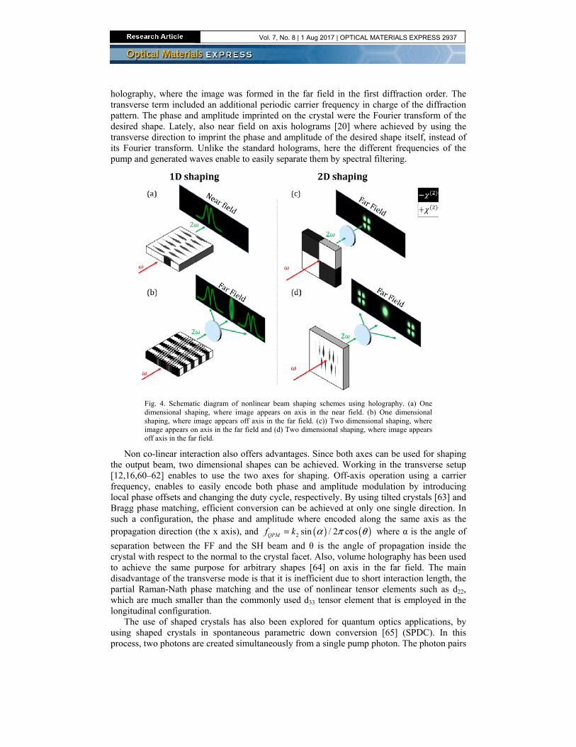
holography, where the image was formed in the far field in the first diffraction order. The transverse term included an additional periodic carrier frequency in charge of the diffraction pattern. The phase and amplitude imprinted on the crystal were the Fourier transform of the desired shape. Lately, also near field on axis holograms [20] where achieved by using the transverse direction to imprint the phase and amplitude of the desired shape itself, instead of its Fourier transform. Unlike the standard holograms, here the different frequencies of the pump and generated waves enable to easily separate them by spectral filtering.
Fig. 4. Schematic diagram of nonlinear beam shaping schemes using holography. (a) One dimensional shaping, where image appears on axis in the near field. (b) One dimensional shaping, where image appears off axis in the far field. (c)) Two dimensional shaping, where image appears on axis in the far field and (d) Two dimensional shaping, where image appears off axis in the far field.
Non co-linear interaction also offers advantages. Since both axes can be used for shaping the output beam, two dimensional shapes can be achieved. Working in the transverse setup [12,16,60–62] enables to use the two axes for shaping. Off-axis operation using a carrier frequency, enables to easily encode both phase and amplitude modulation by introducing local phase offsets and changing the duty cycle, respectively. By using tilted crystals [63] and Bragg phase matching, efficient conversion can be achieved at only one single direction. In such a configuration, the phase and amplitude where encoded along the same axis as the propagation direction (the x axis), and ( ) ( )2 sin / 2 cosQPMf k α π θ= where α is the angle of
separation between the FF and the SH beam and θ is the angle of propagation inside the crystal with respect to the normal to the crystal facet. Also, volume holography has been used to achieve the same purpose for arbitrary shapes [64] on axis in the far field. The main disadvantage of the transverse mode is that it is inefficient due to short interaction length, the partial Raman-Nath phase matching and the use of nonlinear tensor elements such as d22, which are much smaller than the commonly used d33 tensor element that is employed in the longitudinal configuration.
The use of shaped crystals has also been explored for quantum optics applications, by using shaped crystals in spontaneous parametric down conversion [65] (SPDC). In this process, two photons are created simultaneously from a single pump photon. The photon pairs
Vol. 7, No. 8 | 1 Aug 2017 | OPTICAL MATERIALS EXPRESS 2937
created are naturally entangled, constituting a bright source for entangled photons [66] for many different quantum experiments which require highly entangled particles [67–70]. Moreover, the detection of one photon heralds the presence of the other photon with high probability, making this process useful for quantum information applications that rely on heralded single photons [71]. Spatial shaping of the output through the use of shaped crystals enables to generate path- or polarization-entangled photons in a more efficient manner, having spatial shapes that can be better coupled to fibers and detectors, and enables multi-photon states. Spatial shaping of the mode function of the two-photon state output has been explored before only in some limited cases. Torres et al. [72] was the first to theoretically show how modulated crystals affect the output, and showed a few simple cases of QPM crystals with defects and a curved modulation. Crystals with a lattice shaped modulation [73–75] were also shown to be effective for tailoring the shape of the output. Crystals with a fork shaped modulation were recently studied [3,76,77] as sources for entangled photons carrying orbital angular momentum (OAM).
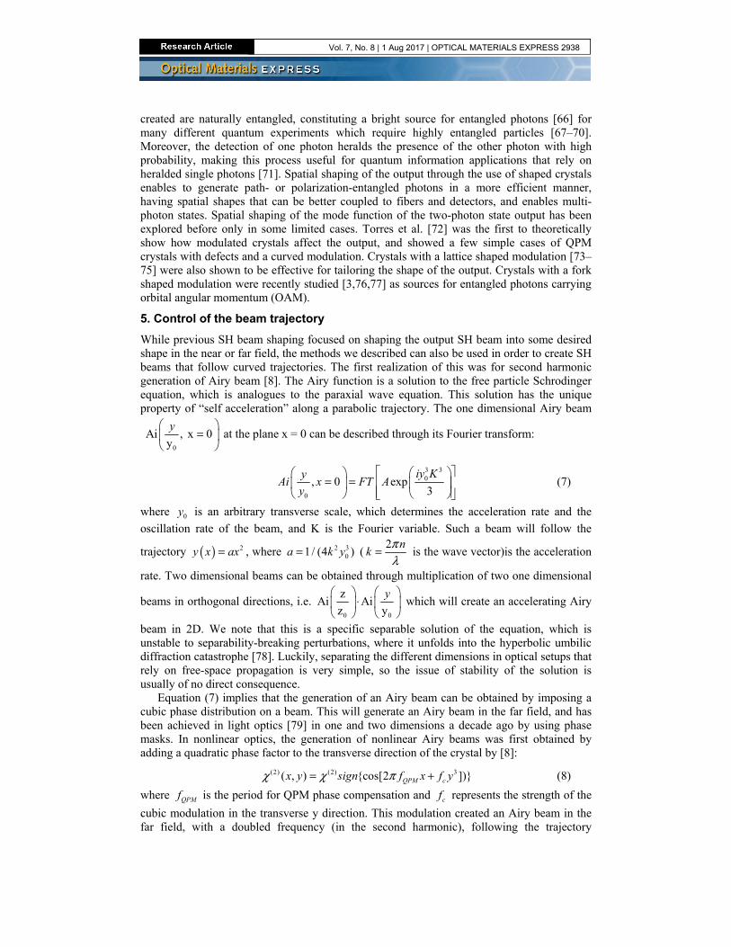
5. Control of the beam trajectory
While previous SH beam shaping focused on shaping the output SH beam into some desired shape in the near or far field, the methods we described can also be used in order to create SH beams that follow curved trajectories. The first realization of this was for second harmonic generation of Airy beam [8]. The Airy function is a solution to the free particle Schrodinger equation, which is analogues to the paraxial wave equation. This solution has the unique property of “self acceleration” along a parabolic trajectory. The one dimensional Airy beam
0
Ai , x 0y
y =
at the plane x = 0 can be described through its Fourier transform:
3 30
0
, 0 exp3
iy KyAi x FT A
y
= =
(7)
where 0y is an arbitrary transverse scale, which determines the acceleration rate and the
oscillation rate of the beam, and K is the Fourier variable. Such a beam will follow the
trajectory ( ) 2y x ax= , where 2 301/ (4 )a k y= (
2 nk
πλ
= is the wave vector)is the acceleration
rate. Two dimensional beams can be obtained through multiplication of two one dimensional
beams in orthogonal directions, i.e. 0 0
zAi Ai
z y
y ⋅
which will create an accelerating Airy
beam in 2D. We note that this is a specific separable solution of the equation, which is unstable to separability-breaking perturbations, where it unfolds into the hyperbolic umbilic diffraction catastrophe [78]. Luckily, separating the different dimensions in optical setups that rely on free-space propagation is very simple, so the issue of stability of the solution is usually of no direct consequence.
Equation (7) implies that the generation of an Airy beam can be obtained by imposing a cubic phase distribution on a beam. This will generate an Airy beam in the far field, and has been achieved in light optics [79] in one and two dimensions a decade ago by using phase masks. In nonlinear optics, the generation of nonlinear Airy beams was first obtained by adding a quadratic phase factor to the transverse direction of the crystal by [8]:
(2) (2) 3( , ) {cos[2 ])}QPM cx y sign f x f yχ χ π= + (8)
where QPMf is the period for QPM phase compensation and cf represents the strength of the
cubic modulation in the transverse y direction. This modulation created an Airy beam in the far field, with a doubled frequency (in the second harmonic), following the trajectory
Vol. 7, No. 8 | 1 Aug 2017 | OPTICAL MATERIALS EXPRESS 2938
222
1
12 c
xk fω
. Volume holography was also used in order to achieve a nonlinear Airy beam in
the near field [10]. But not only Airy beams were achieved in nonlinear interaction by modulating the crystal
phase. Arbitrary caustic trajectories were also achieved in nonlinear media [57] by using Eq. (5) to calculate the phase for arbitrary trajectories. Unlike the Airy beam, these beams are not limited to a parabolic trajectory, and are correct for the non paraxial regime as well as the paraxial regime. The phase can be obtained numerically or analytically, and the caustic is generated this time in the near field, and not in the far field like the previously achieved Airy beams.
One of the unique properties of working in nonlinear interaction as opposed to linear interaction, is the ability to change the output trajectory by changing different parameters such as the crystal temperature or input pump wavelength [21,57,80]. This is possible because phase matching is a condition which is strongly dependent on material dispersion n(λ,T) (where n is the refractive index, and is a function of the wavelength λ and temperature T). This can be achieved either by tailoring the crystal to phase match a few different processes, or by using a crystal with a single modulation but changing the nonlinear process used.
A crystal modulated according to Eq. (8), when examined for a second harmonic generation process, will create an Airy beam under the conditions 22 2QPMf k kω ωπ = − , that
will propagate along the trajectory 222
1
1 2 c
xk fω
at the far field. Consider the same modulation
for a difference frequency generation process (DFG) where the pump beam with frequency
1ω and idler wave with frequency 2ω create a third wave with frequency 3 1 2ω ω ω= − . The
same modulation can phase match such a process if 222
1
1 2 c
xk fω
−1 3 22 QPMf k k kπ = + − , and
will create an Airy beam that will propagate along the trajectory at the far field, that is, along the opposite direction. Therefore, by changing the process used from an up-conversion process to a down-conversion process switches the sign of the cubic phase modulation, and subsequently, the propagation direction of the Airy beam can be switched [21].
Another way of controlling the accelerating beam when the crystal is modulated according to Eq. (8), is by means of temperature tuning (or changing the input pump wavelength), as was experimentally shown [80]. This change causes the phase matching conditions to change, allowing for efficient non-collinear interactions, which causes the intensity peak of the beam to shift along the trajectory.
But a crystal can also be modulated in different areas with different masks. Each area can have a different polling frequency QPMf , which compensate for the phase mismatch under
different conditions of temperature (or pump wavelength). Therefore, different parts of the crystal will phase match the fundamental pump beam for these different conditions, allowing for a change in the trajectory in every section. The areas can be cascaded along the propagation trajectory as was obtained for Airy beams [8], or they can be set one aside the other, as was obtained for arbitrary caustic trajectories [57], see Fig. 5.
Vol. 7, No. 8 | 1 Aug 2017 | OPTICAL MATERIALS EXPRESS 2939
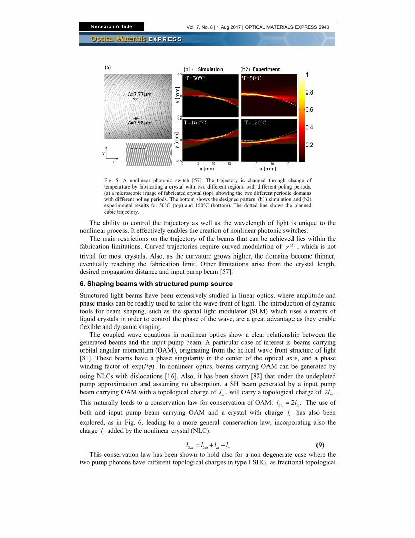
Fig. 5. A nonlinear photonic switch [57]. The trajectory is changed through change of temperature by fabricating a crystal with two different regions with different poling periods. (a) a microscopic image of fabricated crystal (top), showing the two different periodic domains with different poling periods. The bottom shows the designed pattern. (b1) simulation and (b2) experimental results for 50°C (top) and 150°C (bottom). The dotted line shows the planned cubic trajectory.
The ability to control the trajectory as well as the wavelength of light is unique to the nonlinear process. It effectively enables the creation of nonlinear photonic switches.
The main restrictions on the trajectory of the beams that can be achieved lies within the fabrication limitations. Curved trajectories require curved modulation of ( 2 )χ , which is not
trivial for most crystals. Also, as the curvature grows higher, the domains become thinner, eventually reaching the fabrication limit. Other limitations arise from the crystal length, desired propagation distance and input pump beam [57].
6. Shaping beams with structured pump source
Structured light beams have been extensively studied in linear optics, where amplitude and phase masks can be readily used to tailor the wave front of light. The introduction of dynamic tools for beam shaping, such as the spatial light modulator (SLM) which uses a matrix of liquid crystals in order to control the phase of the wave, are a great advantage as they enable flexible and dynamic shaping.
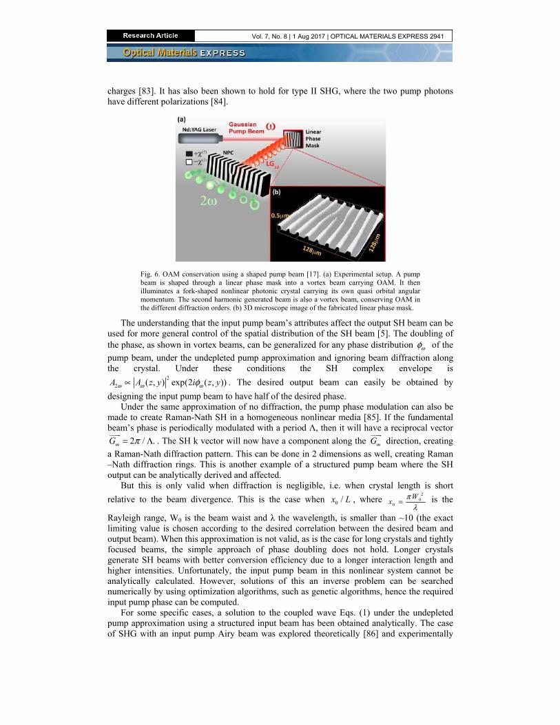
The coupled wave equations in nonlinear optics show a clear relationship between the generated beams and the input pump beam. A particular case of interest is beams carrying orbital angular momentum (OAM), originating from the helical wave front structure of light [81]. These beams have a phase singularity in the center of the optical axis, and a phase winding factor of exp( )ilφ . In nonlinear optics, beams carrying OAM can be generated by
using NLCs with dislocations [16]. Also, it has been shown [82] that under the undepleted pump approximation and assuming no absorption, a SH beam generated by a input pump beam carrying OAM with a topological charge of lω , will carry a topological charge of 2lω .
This naturally leads to a conservation law for conservation of OAM: 2 2 . l lω ω= The use of
both and input pump beam carrying OAM and a crystal with charge cl has also been
explored, as in Fig. 6, leading to a more general conservation law, incorporating also the charge cl added by the nonlinear crystal (NLC):
2 2 cl l l lω ω ω= + + (9)
This conservation law has been shown to hold also for a non degenerate case where the two pump photons have different topological charges in type I SHG, as fractional topological
Vol. 7, No. 8 | 1 Aug 2017 | OPTICAL MATERIALS EXPRESS 2940
charges [83]. It has also been shown to hold for type II SHG, where the two pump photons have different polarizations [84].
Fig. 6. OAM conservation using a shaped pump beam [17]. (a) Experimental setup. A pump beam is shaped through a linear phase mask into a vortex beam carrying OAM. It then illuminates a fork-shaped nonlinear photonic crystal carrying its own quasi orbital angular momentum. The second harmonic generated beam is also a vortex beam, conserving OAM in the different diffraction orders. (b) 3D microscope image of the fabricated linear phase mask.
The understanding that the input pump beam’s attributes affect the output SH beam can be used for more general control of the spatial distribution of the SH beam [5]. The doubling of the phase, as shown in vortex beams, can be generalized for any phase distribution ωφ of the
pump beam, under the undepleted pump approximation and ignoring beam diffraction along the crystal. Under these conditions the SH complex envelope is
2
2 ( , ) exp(2 ( , ))A A z y i z yω ω ωφ∝ . The desired output beam can easily be obtained by
designing the input pump beam to have half of the desired phase. Under the same approximation of no diffraction, the pump phase modulation can also be
made to create Raman-Nath SH in a homogeneous nonlinear media [85]. If the fundamental beam’s phase is periodically modulated with a period Λ, then it will have a reciprocal vector
2 / .mG π= Λ
. The SH k vector will now have a component along the mG
direction, creating
a Raman-Nath diffraction pattern. This can be done in 2 dimensions as well, creating Raman –Nath diffraction rings. This is another example of a structured pump beam where the SH output can be analytically derived and affected.
But this is only valid when diffraction is negligible, i.e. when crystal length is short
relative to the beam divergence. This is the case when 0 /x L , where 2
00
Wx
πλ
= is the
Rayleigh range, W0 is the beam waist and λ the wavelength, is smaller than ~10 (the exact limiting value is chosen according to the desired correlation between the desired beam and output beam). When this approximation is not valid, as is the case for long crystals and tightly focused beams, the simple approach of phase doubling does not hold. Longer crystals generate SH beams with better conversion efficiency due to a longer interaction length and higher intensities. Unfortunately, the input pump beam in this nonlinear system cannot be analytically calculated. However, solutions of this an inverse problem can be searched numerically by using optimization algorithms, such as genetic algorithms, hence the required input pump phase can be computed.
For some specific cases, a solution to the coupled wave Eqs. (1) under the undepleted pump approximation using a structured input beam has been obtained analytically. The case of SHG with an input pump Airy beam was explored theoretically [86] and experimentally
Vol. 7, No. 8 | 1 Aug 2017 | OPTICAL MATERIALS EXPRESS 2941
[87,88]. When the input pump beam is an Airy beam with 0x and kω , it can be shown that
the asymptotic solution to the coupled wave equations is also an Airy beam, but with 2/3
0 02 y y→ and 2k kω ω→ . This means that the SH beam will oscillate 22/3 faster than the
original pump beam. Under perfect phase matching, 22k kω ω= , so the acceleration of the SH
beam will be the same since ( ) ( )2 3 2 32 2/3
0 0
1 1
4 4 2 2a
k y k yω ω
= → , and both will follow the same
trajectory 2. Another case which was numerically and experimentally [89] explored is the case of
parabolic beams [90], which together with the Airy beam are the only orthogonal and complete family of explicit solutions of the two dimensional paraxial wave equation that remain diffraction free and freely accelerate during propagation. Again, as in the case of the Airy beam, it has been shown that a fundamental parabolic beam (in 1 or 2 dimensions) generates also a parabolic-like beam in the SH. As in the case of the Airy beam, the parabolic beams in the fundamental and SH frequency follow the same curved trajectory.
Using shaped beams to control the output has also been shown for quantum wave packets in SPDC. Experiments with input beams with a cubic phase [91,92], have been used to control the two-photon output state, and proven to be useful for imaging.
7. Summary
Nonlinear beam shaping enables control of the beam shape, its frequency, as well as other parameters such as orbital angular momentum and beam trajectory. The use of structured crystals or structured input light beams reduces or eliminates the need for external elements such as lenses, filters and splitters after the process, which might not readily available at the desired wavelength. The fabrication of structured nonlinear crystals by means of electric field poling has improved over the past years to give high resolutions. Applying holographic methods such as computer generated holograms or volume holography for designing these crystals has been proven effective. Both one and two dimensional shapes have been achieved with different conversion efficiencies. Shaping of the quantum wave packet in the nonlinear SPDC process using structured crystals has also been proven useful for tailoring highly entangled photons.
Using structured pump sources, instead of structuring the crystal, has also been proven useful for shaping the nonlinearly generated light. Beams with special features, such as beams following curved trajectories, beams carrying orbital angular momentum, as well as more arbitrary shapes were achieved using this method. This is a dynamic way of controlling the output, as a single crystal can be used for many different beam shapes.
Future studies in this field include the extension of the methods presented here to other types of nonlinear crystals, such as orientation-patterned GaAs crystal, as well as further developments of the coding schemes for nonlinear process, to allow full three-dimensional reconstruction of beams, as already done nowadays with linear holograms [93–96].
Funding
Israel Science Foundation (1310/13).
Acknowledgments
We thank Dr. Irit Juwiler for her insights on crystal poling.
Vol. 7, No. 8 | 1 Aug 2017 | OPTICAL MATERIALS EXPRESS 2942