Embed Size (px)
Citation preview

Revision 3 September 23, 2015
Individual chapters of the Kalsi Seals Handbook are periodically updated. To determine if
a newer revision of this chapter exists, please visit www.kalsi.com/seal-handbook.htm.
NOTICE: The information in this chapter is provided under the terms and conditions of the Offer of
Sale, Disclaimer, and other notices provided in the front matter of this handbook.
Document 3085 © 2015 Kalsi Engineering, Inc. All rights reserved.
Kalsi Seals Handbook
Chapter D14
Shaft guided compensation pistons

Shaft guided compensation pistons Chapter D14 Page 1
Search this handbook Contact Kalsi Engineering
1. Compensation piston overview
In equipment that is submerged in a high pressure environment, such as oilfield
downhole drilling tools, the lubricant must be pressure balanced to the environment to
protect the rotary seals from excessive differential pressure. In other words, the pressure
of the lubricant within a downhole tool must be balanced to the ambient downhole
pressure, to avoid creating a differential pressure across the rotary seals that is equal to
the ambient downhole pressure. Such pressure balancing can be done with various
devices, including bladders and diaphragms, but is often accomplished with an annular,
shaft guided compensation piston1.
Figure 1
Schematic of a typical oilfield sealed bearing downhole drilling mud motor
Figure 1 is a schematic of an oilfield sealed bearing mud motor. It shows the use of
two axially movable annular pistons, a “pressure compensation piston”, and a “barrier
compensation piston”. The pressure compensation piston balances the bearing lubricant
pressure to the pressure of the drilling fluid within the drillstring bore. The stroke of the
pressure compensation piston defines the lubricant reservoir for the Kalsi Seal in the
pressure compensation piston and the fixed location Kalsi Seal. The barrier compensation
piston provides a clean lubricant environment for the fixed location Kalsi Seal, and
balances that lubricant pressure to the well annulus pressure, and its stroke defines a
lubricant reservoir for the barrier seal. The barrier compensation piston also limits the
deflection of the shaft, so that the fixed location Kalsi Seal can have a relatively small
extrusion gap. (Not all sealed bearing mud motors use a barrier compensation piston.)
When the surface mud pumps are running, the drilling fluid flows down through the
drillstring, exiting into the annulus of the well through the nozzles (not shown in
1 A "compensation piston" is sometimes referred to as a "compensating piston".

Shaft guided compensation pistons Chapter D14 Page 2
Search this handbook Contact Kalsi Engineering
Figure 1) of the drill bit. The annulus pressure is substantially lower than the drillstring
bore pressure due to the pressure drop that occurs as the drilling fluid passes through the
drill bit nozzles. The fixed location Kalsi Seal has to withstand the pressure difference
between the lubricant and the annulus (the pressure drop across the bit).
A compensation piston accomplishes six important tasks in a mud motor:
1. Partitioning the lubricant from the drilling fluid environment,
2. Substantially balancing the lubricant pressure to the drilling fluid environment,
3. Accommodating lubricant thermal expansion,
4. Providing a lubricant reservoir to accommodate hydrodynamic pumping related
seal leakage,
5. Limiting the deflection and stress of the rotary shaft, and
6. Isolating the piston mounted rotary seal from the effects of shaft runout and
deflection.
Figure 2
A typical mud motor compensation piston
An oilfield mud motor compensation piston is shaft guided by a journal bearing, to minimize the compression changes experienced by the rotary seal due to lateral shaft movement. A larger clearance is provided between the piston and the housing, to accommodate lateral shaft misalignment and deflection without overloading the journal bearing or binding the piston. The extrusion gap clearance of the mud-exposed sliding and rotary seals is relatively large, to minimize wear (see Figure 8).

Shaft guided compensation pistons Chapter D14 Page 3
Search this handbook Contact Kalsi Engineering
Journal bearing and extrusion gap sizing
A typical mud motor compensation piston is shown in Figure 2. The Axially
Constrained Kalsi Seal runs on the shaft, and the sliding seal runs on the housing bore. A
journal bearing is defined on the lubricant side of the Kalsi Seal, and an extrusion gap
bore is defined on the environment side. Guidelines for designing the length and
clearance of the journal bearing are provided in Chapter D15.
The extrusion gap bore diameter should be about 0.040” (1.02 mm) larger than the
shaft diameter in order to minimize abrasion of the Kalsi Seal and the shaft. Likewise,
from an abrasion resistance standpoint one should keep the axial length of the extrusion
gap width very short. An axial extrusion gap width in the range of 0.02 to 0.04” (0.51 to
1.01 mm) is recommended. Extrusion gap considerations are discussed in Chapter D7.
Flow restrictors
Some sealed bearing mud motor assemblies incorporate mud flow restrictors with
flow bypass orifices2 to minimize the pressure differential acting across the fixed location
Kalsi Seal. Flow restrictor arrangements are particularly relevant in high temperature
wells, because the high temperature reduces the modulus and extrusion resistance of the
fixed location rotary seal.
Swab pressure
When a mud motor is lowered in a well, it displaces drilling fluid and produces swab
pressure below the drill bit3. The fluid flows up through the drill bit nozzles, through the
mud motor, and into the drillstring bore. The pressure drop across the drill bit nozzles
causes a differential pressure across the fixed location rotary seal, acting from the drilling
fluid side. This “reverse pressure” situation distorts the fixed location Kalsi Seal, making
it more prone to abrasive invasion. For this reason, a barrier seal is recommended
outboard of the fixed location Kalsi Seal. In Figure 1, the barrier seal is mounted in an
axially movable compensation piston that balances the pressure of the barrier lubricant to
the drilling fluid environment in the annulus of the well. Chapter D10 describes other,
more compact arrangements for incorporating a barrier seal outboard of a Kalsi Seal, and
balancing the pressure of the barrier lubricant to the environment.
2. Compensation piston rotary seal groove evaluation
For groove details such as surface finish, corner radii, etc., see Chapter D5. For
groove bore diameter and tolerance, see the website and Chapter D5. After sizing the
groove diameter, perform a tolerance and clearance stackup calculation using the
2 For examples of flow restrictors with bypass orifices, see expired US Patents 3,857,655 and 3,894,818.
3 For a description of swab and surge pressure, see U.S. Patent 6,220,087.

Shaft guided compensation pistons Chapter D14 Page 4
Search this handbook Contact Kalsi Engineering
equations in Chapter D5 to verify that the minimum and maximum Kalsi Seal radial
gland dimension falls within the allowable range when the piston is laterally offset to the
maximum amount permitted by the various clearances and tolerances.
3. Piston to housing fit
In an oilfield mud motor, the compensation piston OD should ordinarily establish a
relatively large clearance with the housing bore so that the piston can move laterally with
shaft deflection without overloading the journal bearing (see Figure 2). The primary
equipment bearings should react most of the shaft side load, so that the journal bearing of
the pressure compensation piston only carries part of the intermittent peak side loads.
In applications such as mud motors, where a compensation piston is sometimes
mounted in a separate housing that is threaded to the main bearing housing, the clearance
between the housing bore and the piston OD also helps to prevent outright shaft binding
related to housing to housing threaded connection misalignment. To minimize the
potential for such shaft binding, consider implementing piloting diameters between the
housings, and pay attention to shoulder squareness.
4. Compensation piston sliding and anti-rotation seals
The sliding seal serves as a sealed partition between the lubricant and the
environment. The anti-rotation seals provide additional friction to prevent piston rotation
that can otherwise occur due to seal and bearing torque and drillstring stick-slip4. The
sliding and anti-rotation seals may be any suitable type, such as O-ring energized lip seals
or O-rings. Larger cross-sections are generally preferred, because they can more easily
accommodate lateral offset between the piston and mating bore. O-ring energized lip
seals may be preferable for the sliding seal because they are immune to spiral failure5,
and because the lips define scraping edges that help to exclude the environment. The
body of an O-ring energized lip seal should be made from elastomer rather than plastic,
so the seal can accommodate large compression changes.6 The sliding seal must continue
to seal while exposed to large compression variations, and it must have excellent
4 For information on stick-slip, see SPE 145910, “Drill Pipe Measurements Provide Valuable Insight into Drill
String Dysfunctions”. Severe vibration occurs during the slip phase.
5 For more information on spiral failure and its prevention, see Leonard J. Martini's 1984 book “Practical Seal
Design”.
6 Always check for availability before specifying O-ring energized lip seals. Be aware that the clearance
recommendations provided in catalogs for O-rings and O-ring energized lip seals are typically for high pressure
service. Such clearance recommendations may not be appropriate for compensation pistons, and may lead to
binding of the piston when non-concentric conditions occur.

Shaft guided compensation pistons Chapter D14 Page 5
Search this handbook Contact Kalsi Engineering
compression set resistance and adequate initial compression. Materials with poor
compression set resistance, inadequate temperature range, low friction, or incompatibility
with environmental fluids should be avoided.
Enough anti-rotation seals must be employed to prevent piston rotation. In the
experience of Kalsi Engineering, two 0.210” (5.33 mm) 90 Shore A
O-rings prevented spinning of the piston type shown in Figure 2. The more anti-rotation
seals there are, the less likely the piston is to spin7, but the greater the pressure buildup
before the piston moves in the axial direction—which can be hard on the rotary seal from
an abrasive exclusion standpoint.
Preventing pressure locking of the sliding seals
In equipment exposed to high ambient pressure (such as oilfield downhole mud
motors), only the sliding seal can be permitted to achieve sealed relation with the housing
bore. The sealing function of the anti-rotation seals must be defeated so that the seals
cannot trap atmospheric pressure at the time of assembly, and then become pressure
locked by the high ambient downhole pressure. Pressure locking (Figure 3) puts the full
ambient downhole pressure across the seals, which tends to bind the piston and exposes
the Kalsi Seal unnecessarily high differential pressure.
Figure 3
Do not allow pressure locking of the anti-rotation seals
If the regions between the sliding and anti-rotation seals are not vented to the lubricant, the differential pressure across the outboard seals is equal to the environment pressure, because atmospheric pressure is trapped between the seals. This causes significant friction when the unit is exposed to a high pressure environment. The friction binds the piston, which in turn increases the differential pressure across the rotary seal.
7 Rotational slippage of the piston can also be related to an excessively rough shaft surface finish generating
excessive rotary seal torque.
Shaft guided compensation pistons Chapter D14 Page 6
Search this handbook Contact Kalsi Engineering
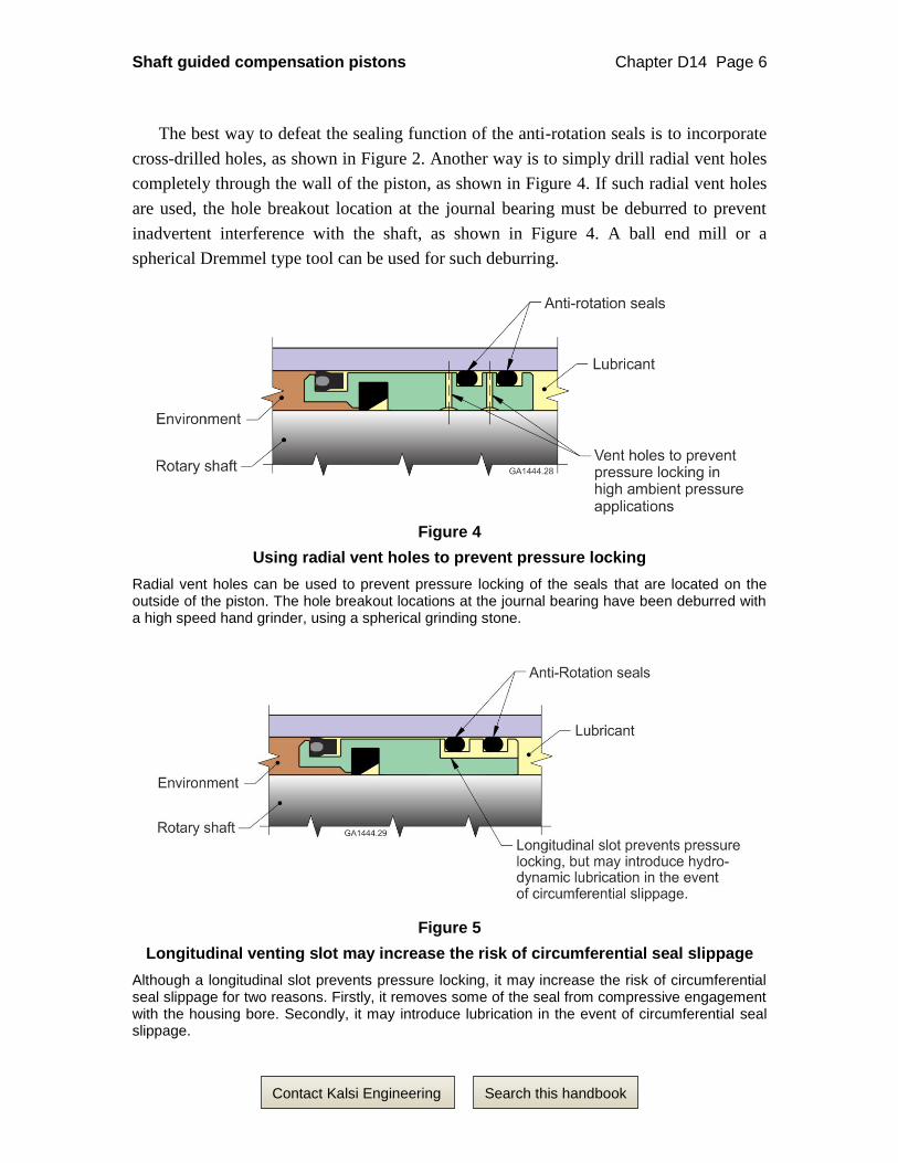
The best way to defeat the sealing function of the anti-rotation seals is to incorporate
cross-drilled holes, as shown in Figure 2. Another way is to simply drill radial vent holes
completely through the wall of the piston, as shown in Figure 4. If such radial vent holes
are used, the hole breakout location at the journal bearing must be deburred to prevent
inadvertent interference with the shaft, as shown in Figure 4. A ball end mill or a
spherical Dremmel type tool can be used for such deburring.
Figure 4
Using radial vent holes to prevent pressure locking
Radial vent holes can be used to prevent pressure locking of the seals that are located on the outside of the piston. The hole breakout locations at the journal bearing have been deburred with a high speed hand grinder, using a spherical grinding stone.
Figure 5
Longitudinal venting slot may increase the risk of circumferential seal slippage
Although a longitudinal slot prevents pressure locking, it may increase the risk of circumferential seal slippage for two reasons. Firstly, it removes some of the seal from compressive engagement with the housing bore. Secondly, it may introduce lubrication in the event of circumferential seal slippage.

Shaft guided compensation pistons Chapter D14 Page 7
Search this handbook Contact Kalsi Engineering
A less desirable way to defeat the sealing function of the anti-rotation seals is to mill
a longitudinal slot across the anti-rotation seal grooves, as shown in Figure 5. The
drawback to this method is that the longitudinal slot removes a portion of the seal from
compression, and therefore risks introducing hydrodynamic interfacial lubrication in the
event of circumferential seal slippage.
Dimensioning the groove diameters of the sliding seals
Do not make the beginner’s mistake of dimensioning the seal groove of a piston
sliding seal by its radial depth from the outer diameter of the piston. Seal grooves for
radially compressed seals are dimensioned by their diameter, not by their radial depth.
The radial groove depth that is referenced in seal catalogs is a typically a reference
dimension, and typically refers to the radial distance between the cylindrical groove
surface and the mating bore of the housing.
Evaluating sliding seal compression
The sliding seal must be large enough to accommodate worst case lateral motion
without losing compression. Perform a tolerance and clearance stackup to be sure that
sufficient compression remains under worst case conditions to retain suitable sealing
interference8. The sliding seal groove should be wide enough to accommodate the
maximum local compression that will occur if the piston is forced into contact with the
housing bore.
To determine average radial gland depth, and minimum and maximum radial depth of
the sliding seal gland assuming the piston has moved laterally into contact with the
housing bore, use the equations below (Equation variables are given in Figure 6, and in
Appendix 3).
Equation 1, Average Radial Sliding Seal Radial Gland Dimension:
2
avgavg
avg
KHW
Equation 2, Minimum Radial Sliding Seal Radial Gland Dimension:
22
maxmaxminmin
EcKJW
Equation 3, Maximum Radial Sliding Seal Radial Gland Dimension:
222
maxminmaxminmaxmax
EcJHKHW
8 Kalsi Engineering can provide O-ring groove design software to customers who are designing compensation
pistons, or other hardware that employs O-rings.

Shaft guided compensation pistons Chapter D14 Page 8
Search this handbook Contact Kalsi Engineering
Figure 6
Sliding seal groove equation variables
The variables are in diameter format. Ec is the eccentricity tolerance that can affect the position of the sliding seal groove relative to the piston outer diameter J. H is the housing bore diameter. K is the sliding seal groove diameter. W is the radial gland dimension of the sliding seal.
Understanding the size variations of sliding seals
The actual radial cross sectional dimension of a newly installed sliding seal or an anti-
rotation seal varies as a function of:
Manufacturing tolerances (available from the sliding seal manufacturer),
How much the installed seal is stretched, and
How much the installed seal is thermally expanded.
The variations in cross sectional size should be understood in order to achieve
adequate compression, and in order to allow adequate room within the seal groove to
accommodate the thermal expansion of the seal.
The effect of sliding seal stretch
Sliding seals are typically stretched diametrically when installed, to ensure that they
will fit past the housing installation chamfer without bunching and cutting. Another
reason for installed stretch is because off-the-shelf seals are typically used, and they are
only available in select sizes that may not be an exact fit for the housing bore that is being
used. At any given temperature, the volume of a seal remains constant regardless of the
amount of stretch, so as a result the cross section of the seal changes. Information on the
observed reduction in cross section as a function of stretch are available from some
sliding seal manufacturers.
Shaft guided compensation pistons Chapter D14 Page 9
Search this handbook Contact Kalsi Engineering
With O-rings, the amount of stretch related cross sectional reduction can be estimated
by:
1. Based on the diameter of the O-ring cross section, calculate the area of the
O-ring cross section using the conventional circle cross sectional area formula,
2. Multiply the cross sectional area times the mean circumference of the relaxed
O-ring to determine O-ring volume (Pappus Rule)9,
3. Determine the mean circumference of the O-ring gland,
4. Divide the O-ring volume by the mean circumference of the gland to determine
the approximate cross sectional area of the stretched O-ring, and
5. Reverse the circle cross sectional area formula to determine the diameter of the
cross section of the stretched O-ring.
The effect of sliding seal thermal expansion
The thermal expansion associated with any dimension of a sliding seal (in its relaxed,
uninstalled state) can be determined by multiplying the dimension times the linear
coefficient of thermal expansion of the elastomer.
Compression-induced O-ring length change
Ideally, to avoid potential seal damage and increased sliding friction resulting from
seal over confinement, the sliding piston to housing seal should fit in a groove that
accommodates its compressed thermally expanded MMC length, including any swelling
that may be present. If the sliding seal is installed with considerably more compression
than normally recommended by the seal manufacturer (to accommodate lateral offset, or
to increase sliding friction) the fit of the seal with the groove may have to be evaluated. If
desired, the fit of the sliding seal can be predicted with FEA.
With concentrically compressed O-rings, the compressed seal width can be calculated
by hand, with good correlation to FEA results, by using the method shown in Figure 7.
9 “Machinery's Handbook”, 23rd edition.

Shaft guided compensation pistons Chapter D14 Page 10
Search this handbook Contact Kalsi Engineering
Figure 7
Fitting an O-ring gland
The approximate MMC width of an installed O-ring can be determined using this method.
Protecting the housing bore from abrasive crushing related damage
The piston diameter that defines the environment side extrusion gap for the sliding
seal (Figure 8) should be kept smaller than the piston OD on the lubricant side of the
sliding seal so that any contact between the piston OD and the housing bore occurs in the
lubricated zone. This helps to minimize abrasive crushing in the extrusion gap that can
damage the housing bore, and can potentially impair axial motion of the piston. Housing
bore damage from the crushing of abrasives in the sliding seal extrusion gap can
compromise the function of the sliding seal.
Figure 8
Environment side extrusion gap clearance
To help to avoid crushing environmental abrasives in the environment side extrusion gap clearance (which can damage the housing bore), keep the extrusion gap clearance larger than the lubricant side piston to housing clearance.

Shaft guided compensation pistons Chapter D14 Page 11
Search this handbook Contact Kalsi Engineering
5. Construction materials
Compensation pistons can be a bearing bronze type material, or steel. Pistons may
require corrosion resistant coatings, depending on the contemplated environment. Pistons
manufactured from bearing bronze type materials will suffer increased seal groove wear
in the event of circumferential seal slippage, may suffer accelerated wear of the bore that
defines the extrusion gap if exposed to environmental abrasives, and may have
differential thermal expansion issues in large diameters. If heavy side loads are
contemplated, steel pistons should typically be lined or coated with some type of suitable
bearing material. If a coating extends to the rotary seal extrusion gap, avoid coatings that
leave ragged edges when machined, because such edges can damage the Kalsi Seal.
Potentially suitable linings include DU-type bushings and shrink fit inserts made from a
suitable bearing material, such as bearing bronze.
The mating housing bore
If exposed to a corrosive, abrasive environment, the housing bore that receives the
compensation piston should be manufactured from, or coated with, a corrosion and
abrasion resistant material that is compatible with impact loading and with the
environment. The surface finish must be smooth enough to establish a sealed relationship
with the sliding seal of the compensation piston.
6. Miscellaneous
The compensation piston should typically be located reasonably close to the primary
radial bearings of the tool to isolate it from as much shaft deflection as possible. In
oilfield mud motors, the shaft diameter should typically be kept as large as possible to
minimize load-induced deflection, shaft fatigue, and shaft breakage. Using journal
bearings to locate the shaft allows a much larger and stiffer shaft, compared to when
rolling element radial bearings are used.
In mud motors, the barrier seal in the barrier compensation piston and the high
differential pressure seal (the fixed location Kalsi Seal in Figure 1) are likely to be of
different types and possibly different materials, and are likely to employ different groove
widths even though they have the same shaft diameter. Such seals should be carefully
segregated so that they are not inadvertently installed in the wrong locations.
If desired, a high viscosity synthetic lubricant such as one having an ISO 1000
viscosity grade can be used to provide greater journal bearing load capacity10. Verify that
the lubricant is compatible with seal and piston materials; some lubricants have EP
10 Increasing lubricant viscosity will increase the hydrodynamic pumping related leak rate of the Kalsi Seal, so make
sure your reservoir size is compatible with anticipated seal leakage.
Shaft guided compensation pistons Chapter D14 Page 12
Search this handbook Contact Kalsi Engineering
additives that attack copper and silver based metals at temperatures above 210ºF
(98.9ºC).
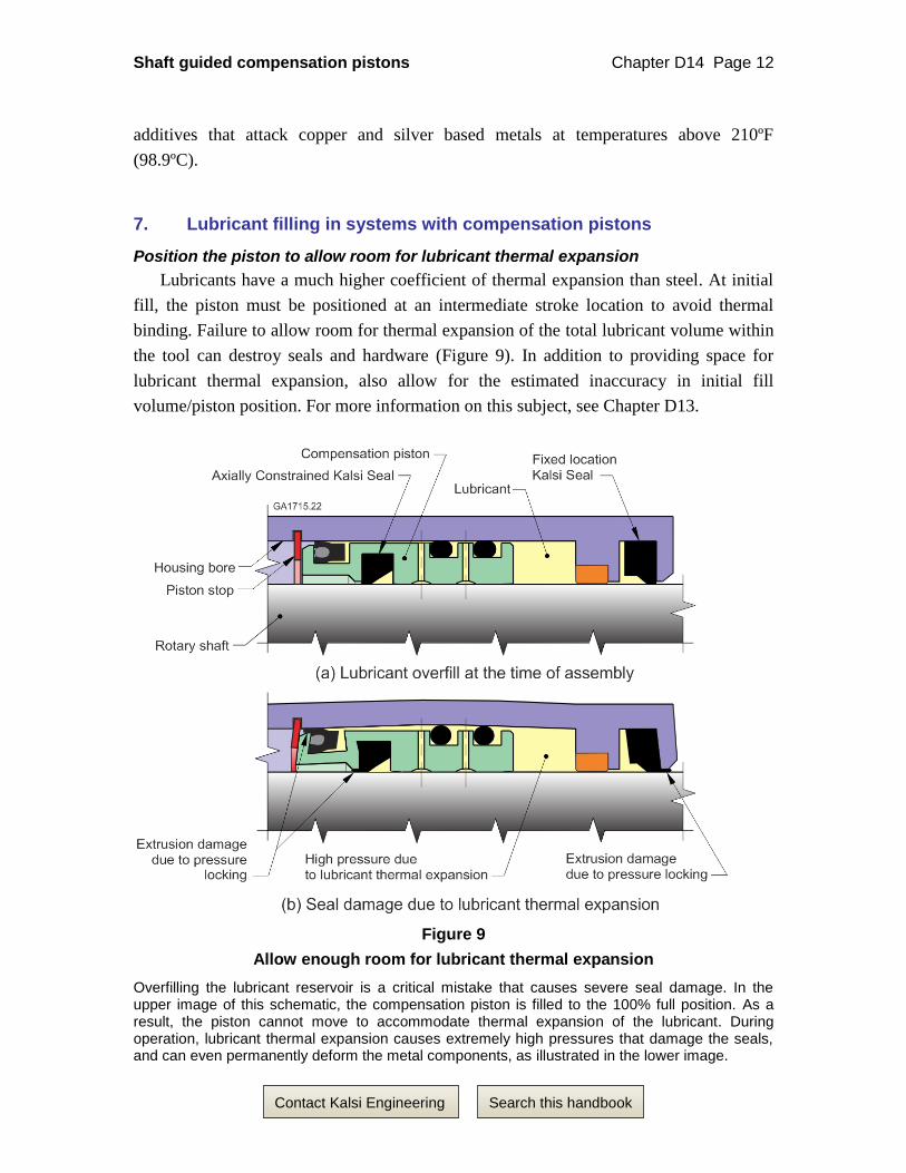
7. Lubricant filling in systems with compensation pistons
Position the piston to allow room for lubricant thermal expansion
Lubricants have a much higher coefficient of thermal expansion than steel. At initial
fill, the piston must be positioned at an intermediate stroke location to avoid thermal
binding. Failure to allow room for thermal expansion of the total lubricant volume within
the tool can destroy seals and hardware (Figure 9). In addition to providing space for
lubricant thermal expansion, also allow for the estimated inaccuracy in initial fill
volume/piston position. For more information on this subject, see Chapter D13.
Figure 9
Allow enough room for lubricant thermal expansion
Overfilling the lubricant reservoir is a critical mistake that causes severe seal damage. In the upper image of this schematic, the compensation piston is filled to the 100% full position. As a result, the piston cannot move to accommodate thermal expansion of the lubricant. During operation, lubricant thermal expansion causes extremely high pressures that damage the seals, and can even permanently deform the metal components, as illustrated in the lower image.

Shaft guided compensation pistons Chapter D14 Page 13
Search this handbook Contact Kalsi Engineering
Avoid trapping large amounts of air in the lubricant supply
In oilfield mud motors (and other equipment used in high ambient pressure
environments) one must avoid trapping large amounts of air in the system, because the
high lubricant pressure will collapse the air pockets, potentially causing the piston to
bottom out at the empty position. If this happens, the entire ambient downhole pressure
acts across the rotary seals. This causes rapid seal destruction, and (because of extreme
downhole ambient pressures) may even damage (yield) the metal components.
Air entrapment must also be avoided in applications with vertically oriented shafts,
because the air will rise to the top of the assembly. The resulting air pocket may starve
the upper Kalsi Seal for lubricant, leading to premature failure. If vacuum filling
techniques are not used, systems with lubricant hoses may require purging to eliminate
air from the hoses.
Barrier compensation piston initial fill & stroke length
Figure 1 shows an example of a barrier compensation piston implemented in a mud
motor sealed bearing assembly to protect the high pressure seal from abrasives. As with
pressure compensation pistons, a barrier compensation piston must be filled initially to an
intermediate stroke position so that stroke is available to accommodate lubricant thermal
expansion. For more information on this subject, see Chapter D10.
In addition to lubricant thermal expansion, the barrier compensation piston may have
to accommodate a differential leakage rate between the high pressure seal and the barrier
seal. One basis for determining barrier seal stroke length would be to take into account
the known leakage data scatter from various tests at a given temperature (Section C).
Alternately, select a fixed location Kalsi Seal that has a greater hydrodynamic
pumping rate than the barrier seal, and provide a means to vent excess barrier lubricant to
the environment.
8. Spring loading the pressure compensation piston
Because of the friction of the sliding and anti-rotation seals, a pressure compensation
piston does not always balance the lubricant pressure exactly to the environment
pressure. During periods of lubricant thermal expansion, the lubricant pressure tends to
be higher than the environment pressure. As the lubricant is slowly consumed by the
hydrodynamic pumping related leakage of the Kalsi Seals, the lubricant pressure drops to
a value that is lower than the environment pressure. When the pressure difference is
enough to overcome seal friction, the pressure compensation piston moves axially and
lubricant pressure becomes more equalized to the environment. During the intervals when
the lubricant pressure is equal to or less than the environment pressure, a non-axially

Shaft guided compensation pistons Chapter D14 Page 14
Search this handbook Contact Kalsi Engineering
constrained Kalsi Seal is prone to the skew and shuttling related wear mechanisms
described in Chapter D9.
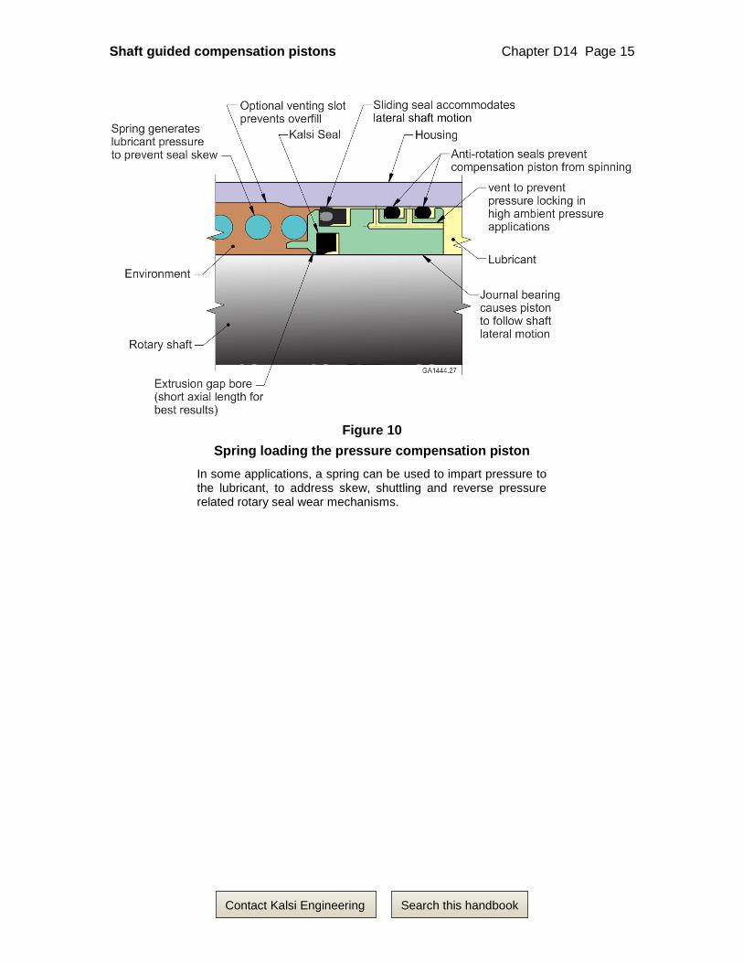
One way to combat skewing and shuttling related wear mechanisms is to spring load
the pressure compensation piston to overcome sliding seal friction and impart extra
pressure to the lubricant11, as shown in Figure 10. While shown with a non-axially
constrained Kalsi Seal, the spring loaded arrangement is also beneficial to Axially
Constrained Kalsi Seals because the spring can reduce or eliminate the occasions where
the environment pressure is higher than the lubricant pressure. This technique should
only be used in applications where the environment remains liquid enough to
accommodate spring movement.
Ideally, the spring force needs to be strong enough to overcome the piston friction,
and maintain a differential pressure that is sufficient to prevent seal skewing, even in the
depleted position of the piston stroke. This requires a differential pressure of at least
15 psi (103 kPa) at 162°F (72.2°C), and at least 22 psi (15 kPa) at 375°F (190.6°C) based
on testing with 2.75” ID seals.
Kalsi Engineering provides compression spring design software to assist customers
who are designing spring loaded lubricant reservoirs. The spring material must be
compatible with the environmental chemicals and temperature. The spring must be
designed so that it will not bind in the bore when fully compressed, in the maximum
material condition. Spring loading of the piston may not be possible in larger diameter
equipment because the spring mean diameter to spring wire diameter index may become
impractical. This “spring index” should normally be in the range of 4 to 16. The preferred
range12 is 5 to 12.
Venting excess thermally expanded lubricant to prevent overfill
If desired, the housing can incorporate a longitudinal venting slot to prevent lubricant
overfilling and associated lubricant thermal expansion related pressure locking. When the
sliding seal travels onto the slot, the slot vents lubricant past the sliding seal and into the
environment. The end of the slot has to be chamfered to ease the sliding seal back into the
unslotted portion of the housing bore, and the spring has to be strong enough to cause the
sliding seal to reengage with the unslotted portion of the housing bore under all
anticipated operating conditions.
11 For additional information on the use of spring loaded pressure compensation pistons in oilfield downhole tools,
see expired U.S. Patent 4,372,400.
12 The spring index range of 5 to 12 is from the “Mechanical Spring Design Guide”, by Green and Mather
(Rockwell International, 1973).
Shaft guided compensation pistons Chapter D14 Page 15
Search this handbook Contact Kalsi Engineering
Figure 10
Spring loading the pressure compensation piston
In some applications, a spring can be used to impart pressure to the lubricant, to address skew, shuttling and reverse pressure related rotary seal wear mechanisms.
Shaft guided compensation pistons Chapter D14 Page 16
Search this handbook Contact Kalsi Engineering
9. Spring loading a Kalsi Seal in a compensation piston
The compensation pistons shown in Figures 11 and 12 fit in the same space as the
piston of Figure 2. Instead of using an Axially Constrained Kalsi Seal, the pistons in
Figures 10 and 11 employ a backup washer and springs to axially preload a Wide
Footprint or High Temperature Kalsi Seal to inhibit skew induced abrasive wear. This
arrangement can be used in cases where an Axially Constrained Seal is not available in
the correct size or temperature range. For more information on spring loading Kalsi
Seals, see Chapter D9.
The compensation pistons have front and rear members that have a close sliding fit
with each other, and are locked together by three equally spaced radial retaining pins
captured by the housing bore. (The holes for the radial retaining pins are match drilled
and reamed.) The pistons can be quickly disassembled to replace the Kalsi Seal by
removing the pins.
When the environment pressure exceeds the lubricant pressure, the resulting
hydraulic force can compress the springs and cause axial travel of the Kalsi Seal. As
shown in Figure 11, the backup washer (or the removable groove wall formed by the
journal bearing) may incorporate one or more projections to limit travel so that the
distance between the environment side groove wall and the backup washer cannot exceed
the groove width needed to accommodate the thermally expanded seal width. Detailed
information on designing spring loaded Kalsi Seal implementations is provided in
Chapter D9. Information on seal width at elevated temperature is provided in
Appendix 2.
As with the compensation pistons described earlier, the sliding seal of Figures 11 and
12 establishes a sealed relationship with the housing bore, and the anti-rotation seals
provide extra friction to prevent piston spinning. To prevent pressure locking, the holes
for the radial retaining pins, the piloting fit between the piston members, and the cross-
drilled vent, defeat the sealing function of the anti-rotation seals.

Shaft guided compensation pistons Chapter D14 Page 17
Search this handbook Contact Kalsi Engineering
Figure 11
A compensation piston with a wave spring loaded Kalsi Seal In this oilfield mud motor pressure compensation piston, the Kalsi Seal is axially preloaded with a wave spring to prevent skew induced wear. Three radial retaining pins in match-reamed holes are used to hold the assembly together. In an R&D mud motor that Kalsi Engineering built to obtain firsthand field experience, the journal bearing portion of this seal carrier was bearing bronze.

Shaft guided compensation pistons Chapter D14 Page 18
Search this handbook Contact Kalsi Engineering
Figure 12
A compensation piston with a coil spring loaded Kalsi Seal In this oilfield mud motor pressure compensation piston, the Kalsi Seal is axially preloaded with a circle of coil springs to prevent skew induced wear. Three radial retaining pins in match-reamed holes are used to hold the assembly together. The backup washer is keyed to the piston to prevent rotation that could bind the projecting ends of the springs. If desired, the anti-rotation tangs could be axially oriented, instead of radially oriented. The face of the backup washer can be grit blasted to inhibit circumferential slippage of the Kalsi Seal.

Shaft guided compensation pistons Chapter D14 Page 19
Search this handbook Contact Kalsi Engineering
10. Incorporating a barrier seal in a compensation piston
Figure 13 Shows that a lip-type barrier seal can be mounted outboard of the Kalsi
Seal, to provide a degree of redundancy. The arrangement that is shown is configured for
a high ambient pressure environment. The barrier lubricant between the Kalsi Seal and
the barrier seal is pressure compensated to the environment by a radially acting O-ring
which is axially compressed in a deep groove.
The pressure of the environment pushes the O-ring radially inward, compressing any
entrained air within the barrier lubricant, and equalizing the pressure of the barrier
lubricant to that of the environment.
The mouth of the deep groove is chamfered to facilitate installation of the radially
acting O-ring. The type of barrier seal that is illustrated is an A6R seal, which is a
product of CDI Energy Services. It is a spring loaded elastomer seal with a reinforced
PTFE heel. The elastomer portion is available in HNBR or FEPM. The FEPM option is
appealing from a chemical resistance standpoint, especially for oilfield downhole
applications such as mud motors and rotary steerable tools.
Figure 13
Incorporating a barrier seal in a compensation piston The radial stroke of the radially siding O-ring helps to compensate for an incomplete lubricant fill in the region between the Kalsi-brand rotary seal and the lip-type barrier seal. Smaller O-ring cross-sections have more radial stroke, which may be an important consideration when radial space is cramped.

Shaft guided compensation pistons Chapter D14 Page 20
Search this handbook Contact Kalsi Engineering
11. Installing sliding seals into compensation piston grooves
The sliding seals of a compensation piston are often quite stiff and difficult to install
by hand. The recommended way to install such seals is as follows. First, warm the seal up
to soften and thermally expand it. Second, start the seal into its groove on one side of the
piston. Third, slip an O-ring under the opposite side of the seal, and then pull on the
resulting two loops of the O-ring, using it as a tool to work the sliding seal into its groove
(Figure 14). Finally, pull the O-ring free, and give the sliding seal enough time to
gradually retract to its original diameter.
Figure 14
An O-ring can be used as a tool to install a piston sliding seal