Embed Size (px)
Citation preview

SGOES OPERATION MANUAL 820-0006 Rev 03 03/07/13
SGOES Infrared Hydrocarbon Gas Detector
Operation Manual 820-0006 REV: 03

SGOES OPERATION MANUAL 820-0006 Rev 03 03/07/13
Table of Contents
INTRODUCTION 4
ORDERING GUIDE 4
SPECIFICATIONS OF SGOES 5
OPERATIONAL CHARACTERISTICS 5 ELECTRICAL CHARACTERISTICS 5 MECHANICAL CHARACTERISTICS 6
APPLICATION 7
OPERATIONAL DESCRIPTION 7
OPERATION CONCEPT 7 OPTICS PROTECTION 7 EXPLOSION PROOF INTEGRITY 8 IMPORTANT SAFETY INFORMATION 8 TRANSPORTATION AND STORAGE 8 PROTECTIVE COVER 8 INTERNAL OPTICS HEATER 8 CERTIFICATIONS AND COMPLIANCE 9 CAUTIONS AND WARNINGS 10
START-UP 11
PRIOR TO START-UP 11 START-UP PROCEDURE 11 HART DEDICATED CONNECTOR 11 RS-485 MODBUS DIGITAL COMMUNICATION AND OPERATION 12 ESP-COMMANDER SOFTWARE 12 CALIBRATION PROCEDURES 12 METHODS OF PERFORMING CALIBRATION 13 CALIBRATION PROCEDURES SGOES OPERATION CONCEPT REVIEW 13
NON-INVASIVE MAGNETIC “WAND” CALIBRATION PROCEDURE 14
REQUIRED EQUIPMENT FOR NON-INVASIVE MAGNETIC CALIBRATION. 14
NON- INVASIVE CALIBRATION PROCEDURE WITH HART COMMUNICATOR 15
REQUIRED EQUIPMENT FOR HART COMMUNICATOR CALIBRATION PROCEDURE 15 HTTP://WWW.HARTCOMM.ORG 15
RS-485 MODBUS CALIBRATION 17
LAUNCH ESP COMMANDER 17 AVAILABLE FUNCTIONS FOR ESP COMMANDER 17

SGOES OPERATION MANUAL 820-0006 Rev 03 03/07/13
ANALOG OUTPUT CONFIRMATION 19
APPENDIX I: CALCULATING VALUES 20
SGOES NOMINAL STATIC CONVERSION FORMULA 20
APPENDIX II: GAS MEASUREMENT SCALE RANGE 21
APPENDIX III: GAS FLASHPOINT TEMPERATURES 21
APPENDIX IV: TERMINAL BLOCK & WIRING FOR 3-WIRE & 4-WIRE SYSTEMS 22
APPENDIX V: MAXIMUM CABLE LENGTHS 23
APPENDIX VI: LOCATION OF THE INSTALLATION SITE 23
APPENDIX VII: MAINTENANCE REQUIREMENTS 24
APPENDIX VIII: HART MENU TREE 25
APPENDIX IX: SGOES TO SSS-903 INTERCONNECT 26
APPENDIX X: SGOES TO VECTOR DISPLAY INTERCONNECT 27
APPENDIX XI: SGOES TO UPES 28
APPENDIX XII: SGOES TO ANALOG INPUT MODULE 29
APPENDIX XIII: TROUBLESHOOTING 30
APPENDIX XIV: WARRANTY 31

SGOES OPERATION MANUAL 820-0006 Rev 03 03/07/13
Specifications Page 4 of 31
Introduction
ESP Safety Inc. designs and manufactures affordable safety products and protection solutions for industrial safety and fire protection. Our company is committed to partner with our customers, contractors, and Architects in their design process to create a system that best meets the specification. After the system is installed, ESP Safety offers customer assistance via Telephone, Email, or Instant Message. On site commissioning services and field support are available to ensure and maintain the protection of lives and infrastructure in hazardous environments. Our line of industry-leading products, services, and systems benefit society, save lives, and preserve capital resources.
Ordering Guide
SGOES can detect a number of Hydrocarbon based Gases and Vapors. For simplicity of ordering and eventual installation, the SGOES is factory prepared and ordered for detection of eight user specified gases and scale ranges.
Scale Range
SGOES Model to Order
Detected Hydrocarbon
%LEL %vol IEC6007920-
2000/BSEN617791:2000 %vol ISO 10156
SGOES-CH4 Methane 0 to 100 0 to 4.4 0 to 5.0
SGOES-C3H8 Propane 0 to 100 0 to 1.7 0 to 2.1
SGOES-C4H10 Butane 0 to 50 0 to 0.7 0 to 0.9
SGOES-iC4H10 Isobutane 0 to 50 0 to 0.65 0 to 0.9
SGOES-C5H12 Pentane 0 to 50 0 to 0.7 0 to 0.75
SGOES-C5H10 Cyclopentane 0 to 50 0 to 0.7 0 to 0.75
SGOES-C6H14 Hexane 0 to 50 0 to 0.5 0 to 0.55
SGOES-C3H6 Propylene/Propene 0 to 50 0 to 0.1 0 to 1.5
SGOES-CH3OH Methanol Vapor 0 to 50 0 to 2.75 0 to 3.65
SGOES-C2H5OH Ethanol Vapor
0 to 25 0 to 50
0 to 0.78 0 to 1.55
0 to 1.08 0 to 2.15

SGOES OPERATION MANUAL 820-0006 Rev 03 03/07/13
Application & Operational Description Page 5 of 31
Specifications of SGOES
Operational Characteristics
Gases that can be detected
Methane, Propane, Butane, Pentane, Hexane, Isobutane, Cyclopentane, Ethanol. (The target gas is factory configured according to customer request.)
Gas Detected Range 0 to 100% LEL (lower explosive level – in air)
Accuracy ±3% LEL, for 0 to 100% LEL
Response Time (For 100% LEL Methane)
50% full scale < 1.9 seconds 90% full scale < 5.0 seconds
Humidity Range Up to 100%, non-condensing (Withstands up to 100% RH for short periods)
Warm Up Time 10 Minutes
Operating Temperature -60oC to +85oC
Storage Temperature -75oC to +185oC
Ingress Protection IP66
RFI/EMI Protection EN50081-1 / Class B E> 50270 *Operates with no interference from a 5 watt walkie-talkie keyed (transmitting) at 1 meter
Status Indication Tri-color status LED indicates operational mode, fault, and gas presence.
Optional SGOES Receiver Displayed Information (Model SSS-903 Illuminated LCD Display)
Continuous sensor data Gas Type Measuring Units Three Fixed Alarm Thresholds Graphic display of trending data for Peak Readings and Time-Weighted Average (TWA) of gas concentration 3-30 minutes
Explosion Proof Labels Class I, Division 1 & 2, Group C & D T4 according to FM 3600. Ex d [ia Ga] IIC T6 Gb Ex d ia IIC T6
Electrical Characteristics
Input Voltage +24VDC Nominal (+18 to 32VDC)
Power Consumption 7.9 W maximum
Output From SGOES +4-20mA industry standard analog with embedded HART Digital RS-485 MODBUS RTU HART interface with easy access dedicated connector 3 “Dry Contact” relays. Fault relay (NC/Form-B), alarm level 1 (NO/Form-A), alarm level 2 (NO/Form-A). All Relays Contact Rating 1Amp@125VAC/30VDC
Alarm Relays 2 User Programmed Alarm Relays 1 Fault Condition Relay

SGOES OPERATION MANUAL 820-0006 Rev 03 03/07/13
Specifications Page 6 of 31
Mechanical Characteristics
SGOES with the included Mounting Bracket is available in 2 Enclosure Construction Metals
Stainless Steel Grade-316 Aluminum Alloy
Cable Entry 2 Cable Entries ¾” NPT
Weight With Bracket Stainless Steel Grade-316 6.5kg Aluminum Alloy 4.2kg
Physical Dimensions 200x200x100mm
Optics Protection Weather Proof Cover
Wiring 14AWG Recommended
Included Components SGOES orders when delivered from the factory include:
SGOES gas detector
Mounting Bracket
Dust and Moisture Protective Housing
Screw Clamp Connector Kit
Available Options Calibration Kit with Zero and Span Gasses
SSS-903 visual display
HART Connection Cable
Magnetic Calibration Wand
ESPCommander installation CD
RS485 Converter
Gas Calibration Cover

SGOES OPERATION MANUAL 820-0006 Rev 03 03/07/13
Application & Operational Description Page 7 of 31
Application
SGOES units are used in dangerously explosive areas of indoor and outdoor facilities providing reliable detection for a wide range of applications in accordance to IEC60079-14-96. The SGOES is explosion proof, making it the detector of choice for several industries and environments, which include:
Drilling and Production Platforms
Ocean Going Tankers and Vessels
Fuel Loading Facilities
Refineries
Bulk Terminals and Tank Farms
LNG/LPG Process and storage Facilities
Compressor Stations
Pipeline Facilities SGOES has a very low occurrence of false/positive alarms and is ideal for automated warning, control, and suppression system designs used in unmanned and centrally controlled applications. Non-invasive calibrations can be performed in the field using a magnetic wand or a Hart communicator. Calibration can also be performed with a Windows PC application, ESP Commander.
Operational Description The SGOES Combustible Gas Detector measures the concentration of hydrocarbon gases present in the monitored environment. Each SGOES is factory calibrated to detect one of eight hydrocarbon-based gases (typically methane or propane). The SGOES will activate two alarms when the gas concentrations in the environment reach two independently programmed levels, which are expressed as a percentage of the lower explosive limit (LEL) in air.
ESP has designed the SGOES to detect and quantify the presence of hydrocarbons by measuring their absorption of infrared light (IR). Because SGOES does not depend on the presence of oxygen in a mixture of gases, it can function effectively in environments where other sensor technologies cannot, therefore it is the de
facto standard for oil platforms that commonly have air temperatures below 44°С, with high waves and ice buildups in excess of 5.5 ft. (170 cm). Moreover, SGOES is not sensitive to inadvertent detection of gases, such as nitrogen, oxygen, carbonic acid, ammonia, and hydrogen sulfide. This makes the SGOES an excellent choice for environments where non-hydrocarbon gases are present and precise monitoring of combustible hydrocarbons like methane and propane is required. All electronics are enclosed in an explosion-proof aluminum or stainless steel housing which has been certified by FM-Approvals as an Explosion proof CLASS 1, Division 1 (Zones-0,1,2 EU) device for use in hazardous locations as defined by the United States National Electric Code (NEC).
Operation Concept
Operation is based on selective signal disruption by hydrocarbon molecules when an infrared light source is reflected to an optical detector. If no gas is present, the detector will receive all of the energy radiated by the IR source and generating an electrical current. When gas molecules enter the collection chamber, each molecule of the gas blocks the IR energy reducing the output of the detector, which is then processed by the SGOES.

SGOES OPERATION MANUAL 820-0006 Rev 03 03/07/13
Specifications Page 8 of 31
Explosion Proof Integrity SGOES is designed to be explosion-proof thus SGOES units installed and in operation must not be modified in any form. All labeling must be intact and visible. All surfaces that are subject to disassembly or removal during installation or maintenance must be installed as detailed in Appendix I and comply with the FM3615 standard when replaced. The enclosure explosion protection marking is: Class I, Division 1 & 2, Group C & D, T4 according to FM 3600. SGOES Explosion proof means are detailed in Appendix VII of this document. Explosion protection of SGOES is ensured by: Cabling entering into and out of the SGOES must utilize explosion-proof gland connections. The cable gland should be able to withstand explosion pressure and prevent spread of combustion into the hazardous area. The connection points are marked in the drawings with word “Explosion” and indicate permissible values of the explosion-protection parameters must comply with FM3615. Limit the enclosure outer temperature to no higher than 135 °C. All the bolts securing the parts and enclosure must be sufficiently tightened and prevented from loosening by using spring washers or lock nuts.
Optics Protection
The weather baffle assembly is UV-resistant, static-dissipating black plastic. The standard is recommended for most outdoor and indoor applications, includes an internal hydrophobic filter.
IMPORTANT SAFETY INFORMATION Be sure to read and understand the entire instruction manual before installing or operating the gas detection system. The products described in this document can be used with a variety of ESP-Safety gas detector models to provide early warning of the presence of a toxic or explosive gas mixture. Proper device installation, operation, and maintenance is required to ensure safe and effective operation. If this equipment is used in a manner not specified in this manual, safety protection may be impaired.
TRANSPORTATION AND STORAGE
SGOES as packed by ESP Safety Inc. can be transported by any transportation means.
Protective Cover
The black protective cover is provided to prevent debris and water from entering the optics, while allowing gases and vapors to enter readily. Protective Covers are not field-serviceable, but are easily replaceable. The Protective Cover is furnished with a calibration gas nozzle for direct injection of gas to the sensor, allowing the operator to apply gas to the detector without going through the weather baffle. NOTE: Always cover the calibration gas nozzle with the cap during normal operation, and ensure that the cap is not damaged.
Internal Optics Heater Each SGOES includes a heating system that will serve to keep the optics free of moisture and increase operating temperature range in extreme cold environments.

SGOES OPERATION MANUAL 820-0006 Rev 03 03/07/13
HART Calibration Menu Tree Page 9 of 31
Certifications and Compliance
Explosion-proof for Class 1, Div.1, Group B, C, D (T4) Hazardous (classified) locations per FM 3615, 6310 Dust ignition-proof for Class II, Div.1, Group E, F, G Hazardous (classified) locations per FM 3615, 6310 Non-incendiary for Class 1, Div.2, Group A, B, C, D (T4), Class 2, Div.2, Group E, F, G (T4) Hazardous (classified) locations per FM 3611 Performance verified up to 100% LEL methane-in-air atmosphere per FM 6320
Explosion-proof for Class 1, Div.1, Group B, C, D (T4) Hazardous (classified) locations per CSA C 22.2 # 30 and Ex d IIC T4 per CSA E 60079-0-1 Dust ignition-proof for Class II, Div.1, Group E, F, G Hazardous (classified) locations per CSA C 22.2 # 25 Non-incendiary for Class 1, Div.2, Group A, B, C, D (T4), Class 2, Div.2, Group E, F, G (T4) Hazardous (classified) locations per CSA C 22.2 # 213 Performance verified up to 100% LEL methane-in-air atmosphere per CSA C 22.2 # 152
CE 0539 II 2 G Ex d[ia] IIC T4 (Tamb 75°C) IP 66
Ex d [ia] IIC T4 (Tamb 75°C) IP 66
1 Ex d [ia] IIC T4 X T= -60°C....75°C IP 66
EN Standards
EN 60079-0: 2006 EN 60079-1: 2007 EN 61779-1: 2000 EN 60529: 1991+A1: 2000 EN 50270: 2006.

SGOES OPERATION MANUAL 820-0006 Rev 03 03/07/13
Page 10 of 31
Cautions and Warnings
This user guide includes numerous cautions and warnings that are specifically included to prevent injury to personnel and prevent damage to equipment. Care is also taken to include notation of all applicable standards and best practices as appropriate information that may apply to any use or procedure associated with the product.
WARNING: TOXIC, COMBUSTIBLE, AND
FLAMMABLE GASES OR VAPORS ARE VERY DANGEROUS. USE EXTREME CAUTION WHEN THESE HAZARDS ARE PRESENT.
WARNING: Take appropriate precautions, including wearing and use of protective clothing and
devices when servicing the SGOES as they may have remnants of corrosive solutions
Caution: The installation of SGOES must comply with relevant requirements of the latest edition of the national Electric Code
(ANSI/NFPA 70) Caution: Connection Conduit, Barrier Glands, and Epoxy Sealants are to meet EN-50018/IEC 60079-1 Standards
Caution: ESP Safety Inc. Recommends use of shielded cable with 16AWG conductors reaching a span no greater than 6500 ft.
(20000 meter)
Caution: The SGOES detector has no user serviceable parts. If a problem should develop, refer to the Troubleshooting information in
Appendix IX. If it is determined that the problem is caused by a manufacturing defect, please return the device to the factory for repair or replacement.
Caution: Observe precautions for transport and handling of electrostatic sensitive devices.
Caution: SGOES detectors have been tested and approved for use in hazardous areas. However, it must
be properly installed and used only under the conditions specified within this manual and the specific approval certificates. Any device modification, improper installation, or use in a faulty or incomplete configuration will render warranty and product certifications invalid.
2

SGOES OPERATION MANUAL 820-0006 Rev 03 03/07/13
Page 11 of 31
Prior to Start-up Once the mounting, cabling, and alarm relay installation has been completed, the SGOES is ready to begin the power-on sequence. Before applying power to the system for the first time, review the steps below:
Verify that the SGOES has been properly mounted. Ensure that all conduit / cable gland entries have been tightened and sealed if necessary.
Verify that all of the signal wires have been installed correctly.
Verify connection of earth/ground to the enclosure.
Verify the connections between the SGOES housing and any control room devices and alarm systems.
Make sure to turn off or disconnect any external devices, such as Trip Amplifiers, PLC devices or DCS systems, until after the startup sequence has been completed. Once you are ready to begin startup, verify that the power supply is connected properly and verify input voltage with the SGOES disconnected at the source. The SGOES is powered by 24 VDC. Startup Procedure: Before the initial power up, remove power from or disconnect all output devices and alarms to prevent actuation. Apply power to the system. The Tri-State Status LED will cycle Red, Green Yellow, indicating self-test is being performed. After 40 to 60 seconds the self-test initialization sequence will be completed. At this time the unit will be in the normal operational state. Alarm relays will be (Open) and Status Indicator Green. Allow the SGOES to warm up for 10 minutes for detection of accurate gas level measurements. If the detected area is gas free, the +4 to 20mA will output +4mA.
Digital Data Communication The SGOES provides three digital communication methods: HART (Highway Addressable Remote Transducer) accessible via a dedicated connector that is located on the SGOES housing. HART over +4 to 20 mA output Digital RS-485 MODBUS-RTU (Remote Terminal Unit)
HART Dedicated Connector
HART is a bi-directional communication protocol that provides data access between intelligent field instruments and host systems. In most applications for SGOES the host is an ESP-Safety specific software application available from the HART Foundation for use on a technician's hand-held HART communicator device. A HART system in considered non-invasive in that the SGOES does not have to be opened or removed from a field installed location.
HART communicators can access:
Information detected gas type
The measuring range in LEL%
Value of current gas concentration
State and programming of fixed alarm thresholds
Calibration
Zero Calibration
Download of Non-Volatile Memory

SGOES OPERATION MANUAL 820-0006 Rev 03 03/07/13
Page 12 of 31
RS-485 MODBUS Digital Communication and Operation
The MODBUS interface is used for communication to all ESP Safety Detector models. Up to 255 devices can be connected in a Networked system. MODBUS® RTU protocol uses ASCII/Hex data for communication and allows all SGOES functions to be transmitted using this method. MODBUS protocol is a Master-Slaves protocol, meaning a single Master Device (PLC, SCADA, ESP SSS-903 Receiver, ESP-UPES Controller, or a Windows PC with ESP Commander Software) will send a message to each device to poll, or ask it, for available information, which the device will then return. Each device has a unique identifying address (Set by the user with ESP Commander Software) The MASTER device will talk to each device individually at an interval that is also set by the user (Thus the term “Poll”) MODBUS® is a registered trademark of Schneider Automation Inc.
ESP-Commander software
SGOES with SSS-903 Receiver
The MODBUS interface can also be connected to an ESP-Safety SSS-903 Receiver. By incorporating the SSS-903 the user can have a graphic display for monitoring the concentration readings and alarm levels of SGOES plus alarm indications. SSS-903 and the SGOES communicate via MODBUS and receive power by using a serial “Daisy Chain” connection method. Refer to Appendix VIII for connections diagram.
Calibration Procedures Warning: Trained staff must perform all calibration procedures. The calibration procedure work area must be a safe distance from any
hazardous gas or material. Follow all site safety operating procedures before removing any detector from service.
SGOES OPERATION MANUAL 820-0006 Rev 03 03/07/13
Page 13 of 31
Methods of Performing Calibration
There are three methods available to perform calibration of the SGOES Using RS-485 MODBUS with the ESP-Commander control Program (Remote or Bench Test Method) Using a HART Communicator (Non-invasive In Field or Bench Test Method) Using a Magnetic “Wand” (Non-invasive In Field or Bench Test Method, No Instrument or tools required) or tools required)
Warning: All alarms must be disconnected to eliminate the possibility of erroneous alarm activation when performing this procedure.
Caution: Before starting the calibration and verification procedure, inspect the SGOES fore any mechanical damages. Please contact the ESP Safety Inc service department for
further information.
Calibration Procedures SGOES Operation Concept Review
The SGOES gas detector operates on the principal of selective absorption of radiation by hydrocarbon molecules. Primary components of the SGOES gas detector consist of optoelectronic and data input compartments within an explosion-proof enclosure. The data input compartment houses infrared sources and receivers along with the signal conditioning electronics. Infrared emissions penetrate into an unsealed compartment where the gas mixture is analyzed. A mirror reflects the infrared emission back into photo detectors in the data input compartment. The signal is amplified and processed for conversion to an output with a current range of 4 to 20 milliamps. The amperage of the output corresponds to a range of measured gas concentrations of 0 to 100% LEL (lower explosive level). Output signals from the SGOES gas detector are available from the clamp terminals mounted inside the explosion-proof data input compartment.
WARNING: Do not connect or disconnect the SGOES detector with power applied. This action is prohibited by regulations of operation in a hazardous area.

SGOES OPERATION MANUAL 820-0006 Rev 03 03/07/13
Calibration with HART Page 14 of 31
Non-Invasive Magnetic “Wand” Calibration Procedure Non-Invasive Zero set and Calibration up can be performed on SGOES detectors when installed in the permanent location by using a magnetic Wand.
Required Equipment for Non-Invasive Magnetic Calibration
•¼” PVC Tubing. •ESP Safety Zero Gas and Span Gas disposable canister for the appropriate gas. •Calibration Cup. •ESP Safety Magnetic Wand.
Warning: Do not forget set gas calibration point with ESP Commander or Field Communicator.
1)Put a magnetic wand next to the LED. LED will start to blinks green (sensor in the calibration mode, output signals are blocked). 2)Put the calibration cup on the SGOES detector and apply pure nitrogen. Then put a magnetic wand next to the LED second time. LED will start to blinks red (sensor set zero point). 3)Apply gas on the detector and wait about two minutes (gas concentration inside the canister should match to preset gas calibration point). Then put a magnetic wand next to the LED third time. LED will start to lights red constantly (calibration is made). 4)Remove the calibration cup from the detector and wait till LED start to blinks green. 5)Put a magnetic wand next to the LED fourth time. LED will start to lights green constantly (sensor out of calibration mode, the output signals are enabled). If you don’t apply any gas on the detector after step two and you put a magnetic wand next to the LED, LED will start to lights green constantly (sensor out of calibration mode, the output signals are enabled). You only calibrate zero point. If you do not do anything for three minutes after step two LED will start to lights green constantly
(sensor out of calibration mode, the output signals are enabled). You only calibrate zero point.

SGOES OPERATION MANUAL 820-0006 Rev 03 03/07/13
HART Calibration Page 15 of 31
Non- Invasive Calibration Procedure With HART Communicator
Required Equipment For HART Communicator Calibration Procedure•¼” PVC Tubing. •ESP Safety Zero Mid Span and Span Gas disposable canister for the appropriate gas. •Calibration Cup. •User Supplied Emerson 475 Hart Communication Device. •ESP Safety Hart Connection Cable. •Device driver for ESP Safety Products. *Available from the Emerson company website www.emersonprocess.com
1) ESP Safety recommends using Emerson 475 HART communicator. Firmware version of your HART communicator should not be lower then 3.6. Use the Emerson Easy Upgrade Utility if you need to upgrade your firmware. Connect the communicator to the HART interface socket of the SGOES using the ESP Safety supplied cable. Apply Power to SGOES and allow it to warm up for at least 10 minutes if it has been powered down. Then turn on the HART. Double Click the HART symbol to establish communication between the devices. 2)The HART display will cycle through a test mode then change ask for information to create a file of the procedure in the HART Communicator. This can be performed or skipped at the user’s choice. To exit the File Storage menu select SAVE. 3) HART will now change to the SGOES “HOME” menu when communication is established. SGOES is automatically determined when the HART and SGOES establish a communication link.
THE SGOES menu has the following information that has been sent by the SGOES:
1 Hart Test 2 Device Setup 3 Gas Type: Gas type the detector is programmed for. 4 PV: Present value in %LEL detected by SGOES 5 SV: First Alarm (Relay) threshold 6 TV: Second alarm threshold 7 4V: Internal Temperature 8 PV Loop Current: Current loop output. Note: Clicking on the pulsing heart will call the help menu Note: Before proceeding: Remove the Protective Cover and install the Calibration Cup. Connect the ZERO gas supply tubing to the nipple of the Cal cup and begin a Purge with Gas flowing at 1-2 LPM for one minute. Note: In the following steps follow the menu prompts on the HART device

SGOES OPERATION MANUAL 820-0006 Rev 03 03/07/13
RS-485 MODBUS Calibration Page 16 of 31
HART Calibration Menu Tree

SGOES OPERATION MANUAL 820-0006 Rev 03 03/07/13
RS-485 MODBUS Calibration Page 17 of 31
RS-485 MODBUS Calibration
Several RSP Safety detectors can be calibrated remotely in the field or on a test bench using ESP Commander Note: The following example is for Propane only. Follow the same steps for the gas to be calibrated. Before the initial power up, remove power from or disconnect all output devices and alarms to prevent actuation. Apply power to the system. After 40 to 60 seconds the self-test initialization sequence will be completed. At this time the unit will be in the normal operational state - status Indicator Green. Allow the SGOES to warm up for 30 minutes for detection of accurate gas level measurements during calibration procedures. Required Equipment For RS 485 Modbus Calibration Procedure •¼” PVC Tubing. •ESP Safety Zero Mid Span and Span Gas disposable canister for the appropriate gas. •Calibration Cup.
Launch ESP Commander
Software Program must be installed on the user supplied PC interfaced to the user supplied RS-485 to USB converter. Select The COM port for the link between the PC and converter. ESP Commander will scan for all devices connected (via MODBUS communication protocol). Select the device to be calibrated by ESP Commander Operating Screen Display and Function.
Available Functions For ESP Commander: Device Model
Device relay state
Device Address
Version
Serial Number
Device Address Assignment
Detection Gas
Calibration Values
Alarm Values
Graph of Alarm events
Recording of Real Time Data
Polling Interval

SGOES OPERATION MANUAL 820-0006 Rev 03 03/07/13
RS-485 MODBUS Calibration Page 18 of 31
Note: The following example is for Methane only. Follow the same steps for the gas to be calibrated 1) Use the pull down to select the gas to match the labeling on the sensor.
The gas pull down is pre-programmed with the required LEL for the selected gas. In the following example the LEL for Methane is 5% of volume. 5% of Volume equals 100% LEL In this example, as per the labeling on the cylinders, the Zero Gas is Nitrogen, The Span Gas is approx 4.9% of volume and the Mid Span Gas is 2.5% of volume. Enter the highest Span gas value as Pri. Conc-% Vol and the Mid Span as 2.5.
2) ALARM THRESHOLDS Next enter the Alarm thresholds in %LEL by entering the value into the edit cells then clicking SET 3) Put the calibration cup on the SGOES detector and apply pure nitrogen using the Zero Gas Cylinder. After one minute, the Vol. Conc. And LEL windows of ESP Commander should read zero or close to it. Click on the Zero icon to complete the zero cal procedure. If measuring Current loop, the output will equal 4.0mA after setting Zero Cal
The Status LED on the SGOES Enclosure will illuminate Green. Turn of the Gas Flow on the Zero Cal cylinder when completed. 4) SPAN GAS CALIBRATION Attach the Span Gas Cylinder with the mixture value as required. Start a flow into the Calibration cup. After one minute, the real time display count will level at out approximately 4.9% for Vol. Concentration and 98%LEL. The Current loop output will equal 19.6mA. The Alarms will have become active as the thresholds are crossed. The LED on SGOES will turn Red when the first threshold is passed. Turn off the Gas flow from the cylinder before disconnecting any tubing. 5) MID SPAN CALIBRATION A second gas with a mixture equal to 50% LEL may be used for calibration of mid span. This would be the value set into the SEC. CONC. %Vol window.
Attach the Mid Span Gas Cylinder with the mixture value as required. Start a flow into the Calibration cup. After one minute, the real time display count will level at out approximately 2.5% for Vol. Conc. and 50%LEL. The Current loop output will equal 12mA. The Alarms will deactivate, in this case the alarm set for 60% LEL the thresholds are crossed. The LED on SGOES will turn Red when the first threshold is passed. 6) Turn off the Gas flow from the cylinder before disconnecting any tubing. Finally, remove the Calibration cup and allow the SGOES to normalize. At this point all alarms should be off. The Status LED will be Green. The Current Loop output will equal 4.0mA.

SGOES OPERATION MANUAL 820-0006 Rev 03 03/07/13
Analog +4 to 20mA Confirmation of Calibration Page 19 of 31
ANALOG OUTPUT CONFIRMATION
Zero Gas Confirmation of +4 -20mA Values 1. An LEL value of 0.0% will correspond to a + 4
mA output reading. 2. During the initial warm-up period of 30
minutes, the 4mA output value should be periodically monitored to confirm the reading remains stable
3. (+4mA means no gas is detected) 4. It is not necessary to flow Zero gas during the
entire warm-up period. If the environment is known to be free of any potential hydrocarbons, simply allow the detector to sit idle with gas off and power on and check periodically.
5. Remove the Protective Cover and attach the Calibration Cup.
Span and Mid Gas Confirmation using +4 -20mA. 1. Attach the Span Gas 2. Open the valve of the gas cylinder Allow the
gas to flow for at least 2 minutes before checking the current output for LEL Range.
3. An LEL value of top range for the selected gas will correspond to a 20 mA output reading. If the %LEL of the target gas is not listed in Table IA consult Appendix I to calculate the expected current output value.

SGOES OPERATION MANUAL 820-0006 Rev 03 03/07/13
Appendix I: Calculation Values & Conversion Formulas Page 20 of 31
Appendix I: Calculating Values
SGOES Nominal Static Conversion Formula
Nominal conversion of the SGOES employs the following formula: Ii =16Сi /CMAX +4 Ii is the output current value, in mA; Ci is the concentration value for the gas analyzed, % LEL CMAX is the maximum value of converted concentration, % LEL.). To determine the concentration of the detected gas in %LEL , calculate by the formula: Ci = 6.25(Ii-4) Under calibration with standard gas mixture, the measuring concentration of the detected component (in %LEL) is calculated by the formula: Ci = 100 Cpasp/Cp Cpasp is the value of the converted range of the detecting component concentration labeled on the cylinder of a specific control gas mixture. Cp is the upper value of the converted gas range of the detecting component equaling 100% LEL.
Calculation of absolute error
The absolute error is calculated using the formula:
Са= Сi-Сd Сi – gas analyzed indication under i is a control gas mixture in %vol and %LEL. Сd– real concentration of detecting component under I control gas mixture supplying %vol and % LEL
Example
Using a control gas mixture labeled 61.7 LEL. The Calculated value %LEL resulted 60% LEL. Calculate the measurement error of absolute error: Са=61.7 LEL-60%LEL =1.7 LEL
Thus the absolute error of this gas mixture is equal to 1.7 LEL. Relative error estimate of gas analyzer is calculated by formula:
б= (Сi-Сd/ Сd)х100
using the above to determine absolute error. б=(61.7-60/60)х100=2.8%
The calibration results are considered accurate if the basic error of gas analyzer calculated by the formulas given above in all calibrating points does not exceed limits of Table 1-A

SGOES OPERATION MANUAL 820-0006 Rev 03 03/07/13
Appendix IiI: Analog Output Values By Gas Table Page 21 of 31
Appendix II Gas Measurement Scale Range
Scale Range Limits of Basic Absolute Error
SGOES Model Detected Hydrocarbon %LEL %vol ISO %vol IEC Absolute Relative
SGOES-CH4 Methane 0 to 100 0 to 5 0 to 4.4 ± 3% (0 to 50%LEL)
± 5% (50 to 100%LEL)
SGOES-C3H8 Propane 0 to 100 0 to 2.1 0 to 1.7 ± 3% (0 to 50%LEL)
± 5% (50 to 100%LEL)
SGOES-C4H10 Butane 0 to 50 0 to 0.7 0 to 0.7 ± 3% LEL
SGOES-iC4H10 Isobutane 0 to 50 0 to 0.65 0 to 0.65 ± 3% LEL
SGOES-C5H12 Pentane 0 to 50 0 to 0.7 0 to 0.7 ± 3% LEL
SGOES-C5H10 Cyclopentane 0 to 50 0 to 0.7 0 to 0.7 ± 3% LEL
SGOES-C6H14 Hexane 0 to 50 0 to 0.5 0 to 0.5 ± 3% LEL
SGOES-C3H6 Propylene/Propene 0 to 50 0 to 0.1 0 to 0.1 ± 3% LEL
SGOES-CH3OH Methanol Vapor 0 to 50 0 to 0.1 0 to 2.75 ± 3% LEL
SGOES-C2H5OH Ethanol Vapor
0 to 25 0 to 50
0 to 0.78 0 to 1.55
0 to 0.78 0 to 1.55
± 3% LEL ± 3% LEL
Appendix III Gas Flash Point Temperatures
Detected Hydrocarbon
Boiling/Vapor Point at 1 atmosphere
Flash Point
Methane (CH4) -165O C -188O C
Propane (C3H8) -42O C -104O C
Butane (C4H10) -0.5O C -108O C
Isobutane (iC4H10) -11O C
Pentane (C5H12) 36O C -49O C
Cyclopentane 49O C -37O C
Hexane 69O C -23O C
Propylene/Propene -48O C -108O C
Methanol Vapor -64O C 11O C
Ethanol Vapor NA 13O C

SGOES OPERATION MANUAL 820-0006 Rev 03 03/07/13
Appendix VI: Location of the Installation Site Page 22 of 31
Appendix IV: SGOES Terminal Block & Wiring for 3-Wire and 4-Wire Systems
SGOES Terminal Block
24V 0V 24V 0V 420 485A 485B FLT FLT AL1 AL1 AL2 AL2
+24 VDC
0 VDC
+24 VDC
0 VDC
+ 4-20mA
RS-485A RS-485B FAULT ALARM1 ALARM2
Power Supply
4-20mA Receiver
24V 0V 24V 0V 420 485A 485B FLT FLT AL1 AL1 AL2 AL2
+24 VDC
0 VDC
+24 VDC
0 VDC
+ 4-20mA
RS-485A RS-485B FAULT ALARM1 ALARM2
Power Supply
4-20mA Receiver
3-WIRE CONFIGURATION
4-WIRE CONFIGURATION
Label
Function
Power Supply Output
+ _ _ +
Label
Function
Power Supply Output
+ _ _ +
SGOES OPERATION MANUAL 820-0006 Rev 03 03/07/13
Appendix VI: Location of the Installation Site Page 23 of 31
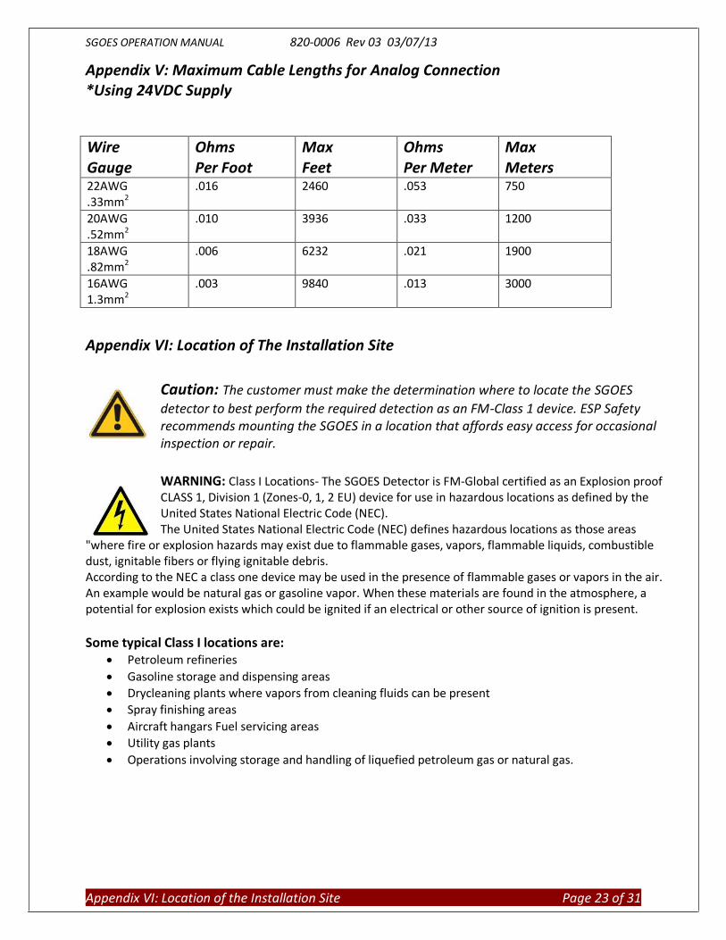
Appendix V: Maximum Cable Lengths for Analog Connection *Using 24VDC Supply
Appendix VI: Location of The Installation Site
Caution: The customer must make the determination where to locate the SGOES
detector to best perform the required detection as an FM-Class 1 device. ESP Safety recommends mounting the SGOES in a location that affords easy access for occasional inspection or repair.
WARNING: Class I Locations- The SGOES Detector is FM-Global certified as an Explosion proof CLASS 1, Division 1 (Zones-0, 1, 2 EU) device for use in hazardous locations as defined by the United States National Electric Code (NEC). The United States National Electric Code (NEC) defines hazardous locations as those areas
"where fire or explosion hazards may exist due to flammable gases, vapors, flammable liquids, combustible dust, ignitable fibers or flying ignitable debris. According to the NEC a class one device may be used in the presence of flammable gases or vapors in the air. An example would be natural gas or gasoline vapor. When these materials are found in the atmosphere, a potential for explosion exists which could be ignited if an electrical or other source of ignition is present.
Some typical Class I locations are:
Petroleum refineries
Gasoline storage and dispensing areas
Drycleaning plants where vapors from cleaning fluids can be present
Spray finishing areas
Aircraft hangars Fuel servicing areas
Utility gas plants
Operations involving storage and handling of liquefied petroleum gas or natural gas.
Wire Gauge
Ohms Per Foot
Max Feet
Ohms Per Meter
Max Meters
22AWG .33mm2
.016 2460 .053 750
20AWG .52mm2
.010 3936 .033 1200
18AWG .82mm2
.006 6232 .021 1900
16AWG 1.3mm2
.003 9840 .013 3000

SGOES OPERATION MANUAL 820-0006 Rev 03 03/07/13
Appendix VII: Maintenance Requirements Page 24 of 31
Appendix VII: MAINTENANCE REQUIREMENTS Routine maintenance consists of regular visual inspections and zero adjustment for SGOES, as required by user site procedures. In case optical components have been highly contaminated rendering normal operation of SGOES impossible a fault condition will be set. Repeat start-up. If after 1 minute the output will not reach a value of 4 mA then fall back to zero value, it should be assumed that the collection and optic chamber are fowled. Turn off the power and clean the optical components with alcohol and a scratch resistant cloth or chamois. If a fault condition repeats contact the ESP Safety Service Department for assistance. Zero setting for SGOES should not deviate 2% to 3% of LEL after power on and warm up. This indicates a zero drift may have occurred. Contact the ESP Service Dept. for further instructions if this should occur. It is normal to perform a field Zero Calibration on the unit at the installed site. This can be easily performed with the magnetic wand. Refer to the calibration section of this manual for procedure.

SGOES OPERATION MANUAL 820-0006 Rev 03 03/07/13
Appendix X: HART Menu Tree Page 25 of 31
Appendix VIII Hart Menu Tree

SGOES OPERATION MANUAL 820-0006 Rev 03 03/07/13
Appendix IX: SGOES TO SSS-903 Page 26 of 31
Appendix IX: SGOES to SSS-903 Interconnect
WARNING: To be able to communicate with SSS-903, SGOES must have modbus address 3. Please
set modbus address using ESP Commander if necessary.
SGOES
24V
0V
24V
0V
42
0
48
5A
48
5B
FL
T
FL
T
A1
A1
A2
A2
SSS-903 X4
RS
485B
RS
485A
GN
D
GN
D
+24V

SGOES OPERATION MANUAL 820-0006 Rev 03 03/07/13
Appendix X: SGOES TO Vector Display Page 27 of 31
Appendix X: SGOES to Vector Display interconnect

SGOES OPERATION MANUAL 820-0006 Rev 03 03/07/13
Appendix XI: SGOES TO UPES Page 28 of 31
Appendix XI: SGOES to UPES

SGOES OPERATION MANUAL 820-0006 Rev 03 03/07/13
Appendix XI: SGOES TO UPES Page 29 of 31
Appendix XII: SGOES to Analog Input Module

SGOES OPERATION MANUAL 820-0006 Rev 03 03/07/13
Appendix X: Troubleshooting Page 30 of 31
Appendix XIII: Troubleshooting
The SGOES is a very stable and reliable device that in most circumstances provides years of trouble free operation. If for any reason an unforeseen issue should arise, refer to the following table for possible solutions.
Possible Problem Possible Source Remedy No Status LED No power supply Detach the base with the cable
entry from the SGOES enclosure and make sure that the terminals are supplied with a voltage of 24±6 VDC.
Constant fault alarm The space between the receiver and the mirror is blocked or dirty
Turn off the power and clean the optical components with alcohol and a scratch resistant cloth or chamois
Constant GAS alarm when there are no gas in the air
Damaged calibration Remove the obstacle, clean the optical parts with a clean cloth Perform calibration procedure

SGOES OPERATION MANUAL 820-0006 Rev 03 03/07/13
Appendix XI: Warranty Page 31 of 31
Appendix XIV Warranties and Return Procedure
Warranties
ESP Safety Inc, 555 North First Street San Jose, CA 95112 USA, guarantees the SGOES will be free of manufacturing defects for 5 years after date of commissioning, provided the customer follows all guidelines pertaining to installation, operation, and maintenance detailed in this Operating Manual.
Unit Warranty During this warranty period, the manufacturer will correct any failures detected in the SGOES or replace any damaged unit free of charge.
Expected Service Life of Unit
The average expected life of the SGOES is not less than 10 years.
Repair and Return
Field Repair The SGOES detector is not intended to be repaired in the field. If a problem should develop, refer to the troubleshooting section of this manual. If it is determined that the problem is caused by a manufacturing defect, please return the device to the factory for repair or replacement.
Return Material Authorization (RMA) Number
Contact ESP Safety Inc at 408-886-9746 to obtain a Return Material Authorization (RMA) number. In the call, provide the following information:
- Company Name - Serial Number - Date of Commissioning - A brief explanation of malfunction
Pack the unit properly to ensure that no shipping damage occurs and ship prepaid to:
ESP Safety Inc 555 North First Street San Jose, CA 95112
Write the RMA number on the front of the shipping carton.