Embed Size (px)
Citation preview

SES Expansion Joint Seal Installation Guide
800-888-8909 • Fax 918-582-7510 • www.ssicm.com • [email protected]
SILSPEC® SES EXPANSION JOINT SEAL
800-888-8909 • Fax 918-582-7510 • www.ssicm.com • [email protected]
INSTALLATION GUIDE
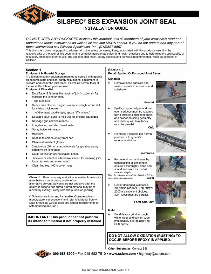
Section 1 Equipment & Material Storage In addition to safety equipment required to comply with applica-ble federal, state and local safety regulations, equipment to prepare and repair the joint faces, as well as normal tools of the trade, the following are required: Equipment Checklist:
Duct Tape (2 ½ times the length of joint)- optional– for masking the joint for drips.
Tape Measure
Heavy duty electric, plug-in, low speed– high torque drill for mixing thick epoxy
1 ½” diameter, paddle-type, epoxy “jiffy mixers”
Sausage caulk guns to hold 20o-oz silicone sausages
Sausage gun nozzles (cones)
Long-bladed, serrated bread knife
Spray bottle with water
Hacksaw
Spatula to scrape epoxy from can
Chemical-resistant gloves
2-inch wide (50mm) margin trowels for applying epoxy adhesive on joint faces
Caulk knives for tooling sealant bands
Acetone or effective alternative solvent for cleaning joint faces, trowels and mixer tools*
Clean lint-free, 100% cotton rags
Clean Up: Remove epoxy and silicone sealant from equip-ment before it cures using acetone* or alternative solvent. Solvents are not effective after the epoxy or silicone has cured. Cured material may be re-moved by cutting it away with sharp tools or grinding. (* Solvents are toxic and flammable. Observe solvent manufacturer’s precautions and refer to Material Safety Data Sheets as well as local and federal requirements for safe handling and use.)
DO NOT OPEN ANY PACKAGES or install this material until all members of your crew have read and understood these instructions as well as all relevant MSDS sheets. If you do not understand any part of these instructions call Silicone Specialties, Inc.: (918)587-5567 This document does not purport to address all of the safety concerns, if any, associated with this product’s use. It is the responsibility of the user of this document to establish appropriate safety and health practices and to determine the applicability of regulatory limitations prior to use. The use of a dust mask, safety goggles and gloves is recommended. Keep out of reach of Children.
IMPORTANT: This product cannot perform its intended function if not properly installed.
Concrete
Remove loose particles and weak concrete to ensure sound substrate.
Sawcut
Spalls, chipped edges and un-even surfaces must be repaired using suitable patching material and proper patching geometry and techniques. Joint faces must be parallel
Chip
Reinforce if needed per normal practice or Engineer’s recommendations.
Reinforce
Remove all contaminates by sandblasting or grinding to ensure a thoroughly clean and sound substrate for the full sealant depth.
Note: Do not use a wire wheel– this will polish the
substrate and cause failure Blast
Repair damaged joint faces. SILSPEC 900PNS or SILSPEC 2000 are excellent choices. Joint faces must be parallel.
Form and Pour
Metal
Sandblast or grind to rough, white metal and solvent wipe immediately prior to applying SES epoxy.
Section 2 Repair Spalled Or Damaged Joint Faces
DO NOT ALLOW OXIDATION (RUSTING) TO OCCUR BEFORE EPOXY IS APPLIED.
Other Substrates: Contact SSI
SES INSTALLATION GUIDE 3/15/15 PAGE 1 0F 7

800-888-8909 • Fax 918-582-7510 • www.ssicm.com • [email protected]
SILSPEC® and X.J.S.® are registered trademarks of Silicone Specialties, Inc.
SILSPEC® SES EXPANSION JOINT SEAL INSTALLATION GUIDE
Section 3 Correctly size the joint seal
Make sure you have the correct size material for the joint.
Measure the joint width at the deck surface and below to ensure the joint faces are paral-lel.
Material has been supplied to suit your joint widths at mean temperature based on field-measured information you provided.
Widths of material supplied are marked on each stick of material.
Compare width of material supplied as marked on each stick against mean joint width.
Actual width of material measured between the hard-board packaging will be less than the marked size be-cause material is over compressed to fit the joint.
NOTE: If unsure of correct material selection, consult SSI. IMPORTANT: Do not remove outer plastic packaging until you have read and understood the rest of these instructions as material may expand prematurely.
Section 4 How temperature affects installation
This step helps you plan your in-stallation. Temperature affects how fast or slow your SES foam expands. SES SEAL is not a lightweight, closed-cell, EVA foam– you don’t have to squeeze it to get it in the joint. SES is precompressed. When you take off the packaging, it will self expand. To figure out how fast, cut a small piece off the end of one of your sticks and take off the hardboard and plastic packaging. Measure it. Time how fast it grows to the width of the joint you just measured in step 3.
You want the material to be as big or slightly bigger than the joint gap width when you put it in. This way it will sit snug at the right level and hold it’s own weight.
When it is hot (above 80°F, 27°C) it moves fast. You want to store it in the shade or in an air conditioned van or cab. When it is COLD (below 60°F, 15°C) you have time. Some-times a lot of time. You want to store it in the sun or in a heated van or cab, AND you may want to open a few sticks ahead of installing epoxy to get them moving.
Wipe joint faces with solvent-dampened, lint-free rags to remove all concrete dust and contaminates.
Dry all wet surfaces. Do not use flame to dry substrate– this will leave carbon on the substrate and cause bond failure.
Section 5 Solvent-wipe joint faces
Changes in plane, either up or down, are easily done with the use of factory-fabricated Universal-90’s from SSI. If you ordered factory-fabricated transitions, start with these and then move on to connecting the straight lengths. (see Pages 5 and 6 for detailed instructions) If you are just installing straight lengths, go to Step 7.
Section 6 Start with Universal-90
OPTIONAL: If you want the joint to look aesthetically pleasing, use duct tape to mask off the deck on both sides of the joint.
Section 7 Mask Joint Edges (Optional)
Section 8 Mix Epoxy Adhesive
Mix Epoxy
SES epoxy adhesive may be used in the 40F to 95F (5C to 35C) temperature range.
Using a trowel, transfer the entire contents of Part B (hardener) into the contents of Part A (base).
Mix the material thoroughly for 3 minutes with a drill and mixing paddle. Scrape the walls and bottom of the container to ensure uniform and complete mixing.
Ensure that a uniform gray color with no black or white streaks is obtained.
IMPORTANT: DO NOT thin the epoxy.
BE SAFE! Wear chemical-resistant gloves and/or barrier cream when handling liquid sealant or epoxy. Remove promptly from skin with a commercial hand cleaner before eating or smoking. Avoid inhaling vapors.
SES INSTALLATION GUIDE 3/15/15 PAGE 2 0F 7

800-888-8909 • Fax 918-582-7510 • www.ssicm.com • [email protected]
SILSPEC® and X.J.S.® are registered trademarks of Silicone Specialties, Inc.
SILSPEC® SES EXPANSION JOINT SEAL INSTALLATION GUIDE
Section 9 Apply epoxy to substrate
Ensure that the mixed epoxy adhesive is applied to the substrate before the pot life has expired (10—30 minutes depending on the ambient temperature). WARNING: Epoxy will harden more quickly when left in the pot. Apply it onto the joint face as quickly as possible.
IMPORTANT: The epoxy must still be uncured when installing SES SEAL into the joint gap. If the epoxy hardens before installing the SES SEAL then reapply new epoxy. If work is interrupted more than 2 hours after initial cure then grind the old epoxy and reapply new wet epoxy. IMPORTANT: While one or more workers are applying epoxy adhesive to the joint faces, others must prepare the SES SEAL (see Step 10)
Section 10 Unwrap SES SEAL NOTE: Remember STEP 4? The SES SEAL is held in compression by shrink wrap and hardboard. Based on what you learned in STEP 4, you will either have to open several sticks to let them grow in cool weather, OR you will open them immediately before you need them in hot weather. ♦ Slit the plastic by cutting on the hardboard DO NOT cut along the silicone bellows face! If you do you will destroy the seal. ♦ Remove the shrink-wrap, hardboard and inner liner.
Section 11 Install First SES SESAL Length into Joint
When installing SES into the joint, ensure that the epoxy on the face has not cured.
When installed the SES SEAL must be recessed so that the top of the bellows in 1/2-inch (12mm) below the deck surface.
Note: When material is correctly expanded for a snug fit it will support it’s own weight in the joint.
Feed Material into joint, starting from one end. The material should fit snugly and must be eased into the joint with steady firm pressure.
Section 11 Continued:
Leave the end to be joined to
the next length sticking slightly proud of the joint.
Section 12 Apply Joining Silicone to Bellows Face
On the end of the stick, using a sausage gun and the sausages of the silicone provided, apply the liquid silicone provided, apply the liquid silicone to the exposed face of the silicone bellows.
NOTE: Avoid spreading silicone sealant on the foam face.
Section 13 Install Next Length
Work in one direction towards the previously installed length or end of the joint. Do not stretch the material.
Push, Don’t Pull
Push hard on the stick to compress joints firmly together. Ensure there are no voids at joins.
Once the full length is installed, push the protruding join into the joint and too off the excess silicone.
Make the Join Push the Join in Last
Repeat this step for each new stick.
SES INSTALLATION GUIDE 3/15/15 PAGE 3 0F 7
800-888-8909 • Fax 918-582-7510 • www.ssicm.com • [email protected]
SILSPEC® and X.J.S.® are registered trademarks of Silicone Specialties, Inc.
SILSPEC® SES EXPANSION JOINT SEAL INSTALLATION GUIDE
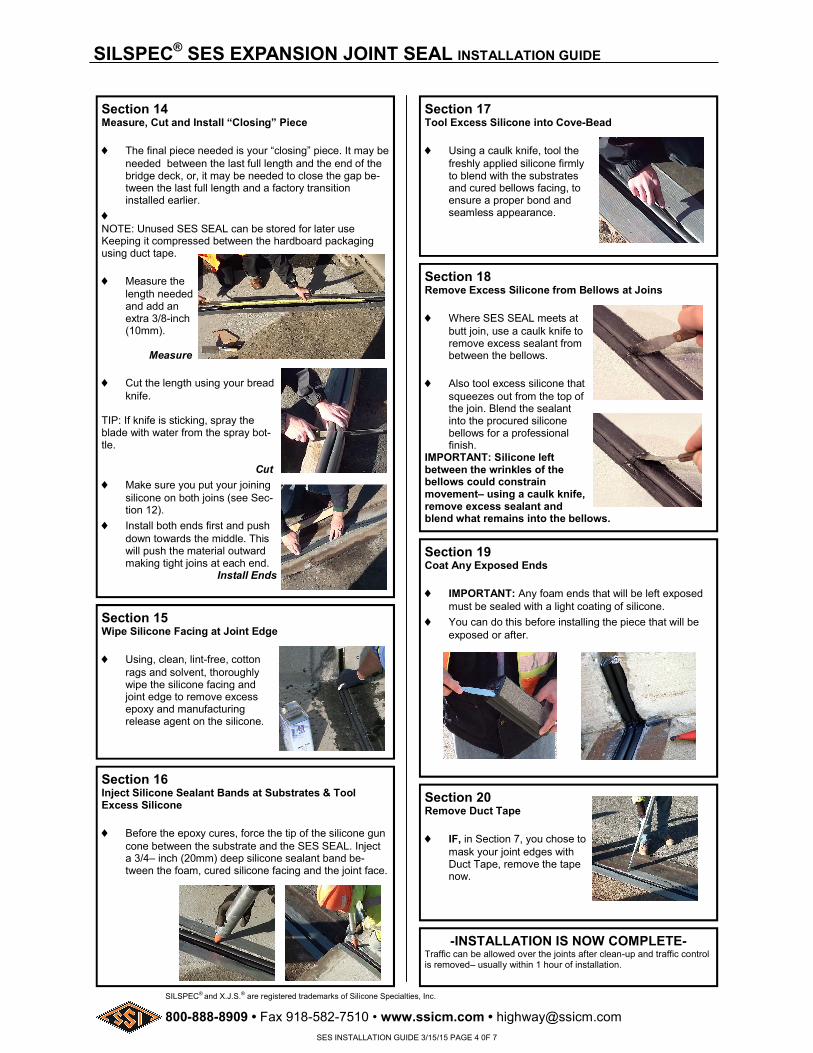
Section 14 Measure, Cut and Install “Closing” Piece
The final piece needed is your “closing” piece. It may be needed between the last full length and the end of the bridge deck, or, it may be needed to close the gap be-tween the last full length and a factory transition installed earlier.
NOTE: Unused SES SEAL can be stored for later use Keeping it compressed between the hardboard packaging using duct tape.
Measure the length needed and add an extra 3/8-inch (10mm).
Measure
Cut the length using your bread knife.
TIP: If knife is sticking, spray the blade with water from the spray bot-tle. Cut
Make sure you put your joining silicone on both joins (see Sec-tion 12).
Install both ends first and push down towards the middle. This will push the material outward making tight joins at each end. Install Ends
Section 15 Wipe Silicone Facing at Joint Edge
Using, clean, lint-free, cotton rags and solvent, thoroughly wipe the silicone facing and joint edge to remove excess epoxy and manufacturing release agent on the silicone.
Section 16 Inject Silicone Sealant Bands at Substrates & Tool Excess Silicone
Before the epoxy cures, force the tip of the silicone gun cone between the substrate and the SES SEAL. Inject a 3/4– inch (20mm) deep silicone sealant band be-tween the foam, cured silicone facing and the joint face.
Section 17 Tool Excess Silicone into Cove-Bead
Using a caulk knife, tool the freshly applied silicone firmly to blend with the substrates and cured bellows facing, to ensure a proper bond and seamless appearance.
Section 18 Remove Excess Silicone from Bellows at Joins
Where SES SEAL meets at butt join, use a caulk knife to remove excess sealant from between the bellows.
Also tool excess silicone that squeezes out from the top of the join. Blend the sealant into the procured silicone bellows for a professional finish.
IMPORTANT: Silicone left between the wrinkles of the bellows could constrain movement– using a caulk knife, remove excess sealant and blend what remains into the bellows.
Section 19 Coat Any Exposed Ends
IMPORTANT: Any foam ends that will be left exposed must be sealed with a light coating of silicone.
You can do this before installing the piece that will be exposed or after.
Section 20 Remove Duct Tape
IF, in Section 7, you chose to mask your joint edges with Duct Tape, remove the tape now.
-INSTALLATION IS NOW COMPLETE- Traffic can be allowed over the joints after clean-up and traffic control is removed– usually within 1 hour of installation.
SES INSTALLATION GUIDE 3/15/15 PAGE 4 0F 7

800-888-8909 • Fax 918-582-7510 • www.ssicm.com • [email protected]
SILSPEC® and X.J.S.® are registered trademarks of Silicone Specialties, Inc.
SILSPEC® SES EXPANSION JOINT SEAL INSTALLATION GUIDE
Addendums Staged Construction, Transitions, Ends, and Special Conditions 1) Staged Construction (Lane to Lane): (This assumes that Sections 1 thru 5 have been completed) The SES SEAL can easily be installed in Staged (Lane to Lane) Construction. If the joint does not require a change in plane at the termina-tion, simply begin the run with a straight stick at the outside end of the stage and work to the opposite end. There is no need to install a “closing” piece at this stage of the installation. At the other end of the run install the last stick to its correct depth do not leave a loose tail. Clean any epoxy adhesive off the joint faces past the end of the stick and allow it to cure. If starting at a change in plane either up or down, the use of a Universal-90 from SSI makes the transition easy: Start with the transition piece and then move on to the straight sticks. Install the straight sticks across the staged area (Lane) going from the transition piece to the other end of the run. There is no need to install a “closing” piece at this stage of the installation. At the other end of the run install the last stick to its correct depth do not leave a loose tail. Clean any epoxy adhesive off the joint faces past the end of the stick and allow it to cure. Do not allow epoxy or silicone to cure on the end of the exposed foam of the seal. Keep the end clean for the next stage of the installation. The second stage (and subsequent stages if doing more than 2 lanes) are installed in either of the following man-ners: If the end of the second stage terminates to a third stage, the straight sticks will be installed the same as the first stage stopping at the far end.
-OR- If the second stage is the end of the run terminating into a transition or change in plane. Install the transition piece first in the end of the run and install the straight sticks in between. The “closure” piece can be installed anywhere in that stage to complete the installation. Key Points to Remember:
Always start at the “outside edge” of the first stage and work inward (this can be a plane transition or straight end).
Install the last stick of the stage at the correct re-cess, do not leave a tail.
For subsequent stages always start the run on the end of the previous stage and work to the other end of the stage.
On the last stage start at the far end of the run and work back to the previous stage.
Install the “closure” piece to finish the run.
Always complete the installation of the stage including the silicone sealant bands before moving to the next stage of the installation.
Addendums 2) Sequencing: Install factory-fabricated transition and/or termination pieces first. Connect straight run material to in-place terminations and transitions. NOTE: If installing very long runs of ma-terial, to avoid having to work at distant ends of a joint run and in order to prevent epoxy from fully curing, the final factory-fabricated Universal-90 termina-tion can be installed as the second-to-the last piece. Cut closing pieces 3/8” (10mm) longer than the opening to be joined. Compress material to longitudinally fit. 3) Universal-90 Transitions Unuversal-90’s are factory-made transitions that make going up and down curbs, parapets and sidewalks easy. Unlike straight-run lengths, BOTH sides of Universal-90’s are silicone coated with bellows so there is no top or bottom. They can be turned over and used either as an upturn or downturn. 3a) Universal-90 Installation Sequence
Arrange your U-90’s at the areas that need them. Measure the height of the curb and plan to join the lower and upper U-90 in the middle of the height of the curb. Open and cut the vertical leg of the U-90 to a length that will bring it to the middle of the height of the curb. REMEMBER, the top of the SES will be recessed 1/2” (12mm) from the deck and sidewalk surface. Plan this in your measurements. Install the lower U-90 in accordance with the installation procedures in the rest of this instruction sheet. Measure to make sure the top of the SES is 1/2” (12mm) below the deck surface. Measure the distance from the top of the upturn of the installed U-90. Continued page 6
U-90 Cut closing piece 3/8” Long and “arch” into Joint.
Then press down closing piece to correct recess depth
SES INSTALLATION GUIDE 3/15/15 PAGE 5 0F 7

800-888-8909 • Fax 918-582-7510 • www.ssicm.com • [email protected]
SILSPEC® and X.J.S.® are registered trademarks of Silicone Specialties, Inc.
SILSPEC® SES EXPANSION JOINT SEAL INSTALLATION GUIDE
Addendums 3a) continued
Cut the next U-90 so that it will mate firmly with the already installed U-90. Remember to allow for the 1/2” (12mm) recess. Apply joining silicone along the edge of the silicone bellows. Lower the upper U-90 into the wet epoxy on the joint faces. Push the upper U-90 down to join firmly with the already installed U-90 upturn below. Tool the silicone that squeezes out of the join to make sure that there is no silicone in the groove in the middle. Blend the extra silicone into the bellows.
Continue installation of the straight strips starting with SECTION 12. 4) Universal-90 Terminations If you have decided to run the expansion joint material off the end of the deck instead of sealing vertically into or over a parapet, you should terminate the installa-tion with a downturn termination.
If you decide to turn the SES SEAL up into a parapet without going over the top and down the opposite side, you should terminate in the face of the parapet with an upturn termination. As with Universal-90 transitions, install factory-fabricated upturn or downturn pieces first.
Connect straight run material to in-place terminations and transitions (see STEP 12). 5) Kick-out Termination SSI’s SES “ Kick-Out Termination” is an alternative to the Universal-90 Terminations available.
Addendums The Kick-Out Termination is a factory fabricated termination piece with a built in drip-edge that directs water runoff away from the bridge structure.
The Kick-Out Termination is installed at the edge of the deck with its down-turn over the side of the bridge and the drip-edge sticking out beyond the face of the slab. Water that runs off the joint is directed away from the bridge and its bearing pads, columns ect, by the silicone coated flared end of the kick-out.
Install the Kick-Out Termination first and connect the straight lengths to it start with Step 12. 6) Field-Cut Corners When not using U-90’s it is possible to make corners in the field. Outside Corners– “Notch and Bend”
Notch the back of the foam only about 2/3 of the way through it at a 40-degree angle.
Bend the foam over keeping the silicone face intact.
Inside Corners- “Notch and Miter”
Cut the material for a horizontal joint longer than needed by an amount equal to the depth of the material being installed.
The inside corner must be joined by cutting a keyway in the horizontal material with a matching miter in the vertical material.
To cut the keyway, first make a template using a piece of the hardboard packaging and a hacksaw.
Using the template and a water-sprayed bread knife, cut each piece of foam as shown.
Install the horizontal section ensuring that the keyway is inserted past the vertical face of the joint.
Inject a bead of joining silicone into the face of the key-way and insert the vertical miter into the wet silicone. Be sure of a tight fit with no voids. Tool excess silicone to allow the bellows to move.
7) Flat Corners
Work towards the corner so that the last two pieces will join at the corner.
Cut each piece 3/8-inch (10mm) longer than needed.
Install one piece so that it runs through the intersecting joint gap. Firmly push and compress the extra length so that a tight fit in the corner is achieved.
Continued Page 7
“Kick-Out” directs water away from the structure
KEYWAY DIMENSIONS Nominal Material Size Dim. A Up to 3/4-in (20mm) 1/2-in (12mm) Over 1-in (25mm) 1-in (25mm)
Inside Corner (Section)
Outside Corner (Section)
SES INSTALLATION GUIDE 3/15/15 PAGE 6 0F 7

800-888-8909 • Fax 918-582-7510 • www.ssicm.com • [email protected]
SILSPEC® and X.J.S.® are registered trademarks of Silicone Specialties, Inc. SSI reserves the right to amend the content of this document without notice.
Warranty Limitations: SSI REPRESENTS TO THE PURCHASER OF THIS PRODUCT FROM SSI (REFERRED TO AS CUSTOMER) THAT THE INFORMATION IN THIS LITERATURE IS AN ACCURATE DESCRIPTION OF THE TYPICAL CHARACTERIS-TICS, PROPERTIES AND USES OF THE PRODUCT, IF TRANSPORTED, STORED AND APPLIED IN ACCORDANCE WITH THIS LITERATURE AND THE REFERENCED MATERIAL SAFETY DATA SHEET. UNLESS SSI PROVIDES BEFORE PRODUCT INSTALLATION AN EXPRESS WRITTEN WARRANTY AFTER RECIEPT AND EVALUATION OF SPECIFIC WRITTEN PROJECT CONDITIONS AND APPLICABLE SCOPE DOCUMENTATION, SSI’S EXCLUSIVE WARRANTY IS THAT THE PRODUCT WILL CONFORM TO THE SALES REPRESENTATIONS STATED HEREIN AND THE CURRENT MATERIAL SAFETY DATA SHEET. SSI EXPRESSLY DISCLAIMS ALL OTHER EXPRESS OR IMPLIED WARRANTIES, INCLUDING WITHOUT LIMITATION WARRANTIES OF MERCHANTABILITY AND FITNESS FOR PARTICULAR PURPOSE. IN NO EVENT SHALL SSI’S LIABILITY FOR DAMAGES ARISING FROM THE SALE OF THIS PRODUCT THE AMOUNT OF PURCHASE PRICE RECEIVED BY SSI FROM CUSTOMER FOR THIS PRODUCT DELIVERED TO THE PROJECT IN QUESTION, OR AT SSI’S SOLE OPTION, SSI MAY REPLACE THE PRODUCT OR PORTION THEREOF THAT DOES NOT CONFORM TO THE FOREGOING REPRESENTA-TION. SSI EXPRESSLY EXCLUDES ANY LIABILITY FOR SPECIAL OR CONSEQUENTIAL DAMAGES. CUSTOMER IS SOLELY RESPONSIBLE FOR EVALUATING JOB CONDITIONS AND THE SUITABILITY OF DESCRIBED PHYSICAL PROPERTIES AND CHARACTERISTICS OF THE PRODUCT TO MEET SPECIFIED OR APPARENT PROJECT REQUIREMENTS AND FOR APPLICATION OF THE PRODUCT IN ACCORDANCE WITH SSI’S RECOMMENDATIONS. THESE REPRESENTATIONS ARE INTENDED FOR RELIANCE EXCLUSIVELY BY THE CUSTOMER AND ARE NOT INTENDED TO BENEFIT ANY OTHER PERSON OR ENTITY. THESE EXCLUSIONS, MODIFICATIONS OR LIMITATIONS OF WARRAN-TIES, INCLUDING THEIR EFFECT ON RIGHTS AND REMEDIES, THAT ARE EFFECTIVE AGAINST ARE ALSO EFFECTIVE AGAINST SUBSEQUENT PURCHASERS, USERS AND THIRD PARTY BENEFICIARIES OF THE SALE OF THIS PRODUCT. SSI UNDERTAKES NO RESPONSIBILITY FOR STORAGE, MIXTURE, PREPARATION OF SURFACES, APPLICATION, USE OR MIS-USE OF PRODUCT OR ITS CONFORMITY TO SPECIFICATIONS THAT ARE NOT PREVIOUSLY AND EXPRESSLY ACKNOWLEDGED IN WRITING BY SSI.
TULSA 430 S. ROCKFORD TULSA, OK 74120 918/587-5567
OKLAHOMA CITY 610 NE 36th ST. OKLAHOMA CITY, OK 73105 405/524-9525
DALLAS 2367 GLENDA LANE DALLAS, TX 75229 972/243-0676
HOUSTON 2211 SABINE HOUSTON, TX 77007 713/862-3900
AUSTIN 13815 IMMANUEL ROAD PFLUGERVILLE, TX 78660 512/326-1156
SAN ANTONIO 2104 MANNIX SAN ANTONIO, TX 78217 210/930-6360
FT. WORTH 2545 BERNER ST. FORT WORTH, TX 76111 682/647-1881
EL PASO 7198 MERCHANT STE A-1 EL PASO, TX 79915 915/591-6800
MCALLEN 1503 MID-CITIES DRIVE PHARR, TX 78577-2128 956/782-1341
HOUSTON– BLALOCK 4400 BLALOCK ROAD SUITE 100 HOUSTON TX 77041 713/460-8800
BATON ROUGE 5813 MCCANN DRIVE BATON ROUGE, LA 70809 225/620-0950
NEW ORLEANS 300 JEFFERSON HWY BLDG 4 STE. 701 JEFFERSON, LA 70121 504/539-3102
SILSPEC® SES EXPANSION JOINT SEAL INSTALLATION GUIDE
Flat Corner continued from Page 6
Firmly butt intersecting piece(s) into side(s) of placed material.
** IMPORTANT: Be sure that there is no epoxy on the sides or faces of the foam at a butt joint.
Using a caulk knife, remove any excess sealant and blend the liquid silicone into the bellows to preserve the bellow shape.
NOTE: The extra length will make a tight fit– this results in a compression fit.
Inject a bead of liquid silicone where the silicone faces join and where the silicone the silicone faces meet the substrate.
8) Crosses and Tees
Run one piece across the intersection. Coat silicone bellows end (only) of the intersecting material with sili-cone Firmly butt intersecting pieces into sides of already placed material.
Using a caulk knife, remove any excess liquid sealant and blend the liquid silicone into the bellows to preserve the bellows shape.
9) Rehabilitating Joints with SILSPEC® Elastomeric Mortars Step 2 on page 1 refers to SILSPEC® Elastomeric Mortars as an ideal option for rebuilding or replacing failed expansion joint headers in bridges of other structures. SSI has designed these materials to offer a complete option for:
Repairing Spalled joint edges
Filling block-outs from old bolt-down plank systems
Replacing failed armor joint angles
Resizing joints that are outside limits of movement
Building headers for ACP overlay decks
Creating joint edges for new concrete decks SILSPEC® Elastomeric Mortars are supplied as complete kits including the liquid polymer binders and aggregates and are available in sizes to meet your job requirements. Silicone Specialties, Inc. offers innovative products to meet the demands of a diverse transportation market.
SSI Transportation Products Include:
SILSPEC® 900PNS/XJS JOINT SYSTEM SILSPEC® 900 POLYMER NOSING SYSTEM (PNS) is a two-component rapid curing liquid polymer that cures to a dense, semi-flexible, weather, abrasion and impact resistant polymer mortar for the construction or repair of expansion and construction joints on bridge and parking decks. The combined polymer is mixed with SILSPEC® BLENDED AGGREGATE to form a polymer based mortar for nosing or joint repair. When used in conjunction with Dow Corning 902 RCS Silicone Sealant, it provides an alternative for strip seals, compression seals, and elastomeric devices in new bridge deck expansion joints; and results in substantially improved performance at lower cost.
SILSPEC 2000® POLYMER NOSING SYSTEM SILSPEC® 2000 is a flexible, two-component rapid curing urethane liquid polymer that cures to a dense, semi-flexible, weather, abrasion and impact resistant polymer mortar. It is used for the con-struction or repair of expansion and construction joints on bridge decks, concrete pavements and parking decks. The SILSPEC® 2000 liquid component is mixed with Silspec® Blended Aggregate to form a polymer based concrete for nosing's or joint/pavement repairs.
SILSPEC® FLEXPATCH SILSPEC® FLEXPATCH is a three-component, 100% solids, multi-purpose, high-strength, non-shrink, waterproof, non-conductive, semi-flexible polymer patching mortar for longer lasting patches with excellent workability. The system combines a high quality polymer resin and curing agent with SILSPEC® BLENDED AGGREGATE. Repair of delaminations and potholes on bridges, roadways, airport runways, parking and garage decks. SILSPEC® FLEXPATCH is also used to repair joint edge spalls and corner-breaks on pavements. SILSPEC® FLEXPATCH conforms to ACPA Bulletin TB003P for use in partial depth pavement repairs.
SILSPEC® RE-DECK SILSPEC® RE-DECK is a solvent free, moisture tolerant, low viscosity epoxy/urethane binder and adhesive meeting the requirements of ASTM C-881, Type III, Grade I, Classes B & C. SILSPEC® RE-DECK is used primarily for bonding skid-resistant overlays and high friction surfaces to bridges and elevated slabs and as a low modulus binder for epoxy mortars where thermal change is a consideration. The material can also be used to seal interior and exterior above grade slabs and as a low modulus crack filler.
SILSPEC® DECKSEAL SILSPEC® DECKSEAL is a 75% solids highly penetrating, two compo-nent epoxy healer/sealer which when applied to cracked bridge decks or elevated concrete, will structurally seals the cracks against moisture and chloride ion intrusion. DECKSEAL can be used on: Bridge decks Parking decks Floors Columns and beams in splash zone areas Consolidation of porous & dusting floors
SES INSTALLATION GUIDE 3/15/15 PAGE 7 0F 7