Embed Size (px)
Citation preview

Service ManualTrucks
Group 177–501
Preventive MaintenanceAnnual Service
VN,VHD
PV776-TSP158779

Foreword
The descriptions and service procedures contained in this manual are based on de-signs and methods studies carried out up to January 2002.
The products are under continuous development. Vehicles and components producedafter the above date may therefore have different specifications and repair methods.When this is believed to have a significant bearing on this manual, supplementary ser-vice bulletins will be issued to cover the changes.
The new edition of this manual will update the changes.
In service procedures where the title incorporates an operation number, this is a refer-ence to an S.R.T. (Standard Repair Time).
Service procedures which do not include an operation number in the title are for gen-eral information and no reference is made to an S.R.T.
The following levels of observations, cautions and warnings are used in this ServiceDocumentation:
Note: Indicates a procedure, practice, or condition that must be followed in order tohave the vehicle or component function in the manner intended.
Caution: Indicates an unsafe practice where damage to the product could occur.
Warning: Indicates an unsafe practice where personal injury or severe damage to theproduct could occur.
Danger: Indicates an unsafe practice where serious personal injury or death could oc-cur.
Volvo Trucks North America, Inc.Greensboro, NC USA
Order number: PV776-TSP158779
© 2002 Volvo Trucks North America, Inc., Greensboro, NC USA
All rights reserved. No part of this publication may be reproduced, stored inretrieval system, or transmitted in any forms by any means, electronic, me-chanical, photocopying, recording or otherwise, without the prior writtenpermission of Volvo Trucks North America, Inc..
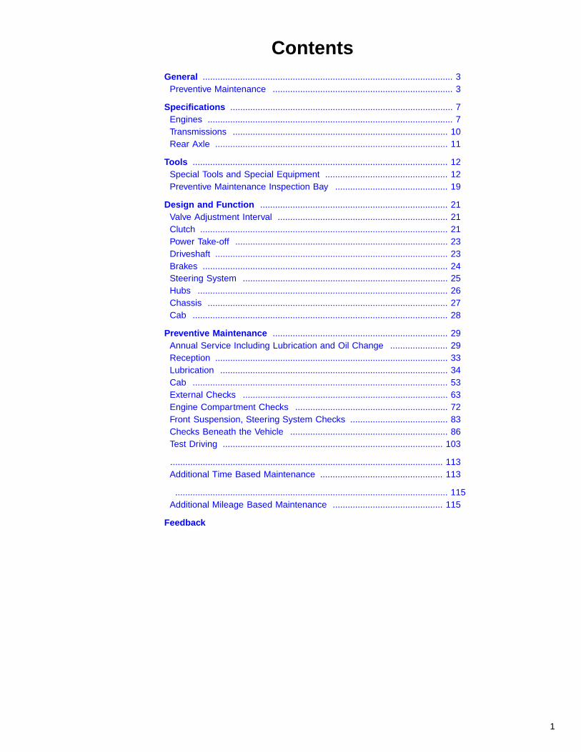
ContentsGeneral .................................................................................................... 3
Preventive Maintenance ........................................................................ 3
Specifications ......................................................................................... 7Engines .................................................................................................. 7Transmissions ...................................................................................... 10Rear Axle ............................................................................................. 11
Tools ...................................................................................................... 12Special Tools and Special Equipment ................................................. 12Preventive Maintenance Inspection Bay ............................................. 19
Design and Function ........................................................................... 21Valve Adjustment Interval .................................................................... 21Clutch ................................................................................................... 21Power Take-off ..................................................................................... 23Driveshaft ............................................................................................. 23Brakes .................................................................................................. 24Steering System .................................................................................. 25Hubs .................................................................................................... 26Chassis ................................................................................................ 27Cab ...................................................................................................... 28
Preventive Maintenance ...................................................................... 29Annual Service Including Lubrication and Oil Change ....................... 29Reception ............................................................................................. 33Lubrication ........................................................................................... 34Cab ...................................................................................................... 53External Checks .................................................................................. 63Engine Compartment Checks ............................................................. 72Front Suspension, Steering System Checks ....................................... 83Checks Beneath the Vehicle ............................................................... 86Test Driving ........................................................................................ 103
............................................................................................................. 113Additional Time Based Maintenance ................................................. 113
............................................................................................................. 115Additional Mileage Based Maintenance ............................................ 115
Feedback
1

2

Group 177 General
GeneralPreventive Maintenance
W9000073
Introduction
This manual describes inspection and lubrication re-quirements during the Annual Service of Volvo vehicles.The purpose for performing the preventive maintenanceis to ensure that the vehicle is safe and roadworthy overits full lifetime.
The driver is taking part in the continuous preventivemaintenance program by completing the required DailyPre-trip Inspection. This is a purely visual inspection thatis designed to detect any obvious problems that wouldmake the vehicle unsafe to take on the road. Added tothe Pre-trip Inspection is the Preventive MaintenanceProgram that is typically carried out by trained personnelusing a systematic approach to cover all important com-ponents of the new vehicle.
Preventive maintenance is a planned vehicle mainte-nance program that provides an orderly series ofservicing and inspecting procedures. A well appliedmaintenance program realizes the investment made inthe vehicle. The difference between a poorly maintainedvehicle and a well maintained vehicle will not show upuntil later mileages. Good maintenance is necessary toassure the designed life expectancy of the vehicle andits individual components.
Maintenance Coverage
There is no firm maintenance program that will apply toall operations. A basic maintenance program is not diffi-cult to set up; to make the program the most effectivetakes time and effort, and is based around the needsand experiences of each individual operation. The pro-gram in this service manual covers all types of VolvoVN/VHD vehicles with medium to high mileages andsometimes high loads.
Use this established maintenance program as a base totailor an individual maintenance program for customersthat have requirements that are outside of the scope ofthis program.
To establish an individual program, look at informationsources that are usually available, such as:
Driver’s repair or complaint reports.Unusual parts usage.Repetitive failures or problems found in inspection.Unscheduled maintenance or repairs.Road failures.
3
Group 177 General
Program Structure
This maintenance program has been based on theprogress in vehicle technology and increases in oil qual-ity to simplify the maintenance.
For simplified scheduling, the program has tied mainte-nance to logical time or mileage limits that make it easyto anticipate needed servicing. For the majority of on-highway operators, the 24,000 km (15,000 miles) or 4months schedule can be used with little change.
It is important that the scheduled intervals are followedas limits. Maintenance can be done before either 24,000km (15,000 miles) have been reached or before 4months are up but must be made at or before either themileage or the time limit has been reached.
Advantages
A well-planned preventive maintenance program offersthe following advantages:
The lowest attainable maintenance cost.
Maximum vehicle uptime.
Better fuel economy.
Reduced road failures; greater dependability.
Increased customer confidence, better public rela-tions.
Less possibility of accidents due to defective equip-ment.
Fewer driver complaints.
Regardless of the planning and the details of the mainte-nance program, the success of the program hinges onthe caliber of workmanship in performing the actualinspection. A major cause of failure is a “pencil inspec-tion”; that is, the mechanic checks off each operation asbeing OK without making the actual inspection. A “pencilinspection” defeats the purpose of the inspection, whichis to detect an impending failure.
Maintenance Form
A service manual is issued detailing the current inspec-tion forms. Forms are created for different users but allwith the same references to this document. When the in-spection point is carried out, check the box if the item isOK. If further work, such as adjustment, repair, etc.,needs to be performed, check that box and go on withthe next inspection point. Items noted as being faulty orin need of adjustment need to be shown to the customerand scheduled for repair.
There are many time — and/or mileage-based — ser-vice items that are not listed on the form. Look at theend of this document for a listing of additional compo-nents that may need to be serviced, depending on themileage or time since last service.
Maintenance Records
It is important to use the inspection form together withother reports to come up with the best maintenance pro-gram for a specific application. Use driver’s reports,complaints, parts usage, repetitive failures, previous re-pair orders, road failures, etc. to build a maintenancepicture of the customer operation.
Records should be collected over the lifetime of the vehi-cle to form a permanent vehicle record file. The vehiclefile should be used to customize the operational mainte-nance needs.
The “Driver Inspection Form” is also required by Federallaw. The use of this inspection report makes the driver apart of the maintenance program and places direct re-sponsibility on the driver to report problems that maycome up during operation. When properly used, thereshould be no excuse for a defective vehicle being in ser-vice.
Note: The included Annual Service checklist is anuncontrolled copy. The document may be updatedwithout notice.
Annual Inspection
Note: For further information refer to Publication 177-500, “Preventive Maintenance, Basic Service, VN,VHD.”
The Annual inspection is carried out yearly in addition toa Basic inspection. This inspection is designed to openup components for inspection or using test equipment torecord performance.
The ideal time to carry out the Annual inspection is rightbefore the hardest season, which means just before win-ter in the cold weather climates or just before summer inthe hot weather climates.
All inspection points are to be carried out as verificationof function or condition. Any defects are noted on the in-spection form for later correction, if so ordered by thevehicle owner.
Note: The standard repair time for performing theAnnual Service Preventive Maintenance is based oninspection without repair or adjustment, and Oil andFilter Change.
4

Group 177 General
Other Inspection
There are additional service points that are carried out atspecific mileage or time intervals. These are not part ofthe Preventive Maintenance basic time. They should bescheduled as an adjustment or repair job carried out atthe same time as the Preventive Maintenance, and arelisted in this document as reminders only.
Noise EmissionsVolvo Trucks North America, Inc. warrants to the firstperson who purchases this vehicle for purposes otherthan resale and to each subsequent purchaser, that thisvehicle as manufactured by Volvo Trucks North America,Inc. was designed, built and equipped to conform, withall applicable U.S. EPA Noise Control Regulations, at thetime it left the control of Volvo Trucks North America, Inc.
This warranty covers this vehicle as designed, built andequipped by Volvo Trucks North America, Inc., and is notlimited to any particular part, component or system ofthe vehicle manufactured by Volvo Trucks North Amer-ica, Inc. Defects in design, assembly or in any part,component or system of the vehicle as manufactured byVolvo Trucks North America, Inc., which, at the time itleft the control of Volvo Trucks North America, Inc.caused noise emissions to exceed Federal standards,are covered by this warranty for the life of the vehicle.
Tampering with Noise Control System
Federal law prohibits the following acts or the causingthereof:
(1) The removal or rendering inoperative by any person,other than for purposes of maintenance, repair, orreplacement, of any device or element of design incorpo-rated into any new vehicle for the purpose of noisecontrol prior to its sale or delivery to the ultimate pur-chaser or while it is in use;
or
(2) the use of the vehicle after such device or element ofdesign has been removed or rendered inoperative byany person.
Among those acts presumed to constitute tampering arethe acts listed below:
Noise Shields and Insulation
Removing or rendering inoperative the engine and/ortransmission noise deadening panels, shields or insulat-ing materials.
Removing or rendering inoperative the cab tunnel orhood noise insulating materials.
Removing or rendering inoperative any truck bodymounted sound insulation components and/or shields(e.g., cab or fender shields, skirts, wheel housing splashshields, etc.).
Engine Control and Fuel Systems
Removing or rendering inoperative, or modifying the en-gine control system (such a the ECU or the fuel systemcomponents) in order to allow the engine to operate out-side of the manufacturer’s specifications (e.g., exceedingthe manufacturer’s engine speed limits).
Cooling System
Removing or rendering inoperative cooling system com-ponents (e.g., temperature-controlled fan clutch, fanshroud, fan ring, recirculation shields, etc.).
Exhaust System
Removing or rendering inoperative exhaust system com-ponents (e.g., muffler, pipes, clamps, etc.).
Air Intake System
Removing or rendering inoperative air intake/inductionsystem components (e.g., filter, filter housing, ducts,etc.).
5

Group 177 General
Safety Advice
Never operate a diesel engine in an area where hy-drocarbon vapors (gasoline for example) are presentor are suspected to be present. Hydrocarbon vaporscan enter the air intake and make the engine over-speed, causing severe damage and/or explosion orfire. Serious personal injury or death can occur.
Before working on a vehicle, set the parking brakes,place the transmission in neutral, and block thewheels. Failure to do so can result in unexpectedvehicle movement and can cause serious personal in-jury or death.
When entering and exiting the cab, use caution. Al-ways have a firm hand hold and/or stable foot positionbefore transferring weight to that position. Do notcarry anything when entering or exiting. Make surethe soles of your shoes and the cab steps are freefrom dirt, grease, oil or moisture before using thesteps. Failure to do so can result in a fall, and seriouspersonal injury or death may occur.
If using a jack and/or jack stands, choose properfault-free equipment. Failure to do so can result inequipment failures and personal injury or death mayoccur.
Note: During the Preventive Maintenance inspection,check the condition of warning labels on the vehicle. If alabel is damaged or defaced to the point where the mes-sage cannot be read, note on the inspection form tohave it replaced.
6

Group 177 Specifications
Specifications
EnginesGeneral
For further information concerning component specifica-tions see service information in Group 1, “Oil and FilterChange Intervals for Volvo Components,” PublicationNumber 175–001, and appropriate vendor literature.
In a modern diesel engine it is very important to haveregular oil changes. The demands of pulling high loads,pulling at high elevations, extreme high or low tempera-tures and longer service intervals, make the choice ofcorrect oil a hard task. The Volvo dealer, the enginemanufacturer or the oil manufacturer has the expertise toanalyze driving conditions and to recommend which oilgives the best protection and economy.
Oil
The engine oil lubricates, seals, cools and cleans the en-gine. Filtering the intake air and using a low sulfur fuelhelps the oil protect the engine parts. With better enginedesigns and improved oils, the service intervals havesteadily increased. The interval choice depends on theengine manufacturer specifications. Make sure the cor-rect oil type and also the correct viscosity are chosen forthe mileage interval driven.
Periodic oil testing is recommended. The test resultsgive a continuous picture of the health of the engine andcan warn well in advance of a problem developing.
The intervals will not cover all applications. In on/offhighway driving, severe off highway, continuous stop-and-go city driving and extremely high mileages, the oilchange interval and preventive maintenance scheduleneed to be customized for the best protection and econ-omy. The intervals listed in these specifications areguidelines that should be used in establishing a correctmaintenance program.
CAUTION
Adding unknown additives may put the engine at riskof failure. There are many aftermarket oil additivesthat claim improved performance if added to the en-gine oil. Each oil type recommended already containsadditives that have been tested by a collaboration withengine and oil manufacturers.
Synthetic oil is offered as an alternative to the traditionalpetroleum based oil for the engines. The ability of syn-thetic oil to protect the engine is better than regular oilbut its life is the same as for regular oil. This is becauseof the combustion by-products that contaminate the oil.These contaminates will make the change intervals the
same as for regular oil. However, in extreme driving con-ditions, a synthetic oil may be the only choice for theapplication.
Note: It is not recommended to mix synthetic oils withpetroleum-based oils.
Coolant
The engine coolant protects the cooling system fromfreezing or boil over problems. It also protects againstcorrosion and cylinder liner pitting. Coolant requirementsare based on the additive levels present in the coolingsystem. To be able to run the cooling system as long as2 years between coolant changes, there must be a re-plenishment of additives as they are used up. Testingshould be done regularly to be sure the additive levelsare within recommended levels.
Never run the engine with only water in the coolingsystem. Always use a mixture of clean water and a rec-ommended antifreeze. The mixture should never be lessthan 40% antifreeze and 60% clean water or more than60% antifreeze and 40% clean water.
Texaco Extended Life Coolant
Note: For further information on long life coolant refer toService Bulletin 260–002, “Texaco Extended LifeCoolant.”
CAUTION
Texaco Long life coolant is colored red for identifica-tion purposes, so as not to mistake it for conventional,green coolant. Long life coolant will test as out of ad-ditives (SCA), but SCA should not be added.
Fleetgaurd ES Complete Long Life Coolant
Note: For further information on Fleetgaurd ES CompleteLong Life Coolant refer to appropriate vendor literature.
Fuel
The sulfur content in low-sulfur fuel has been regulatedto a maximum of 0.05% per weight for No.2–D dieselfuel. For fuels that have a sulfur content of 0.5% byweight and above, most engine manufacturers are re-quiring that oil is changed at shorter intervals. Sulfurcreates highly acidic pollutants in the oil that break downthe additives at a higher rate. If fuel with a higher sulfurcontent is used, the engine manufacturers recommendthat the oil change intervals be reduced.
7

Group 177 Specifications
VOLVO ENGINESNote: It is not recommended to mix synthetic oils withpetroleum based oils.
For further information concerning component specifica-tions see service information in Group 1, “Oil and FilterChange Intervals for Volvo Components,” publicationnumber 175-001, and appropriate vendor literature.
Maximum change intervals are 40,000 km (25,000 miles)if using oil that meets the Volvo Drain Specification -2(VDS -2) . If the oil does not meet the requirements ac-cording to VDS, change intervals should be 24,000 km(15,000 miles) or less. Contact Volvo or a Volvo autho-rized dealer to obtain a list of approved VDS oils.
Shorter oil change intervals maybe required if the engineis operating in a dusty environment or if frequent stopsand starts are made.
Supplemental coolant additives are recommended for allVolvo cooling systems. Antifreeze alone does not providesufficient corrosion protection for heavy duty diesel en-gines.
If the fuel has a sulfur content exceeding 0.5% byweight, halve the indicated maximum mileage intervals.
Oil filters should always be changed when changing oil.
CUMMINS ENGINESFor further information, refer to the appropriate vendorliterature.
If the engine is operating in ambient temperatures con-sistently below - 20 �C (0 �F) or above 40 �C (100 �F),perform maintenance at shorter intervals. Shorter inter-vals are also required if the engine is operating in a dustyenvironment or if frequent stops and starts are made.
Oil filters should always be changed when changing oil.
Supplemental coolant additives are recommended for allCummins cooling systems. Antifreeze alone does notprovide sufficient corrosion protection for heavy dutydiesel engines.
Maximum Oil Drain Intervals
Note: Extended oil drain intervals are not recommended.
8
Group 177 Specifications
DETROIT DIESEL ENGINESFor further information, refer to the appropriate vendorliterature.
The use of fuels with a sulfur content above 0.5% byweight will require more frequent oil changes. Refer toDetroit Diesel Publications for details. More frequent oilchanges are also required if the engine is operating in adusty environment or if frequent stops and starts aremade.
Oil filters should always be changed when changing oil.
Supplemental coolant additives are recommended for allDetroit Diesel cooling systems. Antifreeze alone doesnot provide sufficient corrosion protection for heavy dutydiesel engines.
Note: The Detroit Diesel Engine is installed in earlier VNvehicles (from 1996–2001) only.
CATERPILLAR ENGINESFor further information, refer to the appropriate vendorliterature.
Caterpillar does NOT recommend an automatic exten-sion of oil drain intervals with high quality oil, low sulfurfuel and non-severe duty driving. Oil drain intervals canonly be extended with an oil analysis program containingthe following elements: oil condition and wear metals,trend analysis, fuel consumption and oil consumption.
In areas where fuel sulfur content exceeds 1.5%, choosean oil with a total base number that is within the APICF-4 or CG-4 categories and shorten the oil change pe-riod based on oil analysis.
Shorter oil change intervals are required if the engine isoperating in a dusty environment or if frequent stops andstarts are made (see oil change interval below).
Oil filters should always be changed when changing oil.
Supplemental coolant additives are recommended for allCaterpillar cooling systems. Antifreeze alone does notprovide sufficient corrosion protection for heavy dutydiesel engines.
Note: Caterpillar Engines were installed in earlier VN ve-hicles (from 1996–1999) only.
9

Group 177 Specifications
Transmissions
Includes Volvo, Eaton Fuller, Meritor, and Allison HD TransmissionsFor further information concerning component specifications see service information inGroup 1, “Oil and Filter Change Intervals for Volvo Components,” publication number175-001, and appropriate vendor literature.
10

Group 177 Specifications
Rear Axle
Includes Volvo, Arvin Meritor, and Eaton Dana Rear AxlesFor further information concerning component specifications see service information inGroup 1, “Oil and Filter Change Intervals for Volvo Components,” publication number175-001, and appropriate vendor literature.
11

Group 177 Tools
ToolsSpecial Tools and Special Equipment
The following special tools are recommended for use in the preventive maintenance in-spection. Special tools can be ordered through the Volvo Special Tools program in theparts ordering system or directly from Kent-Moore by calling (800) 328–6657. (Kent-Moore tool numbers are preceded by a J.) Please refer the specific tool number whenordering.
Special Tools
W0001489
W0001198
J-42942ABS Sensor Adjustment Tool(Kent-Moore)
J-42189Airline Release Tool(Kent-Moore)
W0001731
W0001874
J-44399Air System Tester
J-44773Airline Release Tool
W0001896
W5001199
J-44769Wheel Speed Sensor Extractor
J-44966Wheel Speed Sensor Remover for Heavy Duty Steer Axleand Aluminum Hub
12

Group 177 Tools
J-44302A/C Schrader Valve Core Removal Tool
J-44338Oil Dipstick for A/C Compressor
J-22610Drive Shaft Boot Camp Pliers
J-43143Tie Strap Tensioner
J-41610Feeler Gauge Set
J-44392Fan Belt Tensioner Tool
13

Group 177 Tools
PT 5900Chip Vacuum
9998142Charge Air Cooler Pressure Tester
J-38641-BDiesel Fuel Hydrometer
14

Group 177 Tools
Other Special Equipment
W0001261
W3000642
J-42397-ACoolant Pressure Test Adapter
1089953Bulb Removal Tool
J-23600-BBelt Tension Gauge
W7000708
W0001985
J-38460-ADigital Inclinometer
J-36795Tandem Axle Calipers
W0001843
W0001207
3093472Timken Wheel End Play Gauge
9996791Spring Pin Socket
15

Group 177 Tools
9998691Oil Filter Nipple Installer Kit
3947553, 3949521, 3946522, 3949523Terminal and Shim Kits
J-44701Battery Tester Kit
J-44778, J-44779Driveshaft U-Joint and Yoke Kits
16

Group 177 Tools
VCADS Pro ToolsThe following hardware is used to operate VCADS Pro. The tools can be ordered fromVolvo Trucks North America; please refer to the specific tool number when ordering.
W5001142
C0000285
7
1 PC tool-package
2 9998555, Communication interface unit
3 9812331, Extension cable
4 J-43999, 6 pin Diagnostic adapter (for vehicles priorto 1999)
5 J-43939, 9 pin Diagnostic adapter (for vehicles builtfrom January 1999)
6 9998496, Pressure gauge
7 9998495, Air Pressure Hose
17

Group 177 Tools
Lighting System, Special ToolsThe tools listed below are used to complete maintenance on the Lighting System forVolvo Trucks. They may be obtained from Volvo, or where indicated, from Kent Mooreat (800) 328-6657.
J-25300-DHeadlight Aiming Kit (Kent Moore)
1089953Lamp Removal Tool (Volvo)
J-42395Rheostat Removal Tool (Kent Moore)
20378326Fuse Puller Tool (Volvo)
J-43244Relay Puller Tool (Kent Moore)
18
Group 177 Tools
Preventive Maintenance Inspection Bay
LocationPreventive maintenance is logically carried out at thesame time as lubrication of the vehicle. It is then naturalto use a bay with a grease pit to be assigned andequipped for preventive maintenance. If a pit is not avail-able, a regular workshop bay can be used, with jacksadded to the necessary equipment.
The bay needs to be well lit so inspection can be donewithout having to use a flashlight (unless inspecting inthe frame).
EquipmentInspection bay equipment should be specifically as-signed to that bay and not be shared with the rest of theshop. The floor equipment should have floor space forstorage in between using them and tools should be hungon boards or stored in a cabinet for easy overview andaccess.
Install mirrors in four corners of the bay so one personcan do a lighting function check without having to leavethe cab or rely on a spotter. Mirrors do not need to belarger than truck door mirrors. Any type of equipmentthat allows inspection by one person instead of having touse a helper, makes inspection easier and faster.
19

20
Group 177 Design and Function
Design and Function
Valve Adjustment IntervalCheck the engine valve clearance after the first sixmonths of operation. Check every 12 months thereafter.Adjust if necessary.
For information on valve clearance check and adjust-ment refer to Service Information, Group 2.
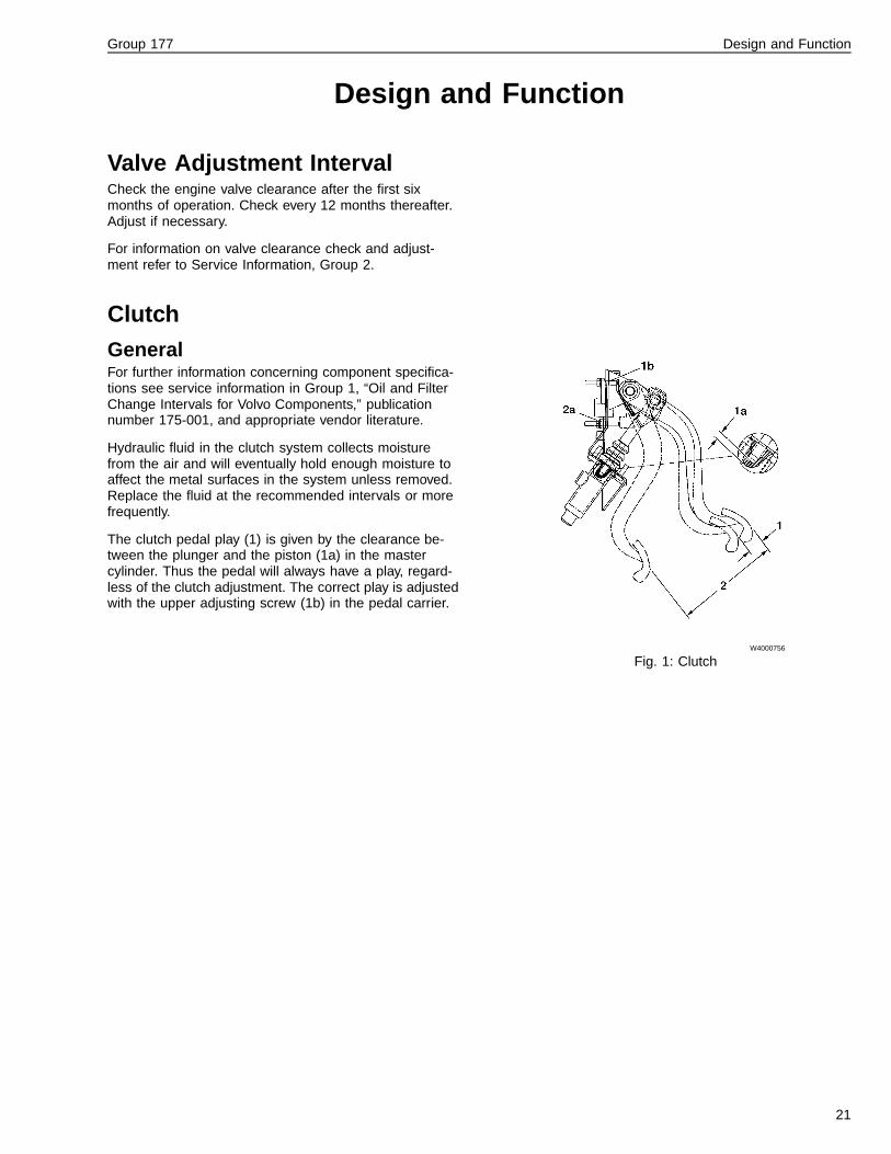
Clutch
GeneralFor further information concerning component specifica-tions see service information in Group 1, “Oil and FilterChange Intervals for Volvo Components,” publicationnumber 175-001, and appropriate vendor literature.
Hydraulic fluid in the clutch system collects moisturefrom the air and will eventually hold enough moisture toaffect the metal surfaces in the system unless removed.Replace the fluid at the recommended intervals or morefrequently.
The clutch pedal play (1) is given by the clearance be-tween the plunger and the piston (1a) in the mastercylinder. Thus the pedal will always have a play, regard-less of the clutch adjustment. The correct play is adjustedwith the upper adjusting screw (1b) in the pedal carrier.
W4000756
Fig. 1: Clutch
21

Group 177 Design and Function
Volvo Clutch Slave CylinderSlave cylinder stroke (A) is 29 ± 1 mm (1.14 ± 0.04 in.).The clutch pedal throw (2 — see previous illustration)gives the stroke. The lower adjusting screw (2a) limits thepedal throw and thereby the clutch slave cylinder stroke.
Distance B should never be exceeded. The distance isadjusted by removing the fork from the lever and reposi-tion lever on the cross shaft.
Distance C is set when the clutch is new. During wear ofclutch, the distance will decrease. Readjustment shouldnot be needed before it is time to reface the clutch disc.
W4000731
Fig. 2: Volvo Clutch Slave Cylinder
Other Clutch Slave CylinderA slave cylinder for any non-Volvo clutch has a wear in-dicator. When the indicator is out of the operating range,it is time to adjust the clutch.
To get the slave cylinder throw into the accepted range,adjust the clutch plate until the indicator is in the operat-ing range again.
W4002441
1 Slave Cylinder
2 Mounting Bolts
3 Clutch Clevis Pin
4 Clutch Master Cylinder and Reservoir (Foundon the Bulkhead in the Engine Coupling)
22

Group 177 Design and Function
Power Take-off
Volvo PTOFor further information concerning component specifica-tions see service information in Group 1, “Oil and FilterChange Intervals for Volvo Components,” publicationnumber 175-001, and appropriate vendor literature.
Volvo PTO’s mount directly to the transmission and donot need separate oil fill and check. Make sure there isextra oil filled in the transmission for the PTO volume.
CAUTION
Transmission oil heat exchanger should be installedwhen using PTO continuously over 15 minutes at atime or with a continuous power output over 55 kW(75 hp). Without heat exchanger, the oil can overheatand transmission damage may follow.
If the application has a remotely installed pump or blowerwith a driveshaft connection, the driveshaft U-joints needto be greased at every maintenance interval or more of-ten, depending on usage. Use a lithium-based greasewith EP additives and of the consistency of NLGI No. 2.
W4000758
Driveshaft
Failure to correctly grease the driveshaft U-joints orslip-joints can lead to component failure which can re-sult in separation of the driveshaft from the vehicle. Aseparated driveshaft can result in major componentdamage and loss of vehicle control, and can causeserious personal injury or death.
For further information concerning component specifica-tions see service information in Group 1, “Oil and FilterChange Intervals for Volvo Components,” publicationnumber 175-001, and appropriate vendor literature.
Use a lithium-based grease with EP additives with aconsistency of NLGI No. 2. Do not use conventionalchassis grease.
The driveshaft U-joints must be lubricated correctly forthe bearings to receive grease. The most common caseof U-joint failure is incorrect greasing. Always make surethat grease is coming out of all four seals. If one sealfails to purge old grease, move the driveshaft from sideto side while applying gun pressure. This allows forgreater clearance on the thrust end of the bearing that isnot purging. New grease flushes abrasive contaminantsfrom each bearing and assures that the bearing is filledproperly.
W4000753
23

Group 177 Design and Function
Brakes
Brake Cams and Slack AdjustersFor further information concerning component specifica-tions see service information in Group 1, “Oil and FilterChange Intervals for Volvo Components,” publicationnumber 175-001, and appropriate vendor literature.
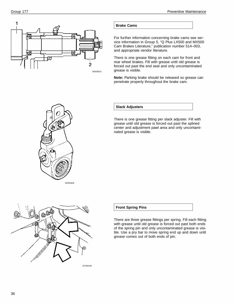
For further information concerning brake cams see ser-vice information in Group 5, “Q Plus LX500 and MX500Cam Brakes Literature,” publication number 514–003,and appropriate vendor literature.
Lubricate the brake cam bushings using a lithium-basedgrease with EP additives and consistency NLGI No. 2.Fill grease until old grease has been pushed out pastthe seal and new grease can be seen flowing.
Lubricate the slack adjusters using a lithium-basedgrease with EP additives and consistency NLGI No. 2.Fill grease until old grease has been pushed out pastthe splined shaft area, and adjustment pawl and newgrease can be seen flowing.
W5000615
Air DryersAir dryers have internal maintenance systems that cleanout the accumulated moisture frequently and can there-fore work with long maintenance intervals. Eventually thedrying medium will be filled up and the cartridge willneed to be changed. Change cartridge when there ismore water being drained in the daily emptying of thetank than usual. This is a progressive development andthe time interval will be different from application to ap-plication.
Dryer manufacturers recommend changing cartridge ev-ery 2 to 3 years but intervals need to be adjusted forapplication. The only dryer with regular maintenance isthe Midland, where the coalescent filter needs changingevery year.
Note: If a vehicle is operated in a severe weather envi-ronment, It is recommended to change the air dryercartridge prior to the severe weather season.
W5001194
24

Group 177 Design and Function
Steering System
Steering Linkage and KnucklesFor further information concerning component specifica-tions see service information in Group 1, “Oil and FilterChange Intervals for Volvo Components,” publicationnumber 175-001, and appropriate vendor literature.
For axle forward models, grease the steering shaft U-joints every 4 months. A more frequent maintenanceinterval may be required if the vehicle is operated undersevere driving conditions.
W6000869
25
Group 177 Design and Function
Steering SystemFor further information concerning component specifica-tions see service information in Group 1, “Oil and FilterChange Intervals for Volvo Components,” publicationnumber 175-001, and appropriate vendor literature.
Use Automatic Transmission Fluid (ATF) Dexron® II orDexron® III for the steering system.
A darkened fluid indicates a steering system that is run-ning hotter than normal and the fluid is overheated.Troubleshoot the reason for overheating and changefluid.
W6000868
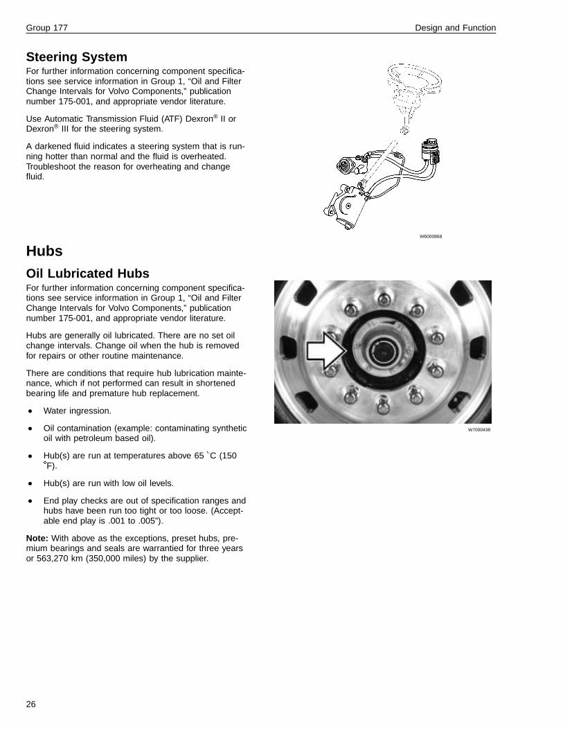
Hubs
Oil Lubricated HubsFor further information concerning component specifica-tions see service information in Group 1, “Oil and FilterChange Intervals for Volvo Components,” publicationnumber 175-001, and appropriate vendor literature.
Hubs are generally oil lubricated. There are no set oilchange intervals. Change oil when the hub is removedfor repairs or other routine maintenance.
There are conditions that require hub lubrication mainte-nance, which if not performed can result in shortenedbearing life and premature hub replacement.
• Water ingression.
• Oil contamination (example: contaminating syntheticoil with petroleum based oil).
• Hub(s) are run at temperatures above 65 �C (150�F).
• Hub(s) are run with low oil levels.
• End play checks are out of specification ranges andhubs have been run too tight or too loose. (Accept-able end play is .001 to .005”).
Note: With above as the exceptions, preset hubs, pre-mium bearings and seals are warrantied for three yearsor 563,270 km (350,000 miles) by the supplier.
W7000438
26

Group 177 Design and Function
Chassis
Springs and SuspensionFor further information concerning component specifica-tions see service information in Group 1, “Oil and FilterChange Intervals for Volvo Components,” publicationnumber 175-001, and appropriate vendor literature.
Lubricate spring pins using a lithium-based grease withEP additives and the consistency of NLG1 No.2. Fillgrease until old grease has been pushed out past theseal on both sides and new grease can be seen flowing.If grease is not flowing through, use a prybar to leverdown the spring ends to open up for the grease to flow.To perform this procedure the axle must be free hanging.Refer to the Service Information in Group 7.
Wear tolerance for the spring pin and bushing is 5 mm(3/16 in.). W7000449
27

Group 177 Design and Function
T-Ride Equalizer BeamFor further information concerning component specifica-tions see service information in Group 1, “Oil and FilterChange Intervals for Volvo Components,” publicationnumber 175-001, and appropriate vendor literature.
In regular over-the-road operations the T-Ride shouldfollow the normal lubrication schedule.
It is extremely important that the equalizer beam is welllubricated in any off-road or on/off-road operation. Ifthere are other severe duty constraints, for example driv-ing in water, lubricate more frequently, up to once perday, if necessary.
For further information on the T-Ride Equalizer Beam,refer to 721–600, “Rear Suspension, T-Ride.” W6000838
Cab
DoorsDoor lock mechanism should be greased once per yearusing white lithium grease. Coat the door stop armwith grease every year.
W8000949
HoodHood lock lever (front latch) is coated with teflon andshould not need any conventional lubrication. If themechanism is working hard or binds, try cleaning first.Clean and lubricate the scissor latch at the base conereceptacle with white grease.
W8000888
28

Group 177 Preventive Maintenance
Preventive MaintenanceAnnual Service Including Lu-brication and Oil ChangeDate: Model: Reg. No.:
Time: Vehicle Identification Number: Engine:
Dealer Code: Transmission
Name: Rear Axle:
X = Corrected without comment √ Correction not needed N = Not relevant or applicable
Lubrication, Oil and Fluid Level Check
1 Chassis Lubrication
2 Cab Lubrication
3 Change Engine Oil and Filter
4 Check Oil Level in Manual Transmission
5 Check Oil Level in Automatic Transmission
6 Check Oil Level in PTO, Power Take-Off
7 Check Oil Level in Retarder
8 Check Oil Level in Transfer Case
9 Check Oil Level in Front Drive Axle
10 Check Oil Level in Rear Drive Axle
11 Check Oil Level in Hydraulic Bogie Lift
12 Check Oil Level in Power Steering
13 Check Oil Level in Hubs for Oil Lubricated WheelBearings
14 Check Oil Level in Cab Tilt Pump
15 Check Fluid Level in Clutch Fluid Reservoir
16 Check Coolant Freeze Protection and CoolantLevel
17 Check Fluid Levels in Windshield Wiper andHeadlamp Wiper Reservoirs
18 Check Air Dryer
Checks in Cab
19 Check Warning and Control Lamps
20 Check Fault Codes in the Vehicle ElectronicControl Unit
Checks in Cab
21 Check Fault Codes in the Engine ElectronicControl Unit
22 Check Fault Codes in the ABS, Anti-Lock Brakes
23 Check Fault Codes in Transmission
24 Function Check of Parking Heater
25 Check Engine Control in Cab
26 Check Retarder Control
27 Start Engine and Check of Starter Element andPreheater
28 Check Pressure Regulator’s Disconnection andConnection Pressure
29 Check Air Compressor’s Function and Condition
30 Check Sealing on Main Brake Circuit (Service)
31 Check Parking Brake and Blocking Valve
32 Check Gearshift and Clutch Pedal
33 Check Bogie Lift
34 Check Brake Pedal and Foot Brake Valve
35 Check Hinges, Doorstops, Locks and SealingStrips
29

Group 177 Preventive Maintenance
External Checks
36 Function Check of External Lamps
37 Check Rear View Mirrors and Reflectors
38 Function Check of Wipers and Washers
39 Check Headlamps
40 Check Air Filter for Ventilation System
41 Check Refrigerant Reservoir, Condenser, Pipesand Hoses
42 Check Air Intake and Air Deflector
43 Check Hood Attachment and Locking Devices
44 Check Batteries - Dirt, Leakage, Attachment,Specific Gravity of Battery Acid, Fluid Level, Con-nections and Battery Box
45 Check Fuel Tank, Hoses, Pipes, Venting andMounting
46 Check Filter for Fuel Tank Ventilation
47 Draining of Fuel Tank (Dirt, Water)
48 Check Fuel Water Separator for the Fuel System,Draining of Condensation
49 Check Tire Wear
Engine Compartment
50 Check Alternator Mounting
51 Check Electrical Connections and Cables for Al-ternator, Starter Motor and Preheater
52 Check Drive Belts
53 Check Air Compressor
54 Check Engine Mounting
55 Check Radiator Mounting
56 Check Radiator Fan, Bearing Tolerance, BoltUnions, Fan Cover and Fan Ring with Rubber Seal
57 Pressure Testing of Cooling System
58 Check Radiator, Hoses, Pipes and Air Flow
59 Check Intercooler, Hoses, Pipes and Air Flow
60 Check Tightness of Engine and PTO
61 Check Fuel Lines on Engine
62 Check Exhaust Leakage
63 Check A/C Compressor Mounting
64 Check A/C Pipes and Hoses
65 Check Air Pipe between Air Intake and Turbo
66 Check Turbocharger and Regulator
67 Check Pump Coupling for Injection Pump (Elec-tronic Engines Not Applicable)
Engine Compartment
68 Check Tightness on Servo Pump, Oil Lines andSteering Gear
69 Check Sound Baffles for Engine
Front Suspension, Steering System Check
70 Check Steering Linkage
71 Check Front Shock Absorbers
72 Check Steering Knuckle Bearing
73 Check Front Wheel Bearings
74 Check Front Wheels
Checks Beneath the Vehicle
75 Check Tightness, Bearing Clearance and Ventila-tion on the Front Driving Axle
76 Check Clearance in Clutch’s Mechanical Function
77 Check Clutch’s Hydraulic and Pneumatic ControlSystem
78 Check Clutch Wear
79 Check Transmission’s Pneumatic and MechanicalControl System
80 Check Seals for Speedometer Sensor and JointCoupling
81 Check Tightness on Transmission, Transfer Caseand PTO Including check of lines
82 Check Tightness on Cooler for Transmission
83 Check Ventilation for Transmission, Transfer Caseand PTO
84 Check Tightness on Retarder and check lines
85 Check Sound Baffle for Gearbox
86 Check Transfer Case’s Mounting
87 Check Drive Belt for Power Steering
88 Check Drive Shaft Universal Joints, Sliding Jointsand Support Bearings
89 Check Tightness on Rear Drive Axles and HubReduction Gear
90 Check Bearing Clearance for Pinion and InputShaft to Rear Drive Axles
91 Check Rear Drive Axle Ventilation
92 Check Exhaust Pipe and Silencer
93 Check Rear Springs and U Bolts
94 Check Anti-Roll Bar
95 Check Rear Shock Absorbers
96 Check Mounting for Front and Rear Axle
30

Group 177 Preventive Maintenance
Checks Beneath the Vehicle
97 Check Bogie Lift or Lift Axle
98 Check Rear Suspension Level Sensors and Level-ing Valves
99 Check Height Regulation for Air Suspension
100 Check Chassis Frame and Crossmembers
101 Check Central Lubrication System
102 Check Compressed Air Lines and Hoses
103 Check Rear Wheel Bearings
104 Check Rear Wheels
105 Check Differential Locks
106 Check Brake Linings
107 Check Brake Cylinders, Levers, and Forks
Checks Beneath the Vehicle
108 Check Brake Disc and Brake Calipers
109 Check Stroke Length on Slack Adjusters, BrakeLevers, and Brake Drums
110 Check Load Sensing Valve
111 Check Brake Chambers and Mounting Brackets
Test Driving
112 Check After Start
113 Check During Test Driving
114 Check After Test Driving
115 Finish
31

Group 177 Preventive Maintenance
Note: The values seen from cab and backwards are noted in the squares below
RightBrake Linings - measuredthickness in mm (in.)
Left
RightBrake Levers, Slack Ad-justers, and Brake Drums -measured stroke in mm (in.)
Left
Notes on wear pattern ontires
Right
Left
T1006800
Comments
32

Group 177 Preventive Maintenance
Reception
W1000068
When the customer drops off the vehicle, the service re-ceptionist starts the paperwork and prepares the formsneeded for the preventive maintenance. Ask the cus-tomer about problems that have been noticed whiledriving the vehicle. Ask questions that will make the jobeasier for the technician to find problem sources:
— Irregular tire wear?
— Unusual noise?
— Unusual vibration?
— Leaks?
— Other operation problems?
As the vehicle is approached, check for signs of leakage,general appearance, body damage, etc. Walk around thevehicle. Note on the PM inspection form if any leaks orproblems are found.
33

Group 177 Preventive Maintenance
LubricationMake sure that grease fittings are cleaned off before fill-ing grease. Dirt on the fitting that is not cleaned off ispushed into the part with the new grease. Always fillgrease to the point where old grease and contaminantsare forced out from the part and only new grease comesout. If grease can not be filled so old grease is forcedout or if new grease exits without pushing old greaseout, note this on the form for repair. If a fitting does not
accept lubrication due to damage or internal stoppage,replace with a new fitting.
Do not heat part for better grease application where rub-ber or plastic parts are involved.
Remove excess grease from fittings, spring shackles andother surfaces.
W1000161
34

Group 177 Preventive Maintenance
W6000848
1 Chassis Lubrication
Note: Chassis lubrication should be performed everyfour months including the annual lubrication.
Front Axle Steering Knuckles
Volvo: Two grease fittings on each side-one on the topknuckle cover (fill with grease until the old grease isforced out past the top seal), one on the bottom cover(fill with grease until the old grease is forced out past thebottom seal).
Note: Lubrication of the Volvo axle should be done withthe wheels on the ground!
W6000850
Front Axle Steering Knuckles
Meritor and Eaton: Raise the axle so the wheels are offthe ground before attempting to grease the steeringknuckles.Two grease fittings on each side-one on the top knucklecover, fill with grease until the old grease is forced outpast the top seal; one on the bottom cover, fill withgrease until the old grease is forced out past the bottomseal.
W6000869
Steering Linkage
Steering shaft and draglink are lubed for life. Tie-rod forVolvo front axles are lubed for life.
Meritor and Eaton front axle tie-rods need to lubricated.Fill tie-rod end with grease until old grease is forced outpast the rubber boot and only uncontaminated grease isvisible.
35
Group 177 Preventive Maintenance
W5000615
Brake Cams
For further information concerning brake cams see ser-vice information in Group 5, “Q Plus LX500 and MX500Cam Brakes Literature,” publication number 514–003,and appropriate vendor literature.
There is one grease fitting on each cam for front andrear wheel brakes. Fill with grease until old grease isforced out past the end seal and only uncontaminatedgrease is visible.
Note: Parking brake should be released so grease canpenetrate properly throughout the brake cam.
W5000609
Slack Adjusters
There is one grease fitting per slack adjuster. Fill withgrease until old grease is forced out past the splinedcenter and adjustment pawl area and only uncontami-nated grease is visible.
W7000449
Front Spring Pins
There are three grease fittings per spring. Fill each fittingwith grease until old grease is forced out past both endsof the spring pin and only uncontaminated grease is visi-ble. Use a pry bar to move spring end up and down untilgrease comes out of both ends of pin.
36
Group 177 Preventive Maintenance
W4000771
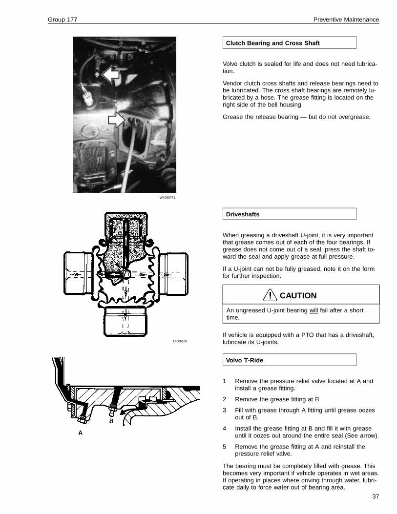
Clutch Bearing and Cross Shaft
Volvo clutch is sealed for life and does not need lubrica-tion.
Vendor clutch cross shafts and release bearings need tobe lubricated. The cross shaft bearings are remotely lu-bricated by a hose. The grease fitting is located on theright side of the bell housing.
Grease the release bearing — but do not overgrease.
T4006100
Driveshafts
When greasing a driveshaft U-joint, it is very importantthat grease comes out of each of the four bearings. Ifgrease does not come out of a seal, press the shaft to-ward the seal and apply grease at full pressure.
If a U-joint can not be fully greased, note it on the formfor further inspection.
CAUTION
An ungreased U-joint bearing will fail after a shorttime.
If vehicle is equipped with a PTO that has a driveshaft,lubricate its U-joints.
Volvo T-Ride
1 Remove the pressure relief valve located at A andinstall a grease fitting.
2 Remove the grease fitting at B
3 Fill with grease through A fitting until grease oozesout of B.
4 Install the grease fitting at B and fill it with greaseuntil it oozes out around the entire seal (See arrow).
5 Remove the grease fitting at A and reinstall thepressure relief valve.
The bearing must be completely filled with grease. Thisbecomes very important if vehicle operates in wet areas.If operating in places where driving through water, lubri-cate daily to force water out of bearing area.
37

Group 177 Preventive Maintenance
W9000074
2 Cab Lubrication
Fifth Wheel
Note: For further information refer to “Cab” page 28.
Lubricate the plate pivot points and slide mechanism.Apply a heavy coat of grease on top of the plate.
W8000949
Lubricate Door Locks
Hood lock lever (front latch) is coated with teflon andshould not need any conventional lubrication. If themechanism is working hard or binds, try cleaning first.Clean and lubricate the scissor latch at the basecone receptacle with white lithium grease once peryear.
W6000843
Steering Gear
TRW and Sheppard steering gears may have severeweather seals at input shaft or sector shaft that requiregreasing.
CAUTION
Lubricate with a hand grease gun only. High-pressuregrease application may unseat or damage seal.
38

Group 177 Preventive Maintenance
T1006392
A Oil Plug
B Oil Filter
T2012858
1 Reducing valve
2 Overflow valve for oil filters (By-pass)
3 Oil valve for pistons cooling
4 Overflow valve for oil filters (By-pass)
5 Thermostatic valve
6 Safety valve
3 Change Engine and Oil Filter
For further information concerning component specifica-tions see service information in Group 1, “Oil and FilterChange Intervals for Volvo Components,” publicationnumber 175-001, and appropriate vendor literature.
Change engine oil and filters. If required by customer,take a sample of the oil for analysis.
Note: Make sure the oil type is correct and has the cor-rect viscosity. The two are not the same and are equallyimportant in giving the right protection for the engine.
Oil Change
Before working on a vehicle, set the parking brakes,place the transmission in neutral, and block thewheels. Failure to do so can result in unexpectedvehicle movement and can cause serious personal in-jury or death.
WARNING
Take precautions when draining the oil. Wear glovesand let the engine cool down before draining. Seriousburns can result from contact with a hot engine or hotengine oil.
WARNING
Use rubber gloves when handling used oil. Wash skinthoroughly if it comes in contact with used oil. Pro-longed contact with used engine oil may be harmful.
It is important to drain as much oil as possible. Try tochange oil immediately after driving, when the oil iswarm. Always replace the oil filters when changing oil.
Note: Always dispose of oil according to Federal and lo-cal regulations. Used oil disposed of inappropriately cancontaminate nature, waterways, community drinking wa-ter and kills wildlife.
39

Group 177 Preventive Maintenance
W2003480
D12 Oil Filters
W2003078
D7 Oil Filters
1 Full-flow Filter
2 Bypass Filter
Oil Filters
CAUTION
Use only the engine manufacturer’s oil filter for re-placement. Use of an oil filter not built to specificationcould result in severe damage to bearings, crankshaft,etc. as a result of unfiltered oil entering the lubricationsystem.
Note: Always dispose of oil according to Federal and lo-cal regulations. Used oil disposed of inappropriately cancontaminate nature, waterways, community drinking wa-ter and kills wildlife.
Install new filters as follows:
• Coat the filter gasket with oil.• Install the filter and turn it by hand until the gasket
makes contact with the sealing surface.• Then turn the filter an additional 3/4 turn.
Oil Level CheckNote: Do not let the oil level drop below the lower mark-ing on the dipstick. Do not overfill so the level is abovethe upper marking on the dipstick.
Wait five minutes after shutting off the engine beforechecking the oil level. This gives the oil time to drainback to the oil pan.
40

Group 177 Preventive Maintenance
W4000768
4 Check Oil Level In Manual Transmission
For further information concerning component specifica-tions see service information in Group 1, “Oil and FilterChange Intervals for Volvo Components,” publicationnumber 175-001, and appropriate vendor literature.
Note: Synthetic oil is not recommended for the Volvotransmissions.
Volvo:
Perform the first oil and filter change at 10,000 km(6,000 miles). See specifications for regular oil andfilter change intervals. Ensure that the filter cover issecure after changing the filter.
Fuller:
Petroleum based oil: Perform the first oil and filterchange at 5,000 to 8,000 km (3,000 to 5,000 miles).See specifications for regular oil and filter changeintervals.
Synthetic lubricant: No initial oil change is neces-sary. See specifications for the regular oil and filterchange intervals.
Meritor:
Petroleum based oil: Perform the first oil and filterchange at 5,000 to 8,000 km (3,000 to 5,000 miles).See specifications for regular oil and filter changeintervals.
Synthetic lubricant: No initial oil change is neces-sary. See specifications for the regular oil and filterchange intervals.
41

Group 177 Preventive Maintenance
W4002517
5 Check Oil Level in Automatic Transmission
Note: For further information refer to “Transmissions”page 10.
Transmission fluid cools, lubricates, and transmits hy-draulic power. Always maintain proper fluid level. If fluidlevel is too low, the torque converter and clutches do notreceive an adequate supply of fluid and the transmissionoverheats. If the level is too high, the fluid aerates caus-ing the transmission to shift erratically and overheat.Fluid may be expelled through the breather or dipsticktube when the fluid level is too high.
Transmission fluid check:
1 Clean all dirt from around the end of the fluid filltube before removing the dipstick. Do not allow dirtor foreign matter to enter the transmission. Dirt orforeign matter in the hydraulic system may causeundue wear of transmission parts, make valvesstick, and clog passages. Check the fluid level usingthe following procedure and record the level in yourmaintenance log.
2 Always check the fluid level reading with the enginerunning at least twice. Consistency is important tomaintaining accuracy of the reading. If inconsistentreadings persist, check the transmission breather tobe sure it is clean and unclogged.
42
Group 177 Preventive Maintenance
Cold Check:
Note: The fluid level rises as its temperature rises. Donot fill above the Cold Run band if the transmission fluidis below normal operating temperatures.
1 The purpose of the cold check is to determine if thetransmission has enough fluid to be operated safelyuntil a hot check can be made.
2 Run the engine for at least one minute. Apply ser-vice brake. Shift to Drive (D) and operate the enginefor 30 seconds at 1000 to 1500 rpm; then shift toReverse (R) to clear the hydraulic system of air.Then shift to Neutral (N) and allow the engine to idle(500 to 800 rpm).
3 With the engine running, remove the dipstick fromthe tube and wipe clean.
4 Insert the dipstick into the tube and remove. Checkthe fluid level reading. Repeat the check procedureto verify reading.
5 If the fluid level is within the “COLD RUN” band, thetransmission may be operated until the fluid is hotenough to perform a “HOT RUN” check. If the fluidlevel is not within the “COLD RUN” band, add ordrain as necessary to bring it to the middle of the“COLD RUN” band.
6 Perform a hot check at the first opportunity after thenormal operating temperature of 71 - 93 �C (160 -200 �F) is reached.
43

Group 177 Preventive Maintenance
Hot Check:
Note: The fluid must be hot to insure an accurate check.The fluid level rises as the temperature increases.
1 Operate the transmission in Drive (D) range untilnormal operating temperature is reached:
• sump temperature 71 - 93 �C (160 - 200 �F)
• converter-out temperature 82 - 104 �C (180 -220 �F)
2 Park the vehicle on a level surface and shift to Neu-tral (N). Apply the parking brake and chock thewheels. Allow the engine to idle (500 - 800 rpm).
3 With the engine running, remove the dipstick fromthe tube and wipe clean. Insert the dipstick into thetube and remove.
4 Check the fluid level reading. Repeat the check pro-cedure to verify the reading.
5 If the fluid level is not within the “HOT RUN” band,add or drain as necessary to bring the fluid level towithin the “HOT RUN” band.
44
Group 177 Preventive Maintenance
W4000758
W4002393
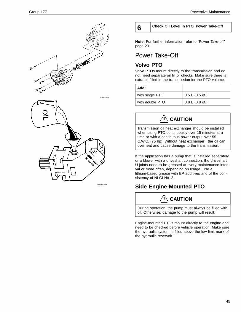
6 Check Oil Level in PTO, Power Take-Off
Note: For further information refer to “Power Take-off”page 23.
Power Take-Off
Volvo PTOVolvo PTOs mount directly to the transmission and donot need separate oil fill or checks. Make sure there isextra oil filled in the transmission for the PTO volume.
Add:
with single PTO 0.5 L (0.5 qt.)
with double PTO 0.8 L (0.8 qt.)
CAUTION
Transmission oil heat exchanger should be installedwhen using PTO continuously over 15 minutes at atime or with a continuous power output over 55C.W.O. (75 hp). Without heat exchanger , the oil canoverheat and cause damage to the transmission.
If the application has a pump that is installed separatelyor a blower with a driveshaft connection, the driveshaftU-joints need to be greased at every maintenance inter-val or more often, depending on usage. Use alithium-based grease with EP additives and of the con-sistency of NLGI No. 2.
Side Engine-Mounted PTO
CAUTION
During operation, the pump must always be filled withoil. Otherwise, damage to the pump will result.
Engine-mounted PTOs mount directly to the engine andneed to be checked before vehicle operation. Make surethe hydraulic system is filled above the low limit mark ofthe hydraulic reservoir.
45

Group 177 Preventive Maintenance
T1006646
1 Level/Fill Plug
2 Drain Plug
7 Check Oil Level in Retarder
To ensure the correct oil level in the retarder the oil levelshould be checked when the retarder is warm.
8 Check Oil Level in Transfer Case
Not applicable for VN/VHD vehicles.
46

Group 177 Preventive Maintenance
T0008128
1 Level/Fill Plug
2 Drain Plug
T0008164
1 Level/Fill Plug
2 Drain Plug
W4000768
9 Check Oil Level in Front Drive Axle
Note: For further information refer to “Driveshaft” page23.
Checking and Draining Oil
WARNING
Take precautions when draining the oil. Wear glovesand let the engine cool down before draining. Seriousburns can result from contact with a hot engine or hotengine oil.
Check the oil level through the top plug. The oil shouldbe level with the hole. Add oil if necessary.
Drain oil through the bottom plug. Drain oil immediatelyafter driving the vehicle, so that the oil is hot.
Note: Also check the rear axle ventilation for blockage.Blockage can cause extreme pressure in the axle andcreate leaks.
Hub ReductionFor further information concerning component specifica-tions see service information in Group 1, “Oil and FilterChange Intervals for Volvo Components,” publicationnumber 175-001, and appropriate vendor literature.
If the axle is equipped with hub reduction, empty eachhub separately when changing oil. Turn the wheel untilthe drain plug is at it’s lowest position. Remove plug anddrain.
Fill oil through the level/fill plug hole. Fill each hub reduc-tion before filling oil in the rear axle
Note: Synthetic oil is not recommended for the Volvotransmissions.
47

Group 177 Preventive Maintenance
T0008128
1 Level/Fill Plug
2 Drain Plug
T0008164
1 Level/Fill Plug
2 Drain Plug
W4000768
10 Check Oil Level in Rear Drive Axle
Note: For further information refer to “Rear Axle” page11.
Checking and Draining Oil
WARNING
Wear protective gloves and glasses when changingoil. Hot oil can cause severe burns.
Check the oil level through the top plug. The oil shouldbe level with the hole. Add oil if necessary.
Drain oil through the bottom plug. Drain oil immediatelyafter driving the vehicle, so that the oil is hot.
Note: Also check the rear axle ventilation for blockage.Blockage can cause extreme pressure in the axle andcreate leaks.
Hub ReductionFor further information concerning component specifica-tions see service information in Group 1, “Oil and FilterChange Intervals for Volvo Components,” publicationnumber 175-001, and appropriate vendor literature.
If the axle is equipped with hub reduction, empty eachhub separately when changing oil. Turn the wheel untilthe drain plug is at it’s lowest position. Remove plug anddrain.
Fill oil through the level/fill plug hole. Fill each hub reduc-tion before filling oil in the rear axle
Note: Synthetic oil is not recommended for the Volvotransmissions.
Note: Independent shift units require an lubricationcheck, independent of the axle lubrication check.
48

Group 177 Preventive Maintenance
T1006404
A Drain Plug
B Filler Plug
11 Check Oil Level in Hydraulic Bogie Lift
This option not available on VN/VHD vehicles.
W6001428
12 Check Oil Level in Power Steering
For further information concerning component specifica-tions see service information in Group 1, “Oil and FilterChange Intervals for Volvo Components,” publicationnumber 175-001, and appropriate vendor literature.
The power steering fluid reservoir contains AutomaticTransmission Fluid (ATF) Dexron® III.
If the fluid has darkened, then that indicates that thepower steering system is running hotter than normal andoverheating the fluid. Report the problem to and servicethe vehicle at a Volvo Truck Dealer.
49

Group 177 Preventive Maintenance
W7000438
13 Check Oil Level in Hubs for Oil LubricatedWheel Bearings
Note: For further information refer to “Hubs” page 26.
Front Wheel Hubs
Failure to keep wheel bearings properly adjusted canresult in accelerated tire wear, poor handling, and inextreme cases, wheel separation from the hub or fromthe spindle resulting in loss of vehicle control and se-rious personal injury or death.
The front wheel hubs are lubricated with several types ofoil. The suggested types are SAE 30 or 15W40. It is ac-ceptable to use either synthetic or petroleum based oils(Synthetic oils are not recommended for Volvo Axles).Axle oils API GL-5 and SAE 75W-90 are acceptable aswell.
Hubs are generally oil lubricated. There are no set oilchange intervals. Change oil when the hub is removedfor repairs or other routine maintenance.
T1006749
A Fill Plug
14 Check Oil Level in Cab Tilt Pump
This option not available on VN/VHD vehicles.
50
Group 177 Preventive Maintenance
W4000749
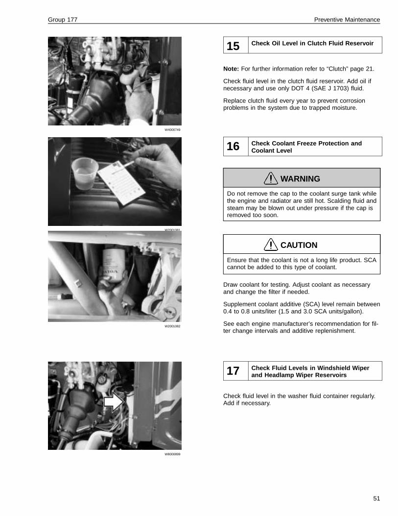
15 Check Oil Level in Clutch Fluid Reservoir
Note: For further information refer to “Clutch” page 21.
Check fluid level in the clutch fluid reservoir. Add oil ifnecessary and use only DOT 4 (SAE J 1703) fluid.
Replace clutch fluid every year to prevent corrosionproblems in the system due to trapped moisture.
W2001081
W2001082
16 Check Coolant Freeze Protection andCoolant Level
WARNING
Do not remove the cap to the coolant surge tank whilethe engine and radiator are still hot. Scalding fluid andsteam may be blown out under pressure if the cap isremoved too soon.
CAUTION
Ensure that the coolant is not a long life product. SCAcannot be added to this type of coolant.
Draw coolant for testing. Adjust coolant as necessaryand change the filter if needed.
Supplement coolant additive (SCA) level remain between0.4 to 0.8 units/liter (1.5 and 3.0 SCA units/gallon).
See each engine manufacturer’s recommendation for fil-ter change intervals and additive replenishment.
W8000899
17 Check Fluid Levels in Windshield Wiperand Headlamp Wiper Reservoirs
Check fluid level in the washer fluid container regularly.Add if necessary.
51

Group 177 Preventive Maintenance
W5001194
18 Check Air Dryer
Air DryersAir Dryers have internal maintenance systems that cleanout the accumulated moisture frequently and can there-fore work with long maintenance intervals. Eventually thedrying medium fills up and needs replacement. Changethe cartridge when the medium is filling up more thanusual. This service rate varies upon the application.
Dryer manufacturers recommended changing cartridgeevery two to three years but intervals vary per applica-tion. The only dryer with regular maintenance is theMidland, which requires changing of the coalescent fil-ters every year.
52

Group 177 Preventive Maintenance
Cab
W3000639
W3000628
W3000881
19 Check Warning and Control Lamps
Check all indicators on the instrument cluster. Turn theignition on. Wait until the instrument has gone throughthe start-up cycle. Press the MODE button until the diag-nostic window shows DIAGNOSTICS MENU. Press theDOWN button twice and the SET button once. The diag-nostic window reads BULB TEST?. Press SET and theinternal check program lights up all indicators. If any bulbis not functioning note it on the checklist.
Press the DOWN and SET buttons once and the checkprogram tests the buzzer functions. Three different dura-tions of the tone are heard.
Press down the SET buttons again and the check pro-gram tests the gauges. Most gauges go to half range,full range and then back to rest three times.
Press the DOWN and SET button again for testing thediagnostic display. The display alternates between lightand dark. If any defects are noted cite them on thechecklist. Return the diagnostic display to the clock bypressing the MODE button five times.
To perform the ABS “chuff-test,” turn the ignition off.Press down the foot brake and then turn the ignition backon again. Listen through the side window that the ABSself-check goes through the cycle twice. Each pass oper-ates the ABS modulator valves once, which results in abrief puff of air being released from each valve. The ABSindicator turns on and off twice and then remains on.
Note: For vehicles with the Traction Control System(TCS) five ’chuffs’ occur for each valve.
If the vehicle is equipped with a Volvo engine, the enginepreheater indicator stays on three to four seconds. If thecoolant temperature is over 50 �C (120 �F), the preheateris not engaged. If the coolant temperature is below 50�C (120 �F), the preheater progressively engages longerdepending on the coldness of the coolant. If the indicatorstays on, there is a problem in the preheater circuit.
53

Group 177 Preventive Maintenance
W2002673
20 Check for Fault Codes in the Vehicle Elec-tronic Control Unit
The instruments, vehicle ECUs and engine ECUs, arealways included in the system. Other included controlunits depend on the vehicle variant, legal requirements,and the vehicle specifications.
The control units are:
• Driver information display
• Instrument
• Vehicle ECU
• Engine ECU
• ABS Control Unit
• EBS Control Unit
• Air Suspension Control Unit
• Retarder Control Unit
• Load Indicator Control Unit
• Air Bag Control Unit
• Anti-Theft Control Unit
Ensure the engine is switched off during the servicecheck and the starter key is in the drive position (I).
The control lever on the right-hand side of the wheel isused to communicate and read off any fault codes onthe instrument’s driver information display.
1 Read any fault codes by using the control lever anddisplay. These fault codes are saved in the vehicle’scontrol units.
2 Write down and fault codes displayed and then cor-rect the faults.
3 After correction, zero out the fault codes.
Fault codes can be read also with a diagnosis outputPC. This instrument is placed underneath the instrumentpanel on the driver’s side of the vehicle.
54

Group 177 Preventive Maintenance
T2006602
Engine ECU
21 Check for Fault Codes in the Engine Elec-tronic Control Unit
Use Service Information in Function Group 23 as a refer-ence.
When reading fault codes perform the following:
• The engine is off.
• The parking brake is applied.
• The starter key is in the drive position (I).
1 Read on the display that no fault codes are saved inthe EECU.
2 Press the diagnosis button for four seconds.
3 “CHECK ENGINE” lamp shines steadily for threeseconds after the starter key is turned to the driveposition (I).
4 Write down any fault codes.
Fault codes can be read via diagnosis output using a PC.
W5001348
1 Toothed Hub or Tooth Wheel2 Sensor3 ECU4 ABS Valve5 Relay Valve6 TCS Valve7 J1922/J1939 Connector
22 Check for Fault Codes in the ABS, Anti-Lock brakes
Note: Use Service Information in Function Group 59 asa reference.
To complete the Fault Code Check for ABS, perform thefollowing:
1 Check that no fault codes are saved in the ABSECU.
2 Write down any fault codes require correction.
Note: Fault codes can also be traced using a diagnosticprogram run through a PC.
55

Group 177 Preventive Maintenance
W4002407
23 Check for Fault Codes in Transmission
Note: Use Service Information in Function Group 40 asa reference.
To complete the Fault Code Check for Transmission per-form the following:
1 Check that no fault codes for the Transmission aresaved in the Vehicle ECU.
2 Write down any fault codes require correction.
Note: Fault codes can also be traced using a diagnosticprogram run through a PC.
W8001006
1 Utility Outlet
2 Option Switches
3 Clock
4 Alarm Switch
5 Fan Control
6 Temperature Control
7 Lighter
24 Function Check of Parking Heater
Check the heater and ensure that the exhaust is notblocked or leaking. Fumes from the exhaust cancause personal injury or death.
If the vehicle is equipped with a parking heater, start thevehicle and run the parking heater for fifteen minutes toperform a function check.
Note: Do not stop the parking heater until it has been al-lowed to run fifteen minutes or the function check will beinaccurate.
Note and correct any faults.
56

Group 177 Preventive Maintenance
W3000815
25 Check Engine Control in Cab
Check engine controls and performance while movingthrough the gears. Accelerator pedal should worksmoothly and without any hesitation in engine response.Engine should accelerate smoothly and without hesita-tion, misses or surges. Also, check the exhaust throughthe mirrors for excessive smoke during acceleration.
During acceleration in a low gear, let engine go to fullspeed on a flat stretch of road. Note maximum enginespeed. Check the engine manufacturer’s specificationsfor correct speed.
T0008215
26 Check Retarder Control
Ensure that the steps of the retarder control are well-defined and that the control stops in the set position.
57

Group 177 Preventive Maintenance
W3000829
W3000881
27 Start Engine and Check of Starter Elementand Preheater
Starter Motor
Using an ammeter, test starter motor for maximum cur-rent draw. Check service manual for specifications.
Inspect mounting for secureness and for possible cracksaround flanges.
Check wires for wear, fraying, and terminal tightness.
Make sure the wiring is properly routed and securelyclamped.
Volvo Engine Preheater
Inspect the Volvo engine preheater for correct function.
The ignition switch has a position in between the normalrun position and the start position that engages the pre-heater. The engagement time is dependent on enginecoolant temperature:Above 10 �C (50 �F) — engagement time: 0 seconds.Between 10 to −15 �C (50 to 4 �F) — engagementtime: 25 ± 2 to 55 ± 2 seconds.Below −15 �C (4 �F) — engagement time: 55 seconds.
Note: The preheat engages independent of the coolanttemperature.
58
Group 177 Preventive Maintenance
W3000819
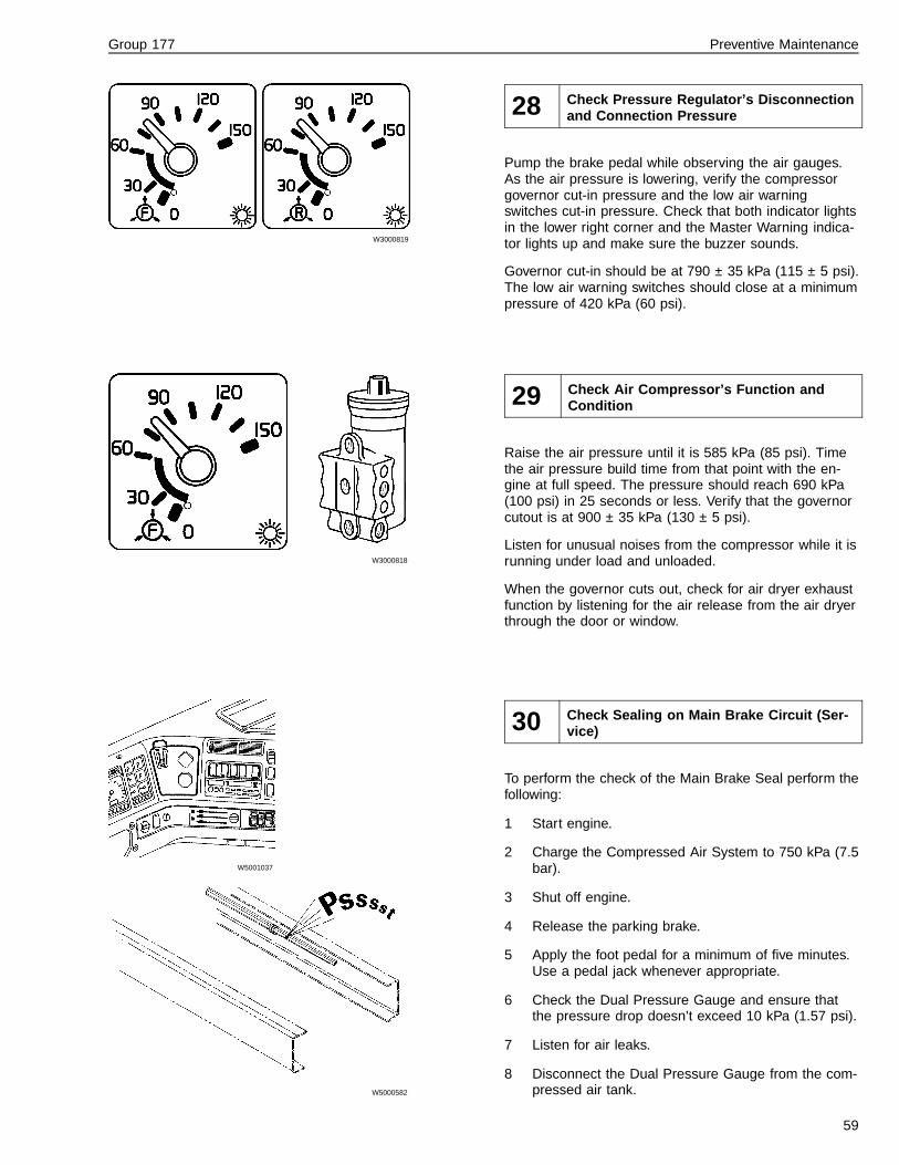
28 Check Pressure Regulator’s Disconnectionand Connection Pressure
Pump the brake pedal while observing the air gauges.As the air pressure is lowering, verify the compressorgovernor cut-in pressure and the low air warningswitches cut-in pressure. Check that both indicator lightsin the lower right corner and the Master Warning indica-tor lights up and make sure the buzzer sounds.
Governor cut-in should be at 790 ± 35 kPa (115 ± 5 psi).The low air warning switches should close at a minimumpressure of 420 kPa (60 psi).
W3000818
29 Check Air Compressor’s Function andCondition
Raise the air pressure until it is 585 kPa (85 psi). Timethe air pressure build time from that point with the en-gine at full speed. The pressure should reach 690 kPa(100 psi) in 25 seconds or less. Verify that the governorcutout is at 900 ± 35 kPa (130 ± 5 psi).
Listen for unusual noises from the compressor while it isrunning under load and unloaded.
When the governor cuts out, check for air dryer exhaustfunction by listening for the air release from the air dryerthrough the door or window.
W5001037
W5000582
30 Check Sealing on Main Brake Circuit (Ser-vice)
To perform the check of the Main Brake Seal perform thefollowing:
1 Start engine.
2 Charge the Compressed Air System to 750 kPa (7.5bar).
3 Shut off engine.
4 Release the parking brake.
5 Apply the foot pedal for a minimum of five minutes.Use a pedal jack whenever appropriate.
6 Check the Dual Pressure Gauge and ensure thatthe pressure drop doesn’t exceed 10 kPa (1.57 psi).
7 Listen for air leaks.
8 Disconnect the Dual Pressure Gauge from the com-pressed air tank.
59

Group 177 Preventive Maintenance
W5000599
31 Check Parking Brake and Blocking Valve
Check the parking brake and blocking valve holdingpower by engaging direct gear, not allowing the enginespeed to go above 1000 rpm and attempt to drive offwith the parking brake still applied. The parking brakeshould hold the vehicle stationary while letting the clutchup slowly.
Release the parking brake and start driving. Check thatthe parking brakes are released quickly and that nobraked drag can be felt.
W4000760
W8001384
32 Check Gear Shift and Clutch Pedal
To perform a service check on the Gear Shift and ClutchPedal, complete the following:
1 Move the gearshift to range and split gear positions.Listen to the sound when passing through neutraland checking the range gear. The control lampshould light up when the high split gear is engaged.
2 Check, on the automatic gearbox, that the enginecan only be started when the gear selector is inneutral (N).
3 Check that there is no excessive play in thegearshift.
4 Check that the gear stick gaiter fits tightly and is notcracked.
60

Group 177 Preventive Maintenance
W3000810
33 Check Bogie Lift
Check the bogie lift by pressing the air suspension level-ling switch. Verify function by watching the chassis beinglowered. Verify that the telltale indicator lights up on theinstrument cluster.
W5000607
34 Check Brake Pedal and Foot Brake Valve
Letting the engine run at low idle, depress the brakepedal to full brake pressure (depress pedal only once sothe compressor does not start loading again). Let thebrake pressure stabilize. Hold pressure steady for oneminute and check that there is no leakage by observingthe air pressure gauges for pressure decrease. Maxi-mum leak permitted over one minute is 10 kPa (1.5 psi).
61

Group 177 Preventive Maintenance
W8000890
35 Check Hinges, Doorstops, Locks and Seal-ing Strips
Check the following door functions and verify their opera-tion:
— Check that the door hangs properly on the hingesand that the lock functions properly.
— Check that doorstops and sealing strips are in work-ing condition, free from damage and improper wear.
62

Group 177 Preventive Maintenance
External Checks
W3004425
36 Function Check of External Lamps
To perform a function check of the external lamps, per-form the following:
1 Check all external lighting for operation.
2 Check that all lamps are in good condition.
W8001420
37 Check Rear View Mirrors and Reflectors
To perform a function check of the mirrors and reflectors,complete the following:
1 Check that the rear view mirrors are in good work-ing condition and remain in position when set.
2 Check the attachments for the rear view mirrors andensure they are functional.
3 Check the reflectors for functionality and that noneare missing.
63

Group 177 Preventive Maintenance
W3000786
38 Function Check of Wipers and Washers
Check the wiper arm tension and condition of the wiperblades.
W3000784
39 Check Headlamps
Check alignment and output of headlights.
64

Group 177 Preventive Maintenance
W8000990
40 Check Air Filter for Ventilation System
For further information concerning component specifica-tions see service information in Group 8 and appropriatevendor literature.
The fresh air filter should be inspected every 64,000 km(40,000 miles) for regular highway use. In very dustyconditions, it is recommended that the filter be checkedevery 16,000 km (10,000 miles). Replace with a new fil-ter every 113,000 km (70,000 miles).
W8000989
Check that the evaporator drain nipple is open bysqueezing the end to let water drain out.
W8000955
If equipped, check the bunk unit air filter — located be-hind the passenger seat on bunk support. The bunk unitair filter should be inspected at regular intervals, approxi-mately every 112,654 km (70,000 miles). The filtershould be changed after 160,934 km (100,000 miles).
65

Group 177 Preventive Maintenance
C8000117
41 Check Refrigerant Reservoir, Condenser,Pipes and Hoses
WARNING
Before working on a vehicle, set the parking brakes,place the transmission in neutral and chock thewheels. Failure to do so can result in unexpectedvehicle movement and can cause serious personal in-jury or death.
1 Ensure that the Refrigerant Reservoir is filled.
2 Using the leak detector, check the following forleaks:
• Compressor thread connections.
• Compressor crimp connections.
• Compressor shaft seal.
• Condensor tube connections.
• Receiver/dryer connections.
• Cab expansion valve.
• Cab evaporator connections.
• Pressure switch connections.
• Schrader valve connections.
• All refrigerant tubing bends and weld joints.
3 Recheck for leaks after performing any repair or re-placement.
66

Group 177 Preventive Maintenance
W8001066
W8001065
42 Check Air Intake and Air Deflector
Check the air intake grille and air bellows for cracks,breaks and broken tabs and clips
W2001069
43 Check Hood Attachement and Locking De-vices
Open the hood and check condition of hood restraintcylinders and splash shields.
Note: The restraint cylinders are oil-filled and work likeshock absorbers.
W8000926
Check hood lock cables for function and condition. Makesure they are not fraying.
Operate the lock to see if it moves without binding.
Inspect cab air suspension condition.
67
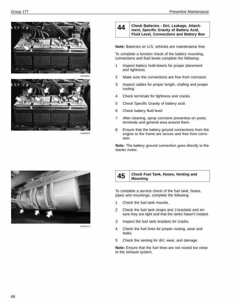
Group 177 Preventive Maintenance
W3000823
W3000859
44 Check Batteries - Dirt, Leakage, Attach-ment, Specific Gravity of Battery Acid,Fluid Level, Connections and Battery Box
Note: Batteries on U.S. vehicles are maintenance free.
To complete a function check of the battery mounting,connections and fluid levels complete the following:
1 Inspect battery hold-downs for proper placementand tightness.
2 Make sure the connections are free from corrosion.
3 Inspect cables for proper length, chafing and properrouting.
4 Check terminals for tightness and cracks.
5 Check Specific Gravity of battery acid.
6 Check battery fluid level.
7 After cleaning, spray corrosive preventive on posts,terminals and general area around them.
8 Ensure that the battery ground connections from theengine to the frame are secure and free from corro-sion.
Note: The battery ground connection goes directly to thestarter motor.
W2001071
45 Check Fuel Tank, Hoses, Venting andMounting
To complete a service check of the fuel tank, hoses,pipes and mountings, complete the following:
1 Check the fuel tank mounts.
2 Check the fuel tank straps and J-brackets and en-sure they are tight and that the tanks haven’t rotated.
3 Inspect the fuel tank brackets for cracks.
4 Check the fuel lines for proper routing, wear andleaks.
5 Check the venting for dirt, wear, and damage.
Note: Ensure that the fuel lines are not routed too closeto the exhaust system.
68

Group 177 Preventive Maintenance
W2001226
46 Check Fuel Tank Ventilation Filter
To complete a service check of the fuel tank ventilationfilter, complete the following:
1 Inspect the tanks for damage, leaks and corrosion.
2 Inspect tank vents.
69

Group 177 Preventive Maintenance
47 Draining of Fuel Tank (Dirt, Water)
To complete a service check of the fuel tank ventilationfilter, complete the following:
• Drain the fuel tank and check for dirt or water in thefuel system.
W2001067
48 Check Fuel Water Seperator for Fuel Sys-tem, Draining of Condensation
For further information concerning component specifica-tions see service information in Group 1, “Oil and FilterChange Intervals for Volvo Components,” publicationnumber 175-001, and appropriate vendor literature.
If the filter is not being changed, drain the water separa-tor.
70

Group 177 Preventive Maintenance
W7000437
49 Check Tire Wear
Tire Wear
1 Examine each tire tread for unusual wear patterns.Refer to chart below for typical tread patterns.
2 Measure tread depth.
3 Check tire pressure and leak-test valve stems.
W1000062
71

Group 177 Preventive Maintenance
Engine Compartment Checks
W3000978
50 Check Alternator Mounting
Check the alternator mounting for wear or damage.
W3000978
51 Check Electrical Connections and Cablesfor Alternator, Starter Motor, and Preheater
• Check the electrical connections for the alternator,starter motor, preheater for dirt, corrosion and dam-age.
72

Group 177 Preventive Maintenance
W2003743
1 — Tensioner against the install stop or free-armstop.
W2003742
2 — Metal-to-metal contact between the arm andspringcase.
52 Check Drive Belts
Ensure that the engine cannot be started while work-ing around the fan area. Failure to do so may result inserious personal injury or death.
For further information refer to Function Group 2 and ap-propriate vendor literature.
To perform a function check of the drive belts completethe following:
1 Using a belt tension meter, check fan belts for cor-rect tension.
Note: For manual tensioning systems only.
2 Inspect the belts for wear, cracks, and fraying.
3 Check along the belts for proper alignment.
4 Visually inspect hubs and pulleys for wear and dam-age.
5 Inspect the vibration damper for leaks or any sur-face damage.
6 With belt on the drive:
• Check if the tensioner is against the install stopor free-arm stop. Replace the belt if this condi-tion is seen.
• Check if the belt is tracking all the way to oneedge of the tensioner pulley. A witness mark,considerably wider than the belt, may be seenon the pulley under this condition and the ten-sioner should be replaced.
7 Remove the belt by pulling the tensioner back with abreaker bar. Slowly return the tensioner to its freearm stop. Perform the following:
• With the breaker bar, slowly pull the tensionerback from the free arm stop to the install stopand slowly release again. If the tensioner ex-hibits excessive ’roughness’ or hesitancy duringthis cycle, replace the tensioner.
• Check for metal-to-metal contact between thearm and springcase. Replace if metal-to-metalcontact is seen.
• Check to see if there are any cracks in the ten-sioner or if the stops on the springcase arebroken. Replace the tensioner if either of theseconditions is seen.
8 Reinstall the belt ensuring that the belt is properlyseated in the grooves of all pulleys.
73
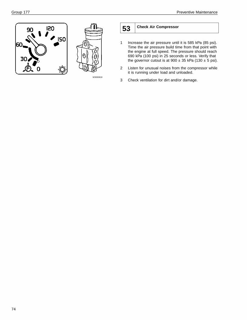
Group 177 Preventive Maintenance
W3000818
53 Check Air Compressor
1 Increase the air pressure until it is 585 kPa (85 psi).Time the air pressure build time from that point withthe engine at full speed. The pressure should reach690 kPa (100 psi) in 25 seconds or less. Verify thatthe governor cutout is at 900 ± 35 kPa (130 ± 5 psi).
2 Listen for unusual noises from the compressor whileit is running under load and unloaded.
3 Check ventilation for dirt and/or damage.
74

Group 177 Preventive Maintenance
W2001414
54 Check Engine Mounting
To perform a check of the engine mounting complete thefollowing:
• Check all brackets, bolts and other engine mountingparts for dirt, wear, and damage.
W2002080
55 Check Radiator Mounting
To perform a check of the radiator mounting, completethe following:
• Check all brackets, bolts, and other radiator mount-ing parts for dirt, wear, and damage.
75

Group 177 Preventive Maintenance
W2001075
56 Check Radiator Fan, Bearing Tolerance,Bolt Unions, Fan Shroud and Fan Ringwith Rubber Seal
Ensure that the engine cannot be started while work-ing around the fan area. Failure to do so may result inserious personal injury or death.
Perform the check of the radiator fan as follows:
1 Inspect fan blades for any damage.
2 Ensure there is enough clearance between the fanblade tips and the fan ring in the shroud.
Note: The minimum clearance is 3 mm (0.12 in.) atany point around the fan ring.
3 Loosen the belts and rotate the fan hub assembly.Check for roughness and binding in the bearings.Check that the end play does not exceed 1.5 mm(1/16 in.).
4 Check fan clutch for lining wear or air leaks. Lubri-cate fan hub, if applicable.
5 Inspect the idler pulley for cracks.
6 Check for bearing roughness and binding.
7 Inspect the belt driven water for bearing wobble andany evidence of leakage.
8 Check the radiator package mounts, bearing toler-ance and bolt unions.
9 Inspect rubber cushions for wear.
10 Inspect fan shroud rubber molding and all fastenersfor wear and tightness.
W2001430
57 Pressure Testing of Cooling System
To complete a pressure test of the cooling system:
• Pressure test the cooling system using tool J-44399.
76

Group 177 Preventive Maintenance
W2001496
58 Check Radiator, Hoses, Pipes and Air Flow
WARNING
Do not remove the cap from the coolant surge tankwhile the engine and radiator are still hot. Scaldingfluid and steam may be blown out by pressure if thecap is removed while the engine and radiator are hot.
Note: This check is also considered Noise EmissionsControl Maintenance, which is required maintenance forany Volvo vehicle. For further information on Noise Emis-sions refer to “Noise Emissions” page 5.
Perform the check of the radiator, hoses and pipes asfollows:
1 Check the front area of the radiator package for dirtand debris that hinders air flow.
2 Clean the radiator package with compressed air orwater pressure, blowing or pushing from the insideout.
Note: Air pressure should not exceed 200 kPa (30psi) for the radiator and charge air cooler cores.
Note: If there is damage to the cooling fins,straighten them out so air can flow freely.
3 Check for fluid leaks on or around the engine.
Note: Inspect the mating surfaces, auxiliary compo-nent attaching areas and hook-ups, hoses andpipes.
4 Pump up pressure in the relief valve, with the heatercontrols open, to 75 kPa (11 psi). Leave under pres-sure for five to ten minutes. Look for leaks, wear,cracking and distortion on hoses and tubing.
5 Check the hose clamps for tightness.
77

Group 177 Preventive Maintenance
T2015533
59 Check Intercooler Pipes, Hoses and AirFlow
Note: This check is also considered Noise EmissionsControl Maintenance, which is required maintenance forany Volvo vehicle. For further information on Noise Emis-sions refer to “Noise Emissions” page 5.
WARNING
Always wear appropriate eye protection to prevent therisk of eye injury due to contact with debris or fluids.
To perform a check of the intercooler pipes and hoses,complete the following:
• Inspect the charge-air-cooler for cracks.
Note: Do not operate the vehicle with a damaged or bro-ken charge-air-cooler. This voids the warranty and theengine will not meet emission regulation requirements.
The best method to clean the package is to use air pres-sure or water stream. Clean from the back of the core.Air pressure should not exceed 30 psi (200 kPa) for radi-ator and charge-air-cooler cores. The use of fin comb isalso a good tool to loosen bugs and dirt from the fins.
Note: If the dirt cannot be cleaned off, consult yourVolvo Truck dealer.
W4002380
60 Check Tightness of Engine and PTO
For further information refer to Group 4.
To complete a check of the tightness of the engine andPTO, complete the following:
1 Check that the engine does not leak oil or coolant.
2 Check that the fittings, flanges and hose connec-tions are tight.
3 Check that hoses or pipes do not chaff or arecracked.
4 Check that the PTO or lines do not leak oil.
78
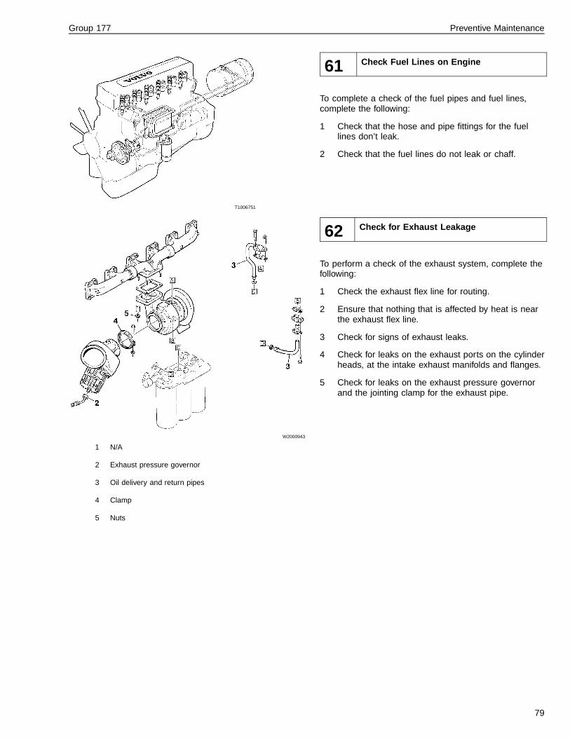
Group 177 Preventive Maintenance
T1006751
61 Check Fuel Lines on Engine
To complete a check of the fuel pipes and fuel lines,complete the following:
1 Check that the hose and pipe fittings for the fuellines don’t leak.
2 Check that the fuel lines do not leak or chaff.
W2000943
1 N/A
2 Exhaust pressure governor
3 Oil delivery and return pipes
4 Clamp
5 Nuts
62 Check for Exhaust Leakage
To perform a check of the exhaust system, complete thefollowing:
1 Check the exhaust flex line for routing.
2 Ensure that nothing that is affected by heat is nearthe exhaust flex line.
3 Check for signs of exhaust leaks.
4 Check for leaks on the exhaust ports on the cylinderheads, at the intake exhaust manifolds and flanges.
5 Check for leaks on the exhaust pressure governorand the jointing clamp for the exhaust pipe.
79
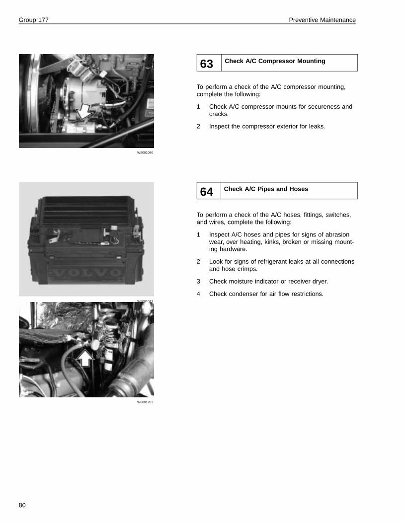
Group 177 Preventive Maintenance
W8001090
63 Check A/C Compressor Mounting
To perform a check of the A/C compressor mounting,complete the following:
1 Check A/C compressor mounts for secureness andcracks.
2 Inspect the compressor exterior for leaks.
W8001017
W8001283
64 Check A/C Pipes and Hoses
To perform a check of the A/C hoses, fittings, switches,and wires, complete the following:
1 Inspect A/C hoses and pipes for signs of abrasionwear, over heating, kinks, broken or missing mount-ing hardware.
2 Look for signs of refrigerant leaks at all connectionsand hose crimps.
3 Check moisture indicator or receiver dryer.
4 Check condenser for air flow restrictions.
80

Group 177 Preventive Maintenance
T2006949
65 Check Air Pipe between Air Intake andTurbo
To perform a check of the air pipe between the air intakeand turbo, complete the following:
• Check the air pipe etween the air intake and turbofor wear, damage, and cracks.
T2012805
T2012806
66 Check Turbocharger and Regulator
Before working on a vehicle, set the parking brakes,place the transmission in neutral, and block thewheels. Failure to do so can result in unexpectedvehicle movement and can cause serious personal in-jury or death.
WARNING
HOT ENGINE! Keep yourself and your test equipmentclear of all moving parts or hot engine parts and/orfluids. A hot engine and/or fluids can cause burns orcan permanently damage test equipment.
To complete a check of the turbocharger and regulator,complete the following:
1 Check the turbocharger, attached oil pipes, clamps,nuts, and airlines for wear, damage, dirt, and cracks.
2 Check the regulator for wear, damage, dirt andcracks.
81

Group 177 Preventive Maintenance
67 Check Pump Coupling for Injection Pump(Electronic Engines Not Applicable)
To perform a check of the pump coupling for the injectionpump, complete the following:
• Check the pump coupling is in good condition andclean. There must be no traces of oil or other impu-rities.
W6001428
68 Check Tightness on Servo Pump, Oil Linesand Steering Gear
To perform a check of the tightness on the servo pump,oil lines, and steering gear, complete the following:
• Check that the servo pump is secured tightly to thetransmission. Also check for excessive dirt, wear ordamage.
• Check that the oil lines are secure and free from ex-cessive dirt, wear or damage.
• Ensure that the steering gear is secure and freefrom excessive play.
• Check that the power steering pump is securely fas-tened to the engine.
• Ensure that the power steering hoses are securedand free of leaks.
69 Check Sound Baffles for Engine
This option not applicable to the VN/VHD vehicles.
82

Group 177 Preventive Maintenance
Front Suspension, Steering System Checks
W6000869
70 Check Steering Linkage
To perform a check of the servo pump and steering gear,complete the following:
1 Check the steering shaft, drag link, and tie-rod. In-spect for damage or external wear.
2 Check joints for play by manually pushing andpulling each ball stud.
W7001242
1 Upper Shock Mount Bracket2 Eyelet3 Mounting Bolt4 Chassis5 Shock Absorber6 Front Spring7 Front Axle Beam8 Lower Shock Mount Bracket9 Bushing
71 Check Front Shock Absorbers
To perform a check of the front shock absorbers, com-plete the following:
1 Check the rubber mounting bushings for wear ordamage.
2 Disconnect the lower end and work the shock ab-sorber by hand to see that the outer tube is notstriking or rubbing against the fluid reservoir tube.
3 While the shock absorber is disconnected, checkthe piston movement by pulling and pushing the ab-sorber down and up slowly to insure the piston doesnot bind in the pressure tube.
Note: There should be considerable resistancewhen extending the absorber, but only slight resis-tance when collapsing the unit.
83

Group 177 Preventive Maintenance
W6000869
72 Check Steering Knuckle Bearing
To perform a check of the steering knuckle bearing,complete the following:
• Check the steering knuckle bearing for excessivedirt, wear, or damage.
W7000447
W7000448
73 Check Front Wheel Bearings
To perform a check of the front wheel bearing clearance,complete the following:
• Check wheel bearings with a dial indicator. Bearingclearance should be within 0.04 to 0.12 mm (0.001to 0.005 in.).
84

Group 177 Preventive Maintenance
W7001075
Fig. 3: Disc Wheel Hub
1 Disc Wheel
2 Hub
W7001076
Fig. 4: Rim and Spoke Wheel
1 Rim
2 Spoke Wheel
74 Check Front Wheels
To perform a check of the front wheels, complete the fol-lowing:
1 Inspect the hub and tires for excessive dirt, wear ordamage.
2 Check the tire pressure to ensure proper tire infla-tion. Refer to the appropriate vendor literature forinformation concerning tire inflation.
85
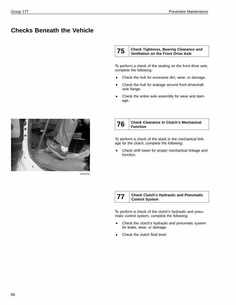
Group 177 Preventive Maintenance
Checks Beneath the Vehicle
75 Check Tightness, Bearing Clearance andVentilation on the Front Drive Axle
To perform a check of the sealing on the front drive axle,complete the following:
• Check the hub for excessive dirt, wear, or damage.
• Check the hub for leakage around front driveshaftaxle flange.
• Check the entire axle assembly for wear and dam-age.
W4000760
76 Check Clearance in Clutch’s MechanicalFunction
To perform a check of the slack in the mechanical link-age for the clutch, complete the following:
• Check shift tower for proper mechanical linkage andfunction.
77 Check Clutch’s Hydraulic and PneumaticControl System
To perform a check of the clutch’s hydraulic and pneu-matic control system, complete the following:
• Check the clutch’s hydraulic and pneumatic systemfor leaks, wear, or damage.
• Check the clutch fluid level.
86

Group 177 Preventive Maintenance
W4000760
78 Check Clutch Wear
Start the test drive by checking clutch pedal play andclutch operation. Clutch pedal play should be 4 to 10mm (0.15 to 0.40 in.), which is the clearance betweenthe pedal plunger and the piston in the master cylinder.
On vehicles with clutch brake, check function by de-pressing clutch pedal to within 6 to 12 mm (1/2 to 1 in.)from the floor while engaging a gear. There should be nograting of the engagement teeth when the clutch brake isengaged.
W4000770
79 Check Transmission’s Pneumatic and Me-chanical Control System
To perform a check of the transmission’s pneumatic andmechanical control system, complete the following:
1 Check the top of the transmission.
2 Inspect lower shift boot condition.
3 Inspect the top covers for leakage and the shift leverfor leakage and wear.
T1006766
80 Check Seals for Speedometer Sensor andJoint Coupling
To perform a check of the seals for the speedometersensor and joint coupling, complete the following:
1 Check the speedometer sensor seals for wear,cracks, or any other damage.
2 Check the joint coupling for secureness and wear ordamage.
87

Group 177 Preventive Maintenance
W4002380
81 Check Tightness on Transmission, Trans-fer Case, and Power Take-off includingcheck of lines
To perform a check of the tightness of the transmission,transfer case, and power take off complete following:
• Visually check the transmission for secureness andany worn or broken clamps, bolts, or other securingdevices.
• Visually check the transfer case for secureness andany worn or broken clamps, bolts, or other securingdevices.
• Visually check the PTO for secureness and any wornor broken clamps, bolts or other securing devices.
• Check all lines and hoses for leaks.
W4000769
Oil Cooler
W4002536
Oil/Water Cooler
82 Check Tightness on Cooler for Transmis-sion
To perform a check of the tightness of the oil cooler forthe transmission, complete following:
• On the oil cooler, check the coolant lines for properrouting and that there are no leaks.
If the oil cooler is air-cooled, complete the following:
1 Check transmission cooler for oil leaks.
2 Check that the air flow is free through the core.
3 Check all the transmission’s pneumatic pipes andhoses for cracks and leaks.
88

Group 177 Preventive Maintenance
W4002380
83 Check Ventilation for Transmission,Transfer Case, and Power Take-Off
To complete a check of the ventilation for the transmis-sion, transfer case and power take off, complete thefollowing:
• Check that the air flow is free through the core forthe transmission, transfer case and power take off.
84 Check Tightness on Retarder and checklines
Not applicable for the VN/VHD vehicles.
85 Check Sound Baffle for Gearbox
Not applicable to VN/VHD vehicles.
89

Group 177 Preventive Maintenance
W1000035
86 Check Transfer Case’s Mounting
Not applicable for the VN/VHD vehicles.
87 Check Drive Belt for Power Steering
Not Applicable for the VN/VHD vehicles.
90

Group 177 Preventive Maintenance
W4000762
W4000751
88 Check Drive Shaft, Universal Joints, Slid-ing Joints and Support Bearings
To perform a check of the driveshaft, universal joints, slid-ing joints and support bearings complete the following:
1 Check transmission output shaft bearing for wear.Move the flange up and down; bearing play shouldnot be greater than 1.5 mm (1/16 in.).
2 Check for oil leaks past the transmission outputshaft seal.
Note: There is a difference between sweating and aleak. If oil is seeping past the seal after cleaning,there is a leak.
3 Check driveshaft U-joints and slip joint for play.There should exist no noticeable play in the U-jointbearings. The slip joint radial play maximum is 0.18mm (0.007 in.).
4 The driveshaft tube should be straight and have nodamage or missing weights. Remove any build-up offoreign material such as undercoating, concrete, etc.
5 Check the torque of driveshaft bolts - they should be170 Nm (125 ± 10 ft-lb).
6 Check center bearing mounting.
7 Check rear axle pinion bearing for wear and leakspast the seal.
Note: The Volvo CT EV87 front tandem gear input shafthas a large play for the input shaft bearing. This is nor-mal and does not have any damaging effect on thetransfer gear-during rotation, the shaft is balanced sothat the clearance is insignificant. If there is no oil leak-age there is no reason for concern about this play.
W4000754
89 Check Tightness of Rear Axle and HubReduction Gear
To perform a check of the sealing on the rear axle andhub reduction gear, complete the following:
1 On the rear axle, inspect around the mating sur-faces for leaks past the gasket.
2 Check brake chamber and air tubing condition.
3 Check hub reduction gear for any leaks or crackedsealant.
91

Group 177 Preventive Maintenance
W4000752
90 Check Bearing Clearance in Pinion andRear Axle Input Shaft
To perform a check of the bearing clearance in the pin-ion and rear axle, complete the following:
1 Use a dial indicator to check bearing clearance inthe pinion and rear axles. The clearance should bewithin 0.04 to 0.12 mm (0.001 to 0.005 in.).
W4000754
91 Check Rear Drive Axle Ventilation
To perform a check of the rear drive axle ventilation,complete the following:
• Check the rear drive axle for proper ventilation; itshould also be free from excessive dirt, wear, ordamage.
92

Group 177 Preventive Maintenance
92 Check Exhaust Pipe and Silencer
Note: This check is also considered Noise EmissionsControl Maintenance, which is required maintenance forany Volvo vehicle. For further information on Noise Emis-sions refer to “Noise Emissions” page 5.
To perform a check of the exhaust pipe, silencer or par-ticulater, complete the following
• Check if there is exhaust leakage around the ex-haust ports on the cylinder heads, at the intake andexhaust manifolds, and at the flanges; exhaustpipe(s) and silencer.
• Check if there is exhaust leakage at the jointingclamp for the front exhaust pipe.
W6000827
93 Check Rear Springs and U-Bolts
To perform a check of the springs and U-bolts, completethe following:
1 Check the springs for damaged or broken leaves.
2 Check the spring bushing location in the spring eye.
3 Inspect the U-bolts for signs of movement or wear.
4 Check that the spring center is aligned with the cen-ter of the spring pad on the front axle beam. Verifythis alignment by inspecting the underside of thespring to see if there are any signs of movement be-tween the spring and the axle member.
94 Check Anti-Roll Bar
Not applicable to VN/VHD vehicles.
93

Group 177 Preventive Maintenance
W6000836
95 Check Rear Shock Absorbers
For further information refer to 761-002, “Shock Ab-sorbers, Front and Rear.”
To perform a check of the rear shock absorbers, com-plete the following:
• Check the rear shock absorbers for excessive dirt,wear, or damage.
W7000763
96 Check Mounting for Front and Rear Axle
To perform a check of the mounting for the front and rearaxles, complete the following:
1 Check the mounting for the front axle for tightnessand excessive wear and damage.
2 Check the mounting for the rear axle for tightnessand excessive wear and damage.
94

Group 177 Preventive Maintenance
W5001185
97 Check Bogie Lift or Lift Axle
To perform a check of the bogie lift or lift axle, completethe following:
1 Check the lift axle for excessive wear and damage.
2 Check the lift axle air lines for leaks or cracks.
3 Check the lift axle springs for wear or damage.
4 Check the lift axle for proper operation.
95

Group 177 Preventive Maintenance
W7000444
Air Bellow
W7000759
Leveling Valve
98 Check Rear Suspension Level Sensorsand Leveling Valves
To perform a check of the air bellow, level sensors andlevel valves for the air suspension, complete the follow-ing:
1 Check the air spring for wear and cracks.
2 Check the level valve for proper operation.
3 Check the leveling valve for wear and damage.
4 Check rod control linkage.
99 Check Height Regulation for Air Suspen-sion
Not applicable for VN/VHD vehicles.
W0001880
100 Check Chassis Frame and Crossmembers
To perform a check of the chassis frame and crossmem-bers, complete the following:
1 Check the chassis frame for excessive wear or dam-age.
2 Check the securing fastners for looseness, exces-sive wear or damage.
3 Check the crossmembers for excessive wear ordamage.
96

Group 177 Preventive Maintenance
101 Check Central Lubrication System
Not applicable for VN/VHD vehicles.
W5000764
102 Check Compressed Air Lines and Hoses
For further information refer to 560-660, “CompressedAir Brakes, All Models.”
To perform a check of the compressed air lines andhoses, complete the following:
• Check the compressed air lines and hoses for leaksand cracks.
• Check the securing fasteners for tightness and wearor damage
97

Group 177 Preventive Maintenance
103 Check Rear Wheel Bearings
Note: For further information, refer to Service Informa-tion, Group 7 and “Hubs” page 26.
Failure to keep wheel bearings properly adjusted canresult in accelerated tire wear, poor handling and, inextreme cases, wheel separation from the hub or fromthe spindle resulting in loss of vehicle control and se-rious personal injury or death.
Note: Avoid mixing Synthetic and petroleum lubricants inthe same component.
The wheel hubs are lubricated with several types of oil. Itis acceptable to use either synthetic or petroleum basedoils (synthetic oils are not recommended for Volvo Axles).
Hubs are generally oil-lubricated. There are no set oilchange intervals. Change oil when the hub is removedfor repairs or other routine maintenance.
98

Group 177 Preventive Maintenance
W7000437
104 Check Rear Wheels
Tire Wear
For further information, refer to Service Information,Group 7.
1 Examine each tire tread for unusual wear patterns.Refer to chart below for typical tread patterns.
2 Measure tread depth.
3 Check tire pressure and leak-test valve stems.
4 Check the Rim Flange wear on Aluminum Wheelsevery time the wheel is replaced.
Note: The main causes of tire wear are faulty air pres-sure, incorrect toe adjustment, and incorrect drive tirealignment or thrust angles, which can cause pushing orscrubbing of the steer tires. Feathered edges of the tiresis an early symptom of tire wear.
T1006487
105 Check Differential Locks
To perform a check of the differential locks, complete thefollowing:
1 Check the differential locks for wear or damage.
2 Check that the differential locks are operational.
99

Group 177 Preventive Maintenance
W5000610
W5000604
106 Check Brake Linings
To perform a check of the brake linings, complete the fol-lowing:
• Measure the brake lining through the inspectionholes in the backing plates. See manufacturer’sspecifications for minimum lining thickness.
107 Check Brake Cylinders, Levers, and Forks
To perform a check of the brake cylinders, levers andforks, complete the following:
1 Remove the wheel and brake drums.
2 Inspect the brake cylinders, levers and forks forsigns of wear, warp or cracks.
W5001317
108 Check Brake Disc and Calipers
Note: Not applicable for VN vehicles.
To perform a check of the brake discs and calipers, com-plete the following:
1 Remove the wheel.
2 Inspect the brake discs and calipers for signs ofwear or damage.
100

Group 177 Preventive Maintenance
W5000613
109 Check Stroke Length on Slack Adjusters,Brake Levers, and Brake Drum Travel
To perform a check of the brake lever, slack adjuster,and brake drum travel, complete the following:
1 Remove the wheel and brake drums.
2 Inspect brake lever for signs of wear or damage.
3 Check the connecting clevis, pins, slack adjustersand brake chambers for wear or damage.
4 Verify the following specifications for slack adjusterstroke:
Relax Stroke Use steel tape to measure from thechamber face to the center pushrod eye.
Note: 70 mm (2.75 in.) minimum,73 mm (2.88 in.) maximum.
Free Stroke Use a pry bar and steel tape tomeasure from the chamber face tothe center push rod eye.
Note: A - B = 9mm (.37 in.)
AppliedStroke
Max. pressure for the appliedstroke is 586 kPa (85 psi)
Note: Type 16/20 chambers, A - C= 44 mm (1.75 in.). Type 30/30chambers, A - C = 51 mm (2 in.).
5 Check the drum diameters using an inside microme-ter. The maximum drum diameter is stamped on thedrum edge. Also refer to any available vendor litera-ture for further information.
6 Verify that the length of both slack adjusters on anaxle is the same.
7 Inspect the brake drums for oil, cracks, heat spots,or heavy wear.
101

Group 177 Preventive Maintenance
110 Check Load Sensing Valve
Not applicable for VN/VHD vehicles.
111 Check Brake Chambers and MountingBrackets
To perform a check of the brake chambers and mountingbrackets, complete the following:
1 Inspect the brake chambers and mounting bracketsfor wear and damage.
2 To ensure correct brake balance, all the brakechambers for each axle must be of the same sizeand type. This balance will ensure maximum brakelining performance.
102

Group 177 Preventive Maintenance
Test Driving
W4000760
W5000599
112 Check After Start
Check Clutch Operation
Start the test drive by checking clutch pedal play andclutch operation. Clutch pedal play should be 4 to 10mm (0.15 to 0.40 in.), which is the clearance betweenthe pedal plunger and the piston in the master cylinder.
On vehicles with clutch brake, check function by de-pressing clutch pedal to within 6 to 12 mm (1/4 to 1/2in.) from the floor while engaging a gear. There shouldbe no grating of the engagement teeth when the clutchbrake is engaged.
Check Parking Brake and Clutch Slip
Check for parking brake holding power and also forclutch slippage by engaging direct gear, not allowing theengine speed to go above 1,000 rpm and attempt todrive off with the parking brake still applied. The parkingbrake should hold the vehicle stationary while letting theclutch up slowly.
If the clutch slips or the truck moves forward during thisoperation, note on form for later inspection of either theclutch or spring brake operation.
Release parking brake and start driving. Check that theparking brakes are released quickly and that no brakedrag can be felt.
103
Group 177 Preventive Maintenance
W5000617
113 Check During Test Driving
Check Clutch Operation
During driving, check for smooth operation and engage-ment when shifting gears. Look for uneven engagementand/or unusual noise.
Wheel Brake Application and Release
To do the brake test safely, make sure there are noother vehicles within 300 yards when testing, or per-form the test in a off-road area where there is notraffic. Performing brake test in traffic may lead to anaccident, personal injury or death.
During the first part of driving, check the wheel brakes.Check for even application and release. Make sure thevehicle does not pull to the side when the brakes are ap-plied and that the noise is not generated while braking.
Whether or not a truck is equipped with ABS brakes, thebobtail proportioning valve will operate as designed, reg-ulating air brake pressure going to the rear wheel brakeswhile not hooked up to a semitrailer. Rear wheels shouldnot lock up during moderate braking when in bobtailmode.
Note: The rear wheels may lock intermittently while driv-ing unloaded under 30 km/h (20 mph) even whenequipped with ABS brakes. This is normal in unloadedoperation.
104

Group 177 Preventive Maintenance
W5000614
Check ABS System
To do the brake test safely, make sure there are noother vehicles within 300 yards when testing, or per-form the test in a off-road area where there is notraffic. Performing brake test in traffic may lead to anaccident, personal injury or death.
Check the ABS system by attempting to lock up thewheels during hard braking. The vehicle should come toa controlled stop. Brake from a speed of 50 to 55 km/h(30 to 35 mph). Make a full brake application.
Note: The rear wheels may lock intermittently while driv-ing unloaded under 30 km/h (20 mph) even whenequipped with ABS brakes. This is normal in unloadedoperation.
Also check that the ABS telltale indicator comes on andgoes out at approximately 8 km/h (5 mph).
105

Group 177 Preventive Maintenance
W3000815
Check Engine Controls and Performance
Check engine controls and performance while movingthrough the gears. Accelerator pedal should worksmoothly and without any hesitation in engine response.Engine should accelerate smoothly and without hesita-tion, misses or surges. Also check the exhaust throughthe mirrors for excessive smoke during acceleration.
During acceleration in a low gear, let engine go to fullspeed on a flat stretch of road. Note maximum enginespeed. Check the engine manufacturer’s specificationsfor correct speed.
W2001083
W2001084
Check Engine Brakes
When operating a tractor bobtail without a trailer or onslippery roads, the engine brake switch must be in the“OFF” position. Failure to follow these instructions canresult in loss of vehicle control and serious personalinjury or death.
If the engine is equipped with an exhaust brake (Volvoonly) or an engine brake, VEB, check the effectivenessof the retarding force when the brake is engaged.
Engine Brake, VEB
The engine brake has two operation modes, high andlow, that are selected by one or two switches on thedashboard. Make sure the brake function disengages by:
• Either depressing accelerator or clutch pedal.
• Engine speed goes under 1,000 rpm.
• Vehicle speed goes under 2 mph (3 km/h).
• Turbo boost pressure going over 150 kPa (22 psi).
• Engaging PTO.
• Engaging ABS.
106
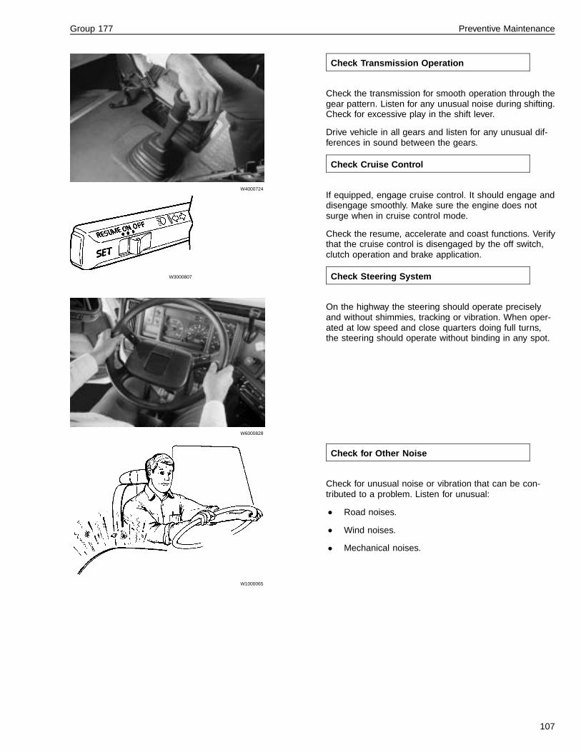
Group 177 Preventive Maintenance
W4000724
W3000807
W6000828
Check Transmission Operation
Check the transmission for smooth operation through thegear pattern. Listen for any unusual noise during shifting.Check for excessive play in the shift lever.
Drive vehicle in all gears and listen for any unusual dif-ferences in sound between the gears.
Check Cruise Control
If equipped, engage cruise control. It should engage anddisengage smoothly. Make sure the engine does notsurge when in cruise control mode.
Check the resume, accelerate and coast functions. Verifythat the cruise control is disengaged by the off switch,clutch operation and brake application.
Check Steering System
On the highway the steering should operate preciselyand without shimmies, tracking or vibration. When oper-ated at low speed and close quarters doing full turns,the steering should operate without binding in any spot.
W1000065
Check for Other Noise
Check for unusual noise or vibration that can be con-tributed to a problem. Listen for unusual:
• Road noises.
• Wind noises.
• Mechanical noises.
107

Group 177 Preventive Maintenance
W3000787
W8000889
Check Instruments and Gauges
Check all instruments and gauges for proper function.
If possible, check the odometer against a measured mile.
Check Heater and Air Conditioning
Check function of heater and air conditioning. Operatethe controls and let the fan run on all speeds.
Note: In the summertime, the shut-off valves for theheater may be closed for the season. Open valves be-fore testing heater.
108

Group 177 Preventive Maintenance
W3000810
114 Check After Test Driving
Check Pneumatic Switches
If vehicle is equipped with a pneumatic 5th wheel slidingrelease, operate release mechanism while listeningthrough door or have a helper check the function. Verifythat the telltale indicator on the instrument cluster lightsup.
Note: If vehicle air pressure is below approximately 720kPa (75 psi), pneumatic switches will not function. This isa safety lockout for the air brake system.
Operate the differential lock switch(es). Verify engage-ment by listening to the lock mechanism operating andthat the telltale indicator lights up on the instrument clus-ter.
If equipped with air suspension levelling switch, operatethe switch. Verify function by watching the chassis beinglowered. Verify that the telltale indicator lights up on theinstrument cluster.
Make sure the lock function of each switch works so thatthe switch can not be engaged without operating the lock.
W6000829
Check Steering Column Adjustment
Press down the release pedal and move the steeringwheel column through its possible positions. It should bepossible to move the steering column without binding orusing excessive force. When the pedal is released, thecolumn should be firmly locked in place.
W8000947
Check Horns
Sound both the air horn (1) and the electrical horn (2).Each should have a strong, even tone.
109

Group 177 Preventive Maintenance
W3000815
Engine Low Idle
Record the engine low idle speed. Listen for idling prob-lems such as surging, missing or unusual noise. Seeeach engine manufacturer’s specification for correct idlespeed.
Record low and high oil pressure.
W3000819
Check Low Air Warning Switches
Pump the brake pedal while observing the air gauges.As the air pressure is lowering, verify the compressorgovernor cut-in pressure and the low air warningswitches cut-in pressure. Check that both indicator lightsin the lower right corner and the Master Warning indica-tor lights up and make sure the buzzer sounds.
Governor cut-in should be at 790 ± 35 kPa (115 ± 5 psi).The low air warning switches should close at a minimumpressure of 420 kPa (60 psi).
W5000612
Check Manifold Dash Valve
Start the manifold dash valve check by pulling out theyellow knob (Parking). At the same time the red knob(Trailer Air Supply) should also pop out. Press bothknobs in.
Note: The gauges should only be used for general refer-ence. Gauges are less accurate below 275 kPa (40 psi).
Lower the air pressure by pumping the foot brake valveto the point where the red knob pops out. Verify that thishappens at a pressure of 275 ± 35 kPa (40 ± 5 psi).
Hold the red knob in manually and decrease the pres-sure further. At a pressure of 210 ± 35 kPa (30 ± 5 psi),a tripper valve starts to exhaust the air supply to thetrailer. This is the non-override function working. Releasethe red knob.
Continue to decrease air pressure until the yellow knobpops out. This should happen at a pressure of 170 ± 35kPa (25 ± 5 psi). Now try to push in both knobs. Theyshould not stay in on their own.
110

Group 177 Preventive Maintenance
W3000818
Check Compressor Loading
Raise the air pressure until it is 585 kPa (85 psi). Timethe air pressure build time from that point with the en-gine at full speed. The pressure should reach 690 kPa(100 psi) in 25 seconds or less. Verify that the governorcutin is at 758 ± 68 kPa (110 ± 10 psi) and cutout is at900 ± 35 kPa (130 ± 5 psi).
Listen for unusual noises from the compressor while it isrunning under load and unloaded.
When the governor cuts out, check for air dryer exhaustfunction by listening for the air release from the air dryerthrough the door or window.
W3000755
Check Wipers and Washer
Check the windshield wipers and washer from inside thecab. Wipers should operate smoothly and without anybinding in the sweep. Listen for any unusual noise. Theblades should clear the swept area without leavingstreaks or missing any spots.
Check the intermittent mode function.
Note: To shorten the interval time, move the lever to nor-mal wipe position, and then to the interval wipe positionagain when the next wiper sweep is desired. This way,the interval can be programmed between 1 – 10 sec-onds.
Operate the windshield washer and check that the spraypattern covers the wind shield effectively.
111

Group 177 Preventive Maintenance
W1000064
115 Finish
Drive Vehicle; Check Fluids
Drive the vehicle around the block to settle the oil and toverify any points that were found during the inspection.
W6000854
Check all fluid levels. Make sure there are no signs ofleakage after changing oils or filters.
W1000061
Clean
Clean all areas that have been dirtied during the testdrive. As a courtesy to the customer, be especially care-ful about making sure the cab area is as clean orcleaner than when the vehicle came into the shop.
Attach a new maintenance sticker.
112

Group 177
Additional Time Based Maintenance
Every:Year
Volvo EngineCheck the engine valve clearance after the first sixmonths of operation. Check every 12 months or 193,121km (120,000 miles) thereafter. Adjust if necessary.
Every:Two Years
Engine CoolantEngine coolant needs to be changed every two yearsunless the maximum mileage has been reached beforethat. See specification section for engine manufacturer’smileage recommendation.
Texaco Extended Life Coolant
Note: For further information on long life coolant refer toService Bulletin 260-002, “Texaco Extended LifeCoolant.”
CAUTION
Long life coolant is colored red for identification pur-poses, so as not to mistake it for conventional, greencoolant. Long life coolant will test as out of additives(SCA), but SCA should not be added.
Fleetgaurd ES Complete Long Life Coolant
Note: For further information on Fleetgaurd ES Com-plete Long Life Coolant refer to the appropriate vendorliterature.
Caterpillar: Coolant Extender AddedIf using long-life coolant in a Caterpillar engine, addcoolant extender every second year.
Fan HubsCheck clutch lining condition and thickness every80,000 km (50,000 miles). Use lining wear gaugeswhere applicable.
Inspect engagement mechanism for air leaks.
Clutch Hydraulic FluidChange the hydraulic fluid in the hydraulic system for theclutch. The clutch hydraulic system fluid collects moisturefrom the air and will eventually hold enough moisture toaffect the metal surfaces in the system unless removed.
Drain fluid by removing the lid for the fluid container andthen drain through the bleed fitting on the clutch slavecylinder into a container.
Use bleeder tool 9996928 to refill the hydraulic systemwith new fluid. Use fluid to specification DOT 4.
113

Group 177
Every:Two to Three Years
Air DryersThe exchange interval of the air dryer cartridge is heavilydependent on how often the compressor cycles off andon and if the climate is hot and moist or cool and dry.
Do not use a dryer cartridge for more than three years. Itmay have to be changed before that. If a large amountof fluid is collecting in the wet tank, then the desiccant inthe dryer may be saturated and needs to be changed.
Every:Three Years
Caterpillar: Engine Valves and In-jector PreloadEngine valve lash adjustment is checked and, if neces-sary, adjusted every third year. At the same time, adjustthe injector preload. Refer to the Caterpillar ServiceManual for correct procedure.
Caterpillar: Engine CompressionBrake Slave Piston LashIf the engine is equipped with an engine compressionbrake, adjust the slave piston lash after the enginevalves are adjusted. Make the adjustment with the en-gine stopped. Refer to the Caterpillar Service Manual foradjustment information.
Every:Four Years
Caterpillar: Long-Life CoolantChangeAt every fourth year or 6000 hours of operation, changecoolant if long-life coolant is used.
Use only clean water to flush out cooling system. Re-place the coolant filter at the same time.
114
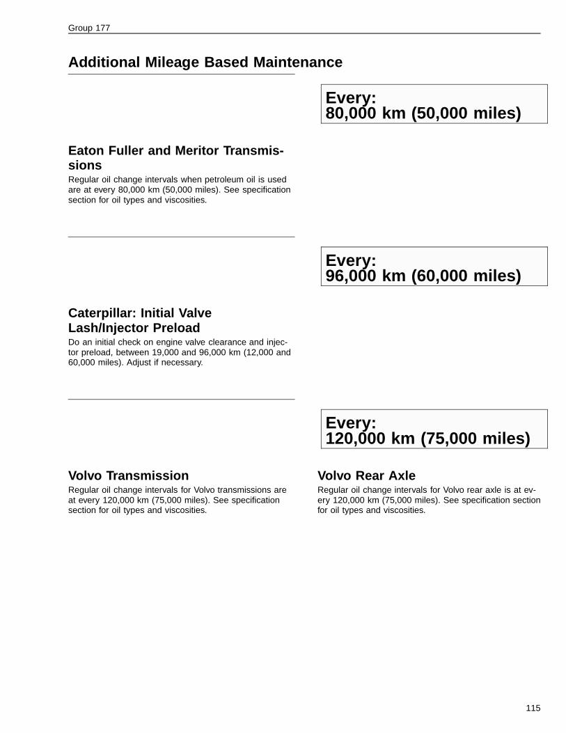
Group 177
Additional Mileage Based Maintenance
Every:80,000 km (50,000 miles)
Eaton Fuller and Meritor Transmis-sionsRegular oil change intervals when petroleum oil is usedare at every 80,000 km (50,000 miles). See specificationsection for oil types and viscosities.
Every:96,000 km (60,000 miles)
Caterpillar: Initial ValveLash/Injector PreloadDo an initial check on engine valve clearance and injec-tor preload, between 19,000 and 96,000 km (12,000 and60,000 miles). Adjust if necessary.
Every:120,000 km (75,000 miles)
Volvo TransmissionRegular oil change intervals for Volvo transmissions areat every 120,000 km (75,000 miles). See specificationsection for oil types and viscosities.
Volvo Rear AxleRegular oil change intervals for Volvo rear axle is at ev-ery 120,000 km (75,000 miles). See specification sectionfor oil types and viscosities.
115

Group 177
Every:190,000 km (120,000 miles)
Detroit Diesel: Engine Valve Clear-ance and Injector HeightCheck valve clearance and injector height. Adjust eachas necessary. For specific information, refer to DetroitDiesel Service Manual.
Cummins: Overhead Set Adjust-mentCheck valve clearance and injector adjustment. Adjusteach as necessary. For specific information, refer toCummins Service Manual.
Every:240,000 km (150,000 miles)
Steering System Fluid ChangeChange steering system hydraulic fluid every 240,000km (150,000 miles). Use Dexron® II or Dexron® IIl.
If the fluid is very dark in color, there may have beenheat problems in the system. Note on the inspectionform for follow-up.
Every:385,000 km (240,000 miles)
Cab Fresh Air Filter ChangeChange cab fresh air filter at 385,000 km (240,000miles). If the vehicle is driven in dusty conditions, the fil-ter may have to be changed more often.
116

Feedback
One of our objectives is that workshop personnel should have access to correct andappropriate service manuals where it concerns fault tracing, repairs and maintenanceof Volvo trucks.In order to maintain the high standards of our literature, your opinions and experiencewhen using this manual would be greatly appreciated.If you have any comments or suggestions, make a copy of this page, write down yourcomments and send them to us, either via telefax or mailing directly to the addresslisted below.
To
Volvo Trucks North America, Inc.
Dept. 516 Service Publications
7900 National Service Road
P.O. Box 26115
Greensboro, NC 27402-6115
USA
Fax (336) 393-3170
From
..........................................................................
..........................................................................
..........................................................................
..........................................................................
..........................................................................
..........................................................................
..........................................................................
Comments/proposals
................................................................................................................................................................................
................................................................................................................................................................................
................................................................................................................................................................................
................................................................................................................................................................................
................................................................................................................................................................................
................................................................................................................................................................................
................................................................................................................................................................................
................................................................................................................................................................................
................................................................................................................................................................................
................................................................................................................................................................................
................................................................................................................................................................................
................................................................................................................................................................................
................................................................................................................................................................................
Concerns Service Manual: ...............................................................................................................................

Volvo Trucks North America, Inc.P.O. Box 26115, Greensboro, NC 27402-6115
Volvo Trucks Canada, Ltd.6490 Vipond Drive, Mississauga, Ontario L5T 1W8
http://www.volvotrucks.volvo.com
PV776-TSP158779 (700) 01.2002 © Volvo Trucks North America, Inc., 2002