Embed Size (px)
Citation preview
Service ManualModel 3163
Part No.: 617898A (94-11)
Contents
Important Safety Information . . . . . . . . . . 1
Specifications . . . . . . . . . . . . . . . . . . 2
General Information . . . . . . . . . . . . . . 2
Direct Vent Requirements . . . . . . . . . . . 2
Propane System . . . . . . . . . . . . . . . . 4
Description of Controls . . . . . . . . . . . . . 5
Lighting and Start-Up Instructions . . . . . . . 6
Limited Warranty Time Allowance Chart . . . . 7
Refrigerator Will Not Operate on AC . . . . . 8-9
Refrigerator Will Not Operate on DC . . . 10-11
No Spark at Burner . . . . . . . . . . . . 12-13
Burner Ignites But Flame Will Not Hold . . 14-15
Trouble Shooting - Ventilation Fan . . . . 16-17
Diagnosing Cooling Problems . . . . . . . . . 18
Refrigerator Removal & Re-InstallationProcedure (EuroVan Camper) . . . . . . . . 19
Refrigerator Removal & Re-InstallationProcedure (Rialta) . . . . . . . . . . . . . . . 20
Wiring Pictorial & Diagram . . . . . . . . . . 21
Parts List & Exploded Views . . . . . . . 22-27
Important Safety Information
Read this information before attempting to performservice on this refrigerator.
Page 8 shows a wiring pictorial and diagram. Reviewboth the wiring pictorial and diagram to understand theelectrical circuits and the relationship to the individualcomponents.
Understand the service procedures before performingthe service.
Always apply the safety precautions listed belowwhen servicing this refrigerator. Failure to follow thesesafety precautions can result in substantial propertydamage, severe personal injury, or death.
• Hazardous voltage can cause property damage,severe personal injury, or death. Disconnectboth the AC and DC electrical sources to therefrigerator before performing service.
• To prevent short circuits, connect the positivebattery lead to the refrigerator before attachingthe negative lead.
• The 120 VAC circuit must be properly grounded.Never cut or remove the round grounding prongfrom the refrigerator’s AC power cord. Do notuse a two-prong adapter. Do not use an exten-sion cord.
• The use of improper rated fuses can lead to anelectrical fire. In the event of a circuit overload,replace blown fuses with a fuse specified byNorcold. Fuse specifications are found in the"Specifications" section on page 2 of this man-ual. The correct fuse size is printed adjacent tothe fuse on the refrigerator.
• Keep liquids away from electrical connections.Many liquids are electrically conductive andcould cause serious arcing damage and, insome cases, fires.
• Never bend, drop, drill, weld, or hammer thecooling unit. Doing so can cause the cooling unitto rupture, releasing chemicals under high pres-sure. Contact with these chemicals may causesevere burns to the eyes or skin.
• Never attempt to repair or recharge the coolingunit. A defective cooling unit must be replaced.
• Hazardous vapors. Propane gas can cause anexplosion, resulting in property damage, severepersonal injury, or death. Use caution when work-ing with or near a propane gas system. Do notsmoke. Do not create sparks or use an open flameto check gas supply lines or gas connections.
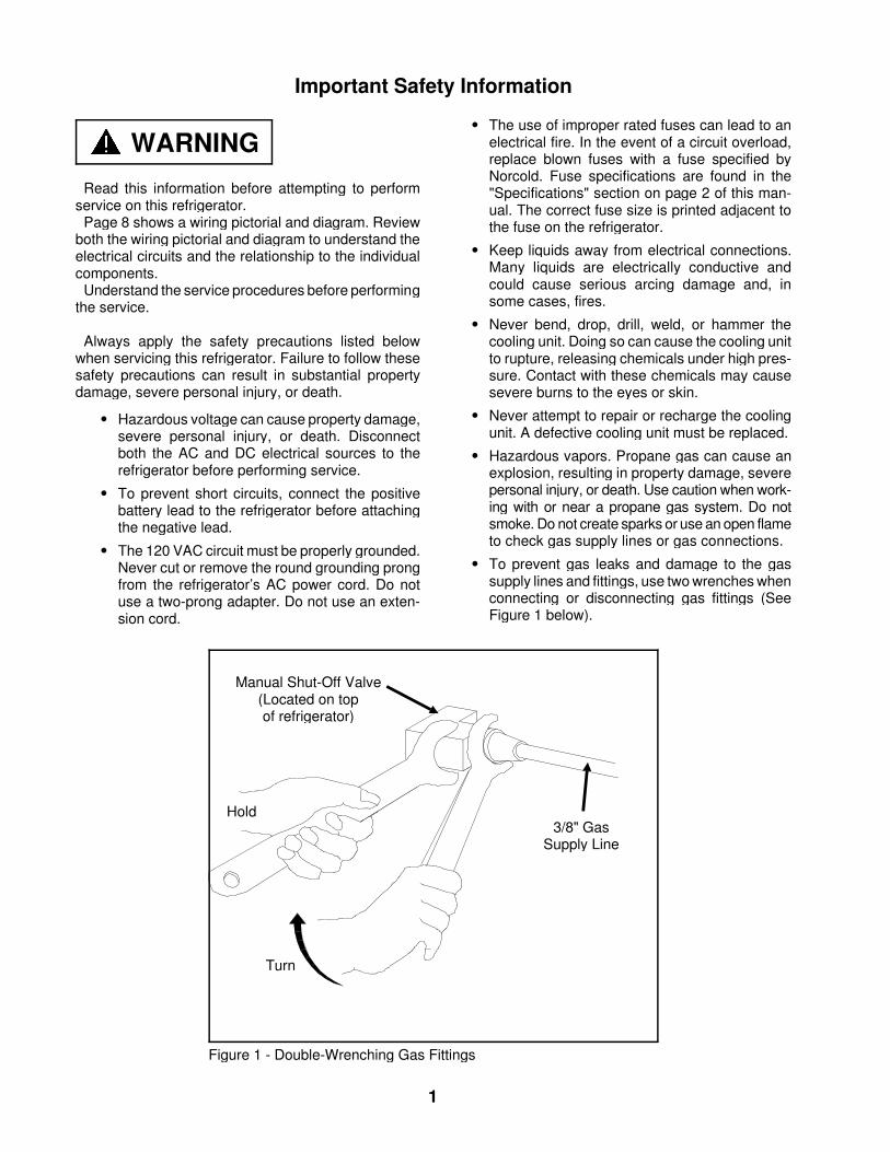
• To prevent gas leaks and damage to the gassupply lines and fittings, use two wrenches whenconnecting or disconnecting gas fittings (SeeFigure 1 below).
Manual Shut-Off Valve(Located on topof refrigerator)
Hold3/8" Gas
Supply Line
Turn
Figure 1 - Double-Wrenching Gas Fittings
WARNING
1
Specifications
Operating LimitsAC Mode: 132 volts AC max. - 108 volts AC min.DC Mode: 15.4 volts DC max. - 11.5 volts DC min.Gas Mode: 11" W.C. max. - 10.5" W.C. min.
15.4 VDC max. - 10.5 VDC min.
Current DrawsAC Heating Element - 1.3 amp @ 110 volts AC
1.4 amps @ 120 volts ACDC Heating Element - 11.7 amps @ 12 volts DC
13.6 amps @ 14 volts DCIgnition Relighter - 150 milliamps during ignition
100 milliamps steady stateVentilation Fan - 240 milliamps
RatingsLP Gas Mode: 640 BTU/Hr. Input
11" W.C. Gas Supply.010" Orifice (LP10)
AC Mode: 110 volts AC - 140 wattsDC Mode: 12 volts DC - 140 watts
Fuse Replacement DataAC Circuit: 3 amp Type 3AG (1/4" x 1/4")
Norcold Part No.: 61654622DC Circuit: 20 amp Type 3AG (1/4" x 1/4")
Norcold Part No.: 61440522Gas Circuit: 1 amp Type 3AG (1/4" x 1/4")
Norcold Part No.: 618079
General Information
This refrigerator is not intended to be operated as aFree-Standing refrigerator (i.e. the products of combus-tion must be completely isolated from the living area)or installed in such a way as to conflict with theseinstallation instructions. Unapproved installations couldresult in safety risks or performance problems.
The model 3163 is designed for built-in installation andoperates on propane gas, 120 volts AC, or 12 volts DC.
The propane gas mode of operation is that of a sealedcombustion unit. A sealed combustion installation util-izes a single fresh vent-air intake/exhaust assembly tosupply fresh air to the burner and to remove the prod-ucts of combustion. This insures the products of com-bustion are isolated from the living area of the vehicle.The vent-air intake/exhaust assembly is routed throughthe vehicle’s outside wall and is connected to therefrigerator’s burner assembly and exhaust flue tube byflexible piping. The vent-air intake/exhaust assemblyused for this installation has been certified for thisrefrigerator and must not be modified.
Direct Vent Requirements
Interior VentilationThe refrigerator’s cooling system requires a continual
air flow to maintain proper refrigeration. An inlet andexhaust vent is required to insure adequate air flow.The refrigerator is equipped with an inlet vent locatedat the bottom front of the refrigerator. The installer isrequired to provide the exhaust vent. The exhaust ventmust have a cross sectional area of 30 square inchesminimum. The exhaust vent is to be installed above thetop surface of the refrigerator so as not to trap hot airgenerated by the cooling unit. The refrigerator isequipped with a DC ventilation fan to assist the air flowacross the refrigerator’s cooling system while operatingthe refrigerator in the Gas mode.
Ventilation FanA thermostat controlled mechanical fan is used to
move air across the refrigerator’s cooling system. The
thermostat is calibrated to activate the fan wheneverthe vehicle’s interior temperature reaches 85 degreesor higher.
When leaving the vehicle unattended, it is advisableto leave windows or roof exhaust vents open to main-tain the vehicle’s interior temperature below 85 de-grees. This will allow the refrigerator to operateefficiently, minimize fan operation, and limit currentdraw from the battery.
Installing the Vent-Air Intake/Exhaust Assy
Improper location and installation can cause injury orproperty damage. This refrigerator and it’s vents aredesign certified by the American Gas Association andthe Canadian Gas Association. Any deviation or sub-
WARNING
WARNING
2
stitution will void the agencies’ certifications and theNorcold warranty. Refer to this manual for proper in-structions. Install the refrigerator and vents as directedby Norcold without modification.
The clearance from the refrigerator’s left side (facingthe front of the refrigerator) to the vehicle’s exterior wallis important. This is the area in which the inlet and outletflexible piping will be connected to the vent terminalhousing during installation. Refer to Figures 3 and 4 formaximum clearances from refrigerator cabinet to vehi-cle exterior wall.
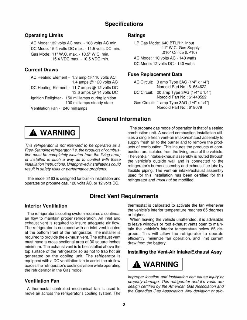
The wall thickness the vent terminal housing willaccommodate is .030" minimum to 1.250" maximum.Figure 2 illustrates the configuration of the opening forthe vent terminal housing. Do not make the opening inthe vehicle wall larger than required. The clearanceshould be enough for the terminal housing to passthrough the opening. If the opening is too large, theouter gasket will not cover the vent housing opening.
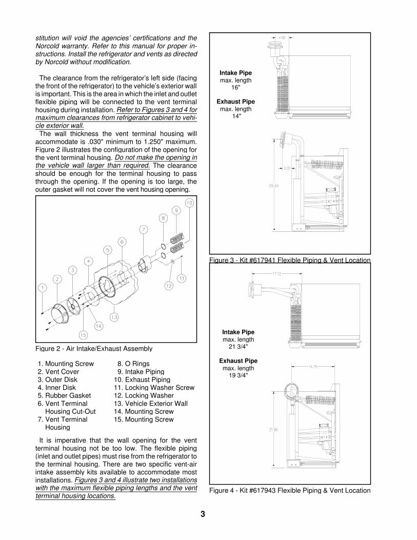
It is imperative that the wall opening for the ventterminal housing not be too low. The flexible piping(inlet and outlet pipes) must rise from the refrigerator tothe terminal housing. There are two specific vent-airintake assembly kits available to accommodate mostinstallations. Figures 3 and 4 illustrate two installationswith the maximum flexible piping lengths and the ventterminal housing locations.
Figure 2 - Air Intake/Exhaust Assembly
Intake Pipemax. length
16"
Exhaust Pipemax. length
14"
Figure 3 - Kit #617941 Flexible Piping & Vent Location
Intake Pipemax. length
21 3/4"
Exhaust Pipemax. length
19 3/4"
Figure 4 - Kit #617943 Flexible Piping & Vent Location
1. Mounting Screw 8. O Rings2. Vent Cover 9. Intake Piping3. Outer Disk 10. Exhaust Piping4. Inner Disk 11. Locking Washer Screw5. Rubber Gasket 12. Locking Washer6. Vent Terminal 13. Vehicle Exterior Wall
Housing Cut-Out 14. Mounting Screw7. Vent Terminal 15. Mounting Screw
Housing
3
Insulating the Flexible Exhaust PipingThe flexible exhaust pipe must be insulated prior to
installation into the vent terminal housing. The flexibleexhaust pipe connects to the flue tube of the refrigera-tor’s cooling unit and routes to the bottom opening ofthe vent terminal housing. Use the non-combustibleinsulation material supplied with the vent-air intake/ex-haust kit. Do not insulate the Air Intake pipe.
Installing Refrigerator into the EnclosureSet the refrigerator into the enclosure and slide it back
enough to connect the gas supply piping to the manualshut-off valve located at the top of the refrigerator.Connect the 12 volt DC supply to the terminal block alsolocated at the top of the refrigerator. Connect the AC
power cord to the receptacle. Place the "O" rings ontothe ends of both flexible pipes. Bend the flexible pipesso they clear the top of the enclosure. Connect thepiping as follows:
Exhaust Pipe - This pipe is insulated and connects tothe flue tube of the cooling unit. Routeand connect to the bottom opening ofthe vent terminal housing.
Intake Pipe - This pipe is not insulated and connects tothe burner cover. Route and connect to thetop opening of the vent terminal housing.
Secure both flexible pipes to vent terminal housingwith locking washer and screw. Slide refrigerator com-pletely into enclosure.
Propane System
Testing of the Vehicle’s Gas Supply PipingWhen installation is complete, the propane gas
supply piping must be inspected and tested for leaksfrom the refrigerator to the main gas supply tank. Usea leak detection solution. Do not test for leaks with anopen flame.
If compressed air is used for leak testing, the pressuremust not exceed 1/2 psig (14 inches water column).
The appliance and its individual shutoff valve must bedisconnected from the gas supply piping system duringany pressure testing of that system at test pressure inexcess of 1/2 psig (14 inches water column).
The appliance must be isolated from the gas supplypiping system by closing its manual shutoff valve duringany pressure testing of the gas supply piping system attest pressure less than or equal to 1/2 psig (14 incheswater column).
Check the gas pressure to the refrigerator withoutother gas appliances operating. The pressure shouldnot exceed 11 inches water column. With other appli-ances operating the pressure should not be less than10.5 inches water column.
Gas Burner FlameThe gas operation of the refrigerator is controlled by
the correct burner flame which supplies the heat inputto the refrigerator’s cooling system. The correct burnerflame is dependent upon correct input gas pressureand the burner and burner orifice being clean. Thepropane gas piping and the supply pressure must beinspected and tested at least twice a year. All inspec-tions and tests must be performed by the propane gassupplier or a qualified service agency.
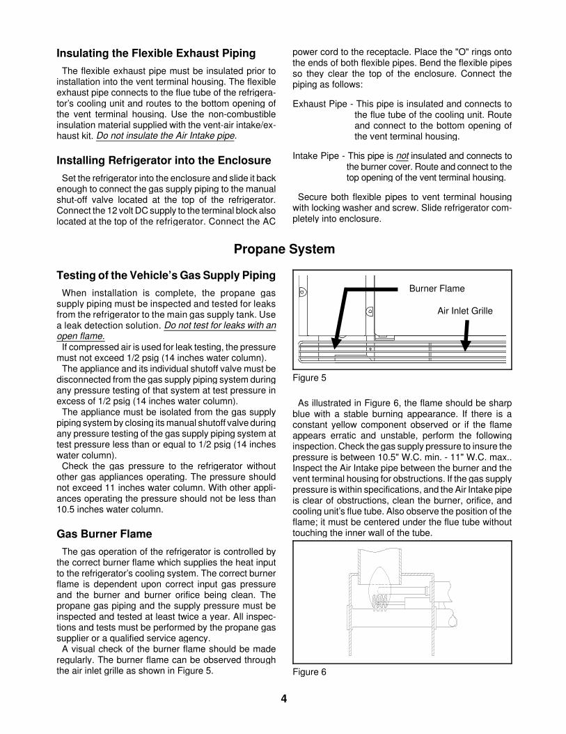
A visual check of the burner flame should be maderegularly. The burner flame can be observed throughthe air inlet grille as shown in Figure 5.
As illustrated in Figure 6, the flame should be sharpblue with a stable burning appearance. If there is aconstant yellow component observed or if the flameappears erratic and unstable, perform the followinginspection. Check the gas supply pressure to insure thepressure is between 10.5" W.C. min. - 11" W.C. max..Inspect the Air Intake pipe between the burner and thevent terminal housing for obstructions. If the gas supplypressure is within specifications, and the Air Intake pipeis clear of obstructions, clean the burner, orifice, andcooling unit’s flue tube. Also observe the position of theflame; it must be centered under the flue tube withouttouching the inner wall of the tube.
Burner Flame
Air Inlet Grille
Figure 5
Figure 6
4
Check Out of Flame Failure Safety Device1. To verify operation of the flame failure safety
device, start the refrigerator in the gas mode(refer to lighting instructions on page 6) and verifythe presence of a flame.
2. Turn off the gas at the manual shut-off valve orat the main gas supply tank.
3. The flame will go out and within 3 minutes the
flame safety device will automatically close (anaudible click will be heard as this device closes).
4. Turn the gas on at the manual shut-off valve.5. Attempt to light the burner by placing the mode
selection button to the gas mode. Do not push inthe safety valve.
6. Without holding the safety valve in, the burnerflame will not re-light. This indicates the flamefailure safety device is functioning.
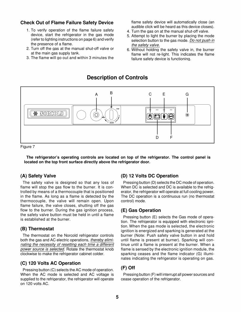
Description of Controls
(A) Safety ValveThe safety valve is designed so that any loss of
flame will stop the gas flow to the burner. It is con-trolled by means of a thermocouple that is positionedin the flame. As long as a flame is detected by thethermocouple, the valve will remain open. Uponflame failure, the valve closes, shutting off the gasflow to the burner. During the gas ignition process,the safety valve button must be held in until a flameis established at the burner.
(B) ThermostatThe thermostat on the Norcold refrigerator controls
both the gas and AC electric operations, thereby elimi-nating the necessity of resetting each time a differentpower source is selected. Rotate the thermostat knobclockwise to make the refrigerator cabinet colder.
(C) 120 Volts AC OperationPressing button (C) selects the AC mode of operation.
When the AC mode is selected and AC voltage issupplied to the refrigerator, the refrigerator will operateon 120 volts AC.
(D) 12 Volts DC OperationPressing button (D) selects the DC mode of operation.
When DC is selected and DC is available to the refrig-erator, the refrigerator will operate at full cooling power.The DC operation is a continuous run (no thermostatcontrol) mode.
(E) Gas OperationPressing button (E) selects the Gas mode of opera-
tion. The refrigerator is equipped with electronic igni-tion. When the gas mode is selected, the electronicignition is energized and sparking is generated at theburner (Note: Push safety valve button in and holduntil flame is present at burner). Sparking will con-tinue until a flame is present at the burner. When aflame is sensed by the electronic ignition module, thesparking ceases and the flame indicator (G) illumi-nates indicating the refrigerator is operating on gas.
(F) OffPressing button (F) will interrupt all power sources and
cease operation of the refrigerator.
A B C
D
E
F
G
Figure 7
The refrigerator’s operating controls are located on top of the refrigerator. The control panel islocated on the top front surface directly above the refrigerator door.
5
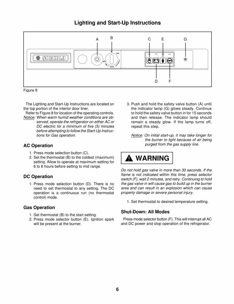
Lighting and Start-Up Instructions
The Lighting and Start-Up Instructions are located onthe top portion of the interior door liner.
Refer to Figure 8 for location of the operating controls.Notice: When warm humid weather conditions are ob-
served, operate the refrigerator on either AC orDC electric for a minimum of five (5) minutesbefore attempting to follow the Start-Up Instruc-tions for Gas operation.
AC Operation1. Press mode selection button (C).2. Set the thermostat (B) to the coldest (maximum)
setting. Allow to operate at maximum setting for6 to 8 hours before setting to mid range.
DC Operation1. Press mode selection button (D). There is no
need to set thermostat to any setting. The DCoperation is a continuous run (no thermostatcontrol) mode.
Gas Operation1. Set thermostat (B) to the start setting.2. Press mode selector button (E). Ignition spark
will be present at the burner.
3. Push and hold the safety valve button (A) untilthe indicator lamp (G) glows steady. Continueto hold the safety valve button in for 15 secondsand then release. The indicator lamp shouldremain a steady glow. If the lamp turns off,repeat this step.
Notice: On initial start-up, it may take longer forthe burner to light because of air beingpurged from the gas supply line.
Do not hold gas valve in more than 30 seconds. If theflame is not indicated within this time, press selectorswitch (F), wait 2 minutes, and retry. Continuing to holdthe gas valve in will cause gas to build up in the burnerarea and can result in an explosion which can causeproperty damage or severe personal injury.
1. Set thermostat to desired temperature setting.
Shut-Down: All ModesPress mode selector button (F). This will interrupt all AC
and DC power and stop operation of the refrigerator.
WARNING
A B C
D
E
F
G
Figure 8
6
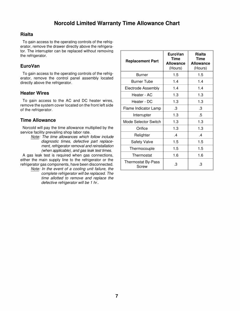
Norcold Limited Warranty Time Allowance Chart
RialtaTo gain access to the operating controls of the refrig-
erator, remove the drawer directly above the refrigera-tor. The interrupter can be replaced without removingthe refrigerator.
EuroVanTo gain access to the operating controls of the refrig-
erator, remove the control panel assembly locateddirectly above the refrigerator.
Heater WiresTo gain access to the AC and DC heater wires,
remove the system cover located on the front left sideof the refrigerator.
Time AllowanceNorcold will pay the time allowance multiplied by the
service facility prevailing shop labor rate.Note: The time allowances which follow include
diagnostic times, defective part replace-ment, refrigerator removal and reinstallation(when applicable), and gas leak test times.
A gas leak test is required when gas connections,either the main supply line to the refrigerator or therefrigerator gas components, have been disconnected.
Note: In the event of a cooling unit failure, thecomplete refrigerator will be replaced. Thetime allotted to remove and replace thedefective refrigerator will be 1 hr..
Replacement Part
EuroVanTime
Allowance(Hours)
RialtaTime
Allowance(Hours)
Burner 1.5 1.5
Burner Tube 1.4 1.4
Electrode Assembly 1.4 1.4
Heater - AC 1.3 1.3
Heater - DC 1.3 1.3
Flame Indicator Lamp .3 .3
Interrupter 1.3 .5
Mode Selector Switch 1.3 1.3
Orifice 1.3 1.3
Relighter .4 .4
Safety Valve 1.5 1.5
Thermocouple 1.5 1.5
Thermostat 1.6 1.6
Thermostat By-PassScrew .3 .3
7
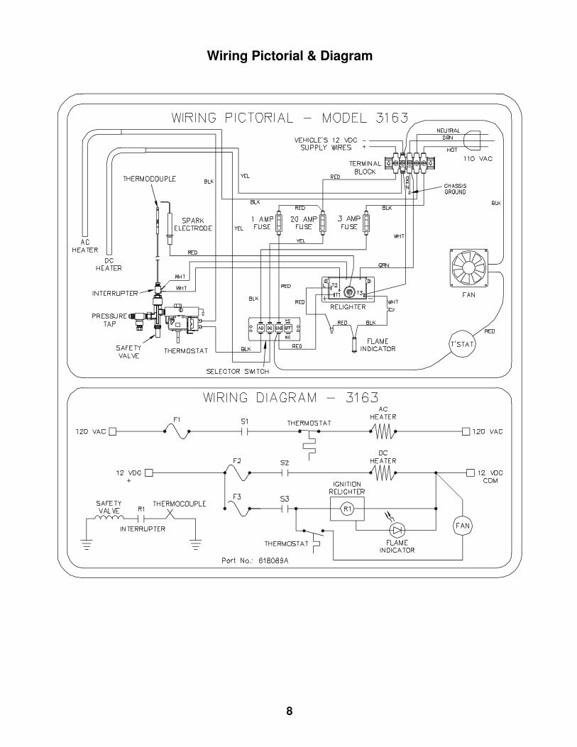
Wiring Pictorial & Diagram
8
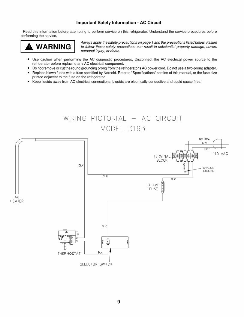
Important Safety Information - AC Circuit
Read this information before attempting to perform service on this refrigerator. Understand the service procedures beforeperforming the service.
• Use caution when performing the AC diagnostic procedures. Disconnect the AC electrical power source to therefrigerator before replacing any AC electrical component.
• Do not remove or cut the round grounding prong from the refrigerator’s AC power cord. Do not use a two-prong adapter.• Replace blown fuses with a fuse specified by Norcold. Refer to "Specifications" section of this manual, or the fuse size
printed adjacent to the fuse on the refrigerator.• Keep liquids away from AC electrical connections. Liquids are electrically conductive and could cause fires.
WARNINGAlways apply the safety precautions on page 1 and the precautions listed below. Failureto follow these safety precautions can result in substantial property damage, severepersonal injury, or death.
9
YES
Is selectorswitch in theAC position?
NO
YES
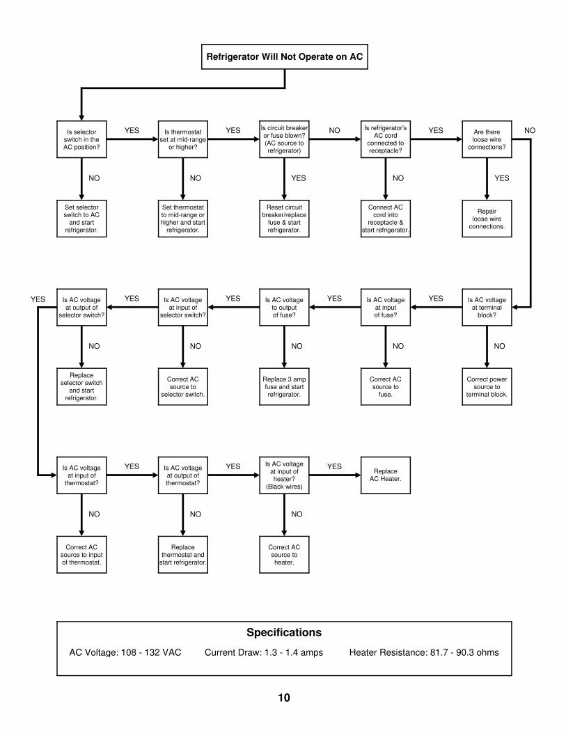
Refrigerator Will Not Operate on AC
Set selectorswitch to AC
and startrefrigerator.
Specifications
AC Voltage: 108 - 132 VAC Current Draw: 1.3 - 1.4 amps Heater Resistance: 81.7 - 90.3 ohms
Is AC voltageat input of
selector switch?
NO
YES
Replaceselector switch
and startrefrigerator.
Is AC voltageat input of
thermostat?
NO
YES
Correct ACsource to inputof thermostat.
ReplaceAC Heater.
Is AC voltageat input ofheater?
(Black wires)
NO
YESIs AC voltageat output ofthermostat?
NO
YES
Correct ACsource toheater.
Replacethermostat and
start refrigerator.
Is AC voltageto outputof fuse?
NO
YES Is AC voltageat inputof fuse?
NO
YES Is AC voltageat terminal
block?
NO
Is AC voltageat output of
selector switch?
NO
YES
Correct powersource to
terminal block.
Correct ACsource to
fuse.
Replace 3 ampfuse and startrefrigerator.
Correct ACsource to
selector switch.
Are thereloose wire
connections?
YES
NOIs refrigerator’sAC cord
connected toreceptacle?
NO
YESIs circuit breakeror fuse blown?(AC source torefrigerator)
YES
NOIs thermostatset at mid-range
or higher?
NO
YES
Repairloose wire
connections.
Connect ACcord into
receptacle &start refrigerator.
Reset circuitbreaker/replace
fuse & startrefrigerator.
Set thermostatto mid-range orhigher and start
refrigerator.
10
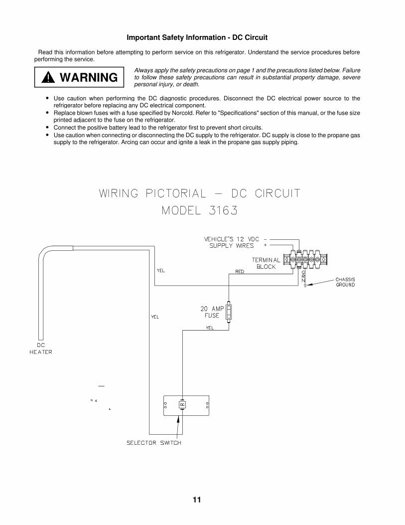
Important Safety Information - DC Circuit
Read this information before attempting to perform service on this refrigerator. Understand the service procedures beforeperforming the service.
• Use caution when performing the DC diagnostic procedures. Disconnect the DC electrical power source to therefrigerator before replacing any DC electrical component.
• Replace blown fuses with a fuse specified by Norcold. Refer to "Specifications" section of this manual, or the fuse sizeprinted adjacent to the fuse on the refrigerator.
• Connect the positive battery lead to the refrigerator first to prevent short circuits.• Use caution when connecting or disconnecting the DC supply to the refrigerator. DC supply is close to the propane gas
supply to the refrigerator. Arcing can occur and ignite a leak in the propane gas supply piping.
WARNINGAlways apply the safety precautions on page 1 and the precautions listed below. Failureto follow these safety precautions can result in substantial property damage, severepersonal injury, or death.
11
Specifications
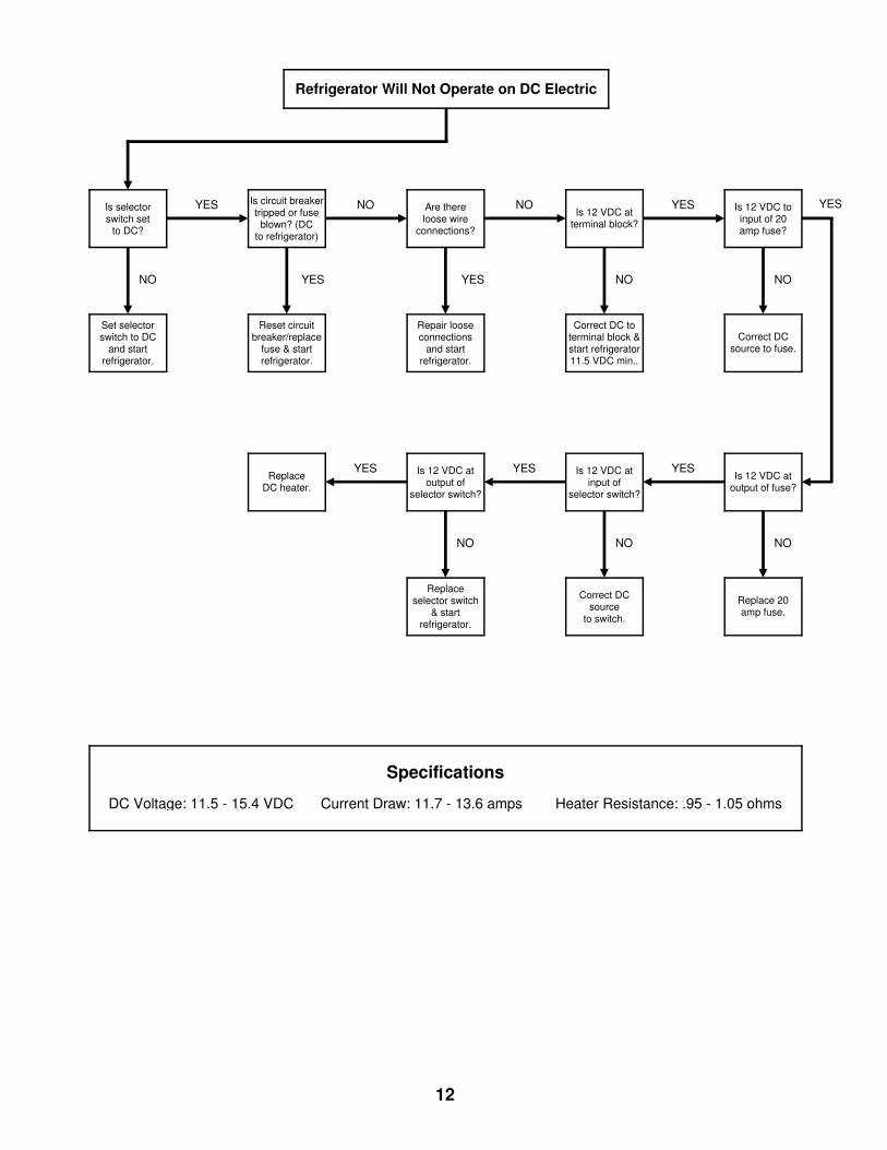
DC Voltage: 11.5 - 15.4 VDC Current Draw: 11.7 - 13.6 amps Heater Resistance: .95 - 1.05 ohms
Refrigerator Will Not Operate on DC Electric
Is selectorswitch set
to DC?
NO
YES
Set selectorswitch to DC
and startrefrigerator.
Is 12 VDC toinput of 20amp fuse?
NO
YES
Is 12 VDC atoutput of fuse?
NO
Replace 20amp fuse.
Correct DCsource to fuse.
ReplaceDC heater.
YES Is 12 VDC atoutput of
selector switch?
NO
YES Is 12 VDC atinput of
selector switch?
NO
YES
Correct DCsource
to switch.
Replaceselector switch
& startrefrigerator.
Is 12 VDC atterminal block?
NO
YESAre thereloose wire
connections?
YES
NOIs circuit breakertripped or fuse
blown? (DCto refrigerator)
YES
NO
Correct DC toterminal block &start refrigerator11.5 VDC min..
Repair looseconnections
and startrefrigerator.
Reset circuitbreaker/replace
fuse & startrefrigerator.
12
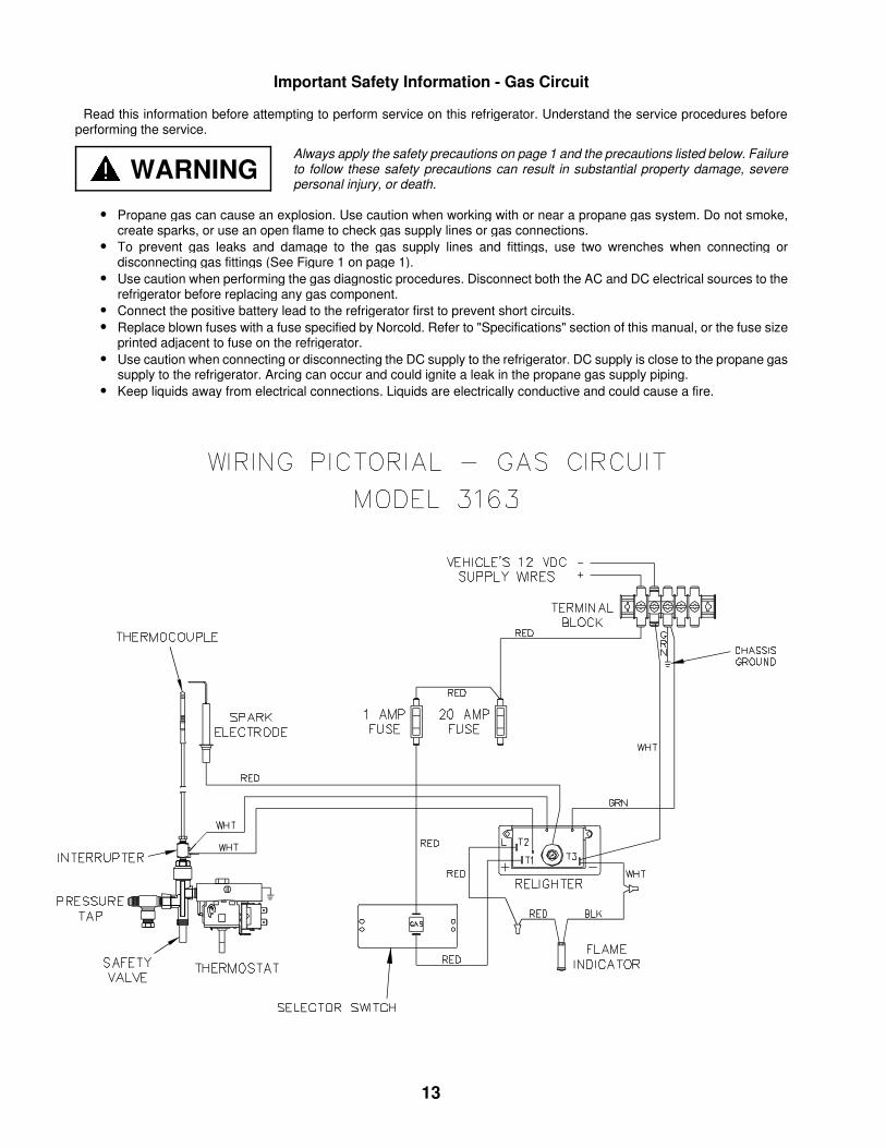
Important Safety Information - Gas Circuit
Read this information before attempting to perform service on this refrigerator. Understand the service procedures beforeperforming the service.
• Propane gas can cause an explosion. Use caution when working with or near a propane gas system. Do not smoke,create sparks, or use an open flame to check gas supply lines or gas connections.
• To prevent gas leaks and damage to the gas supply lines and fittings, use two wrenches when connecting ordisconnecting gas fittings (See Figure 1 on page 1).
• Use caution when performing the gas diagnostic procedures. Disconnect both the AC and DC electrical sources to therefrigerator before replacing any gas component.
• Connect the positive battery lead to the refrigerator first to prevent short circuits.• Replace blown fuses with a fuse specified by Norcold. Refer to "Specifications" section of this manual, or the fuse size
printed adjacent to fuse on the refrigerator.• Use caution when connecting or disconnecting the DC supply to the refrigerator. DC supply is close to the propane gas
supply to the refrigerator. Arcing can occur and could ignite a leak in the propane gas supply piping.• Keep liquids away from electrical connections. Liquids are electrically conductive and could cause a fire.
WARNINGAlways apply the safety precautions on page 1 and the precautions listed below. Failureto follow these safety precautions can result in substantial property damage, severepersonal injury, or death.
13
YES
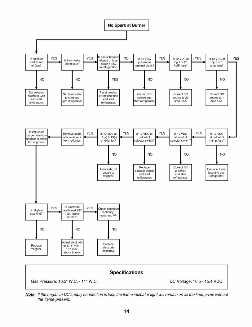
No Spark at Burner
Is 12 VDC atinput of 1
amp fuse?
NO
YES
Is 12 VDCat output of1 amp fuse?
NO
Replace 1 ampfuse and startrefrigerator.
Correct DCsource to 1amp fuse.
Is selectorswitch setto Gas?
NO
YES
Set selectorswitch to Gas
and startrefrigerator.
Is 12 VDC atinput of 20AMP fuse?
NO
YES
Correct DCsource to 20amp fuse.
Is 12 VDCpresent at
terminal block?
NO
YES
Correct DCsource and
start refrigerator.
Is circuit breakertripped or fuse
blown? (DCto refrigerator)
YES
NO
Reset breakeror replace fuse
and startrefrigerator.
Is thermostatset to start?
NO
YES
Set thermostatto start and
light refrigerator.
Is 12 VDC atoutput of
selector switch?
NO
YES
Establish DCsupply torelighter.
Replaceselector switch
and startrefrigerator.
Remove sparkelectrode wirefrom relighter.
YES Is 12 VDC atT1(+) & T3(-)of relighter?
NO
YES
Check electrodecontinuity -
must read ∞.
NO
Replaceelectrodeassembly
Is relightersparking?
NO
YES Is electrodepositioned 1/8"
max. aboveburner?
NO
YES
Replacerelighter.
Adjust electrodeto 1/16" min. -
1/8" max.above burner.
Specifications
Gas Pressure: 10.5" W.C. - 11" W.C. DC Voltage: 10.5 - 15.4 VDC
Install shortjumper wire fromrelighter to within1/8" of ground
Note: If the negative DC supply connection is lost, the flame indicator light will remain on all the time, even withoutthe flame present.
Is 12 VDCat input of
selector switch?
NO
Correct DCto switchand start
refrigerator.
14
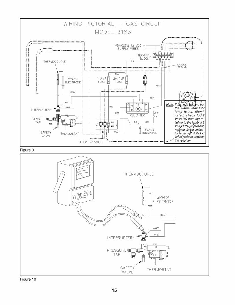
Figure 9
Note: If flame is burning butthe flame indicatorlamp is not i l lumi-nated, check for 2Volts DC from the re-lighter to the lamp. If 2Volts DC is present,replace flame indica-tor lamp. If 2 Volts DCis not present, replacethe relighter.
Figure 10
15
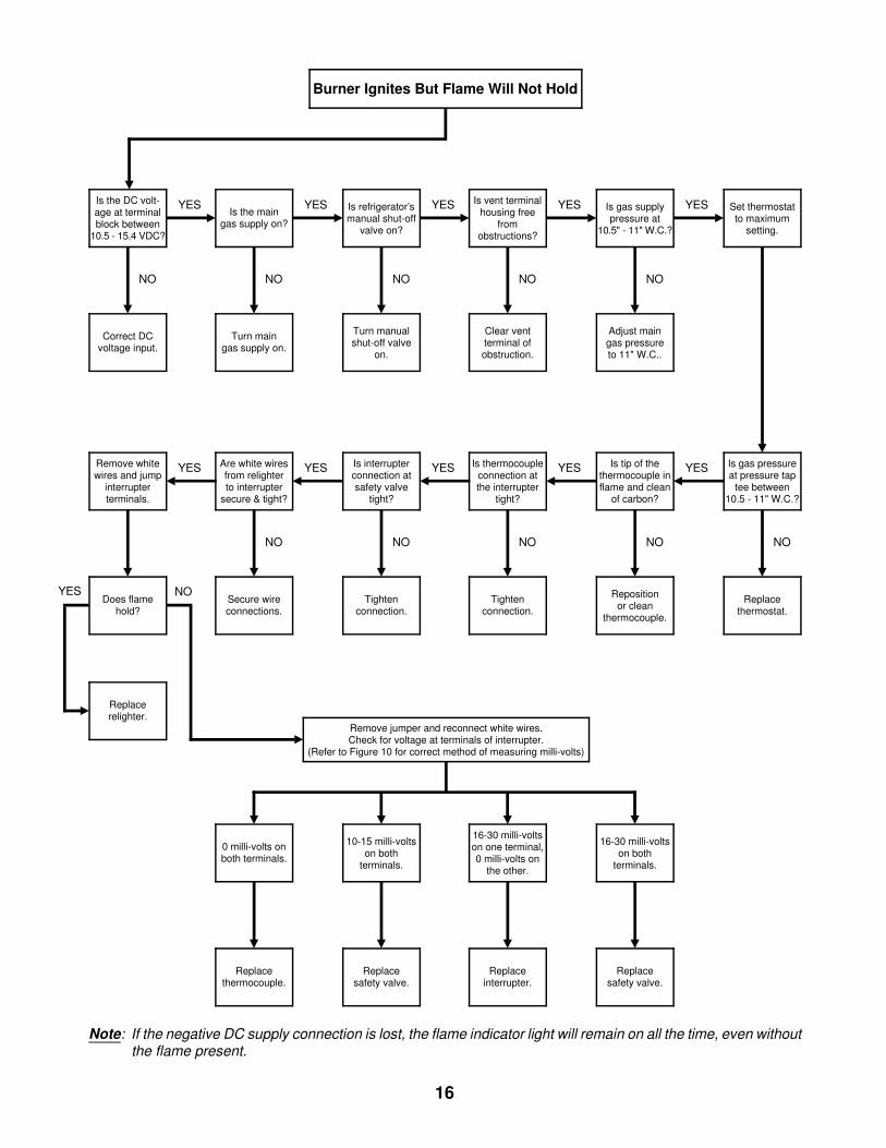
Burner Ignites But Flame Will Not Hold
Set thermostatto maximum
setting.
Is gas pressureat pressure tap
tee between10.5 - 11" W.C.?
NO
Replacethermostat.
Is the DC volt-age at terminalblock between
10.5 - 15.4 VDC?
NO
YES
Correct DCvoltage input.
0 milli-volts onboth terminals.
Replacethermocouple.
Remove whitewires and jump
interrupterterminals.
YES
Tightenconnection.
Secure wireconnections.
Does flamehold?
YES NO
Remove jumper and reconnect white wires.Check for voltage at terminals of interrupter.
(Refer to Figure 10 for correct method of measuring milli-volts)
16-30 milli-voltson both
terminals.
16-30 milli-voltson one terminal,0 milli-volts on
the other.
10-15 milli-voltson both
terminals.
Replacesafety valve.
Replaceinterrupter.
Replacesafety valve.
Note: If the negative DC supply connection is lost, the flame indicator light will remain on all the time, even withoutthe flame present.
Is gas supplypressure at
10.5" - 11" W.C.?
NO
YES
Adjust maingas pressureto 11" W.C..
Is vent terminalhousing free
fromobstructions?
NO
YES
Clear ventterminal ofobstruction.
Is refrigerator’smanual shut-off
valve on?
NO
YES
Turn manualshut-off valve
on.
Is the maingas supply on?
NO
YES
Turn maingas supply on.
Is tip of thethermocouple inflame and clean
of carbon?
NO
YES
Tightenconnection.
Repositionor clean
thermocouple.
Is thermocoupleconnection atthe interrupter
tight?
NO
YESIs interrupterconnection atsafety valve
tight?
NO
YESAre white wiresfrom relighterto interrupter
secure & tight?
NO
YES
Replacerelighter.
16
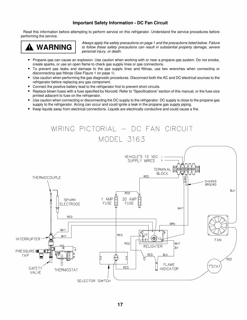
Important Safety Information - DC Fan Circuit
Read this information before attempting to perform service on this refrigerator. Understand the service procedures beforeperforming the service.
• Propane gas can cause an explosion. Use caution when working with or near a propane gas system. Do not smoke,create sparks, or use an open flame to check gas supply lines or gas connections.
• To prevent gas leaks and damage to the gas supply lines and fittings, use two wrenches when connecting ordisconnecting gas fittings (See Figure 1 on page 1).
• Use caution when performing the gas diagnostic procedures. Disconnect both the AC and DC electrical sources to therefrigerator before replacing any gas component.
• Connect the positive battery lead to the refrigerator first to prevent short circuits.• Replace blown fuses with a fuse specified by Norcold. Refer to "Specifications" section of this manual, or the fuse size
printed adjacent to fuse on the refrigerator.• Use caution when connecting or disconnecting the DC supply to the refrigerator. DC supply is close to the propane gas
supply to the refrigerator. Arcing can occur and could ignite a leak in the propane gas supply piping.• Keep liquids away from electrical connections. Liquids are electrically conductive and could cause a fire.
WARNINGAlways apply the safety precautions on page 1 and the precautions listed below. Failureto follow these safety precautions can result in substantial property damage, severepersonal injury, or death.
17
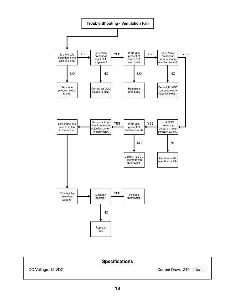
Correct 12 VDCsource to modeselection switch.
Is 12 VDCpresent atoutput of 1amp fuse?
NO
YES
Replace 1amp fuse.
Is 12 VDCpresent atinput of 1
amp fuse?
NO
YES
Correct 12 VDCsource to fuse.
Is the modeselection in theGas position?
NO
YES
Set modeselection switch
to gas.
Correct 12 VDCsource to fanthermostat.
Replace modeselection switch.
Is 12 VDCpresent at
fan thermostat?
NO
YES
Connect thetwo wirestogether.
Does fanoperate?
NO
YES
Disconnect redwire from modeselection switchto thermostat.
YES
Replacethermostat.
Disconnect redwire from fanto thermostat.
Replacefan.
Is 12 VDCpresent at
input of modeselection switch?
NO
YES
Is 12 VDCpresent at
output of modeselection switch?
NO
Trouble Shooting - Ventilation Fan
Specifications
DC Voltage: 12 VDC Current Draw: .240 milliamps
18
Diagnosing Cooling Problems
Read this information before attempting to performservice on this refrigerator. Understand the serviceprocedures before performing the service.
Always apply the safety precautions on page 1 and theprecautions listed below. Failure to follow these safetyprecautions can result in substantial property damage,severe personal injury, or death.
• Never bend, drop, drill, weld, or hammer thecooling unit. Doing so can cause the cooling unitto rupture, releasing chemicals under high pres-sure. Contact with these chemicals may causesevere burns to the eyes or skin.
• Never attempt to repair or recharge the coolingunit. A defective cooling unit must be replaced.
Diagnostic Procedures1. Make sure the cooling problem occurs while op-
erating the refrigerator in each mode of opera-tion. If not, the cooling problem is not the coolingunit. Refer to Trouble Shooting sections to deter-mine cause for insufficient cooling on identifiedmode of operation.
2. Make sure the interior venting is not obstructedand is providing air circulation across the coolingunit’s absorber coils and condenser fins.
3. Make sure the 12 VDC ventilation fan is func-tional. The fan will operate whenever the vehi-cle’s interior temperature reaches 85° or higher.
See pictorial and trouble shooting guide onpages 17 & 18.
4. An off-level situation, if the infraction is marginal,will allow the refrigerator to continue to operateat a reduced level of cooling until the refrigeratoris leveled. Greater off-level situations will stop therefrigerant circulation and cease cooling. Normalvehicle leveling to provide comfort for the occu-pants is within the refrigerator’s operating limits.The refrigerator’s operating limits are 3 degreesoff-level front-to-back and 6 degrees off-levelside-to-side. Operating the refrigerator outside ofthese operating limits for an extended time willcause irreparable damage to the cooling unit.
5. Check the input voltages and gas pressure toinsure correct heat input and voltage limits.The specifications are as follows:
a. 120 VAC - 108 VAC min. to 132 VAC max.b. 12 VDC - 11.5 VDC min. to 15.4 VDC max.c. Gas - 10.5" W.C. min. to 11" W.C.
Correct input voltages and propane gas supplyare critical for the cooling unit to function properly.
6. Check the area of the cooling unit for refrigerantleaks. The smell of ammonia is a positive sign ofa refrigerant leak. When an ammonia smell isdetected, the cooling unit must be replaced. An-other sign of a refrigerant leak is the appearanceof a yellow powder in the vicinity of the coolingunit. When this powder is observed, the coolingunit must be replaced.
7. Check the absorber coils; the bottom coil will bewarm and the top coil will be cooler. If the coilsare cold and the cooling units flue enclosure istoo hot to touch, there is a blockage in the coolingunit and the cooling unit must be replaced.
WARNING
19
Refrigerator Removal Procedures
Improper removal and installation of the refrigeratorcan cause injury or property damage. Before attempt-ing the procedures below, review the "Important SafetyInformation" on page 1 and the procedures below.
EuroVan Camper1. Turn off the gas supply at the main tank.2. Turn the refrigerator’s mode selector to "OFF".3. Remove the vehicle’s middle bench seat.4. Remove the refrigerator’s system cover located
on the left front of the refrigerator by removing 5retaining screws.
5. Remove 5 retaining screws securing refrigeratorto enclosure.
6. Remove the monitor panel located directly abovethe refrigerator by removing 6 retaining screws.CAUTION: It is not necessary to disconnect
wiring from the monitor panel. Pullpanel forward and away from themonitor panel’s mounting bracket.Lay monitor panel on galley top.Take care not to scratch the galleyand its surrounding surfaces, orthe face of the control panel.
7. Remove the monitor panel’s mounting (frame)bracket by removing four retaining screws. Theretaining screws are located on both the left andright sides of the bracket.
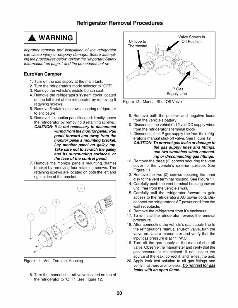
8. Turn the manual shut-off valve located on top ofthe refrigerator to "OFF". See Figure 12.
9. Remove both the positive and negative leadsfrom the vehicle’s battery.
10. Disconnect the vehicle’s 12 volt DC supply wiresfrom the refrigerator’s terminal block.
11. Disconnect the LP gas supply line from the refrig-erator’s manual shut-off valve. See Figure 12.CAUTION: To prevent gas leaks or damage to
the gas supply lines and fittings,use two wrenches when connect-ing or disconnecting gas fittings.
12. Remove the three (3) screws securing the ventcover to the vehicle’s exterior surface. SeeFigure 11.
13. Remove the two (2) screws securing the innerdisk to the vent terminal housing. See Figure 11.
14. Carefully push the vent terminal housing inwarduntil free from the vehicle’s wall.
15. Carefully pull the refrigerator forward to gainaccess to the refrigerator’s AC power cord. Dis-connect the refrigerator’s AC power cord from thewall receptacle.
16. Remove the refrigerator from it’s enclosure.17. To re-install the refrigerator, reverse the removal
procedure.18. After connecting the vehicle’s gas supply line to
the refrigerator’s manual shut-off valve, turn thevalve on. Use a manometer and verify that theinput gas pressure is at 11" W.C..
19. Turn off the gas supply at the manual shut-offvalve. Observe the manometer and verify that thegas pressure is maintained. If not, locate thesource of the leak, correct it, and re-test the unit.
20. Apply leak test solution to all gas fittings andverify that there are no leaks. Do not test for gasleaks with an open flame.
Valve Shown inOff Position
LP GasSupply Line
U-Tube toThermostat
Figure 12 - Manual Shut-Off Valve
Figure 11 - Vent Terminal Housing
WARNING
20
Rialta1. Turn off the gas supply at the main tank.2. Turn the refrigerator’s mode selector to "OFF".3. Remove the refrigerator’s system cover located
on the left front of the refrigerator by removing 5retaining screws.
4. Remove 5 retaining screws securing the refrig-erator to the enclosure.
5. Remove the drawer directly above the refrigerator.6. Turn the manual shut-off valve located on top of
the refrigerator to "OFF". See Figure 12.7. Disconnect the vehicle’s 12 volt DC supply wires
from the refrigerator’s terminal block.8. Disconnect the LP gas supply line from the refrig-
erator’s manual shut-off valve. See Figure 12.CAUTION: To prevent gas leaks and damage to
the gas supply lines and fittings,use two wrenches when connect-ing or disconnecting gas fittings.
9. Disconnect the refrigerator’s AC power cord fromthe wall receptacle.
10. Open the cabinet door to the left of the refrigera-tor. Remove the access panel at the rear of thecabinet. This will allow access to the refrigerator’svent-air intake and exhaust piping.
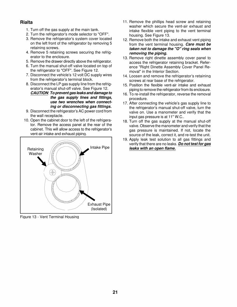
11. Remove the phillips head screw and retainingwasher which secure the vent-air exhaust andintake flexible vent piping to the vent terminalhousing. See Figure 13.
12. Remove both the intake and exhaust vent pipingfrom the vent terminal housing. Care must betaken not to damage the "O" ring seals whenremoving the piping.
13. Remove right dinette assembly cover panel toaccess the refrigerator retaining bracket. Refer-ence "Right Dinette Assembly Cover Panel Re-moval" in the Interior Section.
14. Loosen and remove the refrigerator’s retainingscrews at rear base of the refrigerator.
15. Position the flexible vent-air intake and exhaustpiping to remove the refrigerator from its enclosure.
16. To re-install the refrigerator, reverse the removalprocedure.
17. After connecting the vehicle’s gas supply line tothe refrigerator’s manual shut-off valve, turn thevalve on. Use a manometer and verify that theinput gas pressure is at 11" W.C..
18. Turn off the gas supply at the manual shut-offvalve. Observe the manometer and verify that thegas pressure is maintained. If not, locate thesource of the leak, correct it, and re-test the unit.
19. Apply leak test solution to all gas fittings andverify that there are no leaks. Do not test for gasleaks with an open flame.Intake Pipe
Exhaust Pipe(Isolated)
RetainingWasher
Figure 13 - Vent Terminal Housing
21
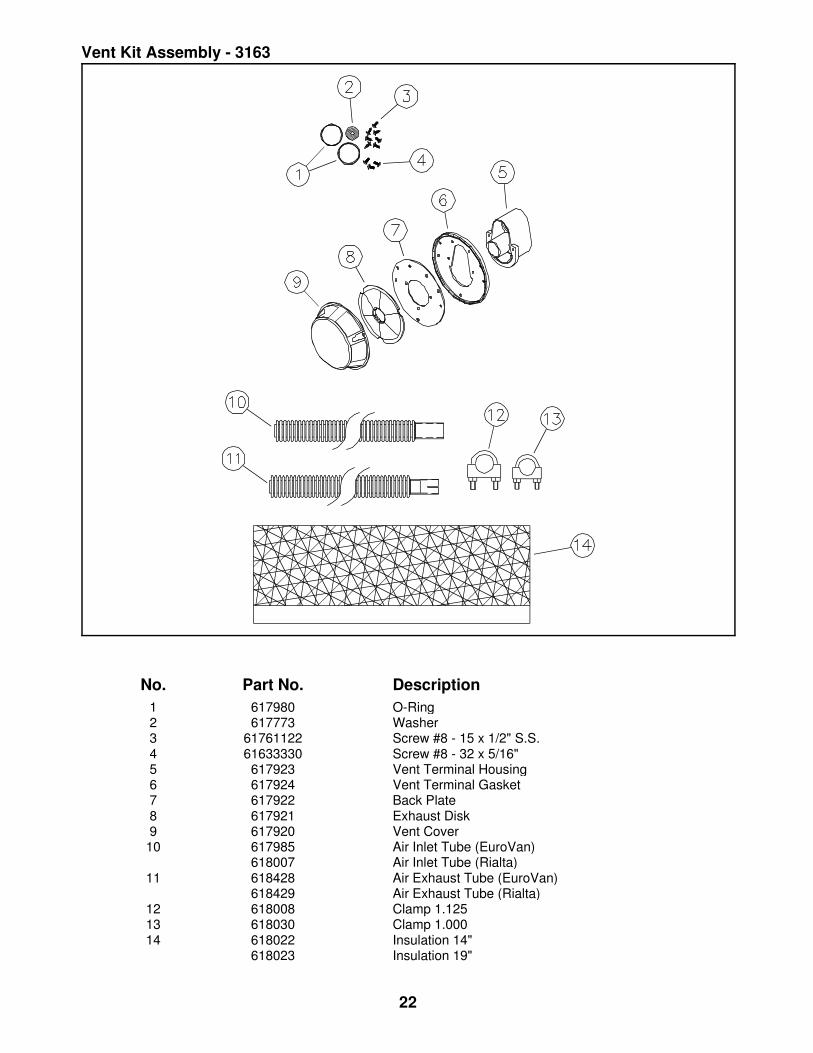
No. Part No. Description1 617980 O-Ring2 617773 Washer3 61761122 Screw #8 - 15 x 1/2" S.S.4 61633330 Screw #8 - 32 x 5/16"5 617923 Vent Terminal Housing6 617924 Vent Terminal Gasket7 617922 Back Plate8 617921 Exhaust Disk9 617920 Vent Cover10 617985 Air Inlet Tube (EuroVan)
618007 Air Inlet Tube (Rialta)11 618428 Air Exhaust Tube (EuroVan)
618429 Air Exhaust Tube (Rialta)12 618008 Clamp 1.12513 618030 Clamp 1.00014 618022 Insulation 14"
618023 Insulation 19"
Vent Kit Assembly - 3163
22
Final Assembly - 3163
23
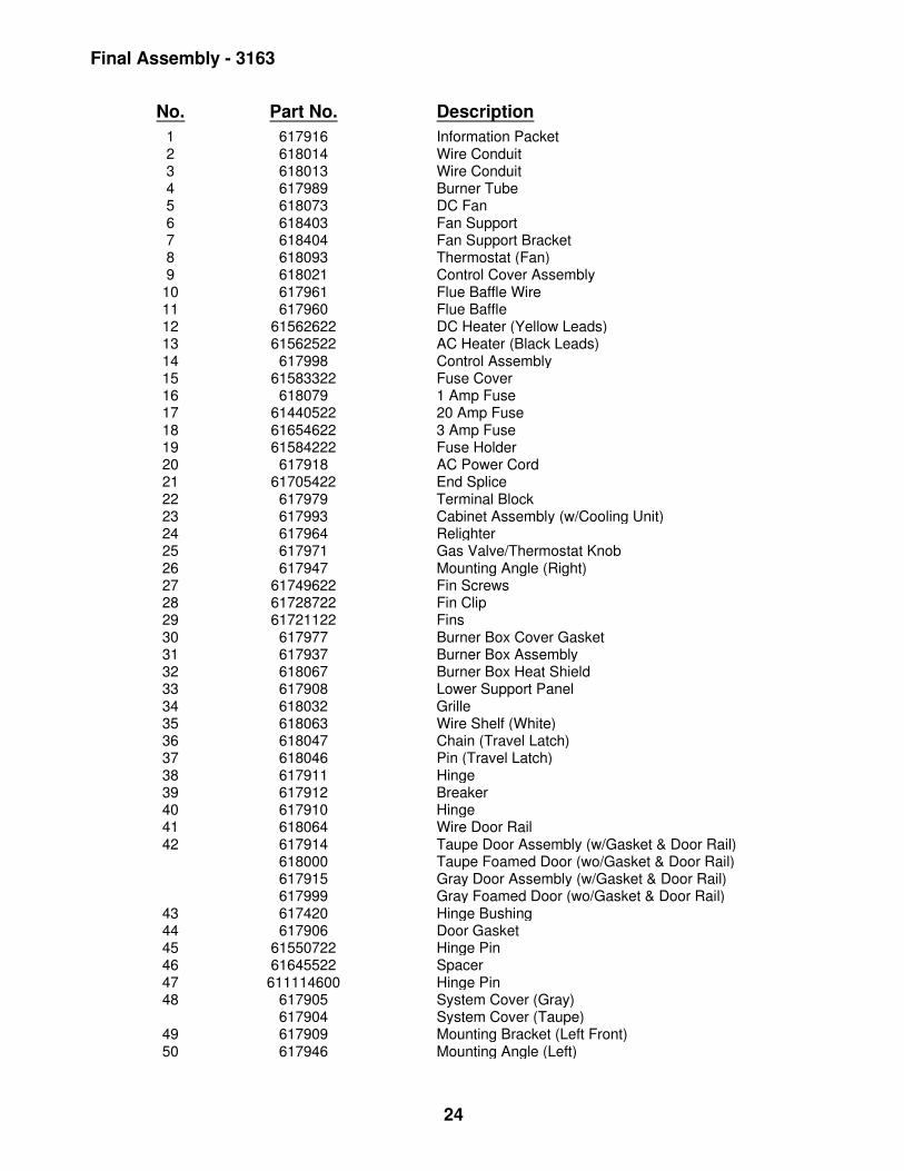
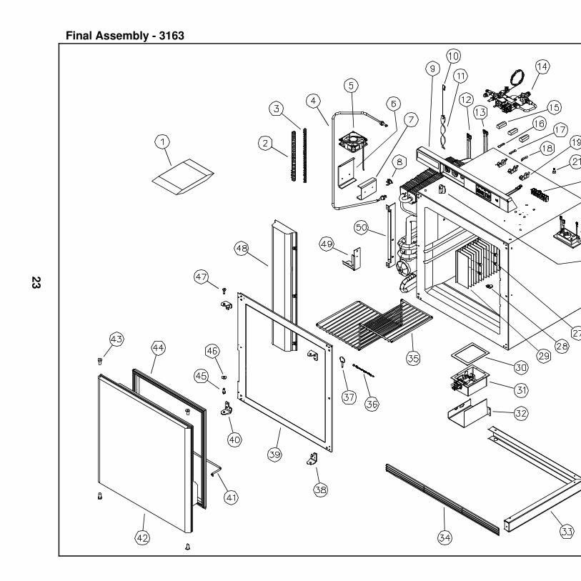
No. Part No. Description1 617916 Information Packet2 618014 Wire Conduit3 618013 Wire Conduit4 617989 Burner Tube5 618073 DC Fan6 618403 Fan Support7 618404 Fan Support Bracket8 618093 Thermostat (Fan)9 618021 Control Cover Assembly10 617961 Flue Baffle Wire11 617960 Flue Baffle12 61562622 DC Heater (Yellow Leads)13 61562522 AC Heater (Black Leads)14 617998 Control Assembly15 61583322 Fuse Cover16 618079 1 Amp Fuse17 61440522 20 Amp Fuse18 61654622 3 Amp Fuse19 61584222 Fuse Holder20 617918 AC Power Cord21 61705422 End Splice22 617979 Terminal Block23 617993 Cabinet Assembly (w/Cooling Unit)24 617964 Relighter25 617971 Gas Valve/Thermostat Knob26 617947 Mounting Angle (Right)27 61749622 Fin Screws28 61728722 Fin Clip29 61721122 Fins30 617977 Burner Box Cover Gasket31 617937 Burner Box Assembly32 618067 Burner Box Heat Shield33 617908 Lower Support Panel34 618032 Grille35 618063 Wire Shelf (White)36 618047 Chain (Travel Latch)37 618046 Pin (Travel Latch)38 617911 Hinge39 617912 Breaker40 617910 Hinge41 618064 Wire Door Rail42 617914 Taupe Door Assembly (w/Gasket & Door Rail)
618000 Taupe Foamed Door (wo/Gasket & Door Rail)617915 Gray Door Assembly (w/Gasket & Door Rail)617999 Gray Foamed Door (wo/Gasket & Door Rail)
43 617420 Hinge Bushing44 617906 Door Gasket45 61550722 Hinge Pin46 61645522 Spacer47 611114600 Hinge Pin48 617905 System Cover (Gray)
617904 System Cover (Taupe)49 617909 Mounting Bracket (Left Front)50 617946 Mounting Angle (Left)
Final Assembly - 3163
24
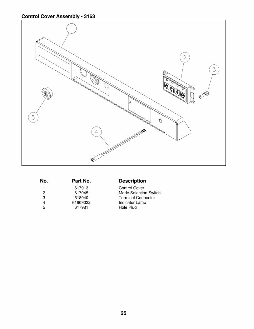
No. Part No. Description1 617913 Control Cover2 617945 Mode Selection Switch3 618040 Terminal Connector4 61609022 Indicator Lamp5 617981 Hole Plug
Control Cover Assembly - 3163
25
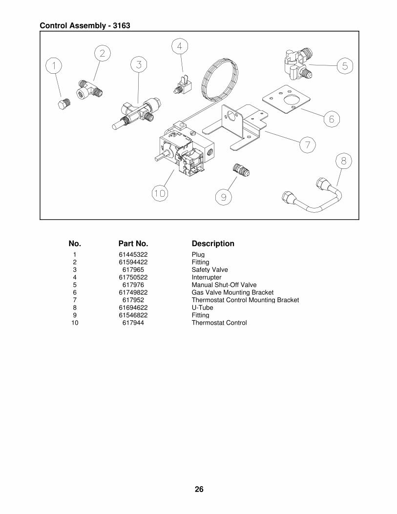
No. Part No. Description1 61445322 Plug2 61594422 Fitting3 617965 Safety Valve4 61750522 Interrupter5 617976 Manual Shut-Off Valve6 61749822 Gas Valve Mounting Bracket7 617952 Thermostat Control Mounting Bracket8 61694622 U-Tube9 61546822 Fitting10 617944 Thermostat Control
Control Assembly - 3163
26
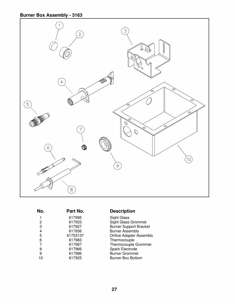
No. Part No. Description1 617995 Sight Glass2 617933 Sight Glass Grommet3 617927 Burner Support Bracket4 617936 Burner Assembly5 61753137 Orifice Adapter Assembly6 617983 Thermocouple7 617997 Thermocouple Grommet8 617966 Spark Electrode9 617996 Burner Grommet10 617925 Burner Box Bottom
Burner Box Assembly - 3163
27
����������� ������ �������������� ��� ���������������
�������������� �� �� ����� �� � �� ����������������������������� �������������
� ��� ������������� ��������� ���� ���������������� ������������� ��� �� ��� �� �������� ����� ���������� ��������� ������������������������ ����� ��� �������������������������� ������� ������ ��� ��� ����������� !"��� � ������������������ ��� � !����������������#$%�&����� '����� ���
(����������������������� �������&� �� ����� ����������'�
��������������