Embed Size (px)
Citation preview

DELUXE HIGH WALL MINI SPLITSERVICE MANUAL
MODEL : HMH009KD1 / HMC009KD1HMH012KD1 / HMC012KD1HMH018KD1 / HMC018KD1HMH024KD1 / HMC024KD1
CAUTION
-BEFORE SERVICING THE UNIT, READ THE "SAFETYPRECAUTIONS" IN THIS MANUAL.-ONLY FOR AUTHORIZED SERVICE PERSONNEL.
International Comfort Products

Functions ...................................................................................................................................... 3
Product Specifications ................................................................................................................ 5
Dimensions................................................................................................................................... 7
Refrigeration Cycle Diagram..................................................................................................... 10
Wiring Diagram .......................................................................................................................... 12
Operation Details ....................................................................................................................... 15
Display Function ........................................................................................................................ 22
Self-diagnosis Function ............................................................................................................ 22
Installation .................................................................................................................................. 23
Operation .................................................................................................................................... 38
Disassembly of the Parts(Indoor Unit)..................................................................................... 40
Cycle Troubleshooting Guide ................................................................................................... 46
Electronic Control Device ......................................................................................................... 56
Schematic Diagram.................................................................................................................... 59
Exploded View and Replacement Parts List............................................................................ 60
- 2 -
Contents

- 3 -
Functions
Indoor Unit
Operation ON/OFF by Remote controller
Sensing the Room Temperature
Room temperature control
Starting Current Control
Time Delay Safety Control
Indoor Fan Speed Control
Operation indication Lamps (LED)
Healthy Dehumidification Mode
Sleep Mode Auto Control
Auto Air Control by the unit electronic control
Chaos Swing
Defrost control(Heating)
Hot-start Control (Heating)
• Room temperature sensor (THERMISTOR)
• Maintains the room temperature in accordance with the Setting Temp.
• Indoor fan is delayed for 5 seconds at the starting.
• Restarting is inhibited for approx. 3 minutes.
• High, Med, Low and Auto
• Intermittent operation of fan at low speed
• Both the indoor and outdoor fan stopsduring defrosting.
• Hot start wil l be operated afterdefrosting ends.
• The indoor fan stops until the indoor pipe temperature will bereached at 28°C(82°F).
• The fan is switched to low(Cooling), med(Heating) speed.• The unit will be stopped after 1, 2, 3, 4, 5, 6, 7 hours.
• The fan is switched to intermittent or irregular operation.• The fan speed is automatically switched from high to low speed.
• The louver can be set at the desired position or swing upand down automatically.
--- Lights up in operation
--- Lights up in Sleep Mode
--- Lights up in Timer Mode
--- Lights up in Defrost Mode or Hot Start Mode (only Heating Model)
--- Lights up during compressor running (only Cooling Model)OUTDOOR
- 4 -
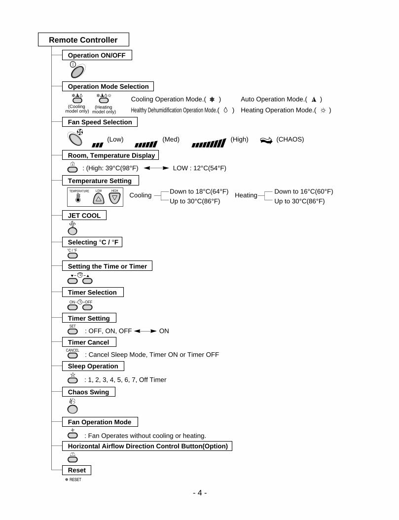
Healthy Dehumidification Operation Mode.( )
Remote Controller
Operation ON/OFF
Reset
Operation Mode Selection
Temperature Setting
Timer Selection
Timer Setting
JET COOL
Timer Cancel
Sleep Operation
Chaos Swing
(Cooling model only)
(Heating model only)
TEMPERATURE LOW HIGH
Cooling Operation Mode.( )
Heating Operation Mode.( )
Auto Operation Mode.( )
Fan Operation Mode
Horizontal Airflow Direction Control Button(Option)
Room, Temperature Display
Setting the Time or Timer
Selecting °C / °F
ON OFF
SET
°C / °F
CANCEL
Fan Speed Selection
(Low) (Med) (High) (CHAOS)
: (High: 39°C(98°F) LOW : 12°C(54°F)
Down to 18°C(64°F)
Up to 30°C(86°F)Cooling
: OFF, ON, OFF ON
: Cancel Sleep Mode, Timer ON or Timer OFF
: 1, 2, 3, 4, 5, 6, 7, Off Timer
: Fan Operates without cooling or heating.
Down to 16°C(60°F)
Up to 30°C(86°F)Heating
- 5 -
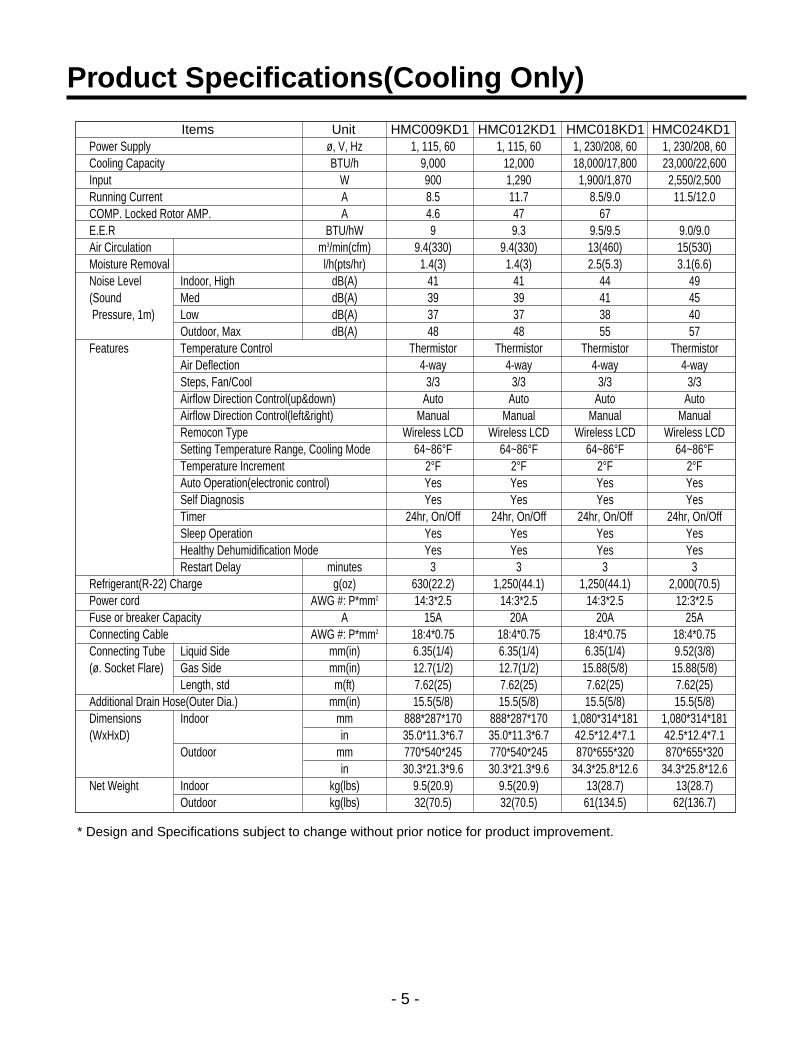
Product Specifications(Cooling Only)
Items Unit HMC009KD1 HMC012KD1 HMC018KD1 HMC024KD1Power Supply ø, V, HzCooling Capacity BTU/hInput WRunning Current ACOMP. Locked Rotor AMP. AE.E.R BTU/hWAir Circulation m3/min(cfm)Moisture Removal l/h(pts/hr)Noise Level Indoor, High dB(A)(Sound Med dB(A)Pressure, 1m) Low dB(A)
Outdoor, Max dB(A)Features Temperature Control
Air DeflectionSteps, Fan/CoolAirflow Direction Control(up&down)Airflow Direction Control(left&right)Remocon TypeSetting Temperature Range, Cooling ModeTemperature IncrementAuto Operation(electronic control)Self DiagnosisTimerSleep OperationHealthy Dehumidification ModeRestart Delay minutes
Refrigerant(R-22) Charge g(oz)Power cord AWG #: P*mm2
Fuse or breaker Capacity AConnecting Cable AWG #: P*mm2
Connecting Tube Liquid Side mm(in)(ø. Socket Flare) Gas Side mm(in)
Length, std m(ft)Additional Drain Hose(Outer Dia.) mm(in)Dimensions Indoor mm(WxHxD) in
Outdoor mmin
Net Weight Indoor kg(lbs)Outdoor kg(lbs)
1, 115, 60 1, 115, 60 1, 230/208, 60 1, 230/208, 609,000 12,000 18,000/17,800 23,000/22,600900 1,290 1,900/1,870 2,550/2,5008.5 11.7 8.5/9.0 11.5/12.04.6 47 679 9.3 9.5/9.5 9.0/9.0
9.4(330) 9.4(330) 13(460) 15(530)1.4(3) 1.4(3) 2.5(5.3) 3.1(6.6)
41 41 44 4939 39 41 4537 37 38 4048 48 55 57
Thermistor Thermistor Thermistor Thermistor4-way 4-way 4-way 4-way
3/3 3/3 3/3 3/3Auto Auto Auto Auto
Manual Manual Manual ManualWireless LCD Wireless LCD Wireless LCD Wireless LCD
64~86°F 64~86°F 64~86°F 64~86°F2°F 2°F 2°F 2°FYes Yes Yes YesYes Yes Yes Yes
24hr, On/Off 24hr, On/Off 24hr, On/Off 24hr, On/OffYes Yes Yes YesYes Yes Yes Yes
3 3 3 3630(22.2) 1,250(44.1) 1,250(44.1) 2,000(70.5)14:3*2.5 14:3*2.5 14:3*2.5 12:3*2.5
15A 20A 20A 25A18:4*0.75 18:4*0.75 18:4*0.75 18:4*0.756.35(1/4) 6.35(1/4) 6.35(1/4) 9.52(3/8)12.7(1/2) 12.7(1/2) 15.88(5/8) 15.88(5/8)7.62(25) 7.62(25) 7.62(25) 7.62(25)15.5(5/8) 15.5(5/8) 15.5(5/8) 15.5(5/8)
888*287*170 888*287*170 1,080*314*181 1,080*314*18135.0*11.3*6.7 35.0*11.3*6.7 42.5*12.4*7.1 42.5*12.4*7.1770*540*245 770*540*245 870*655*320 870*655*32030.3*21.3*9.6 30.3*21.3*9.6 34.3*25.8*12.6 34.3*25.8*12.6
9.5(20.9) 9.5(20.9) 13(28.7) 13(28.7)32(70.5) 32(70.5) 61(134.5) 62(136.7)
* Design and Specifications subject to change without prior notice for product improvement.

- 6 -
Product Specifications(Cooling & Heating)
Items Unit HMH009KD1 HMH012KD1 HMH018KD1 HMH024KD1Power Supply ø, V, Hz 1, 115, 60 1, 115, 60 1, 230/208, 60 1, 230/208, 60Cooling Capacity BTU/h 9,000 12,000 18,000/17,800 23,000/22,600Heating Capacity BTU/h 9,000 12,000 19,000/18,700 23,000/22,600Input Cooling W 900 1,290 1,900/1,870 2,550/2,500
Heating W 900 1,290 1,900/1,870 2,550/2,500Running Current Cooling A 8 11.7 8.5/9.0 11.5/12.0
Heating A 8 11.7 8.5/9.0 11.5/12.0COMP. Locked Cooling A 51 58 42 67Rotor AMP. Heating A 51 58 42 67E.E.R BTU/hW 9 9.3 9.5/9.5 9.0/9.0C.O.P 2.93 2.75 2.9/2.9 2.6/2.6Air Circulation m3/min(cfm) 7.1(250) 9.4(330) 13(460) 15(530)Moisture Removal l/h(pts/hr) 1.2(2.6) 1.4(3) 2.5(5) 3.1(6.6)Noise Level Indoor, High dB(A) 38 41 44 47(Sound Med dB(A) 36 39 41 44Pressure, 1m) Low dB(A) 35 37 38 40
Outdoor, Max dB(A) 48 48 55 58Features Temperature Control Thermistor Thermistor Thermistor Thermistor
Air Deflection 4-way 4-way 4-way 4-waySteps, Fan/Cool/Heat 3/3/3 3/3/3 3/3/3 3/3/3Airflow Direction Control(up&down) Auto Auto Auto AutoAirflow Direction Control(left&right) Manual Manual Manual ManualRemocon Type Wireless LCD Wireless LCD Wireless LCD Wireless LCDSetting Temperature Range, Cooling Mode 64~86°F 64~86°F 64~86°F 64~86°FHeating Mode 60~86°F 60~86°F 60~86°F 60~86°FTemperature Increment 2°F 2°F 2°F 2°FAuto Operation(electronic control) Yes Yes Yes YesSelf Diagnosis Yes Yes Yes YesTimer 24hr, On/Off 24hr, On/Off 24hr, On/Off 24hr, On/OffSleep Operation Yes Yes Yes YesHealthy Dehumidification Mode Yes Yes Yes YesRestart Delay minutes 3 3 3 3Defrost Control Yes Yes Yes YesHot Start Yes Yes Yes Yes
Refrigerant(R-22) Charge g(oz) 700(24.7) 840(29.6) 1350(47.6) 1900(67.0)Power cord AWG #: P*mm2 14:3*2.5 14:3*2.5 14:3*2.5 14:3*2.5Fuse or breaker Capacity A 20A 20A 20A 25AConnecting Cable AWG #: P*mm2 18:4*0.75 18:4*0.75 18:4*0.75 18:4*0.75Connecting Tube Liquid Side mm(in) 6.35(1/4) 6.35(1/4) 6.35(1/4) 9.52(3/8)(ø. Socket Flare) Gas Side mm(in) 12.7(1/2) 12.7(1/2) 15.88(5/8) 15.88(5/8)
Length, std m(ft) 7.62(25) 7.62(25) 7.62(25) 7.62(25)Additional Drain Hose(Outer Dia.) mm(in) 15.5(5/8) 15.5(5/8) 15.5(5/8) 15.5(5/8)Dimensions Indoor mm 802*262*165 888*287*170 1080*314*181 108*314*181(WxHxD) in 31.6*10.3*6.5 35.0*11.3*6.7 42.5*12.4*7.1 42.5*12.4*7.1
Outdoor mm 770*540*245 770*540*245 870*655*320 870*655*320in 30.3*21.3*9.6 30.3*21.3*9.6 34.3*25.8*12.6 34.3*25.8*12.6
Net Weight Indoor kg(lbs) 7(15.4) 9.5(20.9) 13(28.7) 13(28.7)Outdoor kg(lbs) 33(72.8) 33(72.8) 62(136.7) 63(138.9)
* Design and Specifications subject to change without prior notice for product improvement.

(1) Indoor Unit
- 7 -
Dimensions
D
W
H
Tubing hole cover
Tubing hole cover
Installation plate
MODEL9K 12K 18K, 24K
DIM
W mm(inch) 802(31.6") 888(35.0") 1,080(42.5")
H mm(inch) 262(10.3") 287(11.3") 314(12.4")
D mm(inch) 165(6.5") 170(6.7") 181(7.1")

- 8 -
(2) Outdoor Unit 1. 9K, 12K
W L2
L3
L1 D
H
L4
L5
Gas side(3-way valve)
Liquid side(2-way valve)
MODEL9K, 12K
DIM unit
W mm(inch) 770(30.3)
H mm(inch) 540(21.3)
D mm(inch) 245(9.6)
L1 mm(inch) 287(11.3)
L2 mm(inch) 64(2.5)
L3 mm(inch) 518(20.4)
L4 mm(inch) 10(0.4)
L5 mm(inch) 100(3.9)

- 9 -
W
L6 L5 L7 L8
D L1
L2
L9L1
0
L3L4
H
Gas side3-way valve
Liquid side3-way valve
2. 18K, 24K
MODEL18K, 24K
DIM
W mm(inch) 870(34.3)
H mm(inch) 655(25.8)
D mm(inch) 320(12.6)
L1 mm(inch) 370(14.6)
L2 mm(inch) 25(1.0)
L3 mm(inch) 630(24.8)
L4 mm(inch) 25(1.0)
L5 mm(inch) 546(21.5)
L6 mm(inch) 162(6.4)
L7 mm(inch) 162(6.4)
L8 mm(inch) 54(2.1)
L9 mm(inch) 74.5(2.9)
L10 mm(inch) 79(3.1)

- 10 -
For installation over rated, *a proper quantity of refrigerant should be added for each meter.
Ex) 18K: When installed at a distance of 15m, 295g of refrigerant should be added.(15-7.62) x 40g = 295g
INDOOR UNIT
HEATEXCHANGER(EVAPORATOR) HEAT
EXCHANGER(CONDENSER)
COMPRESSORGAS SIDE
CAPILLARY TUBELIQUID SIDE
OUTDOOR UNIT
• Cooling Only Models
MODEL
9K, 12K(Cooling Only)
18K(Cooling Only)
24K(Cooling Only)
Pipe size(Diameter:ø) Piping length Elevation
Gas Liquid Rated Max Rated Max
1/2" 1/4" 7.62m(25ft) 15m(50ft) 5m(16ft) 8m(26ft)
5/8" 1/4" 7.62m(25ft) 15m(50ft) 5m(16ft) 8m(26ft)
5/8" 3/8" 7.62m(25ft) 15m(50ft) 5m(16ft) 8m(26ft)
Refrigeration Cycle Diagram
a proper quantity of refrigerant
9K, 12K 20g
18K, 24K 40g

- 11 -
INDOOR UNIT
HEATEXCHANGER(EVAPORATOR)
HEATEXCHANGER(CONDENSER)
REVERSINGVALVE
COMPRESSOR COOLINGHEATING
GAS SIDE
CAPILLARY TUBE CHECK VALVELIQUID SIDE
OUTDOOR UNIT
• Cooling & Heating Models
MODEL
9K, 12K(Cooling & Heating)
18K(Cooling & Heating)
24K(Cooling & Heating)
Pipe size(Diameter:ø) Piping length Elevation
Gas Liquid Rated Max Rated Max
1/2" 1/4" 7.62m(25ft) 15m(50ft) 5m(16ft) 8m(26ft)
5/8" 1/4" 7.62m(25ft) 15m(50ft) 5m(16ft) 8m(26ft)
5/8" 3/8" 7.62m(25ft) 15m(50ft) 5m(16ft) 8m(26ft)
For installation over rated, *a proper quantity of refrigerant should be added for each meter.
Ex) 18K: When installed at a distance of 15m, 295g of refrigerant should be added.(15-7.62) x 40g = 295g
a proper quantity of refrigerant
9K, 12K 20g
18K, 24K 40g
- 12 -
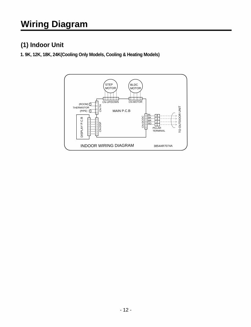
Wiring Diagram
(1) Indoor Unit1. 9K, 12K, 18K, 24K(Cooling Only Models, Cooling & Heating Models)
4321
BLDCMOTOR
STEPMOTOR
MAIN P.C.B
INDOOR WIRING DIAGRAM
TO
OU
TD
OO
R U
NIT
DIS
PLA
Y P
.C.B
(ROOM)
(PIPE)THERMISTOR
CN-UP/DOWN
3854AR7074A
CN-MOTOR
PILLARTERMINAL
CN
-DC
/DC
CN
-DIS
PC
N-T
H
BLBKBRRD

- 13 -
(2) Outdoor Unit
• Cooling Only Models1. 9K, 12K
3. 24K
2. 18K
BLBL
BK
BKFUSE3.15A
FUSE2.5A
ZNR
CN-DC/DC
RY-COMP
3 4
MAIN P.C.BYL
MOTOR
RD
BL
BR
BL
RD
BR
BL
TERMINALBLOCK
TO INDOOR UNIT
POWERINPUT
3854A30077ZOUTDOOR WIRING DIAGRAM
RD BR BK BL
G
HF
C
CA
PA
CIT
OR
CN
-TR
AN
S
TR
AN
SF
OR
ME
RT/B 1
CN-POWER
BRBR YL
O.L.PCOMP.SR C
(N) (L)
BLBL
BK
BKFUSE3.15A
FU
SE
2.5A
ZNR
CN-DC/DC
RY-COMP
3 4
MAIN P.C.B
BK T/B 1
MOTOR
YL
OR(BR)
BR
BR
BR
BR
RD
BL
BL
1 8
6420
BL
TERMINALBLOCK
TO INDOOR UNIT POWERINPUT
3854AR7077JOUTDOOR WIRING DIAGRAM
RD BR BK BL
G
H
F
C
CA
PA
CIT
OR
COMP.
R C
YLBR
BRO.L.P
BL
S
CN
-TR
AN
S
TR
AN
SF
OR
ME
R
CN-POWER
BLBL
BK
BKFUSE3.15A
FU
SE
2.5A
ZNR
CN-DC/DC
RY-COMP
3 4
MAIN P.C.B
BK T/B 1
MOTOR
YL
OR(BR)
BR
BR
BR
BR
RD
BL
BL
1 8
6420
BL
TERMINALBLOCK
TO INDOOR UNIT POWERINPUT
3854AR7077LOUTDOOR WIRING DIAGRAM
RD BR BK BL
G
H
F
C
CA
PA
CIT
OR
COMP.
R C
YLBR
BL
S
CN
-TR
AN
S
TR
AN
SF
OR
ME
R
CN-POWER

- 14 -
• Cooling & Heating Models1. 9K, 12K
2. 18K, 24K
4WAY-VALVE
BK RD RY-4WAY
BLBL
BK
BKFUSE3.15A
RY-FAN
RY-HEATERZNR
CN-DC/DC
RY-COMP
3 4
MAIN P.C.B
BK
YL
MOTOR
RD
BLRD
BR
BL
RDBR
O.L.P
BL
TERMINALBLOCK
TO INDOOR UNIT
POWERINPUT
3854A30077WOUTDOOR WIRING DIAGRAM
RD BR BK BL
WHWH
G
WH
WH
H
F
C
CA
PA
CIT
OR
COMP.
R C
YLBR
S
CRANKCASEHEATER
CN-4
WA
Y
CN
-TR
AN
S
TR
AN
SF
OR
ME
R
CN-F
AN
T/B 3
T/B 1T/B 2
T/B 4
CN-POWER
FUSE2.5A
(N) (L)
4WAY-VALVE
BK RDRY-4WAY
BLBL
BK
BKFUSE3.15A
FU
SE
2.5A
RY-FAN
RY-HEATERZNR
CN-DC/DC
RY-COMP
3 4
MAIN P.C.B
BKBK
MOTOR
YL
OR(BR) RD
BK
BRBR
BR
BL
RD
BL
BL
1 8
6420
BL
TERMINALBLOCK
TO INDOOR UNIT POWERINPUT
3854AR7077MOUTDOOR WIRING DIAGRAM
RD BR BK BL
WHWH
G
WH
WH
H
F
C
CA
PA
CIT
OR
COMP.
R C
YLBR
S
CRANK CASEHEATER
CN-4
WA
Y
CN
-TR
AN
S
TR
AN
SF
OR
ME
R
CN-F
AN
T/B 1
T/B 3T/B 4
T/B 2
CN-POWER

(1) The function of main control1. Time delay Safety Control
• 3min.; The compressor operation is delayed for 3 minutes to balance the pressure of cycle.(Protection of compressor)
• 5sec.; The indoor fan is delayed for 5 seconds, when operating initially, to prevent noises occurred by the verticallouver and wind.
• 2min.; The reversing valve is delayed for 2 minutes to prevent the refrigerant-gas for abnormal noise when theheating operation is OFF or switched to the other operation mode while compressor is off.While compressor is running, it takes 3~5 seconds to switch.
2. Chaos Swing Mode• By the Chaos Swing key input, the upper/lower vane automatically operates with the Chaos Swing or they are
fixed to the desired direction.• While in Chaos Swing mode, the angles of cooling and heating cycle operations are different.
- 15 -
Operation Details
INTAKE AIR TEMP.
SETTING TEMP. +1°F(Compressor ON)
SETTING TEMP. -1°F(Compressor OFF)
Settingfan speed
Settingfan speed
More than3 minutes
More than3 minutes
Settingfan speed
COMPRESSOR ON OFF ON OFF ON
INDOOR FAN SPEED Low Low
Protection of the indoor heat exchanger from frosting
• Compressor and outdoor fan stop when indoor pipe temperature is below 0°C(32°F) and restart at the pipetemperature is above 7°C(45°F).
3. Cooling Operation Mode
• When selecting the Cooling( ) Mode Operation, the unit will operate according to the setting by theremote control and the operation diagram is shown below.
CLOSED
OPEN
< Cooling Mode >
8°
CLOSED
OPEN
< Heating Mode >
8°

4. Auto Operation (Electronic control mode)• The operation procedure is shown below. (Cooling & Heating Model)
If initial mode is decided, that mode is continued without the room temperature changing.
Auto Operation for Cooling
- 16 -
Press Start/Stop Button
Select Auto Operation Mode
Check the Room temperature
Operation mode
Indoor fan speed are decided automatically by the unit electronic control.
Setting temperature
Intake-airtemperature
Operation Mode
Over below70°F 76°F
Soft Dry
below 70°F
Heating
Over 76°F
Cooling
~
INTAKE AIR TEMP.
SETTING TEMP. +1°F(Compressor OFF)
SETTING TEMP. -1°F(Compressor ON)
COMPRESSOR ON OFF ON OFF
INDOOR FAN SPEED The electronic control operation
Intake-air Temperature Setting Temperature
Over 78°F 77°F
Over 76°F~below 78°F Intake air -1°C
Over 72°F~below 76°F Intake air -0.5°C
Over 68°F~below 72°F Intake air temperature
below 64°F 64°F
Over 64°F~below 86°F Electronic control
below 64°F 64°F
over 86°F 86°F
Operation Condition
When Auto Operationinitial start
Controlled bythe electroniccontrol
In this mode,when pressingthe vertical airdirection controlbutton, verticallouver swings upand down automatically.
Fan Speed Air Direction Control
When pressing roomtemperature setting button during AutoOperation

Auto Operation for Dehumidification(only Heating Model)
• The Setting temperature will be same that of the auto operation for cooling.- Compressor ON temperature; Setting temperature +2°F- Compressor OFF temperature; Setting temperture -1°F
Auto Operation for Heating(only Heating Model)
- Compressor ON temperature; Setting temperature
- Compressor OFF temperature; Setting temperature +6°F
- 17 -
Intake-air temp. below 68°F Over 68°F~below 70°F over 86°F
Setting temp. 68°F Intake air temperature +1°F 86°F
Vertical louver auto operation : During Auto Operation, pressing the chaos swing button makes the horizon-tal louvers swing up and down automatically.If you want to stop auto-swing, press chaos swing button again.

5. Healthy Dehumidification• When the dehumidification operation input by the remote control is received, the intake air temperature is
detected and the setting temp is automatically set according to the intake air temperature.26°C ≤ Intake Air Temp 25°C24°C ≤ Intake Intake Air Temp<26°C Intake Air Temp-1°C18°C ≤ Intake Intake Air Temp<24°C Intake Air Temp-0.5°CIntake Air Temp<18°C 18°C
• While in compressor off, the indoor fan repeats low airflow speed and pause.• While the intake air temp is between compressor on temp. and compressor off temp., 10-min dehumidification
operation and 4-min compressor off repeat.Compressor ON Temp. Setting Temp+0.5°CCompressor OFF Temp. Setting Temp-0.5°C
• In 10-min dehumidification operation, the indoor fan operates with the low airflow speed.
- 18 -
- 19 -
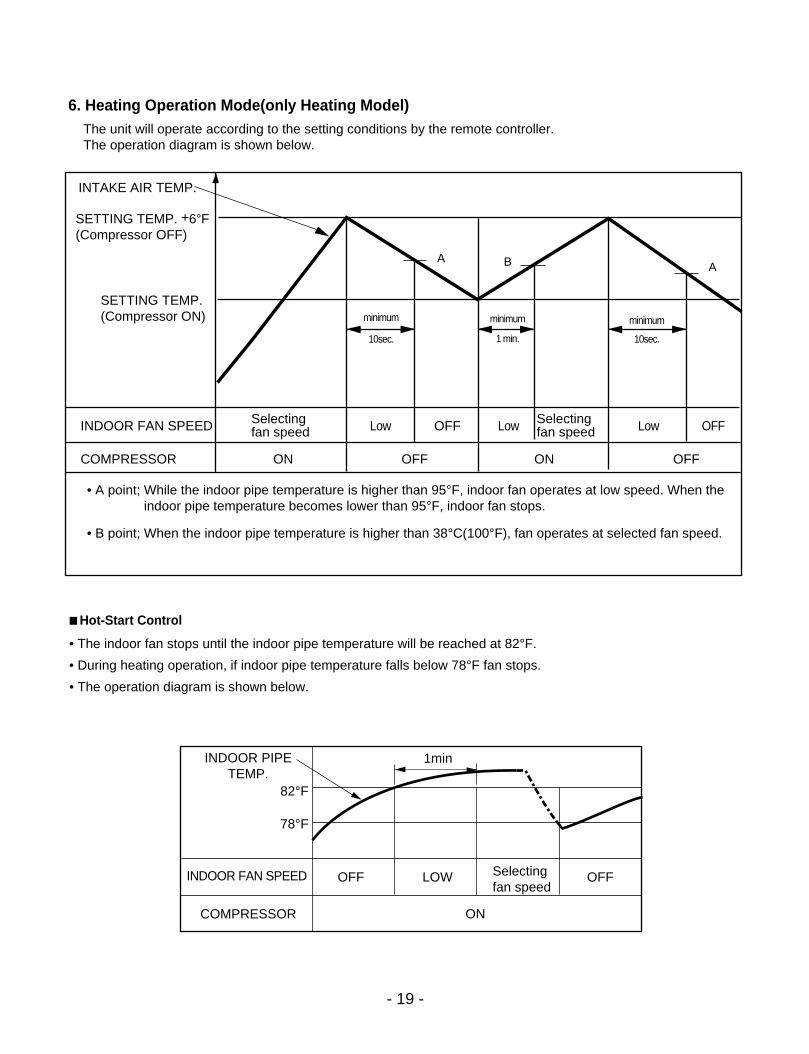
6. Heating Operation Mode(only Heating Model)The unit will operate according to the setting conditions by the remote controller.The operation diagram is shown below.
INTAKE AIR TEMP.
SETTING TEMP. +6°F(Compressor OFF)
SETTING TEMP.(Compressor ON)
Selectingfan speed
Selectingfan speed
A B A
minimum
10sec.
minimum
1 min.
minimum
10sec.
COMPRESSOR ON OFF ON OFF
• A point; While the indoor pipe temperature is higher than 95°F, indoor fan operates at low speed. When theindoor pipe temperature becomes lower than 95°F, indoor fan stops.
• B point; When the indoor pipe temperature is higher than 38°C(100°F), fan operates at selected fan speed.
INDOOR FAN SPEED Low OFF Low Low OFF
OFF OFFLOW
ON
Selecting fan speed
INDOOR PIPETEMP.
82°F
78°F
1min
INDOOR FAN SPEED
COMPRESSOR
Hot-Start Control
• The indoor fan stops until the indoor pipe temperature will be reached at 82°F.
• During heating operation, if indoor pipe temperature falls below 78°F fan stops.
• The operation diagram is shown below.

7. Cooling or Heating Mode with Sleep Mode Auto Control• When selecting the Cooling( ) or the Heating( ) combined with the Sleep Mode Auto Control( ), the
operation diagram is as following.
Cooling Mode with the Sleep Mode
• The setting temperature will be automatically raised by 2°F 30 minutes later and by 4°F 1 hour later.
• The operation will be stopped after 1, 2, 3, 4, 5, 6, 7 hours.
Heating Mode with the Sleep Mode(only Heating Model)
• The operation will be stopped after 1, 2, 3, 4, 5, 6, 7 hours.
- 20 -
INTAKE AIR TEMP.
SETTING TEMP. +1°F(Compressor ON)SETTING TEMP. -1°F(Compressor OFF)
30 minutes 30 minutes
More than3 minutes
2°F
2°F
More than3 minutes
COMPRESSOR ON OFF ON OFF ON
INDOOR FAN SPEED Low Low Low Low Low
SETTING TEMP. +6°F(Compressor OFF)
SETTING TEMP.(Compressor ON)
COMPRESSOR ON OFF ON OFF ON OFF
INDOOR FAN SPEED Med Low or OFF Med Low or OFF Med Low or OFF
INTAKE AIR TEMP.
More than3 minutes
More than3 minutes
More than3 minutes
- 21 -
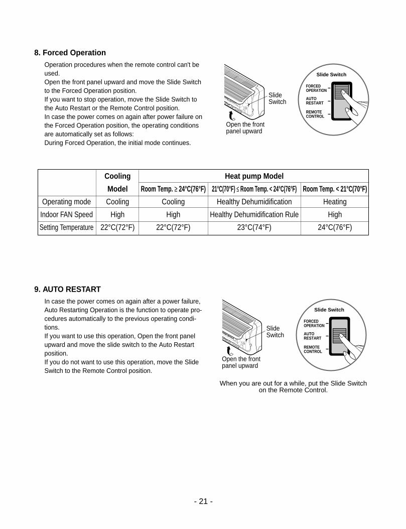
8. Forced OperationOperation procedures when the remote control can't beused.Open the front panel upward and move the Slide Switchto the Forced Operation position.If you want to stop operation, move the Slide Switch tothe Auto Restart or the Remote Control position. In case the power comes on again after power failure onthe Forced Operation position, the operating conditionsare automatically set as follows:During Forced Operation, the initial mode continues.
9. AUTO RESTARTIn case the power comes on again after a power failure,Auto Restarting Operation is the function to operate pro-cedures automatically to the previous operating condi-tions.If you want to use this operation, Open the front panelupward and move the slide switch to the Auto Restartposition.If you do not want to use this operation, move the SlideSwitch to the Remote Control position.
When you are out for a while, put the Slide Switchon the Remote Control.
Cooling Heat pump Model
Model Room Temp. ≥ 24°C(76°F) 21°C(70°F) ≤ Room Temp. < 24°C(76°F) Room Temp. < 21°C(70°F)
Operating mode Cooling Cooling Healthy Dehumidification Heating
Indoor FAN Speed High High Healthy Dehumidification Rule High
Setting Temperature 22°C(72°F) 22°C(72°F) 23°C(74°F) 24°C(76°F)
Open the frontpanel upward
SlideSwitch
Slide Switch
FORCEDOPERATION
AUTORESTART
REMOTECONTROL
Open the frontpanel upward
SlideSwitch
Slide Switch
FORCEDOPERATION
AUTORESTART
REMOTECONTROL

• Cooling, Soft Dry, Fan, Heating
• Sleep Mode
• Timer Mode
• Hot-start, Defrost
• Compressor ON
• BUZZER SOUND• Power Input or Reset : One short beep.
• When Operation Stop Button is pressed : One long beep.
• When Remote Controller Buttons except for Operation Stop are pressed : Two short beep.
- 22 -
Display Function
Self-diagnosis Function
Operation Indicator
Sleep timer Indicator
Timer Indicator
Defrost Indicator or Hot start Indicator
OUTDOOR
: Cooling & Heating Model only
: only Cooling Model
CODE NO. DIAGNOSIS Operation Indicator LED Blinks Unit Operation
① Once Still Operation
② Outdoor pipe thermistor Short/Open Twice Outdoor Unit Off
③ 5 times Stop
Indoor room temperature thermistor orpipe temperature thermistor Short/Open
Communication failure between indoor andoutdoor
• LED blinks as many times as code No. (0.5 second ON/0.5 second OFF) with 3 seconds interval.
• While the unit is off, no indication displays.
• If more than one code occurs simultaneously, bigger code No. is displayed.

- 23 -
Installation
IMPORTANT!Please read this instruction sheet completely before installing the product.This air conditioning system meets strict safety and operating standards. As the installer or service person, it is an important part ofyour job to install or service the system so it operates safely and efficiently.
CAUTION: Improper installation, adjustment, alteration, service or maintenance can void the warranty.The weight of the condensing unit requires caution and proper handling procedures when lifting or moving to avoidpersonal injury. Use care to avoid contact with sharp or pointed edges.
Safety Precautions• Always wear safety eye wear and work gloves when installing equipment.• Never assume electrical power is disconnected. Check with meter and equipment.• Keep hands out of fan areas when power is connected to equipment.• R-22 causes frostbite burns.• R-22 is toxic when burned.
NOTE TO INSTALLING DEALER: The Owners Instructions and Warranty are to be given to the owner or prominently displayednear the indoor Furnace/Air Handler Unit.
• Installation or repairs made by unqualified persons can result in hazards to you and others.Installation MUST conform with local building codes or, in the absence of local codes, with the National Electrical Code NFPA 70/ANSI C1-1993 or current edi-tion and Canadian Electrical Code Part1 CSA C.22.1.
• The information contained in the manual is intended for use by a qualified service technician familiar with safety procedures and equipped with the proper toolsand test instruments.
• Failure to carefully read and follow all instructions in this manual can result in equipment malfunction, property damage, personal injury and/or death.
WARNING
Special warningsWhen wiring:
Electrical shock can cause severe personal injury or death. Only a qualified, experienced electrician should attempt to wire this system.
• Do not supply power to the unit until all wiring and tubing are completed or reconnected and checked.• Highly dangerous electrical voltages are used in this system. Carefully refer to the wiring diagram and these instructions when wiring. Improper connectionsand inadequate grounding can cause accidental injury or death.
• Ground the unit following local electrical codes.• Connect all wiring tightly. Loose wiring may cause overheating at connection points and a possible fire hazard.
When transporting:
Be careful when picking up and moving the indoor and outdoor units. Get a partner to help, and bend your knees when lifting to reduce strain onyour back. Sharp edges or thin aluminum fins on the air conditioner can cut your finger.
When installing...
... in a wall: Make sure the wall is strong enough to hold the unit's weight.It may be necessary to construct a strong wood or metal frame to provide added support.
... in a room: Properly insulate any tubing run inside a room to prevent "sweating" that can cause dripping and water damage to wall and floors.
... in moist or uneven locatinons: Use a raised concrete pad or concrete blocks provide a solid, level foundation for the outdoor unit. This preventswater damage and abnormal vibration.
... in an area with high winds: Securely anchor the outdoor unit down with bolts and a metal frame. Provide a suitable air baffle.
... in a snowy area(for Heat Pump Model): Install the outdoor unit on a raised platform that is higher than drifting snow. Provide snow vents.When connecting refrigerant tubing
• Keep all tubing runs as short as possible.• Use the flare method for connecting tubing.• Check carefully for leaks before starting the test run.
When servicing
• Turn the power OFF at the main power box(mains) before opening the unit to check or repair electrical parts and wiring.• Keep your fingers and clothing away from any moving parts.
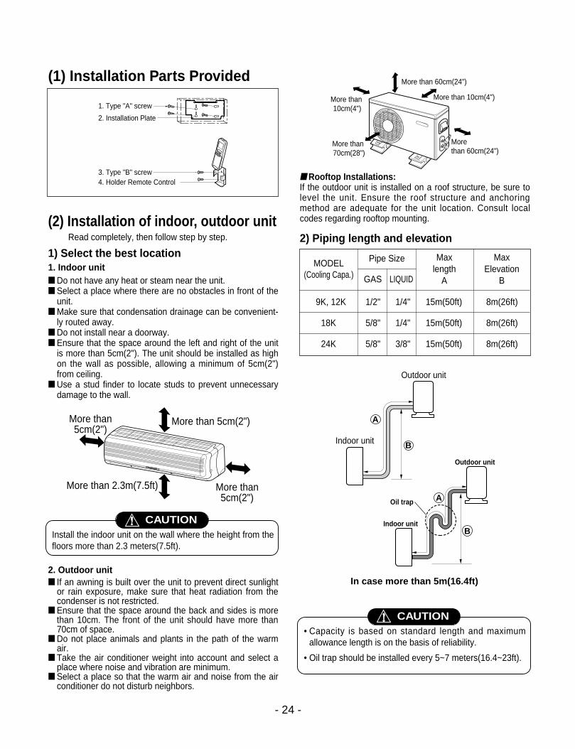
(1) Installation Parts Provided
(2) Installation of indoor, outdoor unitRead completely, then follow step by step.
1) Select the best location 1. Indoor unit Do not have any heat or steam near the unit. Select a place where there are no obstacles in front of the
unit. Make sure that condensation drainage can be convenient-
ly routed away. Do not install near a doorway. Ensure that the space around the left and right of the unit
is more than 5cm(2"). The unit should be installed as highon the wall as possible, allowing a minimum of 5cm(2")from ceiling.
Use a stud finder to locate studs to prevent unnecessarydamage to the wall.
2. Outdoor unit If an awning is built over the unit to prevent direct sunlight
or rain exposure, make sure that heat radiation from thecondenser is not restricted.
Ensure that the space around the back and sides is morethan 10cm. The front of the unit should have more than70cm of space.
Do not place animals and plants in the path of the warmair.
Take the air conditioner weight into account and select aplace where noise and vibration are minimum.
Select a place so that the warm air and noise from the airconditioner do not disturb neighbors.
Rooftop Installations:If the outdoor unit is installed on a roof structure, be sure tolevel the unit. Ensure the roof structure and anchoringmethod are adequate for the unit location. Consult localcodes regarding rooftop mounting.
2) Piping length and elevation
- 24 -
1. Type "A" screw
2. Installation Plate
3. Type "B" screw4. Holder Remote Control
More than 5cm(2")More than5cm(2")
More than 2.3m(7.5ft) More than5cm(2")
More than 10cm(4")
More than 10cm(4")
More than 60cm(24")
More than 60cm(24")
More than 70cm(28")
Install the indoor unit on the wall where the height from thefloors more than 2.3 meters(7.5ft).
CAUTION
MODEL(Cooling Capa.)
Pipe Size
GAS LIQUID
Max length
A
Max Elevation
B
9K, 12K 1/2" 1/4" 15m(50ft) 8m(26ft)
18K 5/8" 1/4" 15m(50ft) 8m(26ft)
24K 5/8" 3/8" 15m(50ft) 8m(26ft)
A
Outdoor unit
Indoor unit B
AOil trap
Outdoor unit
Indoor unitB
In case more than 5m(16.4ft)
• Capacity is based on standard length and maximumallowance length is on the basis of reliability.
• Oil trap should be installed every 5~7 meters(16.4~23ft).
CAUTION

3) How to fix installation plateThe wall you select should be strong and solid enough toprevent vibration
1. Mount the installation plate on the wall with fourtype A screws. If mounting the unit on a concretewall, use anchor bolts. Mount the installation plate horizontally by aligning the
centerline using a level.
2. Measure the wall and mark the centerline. It is alsoimportant to use caution concerning the location ofthe installation plate-routing of the wiring to poweroutlets is through the walls typically. Drilling thehole through the wall for piping connections mustbe done safely.
For right rear piping and left rear piping, draw a line in thedirection of the arrow marked "A". The meeting point of thetwo lines is the center of the hole.
• The position of the center of the hole.
4) Drill a hole in the wall
Drill the piping hole with a ø70mm (0.76") hole core drill.Drill the piping hole at either the right or the left with thehole slightly slanted to the outdoor side.
- 25 -
Hole center
Right rear pipingLeft rear piping
ø70mm(2.76")
ø70mm(2.76")
50mm(1.97")
20m
m(0
.79"
)
20m
m(0
.79"
)
80mm(3.15")
A,B
A,B,CC
D
D
A,B,DC
A
B,DC
ø70mm(2.76")
Left rear piping Right rear piping
Hole Center Installation plate
9K Btu
12K Btu
A,B
A,B,CC
D
D
A,B,DC
A
B,DC
ø70mm(2.76")
Left rear piping Right rear piping
Hole Center Installation plate
18, 24K Btu
5-7m
m
(0.2
~0.
3")
IndoorWALL
Outdoor
Installation Plate
Marking-off line
ThreadWeight
Type "A" screw
A
A
AA
Left holecore position Right holecore position

(3) Flaring work and connectionof piping
1) Flaring workMain cause for gas leakage is due to defect in flaringwork. Carry out correct flaring work in the following pro-cedure.
1. Cut the pipes and the cable. Use the piping kit accessory or the pipes purchased
locally. Measure the distance between the indoor and the out-
door unit. Cut the pipes a little longer than measured distance. Cut the cable 1.5m(4.9ft) longer than the pipe length.
2. Burrs removal Completely remove all burrs from the cut cross section
of pipe/tube. Put the end of the copper tube/pipe in a downward
direction as you remove burrs in order to avoid droppingburrs into the tubing.
3. Putting nut on Remove flare nuts attached to indoor and outdoor unit,
then put them on pipe/tube having completed burrremoval. (not possible to put them on after flaring work)
4. Flaring work Carry out flaring work using flaring tool as shown below.
Firmly hold copper pipe in a die in the dimension shown inthe table above.
5. Check Compare the flared work with figure below. If flare is noted to be defective, cut off the flared section
and do flaring work again.
- 26 -
Copperpipe 90° Slanted Uneven Rough Bar
Copper pipe
Clamp handleRed arrow mark
Cone
Yoke
Handle
Bar"A"
Inclined
Inside is shiny without scratchesSmooth all round
Even lengthall round
Surfacedamaged
Cracked Uneventhickness
= Improper flaring =
Pipe
Reamer
Point down
Flare nut
Copper tube
Outside diameter A
mm inch mm
ø6.35 1/4 0~0.5
ø9.52 3/8 0~0.5
ø12.7 1/2 0~0.5
ø15.88 5/8 0~1.0

2) Connection of piping --Indoor Preparing the indoor unit's piping and drain hose for
installation through the wall. Remove the plastic tubing retainer(see illustration
below) and pull the tubing and drain hose away fromchassis.
Replace the plastic tubing holder in the original posi-tion.
1. Route the indoor tubing and the drain hose in thedirection of rear left.
2. Insert the connecting cable into the indoor unitfrom the outdoor unit through the piping hole. Do not connect the cable to the indoor unit. Make a small loop with the cable for easy connection
later.
3. Tape the tubing, drain hose and the connectingcable. Be sure that the drain hose is located at thelowest side of the bundle. Locating at the upper sidecan cause drain pan to overflow inside the unit.
NOTE: If the drain hose is routed inside the room, insulatethe hose with an insulation material* so that dripping from"sweating"(condensation) will not damage furniture or floors.*Foamed polyethylene or equivalent is recommended.
4. Indoor unit installation Hook the indoor unit onto the upper portion of the instal-
lation plate.(Engage the two hooks of the rear top of theindoor unit with the upper edge of the installation plate.)Ensure that the hooks are properly seated on the instal-lation plate by moving it left and right.
Press the lower left and right sides of the unit against theinstallation plate until the hooks engage into theirslots(clicking sound).
5. Connecting the pipings to the indoor unit and drainhose to drain pipe. Align the center of the pipings and sufficiently tighten
the flare nut by hand.
- 27 -
To remove the holder, press the bottom of chassis near the holder upward and pull the tab out of its hole.
Tubing holder
Pull
Press
2
1
Connecting cable
Loop
Gas sidepipingLiquid sidepipingDrain hose
Drain hose
Connectingcable
Indoor unit tubing Flare nut Pipings
Drain hose
When install, make sure that theremaining parts must be removedclearly so as not to damage the pip-ing and drain hose, especially con-necting cable.
CAUTION
For left rear piping

Tighten the flare nut with a wrench.
When extending the drain hose at the indoor unit, installthe drain pipe.
6. Wrap the insulation material around the connectingportion.
Overlap the connection pipe insulation material and theindoor unit pipe insulation material. Bind them togetherwith vinyl tape so that there is no gap.
Wrap the area which accommodates the rear piping hous-ing section with vinyl tape.
Bundle the piping and drain hose together by wrappingthem with vinyl tape over the range within which they fitinto the rear piping housing section.
1. Route the indoor tubing and the drain hose to therequired piping hole position.
2. Insert the piping, drain hose and the connectingcable into the piping hole.
- 28 -
Torquewrench
Indoorunit tubing
Spanner (fixed)
Connectionpipe
Flare nut
Vinyl tape(narrow)
Connectionpipe
Connecting cable
Vinyl tape(wide)
Wrap with vinyl tape
Indoor unit pipe
Pipe
Wrap with vinyl tape
Drain hose
Pipe
Vinyl tape(wide)
Drain pipe
Connecting cable
Vinyl tape(narrow)Adhesive
Drain pipe
Indoor unitdrain hose
Plastic bandsInsulation material
Pipe Size[Torque]
GAS LIQUID
9K 1/2"[5.5kg.m] 1/4"[1.8kg.m]
12K 1/2"[5.5kg.m] 1/4"[1.8kg.m]
18K 5/8"[6.6kg.m] 1/4"[1.8kg.m]
24K 5/8"[6.6kg.m] 3/8"[4.2kg.m]
Capacity(Btu/h)
For right rear piping

3. Insert the connecting cable into the indoor unit. Don't connect the cable to the indoor unit. Make a small loop with the cable for easy connection
later.
4. Tape the drain hose and the connecting cable.
5. Indoor unit installation Hang the indoor unit from the hooks at the top of the
installation plate. Insert the spacer etc. between the indoor unit and the
installation plate and separate the bottom of the indoorunit from the wall.
6. Connecting the pipings to the indoor unit and thedrain hose to drain pipe. Align the center of the pipings and sufficiently tighten
the flare nut by hand.
Tighten the flare nut with a wrench.
When extending the drain hose at the indoor unit, installthe drain pipe.
7. Wrap the insulation material around the connectingportion. Overlap the connection pipe heat insulation and the
indoor unit pipe heat insulation material. Bind themtogether with vinyl tape so that there is no gap.
Wrap the area which accommodates the rear pipinghousing section with vinyl tape.
- 29 -
Vinyl tapeAdhesive
Drain hose
Indoor unit drain hose
(narrow)
Plastic bandsInsulation material
Vinyl tape(narrow)
Connectionpipe
Connectingcable
Indoor unit piping
Pipe
Vinyl tape(wide)
Wrap with vinyl tape
Installation plate
SpacerIndoor unit
8cm(3.15")
Indoor unit tubing Flare nut Pipings
Torquewrench
Indoorunit tubing
Spanner (fixed)
Connectionpipe
Flare nut
Pipe Size[Torque]
GAS LIQUID
9K 1/2"[5.5kg.m] 1/4"[1.8kg.m]
12K 1/2"[5.5kg.m] 1/4"[1.8kg.m]
18K 5/8"[6.6kg.m] 1/4"[1.8kg.m]
24K 5/8"[6.6kg.m] 3/8"[4.2kg.m]
Capacity(Btu/h)

Bundle the piping and drain hose together by wrappingthem with cloth tape over the range within which they fitinto the rear piping housing section.
8. Reroute the pipings and the drain hose across theback of the chassis.
9. Set the pipings and the drain hose to the back ofthe chassis with the tubing holder. Hook the edge of tubing holder to tap on chassis and
push the bottom of tubing holder to be engaged at thebottom of chassis.
10. Indoor unit installation Remove the spacer. Ensure that the hooks are properly seated on the instal-
lation plate by moving it left and right.
Press the lower left and right sides of the unit against theinstallation plate until the hooks engage into theirslots(clicking sound).
3) Connection of the pipes-Outdoor
1. Align the center of the pipings and sufficientlytighten the flare nut by hand
2. Finally, tighten the flare nut with torque wrenchuntil the wrench clicks. When tightening the flare nut with torque wrench,
ensure the direction for tightening follows the arrow onthe wrench.
- 30 -
Drain hoseVinyl tape(narrow)
Pipe
Wrap with vinyl tape(wide)
Outdoor unitOutdoor unit
Liquid side piping(Smaller diameter)
Gas sidepiping(Biggerdiameter)
Torque wrench
Torque wrench
Piping forpassage throughpiping hole
Tubing holder
Hook
Push2
1
Drain hose
Connectingcable
Pipe Size[Torque]
GAS LIQUID
9K 1/2"[5.5kg.m] 1/4"[1.8kg.m]
12K 1/2"[5.5kg.m] 1/4"[1.8kg.m]
18K 5/8"[6.6kg.m] 1/4"[1.8kg.m]
24K 5/8"[6.6kg.m] 3/8"[4.2kg.m]
Capacity(Btu/h)
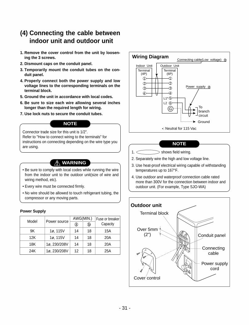
(4) Connecting the cable betweenindoor unit and outdoor unit
1. Remove the cover control from the unit by loosen-ing the 3 screws.
2. Dismount caps on the conduit panel.3. Temporarily mount the conduit tubes on the con-
duit panel.4. Properly connect both the power supply and low
voltage lines to the corresponding terminals on theterminal block.
5. Ground the unit in accordance with local codes.6. Be sure to size each wire allowing several inches
longer than the required length for wiring.7. Use lock nuts to secure the conduit tubes.
Power Supply
- 31 -
Connector trade size for this unit is 1/2".Refer to "How to connect wiring to the terminals" forinstructions on connecting depending on the wire type youare using.
NOTE
1. shows field wiring.
2. Separately wire the high and low voltage line.
3. Use heat-proof electrical wiring capable of withstandingtemperatures up to 167°F.
4. Use outdoor and waterproof connection cable ratedmore than 300V for the connection between indoor andoutdoor unit. (For example, Type SJO-WA)
NOTE
• Be sure to comply with local codes while running the wirefrom the indoor unit to the outdoor unit(size of wire andwiring method, etc).
• Every wire must be connected firmly.
• No wire should be allowed to touch refrigerant tubing, thecompressor or any moving parts.
WARNING
9K 1ø, 115V 14 18 15A
12K 1ø, 115V 14 18 20A
18K 1ø, 230/208V 14 18 20A
24K 1ø, 230/208V 12 18 25A
Model Power sourceFuse or breaker
CapacityAWG(MIN.)
1
Indoor Unit Outdoor Unit
2
3
4
1
2
3
4
5
6
G Tobranchcircuit
Ground
Power supply a
L1*
L2
Connecting cable(Low voltage)
*: Neutral for 115 Vac
b
Terminal(4P)
Terminal(6P)
Wiring Diagram
Outdoor unit
Terminal block
Over 5mm(2")
Cover control
Conduit panel
Connecting cable
Power supply cord

Connection method of the connecting cable(Example)(1) Dismount two-caps on the conduit panel.(2) Make a hole appropriate for the passage of connection
cable through on cap by tool. (for low voltage line)(3) Pass the connecting cable through the hole.(4) Properly connect the cable on the terminal block.(5) Fix the connection cable with clamp cord provided on
the unit not to have strain at the terminal when the con-nection cable is pulled outside up to a 35 poundweight.
(6) Wind the vinyl tape round the connecting cable forsealing between the surface of the connection cableand cap.
(7) Mount the taped part of cable on the cap.(8) Finally, mount the holed cap with the
wound cable on the conduit panel.
When connecting each power wire to the correspondingterminal, follow instructions "How to connect wiring to theterminals" and fasten the wire tightly with the fixing screwof the terminal plate.
How to connect wiring to the terminals For solid core wiring (or F-cable)
(1) Cut the wire end with a wire cutter of wire-cutting pli-ers, then strip the insulation to expose the solid wireabout 25mm(15/16")
(2) Using a screwdriver, remove the terminal screw(s)on the terminal plate.
(3) Using pliers, bend the solid wire to from a loop suit-able for the terminal screw.
(4) Shape the loop wire properly, place it on the terminalplater and tighten securely with the terminal screwusing a screwdriver.
For strand wiring(1) Cut the wire end with a wire cutter or wire-cutting pli-
ers, then strip the insulation to expose the strandwiring about 10mm(3/8").
(2) Using a screwdriver, remove the terminal screw(s)on the terminal plate.
(3) Using a round terminal fastener or pliers, securelyclamp each stripped wire end with a round terminal.
(4) Position the round terminal wire, and replace andtighten the terminal screw using a screwdriver.
- 32 -
Loose wiring may cause the terminal to overheat or resultin unit malfunction. A fire hazard may also exist.Therefore, be sure all wiring is tightly connected.
WARNING
G
Terminalblock
Cap(Remove)
Clamp cord
Lock nut
Conduit panel
Cap(Reuse)
Taping(for sealing)
Low voltage line(connecting cable)
Power supply line(1ø, 115V, 230/208V)
Hole(for low voltage line)
Loop
Roundterminal
Screw withspecial washer
Screw withspecial washer
Round terminal
Terminal plateWire
Wire
Round terminal
Insulation
Strip
25m
m(1
5/16
")St
rip 1
0mm
(3/8
")Solid wire
Strand wire
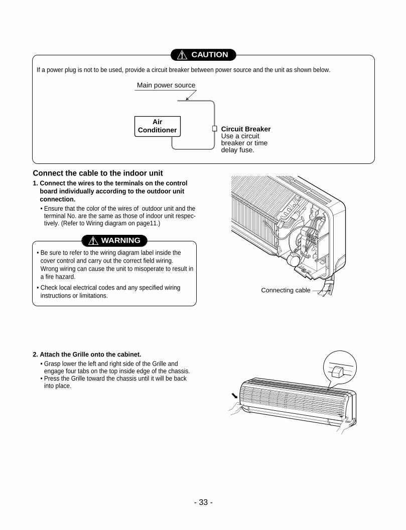
Connect the cable to the indoor unit1. Connect the wires to the terminals on the control
board individually according to the outdoor unitconnection.• Ensure that the color of the wires of outdoor unit and the
terminal No. are the same as those of indoor unit respec-tively. (Refer to Wiring diagram on page11.)
2. Attach the Grille onto the cabinet.• Grasp lower the left and right side of the Grille and
engage four tabs on the top inside edge of the chassis.• Press the Grille toward the chassis until it will be back
into place.
- 33 -
AirConditioner Circuit Breaker
Use a circuitbreaker or timedelay fuse.
Main power source
CAUTION
If a power plug is not to be used, provide a circuit breaker between power source and the unit as shown below.
• Be sure to refer to the wiring diagram label inside thecover control and carry out the correct field wiring.Wrong wiring can cause the unit to misoperate to result ina fire hazard.
• Check local electrical codes and any specified wiringinstructions or limitations.
WARNING
Connecting cable
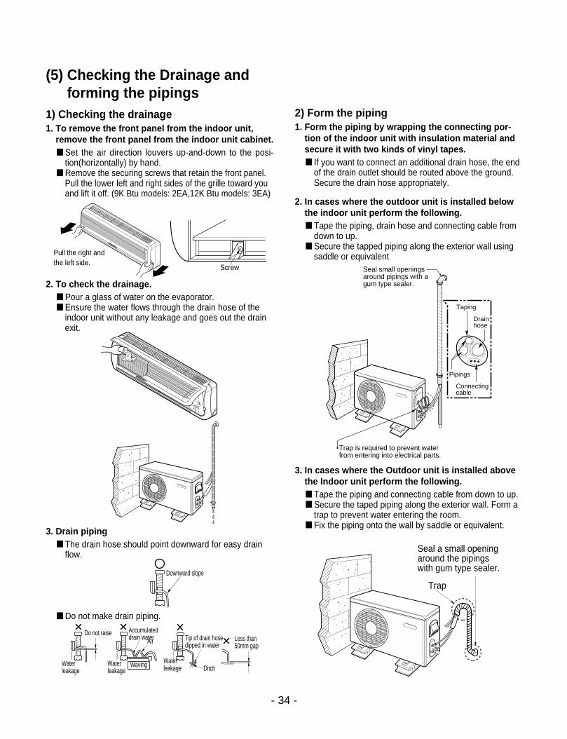
(5) Checking the Drainage andforming the pipings
1) Checking the drainage1. To remove the front panel from the indoor unit,
remove the front panel from the indoor unit cabinet. Set the air direction louvers up-and-down to the posi-
tion(horizontally) by hand. Remove the securing screws that retain the front panel.
Pull the lower left and right sides of the grille toward youand lift it off. (9K Btu models: 2EA,12K Btu models: 3EA)
2. To check the drainage. Pour a glass of water on the evaporator. Ensure the water flows through the drain hose of the
indoor unit without any leakage and goes out the drainexit.
3. Drain piping The drain hose should point downward for easy drain
flow.
Do not make drain piping.
2) Form the piping1. Form the piping by wrapping the connecting por-
tion of the indoor unit with insulation material andsecure it with two kinds of vinyl tapes. If you want to connect an additional drain hose, the end
of the drain outlet should be routed above the ground.Secure the drain hose appropriately.
2. In cases where the outdoor unit is installed belowthe indoor unit perform the following. Tape the piping, drain hose and connecting cable from
down to up. Secure the tapped piping along the exterior wall using
saddle or equivalent
3. In cases where the Outdoor unit is installed abovethe Indoor unit perform the following. Tape the piping and connecting cable from down to up. Secure the taped piping along the exterior wall. Form a
trap to prevent water entering the room. Fix the piping onto the wall by saddle or equivalent.
- 34 -
Pull the right andthe left side.
Screw
Trap is required to prevent waterfrom entering into electrical parts.
Seal small openingsaround pipings with agum type sealer.
Taping
Drainhose
Pipings
Connectingcable
Seal a small openingaround the pipingswith gum type sealer.
TrapDownward slope
Do not raise Accumulateddrain water Tip of drain hose
dipped in waterAir
WavingWaterleakage
Waterleakage Ditch
Less than 50mm gap
Waterleakage

(6) Air PurgingAir and moisture remaining in the refrigerant system haveundesirable effects as indicated below.• Pressure in the system rises.• Operating current rises.• Cooling(or heating) efficiency drops.• Moisture in the refrigerant circuit may freeze and block
capillary tubing.• Water may lead to corrossion of parts in the refrigeration
system.Therefore, the indoor unit and tubing between the indoor andoutdoor unit must be leak tested and evacuated to removeany noncondensables and moisture from the system.
Air Purging with a Vacuum Pump Preparation
Check that each tube(both liquid and gas side tubes)between the indoor and outdoor units has been properlyconnected and all wiring for the test run has been com-pleted. Remove the valve caps from both the gas and theliquid side service valves on the outdoor unit. Note thatboth liquid and gas side service valves on the outdoor unitare kept closed at this stage.
Leak test1. Connect the manifold valve(with pressure gauges)
and dry nitrogen gas cylinder to this service portwith charge hoses.CAUTION: Be sure to use a manifold valve for air purg-
ing. If it is not available, use a stop valve forthis purpose. The "Hi" knob of the manifoldvalve must always be kept close.
2. Pressurize the system to no more than 150 P.S.I.Gwith dry nitrogen gas and close the cylinder valvewhen the gauge reading reached 150 P.S.I.G. Next,test for leaks with liquid soap.CAUTION: To avoid nitrogen entering the refrigerant sys-
tem in a liquid state, the top of the cylindermust be higher than its bottom when you pres-surize the system. Usually, the cylinder isused in a vertial standing position.
3. Do a leak test of all joints of the tubing(both indoorand outdoor) and both gas and liquid side servicevalves. Bubbles indicate a leak. Be sure to wipe offthe soap with a clean cloth.
4. After the system is found to be free of leaks, relievethe nitrogen pressure by loosening the chargehose connnector at the nitrogen cylinder. When thesystem pressure is reduced to normal, disconnectthe hose from the cylinder.
- 35 -
Charge hose
Nitrogen gascylinder(in verticalstanding position)
Indoor unit
Outdoor unit
Lo Hi
Manifold valve
Pressure gauge

Evacuation1. Connect the charge hose end described in the pre-
ceding steps to the vacuum pump to evacuate thetubing and indoor unit.Confirm the "Lo" knob of the manifold valve isopen. Then, run the vacuum pump.The operation time for evacuation varied with thetubing length and capacity of the pump. The follow-ing table shows the amount of time for evacuation.Allow the pump to operate until the system hasbeen evacuated down to 300 microns. Allow thepump to continue running for an additional 15 min-utes. Turn off the pump and leave the connectionssecured to the two service valves. After 5 minutes,if the system fails to hold 500 microns or less,check all connections for tight fit and repeat theevacuation procedure.
2. When the desired vacuum is reached, close the"Lo" knob of the manifold valve and stop the vacu-um pump.
Finishing the job1. With a service valve wrench, turn the valve stem of
liquid side valve counter-clockwise to fully openthe valve.
2. Turn the valve stem of gas side valve counter-clockwise to fully open the valve.
3. Loosen the charge hose connected to the gas sideservice port slightly to release the pressure, thenremove the hose.
4. Replace the flare nut and its bonnet on the gas sideservice port and fasten the flare nut securely withan adjustable wrench. This process is very impor-tant to prevent gas leakage from the system.
5. Replace the vlave caps at both gas and liquid sideservice valves and fasten them securely tight.This complete air purging with a vacuum pump. The airconditoner is now ready to test run.
- 36 -
Indoor unit
Outdoor unit
Lo Hi
Manifold valve
Vacuum pump
Pressure gauge
Open Close
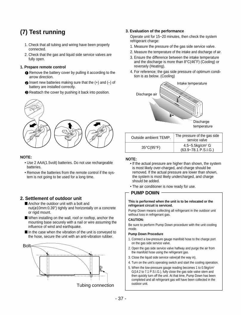
(7) Test running
1. Check that all tubing and wiring have been properlyconnected.
2. Check that the gas and liquid side service valves arefully open.
1. Prepare remote controlRemove the battery cover by pulling it according to thearrow direction.Insert new batteries making sure that the (+) and (–) ofbattery are installed correctly.Reattach the cover by pushing it back into position.
NOTE:• Use 2 AAA(1.5volt) batteries. Do not use rechargeable
batteries.• Remove the batteries from the remote control if the sys-
tem is not going to be used for a long time.
2. Settlement of outdoor unit Anchor the outdoor unit with a bolt and
nut(ø10mm:0.39") tightly and horizontally on a concreteor rigid mount.
When installing on the wall, roof or rooftop, anchor themounting base securely with a nail or wire assuming theinfluence of wind and earthquake.
In the case when the vibration of the unit is conveyed tothe hose, secure the unit with an anti-vibration rubber.
3. Evaluation of the performanceOperate unit for 15~20 minutes, then check the systemrefrigerant charge:1. Measure the pressure of the gas side service valve.2. Measure the temperature of the intake and discharge of air.3. Ensure the difference between the intake temperature
and the discharge is more than 8°C(46˚F) (Cooling) orreversely (Heating).
4. For reference; the gas side pressure of optimum condi-tion is as below. (Cooling)
NOTE: • If the actual pressure are higher than shown, the system
is most likely over-charged, and charge should beremoved. If the actual pressure are lower than shown,the system is most likely undercharged, and chargeshould be added.
• The air conditioner is now ready for use.
- 37 -
This is performed when the unit is to be relocated or therefrigerant circuit is serviced.Pump Down means collecting all refrigerant in the outdoor unitwithout loss in refrigerant gas.
CAUTION:Be sure to perform Pump Down procedure with the unit coolingmode.
Pump Down Procedure1. Connect a low-pressure gauge manifold hose to the charge port
on the gas side service valve.
2. Open the gas side service valve halfway and purge the air fromthe manifold hose using the refrigerant gas.
3. Close the liquid side service valve(all the way in).
4. Turn on the unit's operating switch and start the cooling operation.
5. When the low-pressure gauge reading becomes 1 to 0.5kg/cm2
G(14.2 to 7.1 P.S.I.G.), fully close the gas side valve stem andthen quickly turn off the unit. At that time, Pump Down has beencompleted and all refrigerant gas will have been collected in theoutdoor unit.
PUMP DOWN
Discharge temperature
Discharge air
Intake temperature
Bolt
Tubing connection
Outside ambient TEMP. The pressure of the gas side service valve
35°C(95°F) 4.5~5.5kg/cm2 G(63.9~78.1 P.S.I.G.)

- 38 -
Operation
(1) Name and Function-Remote Control (Cooling Models)
Signal transmitter.
Transmits the signalsto the room air conditioner.
Remote Controller
ON OFF
°C / °F
SET CANCEL
Signal transmitter
4
5
6
7
9
1
2
3
8
ON/OFF TIMER BUTTONSUsed to set the time of starting and stopping operation.
TIME SETTING BUTTONSUsed to adjust the time.
TIMER SET/CANCEL BUTTONSUsed to set the timer when the desired time is obtainedand to cancel the Timer operation.
SLEEP MODE AUTO BUTTONUsed to set Sleep Mode Auto operation.
AIR CIRCULATION BUTTONUsed to circulate the room air without cooling or heating(turns indoor fan on/off).
ROOM TEMPERATURE CHECKING BUTTONUsed to check the room temperature.
°C / °F SELECTING BUTTONChoose temperature unit °C or °F alternatively.
HORIZONTAL AIRFLOW DIRECTION CONTROLBUTTON (NOT ON ALL MODELS)Used to set the desired horizontal airflow direction.
RESET BUTTONUsed prior to resetting time or after replacing batteries.
1
2
3
4
5
6
7
8
9

- 39 -
(2) Name and Function-Remote Control (Heat Pump Models)
Signal transmitter.
Transmits the signalsto the room air conditioner.
Remote Controller
ON OFF
SET CANCEL
°C / °F
Signal transmitter
4
5
6
7
9
8
1
2
3
ON/OFF TIMER BUTTONSUsed to set the time of starting and stopping operation.
TIME SETTING BUTTONSUsed to adjust the time.
TIMER SET/CANCEL BUTTONSUsed to set the timer when the desired time is obtainedand to cancel the Timer operation.
SLEEP MODE AUTO BUTTONUsed to set Sleep Mode Auto operation.
AIR CIRCULATION BUTTONUsed to circulate the room air without cooling or heating(turns indoor fan on/off).
ROOM TEMPERATURE CHECKING BUTTONUsed to check the room temperature.
°C / °F SELECTING BUTTONChoose temperature unit °C or °F alternatively.
HORIZONTAL AIRFLOW DIRECTION CONTROLBUTTON (NOT ON ALL MODELS)Used to set the desired horizontal airflow direction.
RESET BUTTONUsed prior to resetting time or after replacing batteries.
1
2
3
4
5
6
7
8
9

- 40 -
Disassembly of the parts (Indoor unit)
Warning :Disconnect the unit from power supply before makingany checks.Be sure the power switch is set to “OFF”.
To remove the Grille from the Chassis. • Set the up-and-down air discharge louver to open
position (horizontally) by finger pressure.• Remove the securing screws
(9K Btu models: 2EA).• To remove the Grille, pull the lower left and right
side of the grille toward you (slightly tilted) and lift itstraight upward.
1. To remove the sensor, housing connect, earthconductor & step motor conductor with sensorholder, Motor, Evaporator & P.C.B.
PowerConductor
Step MotorConductor
EarthConductor
MotorConductor
SensorConductor
(1) 9K, 12K Models(Cooling Only, Cooling & Heating)

- 41 -
2. To remove the Control Box.• Remove 2 securing screws. • Pull the control box out from the chassis careful-
ly.
3. To remove the Discharge Grille.• Unhook the discharge grille and pull the dis-
charge grille out from the chassis carefully.
4. To remove the Evaporator. • Remove 3 screws securing the evaporator(at the
left 2EA in the Eva Holder, at the right 1EA).

- 42 -
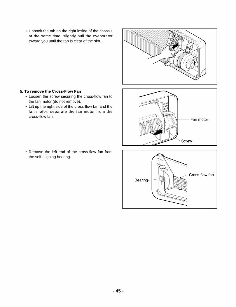
• Unhook the tab on the right inside of the chassisat the same time, slightly pull the evaporatortoward you until the tab is clear of the slot.
5. To remove the Cross-Flow Fan• Loosen the screw securing the cross-flow fan to
the fan motor (do not remove).• Lift up the right side of the cross-flow fan and the
fan motor, separate the fan motor from thecross-flow fan.
• Remove the left end of the cross-flow fan fromthe self-aligning bearing.

- 43 -
Warning :Disconnect the unit from power supply before makingany checks.Be sure the power switch is set to “OFF”.
To remove the Grille from the Chassis. • Set the up-and-down air discharge louver to open
position (horizontally) by finger pressure.• Remove the securing screws• To remove the Grille, pull the lower left and right
side of the grille toward you (slightly tilted) and lift itstraight upward.
1. To remove the sensor, housing connect, earthconductor & step motor conductor with sensorholder, Motor, Evaporator & P.C.B.
Screw(3EA)
MotorConductor
Step MotorConductor
EarthConductor
PowerConductor
SensorConductor
(2) 18K, 24K, Models Cooling Only, Cooling & Heating)

2. To remove the Control Box.• Remove 2 securing screws. • Pull the control box out from the chassis carefully.
3. To remove the Discharge Grille.• Remove the securing screw. • Pressing the right side of the discharge grille
downward slightly, unhook the discharge grille.• Pull the discharge grille out from the chassis
carefully.
4. To remove the Evaporator. • Remove 3 screws securing the evaporator(at the
left 1EA, at the right 2EA).
- 44 -
- 45 -
• Unhook the tab on the right inside of the chassisat the same time, slightly pull the evaporatortoward you until the tab is clear of the slot.
5. To remove the Cross-Flow Fan• Loosen the screw securing the cross-flow fan to
the fan motor (do not remove).• Lift up the right side of the cross-flow fan and the
fan motor, separate the fan motor from thecross-flow fan.
• Remove the left end of the cross-flow fan fromthe self-aligning bearing.

1. Trouble analysis1. Check temperature difference between intake and discharge air and operating current.
Temp. Difference
Operating Current
Temp. difference :approx. 0°FCurrent :less than 80% of
rated current
Temp. difference :approx. 8°C(14°F)Current :less than 80% of
rated current
Temp. difference :less than 8°C(14°F)Current :less than 80% of
rated current
Temp. difference :over 8°C(14°F)
All amount of refrigerant leaked out.Check refrigeration cycle.
Refrigerant leakage Clog of refrigeration cycleDefective compressor
Excessive amount of refrigerant
Normal
Notice:Temperature difference between intake and discharge air depends on room air humidity. When the room airhumidity is relatively higher, temperature difference is smaller. When the room air humidity is relatively lower temperature difference is larger.
2. Check temperature and pressure of refrigeration cycle.
Notice:1. The suction pressure is usually 4.5~5.0 kg/cm2G at normal condition.2. The temperature can be measured by attaching the thermometer to the low pressure tubing and wrap it with
putty.
- 46 -
Cycle Troubleshooting Guide
Suction pressure(Compared with the
normal value)
Temperature(Compared with the
normal value)Cause of Trouble Description
Higher
HighDefective compressorDefective 4-way reversing valve
Excessive amount of refrigerantHigh pressure does not quicklyrise at the beginning of operation.
Current is low.
Normal
Lower HigherInsufficient amount of refrigerant(Leakage) Clogging
Current is low.
Current is low.
- 47 -- 47 -
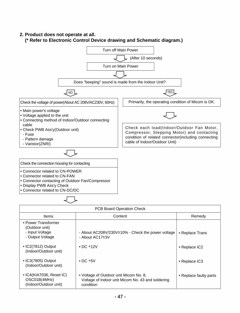
2. Product does not operate at all.(* Refer to Electronic Control Device drawing and Schematic diagram.)
Turn off Main Power
Turn on Main Power
Does "beeping" sound is made from the Indoor Unit?
Primarily, the operating condition of Micom is OK.Check the voltage of power(About AC 208V/AC230V, 60Hz)
• Main power's voltage• Voltage applied to the unit• Connecting method of Indoor/Outdoor connecting
cable• Check PWB Ass'y(Outdoor unit)
- Fuse- Pattern damage- Varistor(ZNRI)
Check the connection housing for contacting
• Connector related to CN-POWER• Connector related to CN-FAN• Connector contacting of Outdoor Fan/Compressor• Display PWB Ass'y Check• Connector related to CN-DC/DC
Check each load(Indoor/Outdoor Fan Motor,Compressor, Stepping Motor) and contacting condition of related connector(including connectingcable of Indoor/Outdoor Unit)
PCB Board Operation Check
Items
• Power Transformer(Outdoor unit)- Input Voltage- Output Voltage
• IC2(7812) Output(Indoor/Outdoor unit)
• IC3(7805) Output(Indoor/Outdoor unit)
• IC4(KIA7036, Reset IC)OSC01B(4MHz)(Indoor/Outdoor unit)
• Replace Trans
• Replace IC2
• Replace IC3
• Replace faulty parts
- About AC208V/230V±10% - Check the power voltage- About AC17±3V
• DC +12V
• DC +5V
• Voltage of Outdoor unit Micom No. 8, Voltage of Indoor unit Micom No. 43 and solderingcondition
Content Remedy
NO YES
(After 10 seconds)
- 48 -
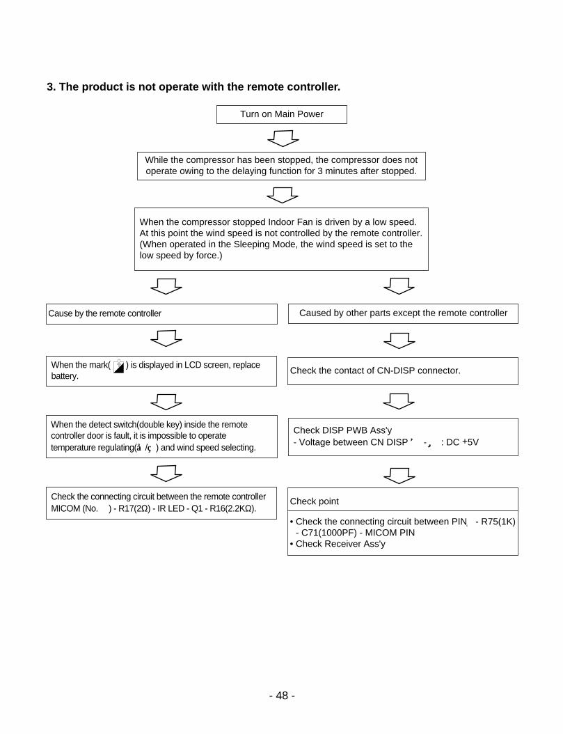
3. The product is not operate with the remote controller.
Turn on Main Power
While the compressor has been stopped, the compressor does notoperate owing to the delaying function for 3 minutes after stopped.
Caused by other parts except the remote controllerCause by the remote controller
When the mark( ) is displayed in LCD screen, replacebattery.
Check the contact of CN-DISP connector.
When the compressor stopped Indoor Fan is driven by a low speed.At this point the wind speed is not controlled by the remote controller.(When operated in the Sleeping Mode, the wind speed is set to thelow speed by force.)
Check DISP PWB Ass'y- Voltage between CN DISP ① - ⑦ : DC +5V
When the detect switch(double key) inside the remote controller door is fault, it is impossible to operate temperature regulating(/) and wind speed selecting.
Check the connecting circuit between the remote controllerMICOM (No. (30)) - R17(2Ω) - IR LED - Q1 - R16(2.2KΩ).
Check point
• Check the connecting circuit between PIN②- R75(1K)- C71(1000PF) - MICOM PIN
• Check Receiver Ass'y

- 49 -
4. Compressor/Outdoor Fan are unable to drive.
Turn on Main Power
Operate "Cooling Mode( )" by setting the desired temperature of theremote controller is less than one of the indoor temperature by 2°F at least.
When in Fan Mode, Compressor/Outdoor Fan is stopped.
Check the sensor for indoor temperature is attached as close as to beeffected by the temperature of Heat Exchanger(EVA).
When the sensor circuit for indoor temperature and connector are in badconnection or are not engaged, Compressor/Outdoor Fan is stopped.
• Check the related circuit of R02(12.1K), R04(6.2K), Micom (No.27)(Indoor unit).
• Check the indoor temperature sensor is disconnected or not(About 10kΩ / at 25°C).
When the temperature around Outdoor PWB Ass'y is above 163°F thecompressor is stop and only Outdoor Fan is operating.
Turn off Main Power
• Check the electrical wiring diagram of outdoor side.• Check the abnormal condition for the component of Compressor/Outdoor
Fan Motor.
Check Relay(RY - COMP) for driving compressor.
• When the power(About AC200V) is applied to the connecting wire termi-nal support transferred to compressor, PWB Ass'y is normal.
• Check the circuit related to the relay(Outdoor unit).Check point COMP ON COMP OFF
Between Micom(No.DC5V DC0V
15) and GNDBetween IC8(No. 16) Below DC 1V
About DC12Vand GND IC0M(No.16) (app)

- 50 -
5. When Indoor Fan does not operate.
Check connecting condition of the CN-MOTOR CON-NECTOR
Does the voltage of terminal of CN-DC/DC CONNECTOR inIndoor unit corresponds to the values in the table of page 51?
Do the voltage of terminal ofCN-DC/DC CONNECTOR inOutdoor unit corresponds to thevalues in the table of page 51?
Check the patterns and theconditions of outdoor unitPWB Assy's.
Check the connecting condi-tion and disconnection ofconnecting wires betweenIndoor and Outdoor unit.
Check the pattern and thecondition of Indoor unit PWBAss'y.
Check the interference of Indoor Fan.
Does the voltage of each terminals of CN-MOTOR CONNECTOR inIndoor unit corresponds to values in the Table of page 51?
Check the motor of Indoor Fan
※ Indoor Fan may be stopped in the Soft Dry Mode(change to the Cooling Operation Mode).
※ Indoor Fan is to be stopped when Indoor pipe(coil) termperature is lower than 79°F.
(At that times, Defrost indicator is turned on)
NO YES

- 51 -
• Confirm that the Vertical Louver is normally geared with the shaft ofStepping Motor.
• If the regular torque is detected when rotating the Vertical Louver withhands ⇒ Normal
• Check the connecting condition of CN-UP/DOWN Connector• Check the soldering condition(on PWB) of CN-UP/DOWN Connector
Check the operating circuit of the Vertical Louver
• Confirm that there is DC +12V between pin②(RED) of CN-UP/DOWN andGND.
• Confirm that there is a soldering short at following terminals.- Between 60 , 61 , 62 and 63 of MICOM- Between 3 , 4 , 5 and 6 of IC01M- Between 11 , 12 , 13 and 14 of IC01M- Between 1 , 2 , 3 , 4 and 5 of CN-UP/DOWN
If there are no problems after above checks
• Confirm the assembly conditions that are catching and interfering parts inthe rotation radial of the Vertical Louver
6. When Vertical Louver does not operate.

- 52 -
• The operation indicator of Indoor unit blinks five times.• The red indicator of Outdoor unit blinks five times.
Check the connecting wires between Indoor and Outdoor unit for the connecting error and the contacting condition.
Check the installation condition of outdoor unit.
Check for the communication error and the operating condition of productafter also operating with the remote controller, then taking above 2 minutes.
Apply the power again after about 10 seconds by the power of Outdoor unitis off.
Check for the communication error and the operating condition of productafter also operating with the remote controller, then taking above 2 minutes.
Check the PWB assembly of Indoor and Outdoor unit.
Caution: If the connecting wires of Indoor and Outdoor unit are not connected within 2 minutes after the powerof Outdoor unit is applied, a communication error will occur. Therefore, the power should be appliedafter connecting them.
7. When a comunication error occurs.
- 53 -
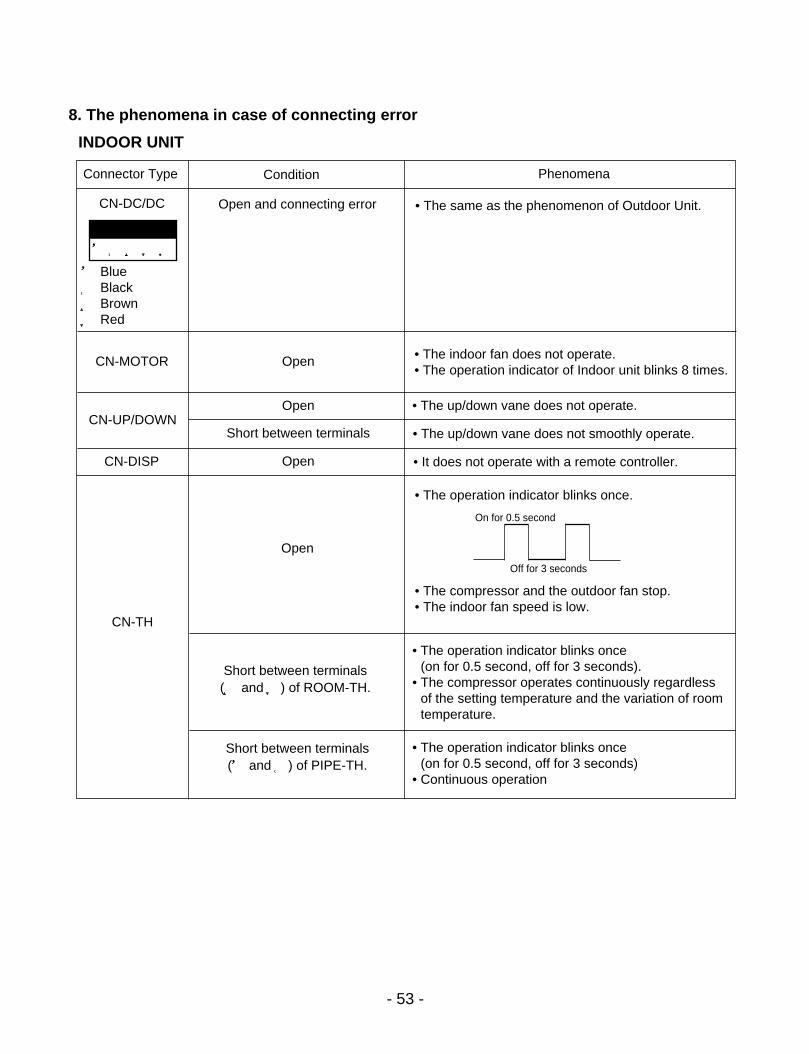
8. The phenomena in case of connecting error
INDOOR UNIT
Connector Type Condition
Open and connecting error
Open
Open
Open
Open
Short between terminals(③ and ④) of ROOM-TH.
Short between terminals(① and ②) of PIPE-TH.
Short between terminals
• The same as the phenomenon of Outdoor Unit.
• The up/down vane does not operate.
• The up/down vane does not smoothly operate.
• It does not operate with a remote controller.
• The operation indicator blinks once(on for 0.5 second, off for 3 seconds).
• The compressor operates continuously regardlessof the setting temperature and the variation of roomtemperature.
• The operation indicator blinks once(on for 0.5 second, off for 3 seconds)
• Continuous operation
• The operation indicator blinks once.
• The compressor and the outdoor fan stop.• The indoor fan speed is low.
• The indoor fan does not operate.• The operation indicator of Indoor unit blinks 8 times.
CN-DC/DC
CN-MOTOR
CN-UP/DOWN
CN-DISP
CN-TH
① Blue② Black③ Brown④ Red
Phenomena
①②③④⑤
On for 0.5 second
Off for 3 seconds
- 54 -
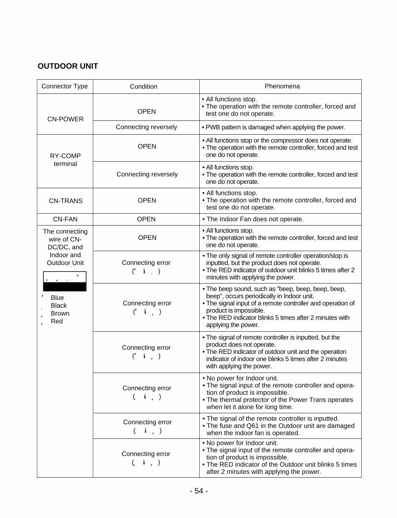
OUTDOOR UNIT
Connector Type Condition
OPEN
• PWB pattern is damaged when applying the power.Connecting reversely
Connecting reversely
OPEN
OPEN
OPEN
OPEN
Connecting error(① ↔②)
Connecting error(① ↔③)
Connecting error(① ↔④)
Connecting error(② ↔③)
Connecting error(② ↔④)
Connecting error(③ ↔④)
• All functions stop.• The operation with the remote controller, forced and
test one do not operate.
• All functions stop.• The operation with the remote controller, forced and
test one do not operate.
• The Indoor Fan does not operate.
• The signal of remote controller is inputted, but the product does not operate.
• The RED indicator of outdoor unit and the operation indicator of indoor one blinks 5 times after 2 minuteswith applying the power.
• No power for Indoor unit.• The signal input of the remote controller and opera-
tion of product is impossible.• The thermal protector of the Power Trans operates
when let it alone for long time.
• The signal of the remote controller is inputted.• The fuse and Q61 in the Outdoor unit are damaged
when the indoor fan is operated.
• No power for Indoor unit.• The signal input of the remote controller and opera-
tion of product is impossible.• The RED indicator of the Outdoor unit blinks 5 times
after 2 minutes with applying the power.
• All functions stop.• The operation with the remote controller, forced and test
one do not operate.
• The only signal of remote controller operation/stop isinputted, but the product does not operate.
• The RED indicator of outdoor unit blinks 5 times after 2minutes with applying the power.
• The beep sound, such as "beep, beep, beep, beep,beep", occurs periodically in Indoor unit.
• The signal input of a remote controller and operation ofproduct is impossible.
• The RED indicator blinks 5 times after 2 minutes withapplying the power.
• All functions stop or the compressor does not operate.• The operation with the remote controller, forced and test
one do not operate.
• All functions stop.• The operation with the remote controller, forced and test
one do not operate.
CN-POWER
RY-COMPterminal
CN-TRANS
CN-FAN
The connectingwire of CN-DC/DC, andIndoor and
Outdoor Unit
④ ③ ② ①
① Blue② Black③ Brown④ Red
Phenomena

9. Voltage of Connectors according to Indoor Fan Speed
- 55 -
1234
43211
1
4 31
23
45
23
45
62
IND
OO
RFA
NM
OTO
R
IND
OO
R P
WB
ASSY
Con
nect
ing
wire
sbe
twee
n In
door
and
Out
door
Indo
orC
onne
ctin
g Te
rmin
alO
utdo
orC
onne
ctin
g Te
rmin
al
Inpu
t Pow
er
POW
ERTR
ANS
CN
-PO
WER
CN-MOTOR
CN
-TR
ANS
CN
-DC
/DC
CN
-DC
/DC
RY-
CO
MP
BK
BLBK
BRR
D
BKBL
BL BK BR RD
+-
S-H
iH
iM
edLo
wO
ffS
-Hi
Hi
Med
Low
Off
S-H
iH
iM
edLo
wO
ffS
-Hi
Hi
Med
Low
Off
12
28.6
25.6
22.2
20.0
0.0
35.7
30.7
25.1
21.2
0.0
32.0
27.8
24.1
21.2
0.0
35.7
33.3
29.4
24.2
0.0
32
5.0
5.0
5.0
5.0
5.0
5.0
5.0
5.0
5.0
5.0
5.0
5.0
5.0
5.0
5.0
5.0
5.0
5.0
5.0
5.0
42
0~5
0~5
0~5
0~5
5.0
0~5
0~5
0~5
0~5
5.0
0~5
0~5
0~5
0~5
5.0
0~5
0~5
0~5
0~5
5.0
12
0~12
0~12
0~12
0~12
0~12
0~12
0~12
0~12
0~12
0~12
0~12
0~12
0~12
0~12
0~12
0~12
0~12
0~12
0~12
0~12
32
17.0
17.0
17.0
17.0
17.0
17.0
17.0
17.0
17.0
17.0
17.0
17.0
17.0
17.0
17.0
17.0
17.0
17.0
17.0
17.0
42
28.6
25.6
22.2
20.0
0.0
35.7
30.7
25.1
21.2
0.0
32.0
27.8
24.1
21.2
0.0
35.7
33.3
29.4
24.2
0.0
12
0~12
0~12
0~12
0~12
0~12
0~12
0~12
0~12
0~12
0~12
0~12
0~12
0~12
0~12
0~12
0~12
0~12
0~12
0~12
0~12
32
17.0
17.0
17.0
17.0
17.0
17.0
17.0
17.0
17.0
17.0
17.0
17.0
17.0
17.0
17.0
17.0
17.0
17.0
17.0
17.0
42
29.0
25.9
22.4
20.2
0.0
36.0
30.9
25.3
21.3
0.0
32.3
28.1
24.4
21.3
0.0
36.0
33.7
29.6
24.4
0.0
24K
OU
TDO
OR
CN
-D
C/D
C
IND
OO
RC
N-
DC
/DC
IND
OO
RC
N-
MO
TOR
No.
of p
ins
MO
DELS
CONN
ELTO
RS
9K12
K18
K
DC
Vol
tage
(±10
%)
DC
Vol
tage
(±10
%)
DC
Vol
tage
(±10
%)
DC
Vol
tage
(±10
%)
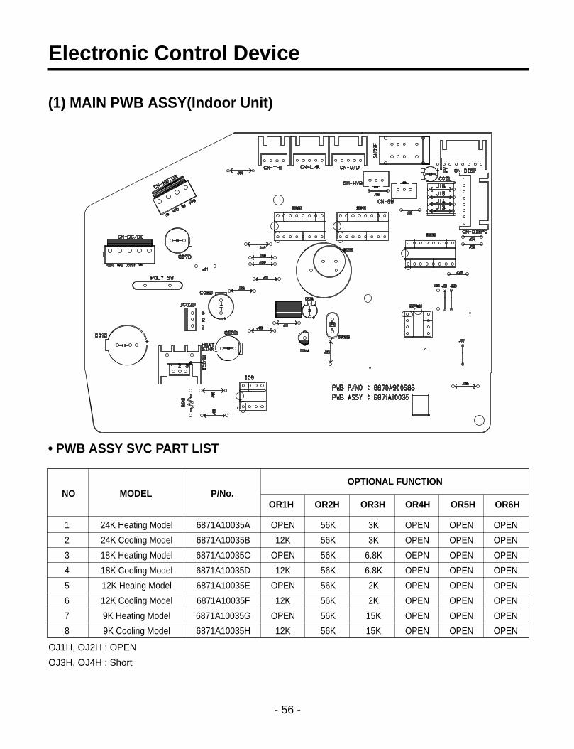
(1) MAIN PWB ASSY(Indoor Unit)
• PWB ASSY SVC PART LIST
- 56 -
Electronic Control Device
1 24K Heating Model 6871A10035A OPEN 56K 3K OPEN OPEN OPEN
2 24K Cooling Model 6871A10035B 12K 56K 3K OPEN OPEN OPEN
3 18K Heating Model 6871A10035C OPEN 56K 6.8K OEPN OPEN OPEN
4 18K Cooling Model 6871A10035D 12K 56K 6.8K OPEN OPEN OPEN
5 12K Heaing Model 6871A10035E OPEN 56K 2K OPEN OPEN OPEN
6 12K Cooling Model 6871A10035F 12K 56K 2K OPEN OPEN OPEN
7 9K Heating Model 6871A10035G OPEN 56K 15K OPEN OPEN OPEN
8 9K Cooling Model 6871A10035H 12K 56K 15K OPEN OPEN OPEN
NO MODEL P/No.OPTIONAL FUNCTION
OR1H OR2H OR3H OR4H OR5H OR6H
OJ1H, OJ2H : OPEN
OJ3H, OJ4H : Short

1 12K Heaing Model 6871A10036E 6.8K 5.1K 1K OPEN 39K O O O O O O
2 12K Cooling Model 6871A10036F 6.8K 5.1K 1K OPEN 39K X X X X X X
3 9K Heaing Model 6871A10036G 6.8K 10K 6.8K 3K OPEN O O O O O O
4 18K Heaing Model 6871A10036C 6.8K 10K 5.1K 6.8K 12K O O O O O O
5 18K Cooling Model 6871A10036D 6.8K 10K 5.1K 6.8K 12K X X X X X X
6 24K Heaing Model 6871A10036A 3K 2K 6.8K OPEN 3K O O O O O O
7 24K Cooling Model 6871A10036C 3K 2K 6.8K OPEN 3K X X X X X X
8 9K Cooling Model 6871A10036H 6.8K 10K 6.8K 3K OPEN X X X X X X
- 57 -
(2) MAIN PWB ASSY(Outdoor Unit)
• PWB ASSY SVC PART LIST
NO MODEL P/No.OPTIONAL FUNCTION
OR4H OR5H OR6H OR7H OR 8H FUSE RY-HEATER
RY-4WAY RY-FAN CN-
4WAYCN-FAN CN-TH
125V3.15A
250V3.15A

(3) DISPLAY PWB ASSY
- 58 -
<9K, 12K, 18K, 24K>
(P/No: 6871A30009C)

1. Indoor Unit
- 59 -
Schematic Diagram
64 17
12 1614 1513
Ope
ratio
n
CM
P
Tim
er
Sle
ep
7 98 11104 65321
37
31.
2419
2223
2021
1825
2629
2728
3032
3335 3436
5057
6261
6359
5860
5654
5552
5351
41 4042 383945 44 4347 46
49
48
PO
LY S
WR
XE
250
Opt
ion
C04
D
DC
12V
Vss
0
Vdd
0
SW
01F
CN
-SW
Opt
ion
SW
ITC
HLI
MIT
NO
NC C
OM
3 2 1
3 2 1
FO
RC
ED
OP
ER
AT
ION
RE
MO
TE
CO
NT
RO
L
AU
TO
RE
ST
AR
T3 124
5V
C05
D
25V
470u
FC
06D
103
+10
450
V
OJ2
H
DC
5V
R11
H
OJ1
H
7805
IC02
DO
I
OJ4
HO
J3H
R11
H~
R14
H20
K
20K
R06
F
5V
20K
R04
F20
KR
02F
8 ST
93C
46C
B6
567
R12
H
R14
H
R13
H
EE
PR
OM
93C
46B
SV
cc
QV
ss
DC
OR
G
DU
1 2 43
5V
CN
-U/D
10V
220
C02
L
CN
-DIS
P
RE
CE
IVE
R
Vcc
Vou
t
GN
D
116254
LED
1
LED
4
LED
3
2 64 5
371
LED
2
RD
7 31
3 24
YL
OR
PK
3 24
(UP
/DO
WN
)
5B
L5
13 101216 1415
rece
iver
11
R01
G~
R04
G22
0
9
6 74 532
5V
KID
6500
4AF
KID
6500
4AF
IC01
G
18IC01
M
9
HV
B O
UT
85 6 741 2 3
1R
02A
,20K
5V
R11
H~
R16
H12
.1K
DC
5V
C02
D+
C03
D
25V
470u
FC
01D
35V
2200
uF
+10
450
V
7812
IC01
DO
I
3
10K
R97
10K
2
R96
IC9-
1K
A39
3
-4
DC
12V
+8
1
R95
10K
RE
SE
T
AV
dd
AV
ref
OR
6HH
iM
edO
R5H
A V 1dd
5V
s sA V
OR
1HO
/LO
R3H
OR
4HLo
wF
2O
R2H
F1R
21H
R26
H
R25
H
R24
H
5V
R23
H
R22
H
C01
A
25V
0.01
C02
A22
010
V
3
DC
5V
CN
-MO
TO
R
MO
TO
R
IND
OO
RF
AN
34
34
1 1
2 2
63V
100u
F+
~
C07
D
1%
IC01
AK
IA70
36P
KS
C75
36
23.6V
10K
DC
12V
R05
H
R02
HR
04H
1%
6.
2K
1%12
.1K5V
PK
M13
EP
P-4
002
BZ
01E
CS
T-8
.00M
TW
rece
iver
16
Z
7
10
B
611
45
1312
13
2
1415
R81
1K
R01
B,1
M
X1
X2
Vss
1
5V
INT
0
INT
110
3C
81
R01
E1K R
02L,
1K
5V
R01
L5.
1K
KID
6500
4AF
IC02
M
89
C01
L 68
0pF
50
V
R02
E,2
0
CN
-L/R
(LE
FT
/RIG
HT
)
BL
22
OR
PK
YL
34
34
RD
511
5
ST
EP
PIN
G M
OT
OR
Opt
ion
R90
1K
DC
5V
5V
OS
C01
B10
3C
91
7
IC9-
2K
A39
3
-5
4.7K
R91
+
R92
10K
6
R93
10K
HV
B O
UT 12
V
33
33
CN
-DC
/DC
4 5
4 5
44
PIP
E-T
H
R99
C92
750
1/4W
104,
50V
1 2
1 2
11
CN
-TH
1 34 224 3
RO
OM
-TH
21
21
HV
B O
UT
CN
-HV
B
3 2 1
3 2 1
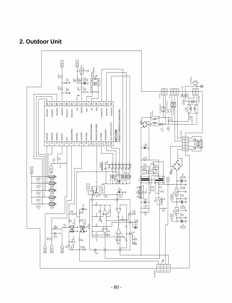
2. Outdoor Unit
- 60 -
3
21
IC9
IC10
5
TLP
521-
1BL
TLP
521-
1BL
CN
-DC
/DC 42 31
470u
F20
V
C05
42 31
82 3
220
VR
71R
75
23.2
K
1%2K
100u
F25
V
C73
+
4 R74
5.1K
87
29.4
K
20K
34K
1.06
K
102
1
-+
-
D92
C92
50V
1N41
48
8
104
IC7
5.23
K13
K3K
3 +14
9
HC
P60
68
56R95
D91
1N41
48
34
21
21
34
2.7K
R92
DC
5V
DC
5V
DC
5V
ZD
815.
1V
R91
1K
6.8K
1%R82
R81
X
XX
1%
NT
C1
DK
S-8
0-13
ZN
R1
INR
14D
471K
35V
2200
uF
+
103
C06
470u
F25
V
C03
+
104
C02
50V
103
C04
C01
+
C66
63V
2SD
2220
680u
F
IC3
7805
100K
R68
5V
OI
10K
R64
Q62
C67
100V
473K
+
R67 I1.5K
7812
IC2
O
12V
103K
100V
C60
49
17V
102J
,100
VC
69C
68
821K
,1K
VC
65
2 37
ST
2
84
4
PO
WE
R T
RA
NS
91
35
64
7
56
34
1
3
CN
-TR
AN
S
1
S1V
B60
BD
01
C62
1KV
222K R65
D
61 E
RB
44-0
8 30,1
WQ
612S
K26
71
ZD
6112
V
R66
200
101K
1KV
C63
68K
3WR63
R62
1/2W
560K
100u
F
+C
61
450V
AC
230V
/60H
zF
US
E25
0V/3
.15A
150-
F06
MC
OIL
1
CN
-PO
WE
R
11
G4A
-1A
RY
-CO
MP
WX
E-3
34K
N/F
ILT
ER
1
33
RY
-FA
N,4
WA
Y,H
EA
TE
R
RY
-4W
AY
,G5N
-1A
RY
-HE
AT
ER
RY
-FA
N
G5N
-1A
CO
IL2
LS40
4060
CN
-4W
AY
CN
-FA
N
34
34
11
3 1
3 1
GM
S81
C14
08S
K(H
YU
ND
DA
I:8K
)
TM
R20
V/R
B7
SR
DY
IN/S
RD
YO
UT
/RC
3
AN
0/A
ref/R
B0
PW
M0/
CO
MP
0/R
B4
PW
M1/
CO
MP
1/R
B5
R97
1K
RY
-HE
AT
ER
RY
-CO
MP
RY
-FA
N
R96
620
RY
-4W
AY
10
6
100V
102J
C72
R73
13K
1%
16.04
K
22
51.1
K
2-
45
-+
L61
L62
FM
X12
SL6
3L6
4
D62
11
ST
1
2
100U
fR
7211
K1%
C71
+
25V
10.2
K1%
LED
92
7
21.5
K
39.2
K
35.7
K
+11
4.3K
13
103
C91
R94
180
R93
390
1KR90
LED
91
DC
12V
KR
A10
2M
DC
5V
R71
Q71
139
9
8
15 16
2 1
12 13 1411
4 356
MIC
OM
14
IC01
MK
ID65
004A
PK
ID65
004A
P
11 1210
EC
1/R
B6
8 96 7
INT
O/R
B2
INT
1/R
B3
BU
Z/R
B2
12.1
KR
27 1%
OR
7O
R8
1%X
XX
XX
X1%
R28
12.1
K 1%
OR
5O
R4
OR
6X
XX
1%X
XX
1%1%
XX
X
12.1
KR
25R
2412
.1K 1%
12.1
K1%
1%
R26
DC
5V
TH
11KR
32H
R31
H12
.1K
2 4 53
AN
7/R
A7
Vdd
AN
6/R
A6
AN
5/R
A5
1A
N4/
RA
4
DC
5V
+R02
A10
K
16
BD
61U
4SB
A60
RC
4/S
CK
RC
5/S
IN
1521 1719 182023 22
Xou
t
RC
6/S
OU
T
RD
2
Xin
RD
0/IN
T2
RE
SE
T
Vss
R01
B 1
M
R01
A
C01
A10
3
1K
50V
CS
T-4
.00M
TW
OS
C01
B7036
P
R03
A10
0 C02
A10
uF
IC4DC
5V
25 242628 27
RD
1/IN
T3
RA
0/E
C0
RA
1/A
N1
RA
2/A
N2
RA
3/A
N3
10K
C11
H10
3R11
H10
K
KE
YT
ES
T
R12
H
DC
5V

1. Indoor Unit (9K)
- 61 -
Exploded View and Replacement Parts List
2671
10
2499
51
3542
12
1353
12
1353
11
3590
11
1314
1073
3010
3428
00
2687
12
1523
02
1599
0126
3230
2687
14
3521
50
3468
1035
211B
1353
14
1468
11
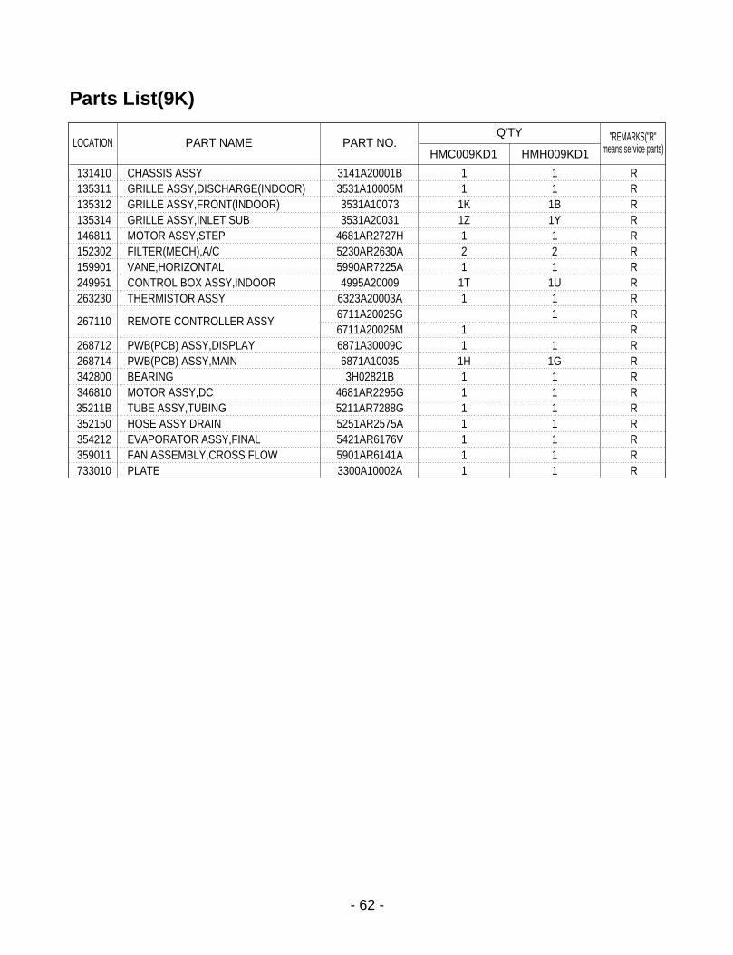
- 62 -
Parts List(9K)
131410 CHASSIS ASSY 3141A20001B 1 1 R135311 GRILLE ASSY,DISCHARGE(INDOOR) 3531A10005M 1 1 R135312 GRILLE ASSY,FRONT(INDOOR) 3531A10073 1K 1B R135314 GRILLE ASSY,INLET SUB 3531A20031 1Z 1Y R146811 MOTOR ASSY,STEP 4681AR2727H 1 1 R152302 FILTER(MECH),A/C 5230AR2630A 2 2 R159901 VANE,HORIZONTAL 5990AR7225A 1 1 R249951 CONTROL BOX ASSY,INDOOR 4995A20009 1T 1U R263230 THERMISTOR ASSY 6323A20003A 1 1 R
267110 REMOTE CONTROLLER ASSY6711A20025G 1 R6711A20025M 1 R
268712 PWB(PCB) ASSY,DISPLAY 6871A30009C 1 1 R268714 PWB(PCB) ASSY,MAIN 6871A10035 1H 1G R342800 BEARING 3H02821B 1 1 R346810 MOTOR ASSY,DC 4681AR2295G 1 1 R35211B TUBE ASSY,TUBING 5211AR7288G 1 1 R352150 HOSE ASSY,DRAIN 5251AR2575A 1 1 R354212 EVAPORATOR ASSY,FINAL 5421AR6176V 1 1 R359011 FAN ASSEMBLY,CROSS FLOW 5901AR6141A 1 1 R733010 PLATE 3300A10002A 1 1 R
LOCATION PART NAME PART NO. "REMARKS("R"means service parts)
Q'TY
HMC009KD1 HMH009KD1
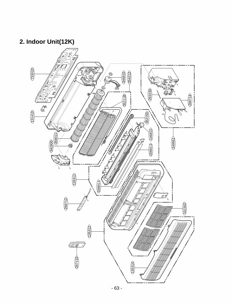
2. Indoor Unit(12K)
- 63 -
2671
10
2499
51
3542
12
1353
12
1353
11
3590
11
1314
1073
3010
3428
00
2687
12
1523
02
1599
01-2
1599
01-1
2632
30
2687
14
3521
50
3468
1035
211B
1353
14
1468
11

Parts List(12K)
- 64 -
131410 CHASSIS ASSY 3141A20003D 1 1 R
135311 GRILLE ASSY, DISCHARGE(INDOOR) 3531A10023T 1 1 R
135312 GRILLE ASSY, FRONT 3531A10030 1Y 1Z R
135314 GRILLE ASSY, INLET 3531A10032 1W 1X R
146811 MOTOR ASSY, STEP 4681AR2727H 1 1 R
152302 FILTER(MECH), A/C 5230A20004A 2 2 R
159901-1 VANE,HORIZONTAL 5990A30006A 1 1 R
159901-2 VANE,HORIZONTAL 5990A30007A 1 1 R
249951 CONTROL BOX ASSY, INDOOR 4995A20143 1N 1P R
263230 THERMISTOR ASSY 6323A20003A 1 1 R
267110 REMOTE CONTROLLER ASSY 6711A20025M 1 1 R
268712 PWB(PCB) ASSY, DISPLAY 6871A30009E 1 1 R
268714 PWB(PCB) ASSY, MAIN 6871A10035 1F 1E R
342800 BEARING 3H02821B 1 1 R
346810 MOTOR ASSY, DC 4681AR2295H 1 1 R
35211B TUBE ASSY, TUBING 5211AR7066B 1 1 R
352150 HOSE ASSY, DRAIN 5251AR2575A 1 1 R
354212 EVAPORATOR ASSY, FINAL 5421A20031X 1 1 R
359011 FAN ASSY, CROSS FLOW 5901AR6141C 1 1 R
733010 PLATE ASSY, INSTALL 1H00843A 1 1 R
LOCATION PART NAME PART No.Q/TY
HMC012KD1 HMH012KD1
REMARKS("R" means
service parts)

- 65 -
2. Indoor Unit(18K, 24K)13
1410
2671
10
2499
51
1353
12
1353
11
3542
12
3590
11
7330
10
3428
00
2687
12
1523
02
1599
01-2
1599
01-1
2632
30
2687
14
3521
50
3468
1014
6811
1468
11
1353
14

- 66 -
Parts List(18K, 24K)
131410 CHASSIS ASSY 3141A20002D 1 1 1 1 R
135311 GRILLE ASSY, DISCHARGE(INDOOR) 3531A10008R 1 1 1 1 R
135312 GRILLE ASSY, FRONT(INDOOR) 3531A10026 1X 1Y 1X 1Y R
135314 GRILLE ASSY, INLET SUB 3531A20032 1R 1S 1R 1S R
146811 MOTOR ASSY, STEP 4681AR2727H 1 1 1 1 R
152302 FILTER(MECH), A/C 5230A20001A 2 2 2 2 R
159901-1 VANE, HORIZONTAL 5990A30001A 1 1 1 1 R
159901-2 VANE, HORIZONTAL 5990A30002A 1 1 1 1 R
249951 CONTROL BOX ASSY, INDOOR 4995A20123 1U 1V 1W 1X R
263230 THERMISTOR ASSY 6323A20003A 1 1 1 1 R
267110 REMOTE CONTROLLER ASSY 6711A20025M 1 1 R
6711A20026T 1 1 R
268712 PWB(PCB) ASSY, DISPLAY 6871A30009D 1 1 1 1 R
268714 PWB(PCB) ASSY, MAIN 6871A10035 1D 1C 1B 1A R
342800 BEARING 3H02821B 1 1 1 1 R
346810 MOTOR ASSY, DC 4681AR2295J 1 1 1 1 R
35211B TUBE ASSY, TUBING 5211A30038 1C 1C 1D 1D R
352150 HOSE ASSY, DRAIN 5251AR2575A 1 1 1 1 R
354212 EVAPORATOR ASSY, FINAL 5421A20021 1D 1T 1E 1E R
359011 FAN ASSY, CROSS FLOW 5901AR2441 1D 1E 1D 1E R
733010 PLATE ASSY, INSTALL 1H00843A 1 1 1 1 R
LOCATION PART NAME PART No.Q/TY
HMC018KD1 HMH018KD1 HMC024KD1 HMH024KD1
REMARKS("R" means
service parts)

- 67 -
5501
40
5541
60
5675
02
5521
16
5614
10
5530
00
5521
1143
7210
5590
10
5468
10
5540
31
2617
04 W0C
ZZ
4304
10
5522
03-3
5522
03-1
4372
12
4355
11
5522
02
6499
50
6687
11
4. Outdoor Unit(9K, 12K)

Parts List(9K, 12K)
- 68 -
552116 TUBE ASSY,REVERSING 5211A20140 1F 1G R552202 VALVE,REVERSING 5220AR3084B 1 1 R
552203-1 VALVE,SERVICE 2H02479H 1 1 R5220A20005A 1 1 R
552203-3 VALVE,SERVICE 2H01890L 1 1 R5220A20003A 1 1 R
553000 HEATER,SUMP 5300AR2915D 1 1 R554031 CONDENSER ASSY,BENT 5403A20019 1B 1P R
5403A20026 1D 1B R554160 COMPRESSOR SET 2520UKAC2BA 1 R
2520UKWC2FA 1 R2520UKCC2AA 1 R2520UKSC2AA 1 R
559010 FAN ASSY,PROPELLER 5901A10004A R561410 COIL ASSY,REVERSING VALVE 6141AR3851G 1 1 R567502 O.L.P 6750U-L029A 1 R
6750U-L031A 1 R6750U-L046A 1 R6750U-L049A 1 R
649950 CONTROL BOX ASSY,OUTDOOR 4995A10038 1A 1B 1C 1D R668711 PWB(PCB) ASSEMBLY,MAIN(OUTDOOR) 6871A10036 1H 1G 1F 1E RW0CZZ CAPACITOR,DRAWING 0CZZA20001 1N 1L R
6120AR2194 1F 1K R552111 TUBE ASSY,CAPILLARY 5211A20095F 1 R
5211A20141 1A 1D R5211A20133D 1 R
261704 TRANSFORMER,POWER 6171AQ3198B 1 1 1 1 R430410 BASE ASSY,OUTDOOR 3041A20008 1J 1F 1D 1F R435511 COVER ASSY,CONTROL(OUTDOOR) 3551AR7184R 1 1 1 1 R437210 PANEL ASSEMBLY,FRONT(OUTDOOR) 3721A20027B 1 1 1 1 R437212 PANEL ASSY,REAR(OUTDOOR) 3721A20026 1A 1B 1A 1B R546810 MOTOR ASSY,OUTDOOR 4681A20004R 1 1 1 1 R550140 ISOLATOR,COMP 4H00982E 3 3 3 3 R
LOCATION PART NAME PART NO. "REMARKS("R"means service parts)
Q'TY
HMC009KD1 HMH009KD1 HMC012KD1 HMH012KD1

5. Outdoor Unit(18K)
- 69 -
5521
16
6499
50
5614
10
5541
60
5675
02
4479
10
5501
40
5522
03-2
5522
03-3
4355
12
4372
10
5590
10
5468
10
6687
115521
11
W0C
ZZ
5540
31
2617
04
4372
12 4355
11
5530
0043
0411

Parts List(18K)
- 70 -
261704 TRANSFORMER, POWER 6171AQ3178A 1 1
430411 BASE ASSY, WELD(OUTDOOR) 3041A30003F 1 1 R
435511 COVER ASSY, CONTROL(OUTDOOR) 3551AR7184T 1 1 R
435512 COVER ASSY, TOP(OUTDOOR) 3H03266J 1 1 R
437210 PANEL ASSY, FRONT(OUTDOOR) 3721A20005B 1 1 R
437212 PANEL ASSY, REAR 3720AP0003D 1 1 R
546810 MOTOR ASSY, OUTDOOR 4681A20013M 1 1 R
550140 ISOLATOR, COMP 4H00982E 3 3 R
552111 TUBE ASSY, CAPILLARY 5425AR3847L 1 R
5211A10039B 1 R
552116 TUBE ASSY, REVERSING 5211A30042J 1 R
552202 VALVE, REVERSING 3A02027D 1 R
552203-2 VALVE, SERVICE 2A00392E 1 1 R
552203-3 VALVE, SERVICE 2H02479 1B 1F R
553000 HEATER, SUMP 5300AR2915A 1 R
554031 CONDENSER ASSY, BENT 5403A20022 1B 1F R
554160 COMPRESSOR SET 2520UMLK1BA 1 R
2520UMBK1BA 1 R
559010 FAN ASSY, PROPELLER 1A00195B 1 1 R
561410 COIL ASSY, REVERSING VALVE 3A02028H 1 R
567502 O.L.P 6750U-L025A 1 R
649950 CONTROL BOX ASSY, OUTDOOR 4781AR1528 1Q 1R R
668711 PWB(PCB) ASSY, MAIN(OUTDOOR) 6871A10036 1D 1C R
W0CZZ CAPACITOR, DRAWING 6120AR2194 1B 1F R
LOCATION PART NAME PART No.Q/TY
HMC018KD1 HMH018KD1
REMARKS("R" means
service parts)

5. Outdoor Unit(24K)
- 71 -
6499
50
5521
11
6687
11
W0C
ZZ
5501
4055
3000
5521
16
5522
02
5614
40
5522
03-3
5522
03-1
4355
11
4304
11
4355
12
5540
3143
7212
4372
10
5590
10
5468
11
5540
31
2617
04

Parts List(24K)
- 72 -
261704 TRANSFORMER, POWER 6171AQ3198A 1 1 R
430411 BASE ASSY, WELD(OUTDOOR) 3041A30003U 1 1 R
435511 COVER ASSY, CONTROL(OUTDOOR) 3551AR7184T 1 1 R
435512 COVER ASSY, TOP(OUTDOOR) 3H03266J 1 1 R
437210 PANEL ASSY, FRONT(OUTDOOR) 3721A20005B 1 1 R
437212 PANEL ASSY, REAR 3720AP0003D 1 1 R
546811 MOTOR ASSY, OUTDOOR 4681A20013N 1 1 R
550140 ISOLATOR, COMP 4H00637A 3 R
5040A30017B 3
552111 TUBE ASSY, CAPILLARY 5425AR3847Q 1 R
5211A10039J 1 R
552116 TUBE ASSY, REVERSING 5221AR2938Y 1 R
552202 VALVE, REVERSING 3A02027D 1 R
552203-1 VALVE, SERVICE 2A00393C 1 1 R
552203-3 VALVE, SERVICE 2A00392E 1 1 R
553000 HEATER, SUMP 5300AR2915A 1 R
554031 CONDENSER ASSY, BENT 5402AR2347Z 1 R
5403A20051B 1 R
554160 COMPRESSOR ASSY, FINAL 5417A20012N 1 1 R
559010 FAN ASSY, PROPELLER 1A00195B 1 1 R
561440 COIL ASSY, REVERSING VALVE 3A02028H 1 R
649950 CONTROL BOX ASSY, OUTDOOR 4781AR1528 1S 1T R
668711 PWB(PCB) ASSY, MAIN(OUTDOOR) 6871A10036 1B 1A R
W0CZZ CAPACITOR, DRAWING 6120AR2359U 1 1 R
LOCATION PART NAME PART No.Q/TY
HMC024KD1 HMH024KD1
REMARKS("R" means
service parts)

P/No.: 3828A20048M Printed in Korea