Embed Size (px)
Citation preview

DENTSPLY CeramcoYucaipa, CA
Service Instructions
VULCAN
A-130 3-130 3-550PDA550 3-550 3-550AA-1750 3-1750 3-1750A

SAFETY FIRST* Don�t bypass the power cord�s ground lead with two-wire extension cords
or plug adaptors.
* Don�t disconnect green/yellow safety-earth ground wire that connects theground lug of the power receptacle to the chassis ground.
* Don�t plug in the power cord until directed by the installation instructions.
* Don�t repair the furnace unless you are a qualified technician and knowhow to work with hazardous voltages.
* Don�t locate and operate the furnace in close proximity to combustiblematerials.
* Observe all WARNING statements. They point out situations that cancause injury or equipment damage.

TABLE OF CONTENTSSECTION 1
CIRCUIT DESCRIPTION A-CONTROL
1.1 INTRODUCTION ...............................................1-11.2 CIRCUIT DESCRIPTION ..................................1-11.2.1 Analog Meter Readout ......................................1-11.2.2 Front Panel Controls ........................................1-11.2.3 Muffle Control ....................................................1-11.2.4 Power Supply ....................................................1-1
SECTION 2TROUBLESHOOTING A-CONTROL
2.1 FACTORY REPAIR ............................................2-12.2 BEFORE YOU START .......................................2-12.3 TROUBLESHOOTING GUIDES ........................2-12.3.1 Power Supply ....................................................2-12.3.2 Analog Circuitry .................................................2-12.3.3 Triac Drive .........................................................2-12.4 TROUBLESHOOTING COMPONENTS ............2-12.5 BLOCK DIAGRAM .............................................2-32.6 SCHEMATIC ......................................................2-42.7 CONTROL CIRCUIT BOARD ...........................2-52.8 WIRING DIAGRAM ............................................2-6
SECTION 3CALIBRATION A-CONTROL
3.1 SCOPE ..............................................................3-13.2 FACTORY REPAIR ............................................3-13.3 ADJUSTMENTS ................................................3-13.3.1 Door, Lift Drag Adjustment ...............................3-13.4 CIRCUIT BOARD CALIBRATION ......................3-13.4.1 Required Test Equipment ................................3-13.4.2 Temperature .....................................................3-1
SECTION 4CIRCUIT DESCRIPTION 3-STAGE
4.1 INTRODUCTION4.2 CIRCUIT DESCRIPTION ..................................4-14.2.1 LCD Display Readout .......................................4-14.2.2 Front Panel Control ..........................................4-14.2.3 Muffle Control ....................................................4-14.2.4 Power Supply ....................................................4-14.2.5 Motor Drive Control ...........................................4-14.2.6 Fan Drive Control ..............................................4-1
SECTION 5TROUBLESHOOTING 3-STAGE
5.1 FACTORY REPAIR ............................................5-15.2 BEFORE YOU START .......................................5-15.2.1 Isolating a Problem ..........................................5-15.3 TROUBLESHOOTING GUIDES ........................5-15.3.1 Power Supply ....................................................5-15.3.2 Microprocessor .................................................5-15.3.3 Peripheral Drive ................................................5-15.3.4 Motor Drive ........................................................5-15.3.5 Analog Circuitry .................................................5-15.3.6 Display Board ...................................................5-15.3.7 Fan Drive Control ..............................................5-2
5.4 TROUBLESHOOTING COMPONENTS ............5-25.5 ERROR CODES ...............................................5-35.6 DIAGNOSTIC TABLES ......................................5-45.7 BLOCK DIAGRAM .............................................5-85.8 SCHEMATICS ...................................................5-95.9 WIRING DIAGRAM ............................................5-12
SECTION 6ADJUSTMENT/CALIBRATION 3-STAGE
6.1 SCOPE ..............................................................6-16.2 FACTORY REPAIR ............................................6-16.3 ADJUSTMENT/CALIBRATION ..........................6-16.3.1 Temperature .....................................................6-16.3.2 Door, Lift Drag Adjustment ...............................6-16.4 CIRCUIT BOARD CALIBRATION ......................6-16.4.1 Required Test Equipment ................................6-16.4.2 Temperature .....................................................6-1
SECTION 7SERVICE PARTS
7.1 ORDERING INSTRUCTIONS ..........................7-17.2 MUFFLE AND THERMOCOUPLE.....................7-17.3 MUFFLE (3-550 PD / AIR EXCH) .......................7-27.4 CABINET PARTS ..............................................7-37.5 DOOR PARTS ...................................................7-47.6 A-CONTROLLER PARTS.................................7-57.7 3-STAGE & 3-550 CONTROLLER PARTS .......7-67.8 LIFT MECHANISM PARTS (3-550PD) ..............7-7
SECTION 8DISASSEMBLY/REASSEMBLY
8.1 CONTROL DRAWER REMOVAL ......................8-18.2 TRIAC ................................................................8-18.3 MEMBRANE SWITCH .......................................8-28.4 DISPLAY PCB ...................................................8-38.5 A-CONTROL PCB .............................................8-48.6 3 STAGE CONTROL PCB.................................8-58.7 DOOR ASSEMBLY/ADJUSTMENT ...................8-68.8 HEATING PLATES ............................................8-78.9 MUFFLE REPLACEMENT........................ ...........8-88.10 THERMOCOUPLE (A-Control) .........................8-98.11 THERMOCOUPLE (3 STAGE) ..........................8-98.12 MUFFLE REPLACEMENT(3-550 PD)........ .......8-108.13 THERMOCOUPLE (3-550PD) ..........................8-118.14 POWER SWITCH ..............................................8-128.15 POWER DOOR REPLACEMENT .....................8-13

1-1
SECTION 1CIRCUIT DESCRIPTION
A-CONTROL1.1 INTRODUCTION
The purpose of this section is to familiarize the user orservice personnel with the circuit level operation of theVULCAN. This knowledge is necessary to aid in trouble-shooting of a unit's failure and may also allow the userto gain greater insight into the VULCAN�s versatility forparticular applications. A detailed description is given forthe following circuit functions:
*Analog Meter Readout*Front Panel Controls*Muffle Control*Power Supply
1.2 CIRCUIT DESCRIPTION
1.2.1 Analog Meter ReadoutThe Type K thermocouple which extends from the backof the muffle is directly connected to an analog meterwhich provides the operator with the present muffletemperature. The yellow lead of the thermocouple isconnected to the + input of the meter.
1.2.2 Front Panel ControlsThe power on/off switch provides AC line voltage to thefurnace if the door switch is closed, while the setpointpotentiometer (10K) provides the electronics with areference voltage which determines the final muffletemperature.
1.2.3 Muffle ControlThe muffle is controlled by means of a triac. This muffletriac may be activated anytime when the AC cycle goesthrough zero, and once activated it will only be openedagain when the AC sine wave passes through 0 volts.Thetriac is controlled by a Zero Voltage Switch (integratedcircuit U2) and is configured as a proportionalcontroller.Trigger pulses are generated when the com-parator detects Vpin3 is above the Vref. The sensedtemperature from the amplified thermocouple signal isthen lower than the set value of RP2. As Vpin3 is nearin value of Vref, a proportional control takes over, i. e.power is delivered by bursts to the load.
To slow down the heatup time of the muffle (RP2 setclockwise and muffle is at low temperature) a ratecontrol potentiometer (RP3) has been added to thecircuitry. A sawtooth signal from pin2 of U2 is comparedwith a fixed reference voltage which can be set by RP3.As the sawtooth voltage exceeds the value of the fixedreference voltage, amplifier U3 produces a negativeoutput which in turn increases the thermocouple signaloutput from U1 and Vpin3 of U2 and is now more negativethan Vref, thus the triac output pulses stop.
1.2.4 Power SupplyThe rectified supply current (D2) is zener regulated to8.6V and biased by dropping resistors R11, R12.The positive voltage to U1 and U2 is provided by a 6.8Vzener diode D1.
I
Load Current - Proportional Control
t
T
NOTES:

2.1 FACTORY REPAIR
DENTSPLY Ceramco maintains a factory repair depart-ment for those customers not possessing the necessarypersonnel or test equipment to maintain the VULCAN. Ifa unit is returned to the factory for calibration or repair, adetailed description of the specific problem should beattached to minimize turnaround time. Call factory forRMA number before shipping at 909.795.2461.
2.2 BEFORE YOU STARTSince no troubleshooting guide can possibly cover all thepotential problems, the aim of this guide is to give amethodology which, if applied consistently, will lead tothe problem area. Therefore , it is necessary to familiarizeyourself with the VULCAN by reviewing the functionaldescription in conjunction with the schematic. Success-ful troubleshooting depends upon understanding thecircuit operation.
WARNING:With covers removed, dangerous voltagepoints may be exposed. Contact with anyof these points could cause serious injury.
2.3.3 Triac Drive A current pulse from U2 pin 6 of about 60mA will turn onthe gate of the muffle triac which in turn will then carry thefull load current. The voltage across the triac is now at1-2 Vac. In order to comply with norms limiting thefrequency at which a kW size load may be connected tothe main line (fluorescent tubes "flickering") a propor-tional temperature control is provided by means of burstfiring the triac.
NOTES:
SECTION 2TROUBLESHOOTING
A-CONTROL
2.3 TROUBLESHOOTING GUIDES
WARNING:When measuring voltages use batteryoperated test equipment unless an isolationtransformer is connected between circuitinput and AC line.
2.3.1 Power SupplyRectifier diodes D2 and D3 convert the AC line voltageto a DC voltage, while resistors R11, R12 reduce thecurrent flow thru the 8.6V internal zener diode of U2 andthe 6.8V external zener diode D1. Capacitors C1 and C5filter the rectified voltages. Most of the circuit's currentconsumption is taken up by the triac gate drive.
2.3.2 Analog CircuitryThe thermocouple voltage which ranges from 0-45mV(25°C - 1100°C) is multiplied by amplifier U1 approxi-mately 100 times (depending on the setting of potenti-ometer RP1) and added to the negative setpoint voltagefrom RP2. A sawtooth voltage signal is generated by U2from a constant current source charging capacitor C4.The value of C4 determines the burst period of the triacoutput (typically 8 seconds). The triac gate output pulsecurrent is about 60mA. The triac is triggered in quadrantsII and III. Synchronization is provided by resistor R10. Itsvalue determines the trigger pulse length.
2.4 TROUBLESHOOTING COMPONENTS
2.4.1 DiodeA diode (except a zener) is defective if there is greaterthan 1 Vdc (typically 0.7 Vdc) forward voltage across it.
2.4.2 Operational AmplifierGenerally, the �+� and �-� inputs of an operational ampli-fier will have less than 15 mV voltage difference whenoperating under normal conditions. If the output voltagestays at maximum positive (typically 1/3 of the supplyvoltage), the �+� input voltage should be more positive thanthe �-� input voltage. If the output voltage stays at minimum(typically 1-5 mV), the �-� input voltage should be morepositive than the �+� input voltage.
2.4.3 TriacThe gate to power line return voltage under load mea-sures typically 1-2 Vac, while the MT2 to return voltagemeasures between 1.3-1.8 Vac. A triac without connec-tions and no power applied can be checked for a go-nogo condition with an ohmmeter. The gate to MT1 resis-tance for a power triac (20-40A) should be between 50and 100 ohms; there should be infinite resistance be-tween MT1 and MT2.
2-1
2.4.4 CapacitorShorted capacitors have 0V across their terminals.Open capacitors can be located by using a good capaci-tor connected in parallel with the capacitor under test andobserving the resulting effect.

Leaking capacitors will often have a decreased voltageacross their terminals.
NOTES:
A-CONTROL
2-2

Amplifier U1
2-3
Feedback
Power Triac 25A, 400V
Muffle
Return Cabinet
-8.6V+6.8V
A-CONTROL
Triac Driver U2
Comparator,Power Supply,
Set Point PotRate Control Pot
2.5 BLOCK DIAGRAM
Power SupplyD1,C1,R11
Thermocouple
120/240V 60/50Hz Line

2.6 SCHEMATIC
2-4
A-CONTROL
Tria
c
Hea
ting
Pla
te
A13
0 &
A55
0 O
NLY
NO
TE:
A17
50 -
250
V,20
ALI
NE
CO
RD
.

MuffleConnections
2-5
A-CONTROL
Triac Gate
Proportional Control ICThermocoupleAmplifier
SetpointPotentiometer
Temperature MeterConnectionsRate Control
2.7 CONTROL CIRCUIT BOARD

123123123123123
123123123123123
REDYELL
+
ORN
ANALOG PANEL METER
BLK
AC1
AC2MT1MT2
BLK
WHT
230VLINE CORD
WHT
GRN/YELL
DOOR SAFETYSWITCH
GRN/YELL
TRIAC
TAN
230V HOOK UP
P1 P6
P1 P6
CABINET GND
230VRECEPTACLE
RED
2-6
SETPOINT ADJUST
POWER SWITCH
TOPTERMINALS
ROUTE ALL MUFFLEWIRES THRU HERE
CONTROLDRAWER GND
THERMOCOUPLE
TRIAC HEATSINK
WHTWHT
120V LINECORD
A-CONTROL
BLK
WHT/BLK
GATE
120VHOOK UP
AND 1750MUFFLE
230VA-1750
C D
C DA B
A
B
RELAY FOR A-1750 ONLY
2.8 WIRING DIAGRAM
HEATINGPLATE
NOTE: A1750 - 250V,20A LINE CORD.
AB

SECTION 3ADJUSTMENT/CALIBRATION
A-CONTROL
3-1
3.4.2 TemperatureDisconnect the power cord from the wall outlet and openthe control drawer. Connect the black lead of theohmmeter to the red thermocouple connection on tem-perature meter. Touch the red lead of the ohmmeter to theleg with a circle on R13. Adjust RP1 to read 1060 ohmson the ohmmeter.
On models A-550 rated at 120V the potentiometer RP3should be adjusted the following way:
Touch the black lead of the ohmmeter to pin 3 of U3 andthe red lead to the leg of R14 closest to the front panel.Adjust RP3 to read between 19 and 20 Kohm on theohmmeter. This adjustment limits the amount of currentgoing thru the muffle by about 15% in order to comply withsafety agency rulings. For all other models RP3 shouldbe fully clockwise.
As an alternate circuit board calibration, without the useof an ohmmeter, bring the furnace temperature to thedesired level. At steady state temperature insert athermocouple, connected to a temperature monitor, intothe exhaust opening of the furnace and after stabilizationread the muffle temperature. Compare this reading withthe temperature meter reading of the furnace. In severalsteps adjust RP1 to obtain equal readings. Allow ampletime between adjustment steps since only a few wattsare added/subtracted which each adjustment of RP1.
WARNINGWith control drawer opened, dangerous volt-age points may be exposed. Contact with anyof these points could cause serious injury.
Calibration of the VULCAN circuit board is performed inone single step.
3.4.1 Required Test Equipment
- Multimeter - Pot adjustment tool
3.4 CIRCUIT BOARD CALIBRATION
3.1 SCOPE
This section gives the procedures to be used for thecalibration and specification verification of the VULCAN.The furnace specifications are given in the Owner &Operator�s Manual.
3.2 FACTORY REPAIR
DENTSPLY Ceramco maintains a factory repair depart-ment for those customers not possessing the necessarypersonnel or test equipment to maintain the VULCAN. Ifa unit is returned to the factory for calibration or repair, adetailed description of the specific problem should beincluded to minimize turnaround time. Call factory forRMA number before shipping at 909-.795.2461.
3.3 ADJUSTMENTS
3.3.1 Door, Lift Drag AdjustmentThe lift drag force is controlled by a set of friction washerson each of the upper pivot arms. If the drag becomes toostiff (too hard to open and close furnace) or too loose anadjustment can be made using the following procedure:
Tools required: 5/32" Allen Wrench
- Turn the allen head screws on the upper side of thefurnace either clockwise to tighten or counterclockwiseto loosen the drag force.
NOTE: Equal adjustment should be made on each side Turn screws only 1/6 of a revolution at a time when making adjustment.
NOTES:

4.1 INTRODUCTION
The purpose of this section is to familiarize the user orservice personnel with the circuit level operation of theVULCAN. This knowledge is necessary to aid in trouble-shooting of a unit's failure and may also allow the user togain greater insight into the VULCAN�s versatility forparticular applications. A detailed description is given forthe following circuit functions:
* Display Readout* Front Panel Control* Muffle Control* Power Supply* Motor Drive Control (option for 3-Stage)*Temperature Measurement
The muffle temperature is derived from a Thermocouple(type "K") which generates an output voltage of up to50mV. This feedback signal is then manipulated by theelectronics to control the muffle temperature.
4.2 CIRCUIT DESCRIPTION 3-STAGE
4.2.1 LCD Display ReadoutThe display board converts serial data from the micropro-cessor to 8-bit parallel data. Each byte transferred iseither a command or a data byte depending on the stateof the two control bits RS and E (DIS ENA). The 16character LCD module is controlled by the microproces-sor via its Serial Peripheral Interface (SPI) port. Thedisplay is updated every 0.5 sec or when a correspondingfront panel key has been activated.
4.2.2 Front Panel ControlThe power on/off switch switches the AC line voltage.The membrane switches are arranged in a 8x4 matrix.The microprocessor scans the entire matrix every 50msec by setting one column at a time to a logic 0 andthen reading the rows. Once a contact closure has beendetected this value is stored.
4.2.3 Muffle ControlThe microprocessor (U10) sends a serial digital signal toan octal peripheral driver (U16) which in turn converts andlatches it to parallel data. This parallel data is then usedto drive several peripheral devices (See S006). U16-13 isconnected to an opto isolator (U8). The isolator's outputis connected to the gate of the muffle triac. The muffletriac may be activated anytime during an AC cycle, butonce activated it can only be opened when the AC sinewave passes through 0 volts. U10 accesses U16 0.5msec before zero crossing to turn the triac off. At this timea value calculated by the controlroutine determines how much time should elapse beforethe triac is turned on again.
4.2.4 Power SupplyTwo DC power supply voltages are generated on thecontrol circuit board; +12V and +5V. These voltages aregenerated from the AC line voltage.
4.2.4.1 +12V Supply:The transformer T1 provides an AC voltage with a groundreferenced center tap. This voltage is rectified by diodesD41 and D42 and filtered by capacitor C40. This providesunregulated positive DC voltage for the switching regula-tor U9. The capacitor C42 protects against high voltagetransients on the AC line that couple into the transformersecondary. The output U9-2 is a pulse train with a periodT of typically 19.2usec. The catch diode D43 is aSchottky device which provides a return path for the loadcurrent when the output switch is off. Inductor L2 andcapacitor C46 filter and stabilize the +12V dc voltage.
4.2.4.2 +5V Supply:Refer to schematic, page 5-9. DC voltage from the outputof U9 is used by the +5V linear regulator U7 to generatethe +5V. The capacitor C48 provides additional filtering.The constant current source U2 as well as the 1.23Vreference diode D1 generate their outputs from thissupply.
4.2.5 Motor Drive Control (3-550 PD)The +12VDC motor which moves the door vertically iscontrolled by a 16 pin motor controller/driver I.C. This I.C.provides all necessary functions for a complete closedloop system. A two wire cable connects the motor to the1 Amp H-bridge switch on the I.C. The microprocessor(U10) activates the H-switch through two input pins. Ifboth are low the motor will turn in one direction, if both arehigh the motor turns in the opposite direction. A third pinsends a signal from the motor controller/driver I.C. to themicroprocessor when the motor has stalled (up or downposition).
4.2.6 Fan Drive Control 3-550A/1750AThe air exchange fan is controlled by means of the frontpanel membrane switch. Speed selections are from0 - 9 (0 is off and 9 is highest speed). Speed 1 selectionchanges the air in the muffle twice a minute.
NOTES:
4-1
SECTION 4CIRCUIT DESCRIPTION
3-STAGE

5-1
SECTION 5TROUBLESHOOTING
3-STAGE5.1 FACTORY REPAIR
DENTSPLY Ceramco maintains a factory repair depart-ment for those customers not possessing the necessarypersonnel or test equipment to maintain the VULCAN. Ifa unit is returned to the factory for calibration or repair, adetailed description of the specific problem should beattached to minimize turnaround time. Call factory forRMA number before shipping at 909.795.2461.
5.2 BEFORE YOU START
Since no troubleshooting guide can possibly cover all thepotential problems, the aim of this guide is to give amethodology which, if applied consistently, will lead tothe problem area. Therefore , it is necessary to familiarizeyourself with the VULCAN by reviewing the functionaldescription and the detailed circuit description (Section4) in conjunction with the schematics (Section 5). Suc-cessful troubleshooting depends upon understanding thecircuit operation within each functional block as well asthe block relationships
WARNINGWith covers removed, dangerous voltagepoints may be exposed. Contact with anyof these points could cause serious injury.
The intent of this section is to provide the information toreturn the VULCAN to proper operation. Information isdivided into two parts. Part one contains the overallfurnace troubleshooting block diagram which is useful inisolating defective blocks within the furnace. Part twoconsists of a series of circuit guides , one for each blockshown in the block diagram, that provides settings andmeasurements for troubleshooting an individual block.Also, each circuit guide references related schematicsand circuit descriptions. Inspect the components, wiringand circuit boards of the VULCAN for damage. Finally,ensure that the fuses are intact and the internal powersupplies are good.
5.2.1 Isolating a problemTo successfully troubleshoot this furnace, the symptomsmust first be identified, the faulty block isolated, thenanalyzed, and finally the defective component locatedand replaced.
After the block is isolated, refer to the appropriatefunctional circuit guide.
The circuit guide provides some but not necessarily all ofthe possible failure modes for a particular circuit. Whereapplicable, a furnace setup procedure is given to helpisolate the problem for a particular failure mode.
5.3 TROUBLESHOOTING GUIDES
5.3.1 Power SupplyTo determine a faulty power supply use the table on page5-3. To troubleshoot a faulty power supply use theprocedures listed on page 5-4. If the desired results areobtained in each of the steps in the tables, replace D43,U9 or U7 as appropriate.
5.3.2 MicroprocessorGenerally, when the furnace is totally nonfunctional, i.e.,display is unintelligible, no display, random relay click-ing, no key response, or the front panel LED�s stay on atpower up, the problem is in the microprocessor section.However, before troubleshooting this section, check theappropriate dedicated circuits for correct operation.Detailed reading of the circuit description is also veryimportant. See page 5-5 to troubleshoot the micropro-cessor.
5.3.3 Peripheral DriveThe peripheral driver U16 is accessed at every line voltagezero crossing (TP1=0) by the microprocessor (U10-32,33). The logic state of the eight output drivers, Y0 -Y7,is latched into the shift register at time t0 on the high tolow transition of SIOE. Input data present at the SI inputis clocked into the shift register on the high to lowtransition of SCLK. See page 5-6 to troubleshoot theperipheral driver.
5.3.4 Motor Drive (optional accessory)The motor driver U13 is accessed by the microprocessorto lift or lower the door. Two LED�s are connected acrossthe internal power H-switch to indicate its state. Whenboth LED�s are either on or off the motor is deactivated.If one of the LED�s is on the motor is activated. U13-15provides a feedback to the microprocessor to indicate anovercurrent condition which is set at approximately450mA by resistor R26. See page 5-6 to troubleshoot themotor driver.
5.3.5 Analog CircuitryThe reference voltages used to control temperature andcompare voltage signals are derived from the output of U7-2 (+5V), U9, and D1. See schematics for troubleshootingindividual components. See page 5-6 to troubleshoot theanalog circuitry.
5.3.6 Display BoardSerial data present on the input of U1-2 and U2-2 istransfered to the shift register on the logic �0� to logic �1�transition of the Clock input pulse. Information present atany register of U1 is transferred to its respective latch

5-2
5.4.1 DiodeA diode (except a zener) is defective if there is greaterthan 1 Vdc (typically 0.7 Vdc) forward voltage across it.
5.4.2 Operational AmplifierGenerally the �+� and �-� inputs of an operational amplifierwill have less than 15 mV voltage difference whenoperating under normal conditions. (U3, U4:B, U15:B).When the output of the amplifier is connected to the "-" input (voltage follower connection), the output shouldbe the same voltage as the �+� input voltage; otherwise,the amplifier is defective (U17:A).
If the output voltage stays at maximum positive (typically1/3 of the supply voltage), the �+� input voltage should bemore positive than the �-� input voltage (U17:B, U18:A,U4:A). If the output voltage stays at minimum (typically1-5 mV), the �-� input voltage should be more positive thanthe �+� input voltage (U15:A).
5.4.3 TriacThe gate to power line return voltage (K1) under loadmeasures typically 1-2 Vac, while the MT2 to returnvoltage measures between 1.3-1.8 Vac.
A triac without connections can be checked for a go-nogo condition with an ohmmeter. The gate to MT1 resis-tance for a power triac (20-40A) should be between 50and 100 ohms; there should be infinite resistance be-tween MT1 and MT2.
5.4.4 CapacitorShorted capacitors have 0V across their terminals.Open capacitors can be located by using a good capaci-tor connected in parallel with the capacitor under test andobserving the resulting effect. Leaking capacitors willoften have a decreased voltage across their terminals.
5.4.5 Logic levelsMicroprocessor: High +3.5 - +5.0V
Low 0.0 - +1.0V
74LSXXX: High +2.0 - +5.0VLow 0.0 - +0.5V
4XXX (CMOS) High +3.5 - +5.0VLow 0.0 - +1.5V
when the Strobe is high (U1-4). A serial to parallelconversion takes place. As long as the Strobe is heldhigh (�1�) the latches will accept new data. The LCDdisplay module will accept valid data on D0 - D7 when theEnable (J1-6) goes from a high to low transition. See page5-7 to troubleshoot the display circuit board.
5.3.7 Fan Drive (Optional Accessory)The 12V DC fan is controlled by a FET device which isactivated by the microprcessor. At its highest setting (9),the fan receives the full 12V DC. At lower settings the fanreceives +12V pulses, to reduce the rpm's.
3-STAGE
5.4 TROUBLESHOOTING COMPONENTS

5-3
5.5 ERROR CODES
Err 1 Muffle Over TemperatureThe controller monitored a temperature above1220°C.This could mean a faulty thermocouple(mV reading too high) or an erratic thermocoupleperformance (the temperature readout is notstable at elevated temperatures).
Err 2 Open TC DetectedTo check for open TC, turn power to furnace offand short TC input terminals. Turn power backon. If ERR 2 disappears, then replace TC.Possible solutions:Change PCB if problem persists.
Err 3 Tmax Over TempThe controller monitored a temperature aboveTmax + 20°C. This could mean:* The Tmax was set up too low for this program* The destination temperature is relatively low
compared to the programmed heat rate, eg. too much temperature overshoot.
Err 7 Low Line VoltageWhen the line voltage drops below the requiredoperating level for the microprocessor and itsperipherals, the processor receives a signal fromU3:A-1 and terminates its normal operation. Thiserror is most likely displayed after power out-ages or the power line is downloaded by otherhigh power equipment.* Turn the furnace off, then on again* Check the AC plus or minus sign
during <TEST>.* ( - ) Indicates low line voltage.
Err 8 EEPROM read/write errorProgram parameters entered during the idlemode are transferred and stored in a 16K-bitElectrically Erasable Programmable Read OnlyMemory (EEPROM) device. The serial data onU11-5 is monitored and any abnormal behaviorfrom the devices� specs is answered with an errorcode. Press ENTER and check:* Data, Clock train on U11-5,6* Replace device
Err 19 No line frequency detected* Check TP5, 100 or 120 Hz pulse train* Remove Power D4,5 diode check (2)
3-STAGE

3-STAGE
Furnace Setup Common Errors
Symptom Possible Setup Error
Display blank No line voltagePower switch failureJ3 disconnected
No Setup functions after ENTER Furnace was in start cycle at power down
Muffle does not heat after power up Not in start cycleDoor switch not closed
No door movement after switch is pressed Furnace is in TEST modeMotor connector J5 loose
Power Supply Voltages
Output Voltage Output Test Input TestVoltage Tolerance Ripple At Ripple At
+12V +/-350mV 0.02Vac U2-1 3Vac U1-1
+ 5V +/-250mV 0.02Vac U2-2 3Vac U2-1
5.6 DIAGNOSTIC TABLES
5-4

5-5
3-STAGE
Power Supply
Fault Setup Check Results desired
No DC output and no Power off F1 < 1 ohmDC to U1-1 (15-30V) T1 winding Not shorted or open
D1 Not shorted or open
Low or no +12V DC Power off D1 Not shortedoutput
Disconnect J3turn Power on C46 Not shorted
U1-2 Pulse train of 50kHzU2 No excessive heat
Microprocessor
Fault Setup Check Results desired
Nonfunctional N/A U10-39 4MHz, sinusoidoperation X1 approximately 0-4V
U10-1,3,34,40 >4.5VU10-2 TP1 waveform
U10-16thru28 digital lowU10-12thru15 No stuck bitsU10-4thru11 No stuck bitsU10-29,30 digital high
U10-31,32,33 No stuck bits
Disconnect Listen Relay clicks,Sonar
Non-responsive to Disconnect +5V to U10-16membrane switches U10-17
U10-18U10-19 Sonar beeps
U10-21thru28 low strobe

5-6
3-STAGE
Peripheral Drive Circuit
Fault Setup Check Results desired
All Y outputs N/A U16-11high U16-5,7,6 No stuck bits
Turn furnace Display/ No Error codesOff then On LED's Display OK
Turn furnace D46,47 Not shorted or openOff
Motor Drive Circuit
Fault Setup Check Results desired
No door up or down Furnace in idle U13-11 +12 VAC when switch is activated Disconnect J5 DS1,2 DS20,21 On
Turn furnace onActivate switch DS1 DS1 off, DS2 onActivate switch DS2 DS2 off, DS1 onTurn furnace off D16,17 Not shorted or openTurn furnace on U13-15 digital high
Motor switch Other keys respond
At up or down Add mA meter in Stall > 550 mA at upposition one series at J5 current or down
LED stays offN/A U13-15 High to low at up
or down

Fault Setup Check Results desired
Muffle heats but N/A JYELL1 TC yellow connecteddisplay shows U4 Gain approx. 20
same temperature U8 No stuck bitsTP2 1.23V
Erratic temperature TP2 1.23V stabledisplay N/A U4-1 DC stable
U4-5 5 kHz
Temperature drift Hi T = 960°C RED 39-40mV stable
U5-7 mV stable(.2mV/°C ambient
increase typical)
Turn furnace off Reconnect No Err2 at elevatedTC wires temperatures
Fault Setup Check Results desired
LCD dots are all Furnace in idle J3-8 +5Von or off at power up
J3 Tight fitU2-8, 2 No stuck bits
No LED's light up Perform power up Front Panel LED's turn off oneby one
N/A J2-4 +12V
One LED does not come on Turn furnace off LED Not open orshorted
LCD display is darker Turn furnace off Temperature on Less than 40°Cpanel
Turn furnace on Temperature on LCD lighter shadepanel
3-STAGE
Display Board
Analog Circuitry
5-7

Microprocessor
EEPROM
Power Supply120/240V60/50Hz
M
+5V
+12V
U13
U1
U2
Motor Drive
PeripheralDrive
U12
Muffle Relays
Triac driver
Sonar
16 Character LCD
Display Board
Serial toParallel
U2LED Driver (10)
U1
K1, K2
U14
Zero CrossingU10
U11,U18U11
Cold Jct. Ref Temp
U8
U5 DZ4
Membrane Switches
Multiplexed A/D
Thermocouple
3-STAGE
5-8
5.7 BLOCK DIAGRAM
Pg 5-9
Pg 5-10
Pg 5-9
Pg 5-9
Pg 5-9
Pg 5-11Pg 5-11
Pg 5-10
U4AMP

5-9
Power Supply
3-STAGE5.8 SCHEMATICS

5-10
Temperature Circuit
LCD Display Circuit
3-STAGE

5-11
3-STAGE
Microprocessor Circuit

5-12
3-STAGE, PD, A5.9 WIRING DIAGRAM
230V
MU
FFLE
WIR
ING

6-1
SECTION 6ADJUSTMENT/CALIBRATION
3-STAGE6.1 SCOPE
This section gives the procedures to be used for thecalibration and specification verification of the VULCAN.The furnace specifications are given in the Owner &Operator�s Manual.
6.2 FACTORY REPAIR
DENTSPLY Ceramco maintains a factory repair depart-ment for those customers not possessing the necessarypersonnel or test equipment to maintain the VULCAN. Ifa unit is returned to the factory for calibration or repair, adetailed description of the specific problem should beincluded to minimize turnaround time. Call factory forRMA number before shipping at 909.795.2461.
6.3 ADJUSTMENT/CALIBRATION
6.3.1 TemperatureTo verify the muffle temperature at a given setpoint insertthe tip of a temperature probe into the exhaust opening farenough to reach the center of the muffle. Connect theother end of the probe to a temperature meter and let themeter reading stabilize. Once a steady reading is ob-tained on the temperature meter divide the setpoint(display) temperature by the meter temperature andmultiply the result by the current Tcal value. The result willbe the new Tcal temperature.Example:The temperature meter shows a reading of 520°C at asetpoint of 500°C. The Tcal temperature in the setupmode shows 1000°C.
The new setup temperature Tcal is now found by thefollowing calculation:
500°C 520°CTcal = .961 x1000 = 961°C
Note: Abort the cycle before turning off the furnace.This is the new Tcal temperature. Turn the furnace off andthen on again, wait for Setup? on the display and pressENTER until Tcal = 1000°C appears. Key in 961 andpress ENTER.
6.3.2 Door, Lift Drag AdjustmentThe lift drag force is controlled by a set of friction washerson each of the upper pivot arms A wave spring shouldmaintain a relatively constant force even after severalthousand cycles. If the drag becomes too stiff (too hardto open and close furnace) or too loose an adjustmentcan be made using the following procedure:
Tcal = x 1000
Tools required: 5/32" Allen Wrench
- Turn the allen head screws on the upper side of thefurnace either clockwise to tighten or counterclockwiseto loosen the drag force.
Note: Equal adjustment should be made on each side.Turn screws only 1/6 of a revolution at a time when makingadjustment.
6.4 CIRCUIT BOARD CALIBRATION
Calibration of the VULCAN circuit board is performed intwo steps: Software and hardware.
6.4.1 Required Test Equipment
-4 1/2 digit millivoltmeter -Temperature calibrator; Type K -Pot adjustment tool
WARNINGWith control drawer opened, dangerous volt-age points may be exposed. Contact with anyof these points could cause serious injury.
WARNINGObserve antistatic procedures when touchingcircuit board components which can be dam-aged by static electricity.
6.4.2 TemperatureEnter the setup mode (Owner�s Manual page16) andenter 1000°C for Tcal. Disconnect the muffle thermo-couple from the control circuit board and connect thetemperature calibrator on its place. Set the output of thecalibrator to 1000°C. Adjust R4 to read 39.7mV at TP3.Adjust R3 to read 1000°C on the furnace display. Insteadof a calibrator, a low output impedance mV source set to38.8 mV can be used as an input signal.
A ± 10°C calibration can be obtained without the tempera-ture calibrator by performing the following sequence:Leave the control thermocouple connected and adjust R4to read 39.7mV at TP3. Adjust R3 to read 52mV at TP4.
°F = (1.8 x °C) +32 (°F -32) 1.8
°C =
SECTION 7SERVICE PARTS
7-1
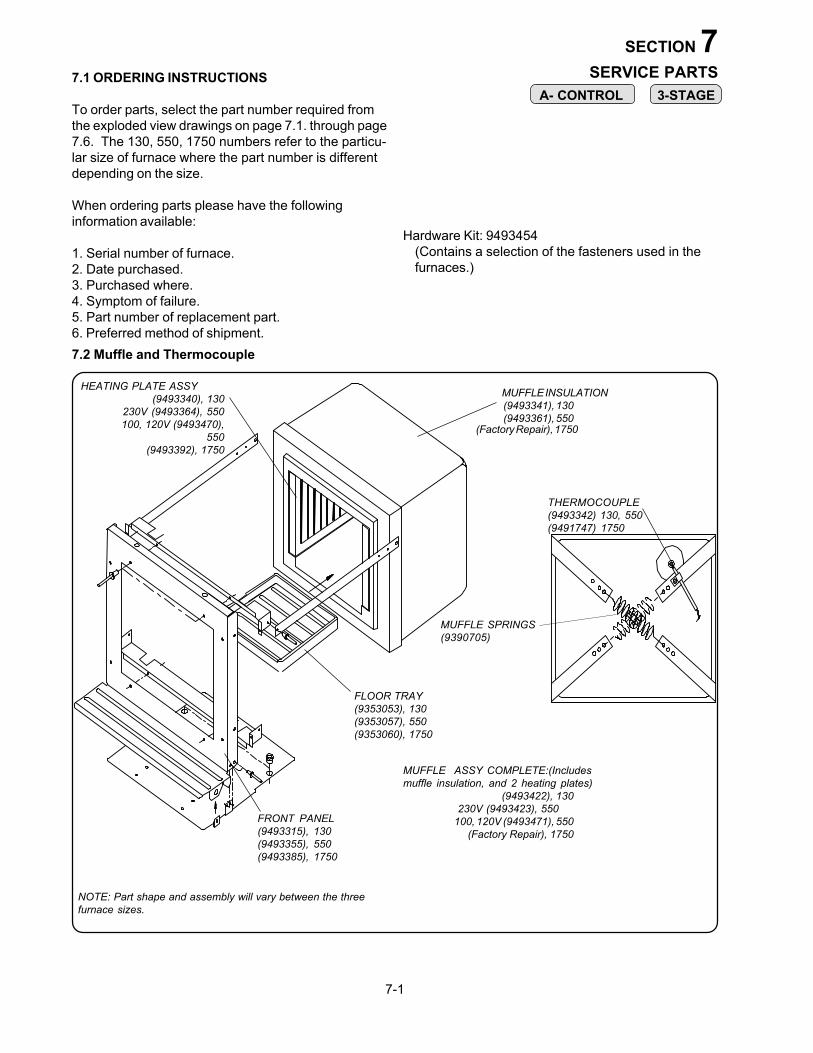
MUFFLE INSULATION (9493341), 130 (9493361), 550
HEATING PLATE ASSY (9493340), 130230V (9493364), 550
100, 120V (9493470),550
(9493392), 1750
FLOOR TRAY(9353053), 130(9353057), 550(9353060), 1750
FRONT PANEL(9493315), 130(9493355), 550(9493385), 1750
THERMOCOUPLE(9493342) 130, 550(9491747) 1750
NOTE: Part shape and assembly will vary between the threefurnace sizes.
MUFFLE ASSY COMPLETE:(Includesmuffle insulation, and 2 heating plates)
(9493422), 130 230V (9493423), 550 100, 120V (9493471), 550 (Factory Repair), 1750
7.1 ORDERING INSTRUCTIONS
To order parts, select the part number required fromthe exploded view drawings on page 7.1. through page7.6. The 130, 550, 1750 numbers refer to the particu-lar size of furnace where the part number is differentdepending on the size.
When ordering parts please have the followinginformation available:
1. Serial number of furnace.2. Date purchased.3. Purchased where.4. Symptom of failure.5. Part number of replacement part.6. Preferred method of shipment.
Hardware Kit: 9493454(Contains a selection of the fasteners used in thefurnaces.)
7.2 Muffle and Thermocouple
A- CONTROL 3-STAGE
(Factory Repair), 1750
MUFFLE SPRINGS(9390705)

3-550 PD
MUFFLE INSULATION (9493780), 550 PDHEATING PLATE ASSY
230V (9493364), 550 PD 100, 120V (9493470), 550 PD
FRONT PANEL(9493808), 550 PD
THERMOCOUPLE(9493342) 550 PD
MUFFLE ASSY COMPLETE:(Includesmuffle insulation, and 2 heating plates)
230V (9493778), 550 PD100, 120V (9493779), 550 PD(9493996), 550A(Factory Repair), 1750A
FLOOR TRAY(9353057), 550
7-2
7.3 Muffle (3-550 PD & AIR EXCH) 3-550A

CABINET ASSY(9493320) 130 FURNACES(9493354) 550 FURNACES(9493384) 1750 FURNACES(9493807) 3-550 PD FURNACE
7.4 Cabinet Parts
(9493338) DOORSAFETY SWITCH
A- CONTROL 3-STAGE
(9493534) REAR PANEL3-550PD FURNACE
3-550 PD
7-3
(9492995) SOCKET ASSY., 200/240V
120V Socket Assy
POWER CORD (120 & 230V)(9390115) 130,550 120V(9309118) 230V US(9309117) 230V EURO(9493653) 1750 EURO(9409131) 1750 US
(9302072) FUSE, 20 amp
(9494462)ADAPTER PLATE, 120V
(9494462) ADAPTER PLATE, 120V
NOTE: To convert to configurations shown, 9495115 - RetrofitKit, is availale for furnaces built prior to S/N 0626xxx.
130, 230V Socket Assy
(9320069) FUSE, 10 amp
(9492996) ADAPTER PLATE, 200/240V
550, 230V Socket Assy
(9311017A) FUSE HOLDER
(9495099)ADAPTER PLATE, 200/240V
(9495104) SOCKET ASSY., 200/240V
(9302072) FUSE, 20 amp
SOCKET ASSY.LOCATION
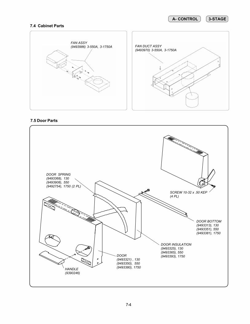
DOOR(9493321) , 130(9493350), 550(9493380), 1750HANDLE
(9390246)
DOOR INSULATION(9493325), 130(9493365), 550(9493393), 1750
DOOR BOTTOM(9493313), 130(9493351), 550(9493381), 1750
SCREW 10-32 x .50 KEP(4 PL)
7.5 Door Parts
7-4
DOOR SPRING(9493368), 130(9493908), 550(9492754), 1750 (2 PL)
A- CONTROL 3-STAGE
FAN ASSY(9493986) 3-550A, 3-1750A FAN DUCT ASSY
(9493970) 3-550A, 3-1750A
7.4 Cabinet Parts

7.6 A- Controller Parts
7-5
OVERLAY(9354229) A-130(9354230) A-550(9354231) A-1750
POWER SWITCH(9306038)
CONTROL DRAWER(9493316) A-130(9493356) A-550(9493386) A-1750
TRIAC(9303015)
HEATSINK
SCREW, 6-32 x .375
KNOB, SET POINT(9355026)
PYROMETER(9390451)
FUSE (20A) - S/N 9525 and 9320072 earlierCONTROL PCB
(R9493348) 100-120V A-130(R9493449) 200-240V A-130(R9493349) 100-120V A-550(R9493450) 200-240V A-550(R9493451) 200-240V A-1750
RELAY, (1750 ONLY)(9320075)
A- CONTROL

7.7 3-Stage Controller Parts
7-6
SCREW, 6-32 x 1.75
SCREW, 6-32 x .375
TC WIRES
TERMINAL BLOCK(9390487)
TRIAC(9303015)
HEATSINK
CONTROL DRAWER(9493376, 3-130)(9493379, 3-550)(9493387, 3-1750)
POWER SWITCH(9306038)
MEMBRANE SWITCH(9494063, 3-550A, 3-1750A)
DISPLAY PCB(R9493347)
FUSE (1A)9320071
3-STAGE & 3-550 PD
CONTROL PCB, 3-550 PD,A(R9493446) 100-125V(R9493447) 200-240V

7.8 Lift Mechanism Parts
MOTOR POWER DOOR(9493777)
BRACKET, MOTOR LINKAGE(9493532)
BRACKET, MOTOR(9493362)
BOLT, SHOULDER .375
SCREW #8 X.375
SCREW, #8-32 SEM
SCREW, 10-32 SEM
BRACE(9493363)PIVOT ARM
NUT, 1/4-20 HEX
SCREW, 1/4-20SPRING(9356016)
LNUT 1/4-20 HEX NYLOK
BRACKET, SPRING
SCREW, #8 X .50
7-7
3-550 PD

SECTION 8DISASSEMBLY/REASSEMBLY
8-1
Tols
8.1.1: Remove 2 screws from bottom front of thefurnace
8.2 TRIAC
Tools: Phillips #2 screwdriver1/4" nut driverneedle nose pliers
8.1 CONTROL DRAWER REMOVAL
8.1.2: Slide control drawer towards you. Note: A bladed screwdriver may be needed to start.
Insert screwdriver if needed
4"
8.2.3: Remove 2 nuts and lift triac off heatsink.
8.2.4: Replace with new triac and note orientation.
8.2.5: Connect wires to triac according to WiringDiagram 2.9 (A Control) or 5.9 (3 Stage)Make sure connections are tight
8.2.2: Disconnect wires from triac located at the rearcenter of the control drawer.(use pliers toassist)
8.2.1: Follow steps 8.1.1 through 8.1.2 of CONTROLDRAWER REMOVAL
- To gain access to the electrical components andmost other service jobs, removal of the controldrawer is required.
Tools: Phillips #2 screwdriver
Use Heatsink (white)compound from old triac.
WARNING:Disconnect power cord from wall outletbefore attempting to service the furnace.

Tools: Phillips screwdriver Knife of other sharp edged device
8.3.1: Follow steps 8.1.1 through 8.1.2 ofCONTROL DRAWER REMOVAL.
8.3.2: Disconnect ribbon cable at control PCB.
8.3 MEMBRANE SWITCH
8-2
8.3.6: Connect ribbon connector
8.3.3: Peel off membrane switch (Use knife if needed).
8.3.4: Clean front panel surface with isopropylalcohol. Allow to dry thoroughly.
8.3.5: Place the new membrane switch by locatingthe bottom edge against the bottom of therecess.
DOT
3-STAGE

Tools: Phillips screwdriver
CAUTION!Use proper ESD grounding techniques whenhandling electronic components
8.4.1: Follow steps 8.1.1 through 8.1.2 ofCONTROL DRAWER REMOVAL
8.4.2: Disconnect grey ribbon connector.
8.4.4: Replace with new Display PCB.
8.4.3: Remove from snap-on standoffs.
8-3
3-STAGE
8.4 DISPLAY PCB
8.4.5: Connect grey ribbon connector. Bend awayfrom Display PCB so it won't cut into ribbon.

Tools: Phillips screwdriverNeedle nose pliers3/8" nut driver or wrench1/4" nut driver13 mm nut driver or pliers
CAUTION!Use proper ESD grounding techniqueswhen handling electronic components
8.5.1: Follow steps 8.1.1 through 8.1.2 of CONTROLDRAWER REMOVAL.
8-4
8.5 A-CONTROL PCB
A-CONTROL
8.5.3: Disconnect orange wire from triac.
8.5.4: Disconnect wires from pyrometer.
PYROMETER
8.5.2: Disconnect wires AC1, AC2, MT1, MT2 and4 muffle wires from power board.
AC1 MT2
AC2
MT1
muffle wires
Orange 8.5.6: Remove 2 screws.
Remove
Reverse steps for reassembly.
8.5.5: Remove knob by pulling out and nut (13mmnut driver or pliers).
CAUTION! Do not overtighten nut

8-5
5
8.6.8: Squeeze plastic standoff and liftcircuit board.
8.6.7: Remove 5 screws.
8.6.6: Remove thermocouple wires
3 STAGE
8.6 3 STAGE CONTROL PCB
DOT
8.6.2: Disconnect wires from power switch.
8.6.1: Follow steps 8.1.1 through 8.1.2 of CON-TROL DRAWER REMOVAL.
Tools: Phillips screwdriverSlotted screwdriverNeedle nose pliers
CAUTION!Use proper ESD grounding techniqueswhen handling electronic components
8.6.3: Disconnect ribbon connectors.
8.6.4: Remove relay and door switch wires.
58.6.9: Replace with new circuit board. Tighten5 screws. Follow wiring diagram 5.9 onpage 5-12. 8.6.5: Disconnect wires from triac.

8.7.4: If door or door insulation needs replacement,remove the 4 screws on bottom of door (step 5.7.2)and slide from slide out assy.
8.7 DOOR ASSEMBLY/ ADJUSTMENT
Tools: 5/32 Allen wrenchPhillips head screwdriver
If the door feels too stiff or too loose when lifting up anddown, a tension adjustment can be made from the outside
8.7.1: If door tension is too loose tighten the screw on eachside until the desired tension is reached. If too tight,loosen screw.
8.7.2: If door insulation is rubbing against cabinet, loosen the 2 screws on each side of door.
8.7.3: Rotate door out from cabinet and tighten 4 screws.Check to make sure that rope contacts muffle lipwhen closed and insulation clears cabinet whenlifted.
8.7.5: Remove 2 screws and slide out door insulation andspring. If door is to be replaced, remove 2 screwsholding handle.
8-6
8.7.6: Replace with new insulation or door by reversingsteps 8.7.4 - 8.7.5.
8.7.7: Set spacing as described in section 8.7.3.Important! Screws must be torqued to 25-30in-lbs.

8-7
Tools: Phillips head screwdriversmall putty knife
Note: Like the headlights on a car, if one heating plateburns out, the other will likely burn out soon. There-fore, it would be advisable to replace both plates atonce.
8.8.3: Pull out bad plate(s) (Rotate bottom of platetoward center of muffle). Be careful whenpulling leads thru holes in muffle.
feed wires thru bushings (one wire per bushing)
8.8.4: Replace with new plate(s). There are brassbushings located in the heatshield below themuffle holes. Cut tie wraps located on termi-nals' insulation. Slide the piece of insulatingsleeve (provided) over the existing ones and tiewrap at 1" below the heat shield. It may takea few attempts to locate this hole with themuffle terminal
rotate in
8.8.5: Optional: a syringe of ceramic adhesive is pro-vided to hold plates secure to sides. Stuffnewspaper in muffle until adhesive sets (1hr). There will be some movement of theplates without the adhesive.
Apply white adhesive(optional)
8.8.6: Connect muffle wires from plate(s) to controlPCB. Refer to wiring diagram 2.9 for A-Control or 5.10 for 3 stage control. (See step8.8.2)
8.8.7: Install floor tray
8.8.8: Install control drawer by reversing steps 8.1.1 -8.8.2
Brake bond withputty knife
8.8 HEATING PLATES
(130, 550) 100, 120V MUFFLE WIRING(1750), 230V
TAN
P1
P1 P6
(130, 550) 230VMUFFLE WIRING
TAN W/BLK MARK
3-STAGE
8.8.1: Disconnect muffle wires from plate(s) to bereplaced. (refer to wiring diagram 2.9 for A-Control and 5.9 for 3-stage control.)
(130, 550) 100, 120V HOOKUP (1750) 230V
(130, 550)230V HOOK UP
A-CONTROL
WARNING:Disconnect power from the wall outlet beforeattempting to service the furnace!
8.8.1: Follow steps 8.1.1 - 8.1.2 of CONTROLDRAWER REMOVAL.
Black markedlead
Black marked lead
8.8.2: Remove floor tray
P6

Tools: Phillips head screwdriver; small flat headscrewdriver; needle nose pliers
8-8
8.9.5: Remove two screws (one each side)
REMOVE SCREWS
8.9.6: Pull/pry out muffle assy (with attached frontpanel) from wraparound
8.9.7: Remove screw used to secure thermocoupleand pull thermocouple from muffle
Remove screw
8.9.8: Remove muffle retaining springs with needlenose pliers. CAUTION: WEAR GLOVESAND EYE PROTECTION!
Remove springs
8.9.9:Remove muffle assy
muffle wires must pass thrubrass bushings (4 pl)
8.9.10: Replace with new muffle assy by reversingsteps 8.9.1 - 8.9.9. Make sure that mufflewires pass thru brass bushings in heatshield
8.9 COMPLETE MUFFLE REPLACEMENT
8.9.4: Open door
8.9.3: Remove 5 or 6 screws on the front top of thefurnace. Remove exhaust port
REMOVE SCREWS
TAN W/BLK MARK
230V MUFFLE WIRING
TAN
P1
230V HOOK UP
P1 P6
8.9.2: Disconnect muffle wires. (Refer to wiringdiagram 2.9 for A-Control and 5.9 for threestage control.)
100, 120VMUFFLEWIRING
TANTAN W/BLK MARK
100, 120V HOOKUP
A-CONTROL
3 - Stage
8.9.1: Follow steps 8.1.1 - 8.1.2 of CONTROLDRAWER REMOVAL.
WARNING:Disconnect power from the wall outlet beforeattempting to service the furnace!

8-9
8.9.12: Check muffle resistance to verify wiring iscorrect before securing control drawer:
8.10.3: Disconnect thermocouple from pyrometer
8.10.4: Remove nut. Replace thermocouple by revers-ing previous steps and replace nut.
red yel
red RED1
RED1 yelYEL1
remove and replace nut
meter
PYROMETER
8.11 THERMOCOUPLE (3 Stage Control)Tools: bladed screwdriver
phillips head screwdriver1/4" nutdriver
Tools: bladed screwdriver phillips head screwdriver, 3/8" nutdriver, wrench, 1/4" nutdriver
WARNING:Disconnect power from the wall outletbefore attempting to service the furnace!
8.10.1: Follow steps 8.1.1 - 8.1.2 of control drawerremoval
8.10.2: Follow steps 8.9.3 - 8.9.7 from previous pagefor muffle replacement for furnaces without arear access panel. Note: All 1750 furnaces andall furnaces with S/N date codes after 9701 willhave rear access panel so that muffle will notneed to be removed to service thermocouple(see step 8.11.6 for details).
bracket
8.9.11: Front panel must insert into offset bracket inwraparound
100v 120v 200-240vA-130, 3-130 8 ohms 8 ohm 32 ohmsA-550, 3-550 8 ohms 8 ohms 24 ohmsA-1750, 3-1750 12 ohms
8.10 THERMOCOUPLE (A-Control)
8.11.1: Follow steps 8.1.1 - 8.1.2 of control drawerremoval
8.11.3: Remove nut which holds thermocouple tocontrol drawer.
remove nut
8.11.4: Disconnect thermocouple from circuit board
8.11.5: Replace with new thermocouple by reversingprevious steps 8.11.1 thru 8.11.4
RED YEL
RED YEL
8.11.2: Follow steps 8.9.3 - 8.9.7 from previous pagefor muffle replacement for furnaces without arear access panel. Note: All 1750 furnaces andall furnaces with S/N date codes after 9701 willhave rear access panel so that muffle will notneed to be removed to service thermocouple(see step 8.11.6 for details).
WARNING:Disconnect power from the wall outletbefore attempting to service the furnace!

Tools: Phillips head screwdriver; bladed screw driver; needle nose pliers
REMOVE SCREWS
8.12.7: Remove screw used to secure thermocoupleand pull thermocouple from muffle
Remove screw
8.12.8: Remove muffle assy by removing 10 screw.
muffle wires must pass thrubrass bushings (4 pl)
8.12.9: Replace with new muffle assy by reversingsteps 8.12.1 - 8.12.8. Make sure that mufflewires pass thru brass bushings in heatshield
8.12 COMPLETE MUFFLE REPLACEMENT
8.12.2: Close door and remove 6 screws on the fronttop of the furnace. Remove exhaust port
REMOVE SCREWS
TAN W/BLK MARK
230V MUFFLE WIRING
8.12.4: Disconnect muffle wires. (Refer to wiringdiagram 5.9).
100, 120VMUFFLEWIRING
TANTAN W/BLK MARK
8.12.1: Follow steps 8.1.1 - 8.1.2 of CONTROLDRAWER REMOVAL.
WARNING:Disconnect power from the wall outlet beforeattempting to service the furnace!
8.12.5: Disconnect thermocouple from circuit board
RED YEL
RED YEL
8.12.6: Pull/pry out muffle assy (with attached frontpanel) from wraparound
8.12.3: Close door and remove six screws ( threeeach side)
8-10
(3-550 PD)

8.12.11: Check muffle resistance to verify wiring iscorrect before securing control drawer:
8.13 THERMOCOUPLE (3-550 PD)Tools: bladed screwdriver
phillips head screwdriver 1/4" nutdriver bracket
8.12.10: Front panel must insert into offset bracketin wraparound
100v 120v 200-240v3-550 PD 8 ohms 8 ohms 24 ohms
8.13.1: Follow steps 8.1.1 - 8.1.2 of control drawerremoval
8.13.2: Remove nut which holds thermocouple tocontrol drawer.
remove nut
8.13.3: Disconnect thermocouple from circuit board
RED YEL
RED YEL
WARNING:Disconnect power from the wall outletbefore attempting to service the furnace!
8-11

8-12
8.14.2: Disconnect switch wires
8.14 POWER SWITCH
Tools: Slotted screwdriver
8.14.1: Follow steps 8.1.1 through 8.1.2 ofCONTROL DRAWER REMOVAL
8.14.4: Press in new switch
8.14.5: Connect switch wires
8.14.3: Remove switch by pressing in tabs.
8.13.5: Replace with new thermocouple by reversingprevious steps 8.11.1 thru 8.11.4
8.13.4: Remove screw used to secure thermocoupleand pull thermocouple from muffle. Pullthermocouple wire through brass grommet.
8.13.3: Remove the 2 screws which support rear panel.
Remove 2 screws
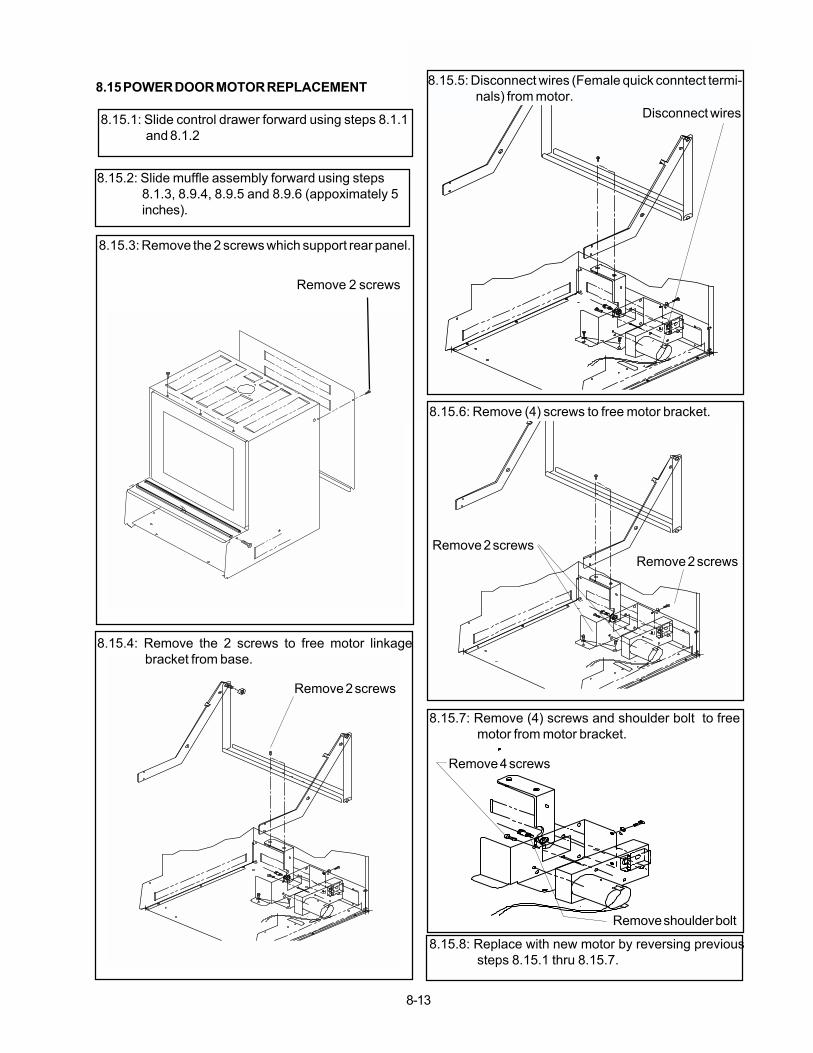
8.15 POWER DOOR MOTOR REPLACEMENT
8-13
8.15.1: Slide control drawer forward using steps 8.1.1and 8.1.2
8.15.2: Slide muffle assembly forward using steps8.1.3, 8.9.4, 8.9.5 and 8.9.6 (appoximately 5inches).
8.15.3: Remove the 2 screws which support rear panel.
Remove 2 screws
8.15.4: Remove the 2 screws to free motor linkagebracket from base.
Remove 2 screws
Disconnect wires
8.15.7: Remove (4) screws and shoulder bolt to freemotor from motor bracket.
Remove 4 screws
Remove shoulder bolt
8.15.8: Replace with new motor by reversing previoussteps 8.15.1 thru 8.15.7.
Remove 2 screwsRemove 2 screws
8.15.5: Disconnect wires (Female quick conntect termi-nals) from motor.
8.15.6: Remove (4) screws to free motor bracket.

VULCAN FURNACE SERVICE NOTES:
$7.95 BOXIII 0640 93-63-049