Embed Size (px)
Citation preview

CommerCial / residential gas water heater
service handbook
PRINTED IN THE U.S.A. 0410 318556-000
serviCing should only be performed by a Qualified serviCe agent
500 Tennessee Waltz ParkwayAshland City, TN 37015
for models:btX 100, gdhe 50series 120 & 121
installation Considerations - pre serviCeCheCKs - water heater ConstruCtion -
operation & serviCe - troubleshooting


1
table of ContentsTAblE Of CONTENTS .......................................................................... 1INTRODUCTION .................................................................................... 2
Qualifications ..................................................................................... 2Service Warning ................................................................................ 2Service Reminder .............................................................................. 2Tools Required ................................................................................... 2
INSTAllATION CONSIDERATIONS ..................................................... 3Instruction Manual ............................................................................. 3Closed Water Systems ...................................................................... 3Thermal Expansion ............................................................................ 3Air Requirements ............................................................................... 3Contaminated Air ............................................................................... 3Venting ............................................................................................... 4
General Venting Information ....................................................... 4Maximum Equivalent Length Requirements ............................... 4Intake Air Connection .................................................................. 5
Electrical Requirements ..................................................................... 6Grounding and Polarity ............................................................... 6Power Supply Test ...................................................................... 6
Installation Check List ........................................................................ 7FEATuRES And CoMPonEnTS ......................................................... 8
Front & Back Views ........................................................................... 8Top View ............................................................................................ 9Combustion Blower & Burner Assembly ............................................ 9
OPERATION AND SERvICE ............................................................... 10How It Works ................................................................................... 10Combustion Blower ..........................................................................11Burner Assembly ............................................................................. 12Combustion Blower and Burner Removal ....................................... 14Flame Sensor .................................................................................. 18
Flame Sensing operation ......................................................... 18Flame Sensing Current Test ...................................................... 19
Igniter ............................................................................................... 20Igniter Current Test .................................................................... 20
venturi ............................................................................................. 22Gas valve ........................................................................................ 23
Gas Valve Voltage Tests............................................................ 23Gas Valve Removal ................................................................... 24
Gas Pressure ................................................................................... 25Gas Pressure Test ..................................................................... 26Gas Flow Test ........................................................................... 27
Pressure Switches ........................................................................... 28Construction & operation .......................................................... 28Control System Monitoring ........................................................ 29
Pressure Switch Tests ..................................................................... 31Continuity Test during Standby ................................................. 31Continuity Test during operation .............................................. 32Pressure Test during operation ................................................ 32
Temperature Probe .......................................................................... 35Temperature Sensor Test .......................................................... 35ECo Continuity Test .................................................................. 36
Control System Hardware ......................................................... 37uIM (user Interface Module) ............................................... 37CCB (Central Control Board) .............................................. 39CCB Cover Removal And Replacement ............................. 40CCB Circuit Board Layout ................................................... 41CCB Connection Identification ........................................... 42
Wiring diagram .......................................................................... 44ConTRoL SySTEM oPERATIon ................................................ 45
Overview .................................................................................... 45Control System Features .................................................... 45Commercial And Residential Models .................................. 46Control System navigation .................................................. 46user Input Buttons .............................................................. 46desktop Screen ................................................................... 46Status Icons ........................................................................ 47operating States ................................................................. 48
Control System Menus .............................................................. 48Temperatures ...................................................................... 49Heater Status ...................................................................... 50display Settings .................................................................. 51Heater Information .............................................................. 51Current fault ....................................................................... 52Fault History ........................................................................ 52Fault occurrence ................................................................. 52Restore Factory defaults .................................................... 52Service Contact Information ................................................ 53
Sequence of operation ............................................................. 54Sequence of operation Flow Chart .......................................... 55
TROUblESHOOTING ................................................................... 56Rough Starting/Rough operation ........................................ 56not Enough Hot Water ........................................................ 56Heater Status Menu ............................................................ 56Things To Check Before Servicing ...................................... 56Resetting The Control System ............................................ 56
Control System unresponsive ................................................... 57uIM (LCd) Is Blank ............................................................. 57uIM Is Inoperable ................................................................ 57
Fault Messages ......................................................................... 58AC Reversed ....................................................................... 58Temp Probe open ............................................................... 58Temp Probe Short ............................................................... 58Flame Sensor Short ............................................................ 59Flame detect Error .............................................................. 59Energy Cut out (ECo) ........................................................ 60Blocked Air Intake ............................................................... 61Blocked Exhaust ................................................................. 62Blower Prover Failure .......................................................... 62Blower Prover open ............................................................ 63Low Igniter Current .............................................................. 64Ignition Failure ..................................................................... 65Communication Failure ....................................................... 66

2 Servicing should only be performed by a Qualified Service Agent
This Service Manual covers the water heater Model and Series numbers listed on the front cover only. The instructions and illustrations contained in this manual will provide you with troubleshooting procedures to verify proper operation and diagnose and repair common service problems.
QualifiCationsQualified installer or serviCe agenCyInstallation and service of this water heater requires ability equivalent to that of a Qualified Agency (as defined by AnSI below) in the field involved. Installation skills such as plumbing, air supply, venting, gas supply and electrical supply are required in addition to electrical testing skills when performing service.ansi Z223.1 2006 sec. 3.3.83: “Qualified Agency” - “Any individual, firm, corporation or company that either in person or through a representative is engaged in and is responsible for (a) the installation, testing or replacement of gas piping or (b) the connection, installation, testing, repair or servicing of appliances and equipment; that is experienced in such work; that is familiar with all precautions required; and that has complied with all the requirements of the authority having jurisdiction.”
serviCe warningIf you are not qualified (as defined by AnSI above) and licensed or certified as required by the authority having jurisdiction to perform a given task do not attempt to perform any of the procedures described in this manual. If you do not understand the instructions given in this manual do not attempt to perform any procedures outlined in this manual.
serviCe reminderWhen performing any troubleshooting step outlined in this manual always consider the wiring and connectors between components. Perform a close visual inspection of all wiring and connectors to and from a given component before replacement. Ensure wires were stripped before being crimped in a wire connector, ensure wires are crimped tightly in their connectors, ensure connection pins in sockets and plugs are not damaged or worn, ensure plugs and sockets are mating properly and providing good contact.Failure to perform this critical step or failing to perform this step thoroughly often results in needless down time, unnecessary parts replacement, and customer dissatisfaction.
tools reQuired• Instruction Manual that came with the water heater.• All tools common to installation and service of commercial water heaters such as hand tools, torch, pipe
wrenches etc.• Long (8-10”) T handle 1/8 inch hex (allen key) wrench for Combustion Blower removal and installation.• Hex (Allen) wrench sizes: 5/32”, 1/8”, 1/4” and 5/16" - for Burner, and 24 Volt Gas Valve removal and
installation.• Two digital manometers: Range -20.00 to +20.00" W.C. Resolution - 0.01" W.C. Recommend uEI model
EM200 or equivalent. Required to test pressure switch performance. Also used to measure supply and manifold gas pressures.
• digital Multi Meter; Fieldpiece HS36, Fluke 187, uEI dL289 or equivalent capable of measuring:• AC/dC Voltage.• ohms.• dC micro amps (μA) - flame sensing current, see Flame Sensing Current Test on page 19.
• AC amp meter- recommend uEI model dL289 or equivalent.• 120 VAC plug in outlet tester, see Figure 2 on page 6
introduCtion

3Servicing should only be performed by a Qualified Service Agent
installation ConsiderationsThis section of the Service Manual covers some of the critical installation requirements that, when overlooked, often result in operational problems, down time and needless parts replacement. Costs to correct installation errors are not covered under the limited warranty. Ensure all installation requirements and instructions contained in the Instruction Manual that came with the water heater have been followed prior to performing any service procedures.
instruCtion manualHave a copy of the Instruction Manual that came with the water heater on hand for the model and series number being serviced. Installation information given in this Service Manual is not a complete installation instruction. Installation information given in this manual has a limited focus as it applies to servicing the water heater. This Service Manual does not replace or supersede the Instruction Manual that came with the water heater. Always refer to the Instruction Manual for complete installation instructions. If the Instruction Manual is not on hand copies can be obtained from the manufacturers web site or by calling the technical support phone number shown on the back cover of this manual.
Closed water systemsWater supply systems may, because of code requirements or such conditions as high line pressure, among others, have installed devices such as pressure reducing valves, check valves, and back flow preventers. devices such as these cause the water system to be a closed system.
thermal eXpansionAs water is heated, it expands (thermal expansion). In a closed system the volume of water will grow when it is heated. As the volume of water grows there will be a corresponding increase in water pressure due to thermal expansion. Thermal expansion can cause premature tank failure (leakage). This type of failure is not covered under the limited warranty. Thermal expansion can also cause intermittent Temperature-Pressure Relief Valve operation: water discharged from the valve due to excessive pressure build up. This condition is not covered under the limited warranty. The Temperature-Pressure Relief Valve is not intended for the constant relief of thermal expansion.A properly sized thermal expansion tank must be installed on all closed systems to control the harmful effects of thermal expansion. Contact a local plumbing service agency to have a thermal expansion tank installed.
air reQuirementsCarefully review the requirements for combustion and ventilation air in the Instruction Manual that came with the water heater. Failure to meet these requirements when the water heater is installed or overlooking their importance when servicing the water heater often results in needless down time, unnecessary parts replacement, and customer dissatisfaction.An inadequate supply of air for combustion and ventilation often causes operational problems. A lack of combustion and ventilation air can create a negative ambient air pressure in the installed space which can lead to improper combustion and operational problems with pressure switches.
Contaminated airCombustion air that is contaminated can greatly diminish the life span of the water heater and water heater components such as Igniters and Burners. Propellants of aerosol sprays, beauty shop supplies, water softener chemicals and chemicals used in dry cleaning processes that are present in the combustion, ventilation or ambient air can cause such damage.Vapors from volatile compounds such as solvents, cleaners, chlorine based chemicals and refrigerants in addition to being highly flammable in many cases, can also react to form highly corrosive substances such as hydrochloric acid inside the combustion chamber. The results can be hazardous and cause product failure.If the water heater is installed in beauty shops, barber shops or laundries with dry cleaning equipment, it is imperative the water heater be installed in a direct Vent configuration so that air for combustion is derived directly from the outdoor atmosphere through a sealed intake air pipe. See the venting installation section in the Instruction Manual that came with the water heater for more information on direct Vent installations.

4 Servicing should only be performed by a Qualified Service Agent
ventingThis section of the Service Manual is not a complete venting installation instruction. Refer to the Instruction Manual that came with the water heater; ensure the venting has been installed per all Instruction Manual requirements. Costs to correct installation errors are not covered under the limited warranty.general venting informationThe water heaters covered in this manual are operationally equivalent to Category IV appliances and may be installed in either a Power Vent or direct Vent configuration.Category iv applianceCategory IV appliances operate with a positive vent (exhaust) static pressure and with vent gas temperatures low enough to produce condensate in the vent piping.Power Vent ConfigurationPower Vent configurations derive all combustion air from the room where they are installed and discharge all flue gases to the outdoor atmosphere through a sealed vent (exhaust) pipe. Power vent configurations have one vent pipe connected to the water heater which can be terminated in a vertical or horizontal arrangement.Direct Vent Configurationdirect Vent configurations derive all combustion air directly from the outdoor atmosphere through a sealed intake air pipe and discharge all flue gases to the outdoor atmosphere through a sealed vent (exhaust) pipe. direct Vent configurations have two pipes connected to the water heater, one vent pipe and one intake air pipe. direct Vent configurations can also be terminated in a vertical or horizontal arrangement.maXimum eQuivalent length reQuirements
The the intake air and/or vent pipe for the water heaters covered in this manual can be installed using 2 inch or 3 inch pipe depending on the overall “equivalent length" of each pipe. Equivalent lengths are calculated by adding the total linear feet of installed pipe to the accumulated equivalent length of all field installed elbows.Each 2 inch or 3 inch 90° elbow installed is equivalent to 5 linear feet of pipe. 45° elbows are equivalent to 2.5 linear feet of pipe.
on direct Vent installations the intake air and/or vent pipe are calculated separately and each pipe's total equivalent length must not exceed the maximum equivalent length requirements stated in the Instruction Manual that came with the water heater, see Table 1 below.table 1†Number of 90° Elbows Installed
2 inch pipe 3 inch pipeMaximum Feet (Meters) Maximum Feet (Meters)
one (1) 40 feet (12.2 meters) 120 feet (36.6 meters)Two (1) 35 feet (10.7 meters) 115 feet (35.0 meters)Three (3) 30 feet (9.1 meters) 110 feet (33.5 meters)Four (4) 25 feet (7.6 meters) 105 feet (32.0 meters)Five (5) 20 feet (6.1 meters) 100 feet (30.5 meters)Six (6) 15 feet (4.6 meters) 95 feet (29.0 meters)† Two 45° elbows are equivalent to one 90° elbow.
pipe siZe reQuirementsEnsure the correct size pipe has been used for the length of intake air and/or vent piping installed. 2 inch pipe may be used up to 40 equivalent feet with one 90° elbow installed, if the installation requires more equivalent feet of intake air and/or vent pipe, 3 inch pipe must be used up to the maximum shown in Table 1 above.maXimum elbow reQuirementsThe maximum number of 90° elbows allowed for the vent pipe is six (6). on direct Vent installations the maximum number of 90° elbows allowed for the intake air pipe is six (6), see Table 1 above.
2”
3”
= 5 linear feet of pipe
= 5 linear feet of pipe
5Servicing should only be performed by a Qualified Service Agent
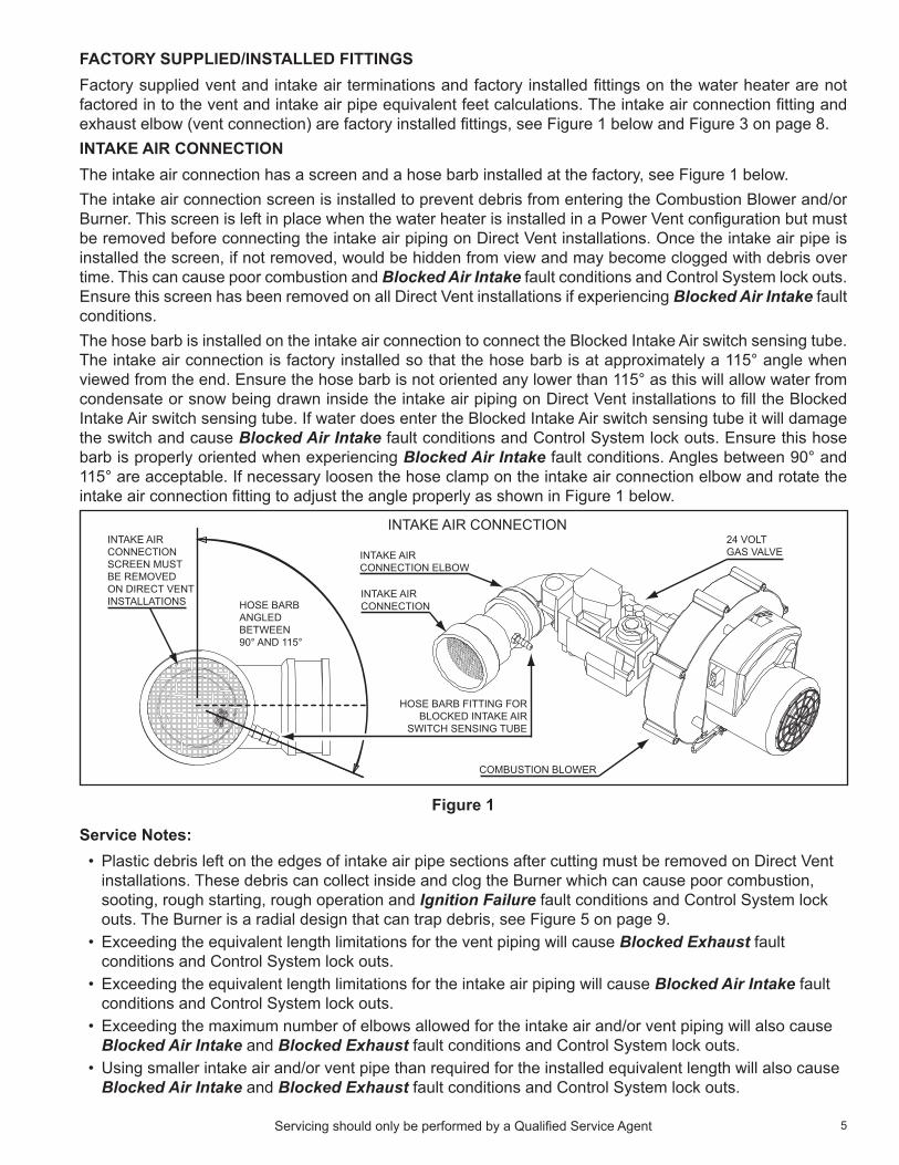
faCtory supplied/installed fittingsFactory supplied vent and intake air terminations and factory installed fittings on the water heater are not factored in to the vent and intake air pipe equivalent feet calculations. The intake air connection fitting and exhaust elbow (vent connection) are factory installed fittings, see Figure 1 below and Figure 3 on page 8.intaKe air ConneCtionThe intake air connection has a screen and a hose barb installed at the factory, see Figure 1 below.The intake air connection screen is installed to prevent debris from entering the Combustion Blower and/or Burner. This screen is left in place when the water heater is installed in a Power Vent configuration but must be removed before connecting the intake air piping on direct Vent installations. once the intake air pipe is installed the screen, if not removed, would be hidden from view and may become clogged with debris over time. This can cause poor combustion and Blocked Air Intake fault conditions and Control System lock outs. Ensure this screen has been removed on all direct Vent installations if experiencing Blocked Air Intake fault conditions.The hose barb is installed on the intake air connection to connect the Blocked Intake Air switch sensing tube. The intake air connection is factory installed so that the hose barb is at approximately a 115° angle when viewed from the end. Ensure the hose barb is not oriented any lower than 115° as this will allow water from condensate or snow being drawn inside the intake air piping on direct Vent installations to fill the Blocked Intake Air switch sensing tube. If water does enter the Blocked Intake Air switch sensing tube it will damage the switch and cause Blocked Air Intake fault conditions and Control System lock outs. Ensure this hose barb is properly oriented when experiencing Blocked Air Intake fault conditions. Angles between 90° and 115° are acceptable. If necessary loosen the hose clamp on the intake air connection elbow and rotate the intake air connection fitting to adjust the angle properly as shown in Figure 1 below.
HOSE BARBANGLEDBETWEEN90° AND 115°
HOSE BARB FITTING FORBLOCKED INTAKE AIR
SWITCH SENSING TUBE
COMBUSTION BLOWER
INTAKE AIR CONNECTION24 VOLTGAS VALVE
INTAKE AIRCONNECTION
INTAKE AIRCONNECTION ELBOW
INTAKE AIRCONNECTIONSCREEN MUSTBE REMOVEDON DIRECT VENTINSTALLATIONS
Figure 1
Service Notes:• Plastic debris left on the edges of intake air pipe sections after cutting must be removed on direct Vent
installations. These debris can collect inside and clog the Burner which can cause poor combustion, sooting, rough starting, rough operation and Ignition Failure fault conditions and Control System lock outs. The Burner is a radial design that can trap debris, see Figure 5 on page 9.
• Exceeding the equivalent length limitations for the vent piping will cause Blocked Exhaust fault conditions and Control System lock outs.
• Exceeding the equivalent length limitations for the intake air piping will cause Blocked Air Intake fault conditions and Control System lock outs.
• Exceeding the maximum number of elbows allowed for the intake air and/or vent piping will also cause Blocked Air Intake and Blocked Exhaust fault conditions and Control System lock outs.
• using smaller intake air and/or vent pipe than required for the installed equivalent length will also cause Blocked Air Intake and Blocked Exhaust fault conditions and Control System lock outs.
6 Servicing should only be performed by a Qualified Service Agent
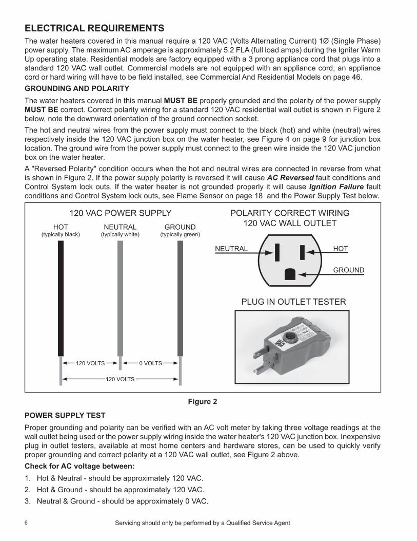
eleCtriCal reQuirementsThe water heaters covered in this manual require a 120 VAC (Volts Alternating Current) 1Ø (Single Phase) power supply. The maximum AC amperage is approximately 5.2 FLA (full load amps) during the Igniter Warm up operating state. Residential models are factory equipped with a 3 prong appliance cord that plugs into a standard 120 VAC wall outlet. Commercial models are not equipped with an appliance cord; an appliance cord or hard wiring will have to be field installed, see Commercial And Residential Models on page 46. grounding and polarityThe water heaters covered in this manual must be properly grounded and the polarity of the power supply must be correct. Correct polarity wiring for a standard 120 VAC residential wall outlet is shown in Figure 2 below, note the downward orientation of the ground connection socket.The hot and neutral wires from the power supply must connect to the black (hot) and white (neutral) wires respectively inside the 120 VAC junction box on the water heater, see Figure 4 on page 9 for junction box location. The ground wire from the power supply must connect to the green wire inside the 120 VAC junction box on the water heater. A "Reversed Polarity" condition occurs when the hot and neutral wires are connected in reverse from what is shown in Figure 2. If the power supply polarity is reversed it will cause AC Reversed fault conditions and Control System lock outs. If the water heater is not grounded properly it will cause Ignition Failure fault conditions and Control System lock outs, see Flame Sensor on page 18 and the Power Supply Test below.
HOT(typically black)
NEUTRAL(typically white)
GROUND(typically green)
120 VOLTS
120 VOLTS
0 VOLTS
120 VAC POWER SUPPLY POLARITY CORRECT WIRING120 VAC WALL OUTLET
PLUG IN OUTLET TESTER
NEUTRAL HOT
GROUND
Figure 2
power supply testProper grounding and polarity can be verified with an AC volt meter by taking three voltage readings at the wall outlet being used or the power supply wiring inside the water heater's 120 VAC junction box. Inexpensive plug in outlet testers, available at most home centers and hardware stores, can be used to quickly verify proper grounding and correct polarity at a 120 VAC wall outlet, see Figure 2 above.Check for AC voltage between:1. Hot & neutral - should be approximately 120 VAC.2. Hot & Ground - should be approximately 120 VAC.3. neutral & Ground - should be approximately 0 VAC.

7Servicing should only be performed by a Qualified Service Agent
installation CheCK listThe list below represents some of the most critical installation requirements that, when overlooked, often result in operational problems, down time and needless parts replacement. Before performing any troubleshooting procedures use the list below to check for installation errors. Costs to correct installation errors are not covered under the limited warranty. Ensure all installation requirements and instructions contained in the Instruction Manual that came with the water heater have been observed and followed.See Troubleshooting on page 56 for service procedures relating to the fault conditions mentioned below.1. The vent (exhaust) pipe must not be combined or connected to any other appliance’s vent system or
chimney.2. The intake air pipe must not be combined or connected to any other appliance’s intake air piping.3. The water heaters covered in this manual are condensing appliances. Condensate will form in the vent
pipe during normal operation, condensate can also form in the intake air piping in certain circumstances. Ensure the intake air and/or vent piping is not installed in a manner that will allow water to be trapped in the piping. This will lead to Blocked Exhaust and/or Blocked Air Intake fault conditions and Control System lock outs.
4. Ensure the intake air and/or vent piping is the correct size for the installed length. See the venting requirements section in the Instruction Manual that came with the water heater. using smaller pipe than is required will lead to Blocked Exhaust and/or Blocked Air Intake fault conditions and Control System lock outs.
5. Ensure the intake air and/or vent piping are within the maximum equivalent lengths required in the Instruction Manual that came with the water heater. Exceeding the maximum length or number of elbows allowed will also lead to Blocked Exhaust and/or Blocked Air Intake fault conditions and Control System lock outs.
6. Ensure there is a water trap formed in the condensate drain tube/line connected to the exhaust elbow on the water heater and that the condensate drain is flowing freely. Condensate drain blockage will cause the exhaust elbow to fill with water and lead to Blocked Exhaust fault conditions and Control System lock outs.
7. Ensure the vent and intake air terminations have adequate clearances from each other and the terminations of other appliances. Failure to maintain adequate clearances can cause the recirculation of flue gases between the vent and intake air piping. Recirculation of flue gases will cause poor combustion, sooting, ignition failure, rough starts, rough operation, premature failure of the heat exchanger and icing of the combustion air intake during severe cold weather.
8. direct vent terminations being installed in dead air spaces such as alleys, atriums, and inside corners can also cause the recirculation of flue gases between the vent and intake air piping. To prevent the recirculation of flue gases, maintain as much distance as possible between the intake air and vent terminations.
9. Ensure the screens in the factory supplied terminations are securely installed to prevent blockage in the intake air and/or vent piping.
10. on direct Vent installations ensure the screen at the intake air connection on the water heater was removed before the intake air piping was connected, see Intake Air Connection on page 5.
11. Ensure the power supply connections to the water heater are polarity correct. use a 120 VAC household outlet tester to verify correct polarity and ground at an outlet the water heater is plugged into. Reversed polarity (neutral and hot wires reversed) will cause the AC Reversed fault condition and Control System lock out.
12. Ensure the water heater and the Burner are properly grounded. The water heater Control System requires an adequate earth ground for flame sensing (verification), see Flame Sensing operation on page 18. Inadequate grounding to the water heater and/or the Burner will cause the Ignition Failure fault condition and Control System lock out. See Electrical Requirements on page 6 and Figure 10 on page 13.

8 Servicing should only be performed by a Qualified Service Agent
features and Componentsfront & baCK views
HEATING LOOPRETURN LINECONNECTION3/4 INCH NPT
DRAIN VALVE
TEMPERATUREPRESSURERELIEF VALVE
FRONT VIEW BACK VIEW
EXHAUST ELBOW(2 INCH PVC VENTCONNECTION)
CONDENSATEDRAIN CONNECTION
BLOCKED EXHAUSTSWITCH SENSING TUBE
HEATING LOOPSUPPLY LINECONNECTION3/4 INCH NPT
2 INCH PVCINTAKE AIRCONNECTION
TOP COVER
ON / OFF SWITCH
UIM(user interface module)
CONTROL INTERFACECOVER.
TEMPERATUREPROBE - LOCATEDBEHIND CONTROLINTERFACE COVER
TANK GLASSINGPLUG COVER.USED FORMANUFACTURINGPURPOSES ONLY.
DO NOT REMOVEGLASSING PLUGFOR ANY SERVICEOR MAINTENANCE.
COVER MAY BEREMOVED IF LEAKIS SUSPECTED.
Figure 3

9Servicing should only be performed by a Qualified Service Agent
top view
BLOWERPROVERSWITCH
CCB ENCLOSURE(central control board)
3/4 INCH NPTWATER OUTLETWITH OUTLETANODE ROD
3/4 INCH NPTWATER INLET
BLOCKEDEXHAUSTSWITCH
TEMPERATUREPRESSURERELIEF VALVE
BURNERSIGHT GLASS
FRONT
1/2 INCHSUPPLY GASCONNECTION
BLOCKEDINTAKE AIRSWITCH
COMBUSTIONBLOWER
2 INCH PVCINTAKE AIRCONNECTION
2 INCH PVCVENT CONNECTION
JUNCTIONBOX - 120 VACPOWER SUPPLYCONNECTIONS
SECONDANODE ROD
Figure 4
Combustion blower & burner assembly
COMBUSTIONBLOWER
EXPLODED VIEW
GASKET(SILICONE)
BLOWERDISCHARGE
ORIFICE
GASKET(FIBER)
BURNER SIGHTGLASS AND
WIRING HARNESSCOVER PLATE
GASKET (SILICONE)
GASKET
GASKET (FIBER)
GASKET (FIBER)
BURNER SIGHT GLASS
BURNERADAPTER
BURNER ADAPTERWIRING HARNESS.IGNITER/FLAMESENSOR
IGNITER
BURNER
BURNER FLANGE(FLOATING FLANGE)
FLAMESENSOR
GAS VALVEVENTURI ASSEMBLY
INTAKE AIRELBOW
ASSEMBLED VIEW
Figure 5

10 Servicing should only be performed by a Qualified Service Agent
OPERATION AND SERvICE
how it worKsThis section of the manual will cover operation, common service procedures and water heater construction. The water heater covered in this manual has a helical shaped coil heat exchanger that is submerged in the storage tank. These water heaters use a top mounted down fired radial design Burner. This is a forced draft burner; hot burning gases are forced through the heat exchanger under pressure and exit through the exhaust/vent connection located at the bottom of the water heater.Starting at the top air and fuel gas are drawn in by the Combustion Blower and Venturi, see Combustion Blower on page 11 and Venturi on page 22. Flue gases and are forced through the helical shaped heat exchanger by the Combustion Blower and out through the exhaust/vent outlet, see Figure 6 below.
BLOWER/BURNERGAS VALVEASSEMBLY
COMBUSTIONAIR INTAKECONNECTION
HELICAL SHAPEHEAT EXCHANGER
ARROWS SHOWPATH OF FLUEGASES THROUGHTHE HEATEXCHANGER
EXHAUST/VENTOUTLET
INTERNAL VIEW
Figure 6

11Servicing should only be performed by a Qualified Service Agent
Combustion blowerThe Combustion Blower is an assembly that includes the blower housing, blower motor and an electronic speed control. The Combustion Blower is controlled by the CCB (Central Control Board), see Control System Hardware on page 37. The CCB sends 120 VAC from the J2 socket on the CCB circuit board to a 3 pin wiring socket on the blower assembly, see CCB Circuit Board Layout on page 41 and Figure 7 below. The CCB also sends a PWM (Pulse Width Modulation) signal from the J13 socket to a 5 pin wiring socket on the assembly. The PWM signal is an electronic instruction to start, stop and control blower speed.The Combustion Blower runs at higher speeds during the Pre/Post Purge operating states and runs at a lower speed during the Igniter Warm up operating state, see Table 6 on page 48 for a list of operating states. The Igniter Status icon is displayed on the Control System LCd during the Igniter Warm up operating state, see Table 5 on page 47.service note: The 5 pin PWM signal plug MuST remain plugged in to the 5 pin socket on the blower assembly at all times. disconnecting this plug will cause the Combustion Blower to run at maximum speed continuously. This may cause rough starts, rough operation and/or the Ignition Failure fault condition and Control System lock out. If the electronic speed control is functioning properly Combustion Blower speed should noticeably reduce during the Igniter Warm up operating state. If blower speed reduction does not occur during the Igniter Warm up operating state ensure the 5 pin plug from the CCB is securely plugged into the matching 5 pin socket on the blower assembly and that the J13 plug is securely plugged into the J13 socket on the CCB circuit board. Perform a close visual inspection of the pins inside the plugs and sockets at the Combustion Blower and the CCB, replace any worn or damaged wiring harnesses as necessary.
BLOWER MOTORAND ELECTRONICSPEED CONTROL
COMBUSTION BLOWER ASSEMBLY
BLOWERHOUSING
3 PINWIRING
SOCKET
5 PINWIRINGSOCKET
Figure 7

12 Servicing should only be performed by a Qualified Service Agent
burner assemblyThe Burner is a radial design burner with a steel fiber jacket on the outer surface and is part of a larger Burner Assembly. Figure 8 and Figure 9 below show side views of the complete Burner Assembly removed from the water heater with key components identified. See the exploded view of the Combustion Blower & Burner Assembly on page 9 also.
BURNER ADAPTERWIRING HARNESSIGNITER/FLAMESENSOR
BLOWERFLANGE
BURNERADAPTER
BURNERFLANGE &GASKET
BURNER
BURNER ASSEMBLYRIGHT SIDE VIEW
FLAMESENSOR
Figure 8
BURNER ADAPTERWIRING HARNESSIGNITER/FLAMESENSOR
BLOWERFLANGE
BURNERADAPTER
BURNERFLANGE &GASKET
BURNER
BURNER ASSEMBLYLEFT SIDE VIEW
IGNITER
Figure 9

13Servicing should only be performed by a Qualified Service Agent
BURNER GROUNDWIRE
BURNERADAPTER
BLOWER FLANGE WITH BLOWERDISCHARGE ORIFICE IN PLACE
BURNER ADAPTERWIRING HARNESSIGNITER/FLAME SENSOR
Figure 10
BURNER SIGHTGLASS
BURNER ADAPTERWIRING HARNESSIGNITER/FLAMESENSOR
BLOWERDISCHARGEORIFICE
BLOWER FLANGE WITHORIFICE REMOVED
Figure 11
BLOWERDISCHARGEORIFICE
BLOWERFLANGE
WIRINGHARNESSGROMMET
BURNERADAPTER
BURNER ADAPTERWIRING HARNESSIGNITER/FLAMESENSOR
Figure 12

14 Servicing should only be performed by a Qualified Service Agent
Combustion blower and burner removalThe Combustion Blower and Burner Assembly must be removed to inspect the Burner and to service the Flame Sensor and Igniter. This section will provide instructions on how to remove and inspect these components.Service Notes:• There are four 1/8 inch hex head machine screws that hold the Combustion Blower to the Blower
Flange on the Burner Adapter. There are four 1/2 inch threaded studs and nuts that hold the Burner Adapter to the Heat Exchanger Flange on top of the water heater storage tank. There are four 5/16 inch hex head machine screws that hold the Burner to the Burner Adapter.
• All three of these connections have gaskets. The Combustion Blower gasket is an orange silicone gasket placed between the Combustion Blower outlet and the Blower Flange on top of the Burner Adapter. There is a white fiber gasket between the Burner Adapter and the Heat Exchanger Flange on top of the water heater. There is also a white fiber gasket between the Burner and the Burner Adapter. See the exploded view of the Combustion Blower & Burner Assembly on page 9 and Figure 13 below.
• Before removing the Combustion Blower and/or Burner Assembly ensure there are new gaskets on hand for all these connections. Call the toll free phone number on the back cover of this manual to order these parts. Have the complete Model, Series and Serial number (located on the water heater's rating label) for the water heater being serviced on hand before calling.
• do not place any screws, studs, nuts, parts or tools on top of the water heater when removing the Combustion Blower and/or Burner Assembly. Place these and any other loose objects in a safe location during these procedure. Small parts and tools can easily fall down into the heat exchanger during these procedures and may be extremely difficult or to retrieve. See Figure 6 on page 10.
• Ensure the Burner ground wire is secured properly when finished. The Burner must be grounded for the control system to prove flame. Failure to ground the Burner properly will cause an Ignition Failure fault condition and Control System lock out, see Flame Sensing operation on page 18.
ORANGE SILICONE GASKET BETWEEN THE COMBUSTIONBLOWER AND THE BLOWER FLANGE ON THE BURNER ADAPTER
WHITE FIBER GASKET BETWEEN THE BURNER ADAPTER AND THETHE HEAT EXCHANGER FLANGE ON TOP OF THE STORAGE TANK
Figure 13
Combustion blower removal1. If the water heater is in a heating cycle lower the operating Set Point to end the cycle, see Temperatures
on page 49.2. Turn off power to the water heater at the water heater's on/off switch.3. Turn off the circuit breaker that serves the water heater or unplug the water heater appliance cord from
the 120 VAC wall outlet if so equipped.4. disconnect the 3 pin plug from the Combustion Blower assembly, see Figure 7 on page 11.5. disconnect the 5 pin plug from the Combustion Blower assembly, see Figure 7 on page 11.
15Servicing should only be performed by a Qualified Service Agent
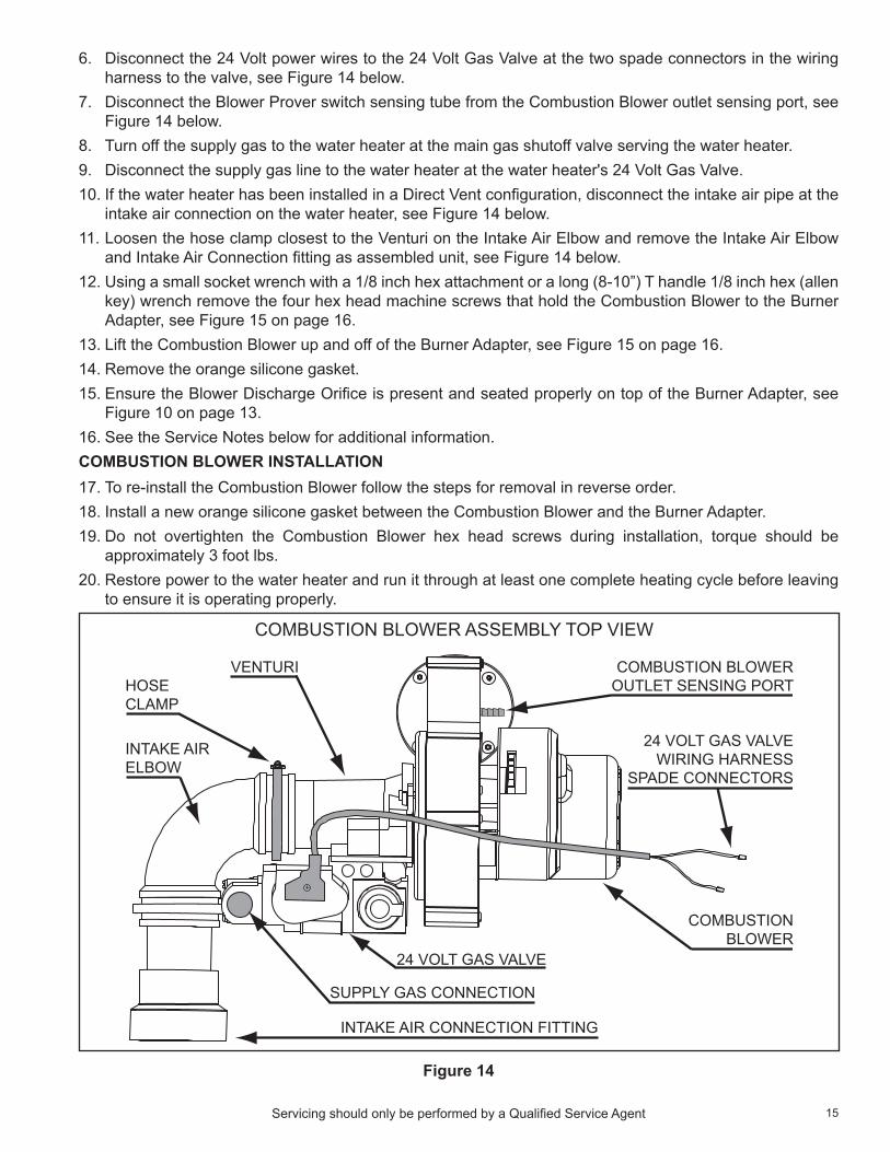
6. disconnect the 24 Volt power wires to the 24 Volt Gas Valve at the two spade connectors in the wiring harness to the valve, see Figure 14 below.
7. disconnect the Blower Prover switch sensing tube from the Combustion Blower outlet sensing port, see Figure 14 below.
8. Turn off the supply gas to the water heater at the main gas shutoff valve serving the water heater.9. disconnect the supply gas line to the water heater at the water heater's 24 Volt Gas Valve.10. If the water heater has been installed in a direct Vent configuration, disconnect the intake air pipe at the
intake air connection on the water heater, see Figure 14 below.11. Loosen the hose clamp closest to the Venturi on the Intake Air Elbow and remove the Intake Air Elbow
and Intake Air Connection fitting as assembled unit, see Figure 14 below.12. using a small socket wrench with a 1/8 inch hex attachment or a long (8-10”) T handle 1/8 inch hex (allen
key) wrench remove the four hex head machine screws that hold the Combustion Blower to the Burner Adapter, see Figure 15 on page 16.
13. Lift the Combustion Blower up and off of the Burner Adapter, see Figure 15 on page 16.14. Remove the orange silicone gasket.15. Ensure the Blower discharge orifice is present and seated properly on top of the Burner Adapter, see
Figure 10 on page 13.16. See the Service notes below for additional information.Combustion blower installation17. To re-install the Combustion Blower follow the steps for removal in reverse order.18. Install a new orange silicone gasket between the Combustion Blower and the Burner Adapter.19. do not overtighten the Combustion Blower hex head screws during installation, torque should be
approximately 3 foot lbs.20. Restore power to the water heater and run it through at least one complete heating cycle before leaving
to ensure it is operating properly.
INTAKE AIR CONNECTION FITTING
VENTURI
COMBUSTION BLOWER ASSEMBLY TOP VIEW
HOSECLAMP
INTAKE AIRELBOW
COMBUSTION BLOWEROUTLET SENSING PORT
24 VOLT GAS VALVEWIRING HARNESS
SPADE CONNECTORS
SUPPLY GAS CONNECTION
24 VOLT GAS VALVE
COMBUSTIONBLOWER
Figure 14

16 Servicing should only be performed by a Qualified Service Agent
Figure 15burner assembly removal1. Follow the instructions to remove the Combustion Blower beginning on page 14.2. Remove the Blower discharge orifice from the top of the Burner Adapter.3. unplug the Burner Adapter wiring harness; three male/female spade connections for the Igniter and
Flame Sensor behind the CCB enclosure, see Figure 10 on page 13.4. using a socket wrench with a 1/2 inch deep well socket remove the four 1/2 inch nuts from the studs
holding the Burner Adapter in place, see Figure 16 on page 17 and Figure 17 on page 17.5. Slide the Burner ground wire eyelet connector up and off of the 1/2 inch stud it is secured to. This ground
wire must be put back in place when reinstalling the Burner Assembly, see Figure 16 on page 17.6. Ensure there are not any loose parts, tools, screws or objects of any kind on top of the water heater
before removing the Burner Assembly. If any loose objects present store them in a different location.7. Carefully lift the Burner Assembly straight up and out of the water heater's heat exchanger opening, see
Figure 17 on page 17.8. Inspect the Flame Sensor and its ceramic insulator for cracks and wear. Replace the Flame Sensor if it
shows any sign of damage or excessive wear, see Figure 19 on page 19.9. Ensure the Flame Sensor is not touching the Burner surface, the gap should be approximately 1/2 inch.10. Ensure the Flame Sensor mounting screw is tight.11. Always clean the flame sensor with ultra fine steel wool while the Burner Assembly is out. do not use a
harsh abrasives such as sand paper to clean the Flame Sensor.12. Inspect the Burner Adapter wiring harness and wiring harness grommet, replace the wring harness if it
shows any sign of excessive wear or damage, see Figure 8 on page 12 and Figure 12 on page 13.13. Inspect the Igniter. Replace the Igniter if it shows any sign of damage or excessive wear.14. Ensure the Igniter mounting screw is tight.15. Remove the four 5/16 inch hex head machine screws holding the Burner to the Burner Adapter and
remove the Burner from the Burner Adapter. See Figure 5 on page 9.16. Inspect the Burner. Ensure there are not any debris inside the Burner, see the Service notes on page 5.
Replace the Burner if it is damaged or clogged with debris.

17Servicing should only be performed by a Qualified Service Agent
burner assembly installation17. To re-install the Burner Assembly follow the steps for removal in reverse order.18. Install a new white fiber gasket between the Burner Adapter and the Heat Exchanger Flange on top of
the water heater. Install a new white fiber gasket between the Burner and the Burner Adapter also. See Figure 5 on page 9.
19. do not overtighten the 5/16 inch hex head machine screws holding the Burner to the Burner Adapter or the 1/2 inch nuts that hold the Burner Adapter to the Heat Exchanger Flange on top of the water heater storage tank.
20. Restore power to the water heater and run it through at least one complete heating cycle before leaving to ensure it is operating properly.
FOUR 1/2 INCHNUTS AND STUDS
BURNERGROUNDWIRE
BURNER SIGHT GLASSWIRING HARNESS COVERPLATE AND GASKET.
TWO PHILLIPS HEADSCREWS HOLD COVERPLATE AND GASKET INPLACE.
Figure 16
Figure 17

18 Servicing should only be performed by a Qualified Service Agent
flame sensorIgnition of the Burner is controlled electronically. The principle of operation for electronic ignition relies on flame sensing current to prove the fuel gas flowing to the Burner has been ignited and is burning safely.Flame sensing requires correct power supply polarity and an adequate earth ground to the water heater's Burner, see Electrical Requirements and the Power Supply Test on page 6. See Figure 16 on page 17 for the Burner ground wire location.flame sensing operation• The Flame Sensor is a metal (conductor) rod mounted in a ceramic insulator.• The Control System applies an AC voltage to the Flame Sensor through a single wire.• The burner flame will conduct a small amount of electrical current.• The burner must be grounded for current to flow from the Flame Sensor to the Burner.• during ignition the burner flame must make complete and continuous contact with the Flame Sensor.• As the AC voltage flows from the Flame Sensor through the burner flame to the (grounded) Burner the
AC voltage is "rectified" and becomes a dC voltage.• The current flowing between the Flame Sensor and Burner is dC micro amp current expressed as: µA.
Flame sensing current can be measured with a dC micro amp test meter, see Tools Required on page 2.
IGNITER
BURNERFLAME
BURNER(MUST BE GROUNDED)
CERAMIC INSULATOR
FLAME SENSOR
METAL CONDUCTOR
CONTROL SYSTEMAPPLIES AC VOLTAGETO FLAME SENSOR
AC VOLTAGE FLOWS FROM THE FLAME SENSOR TO THE BURNER. THE BURNERMUST BE GROUNDED FOR CURRENT TOFLOW. DURING THIS PROCESS THE ACVOLTAGE IS “RECTIFIED” AND BECOMES A DC VOLTAGE. DC MICRO AMP CURRENTTHEN FLOWS BETWEEN THE FLAME SENSORAND THE BURNER.
GAP BETWEEN THE FLAME SENSOR AND THEBURNER SHOULD BE APPROXIMATELY 1/2 INCH
Figure 18
minimum flame sensing CurrentTo prove burner flame during the Ignition Verification state the Control System monitors flame sensing current; the dC micro amp (μA) current flowing through the Flame Sensor. The Control System must sense a minimum amount of current to “prove” flame. The minimum flame sensing current is 1.0 μA. If flame sensing current does not reach 1.0 µA during ignition or falls below this amount during a heating cycle the Control System will immediately de-energize the 24 Volt Gas Valve. After 3 failed trials for ignition the Control System will lock out and display Ignition Failure (fault condition) on the LCd. If flame sensing current drops below 1.0 μA during a heating cycle the Control System will de-energize the 24 Volt Gas Valve and enter the Inter-Purge operating state, see operating States on page 48. After the Inter-Purge operating state the Control System will try for ignition again if a call for heat is still active, see the Sequence of operation on page 54.

19Servicing should only be performed by a Qualified Service Agent
flame sensing Current testduring the heating cycle the flame sensing current is normally between 8.0 μA and 12.0 μA with a clean Flame Sensor. over time the Flame Sensor will accumulate corrosion (rust) and this will reduce flame sensing current. With heavier use, more heating cycles/greater load, corrosion will occur more quickly.
Measuring flame sensing current requires a test meter with a dC micro amp function, see Tools Required on page 2. The meter’s selector is set to dC micro amps. The two test leads from the meter are placed in series with the flame sensing circuit. This can be done at the spade (male/female) wiring connectors behind the CCB enclosure or at the J4 spade connection on the CCB circuit board. See Figure 19 below and the CCB Circuit Board Layout on page 41.To measure flame sensing current turn off power to the water heater and connect the test meter following one of the two methods shown in Figure 19. Restore power and ensure a call for heat is active - when the Control System energizes the 24 Volt Gas Valve the meter will measure flame sensing current during normal operation.
FLAME SENSOR
CERAMIC INSULATOR
FLAME SENSING TEST BEHINDTHE CCB ENCLOSURE
FLAME SENSING TEST INSIDETHE CCB ENCLOSURE
CCB J4 FLAME SENSORCONNECTION
IGNITER/FLAME SENSORWIRING HARNESS FROM CCB
WIRE FROMFLAME SENSOR
WIRE FROMFLAME SENSOR
Figure 19
Service Notes:• The Flame Sensor wire behind the CCB is one of three wires in a harness that also serves the Igniter.
Ensure you have identified the correct wire before performing a flame sensing test to prevent damage to the test meter. A female spade connector is used at the end of the wring harness from the CCB for the Flame Sensor, two male connectors are used for the Igniter.
• The most common cause of Ignition Failure lock out is a corroded Flame Sensor. Rust/corrosion will accumulate on the Flame Sensor over time. The Flame Sensor should be inspected and cleaned anytime the measured flame sensing current is below 8 µA or the Burner has been removed. Clean the Flame Sensor with ultra fine steel wool. do noT use a coarse abrasive material such as sand paper. Inspect the ceramic insulator on the Flame Sensor for cracks, replace the Flame Sensor if it is damaged. The Combustion Blower and Burner must be removed to access the Flame Sensor, see Combustion Blower and Burner Removal on page 14.
• An open flame sensing circuit caused by disconnected or loose connectors can also cause ignition failure. Check the spade connector behind the CCB enclosure and check all wiring and wiring connections between the Flame Sensor and the J4 connector on CCB circuit board, see CCB Circuit Board Layout on page 41.
• The Burner not being grounded will cause Ignition Failure - see Electrical Requirements on page 6 and Figure 16 on page 17. Ensure the water heater and the Burner are properly grounded.

20 Servicing should only be performed by a Qualified Service Agent
igniterThe water heaters covered by this manual use a hot surface igniter (HSI). The Igniter is made of a ceramic composite material, see Figure 20 below. The Control System powers the Igniter (120 VAC) from the J5 Socket on the CCB. The Control System monitors amperage through the Igniter to ensure it is hot enough to ignite the fuel gas flowing to the Burner during ignition. The amount of Igniter amperage is proportional to its heat output; the higher the amperage is, the higher the surface temperature of the Igniter will be.
Figure 20
The Control System is programmed to verify a minimum of 0.5 AC amps during the Igniter Warm up operating state, see operating States on page 48. If the current does not reach 0.5 amps during warm up the Control System will lock out and display Low Igniter Current fault condition on the LCd. See the Sequence of operation on page 54.Igniters are wearing parts, over time hot surface igniters will wear out and must be replaced as they will no longer generate enough heat to cause ignition. The life of the Igniter is directly tied to usage; the number of heating cycles. Consider rasing the differential setting to reduce the number of heating cycles if frequent Igniter failure occurs, see operating Set Point And differential Adjustment on page 49.With age and wear the resistance of the Igniter, measured in ohms, will rise. As the resistance rises the electrical current flowing through the Igniter decreases and so does the Igniter's surface temperature. new Igniters will generally measure between 90 and 120 ohms at 77° F (25° C). The acceptable resistance for an Igniter should be less than 200 ohms. Measuring resistance is a useful test to verify if the Igniter is no longer working at all; IE: if the measured resistance is an open circuit, infinite ohms, the Igniter must be replaced. However, the resistance of the Igniter varies with temperature and with the test meter being used. Because of these variables the most reliable field test is to measure current during the Igniter Warm up operating state to verify Igniter current is above the Control System's required minimum of 0.5 AC amps.igniter Current test1. using a clamp style amp meter, clamp the jaws of the amp meter around one of the two Igniter wires at
the J5 Socket on the CCB or behind the CCB enclosure where the wiring harness from the CCB connects to the Burner Adapter wiring harness. See CCB Cover Removal And Replacement on page 40, CCB Circuit Board Layout on page 41 and Figure 21 on page 21.
2. Ensure a call for heat is active, raise the operating Set Point or dump water at a nearby fixture.3. Ensure the desktop Screen is visible on the Control System's LCd, see desktop Screen on page 46.4. Record Igniter amperage during the Igniter Warm up operating state. The Combustion Blower speed will
noticeably reduce just before the Igniter is energized and a animated lighting bolt Status Icon appears on the desktop Screen, see Status Icons on page 47.
5. If the Igniter current is less than 0.5 or zero amps, check all wring and connections between the J5 Socket on the CCB and the Burner Adapter wiring harness behind the CCB. Turn off power and check the resistance to the Igniter at the two Igniter wires from the Burner Adapter wiring harness behind the CCB. Ensure the two Igniter wires are used for this test, the Igniter wires from the Burner Adapter will both be "female" spade connectors. If it is an open circuit, infinite resistance, remove the Combustion Blower and Burner Assembly to inspect the Igniter and the Burner Adapter wiring harness. Replace the Igniter and/or Burner Adapter wiring harness if necessary. See Combustion Blower and Burner Removal on page 14.

21Servicing should only be performed by a Qualified Service Agent
IGNITER CURRENT TEST AT J5 SOCKET ON CCB
IGNITER CURRENT TEST BEHIND CCB ENCLOSURE
Figure 21
Service Notes:• The animated lighting bolt Status Icon is visible on the LCd desktop Screen during the Igniter warm up
operating state. See desktop Screen on page 46 and Status Icons on page 47.• As a visual confirmation that minimum Igniter current is present the Control System will display a check
mark next to the lighting bolt icon on the desktop Screen during the Igniter Warm up operating state.• Ensure the wiring and connections between the J5 Socket on the CCB and the Burner Adapter are not
broken, pinched or disconnected.• Ensure there is approximately 120 VAC at the J5 Socket on the CCB during Igniter Warm up.• It is a good practice to check igniter current when any service or maintenance is being performed.
Igniter current will be approximately 0.60 to 0.70 AC amps when the Igniter is new. Because hot surface igniters are wearing parts they can cause intermittent ignition failure with age and wear. Replacing the Igniter when current is lower than 0.55 AC amps is a good preventive maintenance procedure that can prevent loss of hot water and customer dissatisfaction.

22 Servicing should only be performed by a Qualified Service Agent
venturiA Venturi is mounted on the inlet of the Combustion Blower. All combustion air flows through the Venturi. The outlet of the 24 Volt Gas Valve connects directly to the side of the Venturi. Fuel gas flows from the outlet of the 24 Volt Gas Valve into the side of the Venturi directly.Inside the Venturi there is a cone shaped restrictor that constricts the air passage to the Combustion Blower inlet. As air enters the constriction point it’s velocity increases. A pressure drop occurs at this point and creates a negative pressure in the cavity between the cone shaped restrictor and the Venturi housing. This negative pressure “pulls” gas from the outlet of the 24 Volt Gas Valve into the Combustion Blower where it is mixed with combustion air and then supplied to the Burner. See Figure 22 below.This gas feed system does not produce a typical manifold gas pressure to the Burner. The manifold (offset) gas pressure, gas pressure to the Burner, is very low. See Gas Pressure on page 25.
Negative Pressure
Negative Pressure
Velocity IncreasesAt Constriction Point
Pressure Drops
GA
SVA
LVE
Combustion Air
VENTURI
VENTURI INLET
GAS INLET24 VOLT GAS VALVE
BLOWER
BLOWER
SUPPLY GAS
BURNER
Figure 22

23Servicing should only be performed by a Qualified Service Agent
gas valveThe 24 Volt Gas Valve on these water heaters is dC voltage valve. The CCB sends 24 VAC to the valve and the AC voltage is rectified into a dC voltage by electronics contained inside the plug end of the 24 Volt Gas Valve wiring harness, see Figure 23 below.
VENTURI
24 VOLT GAS VALVE ASSEMBLY TOP VIEW
24 VAC FROM THE J6 SOCKETON THE CCB CONNECTS TOTHESE TWO SPADE TERMINALSAT THE END OF THE 24 VOLTGAS VALVE WIRING HARNESS.
SUPPLY GAS CONNECTION
24 VOLT GAS VALVE
PLUG RETAININGSCREW
24 VOLT GAS VALVEWIRING HARNESS
24 VOLT GAS VALVE WIRINGHARNESS PLUG. 24 VACFROM CCB IS RECTIFIED TO24 VDC BY ELECTRONICSINSIDE THE PLUG END.
COMBUSTIONBLOWER
Figure 23
gas valve voltage tests1. Check for 24 VAC supplied to the 24 Volt Gas Valve at pins 2 and 15 of the J6 Plug on the CCB, see
CCB Cover Removal And Replacement on page 40 and CCB Circuit Board Layout on page 41. using an "AC" volt meter insert the two test probes into pins 2 and 15 of the J6 Plug on the CCB during the Ignition Verification or Heating operating states, see Figure 24 below. 24 VAC should be present. The animated gas valve Status Icon is displayed on the Control System LCd during these operating states. See operating States on page 48 and desktop Screen on page 46.
2. Check for 24 VdC at the plug end of the 24 Volt Gas Valve wiring harness during the Ignition Verification operating state. Loosen the retaining screw for the 24 Volt Gas Valve wiring harness plug and disconnect the plug, see Figure 23 above. Lay the plug end upside down on a flat surface. using an "dC" volt meter insert the two test probes into the two outside plug sockets, see Figure 24 below. 24 VdC should be present.
AC VOLTAGE TEST DC VOLTAGE TEST
Figure 24

24 Servicing should only be performed by a Qualified Service Agent
gas valve removalThe outlet of the 24 Volt Gas Valve is connected by flange directly to the side of the Venturi and is secured by three - 5/32” hex head screws. A gas orifice with gasket is fitted into the gas valve’s outlet flange, see Figure 25 and Figure 26 below. The 24 Volt Gas Valve must be removed to inspect the gas orifice. Ensure there is a new gasket on hand before removing the valve. Call the toll free phone number on the back cover of this manual to order parts. Have the complete Model, Series and Serial number (located on the water heater's rating label) for the water heater being serviced on hand before calling.1. If the water heater is in a heating cycle lower the operating Set Point to end the cycle, see Temperatures
on page 49.2. Turn off power to the water heater at the water heater's on/off switch.3. Loosen the retaining screw for the wiring harness plug on the valve and disconnect the plug, see Figure
23 on page 23. 4. Turn off the supply gas to the water heater at the main gas shutoff valve serving the water heater.5. disconnect the supply gas line to the water heater at the water heater's 24 Volt Gas Valve.6. If the water heater has been installed in a direct Vent configuration, disconnect the intake air pipe at the
intake air connection on the water heater.7. Loosen the hose clamp closest to the Venturi on the Intake Air Elbow and remove the Intake Air Elbow
and Intake Air Connection fitting as assembled unit, see Figure 14 on page 15.8. Remove 3 gas valve mounting screws - 5/32” hex head machine screws, see Figure 25 below.9. Carefully lift 24 Volt Gas Valve body off of the Venturi.10. Follow these steps in reverse order to reinstall the 24 Volt Gas Valve.11. Run the water heater through a complete heating cycle before leaving to ensure it is operating properly.
24 VOLT GAS VALVE
VENTURI
5/32 INCHHEX WRENCH
GAS ORIFICE& GASKET
Figure 25
GAS ORIFICE
GAS ORIFICE SIZESNATURAL GAS: 0.191”PROPANE GAS: 0.162”
GASKET
Figure 26

25Servicing should only be performed by a Qualified Service Agent
gas pressureThe water heater covered in this Service Manual is rated at 100,000 Btu/hr input. It is certified for elevations up to 10,100 feet (3,078 meters). For higher elevations call the toll free support phone number shown on the back cover of this manual for technical assistance.table 2
†MAnIFoLd oFFSET PRESSuRE MInIMuM SuPPLy PRESSuRE MAxIMuM SuPPLy PRESSuRE
NATURAl GAS PROPANE GAS NATURAl GAS PROPANE GAS NATURAl GAS PROPANE GAS0.24” W. C. (0.056 kPa) 0.17” W. C. (0.042 kPa) 3.5” W. C. (0.87 kPa) 8” W. C. (1.20 kPa) 14” W. C. (3.49 kPa) 14” W. C. (3.49 kPa)
† Manifold offset pressures will vary. See the Service notes below.
Service Notes:• The manifold "offset" gas pressure is factory set and cannot be adjusted in the field.• The manifold offset gas pressure and the supply gas pressure can be measured at two pressure test
ports on the water heater’s 24 Volt Gas Valve, see Figure 27 below. The manifold offset pressure test port is closest to the Combustion Blower, see Figure 28 on page 26. There is a needle valve in each test port that is opened/closed with a small slotted screwdriver. Turn the needle valve counter-clockwise to open the test port valve and clockwise to close it.
• Manifold offset gas pressure will run close to 0” W.C. or lower (in a vacuum) depending on the current operating state, see operating States on page 48. This pressure will be considerably lower, -5.00” W.C. to -7.50” W.C. during the Pre- Purge and Post-Purge operating states when the Combustion Blower is running at high speed and the 24 Volt Gas Valve is closed, see Venturi on page 22.
• When the 24 Volt Gas Valve opens gas entering the Venturi will cause a rise in manifold offset gas pressure. Manifold offset gas pressures will typically be +0.24” W.C. on natural gas models and +0.17” W.C. on propane gas models during the Heating operating state. Keep in mind these pressures are approximate and will vary depending on the equivalent length of the vent and/or intake air pipe installed.
• There is usually a drop in supply gas pressure noticed when the water heater’s 24 Volt Gas Valve opens during ignition. Seeing a corresponding rise in manifold offset pressure during ignition confirms the valve is opening and gas is flowing to the Burner, see Gas Flow Test on page 27.
• A sustained drop in supply gas pressure of 1.5" W.C. or more during ignition may indicate the supply gas line is undersized. If the water heater is experiencing a sustained drop in supply gas pressure of 1.5" W.C. or more and the water heater is experiencing repeated Ignition Failure fault conditions, intermittent loss of flame or rough starting ensure the supply gas line is sized in accordance with the current edition of national Fuel Gas Code (AnSI Z223.1/nFPA 54) or the natural Gas and Propane Installation Code (CAn/CSA B149.1).
VENTURI
SUPPLY GASCONNECTION
PRESSURETEST PORTS
COMBUSTIONBLOWERCONNECTION
24 VOLT GAS VALVE
COMBUSTIONAIR INLET
Figure 27

26 Servicing should only be performed by a Qualified Service Agent
gas pressure test1. If the water heater is in a heating cycle lower the operating Set Point to end the cycle, see Temperatures
on page 49.2. Turn off power to the water heater at the water heater's on/off switch.3. Turn off the supply gas to the water heater at the main gas shutoff valve serving the water heater.4. open the manifold offset and supply gas pressure test ports on the 24 Volt Gas Valve, see Figure 28 below.
Turn the needle valve slotted heads 1/2 to 1 full turn counter-clockwise with a small slotted screwdriver to open the valves.
5. Attach a sensing tube from 2 digital manometers (see Tools Required on page 2) to the two gas pressure test ports on the valve body as shown in Figure 28 below.
6. open the main gas shutoff valve serving the water heater.7. The manometer connected to the supply gas pressure test port should read the "static" (gas is not
flowing) supply gas pressure. 8. Record the supply gas pressure.9. Record the manifold offset pressure (should be at or near 0" W.C. - Combustion Blower is off).10. Restore power - and raise the operating Set Point to initiate a heating cycle.11. Record the manifold offset pressure when the Combustion Blower starts and ramps up to high speed
during the Pre-Purge operating state (should be in a deep vacuum; -5.00” W.C. to -7.50” W.C.)12. Return the Control System LCd to the desktop Screen, see desktop Screen on page 46.13. Record the manifold offset pressure and the supply gas pressure when the Ignition Activation operating
state begins; when the animated gas valve Status Icon appears on the desktop Screen.• The manifold offset pressure should rise to near 0" W.C. as the 24 Volt Gas Valve opens.• The supply gas pressure will typically drop as the 24 Volt Gas Valve opens.
Putting The Water Heater Back In Service14. Lower the operating Set Point to end the heating cycle.15. Close the main gas shutoff valve serving the water heater.16. disconnect manometer sensing tubes.17. Close the manifold offset and supply gas pressure test ports on the 24 Volt Gas Valve. Turn the needle
valve slotted heads clockwise until tight.18. open the main gas shutoff valve serving the water heater and check for leaks at the gas valve test ports.19. Restore power to the water heater and raise the operating Set Point to activate a call for heat.20. Run the water heater through a complete heating cycle before leaving to ensure it is operating properly.
MANIFOLD OFFSETPRESSURE TEST PORT
SUPPLY GASPRESSURETEST PORT
Figure 28

27Servicing should only be performed by a Qualified Service Agent
gas flow testThe following illustrations show the approximate pressures for the manifold offset and supply gas for the Standby, Pre-Purge and Heating operating states during a normal heating sequence. notice how the manifold offset pressure starts at 0" W.C. in the Standby operating state, falls to a deep vacuum during the Pre-Purge state and then rises to a slight positive pressure when the 24 Volt Gas Valve is energized during the Heating state. Also notice how the supply gas pressure remains constant until the 24 Volt Gas valve is energized at which point it drops slightly.Follow the procedure to connect two digital manometers to the 24 Volt Gas Valve in the Gas Pressure Test on page 26. observe the pressure changes during the three operating states listed in Figure 29 below.The drop in supply pressure and corresponding rise in manifold offset pressure, between Steps 2 and 3, proves the 24 Volt Gas valve is opening and that fuel gas is flowing through the valve.
CONDITIONS:• COMBUSTION BLOWER OFF• 24 VOLT GAS VALVE OFF
PRESSURE READINGS:• MANIFOLD OFFSET:• SUPPLY GAS:
0.00” W.C.+8.41” W.C.
OPERATING STATE:• PRE-PURGE
OPERATING STATE:• STANDBY
OPERATING STATE:• HEATING
1
2
3
CONDITIONS:• COMBUSTION BLOWER ON• 24 VOLT GAS VALVE OFF
PRESSURE READINGS:• MANIFOLD OFFSET:• SUPPLY GAS:
-5.33” W.C.+8.41” W.C.
CONDITIONS:• COMBUSTION BLOWER ON• 24 VOLT GAS VALVE ON
PRESSURE READINGS:• MANIFOLD OFFSET:• SUPPLY GAS:
0.07” W.C.+7.75” W.C.
Figure 29
28 Servicing should only be performed by a Qualified Service Agent
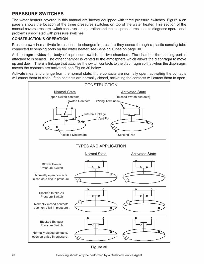
pressure switChesThe water heaters covered in this manual are factory equipped with three pressure switches. Figure 4 on page 9 shows the location of the three pressures switches on top of the water heater. This section of the manual covers pressure switch construction, operation and the test procedures used to diagnose operational problems associated with pressure switches. ConstruCtion & operationPressure switches activate in response to changes in pressure they sense through a plastic sensing tube connected to sensing ports on the water heater, see Sensing Tubes on page 30.A diaphragm divides the body of a pressure switch into two chambers. The chamber the sensing port is attached to is sealed. The other chamber is vented to the atmosphere which allows the diaphragm to move up and down. There is linkage that attaches the switch contacts to the diaphragm so that when the diaphragm moves the contacts are activated, see Figure 30 below.Activate means to change from the normal state. If the contacts are normally open, activating the contacts will cause them to close. If the contacts are normally closed, activating the contacts will cause them to open.
Vent Port
Sensing PortFlexible Diaphragm
Wiring TerminalsSwitch Contacts
Normal State(open switch contacts)
Activated State(closed switch contacts)
Internal Linkage
Normal State Activated State
Blower Prover Pressure Switch
Normally open contacts ,close on a rise in pressure .
Blocked ExhaustPressure Switch
Normally closed contacts, open on a rise in pressure .
Blocked Intake Air Pressure Switch
Normally closed contacts,open on a fall in pressure .
CONSTRUCTION
TYPES AND APPLICATION
Figure 30

29Servicing should only be performed by a Qualified Service Agent
Control system monitoringThe Control System monitors the “state” of the pressure switch contacts individually through three separate circuits, see Wiring diagram on page 44. The state of the switch refers to whether the switch contacts are open or closed, see Construction & operation on page 28.At the beginning of a heating sequence, before the Combustion Blower is energized, the Control System enters the Input Verification operating state, see operating States on page 48. during Input Verification the Control System monitors all three pressure switches to ensure their contacts are in the correct "normal" state. The Blower Prover switch contacts must be open, the contacts for the Blocked Intake Air and Blocked Exhaust switches must be closed, see Figure 30 on page 28 and the Sequence of operation on page 54.If any of the pressure switch contacts are not in their correct normal state during Input Verification the Control System will lock out and display a fault message on the LCd indicating which pressure switch caused the fault condition, see Figure 31 below. If all system checks pass during the Input Verification operating state the Control System enters the Pre-Purge operating state and energizes the Combustion Blower.After the Combustion Blower is energized the Control System must confirm the Blower Prover switch contacts have closed, see the Sequence of operation Flow Chart on page 55. The Blocked Intake Air and Blocked Exhaust switch contacts must remain closed at all times.If the Blower Prover switch contacts are closed during the Input Verification the Control System will lock out and display Blower Prover Failure on the LCd. If the Blower Prover switch contacts do not close after the Combustion Blower is energized the Control System will lock out and display Blower Prover Open on the LCd. If either the Blocked Intake Air or Blocked Exhaust switch contacts open at any time during a heating sequence the Control System will lock out and display Blocked Air Intake or Blocked Exhaust on the LCd. See Figure 31 below.
CHANGE BACK ADVANCED
Blower Prover FailureFault occurred 2 mins ago
The blower prover switch isclosed out of sequence.
Call a service professional:Your Company Name Here(press [DOWN] for more....)
CHANGE BACK ADVANCED
Blower Prover OpenFault occurred 2 mins ago
The blower prover switch remainsopen after the blower has beenenergized.
Call a service professional:Your Company Name Here(press [DOWN] for more....)
CHANGE BACK ADVANCED
Blocked Air IntakeFault occurred 2 mins ago
The combustion air intake isrestricted.
Call a service professional:Your Company Name Here(press [DOWN] for more....)
CHANGE BACK ADVANCED
Blocked ExhaustFault occurred 2 mins ago
The exhaust is blocked orrestricted. Ensurecondensate hose is draining.
Call a service professional:Your Company Name Here(press [DOWN] for more....)
PRESSURE SWITCH FAULT MESSAGES
Figure 31
30 Servicing should only be performed by a Qualified Service Agent
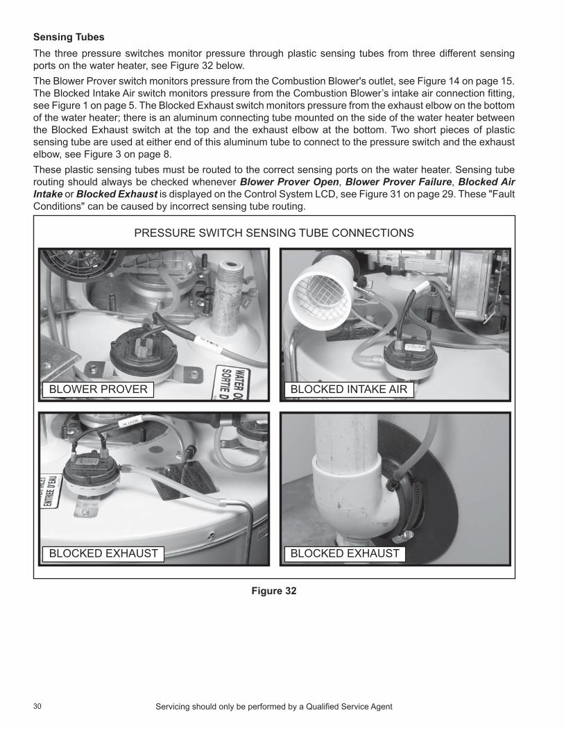
Sensing TubesThe three pressure switches monitor pressure through plastic sensing tubes from three different sensing ports on the water heater, see Figure 32 below.The Blower Prover switch monitors pressure from the Combustion Blower's outlet, see Figure 14 on page 15. The Blocked Intake Air switch monitors pressure from the Combustion Blower’s intake air connection fitting, see Figure 1 on page 5. The Blocked Exhaust switch monitors pressure from the exhaust elbow on the bottom of the water heater; there is an aluminum connecting tube mounted on the side of the water heater between the Blocked Exhaust switch at the top and the exhaust elbow at the bottom. Two short pieces of plastic sensing tube are used at either end of this aluminum tube to connect to the pressure switch and the exhaust elbow, see Figure 3 on page 8.These plastic sensing tubes must be routed to the correct sensing ports on the water heater. Sensing tube routing should always be checked whenever Blower Prover Open, Blower Prover Failure, Blocked Air Intake or Blocked Exhaust is displayed on the Control System LCd, see Figure 31 on page 29. These "Fault Conditions" can be caused by incorrect sensing tube routing.
BLOWER PROVER BLOCKED INTAKE AIR
PRESSURE SWITCH SENSING TUBE CONNECTIONS
BLOCKED EXHAUST BLOCKED EXHAUST
Figure 32

31Servicing should only be performed by a Qualified Service Agent
pressure switCh testsComplete pressure switch testing involves three procedures:
• Continuity Test during Standby below.• Continuity Test during operation on page 32.• Pressure Test during operation on page 32.
Continuity test during standbyThis test is performed while the Combustion Blower is not running with the water heater turned off. This is a "normal state" continuity test of the contacts inside each pressure switch. disconnect the two wires to each pressure switch for this test.1. If the water heater is in a heating cycle lower the operating Set Point to end the cycle, see Temperatures
on page 49.2. Turn off power to the water heater at the water heater's on/off switch.3. disconnect both wires at each pressure switch.4. using an ohm meter set for continuity testing, check for continuity between the two wiring terminals at
each pressure switch, see Figure 33 below.Results/ActionsPassed Results: If the Blower Prover switch contacts are open during this test (infinite ohms/open circuit) the Blower Prover switch has passed the test. If the Blocked Intake Air and Blocked Exhaust switch contacts are closed during this test, (zero ohms/direct short), these switches have passed the test.Failed Results: If the Blower Prover switch contacts are closed (zero ohms/direct short) during this test, the Blower Prover switch must be replaced. If the Blocked Intake Air and/or Blocked Exhaust switch contacts are open during this test, the switch(s) must be replaced.Proceed to the Continuity Test during operation on page 32.
Figure 33

32 Servicing should only be performed by a Qualified Service Agent
Continuity test during operationThis test is performed while the Combustion Blower is running at high speed during the Pre-Purge operating state. The test is performed on all three pressure switches. disconnect the two wires to each pressure switch - one at a time, check continuity and then reconnect the wires to that switch before testing the next switch.1. Ensure power to the water heater is turned off at the water heater's on/off switch.2. Ensure the sensing tubes from each pressure switch are connected to the correct sensing port on the
water heater, see Sensing Tubes on page 30.3. disconnect the two wires for the switch to be tested.4. When testing the Blocked Exhaust and Blocked Intake Air switches, connect a small jumper wire to the
short the two wires disconnected. This will temporarily prevent the Control System from locking out during the test. When the test for these two switches is complete, remove the jumper wire and reconnect the pressure switch wiring before moving on to the next switch.
5. Restore power to the water heater, if the water heater does not begin a heating cycle raise the operating Set Point to activate a heating cycle.
6. using an ohm meter set for continuity testing, check for continuity between the two wiring terminals at the pressure switch after the Combustion Blower has started and ramped up to high speed during the Pre-Purge operating state, see Figure 33 on page 31. Record the results; open or closed.
7. Repeat this procedure for each pressure switch.8. Ensure the wires to all pressure switches are reconnected when testing is complete.Results/ActionsPassed Results: If the Blower Prover switch contacts activate/close (zero ohms/direct short) during this test the switch has passed this test. If the Blocked Intake Air and Blocked Exhaust switch contacts remain closed during this test, (zero ohms/direct short), these switches have passed the test.Failed Results: If the Blower Prover switch contacts do not close during this test, the Pressure Test during operation below must be performed to determine if the switch is defective. If the Blocked Intake Air or Blocked Exhaust switch contacts open during this test, the Pressure Test during operation below must be performed to determine if the switch(s) is defective.Proceed to the Pressure Test during operation below.
pressure test during operationThis test will be performed while the Combustion Blower is running at high speed during the Pre-Purge operating state. This test is necessary when a pressure switch has passed the Continuity Test during Standby on page 31 but has failed the Continuity Test during operation above to determine if the pressure switch is defective or not. This test requires a digital manometer, see Tools Required on page 2.Service Notes:• Before performing this test examine the sensing tube connections on the water heater’s sensing ports
and on the pressure switch. Check for wear, cracks, leaks, kinks, or any kind of debris or condensate in the sensing tubes, repair/replace as necessary.
• To determine if a pressure switch is operating properly you must first know the "switch action" (whether the switch activates on a rise or a fall in pressure) and the "activation pressure" the switch will activate at. Activation pressures are provided in Table 3 on page 33. Switch actions are as follows:• Blower Prover switch - normally open contacts, close on a rise in pressure.• Blocked Intake Air switch - normally closed contacts, open on a fall in pressure.• Blocked Exhaust switch - normally closed contacts, open on a rise in pressure.
Activation PressuresTable 3 on page 33 shows the activation pressures and tolerance for each of the three pressure switches. A + sign before the pressure indicates a positive pressure; above atmospheric pressure. A - sign before the pressure indicates a negative pressure (in a vacuum); below atmospheric pressure. Tolerances are specified to allow reasonable leeway for imperfections and inherent variability without compromising performance.

33Servicing should only be performed by a Qualified Service Agent
table 3
blower prover blocked intake air Blocked Exhaust†Activation Pressure +0.75" W.C. -2.00" W.C. +2.00" W.C.
Tolerance ± 0.05" W.C. ± 0.05" W.C. ± 0.05" W.C.†Though it is uncommon, pressure switch specifications can be changed by the manufacturer. These activation pressures are current as of the (month/year - expressed as MM/yy) date code printed on the front cover of this manual in the lower left corner. If the accuracy of these specifications are in doubt call the toll free support phone number on the back cover of this manual to verify.
Pressure Test:1. Ensure power to the water heater is turned off at the water heater's on/off switch.2. disconnect the sensing tube from the switch being tested. 3. Connect a digital manometer to the sensing tube disconnected above or connect a longer manometer
sensing tube to the port on the water heater if needed, see Figure 32 on page 30 and Figure 34 on page 34.4. Restore power to the water heater, if the water heater does not begin a heating cycle raise the operating
Set Point to activate a heating cycle.5. When the Combustion Blower comes on and ramps up to full speed, record the pressure reading. 6. Repeat this test for all three pressure switches as necessary. 7. Compare the pressure readings taken to the activation pressures in Table 3 above.8. Ensure all sensing tubes are properly routed and reconnected when testing is complete, see Sensing
Tubes on page 30.Results/Actionsblower prover: If the pressure reading taken at the Blower Prover switch sensing tube is at or above the activation pressure shown in Table 3 and the switch contacts did not close during the Continuity Test during operation on page 32 - the switch is defective and must be replaced. If the pressure reading taken does not reach or rise above the activation pressure in Table 3 the pressure switch is not defective and should not be replaced - call the toll free phone number on the back cover of this manual for further technical assistance. Have the complete Model, Series and Serial number (located on the water heater's rating label) for the water heater being serviced on hand before calling.blocked intake air: note these are negative pressures; in a vacuum. If the pressure reading taken at the Blocked Intake Air switch sensing tube does not reach or drop lower than the pressure shown in Table 3 and the switch contacts were opening during the Continuity Test during operation on page 32 - the switch is defective and must be replaced. If the pressure reading taken reaches or drops lower than the pressure shown in Table 3 and the switch contacts were opening during the Continuity Test during operation on page 32 - the switch is not defective and should not be replaced. Check for restrictions at the intake air connection on the water heater, check for too small of pipe installed, too many equivalent feet and/or too many elbows in the intake air piping. Check for low points in the intake air piping where water may be collecting and blocking the intake air piping. Check for any restrictions or debris at the intake air termination outdoors. Check for condensate/water in the sensing tube/switch, if the sensing tube has water in it, replace the Blocked Intake Air switch and the tube. Ensure the sensing port is oriented properly, see Intake Air Connection on page 5.Blocked Exhaust: If the pressure reading taken at the Blocked Exhaust switch sensing tube does not reach or rise above the activation pressure given in Table 3 and the switch contacts were opening during the Continuity Test during operation on page 32 - the switch is defective and must be replaced. If the pressure reading taken reaches or exceeds the pressure shown in Table 3 and the switch contacts were opening during the Continuity Test during operation on page 32 - the switch is not defective and should not be replaced. Ensure the condensate drain connected to the exhaust elbow on the water heater is not clogged and is draining freely. Check for restrictions or blockage in the vent pipe, check for too small of pipe installed, too many equivalent feet and/or too many elbows in the vent piping. Check for low points in the vent pipe where water may be collecting and blocking the vent piping. Check for any restrictions or debris at the vent termination outdoors.

34 Servicing should only be performed by a Qualified Service Agent
BLOWER PROVER SWITCHPRESSURE TEST
BLOCKED INTAKE AIR SWITCHPRESSURE TEST
BLOCKED EXHAUST SWITCHPRESSURE TEST
Figure 34

35Servicing should only be performed by a Qualified Service Agent
temperature probeThis section of the manual provides information on the Temperature Probe, see Figure 3 on page 8 for location. The Temperature Probe contains the ECo (energy cut out) and a Temperature Sensor. The Temperature Probe connects to the J7 Socket on the CCB, see CCB Circuit Board Layout on page 41 and CCB Connection Identification on page 42.eCo high temperature limit switChThe ECo (energy cut out) is a high temperature limit switch
designed to protect against excessively high water temperatures inside the water heater's storage tank. The ECo is a normally closed switch that opens on a rise in temperature. The ECo switch is located inside the Temperature Probe (two red wires). The ECo temperature setting is non adjustable; the contacts open at 201°F (94°C) and will close at approximately 140°F (60°C).The Control System constantly monitors the state of the ECo switch contacts. If the ECo activates (contacts open) due to abnormally high water temperature the Control System will lock out and display Energy Cut Out (ECO) on the LCd. Should the ECo activate, the water temperature must drop below 140°F (60°C) before the Control System can be reset. once the water temperature has cooled below this point the power supply to the water heater must be turned off and on again to reset the Control System.temperature sensorThe Temperature Sensor located inside the Temperature Probe is a “thermistor” (two black wires). Thermistors are thermally sensitive resistors. As the water temperature rises the resistance (measured in ohms) of the sensor will decrease; as the temperature falls the resistance will increase - see Table 4 on page 36.The Control System interprets changes in the temperature sensor resistance as changes in water temperature and uses this data to activate and deactivate heating cycles and displays this temperature in the Control System menus, see desktop Screen on page 46 and Temperatures Menu on page 50.The Control System constantly monitors the Temperature Sensor. The Control System is programmed to declare a fault condition if the resistance of the temperature sensor drops below 390 ohms (shorted) or above 56,000 ohms (open).If the resistance of the Temperature Sensor is below 390 ohms the Control System will lock out and display Temp Probe Short on the LCd. If the resistance of the temperature sensor is above 56,000 ohms the Control System will lock out and display Temp Probe Open on the LCd. The power supply to the water heater must be turned off and on again to reset the Control System. note; the Control System will not reset unless the condition has been corrected.temperature sensor test1. Turn off power to the water heater at the water heater's on/off switch.2. Remove the top cover on the water heater, see Figure 3 on page 8.3. disconnect the four pin plug/socket connection from the Temperature Probe outside the CCB enclosure
on the left, see Figure 35 on page 36.4. using an ohm meter: set the ohm meter range to a scale just above 30,000 ohms.5. Check resistance between the two inside pins (black wires) of the plug end from the Temperature Probe,
see Figure 35 on page 36. Compare the measured resistance to the values given in Table 4 on page 36. Temperature Probes are very reliable and should only be replaced when:• The resistance is above 56,000 ohms (open) or below 390 ohms (shorted).• The nature of the service problem is temperature control and the resistance readings are
considerably (± 25%) different than the values in Table 4 on page 36 at the given temperature.
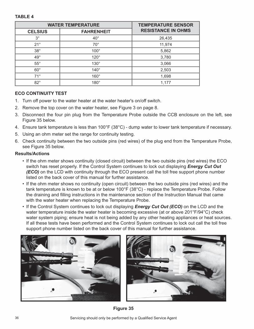
36 Servicing should only be performed by a Qualified Service Agent
TABlE 4
water temperature temperature sensor resistanCe in ohmsCelsius fahrenheit
3° 40° 26,43521° 70° 11,97438° 100° 5,86249° 120° 3,78055° 130° 3,06660° 140° 2,50371° 160° 1,69882° 180° 1,177
eCo Continuity test1. Turn off power to the water heater at the water heater's on/off switch.2. Remove the top cover on the water heater, see Figure 3 on page 8.3. disconnect the four pin plug from the Temperature Probe outside the CCB enclosure on the left, see
Figure 35 below.4. Ensure tank temperature is less than 100°F (38°C) - dump water to lower tank temperature if necessary.5. using an ohm meter set the range for continuity testing. 6. Check continuity between the two outside pins (red wires) of the plug end from the Temperature Probe,
see Figure 35 below.Results/Actions
• If the ohm meter shows continuity (closed circuit) between the two outside pins (red wires) the ECo switch has reset properly. If the Control System continues to lock out displaying Energy Cut Out (ECO) on the LCd with continuity through the ECo present call the toll free support phone number listed on the back cover of this manual for further assistance.
• If the ohm meter shows no continuity (open circuit) between the two outside pins (red wires) and the tank temperature is known to be at or below 100°F (38°C) - replace the Temperature Probe. Follow the draining and filling instructions in the maintenance section of the Instruction Manual that came with the water heater when replacing the Temperature Probe.
• If the Control System continues to lock out displaying Energy Cut Out (ECO) on the LCd and the water temperature inside the water heater is becoming excessive (at or above 201°F/94°C) check water system piping; ensure heat is not being added by any other heating appliances or heat sources. If all these tests have been performed and the Control System continues to lock out call the toll free support phone number listed on the back cover of this manual for further assistance.
Figure 35

37Servicing should only be performed by a Qualified Service Agent
Control system hardwareThis section of the manual will provide information on Control System hardware , operation and service procedures. See Control System operation on page 45 for information on Control System features, navigation, menus, and user settings.The water heaters covered in this manual are equipped with an electronic Control System that regulates water temperature inside the storage tank. Heating cycles and ignition are managed by the Control System. The ECo (energy cut out), Flame Sensor, pressure switches and Temperature Probe are monitored by the Control System. The Combustion Blower, Igniter and the 24 Volt Gas Valve are all energized by the Control System. See Features And Components on page 8 for the location of these components.ComponentsThe main components of the Control System are a uIM (user Interface Module) and a CCB (Central Control Board). The uIM is located on the top front side of the water heater, see Figure 3 on page 8. The CCB is mounted on top of the water heater inside a protective enclosure, see Figure 4 on page 9.UIM (USER INTERFACE MoDUlE)The uIM’s major components include a Circuit Board with LCd display and a Button Pad overlay which contains the five user input buttons. Figure 36 below shows these components that are located behind the control interface cover on the front of the water heater.
UIM CIRCUIT BOARD BACK
J3 SOCKET - BUTTONPAD COMMUNICATION
BUTTON PAD OVERLAY
J3 SOCKET - ENSURECABLE IS PLUGGED INEXACTLY AS SHOWN
UIM CIRCUIT BOARD FRONT
J2 SOCKET - CCBCOMMUNICATIONCAT V CABLE
LCD SCREEN
Figure 36
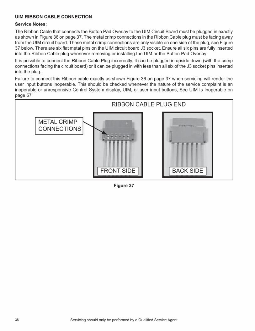
38 Servicing should only be performed by a Qualified Service Agent
uim ribbon Cable ConneCtionService Notes:The Ribbon Cable that connects the Button Pad overlay to the uIM Circuit Board must be plugged in exactly as shown in Figure 36 on page 37. The metal crimp connections in the Ribbon Cable plug must be facing away from the uIM circuit board. These metal crimp connections are only visible on one side of the plug, see Figure 37 below. There are six flat metal pins on the uIM circuit board J3 socket. Ensure all six pins are fully inserted into the Ribbon Cable plug whenever removing or installing the uIM or the Button Pad overlay. It is possible to connect the Ribbon Cable Plug incorrectly. It can be plugged in upside down (with the crimp connections facing the circuit board) or it can be plugged in with less than all six of the J3 socket pins inserted into the plug. Failure to connect this Ribbon cable exactly as shown Figure 36 on page 37 when servicing will render the user input buttons inoperable. This should be checked whenever the nature of the service complaint is an inoperable or unresponsive Control System display, uIM, or user input buttons, See uIM Is Inoperable on page 57
RIBBON CABLE PLUG END
METAL CRIMPCONNECTIONS
FRONT SIDE BACK SIDE
Figure 37
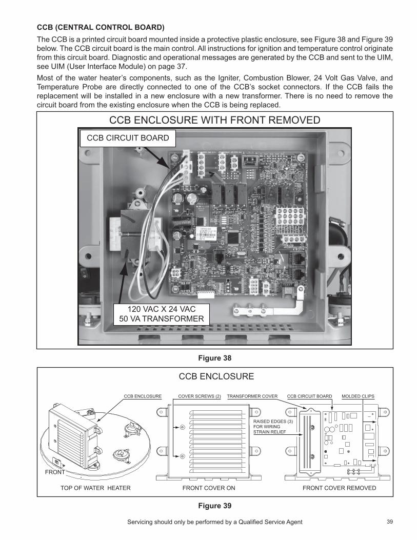
39Servicing should only be performed by a Qualified Service Agent
CCB (CENTRAl CoNTRol BoARD)The CCB is a printed circuit board mounted inside a protective plastic enclosure, see Figure 38 and Figure 39 below. The CCB circuit board is the main control. All instructions for ignition and temperature control originate from this circuit board. diagnostic and operational messages are generated by the CCB and sent to the uIM, see uIM (user Interface Module) on page 37.Most of the water heater’s components, such as the Igniter, Combustion Blower, 24 Volt Gas Valve, and Temperature Probe are directly connected to one of the CCB’s socket connectors. If the CCB fails the replacement will be installed in a new enclosure with a new transformer. There is no need to remove the circuit board from the existing enclosure when the CCB is being replaced.
CCB ENCLOSURE WITH FRONT REMOVEDCCB CIRCUIT BOARD
120 VAC X 24 VAC50 VA TRANSFORMER
Figure 38
CCB ENCLOSURE
FRONT COVER ON
FRONT
TOP OF WATER HEATER FRONT COVER REMOVED
CCB CIRCUIT BOARD MOLDED CLIPS
RAISED EDGES (3)FOR WIRINGSTRAIN RELIEF
COVER SCREWS (2)CCB ENCLOSURE TRANSFORMER COVER
Figure 39

40 Servicing should only be performed by a Qualified Service Agent
CCb Cover removal and replaCementThe cover on the CCB enclosure must be removed for various service procedures outlined in this manual. Refer to the instructions on page 40 when removing and replacing the CCB cover.Wiring to and from the CCB and other water heater components enters the CCB enclosure on the left side. Strain relief for the wiring is provided between the enclosure's front cover and the internal transformer cover. The wires and cables are held in place between the inside of front cover and three raised edges molded in the top of the internal transformer cover as the cover screws are tightened. Two screws (on the left side) and two molded clips (on the right side) hold the CCB's front cover in place, see Figure 39 on page 39.Removing the enclosure cover is a simple procedure. Care must be taken when replacing the CCB cover to ensure the wiring is routed properly and the cover is replaced correctly. Follow the procedures below to ensure the wiring is not pinched or damaged and no connectors are accidentally unplugged.Cover Removal Procedure:Refer to Figure 3 on page 8 and Figure 39 on page 39 for these instructions.1. Ensure power to the water heater is turned off.2. Remove the 4 screws that hold the top cover in place.3. Remove the 2 CCB cover screws from the CCB.4. Swing the cover away from the enclosure from left side and disengage the molded clips on the right.Cover Replacement Procedure:Refer to Figure 40 below and Figure 39 on page 39 for these instructions.1. Route all wiring and cables side-by-side flat across the transformer cover. Ensure the wiring and cables
are not stacked on top of each other as this will prevent the cover from seating properly and may damage the wiring.
2. Route all wiring and cables between the two cover screw wells on the transformer cover.3. use electrical tape to secure the wiring to the transformer cover before replacing the cover as shown.4. Replace the CCB cover by first engaging the molded clips on the right side of the enclosure with the
mating clips on the cover. Replace the CCB cover screws, do not over tighten.5. Restore power to the water heater and run it through at least one complete heating cycle before leaving
to ensure no wiring was unplugged or damaged, see the Service notes below.
Figure 40
Service Notes:If any operational problems, fault conditions or Control System lock outs occur after the CCB enclosure cover has been removed and replaced, remove the cover again to ensure none of the wiring connectors are unplugged and/or any of the wiring has been pinched, cut or damaged.

41Servicing should only be performed by a Qualified Service Agent
CCb CirCuit board layout
1 Retry
Use Yes
Type Tstat
Spare
ExtInput
3Retries
No
Vent
Spare
OPE
N
1
2 3
4
3
2
1
6
5
4
9
8
7
12
11
10
15
14
13
J6
J7 3 24 1
1
2
J15
84
5
6
7
1
2
3
J13
3
4
1
2
J10
1
3
5
2
4
J1
1
3
4
2
J2
1
4
2 1
2
J3 J5 J4
S1 DIPSWITCH
J16
J9
J11
S1 DIPSWITCH DETAIL
CCB (CENTRAL CONTROL BOARD)
1 Retry
Use Yes
Type Tstat
Spare
ExtInput
3Retries
No
Vent
Spare
OPE
N
1
2 3
4
Dipswitch Operation:Along one side of the dipswitch array there are numbers, 1-4. On the other side of the dipswitchis the word “OPEN.” The dipswitches are rocker type switches, if one side of the rocker is down the other side will be up. Pressing a rocker down on the side of the array labeled “OPEN,” opens the switch.Pressing a rocker down on the side of the array labeled with the numbers 1-4 closes the dipswitch.
CHANGING NUMBER OF IGNITION TRIALS BEFORE LOCK OUT
NOTE: Always turn off power to the water heater before changing dipswitch settings.
Set dipswitch #4 to the open position for 1 trial for ignition before Ignition Failure lock out. Set dipswitch#4 to the closed position for 3 trials for ignition before Ignition Failure lock out.
Figure 41

42 Servicing should only be performed by a Qualified Service Agent
CCb ConneCtion identifiCationJ1 Socket - Transformer
pin # desCription1 120 VAC hot to transformer2 not used3 120 VAC neutral to transformer4 24 VAC out from transformer5 24 VAC out from transformer
J2 Socket - 120 VAC To Combustion Blower
pin # desCription1 120 VAC hot to Combustion Blower 3 pin socket, see Figure 7 on page 112 120 VAC neutral to Combustion Blower 3 pin socket, see Figure 7 on page 113 not used4 not used
J3 Socket - 120 VAC Power Supply
pin # desCription1 120 VAC hot2 Earth Ground3 120 vAC neutral
J4 Male Spade Connector - Flame SensorJ5 Socket - Igniter 120 VAC HSI (hot surface igniter)
pin # desCription1 120 VAC hot2 120 vAC neutral
J6 Socket - 24 Volt Gas Valve, Pressure Switches, Enable/Disable Circuit
pin # desCription1 not used2 Gas valve - 24 VAC output (rectified to 24 VdC at the gas valve wiring harness plug end)3 not used4 Blocked Intake Air switch5 Blocked Exhaust switch6 Blower Prover switch7 Blower Prover switch8 Enable/disable external control circuit - jumper installed from factory9 not used10 Blocked Exhaust switch11 Enable/disable external control circuit - jumper installed from factory12 not used13 not used14 Blocked Intake Air switch15 Gas valve - 24 VAC output (rectified to 24 VdC at the gas valve wiring harness plug end)

43Servicing should only be performed by a Qualified Service Agent
CCB CoNNECTIoN IDENTIFICATIoN (CoNT)J7 Socket - Temperature Probe/ECo (immersion probe)
pin # desCription1 ECo (energy cut out) 24 VAC out (red wire)2 Temperature Sensor (thermistor) +5.0 VdC (black wire)3 Temperature Sensor (thermistor) -5.0 VdC (black wire)4 ECo (energy cut out) 24 VAC return (red wire)
J9 Port - Communication Port - Not UsedJ10 Socket - Not UsedJ11 Port - Communication Port - Not UsedJ13 socket - blower speed Control
pin # desCription1 not used2 not used3 To 5 pin PWM wiring socket on Combustion Blower, see Figure 7 on page 114 not used5 not used6 not used7 To 5 pin PWM wiring socket on Combustion Blower, see Figure 7 on page 118 To 5 pin PWM wiring socket on Combustion Blower, see Figure 7 on page 11
J15 Socket - Not UsedJ16 Port - Communication Port - UIM Display (User Interface Module)

44 Servicing should only be performed by a Qualified Service Agent
wiring diagram
2 GREEN
WHITE
RED BLACK
1
1
2
BLACK
3
WHITE
COMBUSTIONBLOWER
TEMPERATURE PROBE
1 RED (ECO)
4 RED (ECO)
2 BLACK3 BLACK
1 BLACK120 VAC HOT
3 WHITE 120 VAC NEUTRAL4 YEL 24 VAC
4 YEL 24 VAC
HOT SURFACE IGNITER
FLAME SENSOR
BLOCKED INTAKE AIR
BLOCKED EXHAUST
BLOWER PROVER
24 VOLT GAS VALVE
B (C
EN
TR
AL C
ON
TR
OL B
OA
RD
)C
C6J
5J4J
7J51
J
61J
01J
31J
2J3J
1J
TRANSFORMER INSIDE CCBENCLOSURE50VA
GROUND STRIPBURNER GROUND(BURNER BOLT)
ON/OFFSWITCH
GROUND
120 VAC NEUTRAL
120 VAC HOT
1 BLACK2 WHITE
RED
1 BLACK
2 WHITE
MU
SE
R IN
TER
FAC
E M
OD
ULE
IU
21541451067
811
LN
1 4 5
3 WHITE/GREEN
7 WHITE/BLUE
8 WHITE/BROWN
2 RED
GREENWHITE
NOIT
CN
UJX
OB
NE
ER
G
NE
ER
G
ENABLE/DISABLE CIRCUITJUMPER WIRE BETWEEN PINS8 AND 11 ON J6 PLUG
NOTE: COMBUSTION BLOWERASSEMBLY CONSISTS OF MOTOR, BLOWER AND INTEGRALBLOWER SPEED CONTROL.
PWM (Pulse Width Modulation)SPEED INSTRUCTION SIGNALWIRES FROM CCB TO BLOWERSPEED CONTROL
120 VAC 1 Ø POWER
Figure 42
Service Notes:This water heater is polarity and ground sensitive. The Control System will lock out and display the AC Reversed fault message if the power supply polarity is reversed. Flame sensing current cannot be established if the Burner is not grounded which will cause Ignition Failure fault conditions and Control System lock outs. See Electrical Requirements on page 6.

45Servicing should only be performed by a Qualified Service Agent
Control system operationoverviewThis section of the manual provides instructions and information on Control System features, navigation, menus, and user settings. See Control System Hardware on page 37 for information concerning the Control System hardware and components.The water heaters covered in this manual are equipped with an electronic Control System that controls all water heater functions. Control system features• Control System Navigation: Plain English text in all Control System menus and intuitive user interface
allows users to quickly find user settings, operational and diagnostic information.• iCoMM™ Compatible: These water heaters are compatible with the iCoMM ™ remote monitoring
system. The iCoMM ™ system hardware and monitoring service is purchased separately. It allows users to monitor critical operational, diagnostic and energy usage data from a secure web site.The iCoMM ™ system can automatically notify selected personnel via email and/or cellular phone text messages if Fault conditions, operational problems or user defined Alert Conditions occur. For more information call 888 928-3702.
• Displays Service Company Contact Info: There is a discreet menu that allows service providers to enter in their company name and phone number that will appear with all fault conditions displayed on the Control System's LCd when their are operational problems, see Service Contact Information on page 53.
• Animated Status Icons: The Control System displays animated Status Icons on the LCd that indicate when each critical step in the Sequence of operation occurs. Service providers can quickly see at which step in the sequence the problem is occurring in real time, see desktop Screen on page 46 and Status Icons on page 47. Also see the written Sequence of operation on page 54 and the Sequence of operation Flow Chart on page 55.
• Advanced Diagnostics: Plain English text based diagnostic information (fault messages) on board to help equipment owners accurately describe the reason for a given lock out condition and service technicians quickly and accurately service the water heater.
• Fault History Screen: Will retain a 9 event history of fault messages with a time stamp. This will help diagnose load and/or environmental conditions that may be contributing to a problem with operation or a lock-out.
• Fault occurrence Screen: Will keep a running total of how many times each lock out/fault condition has occurred since the water heater was first installed. This is valuable information for a service technician when trying to determine root causes for service problems.
• Help Screens: Text based operational information to help the user understand how to change settings, navigate the menu screens and what the various icons and displayed items mean.
• emi / rfi filtering: Built into all Control System circuit boards. (EMI = Electro Magnetic Interference, RFI = Radio Frequency Interference) Helps prevent or eliminate erratic operation caused by EMI/RFI.

46 Servicing should only be performed by a Qualified Service Agent
CommerCial and residential modelsThe water heaters covered by this manual are produced for commercial and residential use. The Control System is programmed differently for commercial and residential models. There are two differences in Control System operation between the residential and commercial products:• Commercial models will display Tank Temperature on the desktop Screen, residential models will not.• Commercial models can regulate tank temperature up to a maximum of 180°F (82°C), residential
maximum is 160°F (71°C).Control system navigationAll operational information and user settings are displayed and accessed from the uIM (user Interface Module). The uIM houses the Control System's LCd (liquid crystal display) and five snap acting (momentary) user input buttons; an up, down and three multifunction operational buttons below the LCd, see Figure 43 below.user input buttons• The up and down buttons are used to navigate menus and adjust user settings. • The operational buttons are used to enter/exit menus, select menu items, activate adjustment modes
and confirm or cancel new user settings. The operational buttons are multifunctional, their current function is defined by the text that appears directly above each button on the LCd screen.
desKtop sCreenduring normal operation the Control System will display the "desktop" screen on the LCd which is the default screen. The Control System will return to the desktop Screen when there are no active Fault or Alert conditions or when there has been no user input for several minutes.• Manufacturer and water heater model information is displayed in Title Bar at the top of the desktop
Screen. Menu titles are displayed in the Title Bar when navigating the Control System menus.• The first temperature shown on the desktop Screen, Tank Temperature, is the temperature of the water
inside the water heater's storage tank - commercial models only.• The operating Set Point is also shown on the desktop Screen. The operating Set Point is the
temperature at which the Control System will maintain the water inside the storage tank. • Beneath the operating Set Point is the "Status" line. The Status line shows the current operating state
of the Control System in real time. See Table 6 on page 48 for a list of operational states.• The desktop Screen also displays animated "Status Icons" to convey operational information, see Table
5 on page 47 for a complete list and description of the Status Icons.
Tank Temperature 103°FOperating Set Point 120°FStatus: Heating
MENU HELP
GAS
OFFON
MANUFACTURER / MODEL INFORMATIONLCD ScreenInformationDisplay
Status Icons
3 Operational buttons:enter/exit menus,select menu items,activate adjustment modes,confirm/cancel changes.
Up & Down buttons:navigate menus,adjust user settings
Title Bar
Operational buttons are multifunctional. Their current function is defined bythe text that appears directly above each button on the LCD screen.
UIM (user interface module)Desktop Screen Shown
UP
DN
Figure 43

47Servicing should only be performed by a Qualified Service Agent
status iConsThe Status Icons are displayed on the desktop Screen and convey operational and diagnostic information. The icons are described in the table below.table 5icon Description
Water temperature in the tank has fallen. Shaded area of the animated thermometer icon will rise and fall in response to water temperature in the storage tank as sensed from the Temperature Probe(s).
Water temperature in the tank has reached the operating Set Point. The Control System enters the Standby operating state.
The control is unable to initiate a heating cycle. This will happen whenever a Fault condition is detected by the Control System or when the Enable/disable circuit is an open circuit.
The Combustion Blower is being energized.
The Blower Prover pressure switch contacts have closed. The check mark icon is visual confirmation of contact closure.
The Igniter is being energized.
The Igniter has been energized and the Control System has sensed the required minimum Igniter current. The check mark icon is visual confirmation of minimum Igniter current.
GAS
OFFON
The 24 Volt Gas Valve is being energized.
The Control System has sensed flame at the Burner from the Flame Sensor.
The Control System has declared a Fault condition and must be inspected/serviced by a Qualified Service Agent. Fault message details can be viewed in the Current Fault menu. Heating operation is disabled (Control System lock out) until the condition that caused the Fault is corrected. Power to the water heater must be cycled off and on to reset the Control System. note: Cycling power will not reset the Control System if the condition that caused the Fault has not been corrected.
The Control System has declared an Alert condition and must be inspected/serviced by a Qualified Service Agent. The water heater will continue to operate during an Alert condition.

48 Servicing should only be performed by a Qualified Service Agent
operating statesThe current operating state of the water heater is displayed on the desktop Screen as the "Status." The common operational states are described in the table below.table 6state DescriptionStandby The water heater is not in an active heating cycle. IE: the Tank Temperature is at or above the operating Set Point.
Input Verification The Control System is conducting a diagnostic check at the beginning of a heating cycle.
Short Cycle delay The Control System is waiting for a pre-defined time period to expire before initiating a heating cycle. This prevents "short-cycling" which can greatly accelerate wear on components such as the Igniter and Combustion Blower. note: If the Control System is in this operating state increase the differential setting in the Temperatures menu to lengthen heating cycles.
Pre-Purge The Combustion Blower is energized to flush residual flue gases from the combustion chamber prior to ignition.
Igniter Warm up The Igniter is energized and is currently warming up to ensure proper ignition.
Ignition Activation The 24 Volt Gas Valve is energized and opens to allow fuel gas to flow to the Burner.
Ignition Verification The Control System is monitoring the Flame Sensor for the required minimum flame sensing current.
Inter-Purge The Combustion Blower is energized to flush residual fuel gas from the combustion chamber after a failed ignition attempt.
Heating Ignition was successful, flame sensing current has been established. The water in the storage tank is being heated.
Post-Purge The Combustion Blower is energized to flush residual flue gases from the combustion chamber at the end of a heating cycle.
fault The Control System has detected a Fault condition. Heating operation is disabled (Control System lock out) until the Fault condition is corrected. Power to the water heater must be cycled off and on to reset the Control System. note: Cycling power will not reset the Control System if the condition that caused the Fault has not been corrected.
Control system menusFrom the desktop Screen pressing the operational button directly below "Menu" on the LCd will display the "Main Menu." This is where all Control System menus are located. The table below describes the Control System menus.TABlE 7Menu DescriptionTemperatures Most commonly accessed menu. Contains the operating Set Point and differential user settings.
Heater Status This menus displays the current state of all pressure switches and the ECo (open/closed). The on/off status of the Combustion Blower, 24 Volt Gas Valve, Igniter, Flame Sensor and other monitored water heater components are displayed in this menu.
display Settings Temperature units (°F or °C), the LCd appearance (brightness/contrast) and backlight delay user adjustable settings are located in this menu.
Heater Information Elapsed time of operation, total heating cycle time, heating cycle count, heating on time along with uIM and CCB software revisions can be viewed in this menu.
Current fault displays any current Alert or Fault messages.
Fault History This Control System menu retains a list of the last nine (9) Fault and Alert messages with a time stamp. The newest event will replace the oldest. Fault history memory is cleared after 30 days.
Fault occurrence This Control System menu retains a running total of how many times each Fault condition has occurred since the water heater was first installed. Fault occurrences numbers are saved in the CCB memory indefinitely.note: if the CCB is replaced during service the fault occurrence historical information for the water heater is lost.
Restore Factory defaults This Control System feature allows the user to restore Control System user settings to their factory default settings. display Settings preferences ARE noT changed when factory defaults are restored.
Help Screens Text based operational and user information explaining how to change user settings, navigate the Control System menus and icon descriptions.

49Servicing should only be performed by a Qualified Service Agent
temperaturesoperating Set Point And Differential AdjustmentThe operating Set Point is adjustable from 90°F (42°C) to 180°F (82°C) for commercial and 160°F (71°C) on residential models. The factory setting is 120°F (49°C). The differential is adjustable from 2° to 20°. The factory setting is 8°. When the water temperature sensed by the Control System from the Temperature Probe reaches the operating Set Point the Control System will end the heating cycle. A heating cycle will be activated again when the water temperature drops below operating Set Point minus the differential setting.note: Set the operating Set Point to the lowest setting which produces an acceptable hot water supply for the most efficient use. Lower differential settings may cause excessive heating cycles (short-cycling) which can cause premature failure of components such as the Igniter. Set the differential at the highest setting which produces an acceptable hot water supply to prevent short cycling.
desCription/aCtion displayFrom the desktop Screen, press the operational Button under MEnu. The "Main Menu" screen will be displayed.
Tank Temperature 120°FOperating Set Point 120°FStatus: Standby
MENU HELP
MANUFACTURER / MODEL INFORMATION
The Main Menu is where all Control System menus are listed, see Table 7 on page 48 for a complete list and description of Control System menus. use the up and down Buttons to view all Control System menus from the Main Menu.
With Temperatures menu selected (highlighted in black) in the Main Menu screen, press the operational Button under “SELECT” to enter the Temperatures menu.
If the Temperatures menu is not selected use the up and down Buttons to select this menu item.
TemperaturesHeater StatusDisplay SettingsHeater InformationCurrent Fault
SELECT BACK HELP
Main Menu
With the operating Set Point selected in the Temperatures menu, press the operational Button underneath “CHAnGE” to activate the adjustment mode for this menu item.
If operating Set Point is not selected use the up and down Buttons to select this menu item.
note: Higher Temperature settings increase wear and operating costs. Set the operating Set Point to the lowest setting which produces an acceptable hot water supply. This will always provide the most energy efficient operation and longer life.
Operating Set Point 120°FDifferential 8°FTank Temperature 120°FTank Probe Offset 0°F
CHANGE BACK HELP
Temperatures
With the adjustment mode for the operating Set Point activated the selection bar will change from a black fill to a black outline.
use the up and down Buttons to change the current setting.
Press the operational Button under "uPdATE" to save the new setting. Press the operational Button under "CAnCEL" to discard changes and return to the previously saved setting.
note: use this same procedure to change the differential setting and other adjustable user settings in the Control System menus.
Operating Set Point 140°FDifferential 8°FTank Temperature 120°FTank Probe Offset 0°F
UPDATE CANCEL
Temperatures

50 Servicing should only be performed by a Qualified Service Agent
temperatures menu
desCription/aCtion display• Tank Temperature - non adjustable - Control System
sensed temperature from the Temperature Probe.• Tank Probe offset - adjustable user setting, range -5° to
+5° (factory setting 0°). The Tank Probe offset is used to calibrate Control System temperature sensing. This can improve the precision of temperature control in the storage tank and at points of use. This feature can also be used to compensate for building recirculation loops (hot water returning to the storage tank) that may cause the heating cycles to terminate prematurely.Example: If the current sensed temperature from the temperature probe is 120°F (49°C) and the offset setting for the probe is adjusted to a value other than 0°, the Control System would calibrate or “offset” the sensed temperature from the probe. Heating cycles would be activated and deactivated based on the calibrated (offset) temperature.note: The Tank Probe offset should only be used if the hot water supply temperature varies greatly from the operating Set Point setting. These settings are adjusted in the same way described for the operating Set Point And differential Adjustment on page 49.
Operating Set Point 140°FDifferential 8°FTank Temperature 120°FTank Probe Offset 0°F
CHANGE BACK HELP
Temperatures
heater status
desCription/aCtion displaySelect Heater Status from the Main Menu and press the operational Button under "SELECT" to enter this menu. This menu contains non adjustable operational information. use the up & down Buttons to navigate the menu.
• Status - displays the current operating State, see Table 6 on page 48 for a description of the various operational states.
• eCo Contact, blocked inlet ps, Blocked outlet PS, blower prover ps - displays the current state of the switch contacts; open or closed.
• blower low on, blower high on - displays whether the Combustion Blower is running at high speed during Pre/Post purge and the Heating operating states or the Combustion Blower is running at low speed during the Igniter Warm up operating state; yes = blower is running at the designated speed, no = blower is not running at the designated speed.
• igniter on, Gas Valve on - displays whether or not the Control System is currently energizing these water heater components; yes = energized, no = de-energized.
• Igniter Current - displays whether or not the Control System has detected the required minimum current.
• Flame Detected - displays whether or not the Control System has detected flame at the Burner during ignition from the Flame Sensor.
• External Input Enable - displays whether or not the S1 dipswitches have been configured to activate the Enable/disable circuit; yes = the Enable/disable circuit has been activated, no = the Enable/disable circuit has not been activated. The factory setting is "no" or deactivated.
• Ignition Trials - displays whether or not the S1 dipswitches have been configured to allow 1 or 3 trials for ignition before declaring an Ignition Failure Fault condition. The factory setting is for 3 trials.
Top of Menu
Status StandbyECO Contact ClosedBlocked Inlet PS ClosedBlocked Outlet PS ClosedBlower Prover PS OpenBlower Low On NoBlower High On No
BACK HELP
Heater Status
Bottom of Menu
Blower High On NoIgniter On NoIgniter Current NoGas Valve On NoFlame Detected NoExternal Input Enable NoIgnition Trials 3
BACK HELP
Heater Status
51Servicing should only be performed by a Qualified Service Agent
display settings
desCription/aCtion displaySelect display Settings from the Main Menu and press the operational Button under "SELECT" to enter this menu. This menu contains adjustable display options for viewing information on the LCd screen. use the up & down Buttons to navigate the menu.
• Temperature Units - Adjustable user setting that changes temperature units display to Celsius °C or Fahrenheit °F.
• backlight delay - Adjustable user setting that determines how long the LCd backlight remains illuminated after a key has been pressed. Available settings are; Always off, 10, 30 or 60 seconds and Always on.
• Contrast - Adjustable user setting to adjust the LCd screen contrast between text and background.note: These settings are adjusted in the same way described for the operating Set Point and differential Adjustment.
Temperature Units °FBacklight Delay 30sContrast 60%
CHANGE BACK HELP
Display Settings
heater information
desCription/aCtion displaySelect Heater Information from the Main Menu and press the operational Button under "SELECT" to enter this menu. This menu contains non adjustable operational information.
• Elapsed Time - Total accumulated time the Control System (water heater) has been energized.
• Burner on Time - Total accumulated time the Control System has been in the heating operating state; Burner run time.
• Cycle Count - Total accumulated count of heating cycles.• CCB Version - Software version for central control board.• UIM Version - Software version for user interface module.
note: Historical data is stored in the CCB's memory. If this CCB is replaced during servicing the historical data on the CCB being replaced will be lost. The data stored in the new circuit board will no longer reflect the entire history of the water heater.The Elapsed Time, Burner on Time and Cycle Count indicate age, usage and wear.If the Cycle Count per day is high (divide cycle count by days) or the cycle duration is short (divide Burner on Time by cycle count) consider rasing the differential setting to avoid short cycling and excessive component wear, see operating Set Point And differential Adjustment on page 49.This historical data can also be used to assist facilities managers in forecasting planned replacement of equipment to help avoid lengthy and costly hot water supply interruptions.
Elapsed Time 10 day 0 hrs 0 minsBurner On Time 5 hrs 22 minsCycle Count 00000035CCB Version X.XXUIM Version X.XX
CHANGE BACK HELP
Heater Information
52 Servicing should only be performed by a Qualified Service Agent
Current fault
desCription/aCtion displaySelect Current Fault from the Main Menu and press the operational Button under "SELECT" to enter this menu. This menu contains non adjustable operational information. use the up & down Buttons to navigate the menu.This menu contains the current Fault or Alert error message. The time the Fault or Alert message occurred appears directly below. A brief description of what causes the particular Fault or Alert condition appears below that. Pressing the operational Button under "AdVAnCEd" will give more detailed service information and a list of possible causes for the Fault or Alert condition.If there is no Fault or Alert condition active this menu will not contain any information, "(none)" will be shown next to Current Fault in the Main menu.
CHANGE BACK ADVANCED
Blocked ExhaustFault occurred 2 mins ago
The exhaust is blocked orrestricted. Ensurecondensate hose is draining.
Call a service professional:Your Company Name Here(press [DOWN] for more....)
fault history
desCription/aCtion displaySelect Fault History from the Main Menu and press the operational Button under "SELECT" to enter this menu. This menu contains non adjustable operational information. use the up & down Buttons to navigate the menu.This menu contains a list of the last nine (9) Fault and Alert messages with a time stamp. The newest event will replace the oldest.Press the operational Button under "VIEW" to view details for each Fault or Alert message stored.note: fault history memory is cleared after 30 days.
1: Blocked Air Intake (A7) 51 mins ago2: Blocked Exhaust (A8) 54 mins ago3: Low Gas Pressure (A6) 57 mins ago4: Blower Prover Failure (AC)
VIEW BACK HELP
Fault History
fault oCCurrenCe
desCription/aCtion displaySelect Fault occurrence from the Main Menu and press the operational Button under "SELECT" to enter this menu. This menu contains non adjustable operational information. use the up & down Buttons to navigate the menu.This menu contains a running total of how many times each Fault condition has occurred since the water heater was first installed.note: Historical data is stored in the CCB's memory. If this CCB is replaced during servicing the historical data on the CCB being replaced will be lost. The data stored in the new circuit board will no longer reflect the entire history of the water heater.
Ignition Failure 10ECO 0Blocked Intake Air 0Blocked Exhaust 0Thermostat Input 4 0Blower Prover 3Flame Detect Error 0
BACK HELP
Fault Occurrence
restore faCtory defaults
desCription/aCtion displaySelect Restore Factory defaults from the Main Menu and press the operational Button under "SELECT" to enter this menu.To restore the adjustable user settings to their factory default settings press the operational Button underneath “yES.” The display will show text confirming the factory default settings have been restored.Press the operational Button underneath “BACK” to exit the Restore Factory defaults menu.
YES NO
Restore Factory Defaults
Are you sure you want torestore the system to factorydefaults?

53Servicing should only be performed by a Qualified Service Agent
serviCe ContaCt informationThere is a discrete menu that Installing contractors and/or service agents can access to enter contact information for their customers. This contact information will be displayed with all Fault and Alert messages.
desCription/aCtion displayFrom the desktop Screen press and hold down the middle (unmarked) operational Button for 30 seconds and then release it.This will launch a discrete menu where personalized contact information can be entered.using the uP and doWn buttons select (highlighted in black) the "Show Contact Information" menu item.
Press the operational Button under "CHAnGE" to activate the adjustment mode for this parameter.
Show Contact Information NoChange Contact NameChange Contact PhoneCurrent Contact Info:
(000) 000-0000Access Code
CHANGE BACK HELP
Service Contact Information
With the adjustment mode for "Show Contact Information" activated the selection bar will change from a black fill to a black outline.
use the up and down Buttons to change the setting from "no" to "yes" and press the operational Button underneath "uPdATE" to save the new setting.
note: The Access Code at the bottom of the Service Contact Information screen is for manufacturing purposes only. There are no user settings or information accessed through this menu item.
Show Contact Information YesChange Contact NameChange Contact PhoneCurrent Contact Info:
(000) 000-0000Access Code
UPDATE CANCEL
Service Contact Information
using the uP and doWn buttons select (highlighted in black) the "Change Contact name" menu item.
Press the operational Button under "SELECT" to open the Change Contact name menu.
Show Contact Information YesChange Contact NameChange Contact PhoneCurrent Contact Info:
(000) 000-0000Access Code
SELECT BACK HELP
Service Contact Information
Follow the on screen instructions to enter your name or the name of your company. There is a maximum of 20 character spaces for this purpose.
When finished press the operational Button "uPdATE" to save the new Contact name. The Control System will return to the discrete menu.
Enter the service contact below:
NAME: _
Use the > and < keys to move betweencharacters. Use the UP and DOWN keys tochange the character.
- -
< > UPDATE- -using the uP and doWn buttons select (highlighted in black) the "Change Contact Phone" menu item and press the operational Button under "SELECT".
Follow the on screen instructions to enter a new Contact Phone number and press the operational Button under "uPdATE" to save the new phone number.
When the new Contact name and Contact Phone number have both been updated, press the operational Button under "BACK" to return to the desktop Screen. BACK HELP
Show Contact Information YesChange Contact NameChange Contact PhoneCurrent Contact Info:YOUR COMPANY NAME HERE(123) 456-7890Access Code
Service Contact Information

54 Servicing should only be performed by a Qualified Service Agent
seQuenCe of operationRead the Sequence of operation below before attempting to diagnose or repair any operational problems. Refer to the Features And Components on page 8 for the location of various water heater components described below. See the Sequence of operation Flow Chart on page 55 also.1. When the control system is first powered, during boot up, it will display manufacturer information and
Control System software revisions. After a few moments the Control System LCd, which is part of the uIM (see page 37), will display the default screen known as the "desktop Screen." Manufacturer and water heater model information will be visible in the Title Bar at the top of the LCd. See desktop Screen on page 46.
2. If the Control System determines that the actual water temperature inside the storage tank is below the programmed operating Set Point minus the differential setting, a heating cycle is activated. See Temperatures on page 49.
3. The Control System then performs selected diagnostic system checks that include:• The Blocked Exhaust switch and the Blocked Intake Air switch contacts must be confirmed closed.• The ECo (Energy Cut out) switch contacts must be confirmed closed. • The Blower Prover switch contacts must be confirmed open.
4. If any of the selected diagnostic checks fail, the Control System will lock out and display a specific fault message on the LCd, see Figure 31 on page 29 and Fault Messages on page 58.
5. If all diagnostic system checks pass, the Control System energizes the Combustion Blower for the Pre-Purge operating state. See operating States on page 48.
6. The Control System must confirm the Blower Prover switch contacts close after the Combustion Blower is energized. If the Blower Prover switch contacts do not close the Control System will lock out and display the Blower Prover Open fault message on the LCd.
7. If the Blower Prover switch contacts are confirmed closed the Control System energizes the Igniter for the Igniter Warm up operating state. See operating States on page 48.
8. The Control System monitors Igniter current and must sense a minimum of 0.5 AC amps during the Igniter Warm up operating state. If minimum current is not sensed the Control System will lock out and display the Low Igniter Current fault message on the LCd.
9. If Igniter current is confirmed at or above the required minimum the Control System energizes the 24 Volt Gas Valve allowing gas to flow to the Burner.
10. The Control System de-energizes the Igniter.11. The Control System monitors flame sensing current to confirm a flame is present at the Burner. See
Flame Sensing operation on page 18. The Control System must sense a minimum of 1.0 µA through the Flame Sensor during the Ignition Verification operating state. See operating States on page 48.
12. If the flame sensing current is not at or above 1.0 µA the Control System will try for ignition up to three times. After three failed trials for ignition the Control System will lock out and display the Ignition Failure fault message on the LCd.
13. If the flame sensing current is established at or above 1.0 µA the Control System enters the Heating operating state. See operating States on page 48.
14. The Control System will continue heating the water until the operating Set Point is reached. At this point, the Control System will de-energize the 24 Volt Gas Valve and enter the Post-Purge operating state. See operating States on page 48.
15. The Combustion Blower will run for the duration of the Post-Purge operating state to purge the water heater of all combustion gases. When the Post-Purge operating state is complete, the Combustion Blower is de-energized and will coast to a stop.
16. The Control System now enters the Standby operating state while continuing to monitor water temperature from the Temperature Probe and the state of other system devices. If the tank temperature drops below the operating Set Point minus the differential setting, the Control System will automatically return to Step 2 and repeat the operating sequence.

55Servicing should only be performed by a Qualified Service Agent
seQuenCe of operation flow Chart
If tank temperature drops below Operating Set Point minusDifferential setting a heating cycle is activated
Control System performs diagnostic system checkNormal State of all pressure switches and ECO are checked
Blower Prover pressure is switch verified openAll other pressure switches and ECO are verified closed
Blower Prover switch contacts confirmedclosed by Control System
Igniter is energized for warm up period
YES
24 Volt Gas Valve is energizedgas flows to Burner
Does Control System sense minimum flame sensingof 1.0 µA (DC micro amps) through Flame Sensor?
Control System Locks OutDisplays Fault Msg
Combustion Blower is energizedPre-Purge cycle
YES
Does Control System sense minimum0.5 AC amps through the Igniter?
YES
Control System Locks Out“Blower Prover Open”Fault Msg is displayed
NO
Control System Locks Out“Low Igniter Current”
Fault Msg is displayedNO
YES NO
Water is heated toset point
24 Volt Gas Valvede-energized
30 secondInter-Purge cycle
24 Volt Gas Valvede-energized
Retries up totwo more times
30 secondPost-Purge cycle
Control System Locks Out“Ignition Failure”
Fault Msg is displayed
Control System goesinto Standby mode
NO

56 Servicing should only be performed by a Qualified Service Agent
troubleshootingThe Control System performs exhaustive self diagnostics and displays detected fault conditions in plain English fault messages on the LCd when there is a problem. When the Control System declares a fault condition it will “lock out” and disable heating.Troubleshooting procedures for the most common fault conditions are covered in this manual. In the tables that follow the first column will show a list of things to check and repair for a given problem or fault condition. The second column will show the fault message as displayed on the LCd along with an explanation.rough starting/rough operation• Ensure the correct type of fuel gas, natural gas or propane, is supplied to the water heater, see the
water heater's rating label.• Check supply gas and manifold offset pressures, see Gas Pressure Test on page 26.• Ensure the correct gas orifice is installed, see Gas Valve Removal on page 24.• Inspect the Burner for debris or damage - see Combustion Blower and Burner Removal on page 14.
not enough hot water• The heating capacity of the water heater has been exceeded.• Hot water supply valve(s) to fixtures not fully open.• operating Set Point is too low and/or differential setting is too high. See operating Set Point And
differential Adjustment on page 49.• Tank Probe offset setting too high, see Temperatures Menu on page 50.• Inlet/outlet water piping connections to water heater reversed.• dip tube inside water inlet connection missing.
heater status menuThis Control System menu shows the current state (energized/de-energized) of the Combustion Blower, Igniter and 24 Volt Gas Valve. The state (open/closed) of the contacts for the Blower Prover, Blocked Intake Air and Blocked Exhaust switches. This information is displayed in real time. use this menu when troubleshooting to quickly and accurately diagnose operational problems.things to CheCK before serviCing• using the Instruction Manual that came with the water heater as reference, verify the water piping, gas
line, venting and electrical have all been properly installed.• Ensure the power supply to the water heater is polarity is correct and the water heater is properly
grounded, see Electrical Requirements on page 6.• Ensure supply gas pressure is within the minimum and maximum requirements, see Table 2 on page 25. • Review the Installation Considerations on page 3 and the Installation Check List on page 7.
note: Poor installations account for many service problems. Costs to correct installation errors are not covered under the limited warranty.resetting the Control systemTo reset the Control System from a lock out/fault condition; turn the power supply off for approximately 20 seconds and then back on. Keep in mind if the condition that caused the lock out has not been corrected the Control System will continue to lock out.important serviCe reminderWhen performing any troubleshooting step outlined in this manual always consider the wiring and connectors between components. Perform a close visual inspection of all wiring and connectors to and from a given component before replacement. Ensure wires were stripped before being crimped in a wire connector, ensure wires are crimped tightly in their connectors, ensure connection pins in sockets and plugs are not damaged or worn, ensure plugs and sockets are mating properly and providing good contact. Failure to perform this critical step or failing to perform this step thoroughly often results in needless down time, unnecessary parts replacement, and customer dissatisfaction.

57Servicing should only be performed by a Qualified Service Agent
Control system unresponsivedisplayed message/Condition/indiCates possible Causes - CheCK/repair
UIM (lCD) Is BlankThe LCd on the uIM is not showing any data. The water heater may be running and maintaining hot water or it may not be operational. Causes for this include:
• on/off switch is turned off.• Water heater is not plugged in.• Tripped breaker - blown fuses.• 120 VAC power supply problems.• 24 VAC power supply problems.• defective transformer.• Wiring or plug/socket connection problems.• uIM communication cable defective.
Important Service Reminder:When performing any troubleshooting steps outlined in this manual always consider the wiring and connectors between components. Perform a close visual inspection of all wiring and connectors to a given component before replacement.
• Ensure the water heater's on/off switch is in the "on" position and is working properly - replace switch if defective.
• Ensure the circuit breaker supplying power to the water heater is turned on.
• Check for any blown fuses in the power supply to the water heater.
• Ensure the water heater is plugged in to a 120 VAC wall outlet on models equipped with a standard appliance cord.
• on installations using a 120 VAC wall outlet for power, ensure there is 120 VAC at the wall outlet, see Electrical Requirements on page 6.
• Ensure 120 VAC power is properly connected in the junction box on the back of the water heater, see Electrical Requirements on page 6.
• Check communication cable connections at uIM’s J2 Socket (page uIM (user Interface Module) on page 37) and the CCB’s J16 Socket (page 41). Secure power and install a new comm cable (standard Cat 5 network cable).
• Closely inspect communication ports on CCB and uIM for damage or wear.
• Ensure 120 VAC is supplied to CCB’s J3 Socket pins 1 & 3. Hot wire to pin 1, neutral wire to pin 3 (page 41).
• Check 120 VAC to transformer primary winding at CCB’s J1 socket pins 1 & 3 (page 41) with J1 plug removed, power on.
• Check J1 plug and J1 socket on the CCB for wear or damage. Ensure plugs and sockets are mating properly and providing good contact.
• Check for 24 VAC from transformer secondary winding at CCB’s J1 socket pins 4 & 5 with J1 plug inserted, power on. If 24 VAC is not present and the two checks above were performed and the results were successful - replace the transformer. Check all wiring for shorts before powering up the new transformer.
• Call the toll free support phone number on the back cover of this manual for further assistance if the problem has not been corrected after performing the procedures outlined here.
UIM Is InoperableInformation is displayed on the uIM's LCd screen but the user input buttons do not respond when pressed. unable to navigate Control System.Water heater may be maintaining water temperature at the last saved setting or may not be operating at all.
• Ensure Ribbon Cable from the Button Pad overlay is inserted correctly into the uIM J3 Socket, see uIM (user Interface Module) on page 37. If this Ribbon cable is not connected properly it will render some/all of the user input buttons on the uIM inoperable.
• Call the toll free support phone number on the back cover of this manual for further assistance if the problem has not been corrected after performing the procedures outlined here.

58 Servicing should only be performed by a Qualified Service Agent
fault messagesdisplayed message/Condition/indiCates possible Causes - CheCK/repair
AC ReversedThe Control System has detected the power supply polarity is reversed.
CHANGE BACK ADVANCED
AC ReversedFault occurred 2 mins ago
Power supply to water heaterhas reversed polarity.
Call a service professional:Your Company Name Here(press [DOWN] for more....)
Important Service Reminder:When performing any troubleshooting steps outlined in this manual always consider the wiring and connectors between components. Perform a close visual inspection of all wiring and connectors to a given component before replacement.
• Check the 120 VAC wall outlet (if applicable) supplying power to the water heater for correct polarity and ground using a AC volt meter or a plug in tester, See Electrical Requirements on page 6.
• Check incoming power supply wiring to the water heater in the junction box - ensure that the hot wire is connected to the water heater’s black wire and the neutral wire is connected to the water heater’s white wire inside the junction box. See Electrical Requirements on page 6.
• Check for 120 VAC at CCB’s J3 Socket (page 41) pins 1 & 3 with J3 plug inserted, power on.Check for AC voltage between pin 1 and ground - should indicate 120 VAC.Check for AC voltage between pin 3 and ground - should indicate 0 VAC.
• Call the toll free support phone number on the back cover of this manual for further assistance if the problem has not been corrected after performing the procedures outlined here.
Temp Probe openThe Control System has detected more than 56,000 ohms from the Temperature Sensor inside the Temperature Probe.
CHANGE BACK ADVANCED
Temp Probe OpenFault occurred 2 mins ago
There is a problem with thetemperature probe.
Call a service professional:Your Company Name Here(press [DOWN] for more....)
• Check Temperature Probe plug and socket connection at CCB’s J7 Socket (page 41). Perform close visual inspection of the pins inside the plug and socket - ensure plugs and sockets are mating properly and providing good contact.
• Check all wiring and plugs between the Temperature Probe and the J7 Socket on the CCB. Repair/ replace anything worn or damaged.
• Perform the Temperature Sensor Test on page 35. If resistance is above 56,000 ohms, replace the Temperature Probe.
• Call the toll free support phone number on the back cover of this manual for further assistance if the problem has not been corrected after performing the procedures outlined here.
Temp Probe ShortThe Control System has detected less than 390 ohms from the Temperature Sensor inside the Temperature Probe.
CHANGE BACK ADVANCED
Temp Probe ShortFault occurred 2 mins ago
There is a problem with thetemperature probe.
Call a service professional:Your Company Name Here(press [DOWN] for more....)
• Check all wiring and plugs between the Temperature Probe and the J7 Socket on the CCB. Ensure no wiring is pinched/shorted. Repair/ replace anything worn or damaged.
• Perform Temperature Sensor Test on page 35. If resistance is less than 390 ohms, replace the Temperature Probe.
• Call the toll free support phone number on the back cover of this manual for further assistance if the problem has not been corrected after performing the procedures outlined here.

59Servicing should only be performed by a Qualified Service Agent
fault messagesdisplayed message/Condition/indiCates possible Causes - CheCK/repair
Flame Sensor ShortThe Control System has detected the Flame Sensor is grounded.
CHANGE BACK ADVANCED
Flame Sensor ShortFault occurred 2 mins ago
The flame sensor is grounded.
Call a service professional:Your Company Name Here(press [DOWN] for more....)
• Check all wiring and plugs between the J4 spade connector on the CCB (page 41) and the Burner Adapter wiring harness behind the CCB enclosure. Ensure no wiring is pinched/shorted. Ensure no bare wiring is touching any grounded surface. Repair/ replace anything worn or damaged.
• Remove the Combustion Blower and Burner Assembly to inspect the Flame Sensor and the Burner Adapter wiring harness. See Combustion Blower and Burner Removal on page 14.Ensure the Flame Sensor is not damaged or touching the Burner. There should be a 1/2 inch gap between the Flame Sensor and the Burner. See Flame Sensor on page 18. Replace the Flame sensor and/or Burner Adapter wiring harness if worn or damaged. Adjust gap between the Flame Sensor and the Burner.
• Call the toll free support phone number on the back cover of this manual for further assistance if the problem has not been corrected after performing the procedures outlined here.
Flame Detect ErrorThe Control System has detected flame sensing current out of sequence.
CHANGE BACK ADVANCED
Flame Detect ErrorFault occurred 2 mins ago
Flame detected out of sequence.
Call a service professional:Your Company Name Here(press [DOWN] for more....)
Important Service Reminder:When performing any troubleshooting steps outlined in this manual always consider the wiring and connectors between components. Perform a close visual inspection of all wiring and connectors to a given component before replacement.
• The Burner has not shut down properly. Check 24 Volt Gas Valve for 100% closure. Check for flame candling after the heating cycle has ended through the Burner Sight Glass. See Figure 4 on page 9 to locate the Burner Sight Glass.
• If burner flame is candling after the heating cycle has ended - replace 24 Volt Gas Valve. See Gas Valve Removal on page 24.
• Call the toll free support phone number on the back cover of this manual for further assistance if the problem has not been corrected after performing the procedures outlined here.

60 Servicing should only be performed by a Qualified Service Agent
fault messagesdisplayed message/Condition/indiCates possible Causes - CheCK/repair
Energy Cut out (ECo)The Control System has detected water temperature in the water heater storage tank above 201°F (94°C). Tank temperature must cool to 140°F (60°C) before the fault message (lock out) can be reset.
CHANGE BACK ADVANCED
Energy Cut Out (ECO)Fault occurred 2 mins ago
Tank temperature is excessive.The water heater has beendisabled.
Call a service professional:Your Company Name Here(press [DOWN] for more....)
Important Service Reminder:When performing any troubleshooting steps outlined in this manual always consider the wiring and connectors between components. Perform a close visual inspection of all wiring and connectors to a given component before replacement.
• Be extremely careful - record temperature from a nearby hot water fixture.
• If recorded temperature is above 180°F - shut off power and gas to the water heater and call the toll free support phone number on the back cover of this manual for further assistance. DO NOT lEAvE THE WATER HEATER IN OPERATION UNDER ANy CIRCuMSTAnCES.
• If recorded temperature from above is below 180°- cycle power to reset the Control System. Watch the water heater through several heating cycles. If tank temperature climbs above the current operating Set Point by more than 5° F (2.8° C) - shut off power and gas to the water heater and call the toll free support phone number on the back cover of this manual for further assistance. DO NOT lEAvE THE WATER HEATER IN OPERATION UNDER ANy CIRCuMSTAnCES.
• Check Temperature Probe plug and socket connection at CCB’s J7 Socket (page 41). Perform a close visual inspection of the pins inside the plug and socket - ensure plugs and sockets are mating properly and providing good contact.
• Check all wiring between the Temperature Probe and the J7 Socket on the CCB. Repair/replace anything worn or damaged.
• Perform the ECo Continuity Test on page 36. If there is no continuity between these two wire ends in the Temperature Probe plug end and the tank temperature is not excessive - replace the Temperature Probe.
• Call the toll free support phone number on the back cover of this manual for further assistance if the problem has not been corrected after performing the procedures outlined here.

61Servicing should only be performed by a Qualified Service Agent
fault messagesdisplayed message/Condition/indiCates possible Causes - CheCK/repair
blocked air intakeThe Control System has detected the Blocked Intake Air switch has open contacts - restricted combustion air intake to the water heater, inadequate supply of combustion air.
CHANGE BACK ADVANCED
Blocked Air IntakeFault occurred 2 mins ago
The combustion air intake isrestricted.
Call a service professional:Your Company Name Here(press [DOWN] for more....)
Important Service Reminder:When performing any troubleshooting steps outlined in this manual always consider the wiring and connectors between components. Perform a close visual inspection of all wiring and connectors to a given component before replacement.
• If the water heater has been installed as a conventional vent appliance - Ensure screen inside the intake air connection fitting is not clogged with debris. Clear any debris from the screen. See Intake Air Connection on page 5.
• If water heater has been installed in a direct Vent configuration - check for restrictions, intake air pipe size too small, too many equivalent feet, or too many installed elbows in the intake air piping. Review venting installation section of the Instruction Manual that came with the water heater - see Table 1 on page 4 in this manual. Ensure the vent/intake air piping has been installed within manufacturers requirements.
• If water heater has been installed in a direct Vent configuration - ensure there is not a low point in the intake air piping that will allow water/condensate to collect and block the intake air piping.
• If water heater has been installed in a direct Vent configuration - temporarily disconnect the intake air pipe to the water heater - ensure the screen inside the intake air connection was removed during installation. See Intake Air Connection on page 5.
• Check all wiring between the Blocked Intake Air switch and the CCB’s J6 Socket (page 41) pins 4 & 14. Perform close visual inspection of the pins inside the plug and socket - ensure plugs and sockets are mating properly and providing good contact. Repair/replace anything worn or damaged.
• If water heater has been installed in a direct Vent configuration - ensure the screen inside the intake air pipe termination fitting is not blocked or restricted.
• Perform the Pressure Switch Tests on page 31. Replace the Blocked Intake Air switch if it is defective.
• Call the toll free support phone number on the back cover of this manual for further assistance if the problem has not been corrected after performing the procedures outlined here.

62 Servicing should only be performed by a Qualified Service Agent
fault messagesdisplayed message/Condition/indiCates possible Causes - CheCK/repair
Blocked ExhaustThe control system has detected the Blocked Exhaust switch has open contacts - restricted/blocked vent piping, the water heater is not venting properly.
CHANGE BACK ADVANCED
Blocked ExhaustFault occurred 2 mins ago
The exhaust is blocked orrestricted. Ensurecondensate hose is draining.
Call a service professional:Your Company Name Here(press [DOWN] for more....)
Important Service Reminder:When performing any troubleshooting steps outlined in this manual always consider the wiring and connectors between components. Perform a close visual inspection of all wiring and connectors to a given component before replacement.
• Check the condensate drain on the water heater's Exhaust Elbow, see Figure 3 on page 8 for location. Water build up in the Exhaust Elbow will restrict the venting system and cause this failure. Clear the condensate drain line and ensure it is flowing freely.
• Check for restrictions - vent pipe size too small, too many equivalent feet, or too many installed elbows in the vent piping. Review venting installation section of the Instruction Manual that came with the water heater - see Table 1 on page 4 in this manual. Ensure the vent/intake air piping has been installed within manufacturers requirements.
• Ensure there is not a low point in the vent piping that will allow water/condensate to collect and block the vent piping.
• Check all wiring between the Blocked Exhaust switch and the CCB’s J6 Socket (page 41) pins 5 & 10. Perform close visual inspection of the pins inside the plug and socket - ensure plugs and sockets are mating properly and providing good contact. Repair/replace anything worn or damaged.
• Perform the Pressure Switch Tests on page 31. Replace the Blocked Exhaust switch if it is defective.
• Call the toll free support phone number on the back cover of this manual for further assistance if the problem has not been corrected after performing the procedures outlined here.
Blower Prover FailureThe control system has detected the Blower Prover switch has closed contacts out of sequence; before the Combustion Blower has been energized. See the Sequence of operation on page 54 and the Sequence of operation Flow Chart on page 55.
CHANGE BACK ADVANCED
Blower Prover FailureFault occurred 2 mins ago
The blower prover switch isclosed out of sequence.
Call a service professional:Your Company Name Here(press [DOWN] for more....)
• Check all wiring between the Blower Prover switch and the CCB’s J6 Socket (page 41) pins 6 & 7. Ensure there are no shorted or pinched wires.
• Ensure there are no jumper wires installed on the Blower Prover switch.
• Ensure there are no jumper wires installed between the CCB’s J6 Socket pins 6 & 7.
• Perform the Pressure Switch Tests on page 31. Replace the Blower Prover switch if it is defective.
• Call the toll free support phone number on the back cover of this manual for further assistance if the problem has not been corrected after performing the procedures outlined here.

63Servicing should only be performed by a Qualified Service Agent
fault messagesdisplayed message/Condition/indiCates possible Causes - CheCK/repair
blower prover open(Combustion Blower not Running)
The Control System has detected the Blower Prover switch has open contacts after the Combustion Blower has been energized.
CHANGE BACK ADVANCED
Blower Prover OpenFault occurred 2 mins ago
The blower prover switch remainsopen after the blower has beenenergized.
Call a service professional:Your Company Name Here(press [DOWN] for more....)
Important Service Reminder:When performing any troubleshooting steps outlined in this manual always consider the wiring and connectors between components. Perform a close visual inspection of all wiring and connectors to a given component before replacement.
perform all these tests with power turned on and a Call for heat aCtive.
• Check for 120 VAC at the CCB’s J2 Socket (page 41)pins 1 & 2. Perform a close visual inspection of the pins inside the plug and socket - ensure plugs and sockets are mating properly and providing good contact.
• Check all wiring between CCB’s J2 Socket pins 1 & 2 and the Combustion Blower's high voltage 3 Pin Socket. See Combustion Blower on page 11.
• disconnect the plug at the Combustion Blower's high voltage 3 Pin Socket - check for 120 VAC at the plug end.
• Perform close visual inspection of the pins inside the plug and socket at the Combustion Blower's high voltage 3 Pin Socket - ensure the plugs and sockets are mating properly and providing good contact.
• disconnect the plug at the Combustion Blower's low voltage PWM 5 pin plug. See Combustion Blower on page 11. If the Combustion Blower has not been running prior and starts running when this plug is disconnected - call the toll free support phone number on the back cover of this manual for further assistance.
blower prover open(Combustion Blower Is Running)
The Control System has detected
CHANGE BACK ADVANCED
Blower Prover OpenFault occurred 2 mins ago
The blower prover switch remainsopen after the blower has beenenergized.
Call a service professional:Your Company Name Here(press [DOWN] for more....)
• Ensure the Blower Prover switch sensing tube is connected properly at both ends and that it is not kinked or damaged. Repair/replace anything worn or damaged as necessary. See Sensing Tubes on page 30.
• Check all wiring between CCB’s J6 Socket (page 41) pins 6 & 7 and the Blower Prover switch. Repair/replace anything worn or damaged as necessary.
• Perform close visual inspection of the pins inside the CCB J6 plug and socket - ensure plugs and sockets are mating properly and providing good contact.
• Perform the Pressure Switch Tests on page 31. Replace the Blower Prover switch if it is defective.
• Call the toll free support phone number on the back cover of this manual for further assistance if the problem has not been corrected after performing the procedures outlined here.

64 Servicing should only be performed by a Qualified Service Agent
fault messagesdisplayed message/Condition/indiCates possible Causes - CheCK/repair
low Igniter CurrentThe Control System has detected less than 0.5 AC amps through the Igniter during the Igniter Warm up operating state. See the Sequence of operation Flow Chart on page 55.
CHANGE BACK ADVANCED
Low Igniter CurrentFault occurred 2 mins ago
Igniter current is low.
Call a service professional:Your Company Name Here(press [DOWN] for more....)
Important Service Reminder:When performing any troubleshooting steps outlined in this manual always consider the wiring and connectors between components. Perform a close visual inspection of all wiring and connectors to a given component before replacement.
• Check all wiring between CCB’s J5 Socket (page 41) pins 1 & 2 and the Igniter. Repair/replace anything worn or damaged as necessary.
• Check the Igniter wiring connections behind the CCB enclosure. See Figure 10 on page 13 and Figure 21 on page 21. Repair/replace anything worn or damaged as necessary.
• Perform close visual inspection of the pins inside the CCB J5 plug and socket - ensure plugs and sockets are mating properly and providing good contact Repair/replace anything worn or damaged as necessary.
• With power turned on and a call for heat active - ensure there is 120 VAC between pins 1 & 2 of the CCB’s J5 Socket during the Igniter Warm up operating state. - the animated lighting bolt icon will appear on the desktop Screen during the Igniter Warm up operating state. See desktop Screen on page 46 and operating States on page 48.
• Turn off power to the water heater - disconnect the Igniter wires from the Burner Adapter wiring harness behind the CCB enclosure. Check for continuity between the two Igniter wires, two female spade connectors. If the Igniter is an open circuit or 200 ohms or more - replace the Igniter.
• With power turned on and a call for heat active - check amp draw through the Igniter with an AC amp meter during the Igniter Warm up operating state. See the Igniter Current Test on page 20. Replace Igniter if amp draw is less than 0.55 AC amps.
• Call the toll free support phone number on the back cover of this manual for further assistance if the problem has not been corrected after performing the procedures outlined here.

65Servicing should only be performed by a Qualified Service Agent
fault messagesdisplayed message/Condition/indiCates possible Causes - CheCK/repair
Ignition FailureThe Control System has detected less than 1.0 μA (dC micro amps) through the flame sensor during the Ignition Verification operating state on three consecutive trials for ignition.
CHANGE BACK ADVANCED
Ignition FailureFault occurred 2 mins ago
The water heater has failed toignite the burner.
Call a service professional:Your Company Name Here(press [DOWN] for more....)
Important Service Reminder:When performing any troubleshooting steps outlined in this manual always consider the wiring and connectors between components. Perform a close visual inspection of all wiring and connectors to a given component before replacement.
• Ensure the main gas shut off valve is open.
• Ensure there is adequate air for combustion & ventilation. See air requirements in the Instruction Manual that came with the water heater.
• Ensure the correct fuel type is being used. See the rating label on the water heater for fuel type.
• Visually check for burner flame through the Burner Sight Glass during the Ignition Verification operating state. See Figure 4 on page 9 to locate the Burner Sight Glass. The animated Gas Valve Status Icon appears on the desktop Screen during the Ignition Verification operating state. See desktop Screen on page 46 and Status Icons on page 47.
• Ensure the Burner is grounded - see the Electrical Requirements on page 6 and Figure 10 on page 13.
• Ensure Flame Sensor wiring is securely plugged in at the CCB’s J4 male spade connector (page 41).
• Check the Flame Sensor wiring between the J4 connector on the CCB and the Burner Adapter Wiring harness behind the CCB enclosure. See Figure 5 on page 9 and Figure 8 on page 12. Repair/replace anything worn or damaged as necessary.
• Ensure the 24 Volt Gas Valve is being energized. Perform the Gas Valve Voltage Tests on page 23.
• Check the supply gas pressure and manifold offset pressures. Perform the Gas Pressure Test on page 26.
If the supply gas pressure is below the minimum requirement shown in Table 2 on page 25 raise/restore supply gas pressure to minimum requirement. If supply gas pressure is above maximum requirement - reduce supply gas pressure below maximum requirement.
• Ensure fuel gas is flowing through the 24 Volt Gas valve. Perform the Gas Flow Test on page 27.
• Ensure the correct gas orifice is being used for the fuel type. Ensure the gas orifice is not missing or damaged. natural gas models orifice size is 0.191". Propane gas models orifice size is 0.162". See Gas Valve Removal on page 24 to check the gas orifice.
proCeed to the neXt page

66 Servicing should only be performed by a Qualified Service Agent
fault messagesdisplayed message/Condition/indiCates possible Causes - CheCK/repair
Ignition FailureThe Control System has detected less than 1.0 μA (dC micro amps) through the flame sensor during the Ignition Verification operating state on three consecutive trials for ignition.
CHANGE BACK ADVANCED
Ignition FailureFault occurred 2 mins ago
The water heater has failed toignite the burner.
Call a service professional:Your Company Name Here(press [DOWN] for more....)
Important Service Reminder:When performing any troubleshooting steps outlined in this manual always consider the wiring and connectors between components. Perform a close visual inspection of all wiring and connectors to a given component before replacement.
• Check for flame sensing current during the Ignition Verification operating state. Perform the Flame Sensing Current Test on page 19.
• The Combustion Blower and Burner Assembly must be removed to access the Burner, Flame Sensor and the Igniter. If the preceding checks have failed to identify the cause for the Ignition Failure, remove the Burner Assembly for a thorough inspection. See Figure 5 on page 9 and Combustion Blower and Burner Removal on page 14.
Ensure the Blower discharge orifice is installed properly in the top of the Burner Adapter during disassembly, see Figure 11 on page 13.
Clean the Flame Sensor with fine steel wool - check for signs of excessive wear, bent, damage, cracks in the insulator - replace Flame Sensor if worn or damaged. Check/adjust the gap between the Flame Sensor and the Burner, this gap should be approximately 1/2 inch. See Flame Sensor on page 18.
Inspect the Burner Adapter wiring harness for signs of wear or damage. Repair/replace as necessary.
Remove the Burner from the end of the Burner adapter and check for any debris that may be clogging the Burner. If the Burner is clogged with debris or damaged, replace the Burner.
• Call the toll free support phone number on the back cover of this manual for further assistance if the problem has not been corrected after performing the procedures outlined here.
Communication FailureThe Control System has detected a loss of communications between the CCB and the uIM.
CHANGE BACK ADVANCED
Communication FailureFault occurred 2 mins ago
Communications between theuser interface module and thecentral control board could notbe established.Call a service professional:Your Company Name Here(press [DOWN] for more....)
• Turn off power - check the communication cable connections between the J2 Socket on the uIM circuit board and the J16 Port on the CCB, see uIM (user Interface Module) on page 37 and CCB (Central Control Board) on page 39.
• Replace the communication cable (standard category V network cable) between the CCB and the uIM.
• Call the toll free support phone number on the back cover of this manual for further assistance if the problem has not been corrected after performing the procedures outlined here.

notes

notes


500 Tennessee Waltz Parkway, Ashland City, TN 37015Technical Support: 800-527-1953 • Parts: 800-433-2545 • Fax: 800-644-9306
www.hotwater.com