Embed Size (px)
Citation preview

THIS SERVICE HANDBOOK IS FOR USE BY QUALIFIED SERVICE PROFESSIONALS ONLY.
LOW LEADCONTENT
Service Handbook
Residential FVIRGas Water Heaters
MODELS:GCV, GCVH, GVR, GCVL, GVRL, GCVT - SERIES 300/301XCV, XVR, XCVL, XGV, XVRL, XCVT - SERIES 300/301
327726-001 May 2014
2 • Residential Standard Gas Water Heater Service Handbook
BASI
CS
2 • Residential Standard Gas Water Heater Service Handbook
BASI
CS
2 • Residential Standard Gas Water Heater Service Handbook
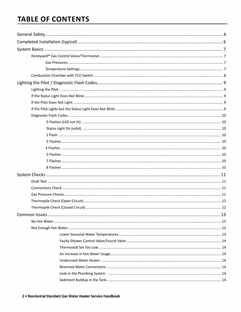
TABLE OF CONTENTS
General Safety .................................................................................................................................................... 4Completed Installation (typical) ......................................................................................................................... 6System Basics ..................................................................................................................................................... 7
Honeywell® Gas Control Valve/Thermostat ............................................................................................................................ 7
Gas Pressures ............................................................................................................................................................ 7
Temperature Settings ................................................................................................................................................ 7
Combustion Chamber with TCO Switch .................................................................................................................................. 8
Lighting the Pilot / Diagnostic Flash Codes ......................................................................................................... 9Lighting the Pilot: ................................................................................................................................................................... 9
If the Status Light Does Not Blink: ........................................................................................................................................... 9
If the Pilot Does Not Light: ...................................................................................................................................................... 9
If the Pilot Lights but the Status Light Does Not Blink: ............................................................................................................ 9
Diagnostic Flash Codes .......................................................................................................................................................... 10
0 Flashes (LED not lit) ............................................................................................................................................ 10
Status Light On (solid) ........................................................................................................................................... 10
1 Flash ................................................................................................................................................................... 10
2 Flashes ................................................................................................................................................................ 10
4 Flashes ................................................................................................................................................................ 10
5 Flashes ................................................................................................................................................................ 10
7 Flashes ................................................................................................................................................................ 10
8 Flashes ................................................................................................................................................................ 10
System Checks .................................................................................................................................................. 11Draft Test .............................................................................................................................................................................. 11
Connections Check ................................................................................................................................................................ 11
Gas Pressure Checks .............................................................................................................................................................. 11
Thermopile Check (Open Circuit) .......................................................................................................................................... 12
Thermopile Check (Closed Circuit) ........................................................................................................................................ 12
Common Issues ................................................................................................................................................ 13No Hot Water ........................................................................................................................................................................ 13
Not Enough Hot Water .......................................................................................................................................................... 13
Lower Seasonal Water Temperatures ....................................................................................................... 13
Faulty Shower Control Valve/Faucet Valve ............................................................................................... 14
Thermostat Set Too Low ........................................................................................................................... 14
An Increase in Hot Water Usage ............................................................................................................... 14
Undersized Water Heater ......................................................................................................................... 14
Reversed Water Connections ................................................................................................................... 14
Leak in the Plumbing System ................................................................................................................. 14
Sediment Buildup in the Tank ................................................................................................................... 14

Residential Standard Gas Water Heater Service Handbook • 3
BASI
CS
Residential Standard Gas Water Heater Service Handbook • 3
BASI
CS
Residential Standard Gas Water Heater Service Handbook • 3
Tank Leak ............................................................................................................................................................................... 15
Condensation .......................................................................................................................................................... 15
Leaking Plumbing Connections ............................................................................................................................... 15
Drips from the T&P Relief Valve Discharge Pipe ..................................................................................................... 15
Temperature Too High ........................................................................................................................................................... 16
Low Water Pressure .............................................................................................................................................................. 16
Water Odor ........................................................................................................................................................................... 16
Service Procedures ........................................................................................................................................... 17Removing the Manifold/Burner Assembly ............................................................................................................................ 17
Removing the Burner from the Manifold/Burner Assembly ................................................................................................. 17
Replacing the Pilot/Thermopile Assembly ............................................................................................................................ 17
External Inspection and Cleaning of the Base-Ring Filter ..................................................................................................... 18
Cleaning the Combustion Chamber and Flame Arrestor....................................................................................................... 18
Replacing the Manifold/Burner Assembly ............................................................................................................................ 19
Testing the Igniter System ..................................................................................................................................................... 19
Removing and Replacing the Gas Control Valve/Thermostat ................................................................................................ 20
Removing the Gas Control Valve/Thermostat: ........................................................................................................ 20
Replacing the Gas Control Valve/Thermostat: ........................................................................................................ 20
Draining and Flushing ............................................................................................................................................................ 20
Supplements..................................................................................................................................................... 21Evaluating Combustion and Ventilation Air Supply ............................................................................................................... 21
Attic Installations .................................................................................................................................................................. 23
Overview ................................................................................................................................................................. 23
Pilot Outage ............................................................................................................................................................ 23
Elevated Air Temperature: ........................................................................................................................ 24
Insufficient Makeup Air ............................................................................................................................ 24
Blocked Air Screen or Flame Arrestor ....................................................................................................... 24
Improper Venting of the Water Heater .................................................................................................... 24
Decompression ........................................................................................................................................ 25
Wind ........................................................................................................................................................ 25
Water Damage ........................................................................................................................................................ 25
Elevated Water Temperature .................................................................................................................................. 25
Field Installation of Draft Hoods ........................................................................................................................................... 26
Tools and Materials ................................................................................................................................................. 26
Types of Draft Hoods Covered in this Section ......................................................................................................... 26
Types of Vent Pipe Covered in this Section ............................................................................................................. 27
Installation Procedure ............................................................................................................................................. 27
Coupling .................................................................................................................................................................. 27
Type B Draft Hood Connectors ................................................................................................................................ 28

4 • Residential Standard Gas Water Heater Service Handbook
BASI
CS
4 • Residential Standard Gas Water Heater Service Handbook
BASI
CSGENERAL SAFETY
Your safety and the safety of others is extremely important in the servicing of this water heater. Many safety-related messages and instructions have been provided in this handbook and on your water heater to warn you and others of a potential hazard. Read and obey all safety messages and instructions throughout this handbook as well as those found in the Installation Instructions/Use & Care Guide.
It is very important that the meaning of each safety message is understood by you and others who service this water heater. The information contained in this handbook is designed to answer commonly faced situations encountered in the operation of the standard Residential Gas product line and is not meant to be all-inclusive. If you are experiencing a problem not covered in this handbook, please contact the Technical Information Center listed on the back cover of this handbook for further assistance. Additional information is also available on the web site listed on the back cover of this handbook.
This handbook is intended for use by licensed plumbing professionals and reference should be made to the Installation Instructions and Use & Care Guide accompanying the product. This handbook contains supplemental information to the Installation Instructions and Use & Care Guide.
When servicing residential water heaters, it is essential that you return the unit to a safe condition before you leave the site. All original components must be re-installed and all safety measures must be implemented. In addition, the recommended water temperature setting is 120° F.
IMPORTANT: It is recommended that on every service call, an inspection & cleaning of the base ring filter and flame arrestor be performed. See page 18.
Tools Required (for servicing gas models):
• Phillips head screw driver
• 3/8, 7/16, & 3/4 inch open end wrenches
• 3/16 inch Allen wrench
• 1-1/16 inch – 6 point – socket – for anode removal
• Electrical multimeter (with alligator leads)
• Digital or analog manometer
• Gas pressure gauge
• Water pressure gauge
• Thermometer
• Hose – to drain tank
• Container – to measure gallons per minute flow Digital Manometer

Residential Standard Gas Water Heater Service Handbook • 5
BASI
CS
Residential Standard Gas Water Heater Service Handbook • 5
BASI
CS
Fire or Explosion HarzardDo not store or use gasoline or other flammable vapors andliquids in the vicinity of this or any other appliance. Avoid all ignition sources if you smell Natural or LP gas.Do not expose water heater control to excessive gaspressure.Use only gas shown on rating plate.Maintain required clearances to combustibles.Keep ignition sources away from faucets after extendedperiod of non-use.
Read instruction manual beforeinstalling, using or servicing
water heater.
Fire or Explosion HarzardHydrogen gas can be produced in a hot water system after a period of non-use (generally two or more weeks).Hydrogen gas is extremely flammable and can ignite.To return hot water system to service, open a hot water faucet in kitchen for several minutes before using electrical appliances.Do not smoke or have open flame near faucet while it is open.Leave hot water faucet open until the sound of escaping air stops.
After extended period of non-use, purge gases from hot water system.

6 • Residential Standard Gas Water Heater Service Handbook
BASI
CS
6 • Residential Standard Gas Water Heater Service Handbook
BASI
CSCOMPLETED INSTALLATION TYPICAL
Exhaust Vent toOuside of Building
Union
Union
Water Shut-Off
Valve
Water Supply- Cold*
Expansion Tank Pressurized to Equal
Supply Water Pressure*(Relieve water pressure on the expansion tank
before adjusting air pressure.)
Temperature-Pressure Relief Valve with discharge piped to an
adequate drain. Do not cap or plug.
6” Maximum Air GapNOTE: Local codes
may vary.
Drain
Gas Control Valve/ThermostatRecommended setting of 120°F.
Metal Drain Pan piped to an adequate drain.NOTE: Drain pan diameter must be at least 2 inches wider than the diameter of the water heater.
Sediment Trap3” Minimum.
Gas Supply
To Fixtures - Hot
The water heater must be installed according to all local and state codes or in the absence of local and state codes, the “National Fuel Gas Code” ANSI Z223.1(NFPA 54)- current edition.
See Labels and Installation Instructions and Use & Care Guidefor clearances.
* NOTE: If on a well system, the expansion tank should be set to the maximum pressure of the pump tank.
*Massachusett: Installa vacuum relief in coldwater line per section19 MGL 142.
Do not cap or plug.
Union
Manual GasShut-off Valve
UntemperedHot Water
Tempered WaterTo Fixtures
ColdWaterInlet
HotWaterOutlet
Mixing Valve(Set to 120°F)
Follow the MixingValve Manufacturer’s
Instructions
Base Ring Filter:Air is drawn in for combustion. Keep area clean and free from flammables and flammable vapors.
Figure 1.

Residential Standard Gas Water Heater Service Handbook • 7
BASI
CS
Honeywell® Gas Control Valve/ThermostatWater heaters covered by this handbook are equipped with Honeywell gas control valve/thermostats.
• The Honeywell valve uses a thermopile instead of a thermocouple as did previous designs.
• Heat on the thermopile generates 750 to 900 millivolts (open circuit).
• When heated by the pilot and connected to the Honeywell control, the thermopile generates at least 350 millivolts (closed circuit). This voltage opens the power head in the control, allowing gas to flow. It also powers the onboard diagnostics (status light). See Figure 2.
• The Honeywell valve uses a standard push-button piezo igniter. See “Spark Igniter” in Figure 2B.
• Status codes are printed on the face of the control for easy reference (Figure 2B.)
• The LED status light shows the current status of the control as well as possible error codes for easy diagnosis. For more information on
error codes, see “Lighting the Pilot / Diagnostic Flash Codes” on page 9.
Thermopile
Pilot
Figure 2.
Gas PressuresEnsure that the following pressures are observed and maintained:
Table 1. GAS PRESSURESGAS MAXIMUM
SUPPLY PRESSURE
MANIFOLD GAS
PRESSURE
NAT 14 InWC 5.0 InWC (± 0.4 InWC)
LP 14 InWC 10.0 InWC(± 0.5 InWC)
Min. Supply Pressure: See Rating Plate.
The gas control valve\thermostat also includes a temperature limiting ECO (Energy Cut Off) system. This system will shut off the water heater if the water temperature becomes excessive. Should the water temperature get too high, the main burner and pilot will shut off automatically. Once the pilot is relit, the status light will flash a code (4 flashes), indicating an over-temperature condition. See “Lighting the Pilot / Diagnostic Flash Codes” on page 9 for more information.
NOTE: Honeywell is a registered trademark of Honeywell International, Inc.
Temperature Se ngsThe water temperature setting can be adjusted from 55°F to 155°F. Simply turn the gas control/temperature Knob to the desired setting/temperature. See Figure 3.
NOTE: The temperatures indicated are approximates. The actual temperature of the heated water may vary.
SYSTEM BASICS
Figure 2B
Temperature Control Knob*
Temperature control ranges:
* Some models do not
8 • Residential Standard Gas Water Heater Service Handbook
BASI
CS
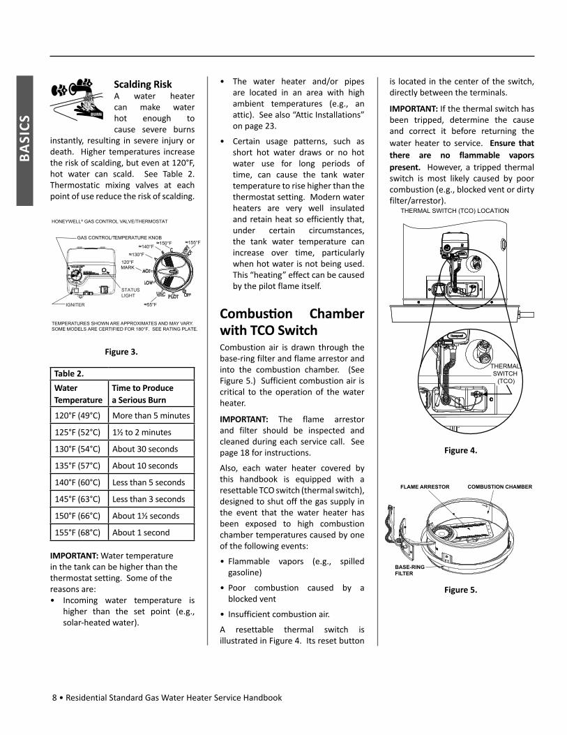
Scalding RiskA water heater can make water hot enough to cause severe burns
instantly, resulting in severe injury or death. Higher temperatures increase the risk of scalding, but even at 120°F, hot water can scald. See Table 2. Thermostatic mixing valves at each point of use reduce the risk of scalding.
VAC
HONEYWELL® GAS CONTROL VALVE/THERMOSTAT
GAS CONTROL/TEMPERATURE KNOB
120°FMARK
130°F
140°F150°F 155°F
55°F
TEMPERATURES SHOWN ARE APPROXIMATES AND MAY VARY.SOME MODELS ARE CERTIFIED FOR 180°F. SEE RATING PLATE.
STATUSLIGHT
IGNITER
Figure 3.
Table 2.
Water Temperature
Time to Produce a Serious Burn
120°F (49°C) More than 5 minutes
125°F (52°C) 1½ to 2 minutes
130°F (54°C) About 30 seconds
135°F (57°C) About 10 seconds
140°F (60°C) Less than 5 seconds
145°F (63°C) Less than 3 seconds
150°F (66°C) About 1½ seconds
155°F (68°C) About 1 second
IMPORTANT: Water temperature in the tank can be higher than the thermostat setting. Some of the reasons are:• Incoming water temperature is
higher than the set point (e.g., solar-heated water).
• The water heater and/or pipes are located in an area with high ambient temperatures (e.g., an attic). See also “Attic Installations” on page 23.
• Certain usage patterns, such as short hot water draws or no hot water use for long periods of time, can cause the tank water temperature to rise higher than the thermostat setting. Modern water heaters are very well insulated and retain heat so efficiently that, under certain circumstances, the tank water temperature can increase over time, particularly when hot water is not being used. This “heating” effect can be caused by the pilot flame itself.
Combus on Chamber with TCO SwitchCombustion air is drawn through the base-ring filter and flame arrestor and into the combustion chamber. (See Figure 5.) Sufficient combustion air is critical to the operation of the water heater.
IMPORTANT: The flame arrestor and filter should be inspected and cleaned during each service call. See page 18 for instructions.
Also, each water heater covered by this handbook is equipped with a resettable TCO switch (thermal switch), designed to shut off the gas supply in the event that the water heater has been exposed to high combustion chamber temperatures caused by one of the following events:
• Flammable vapors (e.g., spilled gasoline)
• Poor combustion caused by a blocked vent
• Insufficient combustion air.
A resettable thermal switch is illustrated in Figure 4. Its reset button
is located in the center of the switch, directly between the terminals.
IMPORTANT: If the thermal switch has been tripped, determine the cause and correct it before returning the water heater to service. Ensure that there are no flammable vapors present. However, a tripped thermal switch is most likely caused by poor combustion (e.g., blocked vent or dirty filter/arrestor).
THERMAL SWITCH
(TCO)
THERMAL SWITCH (TCO) LOCATION
Figure 4.
Figure 5.
FLAME ARRESTOR COMBUSTION CHAMBER
BASE-RINGFILTER

Residential Standard Gas Water Heater Service Handbook • 9
PILO
T/FL
ASH
CO
DES
LIGHTING THE PILOT / DIAGNOSTIC FLASH CODES
Ligh ng the Pilot: 1. Read and follow the lighting
instructions on the water heater’s label.
2. Turn the control knob to “Pilot.” Press the knob in fully and hold it in. (The knob will travel in about 1/4-inch if it is set to Pilot correctly.)
3. While holding the control knob in, click the igniter button continuously for up to 90 seconds or until the Status Light begins to blink.
If the status light does not begin to blink after 90 seconds, STOP. Release the control knob. Wait 10 minutes before attempting to relight the Pilot. Repeat these steps 2-3 times, if necessary.
The circuitry in this gas valve requires that you wait 10 minutes between lighting attempts.
If the Status Light blinks, release the gas control/temperature knob and turn it to the desired setting. (“Hot” is approximately 120°F).
Figure 6.
If the Status Light Does Not Blink:1. Wait 10 minutes before another
lighting attempt.
2. If the status light did not blink, repeat the lighting procedure by following the lighting instructions on the water heater’s label. Remove the outer
door. The control knob must be set to Pilot and held in continuously while clicking the igniter button (about once per second for up to 90 seconds). To observe the Pilot, remove the outer door and look through the view port (sight glass). See Figure 7.
3. Continue clicking the Igniter button (for up to 90 seconds) until pilot lights.
4. Once the pilot is lit, continue to hold the control knob in until the Status Light begins to blink.
5. Release control Knob and set Knob to desired temperature setting. (“Hot” is approximately 120°F.)
6. Replace the outer door.
If the Pilot Does Not Light:1. Wait 10 minutes before another
lighting attempt. If the pilot does not light, the Igniter may not be sparking or the unit may not be getting gas (or for a new installation, there may still be air in the gas line). Each time you click the igniter button, you should be able to see the spark by looking through the view port. See Figure 7. (You may have to darken the room lights to see the spark.) You do not have to push the Control Knob in to check the Igniter button. Simply look through the sight glass while clicking the Igniter button and look for a spark. If you can’t see a spark when the Igniter button is clicked, check the wiring connections from the Igniter button and make sure that they are tight.
2. If you see the igniter spark, try relighting the pilot by following the instructions on the water heater’s label. Ensure that the gas supply is turned on. There may be air in the gas line, and several lighting attempts
may be needed to completely fill the line with gas and successfully light the pilot.
VAC
THERMAL SWITCH
V
V TAT
Figure 7.
If the Pilot Lights but the Status Light Does Not Blink:1. If the pilot lights, continue to hold the
control knob in until the status light blinks. If the pilot is lit and remains lit for 90 seconds and the Status Light still does not blink, the thermopile connections may be loose, the thermal switch may need to be reset, or the thermopile may be defective.
2. Remove the outer door.
3. Press the reset button on the thermal switch (TCO switch). See Figure 7.
4. If the switch clicks, it may have tripped. Do not light the pilot if flammable vapors are present. Check flame arrestor for signs of discoloration (which could be caused by flammable vapors). If the flame arrestor is discolored, do not attempt to relight the Pilot. Have the water heater inspected by a qualified service technician.
5. Check the wiring connections from the thermopile and thermal switch (TCO) to the gas control valve/thermostat. Ensure that all wiring connections are tight. See Figure 7.
6. Replace the outer door.

10 • Residential Standard Gas Water Heater Service Handbook
PILO
T/FL
ASH
CODE
S
7. Wait 10 minutes and try to light the Pilot according to the instructions on the water heater’s label.
8. While clicking the igniter button continuously, the control knob must be set to Pilot and held in until the Status Light blinks. Once the status light blinks, release the control knob and set the knob to the desired temperature setting. (“Hot” is approximately 120°F.)
Diagnos c Flash CodesNOTE: In each case, the flash code will occur, followed by a 3 second pause, and then will repeat.
0 Flashes (LED not lit) Indication/Condition: Control Off/Pilot Out.
Check/Repair:
1. Follow the lighting instructions on the front of the water heater and attempt to relight the pilot. Confirm that the pilot is lit by looking through the viewport (Figure 16, p. 17).
2. If pilot will light but does not hold, check for a tripped thermal switch. (Measure continuity by placing a meter lead on each of the two terminals. Continuity means that it was not tripped.) If thermal switch is tripped, check for flammable vapors in the area and ensure that the unit has adequate combustion air and proper draft before relighting. (You can reset the thermal switch by pressing the reset button in its center.) Also, ensure that the filter and flame arrestor are clean (p. 18).
3. If the pilot will light and does hold, record any status codes and follow the procedures relating to that code.
4. If pilot will not light at all, verify the piezo igniter is producing a spark and the unit is getting the correct supply gas pressure. See “Testing
the Igniter System” (p. 19); “Gas Pressure Checks” (p. 11). Also, check the thermopile wiring connections (Figure 16, p. 17).
Status Light On (solid) Indication/Condition: Pilot light was recently extinguished and the thermopile is cooling down.
Check/Repair:
1. Turn the gas control valve/thermostat knob to OFF.
2. Wait 10 minutes for the thermopile to cool, then attempt to relight the pilot by following the lighting instructions on the water heater’s label. NOTE: This gas control valve/thermostat has built-in circuitry that requires waiting 10 minutes between lighting attempts.
Until the Thermopile reaches its normal operating temperature, the status light will not blink, even if the pilot is lit. It may take up to 90 seconds of continuous pilot operation before the thermopile reaches normal operating temperature and the Status Light starts to blink.
1 Flash Indication/Condition: Normal Operation (bright/dim heartbeat)
Check/Repair: No corrective action necessary.
2 Flashes Indication/Condition: Thermopile voltage low.
Check/Repair:
1. Check all wiring connections for loose or damaged wires. Correct if needed.
2. Check the millivolt output on the thermopile. If output is less than 350 millivolts DC, replace the thermopile.
See also “Condensation” on page 15.
4 Flashes Indication/Condition: Temperature exceeded (ECO activated).
Check/Repair:
1. Turn gas control valve/thermostat knob to OFF.
2. Turn the main gas supply OFF.
3. Replace the gas control valve/thermostat.
5 Flashes Indication/Condition: Sensor failure.
Check/Repair:
1. Turn gas control valve/thermostat knob to OFF.
2. Turn the main gas supply OFF.
3. Replace the gas control valve/thermostat.
7 Flashes Indication/Condition: Internal control failure.
Check/Repair:
1. Turn gas control valve/thermostat knob to OFF.
2. Turn the main gas supply OFF.
3. Replace the gas control valve/thermostat.
8 Flashes Indication/Condition: Power off failure.
Check/Repair:
1. If the pilot flame is present when the control knob is set to the OFF position, replace the gas control valve/thermostat.
2. If the pilot flame is not present when the control knob is set to the OFF position, wait 10 minutes for the thermopile to cool, then relight the unit. If this condition returns, replace the gas control valve/thermostat.

Residential Standard Gas Water Heater Service Handbook • 11
SYST
EM C
HEC
KS
SYSTEM CHECKS
Explosion RiskWARNING! Before performing any
test, check the area around the water heater for any source of a flammable vapor (i.e gasoline, paint thinners, etc.). If any sources are found, do not proceed until they are removed.
Dra Test WARNING! Burn Hazard. Do not
touch the vent. Doing so can cause burns.
After successfully lighting the water heater, allow the main burner to operate for five minutes. Close all windows and doors and turn on all gas appliances and air-moving devices (range hoods, bathroom exhaust fans, ceiling fans, etc.) in the home. Also, close any fi replace dampers.
After five minutes, pass a newly ex nguished match about one inch (1”) from the dra hood’s relief opening. Smoke from the match should be steadily drawn into the opening, indica ng proper dra and a func oning vent system.
MATCH
DRAFT HOOD
RELIEF OPENING
Figure 8.
If the main burner has been opera ng for fi ve minutes, but the match smoke dri s around or is blown away from the opening, turn the gas control knob OFF. Do not operate the water heater until proper adjustments or repairs are made to the vent pipe system and/or air supply (p. 21). Always check the filter and flame arrestor first and clean them, if necessary (p. 18).
Connec ons CheckSome issues can be caused by faulty connections. Refer to the following list of connections when troubleshooting the system:
• Igniter wire (Figure 9). See also “Testing the Igniter System” on page 19.
• Thermopile/thermal switch wires at the gas control valve/thermostat (Figure 9).
• Wire connections at the thermal switch (TCO). A disconnected thermal switch wire can cause the pilot to become inoperable. See Figure 4, page 8.
See also “Diagnostic Flash Codes” on page 10.
Igniter Wire
From Thermopile (White)
From Thermal Switch (Red)
Manifold Pressure Tap
(1/8” NPT-RH) Manifold Flex Tube Nut:
Figure 9.
Gas Pressure ChecksGas pressure checks are made with flowing gas. Use a gas pressure gauge capable of reading pressure in inches of water column.
• Supply gas pressure checks are measured before the gas control valve/thermostat and as close to the water heater as possible. NOTE: The dynamic gas pressure (burner on) should be measured with all appliances operating that use the common gas supply.
• Manifold (main burner) gas pressure is measured at the pressure tap on the bottom of the gas control valve/thermostat. See Figure 9 and Figure 11. Use a 3/16” Allen wrench to remove the pressure tap plug, then attach the gas gauge.
NOTE: Gas outlet pressures will be listed on the gas control valve/thermostat’s pressure label. See Figure 10. Also, gas supply pressure requirements are shown on the water heater labeling.
VAC
GAS PRESSURE
GAUGE
CONNECTED ATPRESSURE TAP
MANIFOLD GAS PRESSURE TEST
GAS PRESSURE LABEL (OUTLET PRESSURE)
Figure 10.
CONNECTED AT PRESSURE TAP
Figure 11.

12 • Residential Standard Gas Water Service Handbook
SYST
EM C
HEC
KS
Table 3.
Gas Pressures
IF . . .. . . THEN
...the supply gas pressure is lower than required...
• increase the supply gas pressure regulator setting
and/or
• increase supply gas piping size.
...the supply gas pressure is higher than required...
• add a gas pressure regulator.
• reduce the setting on the existing regulator.
...the manifold gas pressure is not within +/- 10% of the value shown on the gas pressure label...
• ensure that there is adequate supply gas pressure
• ensure that the main burner orifice is the correct size for the model being tested.
• if the above tests have been performed and the results were correct, replace the gas control valve (p. 20).
NOTE: The gas pressure label lists the gas valve outlet pressure. This is the same as the manifold pressure. See Figure 10.
Thermopile Check (Open Circuit)The following test will check the DC voltage generated by the thermopile when the pilot light is lit.
1. Remove the connectors from the gas control valve/thermostat (red and white wires). Use needle-nose pliers.
2. Insert multimeter leads into the connectors. The multimeter must be set to read millivolts DC (on a scale that can read 750 millivolts). Reference Figure 12.
USE A MULTIMETER TO CHECK THE OUTPUT OF THE THERMOPILE (MEASURED IN MILLIVOLTS).
SHOWN ABOVE - MULTIMETER PROBES ARE INSERTED INTO THE THERMOPILE PLUGS. THESE PLUGS WERE REMOVED FROM THE RECEPTACLE AT THE BOTTOM, RIGHT-HAND CORNER OF THE GAS CONTROL VALVE/ THERMOSTAT.
Figure 12.
3. Follow the lighting instructions to light the pilot. Once the pilot is lit, continue to hold the gas control knob in until this test is complete. You may need assistance from another person to do this. The voltage reading should rise gradually as the thermopile heats up. After a few minutes, you should have a reading of at least 350 mV DC. A reading above 350 mV DC indicates that the thermopile is working properly.
4. When you are finished, plug the connectors back into the gas control valve/thermostat. If the connectors are separate (not a double connector), ensure that the red wire connector is to the left and the white wire connector is to the right. See Figure 2B, page 7. If the status light does not blink once every three seconds, replace the gas control valve/thermostat.
Thermopile Check (Closed Circuit)Follow the lighting instructions to light the pilot. Once the pilot is lit, you can check the output of the thermopile with one of the following tests. A reading above 350 mV DC indicates that the thermopile is working properly.
INSERT MULTIMETER LEADS INTO THERMOPILE PLUGS AT CONTROL.PILOT MUST BE LIT.
MULTIMETER SET TO READ mV.
MINIMUM ACCEPTABLE MEASUREMENT: 350 mV DC.
Figure 13.
INSERT ONE MULTIMETER LEAD INTO THE NEGATIVE PLUG ON THE CONTROL (WHITE WIRE).
TOUCH THE OTHER LEAD TO A TERMINAL ON THE THERMAL SWITCH (TCO).
MULTIMETER SET TO READ mV.PILOT MUST BE LIT. MINIMUM ACCEPTABLE MEASUREMENT: 350 mV DC.
Figure 14.

Residential Standard Gas Water Heater Service Handbook • 13
COM
MO
N IS
SUES
Fire and Explosion Hazard
WARNING! Do not attempt to light the water
heater if flammable vapors or liquids are present. Do not store or use gasoline or other flammable vapors and liquids in the vicinity of this or any other gas appliance. Storage of or use of gasoline or other flammable vapors or liquids in the vicinity of this or any other appliance can result in serious injury or death.
No Hot WaterIf water is not being heated, check the following:
1. Look at the gas control valve/thermostat. Is it flashing? If so, solutions for restoring hot water are listed below. See also “Diagnostic Flash Codes” on page 10.
1 Flash Normal Operation(This code may occur after you relight the pilot.) Once the water heater has completed a heating cycle, it should provide an adequate amount of hot water. If it does not, see “Not Enough Hot Water.” If the pilot lights for a while, then goes out, see “0 Flashes (LED not lit)” on page 10.
2 Flashes Thermopile voltage is lowPossible causes/solutions:• Thermopile is getting weak.• Check wiring and connections.• If necessary, replace the
thermopile. See “Replacing the Pilot/Thermopile Assembly” on page 17.
4, 5, or 7 FlashesIf you observe one of these flash codes, refer to “Diagnostic Flash Codes” on page 10.
8 FlashesPower Off FailureOften, this error can be cleared by turning the pilot off, letting it cool down for ten minutes, then relighting it according to the lighting instructions. See “8 Flashes” on page 10.
2. If the status light is not lit, see “0 Flashes (LED not lit),” page 10. That section will help you investigate causes related to the thermal switch (TCO), spark ignition, gas pressures, and thermopile connections.
NOTE: The pilot must be lit for the status light (LED) to flash. Heat from the pilot causes the thermopile to generate voltage. Without this voltage, the gas control valve/thermostat cannot operate. Remember: it may take up to 90 seconds to heat the thermopile enough to power the status light.
3. If you completed step 2 and the pilot will not light, check for air in the gas line. (This is fairly common with recent work/new installations.) If there is air in the gas line, bleed the line as necessary. Make sure to hold the gas control knob in fully and hold it in. In most cases, energy efficient pilot orifices are so small that it may be difficult to clear the air by holding the knob in.
When you are finished, try to light the pilot. (Follow the lighting instructions on the water heater.) Remember to hold the control knob in for at least 90 seconds so the pilot can heat up.
Did the pilot light? If it did, check the following:
A. If the pilot did not light, replace the pilot. (The entire pilot/thermopile assembly must be
replaced). The most likely cause is contamination in the pilot tube.
A. If the pilot is lit and the status light is flashing, refer to “Diagnostic Flash Codes” on page 10.
B. If the pilot is lit, but the status light did not start flashing, check the thermopile (p. 12). If its output is 350 mV or less, it must be replaced. If its output is greater than 350 mV, replace the gas control valve/thermostat.
Not Enough Hot WaterCheck the following if the water is not hot enough or if the hot water runs out too quickly:
Possible causes
• Lower seasonal water temperatures• Faulty shower control or faucet
valve• Thermostat is set too low
• Increased hot water usage
• Water heater is too small to meet demand
• Reversed plumbing connections
• Plumbing system leak
• Sediment buildup in the tank
Verify the water temperature at the temperature/pressure relief valve. Check the mixing valve/shower control settings. Also check for leaks, heavy usage, and extremely cold incoming water. In all cases, clean the filter and flame arrestor (p. 18), then conduct a draft test (p. 11).
A description of each cause and its solution(s) is listed below.
Lower Seasonal Water Temperatures
In some areas, water coming into the tank is much colder during winter
COMMON ISSUES

14 • Residential Standard Gas Water Service Handbook
COM
MO
N IS
SUES
and early spring months. Even when the water heater is working properly, it may take longer to fully heat the water. As a result, hot water may not be available as quickly as it is during warmer months.
Faulty Shower Control Valve/Faucet Valve
Check the hot water at all faucets in the home. Some may have built-in thermostat or pressure-balance mixing valves that may need adjustment or replacement. If you get hot water from some outlets but not others, adjust/replace each fixture as necessary.NOTE: A mixing valve issue is not a water heater defect and is not covered by the water heater warranty.
Thermostat Set Too Low
Scalding RiskA water heater can make water hot enough to cause
severe burns instantly, resulting in severe injury or death. Higher temperatures increase the risk of scalding, but even at 120°F, hot water can scald. See Table 2 on page 8 before proceeding. Thermostatic mixing valves at each point of use reduce the risk of scalding.
If you’ve checked all of the faucets and shower controls and the water temperature is still too cool, the water heater’s thermostat may be set too low. See “Temperature Settings” on page 7 for instructions on how
to adjust the thermostat. If there still isn’t enough hot water, set the thermostat to a higher setting and install a thermostatic mixing valve at each point of use.
An Increase in Hot Water Usage
If hot water is running out during holidays, weekends, or family gatherings, the demand for hot water may be exceeding the water heater’s capacity. Hot water usage can be reduced by washing clothes in cold water, installing flow restrictors on shower heads, and taking other conservation steps.
Undersized Water Heater
If water is frequently too cool, the water heater may be too small. If the water heater is old, the best solution may be to replace it with a larger model. If the water heater is in good condition, you may set the thermostat to a temperature above 120°F and install thermostatic mixing valves at each point of use. Set each thermostatic mixing valve’s delivery temperature to 120°F to reduce the risk of scalding. (See “Temperature Settings” on page 7.)
This method can increase the effective size of the water heater by about 30%.
Reversed Water Connec ons
If the hot and cold water connections are reversed, it may appear as if the water heater isn’t producing much hot water. This problem is usually identified at the time of installation.
Confirm that the home’s hot water pipe is connected to the water heater’s hot water outlet, not the cold water inlet. If the connections are reversed, switch them to the correct position.
NOTE: The water heater’s hot water outlet will be marked with an “H” or “HOT,” or will be color coded red.
Leak in the Plumbing System
A leak in the home’s plumbing system can overload the water heater’s ability to heat water. In that case, the water heater can be working, but there will be little or no hot water. Check the plumbing system for leaks and repair as necessary.
Sediment Buildup in the Tank
If the water heater is several years old and/or is installed in an area known for hard water, there may be a buildup of sediment at the bottom of the tank. Sediment buildup may reduce the efficiency of the water heater and may reduce the amount of available hot water.
Drain and flush the tank (page 20). You may also treat the tank with a lime/scale removal solution that is approved for potable water heaters.

Residential Standard Gas Water Heater Service Handbook • 15
COM
MO
N IS
SUES
Tank Leak Condensa onIf you see small puddles of water in the drain pan or hear sizzling sounds as water drips on the burner, the water heater may be producing condensation. Condensation may drip onto the burner or other hot surfaces to produce a sizzling sound. On some models, this may actually cause the pilot to go out.
Condensation usually occurs when the water heater tank is full of cold water. Condensation will most likely occur:
• During holidays, weekends, or family gatherings when there is an increase in your home’s hot water usage.
• During the winter and early spring months when incoming water temperatures are at their lowest.
• If the water heater is a new installation.
• If a large amount of hot water is used in a short period of time.
• If the water heater is too small for the home’s hot water demands.
In most cases, condensation should disappear once the water heater reaches normal operating temperature, or when the home’s hot water demands return to normal.
If the water heater is too small for the home’s typical hot water demands, the water heater may produce
condensation regularly. In that case, a larger water heater is recommended.
NOTE: Condensation may cause a “2 Flashes” error code, indicating low thermopile voltage. This condition may clear up as the tank begins to warm. See “2 Flashes” on page 10
Leaking Plumbing Connec onsIf there’s water on the floor around the bottom of the water heater, check the plumbing connections on top of the tank. Use a dry paper towel to wipe around the hot and cold pipe connections on top of the water heater. If the paper towel is wet after wiping a connection, repair the leak(s).
Drips from the T&P Relief Valve Discharge PipeA small amount of water dripping from the temperature and pressure (T&P) relief valve usually means the home’s water pressure is too high or you need a properly sized and pressurized thermal expansion tank. A large amount of hot water coming from the T&P discharge pipe may be due to the tank overheating.
WARNING! Do not cap or plug the T&P relief valve or discharge pipe, and do not operate the water heater without a functioning T&P relief Valve. This could cause an explosion.
Refer to Figure 1 on page 6 while reviewing this section.
• Water pressure too high. High water pressure can cause the T&P relief valve to drip. Install a pressure reducing valve (PRV) on the main cold water supply line. Adjust the PRV to between 50 and 60 psi.
• Thermal Expansion Tank. Install a Thermal Expansion Tank. If a Thermal Expansion Tank is already installed and the T&P Relief Valve discharge pipe drips, the Thermal Expansion Tank may be pressurized to the wrong pressure or the internal bladder may be defective. Refer to the instructions that came with the Thermal Expansion Tank for more information.
• Debris. In rare cases, debris can stick inside the T&P relief valve preventing the valve from seating fully. In that case, the T&P relief valve discharge pipe will drip. You may be able to clear debris from the T&P Relief Valve by manually operating the valve, allowing small quantities of water to flush out the debris. See the label on the T&P relief valve for instructions.
If the water pressure is between 50 and 60 psi, a thermal expansion tank is installed and properly pressurized, and the valve has been cleared of any debris, and it still drips, the valve may be broken. Install a new T&P relief valve.

16 • Residential Standard Gas Water Service Handbook
COM
MO
N IS
SUES
Temperature Too HighScalding RiskA water heater can make water hot enough to cause
severe burns instantly, resulting in severe injury or death. Higher temperatures increase the risk of scalding, but even at 120°F, hot water can scald. See Table 2 on page 8 before proceeding. Thermostatic mixing valves at each point of use reduce the risk of scalding.
If the water temperature is too hot:
• Install or adjust the thermostatic mixing valves for each point-of-use (see manufacturer’s instructions), or
• Adjust the temperature setting on the water heater. See “Temperature Settings” on page 7.
Low Water PressureCheck both the cold and hot water at a sink to determine if the lower pressure is only on the hot water side. If the low pressure is on the hot water side only, the primary causes of this are:
• Melted heat traps or dip tube. Soldering copper pipes while they are connected to the water heater can melt the heat traps inside the hot and cold water connections or the dip tube (cold water side). Melted heat traps or a melted dip tube can restrict the flow of hot water. If that’s the case, replace the heat traps or dip tube.
• Partially closed supply valve. Open the water heater’s supply valve fully.
Water OdorHarmless bacteria normally present in tap water can multiply in water heaters and give off a “rotten egg” smell. Although eliminating the bacteria that causes “smelly water” with a Chlorination system is the only sure treatment, in some cases, the standard anode rod that came with the water heater can be replaced with a special zinc anode rod which may help reduce or eliminate the odor. Contact Technical Assistance for availability.
NOTE: To protect the tank, an anode rod must be installed in the water heater at all times or the warranty is void.
In cases where the “rotten egg” smell is pronounced, you can raise the tank temperature to 140°F in order to reduce bacteria growth in the tank.
WARNING! Higher temperatures increase the risk of scalding. If you set the temperature setting higher than 120°F, thermostatic mixing valves at each point-of-use are particularly important. See “Temperature Settings” on page 7.

Residential Standard Gas Water Heater Service Handbook • 17
SERV
ICE
PRO
CED
URE
S
SERVICE PROCEDURES
Removing the Manifold/Burner Assembly1. Turn the gas control/temperature
knob to the “OFF” position (Figure 6 on page 9).
2. Before performing any maintenance, it is important to turn off the gas supply to the water heater at the manual gas shut-off valve (Figure 1, p. 6). This valve is typically located beside the water heater. Note the position of the shut-off valve in the open/on position, then proceed to turn it off.
3. With the unit shut-off, allow sufficient time for the water heater to cool before performing any maintenance.
IGNITERWIRE
RED WIRE TUBE
IGNITER
IGNITER
WIRE
WHITEWIRE
VAC
Figure 15.
4. Remove the outer door.
5. Disconnect the following from the gas control valve/thermostat: pilot tube (7/16” wrench), igniter wire (from the igniter lead wire), and manifold tube (3/4” wrench). See Figure 15.
6. Disconnect the white and red wires from the gas control valve/thermostat (Figure 15). Use needle nose pliers to grip the connector(s). IMPORTANT: Grip the connector carefully to prevent damage. Do not grip or pull the wires themselves.
7. Grasp the manifold tube and push down slightly to free the manifold tube and pilot tube.
8. Remove the screws (1/4” nut driver) securing the manifold/burner assembly to the combustion chamber. (Figure 16.)
9. Carefully remove the manifold/burner assembly from the combustion chamber. BE SURE NOT TO DAMAGE ANY INTERNAL PARTS.
VAC
THERMAL SWITCH
V
V TAT
Figure 16.
Removing the Burner from the Manifold/Burner AssemblyNatural Gas (Low Nox) & L.P. Gas Burner
1. Take off the burner by removing the two (2) screws located underneath the burner (Figure 17.).
2. Check the burner to see if it is dirty or clogged. The burner may be cleaned with soap and hot water. IMPORTANT: DO NOT remove the orifice.
BURNER (BOTTOM VIEW)
SCREWS (2)
PILOT ASSEMBLY(BOTTOM VIEW)
BURNER SCOOP(SOME MODELS)
MANIFOLD TUBE
Figure 17.
Replacing the Pilot/Thermopile AssemblyA. Removing the Old Pilot/
Thermopile Assembly from the Manifold Assembly
1. Remove the manifold door assembly as described in “Removing the Manifold/Burner Assembly” section.
2. Remove the burner to access the pilot/thermopile assembly. Remove and keep the screws securing the burner to the manifold (Figure 17.) IMPORTANT: DO NOT remove the orifice.
3. Remove the screw securing the pilot/thermopile assembly to the pilot bracket and keep for reuse later (Figure 18.)
4. Lift the retainer clip straight up from the back of the manifold component block (using a flat-blade screwdriver), then remove the manifold component block from the manifold door. See Figure 18. IMPORTANT: Be careful not to bend or alter the position of the pilot tube. It will be used as a bending template for the new pilot assembly. Note the placement/order of the wires in the manifold component block.
5. Lift the pilot/thermopile assembly (including the igniter wire) from the manifold assembly.
CONNECTORS
MANIFOLD COMPONENTBLOCK
PILOT TUBE
IGNITERWIRE
BURNER AND OTHER FITTINGS NOT SHOWFOR CLARITY.
MANIFOLD DOOR
RED WIRES TO
RETAINERCLIP
PILOT / THERMOPILE ASSEMBLY SCREW
Figure 18.

18 • Residential Standard Gas Water Heater Service Handbook
SERV
ICE
PRO
CED
URE
S
B. Installing the New Pilot/Thermopile Assembly
1. Read this step carefully before proceeding. Using the old pilot/pilot tube assembly as a guide, bend the new pilot tube to match the old one. Make only the bends closest to the pilot before going to the next step.
2. Route the new pilot tube and wires through the opening in the manifold door. See Figure 18 on page 17.PILOT/THERMOPILE ASSEMBLY
PILOT/THERMOPILEASSEMBLY
IGNITERCONNECTOR
THERMALSWITCHCONNECTORS
PILOT THERMOPILE
GAS CONTROL VALVE/
FOR CLARITY, PILOT TUBE NOT SHOWN .
Figure 19.
PILOT ASSEMBLY FOR CAST BURNER NOT SHOWN.
EXPLODED VIEW OF PILOT/THERMOPILE ASSEMBLY.FOR INFORMATIONAL PURPOSES ONLY. THE PILOT/THERMOPILE ASSEMBLY SHOULD BE INSTALLED/SERVICED AS A SINGLE UNIT. DO NOT DISASSEMBLE.
PILOTPILOT BRACKET
ORIFICE
PILOT TUBE
THESE TWO PARTS MAY BE COMBINED ON SOME MODELS.
THERMOPILE
Figure 20.
3. Using the pilot screw removed earlier, attach the new pilot/thermopile assembly. Reattach the burner to the manifold using the screws removed earlier. NOTE: If your burner includes a burner scoop, make sure that it is oriented to the pilot side of the manifold tube. See Figure 17 on page 17.
4. Reinstall the manifold component block in the manifold door. Ensure that the pilot tube and wires are positioned as shown in Figure 21.
5. Carefully bend the new pilot tube to match the bend of the manifold tube. NOTE: When bending, DO NOT crimp or crease the pilot tube.
6. Before you proceed to the next step, install the new brass ferrule nut in the gas control valve/thermostat’s pilot tube opening, HAND TIGHT ONLY.
7. Install the manifold/burner assembly.
RED THERMAL SWITCH WIRECONNECTIONS AT MANIFOLD DOOR
CONNECTS TO THE GAS CONTROLVALVE\THERMOSTAT.
WIRE CONNECTS TO THE GAS CONTROL VALVE\
THERMOSTAT.
THROUGH CENTER OF
BLOCK
MANIFOLD
BLOCK
Figure 21.
External Inspec on and Cleaning of the Base-Ring Filter1. At least annually, check the base-
ring filter for any dust or debris that may have accumulated on the filter screen. See Figure 22. NOTE: If the water heater is located in an area that is subjected to lint and dirt, it may be necessary to check the base-ring filter more frequently.
2. Follow the Lighting Instructions to turn off the water heater and allow it to cool for 10 minutes before attempting to clean the base-ring filter.
3. Use a vacuum cleaner with a hose attachment to remove any dust or debris that may have accumulated on the filter. NOTE: If you are unable to inspect or clean the base-ring filter, follow the “Cleaning the Combustion Chamber and Flame Arrestor” instructions.
4. After the base-ring filter has been cleaned, follow the Lighting Instructions to return the water heater to service.
DOOR GASKETFLAME ARRESTOR
COMBUSTION CHAMBER
BASE-RINGFILTER
Figure 22.
Cleaning the Combus on Chamber and Flame Arrestor1. Follow procedure outlined in
“Removing the Manifold/Burner Assembly.”
2. Use a vacuum cleaner/shop vac to remove all loose debris in the combustion chamber. See Figure 22. Use compressed air to clear any dust or debris that may have accumulated in the flame-arrestor. (To clean the flame arrestor, you may use a soft plastic brush under water heater. Vacuum lint from brush. Repeat until brush is clean.)
Residential Standard Gas Water Heater Service Handbook • 19
SERV
ICE
PRO
CED
URE
S
3. Reassemble following the procedure under “Replacing the Manifold/Burner Assembly.”
Replacing the Manifold/Burner Assembly
Explosion RiskWARNING!
• Tighten both manifold door screws securely.
• Remove any fiberglass between gasket and combustion chamber.
• Replace viewport if glass is missing or damaged.
• Replace manifold component block if it is missing or has been removed.
• Replace door gasket if it is damaged.
• Failure to follow these instructions can result in death, explosion, or fire.
1. Check the door gasket for damage or imbedded debris prior to installation. See Figure 22.
2. Inspect the viewport for damage and replace as required (Figure 16, page 17).
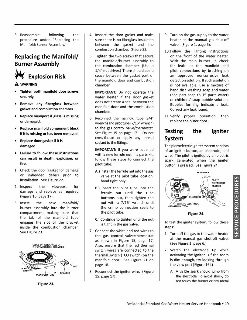
3. Insert the new manifold/burner assembly into the burner compartment, making sure that the tab of the manifold tube engages the slot of the bracket inside the combustion chamber. See Figure 23.
MANIFOLD TUBETIP BRACKET
SLOT
CLOSE-UP INSIDE VIEW OFTHE COMBUSTION CHAMBER.
Figure 23.
4. Inspect the door gasket and make sure there is no fiberglass insulation between the gasket and the combustion chamber. (Figure 22.)
5. Tighten the two screws that secure the manifold/burner assembly to the combustion chamber. (Use a 1/4” nut driver.) There should be no space between the gasket part of the manifold door and combustion chamber
IMPORTANT: Do not operate the water heater if the door gasket does not create a seal between the manifold door and the combustion chamber.
6. Reconnect the manifold tube (3/4” wrench) and pilot tube (7/16” wrench) to the gas control valve/thermostat. See Figure 15 on page 17. Do not cross-thread or apply any thread sealant to the fittings.
IMPORTANT: If you were supplied with a new ferrule nut in a parts kit, follow these steps to connect the pilot tube:
A.) Install the ferrule nut into the gas valve at the pilot tube location, hand tight only.
B.) Insert the pilot tube into the ferrule nut until the tube bottoms out, then tighten the nut with a 7/16” wrench until the crimp connection seals to the pilot tube.
C.) Continue to tighten until the nut is tight in the gas valve.
7. Connect the white and red wires to the gas control valve/thermostat as shown in Figure 15, page 17. Also, ensure that the red thermal switch wires are connected to the thermal switch (TCO switch) on the manifold door. See Figure 21 on page 18.
8. Reconnect the igniter wire. (Figure 15, page 17).
9. Turn on the gas supply to the water heater at the manual gas shut-off valve. (Figure 1, page 6).
10. Follow the lighting instructions on the front of the water heater. With the main burner lit, check for leaks at the manifold and pilot connections by brushing on an approved noncorrosive leak detection solution. If such a solution is not available, use a mixture of hand dish washing soap and water (one part soap to 15 parts water) or childrens’ soap bubble solution. Bubbles forming indicate a leak. Correct any leak found.
11. Verify proper operation, then replace the outer door.
Tes ng the Igniter SystemThe piezoelectric igniter system consists of an igniter button, an electrode, and wire. The pilot is ignited by an electric spark generated when the igniter button is pressed. See Figure 24.
VAC
PILOT/THERMOPILE BRACKET
ELECTRODE
THERMOPILE
PILOT
IGNITER BUTTONWIRE TO ELECTRODE
Figure 24.
To test the igniter system, follow these steps:
1. Turn off the gas to the water heater at the manual gas shut-off valve. (See Figure 1, page 6.)
2. Watch the electrode tip while activating the igniter. (If the room is dim enough, try looking through the view port [Figure 16].)
A. A visible spark should jump from the electrode. To avoid shock, do not touch the burner or any metal

20 • Residential Standard Gas Water Heater Service Handbook
SERV
ICE
PRO
CED
URE
S
part on the pilot or pilot assembly. If no spark is visible, check the wire connections and make sure that the electrode is not broken. See also “Connections Check” (p. 11).
B. Replace the igniter if defective (i.e., gas control valve/thermostat and/or pilot/thermopile assembly). Dirt and rust on the pilot or electrode tip can prevent the igniter spark. Wipe clean with a damp cloth and dry completely. Rust can be removed from the electrode tip and metal surfaces by lightly sanding with an emery cloth or fine grit sandpaper.
Removing and Replacing the Gas Control Valve/ThermostatIMPORTANT: This water heater has a resettable thermal switch installed. Do not attempt to disable or modify this feature in any way. Use only factory authorized replacement parts.
Removing the Gas Control Valve/Thermostat:1. Turn the gas control/temperature
knob to the “OFF” position. (Figure 6, page 9.)
2. Turn off the gas at the manual shut-off valve on the gas supply pipe. (Figure 1, page 6.)
3. Drain the water heater. Refer to the “Draining and Flushing” section and follow the procedure.
4. Disconnect the igniter wire from the igniter lead wire. Use needle nose pliers to disconnect the red (+) and white (-) thermopile wires. Disconnect the pilot tube (7/16” wrench) and manifold tube (3/4” wrench) at the gas control valve/thermostat. See Figure 15 on page 17.
5. Disconnect the ground joint union in the gas piping. See
Figure 1, page 6. Disconnect the remaining pipe from the gas control valve/thermostat.
6. To remove the gas control valve/thermostat, thread a 4” section of gas pipe into the inlet and use it to turn the gas control valve/thermostat (counterclockwise.) Do not use a pipe wrench or equivalent to grip body. Damage may result, causing leaks. Do not insert any sharp objects into the inlet or outlet connections. Damage to the gas control valve/thermostat may result.
Replacing the Gas Control Valve/Thermostat:To replace the gas control valve/thermostat, reassemble in reverse order. When replacing the gas control valve/thermostat, thread a 4” section of gas pipe into the inlet and use it to turn the gas control valve/thermostat (clockwise). DO NOT OVER TIGHTEN; damage may result.
• Be sure to use approved Teflon® tape or pipe joint compound on the gas piping connections and fitting on the back of the gas control valve that screws into the tank.
• Be sure to remove the pilot ferrule nut from the new gas control valve/thermostat.
• Turn the main gas supply on and check the gas supply connections for leaks. Correct any leak found. Next, light the pilot and main burner, then check the manifold tube and pilot tube connections for leaks. Correct any leak found. Use an approved noncorrosive leak detection solution. If such a solution is not available, use a mixture of hand dish washing soap and water (one part soap to 15 parts water) or childrens’ soap bubble solution. Bubbles forming indicate a leak.
• Be sure tank is completely filled with water before lighting and activating the water heater. Follow
the “Lighting Instructions” on the front of the water heater.
TEFLON® is a registered trademark of E.I. Du Pont De Nemours and Company
Draining and FlushingWARNING! Hot Water Discharge Hazard:
• Keep clear of temperature/pressure relief valve discharge.
• Temperature limiting valves are available.
• Read instruction manual for information on a safe temperature setting.
It is recommended that the tank be drained and flushed every 6 months to remove sediment which may build up during operation. The water heater should be drained if being shut down during freezing temperatures. To drain the tank, perform the following steps:
1. Turn off the gas to the water heater at the manual gas shut-off valve.
2. Open a nearby hot water faucet until the water is no longer hot.
3. Close the cold water inlet valve.
4. Connect a hose to the drain valve and terminate it to an adequate drain or external to the building.
5. Open the water heater drain valve and allow all of the water to drain from the tank. Flush the tank with water as needed to remove sediment.
6. Close the drain valve, refill the tank, and restart the water heater as directed in the lighting instructions. (The lighting instructions are posted on the front of the water heater.) Ensure that the water heater is full of water before you light the pilot.
If the water heater is going to be shut down for an extended period, the drain valve should be left open. IMPORTANT: Condensation may occur when refilling the tank and should not be confused with a tank leak.

Residential Standard Gas Water Heater Service Handbook • 21
SUPP
LEM
ENTS
EVALUATING COMBUSTION AND VENTILATION AIR SUPPLY
WARNING! Gas water heaters require an adequate source of clean air for combustion and ventilation. Without sufficient air, a water heater will have frequent pilot outages and may emit excessive and abnormal amounts of carbon monoxide. Before beginning:Calculate total BTU/HR rating of all appliances
To calculate the combus on air and ven la on required, add up the total BTU/HR ra ngs of all gas burning appliances (e.g., water heaters, furnaces, clothes dryers) in the same area.
A water heater’s BTU/HR rating is on its data plate, located next to the gas control valve/thermostat. The BTU/HR ratings should be on the other appliances’ data plates. If you have trouble determining the BTU/HR ratings, contact the manufacturer. NOTICE: If you are replacing an old water heater with one that has a higher BTU/HR rating, the amount of ventilation required may be greater.
Example:
Gas Burning Appliance BTU/HR Rating
Gas Water Heater 40,000
Furnace 75,000
Dryer 20,000
Total 135,000
Household Appliances:
Gas Burning Appliance BTU/HR Rating
Gas Water Heater
Total
Table 2 provides examples of minimum square footage (area) required for various BTU/HR totals. Areas used for storage or which contain large objects containing less air than is assumed for the room sizes in Table 4. See Option A for more specific calculations.
Table 4. BTU/HR Minimum
Square Feet with 8’ Ceiling
Typical Room with 8’ Ceiling
30,000 188 9 x 21
45,000 281 14 x 20
60,000 375 15 x 25
75,000 469 15 x 31
90,000 563 20 x 28
105,000 657 20 x 33
120,000 750 25 x 30
135,000 844 28 x 30
Option A: Installation without outside ventilation (not recommended)Ventilation with outside air is recommended for all installations. Even if the water heater is installed in a large, open room inside the house, outdoor air is usually needed because modern homes are very tightly sealed and often do not supply enough air to the water heater. However, when installed in a large indoor space, it may be possible to provide enough air without outside ventilation. If you are unsure if the installation location has enough
ventilation, contact your local gas utility company or code officials for a safety inspection.
The following instructions will help determine if it may be possible to install without outside ventilation. Even if this may be possible, you will need to conduct the vent draft test on page 11 when installation is finished. If there is not enough ventilation, you will need to ventilate with outside air.
Check for Chemicals:
Installations where corrosive chemicals may be present require outside air. Air for combustion and ventilation must be clean and free of corrosive or acid-forming chemicals such as sulfur, fluorine, and chlorine. Ventilation with outside air will reduce these chemicals, but it may not completely eliminate them. Failure due to corrosive chemicals is not covered by the warranty. Examples of locations that require outside air due to chemicals include:
• Beauty salons • Photo processing labs • Indoor pools • Laundry, hobby, or craft rooms • Chemical storage areas Products such as aerosol sprays, detergents, bleaches, cleaning solvents, gasoline, air fresheners, paint and varnish removers, and refrigerants should not be stored or used near the water heater.
A1: Calculate the air volume of the roomAir requirements depend on the size of the room.
Floor Area (Square feet) X Ceiling Height (feet) = Room Volume (cubic feet)
If there are large objects in the room (e.g., refrigerator, furnace, car), subtract their volume from the volume of the
SUPPLEMENTS

22 • Residential Standard Gas Water Heater Service Handbook
SUPP
LEM
ENTS
room to get a better estimate of the air available.
Room Volume – Object Volume = Air Volume
A2: Calculate required air volumeA water heater installed in an unconfined attic or garage requires that the space be at least 50 cubic feet per 1,000 BTU/HR of the total input for all gas burning appliances in the same area.
[Total BTU/HR/1000] x 50 = Cubic feet of air required.
Example:
(135,000 / 1000) x 50 = 6,750
If the air volume of the room is less than the required air volume, you must provide two permanent outside air openings that draw in sufficient air. Use Option B.
If the air volume of the room is greater than the required air volume, it may be possible to install the water heater without outside ventilation.
A3: Check that combustion ventilation is adequateBecause modern homes are often well-sealed to prevent drafts, even a large room may not provide enough combustion air without ventilation. To confirm that your installation has enough combustion air, conduct the vent draft test on page 11 when installation is finished.
Option B: Install with outside ventilationVentilation with outside air is recommended, and, for most installations, is needed. There may be existing ventilation that is adequate, or you may need to add more ventilation.
Supplying outside air to typically requires two openings. One opening
must be within 12 inches from the floor and the second opening must be within 12 inches from the ceiling. Although a single opening is not preferred, you may use a single opening to outside air if the minimum free area is sized according to Table 5. Two openings must be used when ventilating with air from another room.
The outside air can be taken from a crawl space or attic open to the outdoors and adequately ventilated. You may use vertical or horizontal ducts.
B2: Determine type of ventilationThere are several types of ventilation that can be used :
1. Direct to outdoors2. Vertical ducts3. Horizontal ducts4. Single opening (not recommended;
must be at least 100 square inches. Not appropriate for confined spaces smaller than 50 cubic feet per 1,000 BTU/HR as calculated in section A or when getting air from another room.)
5. From a larger room inside the house (not recommended – refer to section A above to determine if the combined volume of the rooms may be adequate).
B3: Determine minimum free area required for each vent openingThe size of the vent openings depends on the total BTU/HR rating of all appliances in the space (use your calculation from “Before beginning”) and the type of vent used. Table 5 provides the minimum free area for each vent opening depending on the type of ventilation.
B4: Calculate minimum size of vent openings and ductsThe vent cross-sectional area needed to provide the free area depends on the covering on the vent openings. Typical vents use louvers or grilles to protect the opening. The louver or grill itself blocks some of the free area, so the opening may need to be larger to meet the minimum free area requirements.
Use the following formula to calculate the required cross-sectional area:
Cross-sectional area = minimum free area required ÷ percent free area of covering (in decimals – e.g., 60% = .6)
For example, an installation area that requires openings with 100 square inches of free area would need 134 square inch openings if using metal louvers rated at 75% free area (100 sq. in. ÷ .75 = 134 sq. in.).
If you do not know the % free area for a louver or grill, use the following values:
• For wood louvers or grilles: 20%
• For metal louvers or grilles: 60%
Follow these rules to ensure that vents and ducts provide adequate air flow:
• Each vent opening must be no smaller than 100 square inches .
• Ducts must have the same cross-sectional area as free area of the opening.
• Rectangular ducts must have a minimum dimension of no less than three inches .
• All screens must have mesh ¼” or larger.
• Moveable louvers must be locked open or interconnected with the equipment so that they open automatically during operation.
• Keep louvers and grills clean and free of debris or other obstructions.

Residential Standard Gas Water Heater Service Handbook • 23
SUPP
LEM
ENTS
Table 5. Minimum Free Area of Permanent Openings for Ven la on and Combus on Air Supply – All Air from Outdoors Only.
Based on the total BTU/HR input ra ng for all gas burning appliances within a confi ned space.
Opening Source Minimum Free Area Per Opening (sq. in.)
*Direct to outdoors 1 sq. in. per 4,000 BTU/HR (see Figure 25)
Vertical ducts 1 sq. in. per 4,000 BTU/HR (see Figure 26)
Horizontal ducts 1 sq. in. per 2,000 BTU/HR (see Figure 27)
Single Opening 1 sq. in. per 3,000 BTU/HR (see Figure 28)
*These openings connect directly with the outdoors through a ventilated attic, a ventilated crawl space, or through an outside wall.
B5: Check that air source is clean and free of chemicalsAir for combustion and ventilation must be clean and free of corrosive or flammable chemicals. A failure due to corrosive chemicals in the air is not covered by the warranty. Combustion air must be free of acid-forming chemicals such as sulfur, fluorine, and chlorine. Be sure that air at the vent inlets is free of such chemicals.
B6: Check that combustion ventilation is adequateTo confirm that your installation has enough combustion air, conduct the vent draft test on page 11 when installation is finished.
Combus on Air Supply Op ons
Direct to outdoors openingsFigure 25.
Vertical duct openingsFigure 26.
Horizontal duct openingsFigure 27.
Single openingFigure 28.
ATTIC INSTALLATIONS 1WARNING!
• In all cases, a water heater must be installed according to its installation manual.
• Consult the local codes of your area for specific ventilation and combustion air requirements. In the absence of local codes, follow the National Fuel Gas Code (ANSI Z223.1-current edition).
• Failure to follow these warnings can lead to death, serious injury, or property damage.
OverviewAttic installations are common in some parts of the country. In most cases, such installations are trouble free. However, problems may arise from poor ventilation, high ambient temperatures, water leaks, and other potential hazards. Such issues include pilot outage, water damage to the living spaces below, and elevated water temperatures. Even so, these problems can be addressed. Some of the potential solutions are listed below.
Pilot OutagePilot outage is more common in attic spaces and hot environments than in other installations. The following factors can contribute to pilot outage, either individually or in combination:
• Elevated air temperature
• Insufficient makeup air (air needed for the proper ventilation of combustion gases)
• Blocked air screen or flame arrestor
• Improper venting of the water heater
• Decompression
• Wind1 Originally published as “Issues Related to Gas Water Heaters Installed in Attics (Atmospheric Vent)” (324841-000).

24 • Residential Standard Gas Water Heater Service Handbook
SUPP
LEM
ENTS
Elevated Air Temperature:
In some areas, attics can reach in excess of 160°F. Such high temperatures can cause atmospherically-vented water heaters to stall and shut down.
Why? The flame arrestors, filters, and sealed combustion chambers that make modern water heaters flammable vapor ignition resistant also make them more sensitive to high ambient temperatures. This is because high temperatures cause the air to expand, affecting draft and depleting the oxygen available to the pilot. In other words, when the pilot flame consumes the oxygen in the sealed combustion chamber and that oxygen isn’t replaced by a proper draft, the flame will go out. This, in turn, will shut down the water heater.
This issue may be resolved by increasing attic ventilation. Contact a licensed contractor or a roofing professional for guidance. See also “Insufficient Makeup Air”
Insuffi cient Makeup Air
Adequate make-up air is essential for combustion. A water heater takes its combustion air from the surrounding area, and that air must be replaced as quickly as the oxygen is consumed. Two factors determine the availability of makeup air: the attic’s volume and the total combined area of the openings that provide outdoor air.
At a minimum, the attic should have 50 cubic feet of volume per 1,000 Btu/hr of the total input. For example, if your water heater has an input of 30,000 Btu/hr, the attic should have a minimum volume of 1,500 cubic feet under normal circumstances. This was calculated as follows: (30,000 ÷ 1,000) 50 = 1,500.
Volume Requirement Formula:
(Inputs in Btu/hr ÷ 1,000) 50 = minimum volume in cubic feet for all gas appliances in the attic
Once you know the volume requirement, you should compare it to the actual volume of the attic. Use this formula to calculate the volume of the attic:
Attic Volume:Length x Width x Height = Attic volume in cubic feet
For example, if the attic space is 40’ x 50’ x 8’, its volume would be 16,000 cubic feet. To provide ample combustion air, the attic volume should be greater than the volume requirement. If it is not, and pilot outages have been an issue, try increasing the attic’s ventilation.
Ventilation is always critical. Oxygen must be replaced as quickly as it is used. Otherwise, a pilot outage may occur, causing the water heater to shut down. Under normal circumstances, a well-ventilated attic of the proper size should provide plenty of makeup air. However, you may need to increase ventilation if the attic is unusually “tight,” reaches extremely high temperatures, or contains more than one gas-fired appliance. Before doing so, though, check the vents to see if they are blocked. If they are, unblocking them may help to improve ventilation and lower the ambient temperature.
If you need more makeup air, consider an additional opening to the outdoors as described in the National Fuel Gas Code (ANSI Z223.1-current edition). The opening should:
• communicate directly with the outdoors,
• commence within 12 inches from the top of the attic enclosure, and
• be sized at a minimum of one square inch for every 3,000 Btu/
hrs of total input for all gas-fired appliances in the attic. Also, the size of the opening must not be less than the sum of the areas of all vent connectors in the space.
• be protected by a louver or grille as described in the current edition of the National Fuel Gas Code.
Alternatively, you may be able to increase the amount of makeup air by increasing vent capacity. Note, however, that your venting must be configured to provide proper air flow. Also, the combined area of the vent openings should be no less than one square inch for every 3,000 Btu/hrs of total input for all gas-fired appliances in the attic. (Note: The net free area will be listed in the vent’s product specifications, making verification easy.)
Contact a licensed contractor or a roofing professional for guidance.
Blocked Air Screen or Flame Arrestor
Most gas water heaters today have Flammable Vapor Ignition Resistant (FVIR) designs. These designs include some type of screen/flame arrestor that reduces the likelihood that flammable vapors in the room will be ignited by the water heater’s pilot flame or burner flame. Of course, the screens, filters and arrestors used in these designs must be kept clean so that combustion air can flow freely into the water heater. Dust and other airborne contaminants can block or reduce incoming air and cause the water heater to shut down. Screens and filters must be kept in place and cleaned regularly. (See p. 18.) This is especially important in areas that are not cleaned regularly, such as attics.
Improper Ven ng of the Water Heater
Proper venting of the water heater is crucial for trouble-free operation. Verify the following:

Residential Standard Gas Water Heater Service Handbook • 25
SUPP
LEM
ENTS
• The venting system must be installed according to the water heater’s installation instructions and local codes. In the absence of local codes, follow the National Fuel Gas Code (ANSI Z223.1-current edition).
• The draft hood must be installed properly and must not be modified in any way.
• The water heater must not be common vented with any power vented appliance.
• Horizontal runs of vent should be sloped upward from the water heater by at least ¼-inch per foot. Ensure that there are no dips or sags in the vent run.
• The vent run should include as few bends as possible. Each bend increases resistance to the flow of flue gasses. Refer to the applicable installation code and the installation instructions for the water heater.
• Venting must be free of obstructions and corrosion.
• There must be no separation of joints. Each joint must be fastened by sheet metal screws or other approved means. Also, vent must be supported properly to prevent sags and joint separation. Use of support straps or other approved means is acceptable.
Decompression
Decompression can cause or contribute to pilot outage. Decompression occurs when the air near the water heater is at slightly less pressure than the air outside the building. Inside the home, a classic decompression condition can be caused by a large kitchen exhaust fan. The negative pressure can cause air to flow backwards through the water heater vent, stall the air in the flue, and cause the pilot to go out. The same is true for a water heater in an attic, but for different reasons.
For example, an attic may be cooled by an attic fan, designed to pull hot air out of the attic and move it to the outdoors. This is a good solution for cooling an attic, but it could cause problems for an atmospheric gas water heater. If the attic doesn’t have adequate free-air openings, the attic fan could cause air to flow backwards through the water heater vent, causing the pilot to go out. This, in turn, will force the water heater to shut down. Increasing the number or size of free air openings in the attic may help to prevent this problem. See “Insufficient Makeup Air” on p. 24.
Wind
Wind is only more critical for attic installations when it occurs in combination with one of the above factors. The pressure needed to stop a flue draft is less than 1/500th of an inch of water column. If the draft through the flue stops, the water heater will shut down.
Water DamageA water heater must be installed in such a manner that if the tank or connections leak, the flow will not damage the living spaces below. A suitable metal drain pan should be installed under the water heater. Metal drain pans are available at your local hardware store. The pan must have a minimum length and width of at least 2” (5.1 cm) greater that the water heater dimensions and must be piped to an adequate drain. Drain pan depth must provide clearance for servicing the igniter and burner. However, even with the use of a drain pan piped to a drain, water damage can still occur.
This risk can be reduced further by installing a leak detector or water shut-off device. You can buy such devices from plumbing supply wholesalers or retailers. Examples are listed below:
• Sensors mounted in the metal drain pan that trigger an alarm or turn off the incoming water to the water heater when leakage is detected.
• Sensors mounted in the metal drain pan that turn off the water supply to the entire home when water is detected in the drain pan.
• Water supply shut-off devices that activate based on the water pressure differential between the cold water and hot water pipes connected to the water heater.
• Devices that will turn off the gas supply to a water heater while at the same time shutting off its water supply.
Elevated Water Temperature
DANGER!
• Water temperature over 120°F can cause severe burns instantly or death from scalds.
• Children, disabled and elderly are at highest risk of being scalded.
• Thermostatic mixing valves at each point of use reduce the risk of scalding.
If the ambient temperature in the attic is extremely high, it may gradually affect the temperature of the water inside the water heater. For example, assume that a water heater is set to 120°F, but the attic maintains a temperature of 130°F or more during the summer months. Over time, the water temperature in the water heater may increase beyond the desired 120°F. As a result, the water temperature at the outlet may be higher than expected.
A remedy would be to decrease the ambient temperature in the attic. This may be accomplished by improving ventilation. However, in doing so, be sure that you do not create a decompression situation (e.g., using an attic fan without adequate free

26 • Residential Standard Gas Water Heater Service Handbook
SUPP
LEM
ENTS
air openings). See “Pilot Outage: Insufficient Makeup Air” and “Pilot Outage: Decompression” for more information (pp. 24 & 25, respectively). In the short term, however, open a hot water faucet and allow the water to flow until it reaches a safe temperature.
FIELD INSTALLATION OF DRAFT HOODS 2The purpose of this section is to show how to properly connect draft hoods to single- and double-wall (Type B) vent pipe. These instructions cover 3-inch, 4-inch, and combination draft hood sizes.
A draft hood is critical to the operation of a gas water heater. (It is attached between the heater’s flue outlet and the vent pipe.) When properly installed, the draft hood cools the combustion products and allows them to flow safely from the building. It also protects heater operation during updrafts and downdrafts that are caused by indoor/outdoor air pressure differences.
WARNING!
• The venting system shall comply with applicable local and state/provincial codes. The venting system shall also comply with the current edition of the National Fuel Gas Code ANSI Z223.1/NFPA 54 (U.S.A.) or the Natural Gas and Propane Installation Code CAN/CSA-B149.1 (Canada).
• Each standard vent gas water heater is supplied with a specific draft hood. This ensures the safe, correct operation of the water heater. However, the draft hood must be installed correctly.
• Do not use a draft hood other than the one that is supplied with the water heater.
• Do not re-use any previously installed draft hood. Previously used parts should be discarded.
• Do not modify, cut, or bend a draft hood during installation.
• Do not block or restrict the open areas around the draft hood. Do not
2 Originally published as 187010-000.
store or place objects on top of the water heater.
• Install the draft hood securely to the water heater and flue pipe according to the installation instructions. These instructions were provided with the water heater.
• Do not use flex vent pipe or dryer vent pipe.
• Vent pipe should be made of galvanized steel. Do not use aluminum vent pipe.
• Always wear work gloves when working with sheet metal parts.
Tools and MaterialsThe following tools and materials may be required to install the draft hood and vent pipe. Other tools and materials may be needed.
• Work Gloves• Flat-ended pliers • Water Heater Installation Manual• 1/4-inch hex nut driver• Screw driver with flat tip• Powered screw driver tool (optional) • Tape measure (for checking sizes)• Sheet metal cutting tools (optional)
Types of Dra Hoods Covered in this Sec on
3-inch Draft Hood
4-inch Draft Hood
Combination Draft Hood (3-in./4-in.)
Figure 29.

Residential Standard Gas Water Heater Service Handbook • 27
SUPP
LEM
ENTS
Types of Vent Pipe Covered in this Sec on• Single Wall - Galvanized Steel
• Double Wall (Type B) - Galvanized Steel
Installa on Procedure1. Determine the size of the draft
hood.
To determine the size of a draft hood, measure across the portion that will fit into the vent or vent connector. (Vent connection will be covered later.)
Example:
Figure 30.
3” 4”
2. Install the draft hood to the water heater according to the installation manual.
NOTE: There are two methods for securing a draft hood. Use only the method that applies to your water heater model.
• Lock-in Type: Some draft hoods have notches at the bottom of each leg. Simply align the legs of the draft hood with the slots in the top of the water heater. Insert the legs, then rotate the draft hood. Ensure that the draft hood is secure before you proceed.
• Push-in Type with screws: Most draft hoods are designed to be secured with screws (which are provided). Align the legs of the draft hood with the slots in the top of the water heater. Insert
the legs into the slots, then secure them with screws as described in your installation manual.
3. Connect the draft hood to the venting system as described below.
IMPORTANT: The inside diameter of the vent pipe or draft hood connector may vary slightly by manufacturer. Always verify that vent connections are secure and air tight.
In instances where correctly-matched pieces will not fit together, use flat-ended pliers to flare the end of the pipe or flatten its seam joint. However, do not modify, cut, or bend the draft hood.
Figure 31.
Figure 32.
A. Fit the female end of the vent pipe over the draft hood as shown below. Note that you may need to adjust or reposition the vent pipe during this process.
If you are connecting the draft hood to Type B vent pipe or to vent pipe of a different size or brand, read the Coupling section before you proceed.
Vent Pipe
Figure 33.
B. Verify that all vent connections are secure and air tight.
C. Secure the vent pipe to the draft hood with self-drilling screws. Also secure any new sections of vent pipe.
Use a minimum of three screws per connection. Screws should be evenly spaced. For example, three screws should be spaced at 120 degree increments around the perimeter of the vent pipe.
IMPORTANT: Only use screws that are 5/8” long or less in length.
CouplingThe opening of your draft hood will be either 3-inches or 4-inches in diameter. (You measured the diameter during Step 1 of the Installation Procedure section.)
• If you are connecting double wall (Type B) vent pipe to the draft hood, you must use a Type B draft hood connector. Without this connector, double wall vent pipe will not fit the draft hood properly. See Type B Draft Hood Connectors.
• Compare the size of your draft hood opening to the size of the vent pipe. If the vent pipe has a wider diameter than the draft hood, use an adapter to connect them. See Figure 34 on page 28.
To are the end of the vent pipe, bend the edge outward all the way around the perimeter (approx. 1/4-inch from the edge).
If necessary, use at-ended pliers
to are the end of the pipe or to
n the seam joint.
Seam Joint
End View of Vent Pipe

28 • Residential Standard Gas Water Heater Service Handbook
SUPP
LEM
ENTS
• When transition to a larger vent size is required, the vent transition connection must be made at the draft hood outlet. Do not connect a 4-inch draft hood to 3-inch vent pipe. A draft hood must only be connected to an equal or larger-sized vent pipe (as allowed by code).
Only use the draft hood that is supplied with the water heater.
of vent pipe
Increaser
4-inch Vent Pipe
Figure 34.
• When two vent pipes are made by different manufacturers, they may not fit together properly. In such cases, use a universal adapter to join the vent pipes. (Follow the manufacturer’s instructions and all applicable code.) However, do not use a universal adapter to join the draft hood to the vent pipe. Always verify that the vent connections are secure and air tight.
Type B Dra Hood ConnectorsDouble wall (Type B) vent pipe will not fit draft hoods properly. To ensure a secure connection, use a Type B draft hood connector between double wall vent pipe and the draft hood.
Type B vent connectors are available in various sizes, including those shown below.
3-Inch Type B Connector
4-Inch Type B Connector
Figure 35.
Figure 36 shows a typical connection between a draft hood and Type B vent pipe.
Figure 36.
ype B
NOTE: Be sure to secure the connections as described in step 3 of the Installation Procedure section.

Residential Standard Gas Water Heater Service Handbook • 29
NO
TES
NOTES

30 • Residential Standard Gas Water Heater Service Handbook
NO
TES
NOTES

Residential Standard Gas Water Heater Service Handbook • 31
NO
TES
NOTES

COPYRIGHT © 2014 A.O. SMITH CORPORATION. ALL RIGHTS RESERVED.
ALL TECHNICAL AND WARRANTY QUESTIONS SHOULD BE DIRECTED TO THE LOCAL DEALER FROM WHOM THE WATER HEATER WAS PURCHASED. IFYOU ARE UNSUCCESSFUL, CONTACT A.O. SMITH WATER HEATERS RESIDENTIAL TECHNICAL ASSISTANCE AT 1-800-527-1953 OR WWW.HOTWATER.COM.