Embed Size (px)
Citation preview

SERIES Y85 DIESEL ENGINE
OPERATION & MAINTENANCE MANUAL


�- : ��'�.
FOREWORD
Series Y85 multi-cylinder diesel ensdnes are ideal power units for lhzht vehicle,
aeromotor ,small tractor,air conditioner in bus,eener�tor set and eneineerine machinery.
The normal and reliable operation and lone service life of the eneine depend not only
· on: the manufacturine- quality,but also on the reasonable operation and correct
maintenance.
In order to provide the detailed description and instruction of this eneine for
operators to manipulate it correctly in short thne,we offer this manual which briefly
describes the performance of series Y85 diesel eneines to operators,maintenance workers
and relevant maneers.
Since the construction of this eneine is sub_iect to frequent improvement and
development durine production and practice,it is possible that the eneine supplied is
somewhere not exactly the same as one described herein.Piease pay attention to that when
readine the manual.
Warning Notice
l.It is strictly forbidden to use inferior and dirty diesel fuel or lube oil. Please choose
to use fuel and lube oil with stipulated number �ccordine; to the instruction.
2.It is strictly forbidden to leak out from an intake system(air tilters,pipelines and
connectine: components).
3.1t is strictly forbidden to have hard water(well water or soprine: water)as cooline:
water,If necessary to apply the hard(water),soften it first.
4.It is strictly forbidden to start under the circumstances of lack of lube oil or water. I
5.1t is strictly forbidden to operate at overload or under other conditions ae;ainst the
rules.
6.1t is strictly forbidden to ree;ulate the fuel in.iection pump at will.
7.It is strictly forbidden to chane;e the diameter of the pulley.
8.To control the startine: time(less than 15 seconds) and the startine: iqterval (more
than 2 minutes) strictly.
9. It's a must to maintain the diesel ene;ine techanically in the allotted time.
tO.Unskilled workers are not allowed to dismantle and assemble the ene;ine and its
spare parts.
CONTENTS
I .Configuration and Installation Dimensions of
Model YND485Q Diesel Engine · · · · · · · · · · · · · · • · · · · · · · · · · · · · · · .. · · · · · · · · · · · · · ·
· · · · · · · · · · · · · · I
II . Configuration and Installation Dimensions of
Model Y485 and YD1485 Engine ······ � ······ � · ············ ..................... ... II
II. Configuration and Installation Dimensions of
Model Y385 Diesel Engine ............ ........................... ... ......... ... ...... ...... III
IV. Performance Curves of Model YND485Q Diesel Engine · .. · .. .. · .. · .. · .. · · · · .. · .. · .. · IV
V . Performance Curves of Model YD1485 Diesel Engine .. · .. ·
.. · .. · .. · .. · .. · .. · .. · V
VI . Performance Curves of Model Y 485 Diesel Engine .. · .. ·
.. · · · · .. · .. · .. · .. ·
.. · VI
Vl. Performance Curves of Model Y385 Diesel Engine ... · �· ·
·· .
.. ··· ... ... ... ... ... Vl
SECTION 1. DIESEL ENGINE SPECIFICATIONS AND
TECHNICAL DATA
I . of diesel engines · .. · .. · · · .. · .. · · · · .. · .. · .. · .. · · .. · .. · · · · · · · .. .. · .. · 1-l
II . Specifications of the main accessories .. · ... ··· ... .. . . .. ... ... .. . . .. .. . . .. .. . .. . . .. 1-2
III . Main technical data of diesel engines ··· ... .. · ... ··· .. · ··· ... .. · ... ··· .. · · .. ··· ... 1-3
IV . Fit clearance and wear limit of main parts · · · · .. · · · .. · · .. · .. .. · .. · · · · .. · .. · · .. .. · · · · .... 1- 4 '
SECTION 2. OPERATION
I . Fuel oil, lube oil and cooling water ··· ... ... .. · ... ... .. · .. · .. · .. · .. · .. · .. · .. · .. · .. ·
II . Preparation before starting .. · ... .. · ... ... .. · .. · ··· ··· · .. · .. · ... ··· ··· ··· .. · ··· ... 2-2
II . Starting .. · ..
· ..
· .. · .. · ··· ... ... ··· ... ... ... ··· ... ... ··· .. · ... ··· .. · ..
· ... .. · ... ... ..
· ..
· 2-2
IV . Operating .. · .. · .. · · · · .. · .. · .. · .. · .. · .. · .. · .. · .. · .. · .. · .. · .. · .. · · .. .. · .. · .. · .. · .. · .. · .. · 2-3
V . StOJ'ping · · · · · · · · · .. · .. · · · · .. · .. · ·.. · · · .. · · .. .. · .. · · · · · · · .. · .. · · •· · · · .. · · .. · .. .. · · · · .. • 2-3
SECTION 3. MAINTENANCE
I . Roufine maintenance · · · .. · .. · · · · · · · · · · · · · • .. .. · · · · .. · .. · .. · · .. · .. · · · · · · .. · .. · · · · .. · · .. 3-1
II . Maintenance after every I 00 accumulated operating hours · .. · •· .. · .. ·
.. · · .. .. · .. ·
3-1
III . Maintenance after every 500 accumulated operating hours .. · ··· ... .. · .. · ... ... ... 3-2
IV . Preservation and storage of engine ··· .. · .. · .. · .. · ... ... .. · .. · ··· .. · ··· .. · .. · ··· ·.. . .. 3-3
SECTION 4. ENGINE ADWSTMENT
I . Adjl!stment of valve lash ··· .. · ··· ··· ... ... ... ... ·.. ·· · .. · .. · ... .. · .. · .. · .. · ... · .. · .. 4-1
II . Adjustment of injection timing ··· ··· ...... ··· ... ... ... ... ··· .� . ... ... ... ... ... ... ... 4-1
III .Adjustment of injector · · · .. · .. · .. · .. · .. · .. · ... .. · · · · · · · .. · .. · .. · .. · .. · .. · · .. · .. .. · · · · 4-2
IV .Adjustment of lube oil pressure ... ... ... ... ... ... ··· ... ···
... ... ... ... ... ... ··· ... ... 4-4

V . Adjustment of injection purnJ' • • • •• • •· • · · · · · · · · · · · · • · • • · · · · · · · · · · · · · · · · · · · · · · · · · · · · · 4-4
VI . Adjustment of decompression arm lash • • • • •• • •• • · · • •• • · • • · • • · • · · · • • · • · · · · · · • • · · · · · · · · · · · · ·4-4
SECTION 5. CONSTRUCTION OF ENGINE
I . Cylinder head · · · · • · · · · ; · · · · • · ·· · · · · • · • · · • · · · • • • · · • · · · · • · · · · · · · · · · · · · · · · · · · · · · · · · · · · · · · · · ··· 5- 1
II . Cylinder block · · · ··· ·· · ·•· •· · •· · · ·• ··· ··· ··· · · · ··· ·•· ••· •· · · · · · ·• · · · •· · ·· · · · · ·· · ·· · ·•• • · · ••• 5-2
III . Piston and connecting rod • • · · • · · · · · · · · · · · · · ······ · · · · · · ··· · · · · · · · · · · · · · · · · · · · · · ··· •·· ······ 5-3
IV . Crankshaft and flywheel ··· ··· ••· ··· ··· ··· ··• ··· ··· ··· ··· ; .. ··· ··· ··· ··· ··· ··· ··· ··· ··· •·· 5-5
V . Camshaf t ······ ······ ······ ······ ··· ···•••···•·· ······ ······ · · · · · · ······ ········· �·· ······ · · · 5-5
VI . Gear transmission system ·•·•·• ··· ······ ··•···•·· ., ......................... ............ 5-6
Vl. Fuel and governing system ........................ ................... � . ...... ............ 5-7
VIB . Lubricating system ................................ · .......................... · .. .. .. .. .. .. 5-8
IX. Cooling system .. ................ .................. ...... ..................... ... ......... 5-10
X . Electric system .. · ..... · ........... · .. · ......... ... ... .. · .. · ... .. · ... ... .. · .. · . .. .. · .. · .. · 5-11 j
SECTION 6. FAULTS AND REMEDIES FOR DIESEL ENGINE I . Hard or refuse to start .. · ........ · ... .. · ...... .. • .. • .. · ...... .. • .. • .. • .. · .. · • : • .. • .. · .. · .. · 6-1
II . Power insufficiency .............. · ............ .................... · ...... ..... · .. · ... ...... 6-1
III . Smoking exhaust ............... ... ......... ... ....................... · .... .. ...... ·• . . . . . . · 6-2
IV . Knocking noise in engine ..................... ..... • .......................... · ............ 6-2
V . Lube oil i�sufficiency or no pressure ............... ......... • .. ...... ·· ...... . ........... · 6-i
VI . Overheating of engine ... ...... ......... ...... .. · ...... .................... · .. .. .. .. .. .. ... 6-3
Vl . Engine running-away .. · .. · .. · ..... · ........ · ... .. · ........ · .. · .. · ..... · ... .. · .. • .. · .. · .. · 6-3

-
Conneding dimensions of fly11heel and its housing
i 12-1110
Installation dimensions of base foot 1:10
. I
! __ � ' -4 I
I 4-•11
430
distrubuted
190
260
510
"'
I-'-'
� .. ,.
:; 4
,. "'
I-
..
'-'
.. .. ..
I. Configuration and Installation Dimensions of Model YND4850 Diesel Engine
!
View A< cylinder block)
o!<l����
View 8 lc�inder block)
�����Q>
� �
l '-'

Connecting dimensions of flywheel and its housing 15'
12 1110 Evenly distrubuted
Installation dimensions of base foot 1:10
190 189
494 Exhaust outlet centerline
1:2
"" .. ..,
II. Configuration and Installation Dimensions of Model Y 485, YD,485 Diesel Engine
View A (cylinder block)
c:»�5=;� � � � $!-�
ViewS (cylinder block)
Dimensions of water inlet 1:1

==
Co!'r«1i dinensions of flywhe ar<llls OOushg
supply bearing 60203 ac to customers request. Tt-edislance betwethe outerer<l face of the bearing fa that of the flywhe is 62.
340
494
lnslal dinensions al engne base fo Dinenslo alechaust oul
Crankshaft cenler1ne
IH . Configuration and Installation Dimensions of Model Y385 Diesel Engine
View A lcylhder blodcl
View B lcyti1de blodcl
Dinenslo al- inlet/oultel

Tr ("C)
550
500
450
Ne (kW)
ge
35
30
25
20
15
(g/kw • h) 255
250
245
235
1200 1400 1600 1800 200 2200 2400 2600 2800 300
IV . Performance Curver of Model YN0485Q Diesel Engine
N
R (BOSch) 35
25
Me (N • m) 125
120
115
110

Ne 30
l . (kw) 25
20
R
260
240
230
220
ge .
I
t550 Tr ( 't: )
500
450
.i�o· m)
105
100
10 1200 1400 160 1800 2000 2200 2400 2600 2800 3000 3200.
n(r/m:n)
V . Performance Curves of Model YDA85 Diesel Engine
v

Tr ( '\:) 600
500
400
Ne (kw) 32
28
24
20
16
12
ge (g/kw • h)
280
·270
260
R
I
1000 1200 1400 1600 1800 2000 2400 2600 n(r/min)
VI. Performance Curves of Model Y 485 Diesel Engine
VI
R (BOSch) 4 3 2
Me (N • m ) 120
110
100
R (BO&h)
4
3
2
1
Me (N • m )
ge
90
80
70
(g/kw ·h) 280
270
260
Tr
Ne
ge
Tr (tt:) 60
500
400
Ne (kw) •
21
19
17
15
13
11
9
1100 1300 1500 1700 1900 2100 2300 2500 2600n(r/min)
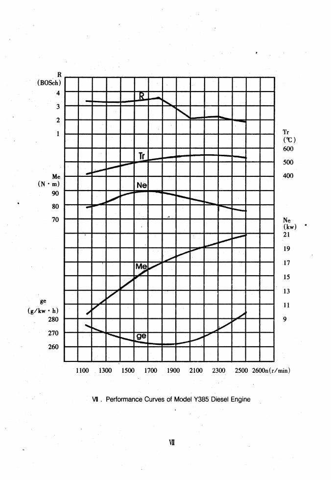
VI . Performance Curves of Model Y385 Diesel Engine
vn

-I
-
SECTION 1. DIESEL ENGINE SPECIFICATIONS AND
TECHNICAL DATA
I. Specifications of Diesel En2ines (see Table I)
Table 1
Model Y385 Y385T Y485 YD 1485
Type Vertical , water-cooling, four-stroke, vortex Vertical , water-cooling, four stroke, direct injection chamber
Number of
ratio
Total displacement(L) 1.532 Firing order 1-3-2
Rated 19.2-24 Rated 2400-3000
?:84 Min.specific fuel consumption �267.9
at full load(glkW.h)
Specific lube oil consumption(glkw.h)
Advancean�e ofsupplyfuel/s IO±IIJOOO peed(before TDCX' )/r/min I (with Advance Device) 12800 /2600 /2400
Injection Pressure
Direction of crankshaft rotation (facing to flywheel )
Cooling method
method
Net 165 j Overall dimensions 587X494X610
22
2200
?:82.9 �278.8
(with fan)
14±1
190
4 85
90 95
18 2 .043 2.156
1-3-4-2
26-32 27-33 29.4-36 24Q0-300 2600-3200 260Q-3200
?: 112 ?: 108.3 ?: 118.2 �267.9 �248.9 �247
2.72
IO±Inoo (with Advm !kvice) 12800 /2� /2400 (with Advance Device) /2600
12± 1/�280 (with Advance Device )
112±0.5 19.6
Counterclockwise
Forced water Cooling
Electric 195
687X494X610 687 X 494 X 623
18±1 12600

ll .Specif"aeation of Main Accesries( see Table 2)
Table:
N2 Designation Specification
Y385 Y385T Y485 YD.485 YND485Q
Type I pump I ,BQ or IW pump BQ pump Fuel Governor . All·speed , mechanical centrifugal I injection
pump Plunger diameter(mm) 7 7,7. 5,7 7.5
Fuel delivery pump Single-acting piston type Model P21 PF68509
, Pinde4ypy.zs,4SJ .. ZCKI54S423 ZCKI54S425 Fuel Diameter of Nozle
2 l 4 -ll0.23 4-ll0.25
injector hole(mm)
Injection p�) . :..:;:�llJ-±0.5 19.6+o1
Type Gear
3 Lube pump Speed(r/min) 1300 1800 2748
Capacity(L/min) 18 30 22.4 Pressure(Kpa) 0.4
Type Centrifugal, volute, single-suction
4 Water Speed(r/min) 3000 4000
pump Capacity(L/min) 80 160
Lift(m) 5 8 Type Series DC motor
QDJ322C;QDI315A,DI38Y 5
Starting Model QDI315A, Dl38Y
motor Voltage(V) 12
Power(kW) 1.8 or 2.5 25
Type Silicon rectifying shunt dynamo
6 Dynamo Model JFII Power(W) 350
Voltage(V)
Fuel filter Type Single stage, paper element
Model C0506A
Lube oil Type. Single stage, paper element .8 filter Model J0708 J0810H
9 Air filter Type Single stage, paper element
Model Kl317A
10 Electro1hermic Type Shrouded NO accessory plug ·
Model 10-12-65
1-2

ID.Main technical Data of Diesel En2ine
1. Valve lash(mm)
Intake valve( cold)
Exhaust valve( cold)
2. sinkage ofvalve(mm)
0.20,. 0.2S
0 .. 2s--. 0.30
0.7 .. 0.9
3.Torque limits of main bolts and nuts(N • m)
Cylinder head bolts
Main bearing cap bolts
Connecting rod bolts
Flywheel bolts
ISO,. l70(Y38S,Y38ST,Y48S)
17S--. 19S (YD148S,YND48SQ)
110--. 130 ;140-160(YND48SQ)
so--. 60;70-80(YND48SQ)
4.Temperature and pressure limits 60'"'-70
(l )Exhaust temperature("C )
n? 3200rpm t� 620
3200rpm>n> 2600rpm t� 600
n� 2600rpm t� sso
(2)Lube oil temperatureCC) � 100
(3)Lube oil pressure(Mpa)
At normal operation 0.2 .. 0.4
At min. Steady Speed ? o.os
S.Govemor Characteristics
Min. idling steady Speed � 900rpm
Steady regulation S% .. 10%
1-3

N .Fit Clearance and Wear Limit of Main Parts(see 3)
Table 3
N2 Designation
1 Connecting rod journal and connecting rod bushing
Assenbly limit Wear limit
(mm) (mm)
o:2o
2 Piston pin and connecting rod small end bushing
3 Piston skirt and cylinder
4 clearance between the 1st ring and its groove
5 Side between the 2nd ring its groove
o.o25-o.o44 0.10
0.100-0.155 0.40
0.20 0.060-0.092
I o.o4o-o.on I 0.18
6 Side clearance between the oil scraper ring and its groove 0.030-0.067 0.18
7 Gap of the 1st ring 0.300-0.450 1.60
8 Gap of the 2nd and oil scraper ring 0.25-0.450 2.20
9 Crankshaft main journal and main bearing o.o7o-o.l39 0.25
10 Camshaft and bushing - 0.050-0.100 0.18
11 Idle gear shaft journal and bushing I 0.025-0.075 0.18
Intake valve stem and valve guide 0.15
0.040-0.077 0.15 13 Exhaust valve stem and valve guide
14 Rocker arm shaft and bushing 0.020-0.074 0.20
Axial clearance of crankshaft 0.075-0.265
0.050-0.220
16 Axial clearance of camshaft
1-4

SECTION2. OPERATION
I . Fuel Oil ,Lube Oil and Cooling Water
!.Fuel oil
Users can select the proper,grade of fuel oil accrding to the local ambient temperature. In
the general area in China, the grade of fuel oil is according to the standard GB252 light diesel
fuel. Use grade "0" light diesel fuel in summer, while in winter, use grade " 10" light diesel
fuei.Before being filled into the engine fuel tank,the diesel fuel must be settled for a long period
(normally at least 48 h).lben draw out the upper part.The fuel should be filterd by silk cloth
while filling it into the engine fuel tank.Jt will extend service life of iQjectors and iQjection
pumps by Using the well settle diesel fuel.
2.Lube oil
In the general area in China,users can select the proper grade 'according to GB/T11122 '
Lube Oil of Diesel Engine. Use grade CD40 lube oil in summer,while in winter use grade CD30
lube oi I. When being filled into the engine oil tank, the oil should be fitered by screen.
3.Cooling water
It is recommended to use soft water such as rain water,city tap water,or clean river water for
engine cooling.Well water or tap water from well water could not be used. Cooling water
containing too much minerals will form water scall in an engine cooling system,affecting the
engine cooling efficiency and giving rise to engine troubles.
Hard watet(well or spring water,etc.) should be softened before being used.There are two
softening methods;
(1 )Boiling up the hard water;
(2)Adding 20g caustic soda (sodium hydroxide) to each 30L hard water to make up a
solution.
When the engine operates in cold weather where the cooling water is liable to freeze,anti -
freezer can be added to the cooling water to prevent it from freezing. Glycol or alcohol aqueous
is most ordinary.
If it is difficult to start the engine under lower ambient temperature, heat the water to about
80"C before filling it into the cooling :5ystem ..
2-l

ll . Preparation before Starting
l.Check the tightness an d r�liability of al connecting parts. Check control levers (speed control lever and stopping lever) to see whether they can be moved freely.
2.Rotate the crankshaft several turns,be sure that all moving parts move freely.
3.Check the oil level in the oil sump and pump to see whether it is kept within two
marks on the dipsticks.Make sure that the fuel tank has sufficient fuel and that the fuel 'pipelines
are unblocked.
4.0pen the fuel tank cock.Check whether there is air in the fuel systcm.If necessary,loosen
the vent screws on the fuel filter and injection pump,operate the priming pump on the fuel
, delivery pump by hand until the fuel flows out of these screws without bubbles,and retighten the
vent screws.Mter that,loosen the union nuts of injection pipes on the injectors and rotate the
crankshaft to bleed air from injection pipes,then retighten the union nuts.Check all fittings of the
fuel system to see whether there is any leakage at all joints.
5.Check the radiator to see whether it is filled fully with water and whether there is any
leakage at all ioints.
6.Check the accessories to see whether they are firmly and reliably connect-ed.Check the
electrical system to see whether the battery is fully charged,all . wirings are correct and all
connections are tightened. f
?.Check the clutch to see whether it has disengaged.
m. starting
l.Set the speed control lever at the middle speed position.
2.Turn the ignition switch to "preheating" position to heat the electrothermic plug for 20-
30s.
3;Turn the ignition switch _to "on"position.Press the starting button to start the engine.If it
fails to start,release the button immediately.Wait 2minutes 3 minutes,befor� starting the engine
again.If the engine fails to start after 3 attempts,check the cause and remedy the fault.
4.As soon as the engine has been started,release the press button immediate-ly.Then turn the
ignition switch to another position to charge the battery.At the same time move the fuel control
lever until the engine runs at idling speed.Check the op-eration condition of the engine to see
whether is any abnormal noise.Especiallypay close attention to the readings of oil pressure
gauge,which should be within specified pressure limits.Then warm the engine up with engine
speed gradually in-creasing to 1800-2000r/min.
2-2

- IV. Operating
l.Do not load the engine until the cooling water temperature is over SOOC and the lube oil
temperature is over 400C. The engine should not be operated undrer rated operated under rated
output before the outlet water temperature reaches approximately 800C.
2.1ncrease or decrase the engine load and speed gradually and evenly.In normal case,do not
load and unload the engine suddenly.
3.During operation,observe the gauges on the instument panel frequently where the readings
should be within the specified ·limits.Pay close attention to the exhaust gas color and the
operating noise.lf there is any fault,stop the engine and inspect it.
V. Stopping
l.Before stopping,take off the load and reduce the engi11e speed gradually.Let it run at idling
speed for a few minutes.Do not stop engine until the outlet water temper-ature falls to below
700C.
2.Mter stopping the engine, the ignition switch should be turned to the middle position.
3.1n winter,when ambient temperature falls to bellow SOC ,after the engine stops and the
cooling water temperature falls to below 600C ;open al drain cocks on the cylinder block and
radiator to drain off all water remnant within the cooling system,in order to avoid damages of
parts due to freezing.lf anti - freezer is added to the cooling water,it is not necessary to drain
off.
2-3

SECTION 3. MAINTENANCE
For rel iable engine operation. with less wear and longer service life,all mainte-nance work
must be carried out as follows.
I . Routine Maintenance
1. Check the oil level in the oil sump and it should be between two marks on the dipstick
and near the upper one.For a new engine or the engine reused after stopping for a long period,the
lube oil must be filled to the upper mark,and operate the engine at lower speed for 5-lOmin,then
stop the engine and measure the lube oil level once again.
2. Check the cooling water level in the radiator.
3.Check the lube oil level in the governor of the injection pump,replenish the oil to the
specified level if needed.
4.Eliminate oil,water and gas leakags of the engine.
5.Check tightness and correctness of all components attached to the engine.
6.Check tightness and reliability of engine foundation bolts and the connection between the
engine and the dirven machinery.
7.Keep the engine c�ean.Oil,wate;r and dust gathered on the engine surface should be wiped
away with a dry rag or cloth dipped in gasoline .. Especially keep the electric equipment clean and
dry and clean out the dust on the fins of the radiator.
8.For the new engine,after 50h trial running,renew the lube oil in the oil sump,fuel injection
pump and governor,and flush the oil filter element,oil sump and oil strainer.
9.Promptly eliminate the troubles and faults found.
ll .Maintenance after Every lOOAccumulated Operating Hours
Besides the "routine work,and the following items:
l.Renew the oil in the sump.
2.Clean the oil filter or renew the paper element if necessary.
3.Clean the fuel filter or renew the paper element if necessary.(It may as be replaced
after every 200 accumulated operating hours.)
4.Clean the oil filter or renew the paper element if necessary.
5.Clean the valve lashes, readjust them according to the recommended procedure if
necessary.
3-1

6.Check the tension of the fan belt,and readjust it if necessary.
7 .Fill the nipple of cooling water pump bearing with ZG -4 calciumbased grease with a
grease gun.
8.Clean out the dust in intake manifold,clean the inside of the aircleaner,brush off the dust
gathered on the paper element surface,and clean the inside of the exhaust manifold and silencer.
9.After every 200 accumulated operating hours,check .the injection pressure and spray
·pattern of injection.!£ necessary,dismantle the injector,clean the nozzle set,and readjust the
injection pressure .
. 10.Check the voltage of battery and the specific gravity of battery acid,which should be
within 1.27-1.28(at ambient temperature of 20't:).When it is less than 1.14,the should be
recharged.The level of battery acid should be 10-15mm above the pole plate.H insufficient,add
distilled water to the required level.
11.All parts dismantled for maintenance should be washed,and cleaned and correctly
reassembled.After reassembly,start � engine and eheck whether it is in proper operation,All
faults should be remedied.
ID.Maintenance after Every 500 Accumulated Operating
Besides the work of maintenance after every 100 �ccumulated operating hours,the following
items are needed:
l.Check the injecion pressure and spray pattern of the injector.lf necessary,dismantle the
injector,clean the nozzle set and readjust the injection pressure.
2.Check fuel delivery of the injection pump,and recalibrate it ·on a test bench if possible.
Ch�ck the injection timing,and readjust it if necessary. 1
3.Check the sealing of the intake and exhaust valves.H necesary,grind and lap the valve
seats and readjust the valve lashes.
4.Check the tightness of the connecting a rod mian bearing cap and flywheel bolts.
5.Retighten the cylinder head bolts and adjust the valve lashes according to the rule given
in section 4.
6.Clean or replace the paper element of air cleaner.
?.Clean the cooling system.The cleaning solution can be prepared by adding 150 grams of
caustic soda (NaOH) to every litre of water.Before cleaning,drain the system completely and then
fill in the same capacity with cleaning solution.Let it remain in the system for 8-12h.Then start
the engine and run it until the temperure of cleaning solution reaches normal operating
temperature.Stop the engine and drain the system immediately in order to avoid settling of scale
within the system.Finally,flush the system with clean water until all sediment is flushed out.
3-2

8.Check whe ther the thermostat is in good order.Examine the water dropping out from a '
weep hole of the water pump.lt is necessary to renew the water seal,if flowing out too much of
water.
9.Check the wiring contacts of the electric equipment to see whether they are connected
firmly and well.Bumt marks should be removed.
10.After every 1 ,00 accumulated operating hours,add the following items;
(1 )Make an overall check .on all parts and necessaiy adjust-ments and
repairs.
(2)Dismantle the dynamo and starting motor.Clean out the dirty grease in the bearings and
refull them with clean grease.Check the pinion of starting motor.
11.After every 1 , 500 accunulated operating hours,add the following items:
( 1 ) Remove the cylinder head,check the valve and valve seats and other parts of cylinder
head assembly.
(2)Remove the carbon deposits on the surfaces of cylinder head,liner, piston and piston
ring,etc,and wash down them.
( 3) Check and measure wear of the pistons and piston rings.
( 4 )Check and measure wear of the cylinder liner.
(5)Check and me�ure wear of the crankshaft main jou�als.and crank pins. Clean lube oil
passages of the crankshaft.
(6)Check wear of the main bearing and connecting-rod bearing shells.
(?)Clean oil passages of the cylinder block and replace lube oil.
IV .Preservation and Storage of Engine
H the engine is to be put out of service for a comparatively long period of time,it 1s
necessary to prese�e it according to the following procedure:
l.Mter the engine stops and still does not cool yet,drain out completely the lube oil,cold
water and fuel immediately.Clean the oil sump and oil strainer.
2.Clear out the dust and oil on the engine surface.With antirust oil smear all the unpainted
exposed surfaces of engine except rubber and plastic parts.
3.Heat the filtered lube oil to 110-120't,until all bubbles in the surface of oil disappear.
Then pour the dehydrated oil into the oil sump until oil level reaches the upper mark,and turn
the engine, in o�er to make sure that the lube system is completely filled up with this oil.
3-3

4.Pour some dehydrated oil into cylinder through injector-assembled h?les on the cylinder
head,and turn the crankshaft to make sure that the piston,piston ring,cylinder liner and valve seat
are all covered with a layer of this oil.
5.Block the outlets of intake and exhaust manifolds (silencer)with wooden plugs or wrap up
properly with plastic film in order to prevent any dust from getting in. ·
6.The engine should be stored in a clean room with good ventilation and low humidity,The
engine should be covered.Chemicals near it are strictly prohibited.
The preservation according to the above procedure may be valid for 3months.Over this
period;repeat the procedure.
3-4

·-.
SECTION 4.ENGINE ADJUSTMENT
· I . Adjustment of Valve Lash
When the engine is maintained and repaired,it is necessary to check and adjust the valve
lashes. The recommended method of adjusting the valve
system and valve lash is as follows:
1.Remove the cylinder head cover.Check and
tighten the nuts fastening the rocker arm shaft stands.
2.Turn the crankshaft to make sure that the piston
of lst cylinder is at the compression T.D.C. position.
The timing mark on the inspection window of the fly
wheel housing exactly points to the "o" mark on the
crankshaft pulley is aligned with the pointer on the
cover of timing gear housing.
3. slip a feeler gauge between the rocker arm and
the tip the intake or ex-haust valve stems of the lst
cylinder respectively to check and adjust the valve
lashes.lntake valve lash and exhaust valve lash in cold
must be the value specified in section 1. Then after Fig.l Adjustment of valve lashes
turning the crankshaft by 180° to adjust the valve lash of other cylinders according to the engine
firing order(l-3-4-2)for the four cylinder engine and 1-3-2 for three cylinder engine.
ll .Adjustment of Advance angle of supply fuel
To obtain the most economical specific fuel consumption and to ensure normal operation of
the engine,injction timing should be adjusted properly.For the Model 485 diesel engines,the
angle at which injection begins should be the value specified in section 1.
The adjusting method of advance angle of supply fuel is as follows:
1. Vent the air trapped in the fuel system,and turn the crankshaft to fill up the injection
pump wtih fuel.Disconnect the injection pipe of the lst cylinder,turn the crankshaft slowly in the
direction of its rotation and at the same time observe the fuel level in the hole of fuel pipe
union.When this fuel level just starts to rise,stop turn the crankshaft immediately.
2.Check the, timing mark on the inspection window of flywheel housing to see whether it
4-1

aligns with the correct graduated mark of specified advanced injection angle on the flywheel rim
(or on the crankshaft pulley).
3.In case that they do not match with each other,the advanced injection angle can be
adjusted by removing off the front cover on the timing gear housing and loos-ening the three
screws fastening the injection pump timing gear support (see fig.2).1f the injection tim-ing is too
advance,turn the timing gear support an -ticlockwise to the proper angle.Otherwise,turn the
support clockwise.H adjusting range is not enough
due to limitation of the three elongated holes,loosen
a little the three fastening nuts on the triangular
flange of the injection pump and turn the injection
pump.Facing the front end of engines,when the in
jection pump rotates clockwise,the fuel injection
will retard;while the rotates anticlockwise,the
fuel injection will advance.
4.Additionally ,if the engine has injection angle ·
advance device,the advanced injection angle can be
adjusted by loosening the three nuts on the
triangular flange of injection pump and turn the
injection pump shaft.Facing the front end of
engines,when the injection pump rotates clockwise,
Fig.2 Adjustment of specified
advanced injection angle
the fuel injection will retard;while the pump rotates anticlockwise,the fuel injection will advance.
After turn the injection pump once,it is must to tighten the three nuts and check the advance
injection angle aganin untill the advance injection angle fits the spcified value.
m. Adjustment of Injector
Injector test and adjustment must be performed on a injector test in order to adjust injecting
pressure,inspect spray pattern and remedy faults . .
Too high or too lower injector injecting pressure,and abnormal spray, on damaged injector
parts will cause engine troubles,such as black smok1ng,power and speed dropping,increasing ex
haust temperature and diesel knocking.etc.Generally,the "shut off" meth od is recommended to
check a fauly inijector,i.e.loosen the nuts of injection pipe from the injector of every cylinder
4-2

successively,and observe the exhaust smoke. When the cylinder with the faulty injector stops
firing,black smoke would disappear and engine speed is not appreciably affected or not affected
at all.It may also be checked by listening to the chattering action of the injector of every cylinder
with the flywheel rotating.lf the distinct clear sharp sound of certain cylinder could not be heard,
the injector in this cylinder may be faulty.
!.Procedure of injector testing and adjustment
( 1 ) Work the injector tester hand pump until the gauge pressure reaches about specified
injection pressure. Then operate the hand pump slowly and adjust the injection pressure at which
unjection begins. The nozzle should not show any signs of leakage. If fuel drips around the nozzle
tip after several tests, the nozzle set must be dismantled for cleaning and grinding. Then test it
agam.
(2)Remove the lock nut,turn the adjusting screw to get the pressure at the be-ginning of
injection which should be specified value in section l.Then tighten the lock nut,and test it again.
(3)Work the hand pump at a rate of approximately 1 stroke per second and ob-serve the
nozzle spray.The fuel spray should be evtm,and well 'atomized in a shape of cone.At any cross
section of the cone,the atomized fuel should be finely and evenly distributed.Fuel droplets and
irregular pattern which can be seen by naked eyes should not be present in the spray.There r
should be a distinct clear sharp sound at the end of injection.Generally,irregular pattern of the
spray is caused by needle valve seizure, fuel dripping is generated by damaged conical sealing v
surface of needle valve and spray split results from carbon deposits on the tip of nozzle and its
heat deformation.
2.Injector dismantlement and repair
( 1 )Before dismantling the injector.clean off the dirt gathered on it .Clamp the nozzle body
in a pliers lined by copper sheets, on its jaw with the nozzle upward.Turn off the nozzle cap nut
and take out the nozzle set.Draw out the needle valve from the nozzle body and soak it in clean
fuel oil.Then clamp the injector in the vice upside down again.Dismantle the adjusting nut,and
adjusting screw,then take out the injector spring and spindle.
(2) If the nozzle set is seized or emits fuel badly, it must be cleaned.Soak the seized nozzle
in fuel oil for a while,and clamp the needle valve by a pliers with cloth lined.Then rotate and
draw it out slowly ,just to avoid scratching its surface. Decarbonize the needle valve and nozzle
body with woodern chip soaked in fuel oil.It is forbidden to clean them with metal chip.lf the
guiding surface of' the needle valve and nozzle body is not smooth enough,it may be lapped with
4-3

a little bit of clean fuel oil,then clean off any metal particulates in clean fuel. While lapping of
needle valve with nozzle body,never knock the needle valve against the body.
IV. Adjustment of Lube Oil Pres-sure See fig.3 Loossen the lock nut and tum the adjusting screw with a wrench to take the lube
oil pressure within 200 -400kPa (in cold state the pressure q:�ay be higher slightly). After
adjustment.the pressure adjusting screw must be locked by the lock nut.
V. A�justment of Injection Pump The injection pump has tested and cal -
ibrated at the factory .If it is necessary to
readjust,the readjustment must be per-formed in
a injection pump test bench with a standard
injector and injection pipes of standard length
according to the instructions in operation Manual ·
of the Injection Pump.
Fig.3 Adjustment of lube oil pressure
VI .Adjustment of Decompress ion Arm Lash
Tum the crankshaft to make that the piston of lst cylinder is at the compression T.D.C.
position.Tum the decompression arm to decompression position.Loosen the lock nut.Tum the
adjusting screw to bring just into contact with the lock arm of intake valve (i.e.no valve lash).
Screw the adjusting screw by 3/5-4/5 turns again (make the intake valve lifting to 0.6-0.Smm).
Then tighten the lock nut.After this,ac-cording to Item 3 of "Adjustment of Valve Lash" ,make
the piston of another cylinders at the compression T.D.C. position one by one and adjust by the
same method.
4-4

SECTION 5. CONSTRUCTION OF DIESEL ENGINE
I . Cylinder Head
When assembling,cylinder head is fixed on the cylinder block with cylinder head bolts. A
torsion spanner should be used during tightening the bolts.The bolts are tightened several times
in sequence shown in Fig.4 until they reach the specified torque limit.After dismantling and
assembleing the cylinder head it
IS necessary to shut down the
engine,when first warming up
period is over,Retighten each
bolt on the cylinder head
according to the specified value
of torque limit and readjust the
valve lashes.
The intake and exhaust
6 2 3 10
•
Fig.4 Tightening sequence of cylinder head bolts · valves are made of different materials.Each couple of the valve and valve seat should be ground
in order to prevent leakage.
It is necessary to grind when gas leaks out due to burning out,mechanical pitting and wear
appeared on the sealing face of valve and valve seat.When lapping,apply a grinding paste(fine
valve sand)on the conic sealing surface of valve.Then the valve and valve seat are lapped in pair
unitl a even,continuous and lustreless sealing band appears.lt is strictly that the
grinding paste enters the valve guide.Mter lapping,clean the valve,valve seat and valve guide
carefully.Wearing of the valve guide may cause the eccentric wear of valve sealing band which
results in abnormal sealing.Pour some kerosene or diesel fuel into the gas passage,and observe
whether there is any leakage,then check the valve sealing.
The sealing band of valve and valve seat is normally 1.2 -1.6 mm in width.After a long
period of service and regrinding many times, the width of valve sealing band may get wider,
which may cause abnormal sealing.Being kept conce·ntrical with respect to the valve guide hole,
the contact band on valve seat is to be refaced by a reamer. Then gring the valve and valve seat
m pair.
5-1

After service for a long
period and regrinding many
times, the sinkage will
Increase. VVhen it exceeds
2.0mm,replacing the valve seat
should be considered.
Check the valve lashes
frequently. The recommended
adjusting method is shown on
paragraph I of Section 4.1f the
lashes are too large,it may
Fig.S Valve sinkage
affect the correctness of valve timing and the noise level of valve device rises.On the contrary,it
may cause leakage or valve burning out.
ll . Cylinder BLock
The cylinder block is made of cast iron and is of crankshaft centerline off -split face
structure.Besides the fitting bores for the liner and the cylinder head boltholes,on the top plane
of the block there are holes leading water to the cylinder head.Near the rear end of the block
there .are channels delivering
lube oil upward to the cylinder
head.
The water pump . 1s
mounted on the upper front
face· of cylinder block ,a,nd the
gear system is on the lower
part.The flywheel housing 1s
in -stalled at the rear face of
Fig.6 Protruding height of the liner flange plane
relative to the plane of cylinder block
the block.On the block bottom,there are a lube oil inlet,a hole for the lube oil pump and tap
holes for installing the sump.
There are a side cover and a breather on the left side of the block (facing to the front end).
There are the lube oil filter,fuel filter and drain cock on the right side of this block. The main
lube oil line and its branches are arranged in horizon.The lube oil passages delivering lube oil
5-2

to the camshaft bushes are slant. When dismantling and repairing the diesel engine,flush all lube
oil passages,and be sure that they are clean and u blocked.All passage plugs should be sealed
reliably and leakproof.
The main bearings are of complete suspension -support type.Since the main bearing caps
and .cylinder block are matched to bore,the matching marks are both on the bolck and mam
bearing caps.Misplacement or inverted installation,when assem -bling,are prohibited. The mam
bearing shells are made of high-tin aluminium-base alloy.When dismantling for cleaning,be sure
that the upper and lower bearing shells are in right places(the upper shell with an oil groove).The
crankshaft thrust plates are assembled on the last main bearing with an upper piece and a lower
piece on each side.The thrust plates bear the axial force from the crankshaft.There are oil
channels on its operating surface which should be located against the thrust planes on the crank,
and its back surface is smooth.Never locate them in reverse.When tightening the main bearing
blots,two bolts on the bearing cap should be tightened several times in turn.Before tightening the
main bearing cap,strike the crankshaft forward and backward in order to keep the upper and
lower thrust plates in the same plane.Then tighten the bolts until they reach the specified
tightening torque.When completing the crankshaft assembly,turn it at the flywheel end by hand to
check whether it can be moved freely.
The liner is slipped into' the cylinder bore vertically so that deformation of the liner may be avoided ' '
The liner flange plane should protrude out the top plane of cylinder block by 0.07 ...15mm to keep an
excellant sealing between the cylinder liner and cylinder head,as shown in Fig6.
m. Piston and Connecting-rod
The piston and connecting -r<!d assembly comprises the piston,piston rings,piston pin,
retaining rings,connecting -rod,connecting rod mip,connecting -rod bolts and connecting -rod
bearing shells and bush,etc. The mass difference of piston and connecting-rod assemblies in the
. same engine should be within 20g.
All of the compression rings are made of alloy cast iron.The outer circle surface of the first
ring is plated with porous chrome in order to decrease the wear between the cylinder liner and
piston ring.The second ring has a conical surface.When assem-bling,the surface marked with a
sign"up"should be kept against the top of piston and be careful to avoid assembling in reverse.
The oil-control ring is of tensioning ring type.The radial force of oil ring is still kept while
decreasing the elasticity due to wear.Thus the service life of oil ring is prolonged.
5-3

Check the ring end gap before
assembling the piston ring.The method
measuring this gap is recommended as
follows:Press down the piston nng
evenly into the cylinder liner by 15 -
20mm from the top surface of liner.
Measure the clearance with a feeler
gauge.ln normal case,the measur -ing
value should be 0.2 (Fig. 7).In
case the gap value is less, enlarge it by
a file.lf it is excess,replace it with
another one.In addition,measurement
should be made with a feeler (gauge)to
check the side clearance between the
piston ring and ring groove. The side
clearance for the first ring should be
0.07 -0.1 02mm and 0.05 -0.082mm for
the second ring as shown in Fig.8.
When dismantling and assembling
the piston ring,a spc:cial tool may be
used.The ring end gap of piston rings
should be set off with each other by
Fig. 7 Measurement of piston ring end gap !.Thicknes feeler(gauge) 2.Piston
ring 3.Cylinder liner
Fig.8 Measurement of side surface
gap of piston ring
120°, to prevent being in line with the piston pin seat hole.
If the piston ring is seized arid could not move when checking,soak it in diesel fuel(kerosine
or gasoline)for 24h or more.Then knock the piston ring slightly to make it become flexible of
itself.On getting out the piston ring,clean it in diesel fuel or carbon tetrachloride.
Check the piston to see whether there is any cracks or scars,Change the defective piston and
renew its rings.
The cross section of the connecting-rod is 1-shaped,with the splitting surface of large end
being perpendicular to the center line of connecting -rod.Boring the connecting -rod hole and
connecting-rod cap must be mated.Therefore when as:-sembling,pay close attention to the mating
marks on both the connecting-rod and connecting-rod cap in order to avoid making mistakes.
5-4

connecting-rod bearing shell is made of steel with high tin-aluminium alloy.When the clearance
be -tween the connecting -rod shells and crankshaft journal exceeds the specified value after
wearing or severe stripping and burning occur on their surfaces,they must be renewed in pair.
During engine overhaul or renewing the connecting-rod,check the axis paral-lelism of the
connecting-rod small end to the large end,which is specified to be within O.Olmm/lOOmm(both
in vertical and horizontal direction).lf it goes beyond the scope,alignment should be made.
Before dismantling the piston and connecting-rod assembly in cylinder liner or assembling,it
is necessary to scrape and clean the carbon deposit and greasy dirt on the top part of cylinder
liner.Before assembling,smear some clean oil on the cylinder liner bore,extemal surface of piston
and piston rings,connecting-rod bearing shells and crankshaft joumal.Then place the piston guide
sleeve in the cylinder liner,fit the piston and connecting -rod assembly into the cylinder liner
carefully,and tighten in tum the connecti-ng-rod bolts according to the specified tightening torque
limit in several separate times.After finishing the assembly,tum the crankshaft,be sure that it
rotates smoothly.
IV. Crankshaft and Flyw�el
The crankshaft timing gear and pulley are fitted on the front output end of crankshaft.
Positioned by the locating, pin, the flywheel is fitted on the rear end flange of the crankshaft with
six bolts tightened according to the specified torque val-ue. A bearing E60203,which supports
the transmission shaft of gear box,is fitted on the flange center at the rear end of the crankshaft.
An angular calibrating line is marked on the crankshaft pulley and a pointer,which is fitted on
the cover of the timing gear housing,indicates the reading of advanced injection angle.
A flywheel gear ring is bound on the outside diameter of flywheel in shrinking fit.A
calibrating line,which provides observation for advance d injection angle,is marked on the
flywheel.
V. Camshaft
There .is a gear driving the lube oil pump in the front of th� last set of cams (facing to the
front end).When the camshaft revolves,the cam on the shaft drives the tappets,push rods,valve
rocker arms and valves,which respectively control the intake and exhaust valves for each
cylinder.
5-5

There is a thrust flange at the front end of camshaft,and a thrust plate of camshaft is located
at the front end to control the camshaft axial moving.The lube oil is deliv-ered to the camshaft
bushings separately through the main oil line.Before assembling the front bushing of camshaft,
check whether the oil holes on the bushing and oil passage in the cylinder block communicate
with each other. As the camshaft gear is engaged with the driven gear on the oil pump,therefore,
before dismantling the camshaft,it is necessary to disassemble the lube oil pump,then draw the
camshaft out from the front end.
The axis of the tappet deviates from the center line of cam width.During oper -ating,the
tappet rotates so as to provide an even wearing on the bottom surface and the cylindrical surface of tappet.
Vl: Gear Transmission System
The gear transmissio n system consists of the crankshaft timing gear,timing idler,camshaft
timing gear,injection pump timing gear and hydraulic pump gear.
Except the hydraulic pump gear,all the timing gears are al mark�d with timing signs which,
when assembling,should align wtih each other at the meshing position (the single tooth marked
with a sign is inlaid between the two adjacent marked teeth)in order to ensure the movement
relationship of al moving parts,as shown in Fig.9.
Fig.9 Timing gear meshing signs
5-6

Special tools are nec-essary for dismantling or as-sembling the crankshaft tim-ing gear.The
camshaft timing gear can be got out by two bolts M8 on the gear spoke which are turned
staggeringly and evenly.The timing idler is located on the cylinder block by slide fit.The
injection pump timing gear is assembled on. the timing gear seat which is fixed on the camshaft
of the injection pump.Whenever three bolts setting the injection pump gear are loosened,the
injection pump gear can be drawn out.The injection pump gear is pushed out when the three
bolts M8x35 are stag-geringly tightened on the gear seat.
VlFuel and Governing Sy�m
The fuel and governing system is the main operating section of the diesel �ngine . It IS
composed of the fuel
delivery pump, fuel filter,
injection pump, governor,
fuel injection and fuel
return pipes, etc.as shown
in Fig.lO.
The fuel is pumped
by the fuel delivery pumH
from the fuel tank into
the injection pump
through the fuel filter. The
diesel fuel is delivered
through the injection pipe
under high pressure
produced in the pump,
and is then atomized by
the injector before
burning m the
combustion chamber .
2
3
Fig.lO Fuel and governing system
l.Fuel return pipe 2.Fuel injection pipe 3.Injector
4.Injection pump S.Fuel mter 6. Governor 7 .Fuel delivery pump
4
5
The fuel delivery pump is a single-acting piston type pump located ori the outside of the
injection pump. The eccentric cam;which is set on the camshaft of in-jection pump,drives the
fuel delivery pump,which finally presses the fuel into the fuel cavity in the injection pump.
5-7

The injection pump has been calibrated by the manufacturer.Be sure not to dismantle it at
will. When the dismantlement,repairment and adjustment are required,it is forbidden to
interchange the pluger sets and discharging valve sets,and be sure to keep clean when
assembling.
The all speed mechanical-centrifugal governor is applied.The governing handle can be
oper-ated to control the speed of diesel engine.When the governing handle is turned in the
direction of tightening the governing spring,the fuel supply would increase and the engine speed
would be up consequently.When this fuel supply would decrease and the relevant engine speed
would go down.Do not move either the high speed or the idling speed set screws or screw the
maximal fuel supply set screw on the governor at will during operating.
On the governor housing,a stop handle is mounted which,if necessary,can be operated to
stop the engine at emergency.
The needle valve and its body are a precise set lapped in couple, therefore, close attention
is paid to that,when dismantling and assembling them.Be sure not to' inter-change them and to
keep them clean.
VI J .. ubricating System
The lubricating system is composed of the strainer,lube oil pump,oil filter and pipelines,as
shown in Fig.ll.
The engine adopts pres-sure and splash lubrica-tion.The pressure lubrication is applied to
the main bearing,connecting-rod bearing,camshaft bushing.The cylinder sleeve,piston,piston pin,
connecting -rod bushing,cam and its tappet,as well as valve and its guide are lubricated by
splashed oil spray.The bearings for the water pump shaft are lubicated regularly by adding
lubricating grease.
The lube oil is sucked up to the lube oil pump from the oil sump through the strainer and
the oil inlet pipe,and pumped into main oil line through the oil filter.One path of the lube oil
lubricates the main bearing and the connecting -rod bearing through the oil hole on the
crankshaft;other path pf the oil lubricates the camshaft bushing,and also the oil is supplied
intermittently to �he rocker arm shaft bushing throrgh the eccentric oil channel in the rear
journal of the camshaft;and the third path of the oil is fed .to the timing idler bearing. The lube oil
pump is of slantingly mounted type.A single.
stage paper ciutridge oil pump is used. The filter
element can be replaced regularly.In case of blocking up during operation,the oil flows into the
5-8

main oil line by opening the safety valve while the oil filter loses the function of filtration,so it iS
necessary for the cartridge to be cleaned or replaced regularly according to the maintenance.
7�
Fig.ll -Lubricating system l.OU sump 2.Strainer 3.Lube oil pump 4.Piston and connecting-rod IIS!lembly and cylinder liner
S.Lube oil filter 6.Gear train 7,0n presre gauge S.Rocker arm 9.Valve push rod,valve tapj>et and block hole for tappet 10.Rocker an shaft 11.Valve and valve guide 12.Camshaft and
bushing 13.0illines in the bloc:k 14.Crankshaft and bearing
5-9

·IX. Cooling System
The cooling system is a forced circular
water cooled type,as shown in Fi�12 The
system consists of a radiator,water pump,
cooling fan,thermostat and diversion hood,etc.
The cooling water,pumped from the
radiator into the cylinder block water
gallery,flows tangentially and round to the
cylinder liner,then up to the cylinder head.
The hot water from the front end of cylinder
head flows back into the radiator through
the thermostat and outlet water pipe.When
the temperature of cooling\ water is below
Fig.12 Cooling system
!.Radiator 2. Thermostat 3.Cooling fan
4.Water pump S.Inlet water pipe
70'C,the thermostat closes,and the cooling water will be short-cut for circulation from the bn,mch j
water pipe on the front end of the cylinder head to the water pump inlet pipe and the water
pump;when the temperature of the cooling water is above 70-80'C,the thermostat opens,and the
cooling water flows into the upper part. of the radiator through the thermostat and flows downward
the thermostat and flows downward along the flat-tube into the lower part of the radiator,during
which the cooling water is cooled by the fan and completes the regular circulation. The cooling
fan can be of either suction or blast type according to its application.
The centrifugal water pump is driven by the fan belt on the crankshaft pulley.ln case of
severe water dropping out from the weep hole at the lower part of the pump housing due to the
damage of water seal during operation,it is necessary to replace the water seal but blocking the
weep hole at the time of leakage is not permitted, or the water will enter into the bearings, which
causes their quick wear.Replacement must be .considered while abnormal noise occurs during
operation. The grease cup of water pump must be filled regularly with ZG -4 calcium based
grease which amounts to about 112 -113 of the capacity of bearing cavity according to the
maintenance.The bearing will be overheated with excessive grease.The single valve type
thermostat with corrugated pipe is filled with temperature-sensitive fluid which can
automatically control the valve opening and closing.
The fan belt must be checked and adjusted regularly for its tension according
to the procedurs for the maintenance.The sla�k is 10-20 mm when pressing the belt
between the fan and the dynamo pulleys.
5 10

X. Electric System
The electric system is composed of the battery,starting motor,dynamo,elec
trothermal plug,starting button and instruments,etc.,as shown in Fig.l3.
7 8
Fig.13 Electric system
l.Battery 2.Starting motor 3.Wire 4.Glow plug S.Prebeating and startingwitch
6. Galvanometer 7. Ignition switch 8.Regulator 9.Dynamo
The parallel excited silicon rectifying dynamo model JFll comprises the three -phase
alternator and silicon diode rectifier.Be careful that th� armature must be ne -gitive pole
grounded,or the dynamo will be damaged.
Refer to operation and maintenance manual for JF series silicon rec·tifying dynamo for the
operation and maintenance of the dynamo.
After turning on the starting switch,the flywheel gear ring is engaged with the motor pinion
by the solenoid,meanwhile the flywheel is driven by closing the current circuit of starting motor.
As soon as the engine is started,the starting switch must be turned off immedi-ately.Then the
core along with the pinion returns to the original place under the ac -tuation of spring. The
continuous working time for the starting motor ·should not exceed 15 seconds. The interval
between two starting operations is 2-3 minutes.It is nec-essary to check and eliminate the faults
in case of starting failure for three attempts. The electrifying time of the glow plug each time
during operation, is not permitted to be over 30 seconds.
5-11

SECTION 6. FAULTS AND REMEDIES FOR DIESEL ENGINE
I • Hard or Refuse to Start(see Table 4)
Table 4
Causes Remedies
l.Fuel filters and fuel pipelines blocked. l.Clean.
2.Air trapped in fuel system. 2.Exhaust air and tighten allfuel pipeline connector.
3.Advanced fuel injection angle incorrect. 3.Readjust it according to specifications.
4.Fuel spray abnormal. 4.Readjust fuel injection pressure according to specifica-
tions and clean or replace injector needle valve sets.
5.Compression preessure low. 5.Cheak or replace piston rings, and cylinder liners.
().Valve lash incorret.
7 .Battery charge insufcient.
8.Wire connections loosened.
9.Ambient temperature too low, and oil
too viscous.
H • Power Insufcient (se Table 5)
Table 5
Causes
l.Compression pressure inside cylinders too
low.
2.Adv8l_lced fuel injection angle incorrect.
3.Valve l'lSh incorrect.
4.Fuel supply for each cylinder unbalanced.
5.Air filter clogged.
Grind valves.Cylnder head nuts should be tightened in
case of leakage on cylinder head gaskets.
6.Adjust it according to specifications and align gear
marks.
7.Charge it.
8.Check and tighten wire connections.Clean up contact
points.
9.Preheat cooling water and lube oil.
Remedies
l.Refer to item 5 in paragarph I and replace
components exceeding wear limit.
2.Adjust it according to specifications.
3.Adjust it according to specifications.
4.Adjust fuel injection pumps to proper supply.
5.Clean.
6.Fuel injection pumps, fuel injector sets
worn off or fuel injection pressure incor
rect.
6.Replace them with new sets, adjust fuel injec
tion pressure and check fuel spray.
7.Adjust it with speed governing handle in order
to reach specified speed. ?.Rotation speed
6--1

il. Smoking Exhaust (see Table 6)
Table 6 .
Causes Remedies
l.Engines overloaded. l.Reduce the load properly and in case of unsuited matching.adjustment should be made.
2.Fuel injectors not well atomized. 2.Check the injection pressure and fuel spray.Replace then in case of damage.
3.Fuel unqualified. 4.Combustion incomplete.
3.Use qualified. fuel. 4.Mainly caused by unqualified fuel injectors,incorrect
advanced fuel injection angle,leakage at cylinder head gaskets and low compression pressure.Remedy
· in accordance with specific problems.
IV. Knocking Noise in Engine (see Table 7)
Table 7
Causes
!.Advanced fuel injection angle incorrect. 2.Air trapped in fud systems. 3.Fuel supply for each cylinder unbalanced. 4.Fuel unqualified. 5.Wear of certain components exceeds limits.
Remedies
!.Readjust it according to specification. 2.Exhaust air. 3.Readjust fuel supply. 4.Use qualified supply. 5.Replace them.
V .Lube Oil Insufcient or No Presre (see Table 8)
Table 8
Causes
1. Oil level in oil sumps too low.
2. Serious leakage from oil pipelines.
3. Oil strainers, oil filters and pipeli:Q.es clogged.
4. Oil gauges dama�ed or gauge lines choked. .
5. Oil too thin.
6. Oil pump gears seriously worn off, with excessive
clearance.
Remedies
l.Add oil up to mark line on dip sticks.
2.Eliminate leakage. 3.Clean and replace elements if necessary. 4. Check and replace elements if necessary. 5.Use qualified oil. 6.Adjust the clearance or replace them.
7. Pressure relief valves of oil filter cease to function.
7 .Check and repair or readjust them.
8. Main bearings, connecting -rod bearings and 8.Check and repair or replace them. camshaft bushings seriously worn off with excessive
clearance.
6-2

VI. Overheating of Engine (se Table 9)
Table 9
Causes
1. Temperature of cooling water too high:
( 1) Insufficient cooling water or vapor lock
in water pipes.
( 2) Bad working state of water pumps.
( 3) Water scale in cooling sysytems too thick.
2. Oil temperature too high:
Remedies
( 1 ) Fill the tank to make cooling water level
higher than the center line of water pump.
(2)Check water pump clearance and tightness of
belts. Eliminate leakage.
( 3) Remove it.
( 1) Insufcient or excessive oil. ( l) Cheak whether the oil level is between the
dip stick scale lines.
( 2) Oil pressure too low with insufcient ( 2) Refer to paragraph V.
3. Engines overloaded 3. Relieve load.
VI Engine Runng-away (se Table 10)
Table 10
Causes
1. Malfunction of governors.
2. Control rod of fuel injection pump gets
stuck.
3. Injection pump delivery too much.
4. Excessive oil burnt.
Remedies
1. Stop engines immediately, check and repair.
2. Stop engines immediately, check and repair.
3. Stop the engine and readjust injection pump
delivery.
4. Stop engines immediately, check and repair.
6-3


~ �:l:t(1:
Production permit No.: XK06-002-00129 Product standard: Q/321284 JCA08( 40 )-2002