Embed Size (px)
Citation preview

5-Port Solenoid Valve
Series VQC
CAT.ES11-80 A

Features 1
Series VQC1000/2000/4000
(Based on IEC529)
Connector
Type(Series)
VQC1000
VQC2000
VQC4000
Manifoldpitch (mm)
10.5
16
25
Flow characteristics Note)
Metal sealApplicable
cylindersize (mm)
to ø50
to ø80
to ø140
Compact and high flow
Connector entry direction can be changed with a
single pushThe connector entry direction can be changed from the top to the side by simply pressing the manual release button. It is not necessary to use the manual release button when switching from the side to the top.
Top entry
Side entry
Conforming to IP67 for protection from dust
and moisture
M12/M8connector selection available
For I/O SI unit(DeviceNet compatible)
Input blocks
Serial transmissionEX250
Note) Values for 2-position single from the cylinder port to the exhaust. (From 2 to 3 and from 4 to 5)
Series
EX500
Connector Type Manifold
(For kits S and T)
Outstanding response timesand long life
(Metal seal: Single type with light and surge suppressor)
VQC1100: 10ms ±2ms; 200 million cyclesVQC2100: 20ms ±2ms; 200 million cyclesVQC4100: 17ms ±3ms; 100 million cycles
Accommodates gateway type serial wiring
• Gateway unit types are DeviceNet, PROFIBUS-DP and Remote I/O.
• Because just one gateway unit controls up to 4 branch lines, it offers much more freedom in choosing valve mounting locations than do conventional serial units.
• Manifolds and input blocks can be mounted in close proximity of actuators, thus effectively shortening air piping and electrical wiring lengths.
• Since wiring is “prepackaged” into one multi-connector type cable, wiring work is not only made easier, but much more accurate.
• A single cable from the gateway provides both signal and power to each branch, thus eliminating the need for separate power connections for each manifold valve and input block.
• The use of a multi-connector for input blocks makes manifold station expansion or reduction a breeze.
NEW CONCEPT
Rubber sealC[dm3/(s•bar)]
0.72
2.6
6.9
b
0.25
0.15
0.17
Cv
0.18
0.60
1.7
C[dm3/(s•bar)]
1.0
3.2
7.3
b
0.30
0.30
0.38
Cv
0.25
0.80
2.0

Features 2
Dual 3-port valves, 4 positionsVQC1000/2000 (Rubber seal type only)
A wide variety of prepackaged wiring configurations
R1 A P B R2
VQC1A01VQC2A01
VQC1B01VQC2B01
VQC1C01VQC2C01
N.C.valve
N.C.valve
N.O.valve
N.O.valve
N.C.valve
N.O.valve
Model A side B side JIS symbol
1(P)
5(R1)
3(R2)
4(A)
2(B)
1(P)
5(R1)
3(R2)
4(A)
2(B)
1(P)
5(R1)
3(R2)
4(A)
2(B)
S Kit(Serial transmission) F Kit
(D-sub connector)
Protective enclosureconforms to IP 67
T Kit(Terminal block box)P Kit
(Flat ribbon cable)
• Our four standard wiring packages bring a world of ease to wiring and maintenance work, while the protective enclosures of two of them conform to IP67 standards.
• The S Kit is compatible with a combined I/O unit.(If used with gataway unit, SI must be output only.)
ReplaceableOne-touch fittings
Single mounting screw,clamp construction
NEW CONCEPT
(Refer to the connector wiring diagram)Printed circuit board patterns between connectors are shifted at every station. This allows for viable connections to take place without necessarily specifying whether the manifold station is double, single, or mixed wiring.
Series
EX500
25-pin 26-pin, 20-pin
Connector wiring diagram (mixed wiring)
12345678910
5678910
12345678910
1920
1920
6A
4A
3A
1A
5B
2B
Output
COM
Station 1Double wiring
Station 2Single wiring
Station 3Double wiring
Station 4Single wiring
1234
Protective enclosureconforms to IP 67
Connector type manifold• The use of multi-pin connectors to replace wiring inside manifold
blocks provides flexibility when adding stations or changing manifold configuration.
• Connector clusters give a new dimension to the notion of interchangeability. For example, changing from F Kit (D-sub connector) to S Kit (serial transmission) is achieved by simply changing the kit piece.
• Two 3-port valves built into one body.• The 3-port valves on the A and B sides can operate independently.
• When used as 3-port valves, only half the number of stations is required.
• Can also be used as a 4-position, 5-port type valve.
Exhaust center : VQC1A01VQC2A01
Pressure center: VQC1B01VQC2B01
Serial transmissionEX500
D-sub connector Flat ribbon cable Terminal block box
Wiring
123456789
10
1920
123456789
10
1920
12345678910
1920
123456789
10
1920
12345678910
1920
123456789
10
1920

Features 3
Base-Mounted type: Variations
SeriesVQC1000
SeriesVQC2000
SeriesVQC4000
Met
al s
eal
Ru
bb
er s
eal
VQC100
VQC101
Met
al s
eal
Ru
bb
er s
eal
VQC200
VQC201
Met
al s
eal
Ru
bb
er s
eal
VQC400
VQC401
SonicConductanceC[dm3/(s•bar)]
S Kit
Serial transmission
Sin
gle
/Do
ub
le
Ap
plic
able
bo
re s
ize
0.72 0.72
1.0 0.65
2.6 2.0
3.2 2.2
6.9 6.3
7.3 6.4
to ø50
to ø80
to ø140
Gateway applicationCompatible network
• Remote I/O• DeviceNet• PROFIBUS-DP
Gateway application requires a gateway unit and
communication cable separately.
Contact SMC for more details.
Conforms to IP67
Conforms to IP67
Decentralized Serial Wiring
Compatible network
• DeviceNet• PROFIBUS-DP
I/O
Serial unit: EX500Serial unit: EX250
—
—
Series
Ex500
Values of CYL to EXH (From 4 to 5
and from 2 to 3)
3-p
osi
tion
(Clo
sed
cent
er)

Series
Ex500
Features 4
Port sizeF Kit
D-sub connector
P Kit
Flat ribbon cable
T Kit
Terminal block box
D-sub connector
Compatible with D-sub connector that(complies with MIL standard.)
Flat ribbon cable
Compatible withflat ribbon cable connector
that complies with MIL standard.
Terminal block box(Terminal blocks)
Conforms to IP67 Conforms to IP67
Compatible network
• DeviceNet• PROFIBUS-DP
I/O
Serial unit: EX240
Terminals are concentrated in compact clusters within the terminal block box. SUP
portEHX
1, 3(P, R)
Cylinderport
C3 (for ø3.2)C4 (for ø4)C6 (for ø6)M5 (M5 thread)
N1 (ø1/8")N3 (ø5/32")N7 (ø1/4")
C4 (for ø4)C6 (for ø6)C8 (for ø8)
N3 (ø5/32")N7 (ø1/4")N9 (ø5/16")
C8 (for ø8)C10 (for ø10)C12 (for ø12)
N7 (ø1/4") N9 (ø5/16")N11 (ø3/8")
Rc 1/4 Rc 3/8 Rc 1/4 (bottom ported)
(NPT, NPTF, G)
2, 4(A, B)
C8 (for ø8)
N9 (ø5/16")
C10 (for ø10)
N11 (ø3/8")
<SUP port>
Rc 1/2
(NPT, NPTF, G)
<EXH port>
Rc 3/4
(NPT, NPTF, G)
—
—
—
—
25-pin 26-pin20-pin
( )

Conforms to IP67
TD0 Terminal block box kit 1 to 10 stations(20 stations)
1
Plug-in Unit
Series VQC1000/2000Base-Mounted Type
How to Order Manifolds
VV5QC 1 1 08 C6
12
VQC1000VQC2000
Series
FD1
1 Plug-in unit
Manifold type
Stations
VV5QC 1 1 08 C6
B
SDQ
Options
Input block COM(Indicate for I/O unit only)
SI unit COM
Kit designation/Electrical entry/Cable length
Number of input blocks(Indicate for I/O unit only)
Input block type(Indicate for I/O unit only)
Cylinder port size
Refer to manifold specification sheet on pages 23 to 26 for detailed information on models.
S
F P T
T
Kit(Decentralized wiring type serial transmission kit)
Kit(Terminal block box kit)
SD0SDA1SDA2
Serial kit without SI unit Serial kit for Remote I/OSerial kit for DeviceNet/PROFIBUS-DP
1 to 8 stations(16 stations)
Serial unit: EX500
S Kit(I/O serial transmission kit)
SD0SDQSDN
Serial kit without SI unit Serial kit for DeviceNetSerial kit for PROFIBUS-DP
1 to 12 stations(24 stations)
Serial unit: EX250
Kit/ /
S Kit
PD0PD1PD2PD3
PDC
P Kit(Flat ribbon cable kit)
FD0FD1FD2FD3
1 to 12 stations(24 stations)
F Kit(D-sub connector kit)
D-sub connector kit (25P) without cableD-sub connector kit (25P) with 1.5m cableD-sub connector kit (25P) with 3.0m cableD-sub connector kit (25P) with 5.0m cable
1 to 12 stations(24 stations)
1 to 9 stations(18 stations)
Flat ribbon cable kit (26P) without cableFlat ribbon cable kit (26P) with 1.5m cableFlat ribbon cable kit (26P) with 3.0m cableFlat ribbon cable kit (26P) with 5.0m cable
Flat ribbon cable kit (20P) without cable
B
Note) A separate gateway unit and communication cable are required.
25-pin 26-pin20-pin Conforms to IP40
Conforms to IP67
Conforms to IP67Conforms to IP40
⋅⋅⋅⋅⋅⋅
⋅⋅⋅⋅⋅⋅

2
How to Order Valves
Manifold Options
12
VQC1000VQC2000
Series
Type of actuation
VQC 1 1 0 5
Coil voltage
Manual override
Seal type
Function
Light/Surge voltage suppressor
Note 1) For metal seal type only.
Note 2) When specifying more than one option, enter symbols in alphabetical order.
2-position single
2-position double (metal)
2-position double (rubber)
3-position closed center
3-position exhaust center
3-position pressure center
14-position dual 3-port valve(A)
4-position dual 3-port valve(B)
4-position dual 3-port valve(C)
A
B
C
2
3
4
5
Metal sealRubber seal
Note) Not applicable to S Kit.
01
With Without Note)
NilE
Standard type (1W)High voltage type (1.0MPa)Negative COMExternal pilotLow-wattage type (0.5W)
NilKNRY
24VDC12VDC
56
Nil: Non-lockingpush type
(Slotted)
B: Locking type(Slotted)
C: Locking type(Manual)
SUP block plateVVQ1000-16AVVQ2000-16A
Blanking plugKQ2P-
VVQC1000-19A- -DS
C3C4C6M5
EXH block plate assembly
Back pressure check valveAssembly [-B] VVQ1000-18A, VVQ2000-18A
Name plate [-N]VVQ1000-N-Stations (1 to max. no. of stations)VVQ2000-N-Stations (1 to max. no. of stations)
Direct EXH outlet withbuilt-in silencer [-S]
A B
PEBEA
A B
EAPEB
A B
PEA EB
A B
EBPEA
15 3
4 2
N.C. N.C.
15 3
4 2
N.O. N.O.
15 3
4 2
N.C. N.O.
A B
PEA EB
A B
PEA EB
Blanking plate assemblyVVQ1000-10A-1VVQ2000-10A-1
Perfect blockVVQ1000-FPG-VVQ2000-FPG-
Dual flow fitting assemblyVVQ1000-52A-C8VVQ2000-52A-C10
Blanking plate with connectorVVQ1000-1C-(VQC1000 only)
Electrical wiringspecifications [-K]
Individual SUP spacerVVQ1000-P-1-C6VVQ2000-P-1-C8
Elbow fitting assemblyVVQ1000-F-LVVQ2000-F-L
Port plugVVQ0000-58A (For VQC1000)VVQ1000-58A (For VQC2000)
Individual EXH spacerVVQ1000-R-1-C6VVQ2000-R-1-C8
EXH block plateVVQ2000-19A
DIN rail mounting bracket [-D]VVQ1000-57AVVQ2000-57A
Silencer (EXH port)AN200-KM8 (For VQC1000)AN200-KM10 (For VQC2000)
D-sub connector
Connector terminal no.
Terminal no.
Station 1Station 2Station 3Station 4
Station 5
Station 6
Station 7
Station 8
SOL. A
SOL. A
SOL. A
SOL. A
SOL. A
SOL. B
SOL. A
SOL. B
SOL. A
SOL. B
SOL. A
SOL. B
COM
1
14
2
15
3
16
4
17
5
18
6
19
13
1
2
3
4
5
6
7
8
9
10
11
12
13
14
15
16
17
18
19
20
21
22
23
24
25
Standard manifolds are for double wiring, but mixed wiring (single and double wiring) can be speci-fied as options.
0
Note)
Note)
Note)
Note 1)Note) For rubber seal type only.
CYLto port
C6 (SUP port)ø6 One-touch fitting
C6 (EXH port)ø6 One-touch fitting
12
34
5
98
76 Exhaust port
(-S)(-T)(-S)(-T)
Conforms to IP40
Conforms to IP40
VQC1000/2000 Base-Mounted Type Plug-in Unit
Conforms to IP40

TD0 Terminal block box kit 1 to 10 stations (16 stations)
3
Plug-in Unit
Series VQC4000Base-Mounted Type
How to Order Manifolds
VV5QC 4 1 08 02
4 VQC4000
Series
TD0
1 Plug-in unit
Manifold type
Stations
VV5QC 4 1 16 03 SDQW
Options
Input block COM(Indicate for I/O unit only)
SI unit COM
Kit designation/Electrical entry
Number of input blocks(Indicate for I/O unit only)
Cylinder port sizeRefer to manifold specification sheet on pages 27 and 28 for detailed information on models.
S
T
T
Kit(I/O serial transmission kit)
Kit(Terminal block box kit)
SD0SDQWSDNW
Serial kit without SI unit Serial kit for DeviceNetSerial kit for PROFIBUS-DP
1 to 16 stations
Serial unit: EX240
Kit
S Kit
Conforms to IP67
Conforms to IP67
⋅⋅⋅⋅⋅⋅
⋅⋅⋅⋅⋅⋅

VQC4000 Base-Mounted Type Plug-in Unit
4
How to Order Valves
Manifold Options
4 VQC4000
Series
Type of actuation
VQC 4 1 0 5
Coil voltage
Manual override
Seal type
Function
Light/Surge voltage suppressor
Note) When specifying more than one option, enter symbols in alphabetical order.
2-position single
2-position double (metal)
2-position double (rubber)
3-position closed center
3-position exhaust center
3-position pressure center
3-position perfect
1
2
3
4
Metal sealRubber seal
5
6
01
WithWithout light, with surge voltage supressor
NilE
Standard type (1W)External pilotLow wattage type (0.5W)
NilRY
5 24VDC
Nil: Non-lockingpush type
(Slotted)
B: Locking type(Slotted)
0203
A B
PEBEA
A B
EAPEB
A B
PEA EB
A B
EBPEA
A B
PEA EB
A B
PEA EB
Blanking plate assemblyVVQ4000-10A-1
Individual SUP spacerVVQ4000-P-1- 02
03
Individual EXH spacerVVQ4000-R-1-
SUP/EXH block plateVVQ4000-16A
Throttle valve spacerVVQ4000-20A-1
Residual pressure release valveperfect spacerVVQ4000-25A-1 Note 1)
SUP stop valve spacerVVQ4000-37A-1
Interface regulatorARBQ4000-00- -1
A B
EBPEA
ABP
Note1) Perfect spacers with residual pressure release valve cannot be combined with external pilot specifications.
<EXH block plate>
<SUP block plate>
LOCK
PUSH
0

5
Ser
ies
No. of solenoids
VQ
C10
00
ModelResponse time ms
Note 2)
WeightgStandard:
1WLow
wattage
Metal seal
Rubber seal
Metal seal
Rubber seal
Metal seal
Rubber seal
Metal seal
Rubber seal
Metal seal
Rubber seal
SingleVQC1100
VQC1101
VQC1200
VQC1201
VQC1300
VQC1301
VQC1400
VQC1401
VQC1500
VQC1501
Double
Closedcenter
Exhaustcenter
Pressurecenter
Dual3-port valve
0.70
0.85
0.70
0.85
0.68
0.70
0.68
0.70
0.70
0.85
0.70
2.0
2.2
2.0
2.2
2.0
2.0
2.0
2.0
2.4
3.2
1.8
6.2
7.2
6.2
7.2
5.9
7.0
6.2
7.0
6.2
7.0
2.7
2.8
0.72
1.0
0.72
1.0
0.72
0.65
0.72
1.0
0.72
0.65
0.70
2.6
3.2
2.6
3.2
2.0
2.2
2.6
3.2
2.0
2.2
1.8
6.9
7.3
6.9
7.3
6.3
6.4
6.9
7.3
6.4
7.1
3.7
3.9
12 or less
15 or less
10 or less
15 or less
20 or less
25 or less
20 or less
25 or less
20 or less
25 or less
15 or less
20 or less
13 or less
20 or less
26 or less
33 or less
26 or less
33 or less
26 or less
33 or less
64
78
90
110VQ
C20
00
Metal seal
Rubber seal
Metal seal
Rubber seal
Metal seal
Rubber seal
Metal seal
Rubber seal
Metal seal
Rubber seal
Rubber seal
SingleVQC2100
VQC2101
VQC2200
VQC2201
VQC2300
VQC2301
VQC2400
VQC2401
VQC2500
VQC2501
VQC1 01
Double
Closedcenter
Exhaustcenter
Pressurecenter
2-p
osi
tion
3-p
osi
tion
22 or less
24 or less
15 or less
20 or less
29 or less
34 or less
29 or less
34 or less
29 or less
34 or less
25 or less 33 or less
29 or less
31 or less
20 or less
26 or less
38 or less
44 or less
38 or less
44 or less
38 or less
44 or less
VQ
C40
00
Metal seal
Rubber seal
Metal seal
Rubber seal
Metal seal
Rubber seal
Metal seal
Rubber seal
Metal seal
Rubber seal
Metal seal
Rubber seal
Single
Perfect
VQC4100
VQC4101
VQC4200
VQC4201
VQC4300
VQC4301
VQC4400
VQC4401
VQC4500
VQC4501
VQC4600
VQC4601
Double
Closedcenter
Exhaustcenter
Pressurecenter
2-p
osi
tion
3-p
osi
tion
20 or less
25 or less
12 or less
15 or less
45 or less
50 or less
45 or less
50 or less
45 or less
50 or less
55 or less
62 or less
22 or less
27 or less
12 or less
15 or less
47 or less
52 or less
47 or less
52 or less
47 or less
52 or less
57 or less
64 or less
230
260
280
500
4-position dual 3-port valve (A)
4-position dual 3-port valve (B)
4-position dual 3-port valve (C)
15 3
4 2
N.C. N.C.
15 3
4 2
N.O. N.O.
15 3
4 2
N.C. N.O.
3-position perfect(A)4
(B)2
3(R2)
1(P)
5(R1)
ABC
Dual3-port valve Rubber seal VQC2 01 34 or less 44 or less
ABC
Note 1) Values represented in this column are in the following conditions:VQC1000: Cylinder port size C6 without a back pressure check valveVQC2000: Cylinder port size C8 without a back pressure check valveVQC4000: Cylinder port size Rc 3/8
Note 2) Values represented in this column are based on JISB8375-1981 (operating with clean air and a supply pressure of 0.5MPa. Equipped with light and surge voltage suppressor. Values vary depending on the pressure as well as the air quality.) Values for double types are when the switch is ON.
Symbols
2-position single
2-position double (metal)
2-position double (rubber)
3-position closed center
3-position exhaust center
3-position pressure center
(A)( 4
B)2
1(P)(R2)
5(R1)
3
(A) 4
(B)2
1(P)
5(R1)
3 (R2)
(A) 4
(B)2
1(P)
5(R1)
3 (R2)
(A) 4
(B)2
1(P)
5(R1)
3(R2)
(A) 4
(B)2
1 (P)
5(R1)
3 (R2)
(A) 4
(B)2
1(P)
5(R1)
3 (R2)
Models
4, 2→5, 3 (A, B→R1, R2)1→4, 2 (P→A, B)
2-p
osi
tion
3-p
osi
tion
4-pos
ition
4-pos
ition
Series VQC Base-Mounted Type
Plug-in Unit
Flow characteristics
0.15
0.20
0.15
0.20
0.15
0.20
0.15
0.20
0.15
0.20
0.20
0.15
0.28
0.15
0.28
0.15
0.28
0.15
0.28
0.17
0.28
0.28
0.19
0.43
0.19
0.43
0.23
0.34
0.18
0.38
0.18
0.38
––
––
0.16
0.21
0.16
0.21
0.16
0.16
0.16
0.16
0.16
0.21
0.16
0.46
0.55
0.46
0.55
0.46
0.49
0.46
0.49
0.57
0.80
0.46
1.5
2.1
1.5
2.1
1.5
1.9
1.5
1.9
1.9
1.9
––
––
0.25
0.30
0.25
0.30
0.25
0.42
0.25
0.30
0.25
0.42
0.20
0.15
0.30
0.15
0.30
0.18
0.31
0.15
0.30
0.18
0.31
0.28
0.17
0.38
0.17
0.38
0.18
0.42
0.17
0.38
0.18
0.38
––
––
0.18
0.25
0.18
0.25
0.18
0.18
0.18
0.25
0.18
0.18
0.16
0.60
0.80
0.60
0.80
0.46
0.60
0.60
0.80
0.46
0.60
0.46
1.7
2.0
1.7
2.0
1.6
1.9
1.7
2.0
1.6
2.0
––
––
C[dm3/(s•bar)] b Cv C[dm3/(s•bar)] b Cv
( )
( )( )
( )S Kit
1 to 8 stations:EX500
1 to 12 stations:EX250
T Kit1 to 10 stations
F and P Kits1 to 12 stations
6
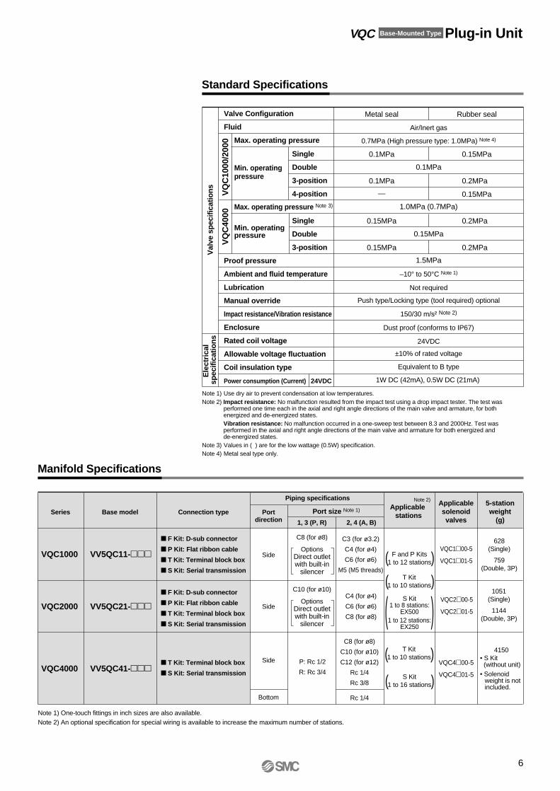
Standard Specifications
Manifold Specifications
Val
ve s
pec
ifica
tion
sE
lect
rica
l sp
ecifi
catio
ns
VQ
C10
00/2
000
VQ
C40
00
Single
Double
3-position
4-position
Single
Double
3-position
Valve Configuration
Fluid
Max. operating pressure
Max. operating pressure Note 3)
Min. operating pressure
Proof pressure
Ambient and fluid temperature
Lubrication
Manual override
Impact resistance/Vibration resistance
Enclosure
Rated coil voltage
Allowable voltage fluctuation
Coil insulation type
Power consumption (Current) 24VDC
Metal seal
0.1MPa
0.1MPa
—
0.15MPa
0.15MPa
Air/Inert gas
0.7MPa (High pressure type: 1.0MPa) Note 4)
0.1MPa
1.0MPa (0.7MPa)
0.15MPa
1.5MPa
–10° to 50°C Note 1)
Not required
Push type/Locking type (tool required) optional
150/30 m/s² Note 2)
Dust proof (conforms to IP67)
24VDC
±10% of rated voltage
Equivalent to B type
1W DC (42mA), 0.5W DC (21mA)
Rubber seal
0.15MPa
0.2MPa
0.15MPa
0.2MPa
0.2MPa
Note 1) Use dry air to prevent condensation at low temperatures.Note 2) Impact resistance: No malfunction resulted from the impact test using a drop impact tester. The test was
performed one time each in the axial and right angle directions of the main valve and armature, for both energized and de-energized states.Vibration resistance: No malfunction occurred in a one-sweep test between 8.3 and 2000Hz. Test was performed in the axial and right angle directions of the main valve and armature for both energized and de-energized states.
Note 3) Values in ( ) are for the low wattage (0.5W) specification.Note 4) Metal seal type only.
Series
F Kit: D-sub connector
P Kit: Flat ribbon cable
T Kit: Terminal block box
S Kit: Serial transmission
F Kit: D-sub connector
P Kit: Flat ribbon cable
T Kit: Terminal block box
S Kit: Serial transmission
Base model
VQC1000 VV5QC11-
VQC2000 VV5QC21-
T Kit: Terminal block box
S Kit: Serial transmissionVQC4000 VV5QC41-
Connection type
Piping specificationsApplicable
stations
Applicablesolenoidvalves
5-stationweight
(g)Port
direction
Side
Port size Note 1)
1, 3 (P, R)
C8 (for ø8)
OptionsDirect outletwith built-in
silencer
2, 4 (A, B)
C3 (for ø3.2)
C4 (for ø4)
C6 (for ø6)
M5 (M5 threads)
C8 (for ø8)
C10 (for ø10)
C12 (for ø12)
Rc 1/4
Rc 3/8
P: Rc 1/2
R: Rc 3/4
Rc 1/4
628(Single)
759(Double, 3P)
VQC100-5
VQC101-5
Note 2)
Side
Side
Bottom
C10 (for ø10)
OptionsDirect outletwith built-in
silencer
C4 (for ø4)
C6 (for ø6)
C8 (for ø8)
1051(Single)
1144(Double, 3P)
4150• S Kit (without unit)
• Solenoidweight is not included.
VQC200-5
VQC201-5
VQC400-5
VQC401-5
Note 1) One-touch fittings in inch sizes are also available.Note 2) An optional specification for special wiring is available to increase the maximum number of stations.
T Kit1 to 10 stations
( )S Kit1 to 16 stations
Min. operating pressure
VQC Base-Mounted Type Plug-in Unit

EX500-GAB1-X1
Rockwell⋅Automation PLC
57.6Kbit/sec, 115.2Kbit/sec230.4Kbit/sec
Gateway (GW) Unit
Input Block
Cables
Gateway type serial transmission system• Since wiring is "prepackaged" into one multi-connector type cable, wiring work is not only made
easier, but much more accurate.S Kit can be used by connecting to gateway unit.
S
7
Specifications
How to Order
ModelApplicable PLCCommunication protocol
Communication speed
Rated voltage
Current consumptionNumber of inputs/outputsNumber of input/outputbranchesBranch cableBranch cable lengthCommunication connectorPower connectorAmbient operating temperature and humidityEnclosureApplicable standard
Power supply voltage range
24VDC
200mA or less
Maximum 64 inputs/64 outputs
4 branches (16 inputs/16 outputs per branch)
8-core heavy-duty cable
5m or less (total extension 10m or less)
M12 connector (8-pin, socket)
M12 connector (5-pin, plug)
+5° to +45°C at 35% to 85% RH (no condensation)
IP65
UL, CSA, CE
EX500-GDN1
DeviceNet Release 2.0
125Kbit/sec, 250Kbit/sec500Kbit/sec
EX500-GPR1
PROFIBUS-DP
9.6, 19.2, 93.75, 187.5, 500Kbit/sec1.5, 3, 6, 12Mbit/sec
Input and control unit power supply: 24VDC ±10%Solenoid valve power supply: 24VDC +10%/–5% (with power drop warning at approx. 20V)
∗ Communication cables and communication connectors are sold separately.
EX500 G DN
DNPRAB
Communication protocolDeviceNet
PROFIBUS-DPRemote I/O (RIO)
Nil
-X1
Applicable GW unitDeviceNet
PROFIBUS-DP
Remote I/O (RIO)
1
How to Order Input Block
EX500 IE
Nil
-X1
Applicable GW unitDeviceNet
PROFIBUS-DPRemote I/O (RIO)
1
123456
Block typeM8 connector, PNP specificationsM8 connector, NPN specificationsM12 connector, PNP specificationsM12 connector, NPN specifications
8-point integrated type, M8 connector, PNP specifications8-point integrated type, M8 connector, NPN specifications
How to Order Input Manifold
EEX500 IB1
1
8
Stations1 station
8 stations
Nil
-X1
Applicable GW unitDeviceNet
PROFIBUS-DPRemote I/O (RIO)
E 8
⋅⋅⋅⋅⋅⋅
ETM
Connector typeM8 connectorM12 connector
M8 and M12 mixed
Input unit specifications
Input block specifications
Applicable sensor
Sensor connectorNumber of inputsRated voltageIndicationInsulationSensor supply current
Current source type (PNP output)or
Current sink type (NPN output)
M8 connector (3-pin) or M12 connector (4-pin)
2 inputs/8 inputs (M8 only)
24VDC
Green LED
None
Maximum 30mA/Sensor
How to Order Power Cable with Connector
EX500 AP S050
010050
Cable length1m5m
SA
Connector specificationsStraightAngle
How to Order Cable with M12 Connector
EX500 AC SSPS030
003005010030050
Cable length0.3m0.5m1m3m5m
Connector specifications
SSPS
SAPA
Socket side: StraightPlug side: Straight
Socket side: AnglePlug side: Angle
Input block specifications
Connection block
Communication connectorNumber of connection blocksBlock supply voltageBlock supply currentCurrent consumption
Short circuit protection
Current source type input block (PNP input block)or
Current sink type input block (NPN input block)
Operates at 1A Typ. (power supply cut)GW unit reset by turning power OFF and back ON.
M12 connector (8-pin, plug)
Maximum 8 blocks
24VDC
0.65A maximum
100mA or less (at rated voltage)
∗ With waterproof cap
2
3
45
6
7
18 1
7
65
4
3
28
Socket connectorpin arrangement
Plug connectorpin arrangement
Terminal no.Cable
core wire colors1 White
2 Brown3 Green
4 Yellow5 Gray
6 Pink7 Blue
1
357
8 Shield
2
46
8
Connections
2
4 3
5
Socket connectorpin arrangement
1 12
34
5
White: 24VDC +10%/-5% (solenoid valve power supply)
Black: 24VDC ±10% (input and control power supply)
Brown: 0V (solenoid valve power supply)
Blue: 0V (input and control power supply)
Gray: PE
Terminal no.
Cable core wire colors
Connections
EX500
Note) When ordering an input block manifold, enter theInput manifold part no. + Input block part no.together. The input block, end block and DIN railare included in the input manifold.
VQC1000/2000Kit (Serial Transmission Kit) Decentralized Serial wiring Conforms to IP67

8
VV5QC11S Kit (Serial Transmission Kit: EX500)
VV5QC21S Kit(Serial Transmission Kit: EX500)
nLL1L2L3L4
1 55.5104 125 135.5
266
114.5137.5148
3 76.5125 150 160.5
487
135.5162.5173
5 97.5146 175 185.5
6108 156.5187.5198
7118.5167 187.5198
8129 177.5200 210.5
9139.5188 212.5223
10150 198.5225 235.5
11160.5209 237.5248
12171 219.5250 260.5
13181.5230 250 260.5
14192 240.5262.5273
15202.5251 275 285.5
16213 261.5287.5298
nLL1L2L3L4
173
118 137.5148
289
134 150 160.5
3105 150 175 185.5
4121 166 187.5198
5137 182 200 210.5
6153 198 212.5223
7169 214 237.5248
8185 230 250 260.5
9201 246 262.5273
10217 262 287.5298
11233 278 300 310.5
12249 294 312.5323
13265 310 337.5348
14281 326 350 360.5
15297 342 362.5373
16313 358 375 385.5
Formulas: L1 = 10.5n + 45, L2 = 10.5n + 93.5 n: Stations (maximum 16 stations)
Formulas: L1 = 16n + 57, L2 = 16n + 102 n: Stations (maximum 16 stations)
M12Female thread
(12) 13
65
2n-C3, C4, C6, M5C3: ø3.2 One-touch fittingC4: ø4 One-touch fittingC6: ø6 One-touch fittingM5: M5 thread
DIN rail clamp screw
2-C81(P) port
2-C83(R) port
M12Male thread
0
1
9.5
25 40.5
20.5
34P = 10.5
62.5
60(1
2)
(7.5
) 7.5
18.5
n1 2 3 4 5 6 7StationsD-side 8 U-side
n1 2 3 4 5 6 7StationsD-side 8 U-side
DIN rail clamp screw
2n-C4, C6, C8
C6: ø6 One-touch fittingC8: ø8 One-touch fitting
C4: ø4 One-touch fitting
C103(R) port 2-C12
3(R) port
2-C121(P) port
C101(P) port
0
1
13.5
30 49.5
2545P = 16(7
.5)
10(1
2)25
6076.5
1376.5
(12)
Indicator lightManual override
Mounting hole for 4-M4
1.5P = 10.51.5
L128
(5.5
) (35) 66 7593
.537
.5
21
SI UNIT
SeriesEX 500
42.5L2
(L3)(L4)
7
Appr
ox. 9
Appr
ox. 2
Indicator lightManual override
Mounting hole for 4-M5
1138.5P = 1634.5
L1
(L3)(L4)
(5.5
)(3
5) 80
Appr
ox. 5
.510
5.5
Appr
ox. 1
0.5
(46.
5)12
7A
ppro
x. 3
.5
38.5
SI UNIT
SeriesEX500
L2
VQC1000/2000 Base-Mounted Type Plug-in Unit

Compatible network DeviceNet/PROFIBUS-DP
DeviceNet/PROFIBUS compatible SI unitAs a DeviceNet/PROFIBUS slave unit, this kit is capable of solenoid valve ON and OFF control up to 32 points. Furthermore, by connecting an input block, a maximum 32 sensor signal inputs are possible.
Input blockThis expansion block connects to the SI unit and allows for sensor input to the auto switches. Each input block can receive input from up to two or four sensors, and the common can be matched to the sensor by an NPN/PNP selector switch.Input connectors are available in both M8 and M12 types.
VQC1000/2000Kit (Serial Transmission Kit) for I/OS Conforms to IP67
9
2
1
3
4
5
BUS
PWR
0
1
R
P
12
X
3
1
0
1
0
1
2
3
0
1
2
3
1
4
2
3
5
2
1
3
4
5
2
1
3
4
5
4
3 1
Power connector: M12, 5 pins (Boss configuration differs from plug and communication connector.)Example of corresponding cable assemblies with connector:Hans Turck FmbH & Co. KG SAKW4.5T-2.
Input connector: M8, 3 pins (receptacle)Cable side connector example: Franz Binder GesmbH
718,768 series4-input block (EX250-IE3) No.
1
2
3
4
5
Description
SV24V
SV0V
SW24V
SW0V
E
Function
For solenoid valve +24V
For solenoid valve 0V
For sensor unit +24V
For sensor unit 0V
Ground
Description
PWR(V)
PWR
MOD/NET
ON when solenoid valve power supply is turned ON.
ON when DeviceNet circuit power supply input is turned ON.
OFF: Power supply off, off line, or when checking duplication of MAC_ID.
GREEN BLINKING: Waiting for connection (on line).
GREEN ON: Connection established (on line).
RED BLINKING: Connection time out (minor communication abnormality).
RED ON: MAC_ID duplication error, or BUSOFF error(major communication abnormality).
Description Function
ON when sensor power is turned ON.
ON when each sensor input goes ON.
Input connector: M12, 5 pins (receptacle)Cable side connector example: OMRON Corporation XS2G
2-input block (EX250-IE1)4-input block (EX250-IE2)
No.
1
2∗
3
4
5
Description
SW+
N.C. (SIGNAL)
SW–
SIGNAL
E
Function
(+) Sensor power supply
Open
(–) Sensor power supply
Sensor input signal
Sensor ground
No.
1
3
4
Description Function
(+) Sensor power supply
(–) Sensor power supply
Sensor input signal
Communication connector DeviceNet: M12, 5 pins (for plug and DeviceNet only)Example of corresponding cable assemblies with connector:
OMRON Corporation DCA1-5CN05F1, Karl Lumberg GmbH & Co. KG RKT5-56
Communication connector (PROFIBUS-DP): M12, 5 pins (plug)
No.
1
2
3
4
5
Description
Drain
V+
V–
CAN_H
CAN_L
Function
Drain/Shield
(+) Circuit power supply
(–) Circuit power supply
Signal H
Signal L
SI unit (DeviceNet)
SI unit (PROFIBUS-DP)
Input block
Indicator Unit (LED) Description and Function
Connector Details
∗ In the case of 4-input block unit (EX250-IE2), this is the sensor input signal.
∗ Contact your SMC representative for specifications and handling precautions.
No.
1
2
3
4
5
Description Function
Description
PWR(V)
RUN
DIA
BF
ON when solenoid valve power supply is turned ON.OFF when the power supply voltage is less than 19V.
ON when operating (SI unit power supply is ON).
ON when the self diagnosis device detects abnormality.
ON for BUS abnormality.
PWR
0
1
2
3
EX250
SETTINGS
1
PWR(V) PWR MOD/NET
0
EX250
2-input type(EX250-IE1)
1
0
PWR
EX250
4-input type(EX250-IE2/3)
24V
0V
IN
VP
R x D/T x D(N)
DGND
R x D/T x D(P)
SHIELD
Terminal +5V
Signal –N
GND terminal
Signal –P
Shield ground
PWR
0 to 1(3)
Function
Function
• The serial transmission system greatly reduces connection work, minimizes wiring, and saves space.

n1 2 3 4 5 6 7StationsD-side 8 U-side
n1 2 3 4 5 6 7StationsD-side 8 U-side
10
VV5QC11S Kit(Serial Transmission Kit: EX250)
VV5QC21S Kit(Serial Transmission Kit: EX250)
nLL1L2L3L4
1 55.5178 200 210.5
266
188.5212.5223
3 76.5199 225 235.5
487
209.5237.5248
5 97.5220 250 260.5
6108 230.5250 260.5
7118.5241 262.5273
8129 251.5275 285.5
9139.5262 287.5298
10150 272.5300 310.2
11160.5283 312.5323
12171 293.5325 335.5
13181.5304 325 335.5
14192 314.5337.5348
15202.5325 350 360.5
16213 335.5362.5373
17223.5346 375 385.5
18 234 356.5387.5398
19244.5367 387.5398
20255 377.5400 410.5
21265.5388 412.5423
22276 398.5425 435.5
23286.5409 437.5448
24297 419.5450 448
Formulas: L1 = 10.5n + 45, L2 = 10.5n + 167.5 (for 1 input block. For each additional input block, add 21mm.) n: Stations (maximum 24 stations)
nLL1L2L3L4
173
192 212.5223
289
208 237.5248
3105 224 250 260.5
4121 240 262.5273
5137 256 275 285.5
6153 272 287.5298
7169 288 312.5323
8185 304 325 335.5
9201 320 337.5348
10217 336 362.5373
11233 352 375 385.5
12249 368 387.5398
13265 384 400 410.5
14281 400 425 435.5
15297 416 437.5448
16313 432 450 460.5
17329 448 462.5473
18345 464 487.5498
19361 480 500 510.5
20377 496 512.5523
21393 512 537.5548
22409 528 550 560.5
23425 544 562.5573
24441 560 587.5598
Formulas: L1 = 16n + 57, L2 = 16n + 176 (for 1 input block. For each additional input block, add 21mm.) n: Stations (maximum 24 stations)
Manual overrideIndicator light
Mounting holefor 4-M5
1138.5P = 1634.5
L1
(5.5
)
(35) 80 10
5.5
App
rox.
5.5
Appr
ox. 1
0.5
127
Appr
ox. 3
.5
63211075.5
L2
(46.
5)
(L3)(L4)
DIN rail clamp screw
2-C83(R) port
4-M82-M12
M3
0BUS
PWR
1
2
3
9.5
25 40.5
20.534P = 10.5
62.5
60(1
2)
(7.5
) 7.5
18.5
Indicator lightManual override
Mounting hole for 6-M4
SI unit
Input block
1.5P = 10.5
1.5
L128
(5.5
)(3
5) 66 75
21 63111
L25.5
93.5
37.5
(L3)(L4)
Appr
ox. 2
Appr
ox. 4
(12) 1365
2n-C3, C4, C6, M5C3: ø3.2 One-touch fittingC4: ø4 One-touch fittingC6: ø6 One-touch fittingM5: M5 thread
2n-C4, C6, C8C4: ø4 One-touch fittingC6: ø6 One-touch fittingC8: ø8 One-touch fitting
2-C81(P) port
(12) 1376.5
2-C123(R) port
2-C121(P) port
DIN rail clamp screw
C103(R) port
C101(P) port
13.5
30 49.5
2545P = 16
1025
76.5
60
(12)
(7.5
)
BUS
PWR
VQC1000/2000 Base-Mounted Type Plug-in Unit

Compatible network DeviceNet/PROFIBUS-DP
DeviceNet/PROFIBUS compatible SI unitAs a DeviceNet/PROFIBUS slave unit, this kit is capable of solenoid valve ON and OFF control up to 32 points. Furthermore, by connecting a maximum of 4 input blocks, up to 32 sensor signal inputs are possible.
Input blockThis expansion block connects to the SI unit and allows for sensor input to the auto switches. Each input block can receive input from up to 8 sensors, and the common can be matched to the sensor by an NPN/PNP selector switch.
SI unit (DeviceNet) SI unit (PROFIBUS-DP) Input block
Indicator Unit (LED) Descriptions and Functions
Connector Details
VQC4000Kit (Serial Transmission Kit) for I/O Conforms to IP67S
11
PWR
SI UNIT
PWR(V) MOD/NET
1
SETTINGS
0
1
2
4
3
5
5
4
3
1
2
1
2
34
5
• Input connector: M12, 5 pins (OMRON Corporation XS2F compatible) x 8 pcs. Cable side connector example: OMRON Corporation XS2G
SW + SIGNAL -n + 1
SW–SIGNAL -n
PE
No.
1
2
3
4
5
Description
SW +
N.C.
SW –
SIGNAL
PE
Function(+) Sensor power supply
Open∗
(–) Sensor power supply
Sensor input signal
Protective sensor ground
∗ The second pin of the connector with input no. 0, 2, 4, 6 (the connector at the right side of the input block) is connected internally to the fourth pin (sensor input no.) of the connector with input no. 1, 3, 5, 7. This makes it possible to directly input two inputs that are combined together by the common connector.
• Power connector: Franz Binder GesmbH Series723, 5 pins (72309-0115-80-05)Cable side connector example: Franz Binder GesmbH 72309-0114-70-15, etc.∗ DIN type 5 pins
• Communication connector (DeviceNet): M12, 5 pins (for DeviceNet only)Example of corresponding cable assemblies with connector:OMRON Corporation DCA1-5CN05F1, Karl Lumberg GmbH & Co. KG RKT5-56.
No.
1
2
3
4
5
Description
SV24V
SV0V
PE
SW24V
SW0V
Function
For solenoid valve +24V
For solenoid valve 0V
Protective ground
For solenoid valve +24V
For solenoid valve 0V
No.
1
2
3
4
5
Description
Drain
V +
V –
CAN_H
CAN_L
Function
Drain/Shield
(+) Circuit power supply
(–) Circuit power supply
Signal H
Signal L
Compatible with DeviceNet specification Micro Style connector.
• Communication connector (PROFIBUS-DP):CONINVERS® RC-2RS1N12, 12 pinsCable side connector example: Siemens AG 6ES5 760-2CB11
No.
1
2
4
6
9
12
Description
M5V
A
B
+5V
SHIELD
RTS
Function
GND Terminal
Signal –N
Signal –P
Terminal +5V
Shield ground
Optical fiber (reserve)
Input block SI unit (DeviceNet) SI unit (PROFIBUS-DP)
Input connector
Communicationconnector
Power connector
12345
12345
Connector: Input no. 0, 2, 4, 6 Input no. 1, 3, 5, 7
When IP65 or equivalent enclosures are required, install a waterproof cover on the input connector that is not being used. Order waterproof covers separately.Example: OMRON Corporation XS2Z-12
Caution
Description
PWR(V)
PWR
MOD/NET
Function
ON when solenoid valve power supply is turned ON.
ON when DeviceNet circuit power supply input is turned ON.
OFF: Power supply off, off line, or when checking duplication of MAC_ID.
GREEN BLINKING: Waiting for connection (on line).
GREEN ON: Connection established (on line).
RED BLINKING: Connection time out (minor communication abnormality).
RED ON: MAC_ID duplication error, or BUSOFF error(major communication abnormality).
Description Function
PWR(V)
RUN
DIA
BF
ON when solenoid valve power supply is turned ON.
OFF when the power supply voltage is less than 19V.
ON when operating (SI unit power supply is ON).
ON when self diagnosis device detects abnormality.
ON for BUS abnormality.
Description
PWR
0 to 7
Function
ON when sensor power is turned ON.
OFF when short circuit protection is working.
ON when each sensor input goes ON.
129
1
2
4
6
PWR(V) MOD/NETPWR
1
0
TMTM
FB
PS
SETTINGS
ADDRESS
H
DIA BF
L
PWR(V) RUN
FB
PS
0246
1357
PWR
• The serial transmission system greatly reduces connection work, minimizes wiring, and saves space.
• Pin no. 3, 5, 7, 8, 10 and 11 marked with "" are open.
∗ The connector configuration and the pin arrangement are compatible with Siemens AG ET200C.

12
VV5QC41S Kit (Serial Transmission Kit: EX240)
nLL1L2
1131266
2156291
3181316
4206341
5231366
6256391
7281416
8306441
9331466
10356491
11381516
12406541
13431566
14456591
15481616
16506641
Formulas: L1 = 25n + 106, L2 = 25n + 241 (for 1 input block. For each additional input block, add 54mm.) n: Stations (maximum 16 stations)
101
1014
3
3298
.8
143
99
163
14.5
(128.5)
54 P = 25
ABABABABAAA B
65.5
L18 6.5
L2 (1 input block: 8 inputs)
Min.0 to Max. 4unit
(0 to 216mm)
Indicator light
Manual override
Mounting hole for 2-M5, with input block onlyInput block
SI unit
75.5
61.5
1.5
1220
.5
43.5
11.5 21.5 (6.5)
2731
38.5
77.5 95
.5
8
23
2-Rc 1/8(External pilot port)
2-Rc 1/4, 3/8, C8, C10, C12(2(B), 4(A) port)
2-Rc 1/8(Pilot EXH port)
2-Rc 3/43(R) port
2-Rc 1/21(P) port
n1 2 3 4 5 6 7StationsD-side 8 U-side
VQC4000 Base-Mounted Type Plug-in Unit

F
13
Note) When using the negative COM specification, use valves for negative COM.
Cable assemblyElectrical wiring specifications
1 (–) (+) Black NoneSOL. A
SOL. B
SOL. A
SOL. B
SOL. A
SOL. B
SOL. A
SOL. B
SOL. A
SOL. B
SOL. A
SOL. B
SOL. A
SOL. B
SOL. A
SOL. B
SOL. A
SOL. B
SOL. A
SOL. B
SOL. A
SOL. B
SOL. A
SOL. B
COM
14 (–) (+) Yellow BlackStation 1
Station 2
Station 3
Station 4
Station 5
Station 6
Station 7
Station 8
Station 9
Station 10
Station 11
Station 12
2 (–) (+) Brown None
15 (–) (+) Pink Black
3 (–) (+) Red None
16 (–) (+) Blue White
4 (–) (+) Orange None
17 (–) (+) Purple None
5 (–) (+) Yellow None
18 (–) (+) Gray None
6 (–) (+) Pink None
19 (–) (+) Orange Black
7 (–) (+) Blue None
20 (–) (+) Red White
8 (–) (+) Purple White
21 (–) (+) Brown White
9 (–) (+) Gray Black22 (–) (+) Pink Red
10 (–) (+) White Black
23 (–) (+) Gray Red11 (–) (+) White Red
24 (–) (+) Black White
12 (–) (+) Yellow Red
25 (–) (+) White None
13 (+) (–) Orange Red
PolarityTerminalno.
Lead wirecolor
Dotmarking
PositiveCOMspec.
NegativeCOMspec.
D-sub connector
Lead wire colors forD-sub connector assemblies
(AXT100-DS25- )
As the standard electrical wiring specification used is for 12 stations or less, double wiring (connected to SOL. A and SOL. B) is used for the internal wiring of each station regardless of valve and option types.Mixed single and double wiring are available as options.Refer to special wiring specifications (options) below.
Mixed single and double wiring are available as options. The maximum number of manifold stations is determined by the number of solenoids. Count one point for a single solenoid type and two points for a double solenoid type. The total number of solenoids (points) must not exceed 24.
015030050
12345678910111213
141516171819202122232425
Connector terminal no.
12345678910111213
141516171819202122232425
COM
(For 25P)
D-side
1 2 3⋅⋅⋅⋅⋅⋅⋅⋅⋅⋅⋅⋅s
tations
AXT100-DS25-015030050
Lead wire colors forD-sub connectorcable assemblyterminal numbers
Terminalno.12345678910111213141516171819202122232425
Lead wirecolorBlackBrownRed
OrangeYellowPinkBlue
PurpleGrayWhiteWhiteYellowOrangeYellowPinkBlue
PurpleGray
OrangeRed
BrownPinkGrayBlackWhite
Dotmarking
NoneNoneNoneNoneNoneNoneNoneWhiteBlackBlackRedRedRed
BlackBlackWhiteNoneNoneBlackWhiteWhiteRedRed
WhiteNone
D-sub connector cable assemblies (optional)
Electrical characteristics
Cablelength (L) Part no. Note
1.5m3m5m
AXT100-DS25-015AXT100-DS25-030AXT100-DS25-050
Cable0.3mm² x 25 cores
Item Characteristic
Conductor resistanceΩ/km, 20°CWithstand pressureV, 1 minute, AC
Insulation resistanceMΩ/km, 20°C
65 or less
1000
5 or more
Some connector manufacturers:
• Fujitsu, Ltd.• Japan Aviation Electronics Industry, Ltd.• J.S.T. Mfg. Co., Ltd.• HIROSE ELECTRIC CO., LTD.
Cable0.3mm² x 25 coresO.D. ø1.4
Seal (length indication)
Connector DB-25SF-Nmanufactured byJapan AviationElectronics Industry, Ltd.
Socket side
Terminal no.
Approx. ø10
47.04
55
1644
8(2
.4)
L
1⋅⋅⋅⋅⋅⋅⋅⋅⋅⋅13
14⋅⋅⋅⋅⋅⋅⋅⋅⋅⋅25
Molded cover
2-M2.6 x 0.45
SMC
015
Special wiring specifications (options)
• Using our D-sub connector for electrical connections greatly reduces labor, while it also minimizes wiring and saves space.
• We use a D-sub connector (25P) that conforms to MIL standards and is therefore widely compatible with many standard commercial models.
• Top or side entry for the connector can be changed freely, allowing for changes even after mounting, to meet any changing needs for space.
D-sub connector cable assemblies can be ordered with manifolds. Refer to manifold ordering.
∗ When using a standard commercial connector, use a type 25P female connector conforming to MIL-C-24308.
∗ Cannot be used for transfer wiring.
Note) The minimum bending radius for D-sub connector cables is 20mm.
U-side
Note)
VQC1000/2000Kit (D-sub Connector Kit) Conforms to IP40

14
VV5QC11
nLL1L2L3L4
1 55.5112.5137.5148
266
123 150 160.5
3 76.5133.5162.5173
487
144 175 185.5
5 97.5154.5175 185.5
6108 165 187.5198
7118.5175.5200 210.5
8129 186 212.5223
9139.5196.5225 235.5
10150 207 237.5248
11160.5217.5237.5248
12171 228 250 260.5
13181.5238.5262.5273
14192 249 275 285.5
15202.5259.5287.5298
16213 270 300 310.5
17223.5280.5300 310.5
18234 291 312.5323
19244.5301.5325 335.5
20255 312 337.5348
21265.5322.5350 360.5
22276 333 362.5373
23286.5343.5375 385.5
24297 354 375 385.5
Formulas: L1 = 10.5n + 45, L2 = 10.5n + 102 n: Stations (maximum 24 stations)
2n-C3, C4, C6, M5C3: ø3.2 One-touch fittingC4: ø4 One-touch fittingC6: ø6 One-touch fittingM5: M5 thread
2-C83(R) port
2-C81(P) port
DIN rail clamp screw
(7.5
)7.
518
.5
9.5
25 40.5
(12)
20.5
34P = 10.5
356062
.5
Manual override
Indicator light
Manual release for switching connector direction
Mounting hole for 4-M4
1.5P = 10.5
1.5
L1L2
51
(L3)(L4)
28
(5.5
)
(35)
37.5
93.5
Appr
ox. 2
66 75
n1 2 3 4 5 6 7StationsD-side 8 U-side
n1 2 3 4 5 6 7StationsD-side 8 U-side
VV5QC21
Manual override
Indicator light
Mounting hole for 4-M5Release for switching connector direction
11 38.5P = 16
34.5L147
L2(L3)(L4)
(5.5
)
(35) 80 10
5.5
Appr
ox. 5
.5Ap
prox
. 10.
5
(46.
5)
127
Appr
ox. 3
.5 50.5
173
126.5150 160.5
289
142.5162.5173
3105 158.5187.5198
4121 174.5200 210.5
5137 190.5212.5223
6153 206.5237.5248
7169 222.5250 260.5
8185 238.5262.5273
9201 254.5275 285.5
10217 270.5300 310.5
11233 286.5312.5323
12249 302.5325 335.5
13 265 318.5350 360.5
14281 334.5362.5373
15297 350.5375 385.5
16313 366.5387.5398
17329 382.5412.5423
22409 462.5487.5498
18345 398.5425 435.5
21393 446.5475 485.5
23425 478.5500 510.5
24441 494.5525 535.5
19361 414.5437.5448
20377 430.5450 460.5
nLL1L2L3L4
Formulas: L1 = 16n + 57, L2 = 16n + 110.5 n: Stations (maximum 24 stations)
Applicable connector: D-sub connector (25P)(Conforms to MIL-C-24308)
(12) 1365
Applicable connector: D-sub connector (25P)
(Conforms to MIL-C-24308)
1376.5
(12)
2n-C4, C6, C8C4: ø4 One-touch fittingC6: ø6 One-touch fittingC8: ø8 One-touch fitting
2-C123(R) port
2-C121(P) port
DIN rail clamp screw
C103(R) port
C101(P) port 13
.530 49
.5
2545P = 16
(7.5
)10
(12)
25356076
.5
VQC1000/2000 Base-Mounted Type Plug-in Unit

VQC1000/2000Kit (Flat Ribbon Cable Kit) Conforms to IP40P
15
Cable assemblyElectrical wiring specifications
Mixed single and double wir-ing are available as options. The maximum number of manifold stations is deter-mined by the number of sol-enoids. Count one point for a single solenoid type and two points for a double solenoid type. The total number of solenoids (points) must not exceed 24.
D-side1 2 3⋅⋅⋅⋅⋅⋅⋅
⋅⋅⋅⋅⋅stations
AXT100-FC -123
2026
Flat ribbon cable connector assemblies (optional)Cablelength (L)
Part no.
1.5m3m5m
26PAXT100-FC26-1AXT100-FC26-2AXT100-FC26-3
20PAXT100-FC20-1AXT100-FC20-2AXT100-FC20-3
Some connector manufacturers:
• HIROSE ELECTRIC CO., LTD.• Sumitomo/3-M Limited• Fujitsu, Ltd.• Japan Aviation Electronics Industry, Ltd.• J.S.T. Mfg. Co., Ltd.• Oki Electric Cable Co., Ltd.
6
(15.6)
L
Terminal no.
Red
28AWG
30
(20P
)37
.5 (
26P
)
262
251
Note) When using the negative COM specification, use valves for negative COM.
Flat ribbon cable connector
<26P> <20P>
Connector terminal number
26
24
22
20
18
16
14
12
10
8
6
4
2
25
23
21
19
17
15
13
11
9
7
5
3
1
Triangle mark indicator position
Double wiring (connected to SOL. A and SOL. B) is used for the internal wiring of each station regardless of valve and option types.Mixed single and double wiring are available as options.Refer to special wiring specifica-tions (options) below.
1
2
3
4
5
6
7
8
9
10
11
12
13
14
15
16
17
18
19
20
21
22
23
24
25
26
1
2
3
4
5
6
7
8
9
10
11
12
13
14
15
16
17
18
19
20
SOL. A
SOL. B
SOL. A
SOL. B
SOL. A
SOL. B
SOL. A
SOL. B
SOL. A
SOL. B
SOL. A
SOL. B
SOL. A
SOL. B
SOL. A
SOL. B
SOL. A
SOL. B
SOL. A
SOL. B
SOL. A
SOL. B
SOL. A
SOL. B
COM
COM
Station 1
Station 2
Station 3
Station 4
Station 5
Station 6
Station 7
Station 8
Station 9
SOL. A
SOL. B
SOL. A
SOL. B
SOL. A
SOL. B
SOL. A
SOL. B
SOL. A
SOL. B
SOL. A
SOL. B
SOL. A
SOL. B
SOL. A
SOL. B
SOL. A
SOL. B
COM
COM
Station 1
Station 2
Station 3
Station 4
Station 5
Station 6
Station 7
Station 8
Station 9
Station 10
Station 11
Station 12
(–)
(–)
(–)
(–)
(–)
(–)
(–)
(–)
(–)
(–)
(–)
(–)
(–)
(–)
(–)
(–)
(–)
(–)
(–)
(–)
(–)
(–)
(–)
(–)
(+)
(+)
(+)
(+)
(+)
(+)
(+)
(+)
(+)
(+)
(+)
(+)
(+)
(+)
(+)
(+)
(+)
(+)
(+)
(+)
(+)
(+)
(+)
(+)
(+)
(+)
(–)
(–)
Terminalno.
(–)
(–)
(–)
(–)
(–)
(–)
(–)
(–)
(–)
(–)
(–)
(–)
(–)
(–)
(–)
(–)
(–)
(–)
(+)
(+)
Polarity
PositiveCOMspec.
NegativeCOMspec.
(+)
(+)
(+)
(+)
(+)
(+)
(+)
(+)
(+)
(+)
(+)
(+)
(+)
(+)
(+)
(+)
(+)
(+)
(–)
(–)Positive
COMspec.
NegativeCOMspec.
26
24
22
20
18
16
14
12
10
8
6
4
2
25
23
21
19
17
15
13
11
9
7
5
3
1
COM COM
(For 26P)
20
18
16
14
12
10
8
6
4
2
19
17
15
13
11
9
7
5
3
1
COM COM
(For 20P)
Special wiring specifications (options)
U-side
• Using our flat ribbon cable for electrical connections greatly reduces labor, while it also minimizes wiring and saves space.
• We use flat ribbon cables whose connectors (26P and 20P) conform to MIL standards, and are therefore widely compatible with many standard commercial models.
• Top or side entry for the connector can be changed freely, allowing for changes even after mounting, to meet any changing needs for space.
Terminalno.
Polarity
Type 26P flat ribbon cable connector assemblies can be ordered with manifolds. Refer to manifold ordering.
∗ When using a standard commercial connector, use a type 26P connector conforming to MIL-C-83503 or a type 20P with strain relief.
∗ Cannot be used for transfer wiring.

nLL1L2L3L4
173
126.5150 160.5
289
142.5162.5173
3105 158.5187.5198
4121 174.5200 210.5
5137 190.5212.5223
6153 206.5237.5248
7169 222.5250 260.5
8185 238.5262.5273
9201 254.5275 285.5
10217 270.5300 310.5
11233 286.5312.5323
12249 302.5325 335.5
13265 318.5350 360.5
14281 334.5362.5373
15297 350.5375 385.5
16313 366.5387.5398
17329 382.5412.5423
18345 398.5425 435.5
19361 414.5437.5448
20377 430.5450 460.5
21393 446.5475 485.5
22409 462.5487.5498
23425 478.5500 510.5
24441 494.5525 535.5
Formulas: L1 = 16n + 57, L2 = 16n + 110.5 n: Stations (maximum 24 stations)
16
VV5QC11
nLL1L2L3L4
1 55.5112.5137.5148
266
123 150 160.5
3 76.5133.5162.5173
487
144 175 185.5
5 97.5154.5175 185.5
6108 165 187.5198
7118.5175.5200 210.5
8129 186 212.5223
9139.5196.5225 235.5
10150 207 237.5248
11160.5217.5237.5248
12171 228 250 260.5
13181.5238.5262.5273
14192 249 275 285.5
15202.5259.5287.5298
16213 270 300 310.5
17223.5280.5300 310.5
18234 291 312.5323
19244.5301.5325 335.5
20255 312 337.5348
21265.5322.5350 360.5
22276 333 362.5373
23286.5343.5375 385.5
24297 354 375 385.5
Formulas: L1 = 10.5n + 45, L2 = 10.5n + 102 n: Stations (maximum 24 stations)
VV5QC21
Indicator lightManual override
Mounting hole for 4-M4Manual release for switching connector direction
P = 10.51.5
1.5
L1L2
51
(L3)(L4)
28
(5.5
)
(35)
37.5
93.5
Appr
ox. 2
66 75
Manual overrideIndicator light
Mounting hole for 4-M5Manual release for switching connector direction
1138.5P = 1634.5
L147L2
(L3)(L4)
(5.5
)
(35) 80 10
5.5
Appr
ox. 5
.5Ap
prox
. 10.
5
(46.
5)
127
Appr
ox. 3
.5 50.5
Applicable connector:Flat ribbon cable connector (26P)(Conforms to MIL-C-83503 )
(12) 13
65
2-C83(R) port
2-C81(P) port
DIN rail clamp screw
(7.5
)7.
5
18.5
9.5
25 40.5
(12)
20.534P = 10.5
356062
.5
2n-C3, C4, C6, M5C3: ø3.2 One-touch fittingC4: ø4 One-touch fittingC6: ø6 One-touch fittingM5: M5 thread
n1 2 3 4 5 6 7StationsD-side 8 U-side
1376.5
(12)
Applicable connector:Flat ribbon cable connector (26P)(Conforms to MIL-C-83503 )
2n-C4, C6, C8C4: ø4 One-touch fittingC6: ø6 One-touch fittingC8: ø8 One-touch fitting
DIN rail clamp screw
C103(R) port
C101(P) port
2-C123(R) port
2-C121(P) port
13.5
30 49.5
2545P = 16(7
.5)
10(1
2)
2535
6076.5
n1 2 3 4 5 6 7StationsD-side 8 U-side
VQC1000/2000 Base-Mounted Type Plug-in Unit

• This kit has a small terminal block inside a junction box. The provision of a G3/4 electrical entry allows connection of conduit fittings.
VQC1000/2000/4000Kit (Terminal Block Box Kit) Conforms to IP67T
17
SOL. A1A (–) (+)
SOL. B1B (–) (+)
Station 1
SOL. A2A (–) (+)
SOL. B2B (–) (+)
Station 2
SOL. A3A (–) (+)
SOL. B3B (–) (+)
Station 3
SOL. A4A (–) (+)
SOL. B4B (–) (+)
Station 4
SOL. A5A (–) (+)
SOL. B5B (–) (+)
Station 5
SOL. A6A (–) (+)
SOL. B6B (–) (+)
Station 6
SOL. A7A (–) (+)
SOL. B7B (–) (+)
Station 7
SOL. A8A (–) (+)
SOL. B8B (–) (+)
Station 8
SOL. A9A (–) (+)
SOL. B9B (–) (+)
Station 9
SOL. A10A (–) (+)
SOL. B10B (–) (+)
Station 10
(+) (–)
Terminalno.
Polarity
PositiveCOM
NegativeCOM
Electrical wiring specifications (conforms to IP67)
COM
Standard wiring
The internal wiring is double (con-nected to SOL. A and SOL. B) for all stations regardless of the type of valve or options.Mixed single and double wiring are available as options.
Note) There is no polarity. This de-vice can also be used as a negative common.
1ACOM
2A3A
4A5A
6A7A
8A9A
10A
1B2B
3B4B
5B6B
7B8B
9B10B
1B1A
2B2A
3B3A
4B4A
5B5A
6B6A
7B7A
8B8A
9B9A
10B10A
COM
1ACOM
2A3A
4A5A
6A7A
8A9A
10A
1B2B
3B4B
5B6B
7B8B
9B10B
1B1A
2B2A
3B3A
4B4A
5B5A
6B6A
7B7A
8B8A
9B9A
10B10A
COM
Terminal Block Connection
Proper tightening torque (N⋅m)
0.7 to 1.2
Mounting screw (M4)Terminal block cover
Gasket
Electrical entry2-G3/4
M3 screw
6mm
Step 3. How to replace the terminal block coverSecurely tighten the screws to the torque shown in the table below, after confirming that the gasket is installed correctly.
Step 1. How to remove terminal block coverLoosen the 4 mounting screws (M4) and remove the terminal block cover.
Step 2. The diagram below shows the terminal block wiring. All stations are provided with double wiring regardless of the valves which are mounted.Connect each wire to the power supply side, according to the markings provided inside the terminal block.
Special wiring specifications (options)
Mixed single and double wiring are available as options. The maximum number of manifold stations is determined by the number of solenoids. Count one point for a single solenoid type and two points for a double solenoid type. The total number of solenoids (points) must not exceed 20.
1. How to orderIndicate option symbol "-K" in the manifold part number and be sure to specify station positions for single or double wiring on the manifold specification sheet.
2. Wiring specificationsConnector terminal numbers are connected from solenoid station 1 on the A side in the order indicated by the arrows without skipping any terminal numbers.
• Applicable crimp terminal (fork tongue type): 1.25-3S, 1.25Y-31.25Y-3N, 1.25Y-3.5

18
VV5QC11
nLL1L2L3L4
1 55.5165 187.5198
266
175.5200 210.5
3 76.5186 212.5223
487
196.5212.5223
5 97.5207 225 235.5
6108 217.5237.5248
7118.5228 250 260.5
8129 238.5262.5273
9139.5249 275 285.5
10150 259.5275 285.5
11160.5270 287.5298
12171 280.5300 310.5
13181.5291 312.5323
14192 301.5325 335.5
15202.5312 337.5348
16213 322.5337.5348
17223.5333 350 360.5
18234 343.5362.5373
19244.5354 375 385.5
20255 364.5387.5398
Formulas: L1 = 10.5n + 45, L2 = 10.5n + 154.5 n: Stations (maximum 20 stations)
nLL1L2L3L4
173
179 200 210.5
289
195 212.5223
3105 211 237.5248
4121 227 237.5248
5137 243 262.5273
6153 259 262.5273
7169 275 287.5298
8185 291 312.5323
9201 307 325 335.5
10217 323 371 360.5
11233 339 362.5373
12249 355 375 385.5
13265 371 408.5398
14281 387 412.5423
15297 403 425 435.5
16313 419 437.5448
17329 435 462.5473
18345 451 496 485.5
19361 467 487.5498
20377 483 500 510.5
Formulas: L1 = 16n + 57, L2 = 16n + 163 n: Stations (maximum 20 stations)
(12) 1376.5
Manual override
Indicator light
Mounting hole for 4-M4
1.5
P = 10.5
1.5
L1
28
(5.5)
(35) 93
.5Ap
prox
. 2
66 75
L2
103
(L3)(L4)
7
80126
(12) 13
2-C83(R) port
2-C81(P) port
DIN rail clamp screw
2n-C3, C4, C6, M5C3: ø3.2 One-touch fittingC4: ø4 One-touch fittingC6: ø6 One-touch fittingM5: M5 thread
2-G3/4Conduit port
9.5
25 40.5
20.5
34P = 10.5
(7.5
)
18.7
7.7
(12)
77.7
2-C123(R) port
2-C121(P) port
DIN rail clamp screw
C103(R) port
C101(P) port
2-G3/4Conduit port
13.5
30 49.5
2545P = 16(7
.5)
1012
2577
.5
2n-C4, C6, C8C4: ø4 One-touch fittingC6: ø6 One-touch fittingC8: ø8 One-touch fitting
VV5QC21
Manual override
Indicator light
Mounting hole for 4-M5
1138.5P = 16
L1
(5.5
)(3
5) 80 105.
5
Appr
ox. 5
.5
Appr
ox. 1
0.5
127
Appr
ox. 3
.5(4
6.5)
99
(L3)(L4)
L2
7
80
n1 2 3 4 5 6 7StationsD-side 8 U-side
n1 2 3 4 5 6 7StationsD-side 8 U-side
VQC1000/2000 Base-Mounted Type Plug-in Unit

n1 2 3 4 5 6 7StationsD-side 8 U-side
19
TVV5QC41
nLL1L2
1131217
2156242
3181267
4206292
5231317
6256342
7281367
8306392
9331417
10356442
11381467
12406492
13431517
14456542
15481567
16506592
17531617
18556642
19581667
20606692
Formulas: L1 = 25n + 106, L2 = 25n + 192 n: Stations (maximum 20 stations)
101
80 143
163
99
7
79.5 L1
ABABABABAAA B
6.5
65.5P = 25
L2
34.5
Indicator light
Manual override
12 20.5
43.5 77
.5 95.5
(6.5)
11.5
21.5
27
31
38.7
2-Rc 3/43(R) port
2-Rc 1/8(External pilot port)
2-Rc 1/4, 3/8, C8, C10, C12(2(B), 4(A) port)
2-Rc 1/8(Pilot EXH port)
2-Rc 1/21(P) port
Mounting holefor 2-M5
VQC1000/2000/4000Kit (Terminal Block Box Kit) Conforms to IP67

20

21
Manifold Exploded View
Manifold block assemblyD-side end plate assembly U-side end plate assemblyHousing assembly and SI unit
VQC1000VQC2000
VQC1000VQC2000
VQC4000
VQC1000VQC2000
VQC1000VQC2000
VQC1000VQC2000VQC4000
i
o
!0
y t
u
EX500
ÇìÇÖÇíÇâÇÖÇì
r
!1
!3
!2
e
q
w
Note) Drawing shows VQC1000 type.
T K
it(T
erm
inal
blo
ck)
P K
it(F
lat r
ibbo
n ca
ble)
F K
it(D
-sub
con
nect
or)
S K
it (S
eria
l)EX
250
EX50
0EX
240

OptionsNilR
S
Centralized exhaustExternal pilotDirect exhaust outlet with built-in silencer
Note) Tie-rods (2 pcs.) for additional sta-tions included.
VQC Base-Mounted Type Manifold Exploded View
22
Housing assembly and SI unit/Input block
D-side end plate assembly Manifold block assembly
Manifold Assembly Part No.
Description NoteApplicable model
DeviceNet (–COM)
PROFIBUS-DP (–COM)
M12, 2 inputs
M12, 4 inputs
M8, 4 inputs
1: Standard 2: DIN rail mounting
DeviceNet ( +COM)
Remote I/O (+COM)
DeviceNet (–COM)
Remote I/O (–COM)
DeviceNet (+COM)
PROFIBUS-DP (–COM)
M12, 8 inputs
For manifold with input block
For manifold without input block
F Kit, 25-pin
P Kit, 26-pin
P Kit, 20-pin
T Kit
Part no.
EX250-SDN1EX250-SPR1EX250-IE1EX250-IE2EX250-IE3EX250-EAEX500-Q001EX500-Q001-X1EX500-Q101EX500-Q101-X1EX240-SDN2EX240-SPR1EX240-IE1EX240-EA2EX240-EA4VVQC1000-F25-1VVQC1000-P26-1VVQC1000-P20-1VVQC1000-T0-1
VQC1000
VQC2000
—
—
—
—
VQC4000—
—
—
—
—
—
Wiringspecification
Double wiringSingle wiring
DS
SeriesVQC1000VQC2000
12
Kit typeS KitT Kit
12
VVQC 1 000-1A-- D -- --
SeriesVQC1000VQC2000VQC4000
124
DS
OptionsNoneWith back pressure check valve
Nil
B Note)
OptionsNilR
S
Centralized exhaustExternal pilotDirect exhaust outlet with built-in silencer
VVQC 1 000-2A-- 1
SeriesVQC1000VQC2000
12
Port size
U-side end plate assembly
No.
1
2
3
4
5
6
7
8
9
10
SI unit
Input block
End plate assembly
SI unit
SI unit
Input block
End cover assembly
D-sub connector housing assembly
Flat ribbon cable housing assembly
Terminal block box housing assembly
—
—
—
—
—
—
—
—
VQC1000
VQC2000
SymbolC8C10C12N9N11N13
Port sizeVQC1000
VQC2000
VQC4000
SymbolC3C4C6C8C10C12N1N3N7N9N11M50203B
ø3.2 One-touch fittingø4 One-touch fittingø6ø8ø10ø12ø1/8"ø5/32"ø1/4"ø5/16"ø3/8"M5 thread
Rc 1/4"Rc 3/8"Rc 1/4" bottom ported
!1 D-side end plate assembly part no.
!2 U-side end plate assembly part no.
!3 Manifold block assembly part no.
Note) Except for VQC4000.
VVQC4000-3A--
Thread typeFT
RcG
NPT/NPTF
RcG
NPT/NPTF
VVQC4000-2A-- 1 Thread type
NilFT
VQC4000
VQC4000
VQC1000/2000
VQC1000/2000
Port sizeVQC1000
VQC2000
SymbolC8C10N9N11
Supply/Exhaust portentry direction
1 2 Note)
FrontFront and back
Note)
Note)
Note) VQC2000 only
VVQC 1 000-3A-1-- C8 --
1
---- C8
Note) For supply/exhaust port with front and back entry type only.
C6
Port size

q How to order manifolds
VV5QC 1 1 08 SDQ B
Base-Mounted plug-in
Series VQC1000
Stations01
⋅⋅⋅
1 station
⋅⋅⋅
Electrical entry/Cable lengthNil None
All stations with back pressure check valve Note 1)
With DIN rail (rail length: standard)With DIN rail (rail length: special) Note 2)
Special wiring specifications Note 3) (except for double wiring) With name plateExternal pilot Note 4)
Direct exhaust with built-in silencer Note 5)
BD
D
K
NRS
D-sideentry Kit, Cable length
FD0FD1FD2FD3PD0PD1PD2PD3PDCTD0
SD0SDQSDN
SDA1SDA2
D-sub connector kit (25P) without cableD-sub connector kit (25P) with 1.5m cableD-sub connector kit (25P) with 3.0m cableD-sub connector kit (25P) with 5.0m cableFlat ribbon cable kit (26P) without cableFlat ribbon cable kit (26P) with 1.5m cableFlat ribbon cable kit (26P) with 3.0m cableFlat ribbon cable kit (26P) with 5.0m cableFlat ribbon cable kit (20P) without cable Note 1)
Terminal block box kit1 to 10 (20)
Stations Note 2)
1 to 12 (24)
1 to 12 (24)
1 to 12 (24)
1 to 8 (16)
1 to 9 (18)
C6
2
31
Cylinder port sizeC3C4C6M5CM
L3
L4
L6
L5
B3
B4
B6
B5LM
With ø3.2 One-touch fittingWith ø4 One-touch fittingWith ø6 One-touch fittingM5 threadMixed sizes and with port plug
Top ported elbowWtih ø3.2 One-touch fitting
Top ported elbowWith ø4 One-touch fitting
Top ported elbowWith ø6 One-touch fitting
Bottom ported elbowWith ø3.2 One-touch fitting
Bottom ported elbowWith ø4 One-touch fitting
Bottom ported elbowWith ø6 One-touch fitting
M5 threadElbow port, mixed sizes
M5 thread
Note 1) Indicate the size in the specification sheet in the case of CM and LM.
Note 2) Symbols for inch sizes areas follows:
<For One-touch fittings>N1: ø1/8"N3: ø5/32"N7: ø1/4"NM: Mixed
t Input block (Fill out for I/O unit only)
Nil Without SI unit/input block (SD0)Without input blockWith 1 input block
With 8 input blocks
01
8
r SI unit COM
NilDeviceNet
—
EX500EX250DeviceNet
PROFIBUS-DP—
PROFIBUS-DP
Remote I/O
SI unit COM
+COM–COMN
Input/Output serial kit (EX250)Serial kit without SI unit Serial kit DeviceNet compatibleSerial kit PROFIBUS-DP compatible
Decentralized wiring serial kit (EX500)Serial kit for Remote I/OSerial kit DeviceNet/PROFIBUS-DP compatible
w How to order applicable valves
VQC 1 0 5 E B0 Y1Series VQC1000 FEDCB
B
A
A
1 2
3
4 5 A Note)
B Note)
C Note)
2-position single
2-position double
3-position closed center
3-position exhaust center
3-position pressure center
Dual 3-port valve (N.C. + N.C.)
Dual 3-port valve (N.O. + N.O.)
Dual 3-port valve (N.C. + N.O.)
Manual overrideNil Non-locking push type (tool required)
Slotted locking type (tool required)Locking type (manual)
BC
D Coil voltage5 24VDC
Seal type Type of actuation01
Metal sealRubber seal
F
E Light/Surge voltage suppressor
With
Without Note)ENote) Not applicable to S Kit.
Nil
23
Manifold Specification Sheet
Series VQC1000: Base-Mounted Type/Plug-in Unit
VV5QC 1 1 08 FD1 B1
4 5 6 7
C62 3 8
⋅⋅⋅⋅⋅⋅⋅⋅⋅⋅⋅⋅⋅⋅⋅⋅⋅⋅⋅⋅Fill out for I/O serial kit only.
The maximum number of stations differs depending on the electrical entry. Refer to e.
Note 1) P Kit: Order the cable assembly separately for the type 20P.
Note 2) Numbers inside ( ) indicate the maximum number of solenoids for mixed single and double wiring. The maximum number of stations is determined by the total number of solenoids. In the case of mixed wiring, use the option symbol "-K".
Note) Leave the box blank for the SI unit COM without input block (SD0).
u Input block COM (Fill out for I/O unit only)
Nil PNP (+)or without SI unit/input block (SD0)
NPN (–)N
Note 1) When using the back pressure check valve for the necessary stations only, enter the back pressure check valve part no. and indicate the number of manifold stations in the specification sheet.
Note 2) For special DIN rail length, indicate "D." (Enter the number of stations inside ).
Example: -D08
In this case, stations will be mounted on a DIN rail for 8 stations regardless of the actual number of manifold stations.
Indicate "-D0" for the option without DIN rail.
Note 3) Be sure to indicate the wiring specifications in the specification sheet.
Note 4) For external pilot option, "-R", indicate the external pilot specification "R" for the applicable valves as well.
Note 5) The built-in silencer type does not satisfy the IP67 standard.
⋅⋅⋅⋅⋅⋅⋅
⋅⋅⋅⋅⋅⋅⋅
y Input block type(Fill out for I/O unit only)
Nil Without input blockM12, 2 inputs M12, 4 inputsM8, 4 inputs (3 pins)
123
D-side Stations⋅⋅⋅⋅1⋅⋅⋅⋅2⋅⋅⋅⋅⋅3⋅⋅⋅⋅4⋅⋅⋅⋅5⋅⋅⋅⋅6⋅⋅⋅⋅7⋅⋅⋅⋅8⋅⋅⋅⋅⋅⋅n U-side
F P T⋅⋅⋅⋅⋅⋅⋅⋅⋅⋅⋅⋅⋅⋅⋅⋅⋅⋅⋅⋅ Kit/ /
S⋅⋅⋅⋅⋅⋅⋅⋅⋅⋅⋅⋅⋅⋅⋅⋅⋅⋅⋅⋅ Kit
Note) Available for the rubber seal type only.
C FunctionNil K Note 1)
N R Y
Standard type (1W)High voltage type (1.0MPa)Negative COMExternal pilotLow wattage type (0.5W)
F K
itP
Kit
T K
itS
Kit
i Options
The top ported elbow is LN and the bottom ported elbow is BN.
∗ When specifying two or more options, list symbols in alphabetical order. Example: -BRS
Note 1) Available for the metal seal type only.∗ Wnen specifying two or more options, list
symbols in alphabetical order.
∗ Stations are numbered in ascending order from the D-side.

Single wiring
Double wiring
VV5QC 1 1
Base-Mounted plug-inKit type
Series VQC1000
Single
Double
Closed center
Exhaust center
Pressure center
Dual 3-port valve (A)
Dual 3-port valve (B)
Dual 3-port valve (C)
24
Series VQC1000/Plug-in UnitManifold Model
SpecificationsStations
Date: / /
Customer name
Contact person
Specification sheet no.
Purchase order no.
Equipment name
Quantity
∗ Indicate required stations with a "".
Blanking plateVVQ1000-10A-1Individual SUP spacerVVQ1000-P-1-C6
Individual EXH spacerVVQ1000-R-1-C6
SUP block plateVVQ1000-16A
EXH shutoff position When using EXH block base(VVQC1000-19A--C )
Port plug Note 2)
Special wiring Note 4) specifications
Val
ves
Op
tion
s
Description/ModelStations
1 2 3 4
Not
es
Note 1) Indicate the shutoff position. The D-side of the EXH block in the EXH passage is blocked. Note 2) When using port plugs, circle ports to specify.
Note 3) When mounting an elbow fitting assembly (VVQ1000-F-L- ), indicate "L " in the table above.
Note 4) In case of single wiring or mixed wiring, connections to the connector terminals start from the A-side solenoid of station 1 and continue in order without skipping any terminals.
Applicable valves and optionsPart no. Part no.
Order no.
Clerk (code no.)
Dept. code
For ordering: Please copy this page and use it as often as necessary.
C3(N1)
C4(N3)
C6(N7)
M5
With ø3.2 (ø1/8")One-touch fitting
With ø4 (ø5/32")One-touch fitting
With ø6 (ø1/4")One-touch fitting
Dual flow fittingVVQ1000-52A-C8
M5 thread
Side port
Side port
Side port
Side port
12 13 14 15 16 17 18 19 20 21 22 23 24111098765
21 3 4 12 13 14 15 16 17 18 19 20 21 22 23 24111098765
SUP shutoff position: Specify 2 positions.
EXH shutoff position: Specify 2 positions.
Note 1)
A B A B A B A B A B A B A B A B A B A B A B A B A B A B A B A B A B A B A B A B A B A B A B A B
For SMC use only
Manifold Specification Sheet
Fill out for S Kit only
C3C4C6
C3C4C6
A B
PEBEA
A B
EAPEBA B
PEA EBA B
EBPEA
15 3
4 2
N.C. N.C.
15 3
4 2
N.O. N.O.
15 3
4 2
N.C. N.O.
A B
PEA EB
← D-side
Description/Model
Cyl
ind
er p
ort
siz
es N
ote
3)
Fill
out
in c
ase
of m
ixed
siz
es (
CM
/LM
/NM
).
Qty. Qty.
Required dateset(s)
→U-side

q How to order manifolds
q Stations01
⋅⋅⋅
1 station
⋅⋅⋅
i OptionsNil None
All stations with back pressure check valve Note 1)
With DIN rail (rail length: standard)With DIN rail (rail length: special) Note 2)
Special wiring specifications Note 3)
(except for double wiring)With name plateExternal pilot Note 4)
Direct exhaust with built-in silencer Note 5)
BD
D
K
NRS
w Cylinder port sizeC4C6C8CM
L4
L6
L8
B4
B6
B8
LM
With ø4 One-touch fittingWith ø6 One-touch fittingWith ø8 One-touch fittingMixed or with port plug
Top ported elbowWith ø4 One-touch fitting
Top ported elbowWith ø6 One-touch fitting
Top ported elbowWith ø8 One-touch fitting
Bottom ported elbowWith ø4 One-touch fitting
Bottom ported elbowWith ø6 One-touch fitting
Bottom ported elbowWith ø8 One-touch fitting
Elbow port, mixed sizes
t Input block (Fill out for I/O unit only)Nil Without SI unit/input block (SD0)
Without input blockWith 1 input block
With 8 input blocks
01
8
w How to order applicable valves
VQC 2 0 5 E B0 Y1Series VQC2000 FEDCBA
D Coil voltage5 24VDC
B Seal type01
Metal sealRubber seal
Manual overrideNil Non-locking push type (tool required)
Slotted locking type (tool required)Locking type (manual)
BC
F
E Light/Surge voltage suppressor
With
Without Note)
Note) Not applicable to S Kit.
Nil
E
25
Manifold Specification Sheet
Series VQC2000: Base-Mounted Type/Plug-in Unit
The maximum number of stations differs depending on the electrical entry. Refer to e.
Note 1) When using the back pressure check valve for the necessary stations only, enter the back pressure check valve part no. and indicate the number of manifold stations in the specification sheet.
Note 2) For special DIN rail length, indicate "D." (Enter the number of stations inside .)
Example: -D08
In this case, stations will be mounted on a DIN rail for 8 stations regardless of the actual number of manifold stations.
Indicate "-D0" for the option without DIN rail.
Note 3) Be sure to indicate the wiring specifications in the specification sheet.
Note 4) For external pilot option, "-R", indicate the external pilot specification "R" for the applicable valves as well.
Note 5) The built-in silencer type does not satisfy the IP67 standard.
⋅⋅⋅⋅⋅⋅⋅
⋅⋅⋅⋅⋅⋅⋅
y Input block type (Fill out for I/O unit only)
Nil Without input blockM12, 2 inputs M12, 4 inputsM8, 4 inputs (3 pins)
123
D-side Stations⋅⋅⋅⋅1⋅⋅⋅⋅2⋅⋅⋅⋅3⋅⋅⋅⋅⋅4⋅⋅⋅⋅5⋅⋅⋅⋅⋅6⋅⋅⋅⋅7⋅⋅⋅⋅8⋅⋅⋅⋅n U-side
VV5QC 2 1 08 SDQ B
Base-Mounted plug-in
Series VQC2000
C8
VV5QC 2 1 08 FD1 B1
4 5 6 7
C82 3 8
⋅⋅⋅⋅⋅⋅⋅⋅⋅⋅⋅⋅⋅Fill out for I/O serial kit only.
F P T⋅⋅⋅⋅⋅⋅⋅⋅⋅⋅⋅⋅⋅⋅⋅⋅⋅⋅⋅⋅⋅⋅⋅⋅ Kit/ /
S⋅⋅⋅⋅⋅⋅⋅⋅⋅⋅⋅⋅⋅⋅⋅⋅⋅⋅⋅⋅⋅⋅⋅ Kit
A
1
2
3
4
5
A Note)
B Note)
C Note)
2-position single
2-position double
3-position closed center
3-position exhaust center
3-position pressure center
Dual 3-port valve (N.C. + N.C.)
Dual 3-port valve (N.O. + N.O.)
Dual 3-port valve (N.C. + N.O.)
Type of actuation
Note) Available for the rubber seal type only.
C
Note 1) Available for the metal seal type only.∗ When specifying two or more options,
list symbols in alphabetical order.
FunctionNil
K Note 1)
N R Y
Standard type (1W)High voltage type (1.0MPa)Negative COMExternal pilotLow wattage type (0.5W)
e Electrical entry/Cable lengthD-sideentry Kit, Cable length
FD0FD1FD2FD3PD0PD1PD2PD3PDCTD0
SD0SDQSDN
SDA1SDA2
D-sub connector kit (25P) without cableD-sub connector kit (25P) with 1.5m cableD-sub connector kit (25P) with 3.0m cableD-sub connector kit (25P) with 5.0m cableFlat ribbon cable kit (26P) without cableFlat ribbon cable kit (26P) with 1.5m cableFlat ribbon cable kit (26P) with 3.0m cableFlat ribbon cable kit (26P) with 5.0m cableFlat ribbon cable kit (20P) without cable Note 1)
Terminal block box kit1 to 10 (20)
Stations Note 2)
1 to 12 (24)
1 to 12 (24)
1 to 12 (24)
1 to 8 (16)
1 to 9 (18)
Input/Output serial kit (EX250)
Serial kit without SI unit Serial kit DeviceNet compatibleSerial kit PROFIBUS-DP compatible
Decentralized wiring serial kit (EX500)
Serial kit for Remote I/OSerial kit DeviceNet/PROFIBUS-DP compatible
Note 1) P Kit: Order the cable assembly separately for type 20P.
Note 2) Numbers inside ( ) indicate the maximum number of solenoids for mixed single and double wiring. The maximum number of stations is determined by the total number of solenoids. In the case of mixed wiring, use the option symbol "-K".
F K
itP
Kit
T K
itS
Kit
r SI unit COM
NilN
DeviceNet—
EX500EX250DeviceNet
PROFIBUS-DP—
PROFIBUS-DP
Remote I/O
SI unit COM
+COM–COM
Note) Leave the box blank for the SI unit COM without input block (SD0).
u Input block COM (Fill out for I/O unit only)
Nil PNP (+)or without SI unit/input block (SD0)
NPN (–)N
Note 1) Indicate the size in the specification sheet in the case of CM and LM.
Note 2) Symbols for inch sizes are as follows:
<For One-touch fittings>N3: ø5/32"
N7: ø1/4"
N9: ø5/16"
NM: Mixed
∗ When specifying two or more options, list symbols in alphabetical order. Example: -BRS
The top ported elbow is LN and the bottom ported elbow is BN.
∗ Stations are numbered in ascending order from the D-side.

VV5QC 2 1
Base-Mounted plug-inKit type
Series VQC2000
Single
Double
Closed center
Exhaust center
Pressure center
Dual 3-port valve (A)
Dual 3-port valve (B)
Dual 3-port valve (C)
26
Series VQC2000/Plug-in UnitManifold Model
SpecificationsStations
Date: / /
Customer name
Contact person
Specification sheet no.
Purchase order no.
Equipment name
Quantity
∗ Indicate required stations with a "".
Blanking plateVVQ2000-10A-1Individual SUP spacerVVQ2000-P-1-C8
Individual EXH spacerVVQ2000-R-1-C8
SUP block plateVVQ2000-16AEXH block plateVVQ2000-19A
Port plug Note 1)
Special wiring Note 2)
specifications
Val
ves
Op
tion
s
Description/ModelStations
1 2 3 4
Not
es
Applicable valves and optionsPart no. Part no.
Order no.
Clerk (code no.)
Dept. code
C4(N3)
C6(N7)
C8(N9)
Single wiring
Double wiring
Description/Model
With ø4 (ø5/32")One-touch fitting
With ø6 (ø1/4")One-touch fitting
With ø8 (ø5/16")One-touch fitting
Side port
Side port
Side port
12 13 14 15 16 17 18 19 20 21 22 23 24111098765
21 3 4 12 13 14 15 16 17 18 19 20 21 22 23 24111098765
SUP shutoff position: Specify 2 positions.
EXH shutoff position: Specify 2 positions.
A B A B A B A B A B A B A B A B A B A B A B A B A B A B A B A B A B A B A B A B A B A B A B A B
For SMC use only
Manifold Specification Sheet
Fill out for S Kit only
A B
PEBEA
A B
EAPEBA B
PEA EBA B
EBPEA
15 3
4 2
N.C. N.C.
15 3
4 2
N.O. N.O.
15 3
4 2
N.C. N.O.
A B
PEA EB
← D-side
set(s) Required date
→U-side
Cyl
ind
er p
ort
siz
esF
ill o
ut in
cas
e of
mix
ed s
izes
(C
M/L
M/N
M).
Qty. Qty.
For ordering: Please copy this page and use it as often as necessary.
Note 1) When using port plugs, circle ports to specify.
Note 2) In case of single wiring or mixed wiring, connections to the connector terminals start from the A-side solenoid of station 1 and continue in order without skipping any terminals.

D-side
U-side
q How to order manifolds
q Stations01
⋅⋅⋅
1 station
⋅⋅⋅
e Electrical entry u OptionsNil
K
N
NoneSpecial wiring specifications Note 1)
(except for double wiring)
With name plate Note 2) (available for T Kit only)
D-sideentry Kit
TD0
SD0WSDQWSDNW
Terminal block box kit
Stations Note 1)
1 to 10 (20)
1 to 16 (24)w Cylinder port sizeC8C10C120203B
CM
With ø8 One-touch fittingWith ø10 One-touch fittingWith ø12 One-touch fittingRc 1/4Rc 3/8Bottom ported Rc 1/4Mixed
t Input blockNil01234
Without SI unit/input block (SD0)Without input blockWith 1 input blockWith 2 input blocksWith 3 input blocksWith 4 input blocks
r SI unit COM
NilDeviceNet (SDQW)
—
PROFIBUS-DP (SDNW)—
SI unit COM.+COM–COMN
Serial kit without SI unit Serial kit DeviceNet compatibleSerial kit PROFIBUS-DP compatible
w How to order applicable valves
VQC 4 0 5 E B0 Y1Series VQC4000 FED
D
CB
B
A
A
12
2-position single2-position double3-position closed center3-position exhaust center3-position pressure center3-position perfect
Manual overrideNil Non-locking push type (tool required)
Slotted locking type (tool required)B
Coil voltage5 24VDC
E Light/Surge voltage suppressor
With Without
Seal typeType of actuation01
Metal sealRubber seal
F3456
NilE
C FunctionNilRY
Standard type (1W)External pilotLow wattage type (0.5W)
27
Manifold Specification Sheet
Series VQC4000: Base-Mounted Type/Plug-in Unit
The maximum number of stations differs depending on the electrical entry. Refer to e.
Note 1) Numbers inside ( ) indicate the maximum number of solenoids for mixed single and double wiring. The maximum number of stations is determined by the total number of solenoids. In the case of mixed wiring, use the option symbol "-K."
Note) Leave the box blank for the SI unit COM without input block (SD0).
y Input block COM
Nil PNP (+)or without SI unit/input block (SD0)
NPN (–)N
∗ Stations are numbered in ascending order from the D-side.
NilFT
RcGNPT/NPTF
VV5QC 4 1 16 SDQW
Base-Mounted plug-in
Series VQC4000
02
VV5QC 4 1 08 TD01
4 5 6
022 3 7
T⋅⋅⋅⋅⋅⋅⋅⋅⋅⋅⋅⋅⋅⋅⋅⋅⋅⋅⋅⋅⋅⋅⋅⋅ Kit
S⋅⋅⋅⋅⋅⋅⋅⋅⋅⋅⋅⋅⋅⋅⋅⋅⋅⋅⋅⋅⋅⋅⋅⋅ Kit
VV5QC41-0803 TD0
Cylinder port
Thread type
Note) P and R ports use the same type of threads.
n⋅⋅8⋅⋅7⋅⋅6⋅⋅5⋅⋅4⋅⋅3⋅⋅2⋅⋅1⋅⋅
<For threads> P, R, A, B port
Stations
T K
itS
Kit
∗ When specifying two or more options, list symbols in alphabetical order.
Note 1) Be sure to indicate the wiring specifica-tions in the specification order sheet.
Note 2) The mounting position of the name plate is on the top face of the cover for the termi-nal block box.
Note 1) Indicate the size in the specification order sheet in the case of CM.
Note 2) Symbols for inch sizes are as follows:
<For One-touch fittings>N7: ø1/4"N9: ø5/16"N11: ø3/8"NM: Mixed
∗ When specifying two or more options, list symbols in alphabetical order. Example: -KN

VV5QC 4 1
Base-Mounted plug-inKit type
Series VQC4000
Single
Double
Closed center
Exhaust center
Pressure center
Perfect
28
Series VQC4000/Plug-in UnitManifold Model
SpecificationsStations
Date: / /
Customer name
Contact person
Specification sheet no.
Purchase order no.
Equipment name
Quantity
∗ Indicate required stations with a "".
Blanking plateVVQ4000-10A-1Individual SUP spacerVVQ4000-P-1-02/03Individual EXH spacerVVQ4000-P-1-02/03
Throttle valve spacerVVQ4000-20A-1
Perfect spacer with residual pressure release valve VVQ4000-25A-1Interface regulator (A regulator)ARBQ4000-00-A-1Interface regulator (B regulator)ARBQ4000-00-B-1Interface regulator (P regulator)ARBQ4000-00-P-1
SUP/EXH block plateVVQ4000-16A
Special wiring Note 1) specifications
Val
ves
Op
tion
s
Description/ModelStations
1 2 3 4
Not
e
Applicable valves and optionsPart no. Part no.
Order no.
Clerk (code no.)
Dept. code
C10(N11)
C8(N7)C10(N9)
02
03
Single wiring
Double wiring
Description/Model
With ø8 (ø1/4")One-touch fitting
Rc 1/4
Rc 3/8
Bottom ported Rc 1/4
With ø10 (ø5/16")One-touch fitting
With ø12 (ø3/8")One-touch fitting
12 13 14 15 16 17 18 19 20 21 22 23 24111098765
21 3 4 12 13 14 15 16 17 18 19 20 21 22 23 24111098765
For SMC use only
Manifold Specification Sheet
Fill out for S Kit only
A B
PEBEA
A B
EAPEBA B
PEA EBA B
EBPEA
A B
PEA EB
A B
EBPEA
PR1R2
← D-side
set(s) Required date
→U-side
Cyl
ind
er p
ort
siz
esF
ill o
ut in
cas
e of
mix
ed s
izes
(C
M/L
M/N
M).
Qty. Qty.
For ordering: Please copy this page and use it as often as necessary.
Note 1) In case of single wiring or mixed wiring, connections to the connector terminals start from the A-side solenoid of station 1 and continue in order without skipping any terminals.

Series VQC
Caution: Operator error could result in injury or equipment damage.
Safety Instructions
29
These safety instructions are intended to prevent a hazardous situation and/or equipment damage. These instructions indicate the level of potential hazard by a label of "Caution", "Warning" or "Danger". To ensure safety, be sure to observe ISO 4414 Note 1), JIS B 8370 Note 2) and other safety practices.
1. The compatibility of pneumatic equipment is the responsibility of the person who designs the pneumatic system or decides its specifications.Since the products specified here are used in various operating conditions, their compatibility with the specific pneumatic system must be based on specifications or after analysis and/or tests to meet your specific requirements.
2. Only trained personnel should operate pneumatically operated machinery and equipment.Compressed air can be dangerous if an operator is unfamiliar with it. Assembly, handling or repair of pneumatic systems should be performed by trained and experienced operators.
3. Do not service machinery/equipment or attempt to remove components until safety is confirmed.1. Inspection and maintenance of machinery/equipment should only be performed after confirmation of
safe locked-out control positions.2. When equipment is to be removed, confirm the safety process as mentioned above. Cut the supply
pressure for this equipment and exhaust all residual compressed air in the system.3. Before machinery/equipment is restarted, take measures to prevent shooting-out of cylinder piston rod,
etc. (Bleed air into the system gradually to create back pressure.)
4. Contact SMC if the product is to be used in any of the following conditions:1. Conditions and environments beyond the given specifications, or if product is used outdoors.2. Installation on equipment in conjunction with atomic energy, railway, air navigation, vehicles, medical
equipment, food and beverages, recreation equipment, emergency stop circuits, press applications, or safety equipment.
3. An application that has the possibility of having negative effects on people, property, or animals, and therefore requires special safety analysis.
Note 1) ISO 4414: Pneumatic fluid power –– Recommendations for the application of equipment to transmission andcontrol systems.
Note 2) JIS B 8370: General rules for pneumatic equipment
Warning
Warning: Operator error could result in serious injury or loss of life.
Danger: In extreme conditions, there is a possible result of serious injury or loss of life.

1. Actuator driveWhen an actuator, such as a cylinder, is to be driven using a valve, take appropriate measures to prevent any potential danger caused by actuator operation.
2. Intermediate stoppingWhen a 3-position closed center valve is used to stop a cylinder's piston at an intermediate position, accurate stopping of the piston in a predetermined position is not possible due to the compressibility of air.Furthermore, since valves and cylinders are not guaranteed for zero air leakage, it may not be possible to hold a stopped position for an extended length of time. Contact SMC if it is necessary to hold a stopped position for an extended time.
3. Effect of back pressure when using a manifoldUse caution when valves are used on a manifold, as actuator malfunction due to back pressure may occur. Special caution is necessary when using a 3-position exhaust center valve, or when driving a single acting cylinder. In cases where there is a danger of this kind of malfunction, take countermeasures by using a back-pressure check valve, an individual EXH spacer assembly, or an EXH blocking plate.
4. Dealing with pilot exhaustOperate the pilot exhaust port (PE) with silencers mounted on both the D and U sides, or with release to atmosphere. If merged with the main exhaust, the main valve may malfunction due to back pressure.
5. Holding of pressure (including vacuum)Since valves are subject to air leakage, they cannot be used for applications such as holding pressure (including vacuum) in a pressure vessel.
6. Not for use as an emergency shutoff valveNone of the valves featured in this catalog is designed for safety applications such as an emergency shutoff valve. If application to this type of system is required, other reliable safety assurance measures should also be adopted.
7. Maintenance spaceThe installation should allow sufficient space for maintenance activities.
8. Release of residual pressureProvide a residual pressure release function for maintenance purposes. Special consideration should be given to the release of residual pressure between the valve and cylinder in the case of a 3-position closed center type valve.
9. Vacuum applicationsWhen a valve is used for vacuum switching, take appropriate measures against the suction of external dust or other contaminants through vacuum pads and exhaust ports. An external pilot type valve should be used in such cases. Contact SMC regarding the use of an internal pilot type or air operated valve.
10. Take suitable protective measures in locations or applications where valves are constantly exposed to water.
Design
WarningSelection
Warning
Caution
Switching element
OFF
C R
Leakage current
ValvePower supply
1. Confirm all specifications.The products featured in this catalog are designed only for use in compressed air systems (including vacuum). Do not operate at pressures or temperatures beyond the range of specifications, as this can cause damage or malfunction. (Refer to specifica-tions.)Contact SMC when using a fluid other than compressed air (including vacuum).
2. Extended periods of continuous energizationContact SMC if valves will be continuously energized for extended periods of time.
1. Momentary energizationIf a double solenoid valve will be operated with momentary energization, it should be energized for at least 0.1 second.However, depending on the secondary load conditions, it should be energized until the cylinder reaches the stroke end position. If the valve is to be used in an air blowing application, it should be energized continuously during the application.
2. Leakage voltageWhen using a C-R element (surge voltage suppressor) for protection of the switching element, please keep in mind that leakage voltage will increase due to leakage current flowing through the C-R element.
Limit the amount of residual leakage voltage to the following values:
2% or less of rated voltage
3. Low temperature operationAvoid ambient temperatures outside the range of –10°C to 50°C. At low temperatures, take any necessary steps to avoid solidification or freezing of drainage and moisture.
4. For air blowing applicationsWhen using solenoid valves for air blowing, use external pilot type valves.Also, air supply to the external pilot port should be compressed air that is within the pressure range prescribed in the specifications.
5. Mounting orientationIn the case of a single solenoid, the mounting orientation is unrestricted. In the case of double solenoid or 3-position valves, mount so that the spool valve is horizontal.Also, when mounting for an application that will inevitably involve vibration or impact, mount so that the spool valve is at a right angle to the direction of vibration.Do not use in applications where vibration or impact exceed the product's specifications.
With DC coil
Leak
age
volta
ge
30
5-Port Solenoid Valve Precautions 1Be sure to read before handling.
Series VQC

1. If air leakage increases or equipment does not operate properly, stop operation.After mounting, repairs, or equipment modification, connect the compressed air and power supplies, and perform appropriate function and leakage inspections to confirm that the unit is mounted properly.
2. Instruction manualMount and operate the product only after reading the manual carefully and understanding its contents. Always keep the manual handy for easy reference.
3. Painting and coatingWarnings or specifications printed or pasted on the product should not be erased, removed or covered up.
WiringMounting
Warning Caution
1. Preparation before pipingBefore piping is connected, it should be thoroughly flushed out with air or washed out with water to remove chips, cutting oil and other debris.
2. Wrapping of sealant tapeWhen connecting pipes and fittings, etc., be sure that neither chips from the pipe threads nor sealing material get inside the valve. When using sealant tape, leave 1.5 to 2 thread ridges exposed at the end of the pipe/fitting.
Piping
Caution
3. When using closed center type valvesWhen using closed center type valves, check carefully to make sure there are no air leaks from the piping between the valves and cylinders.
4. Ensure tightening to the prescribed tighten-ing torques.When screwing fittings into valves, tighten according to the torques given below.
5. Connection of piping to productsWhen connecting piping to a particular product, refer to the product's instruction manual to avoid mistakes regarding the supply port and other connections as applicable.
Windingdirection
Sealant tapeExpose approx. 2 threads
1. Lubrication1) The valve has been lubricated for life at the factory, and does
not require any further lubrication.2) Should you wish to apply additional lubrication, however,
please be sure to use ISO VG32 Class 1 turbine oil (without additives).Please be aware, however, that once additional lubrication is applied, it must be continued to avoid malfunctions, as the new lubricant will completely cancel out the original lubrication.
Lubrication
Caution
Connection threadRc 1/8Rc 1/4Rc 3/8Rc 1/2Rc 3/4
7 to 912 to 1422 to 2428 to 3028 to 30
Proper tightening torque (N⋅m)
Tightening torques for piping
31
5-Port Solenoid Valve Precautions 2Be sure to read before handling.
Series VQC
1. PolarityAlways confirm whether or not there is polarity when connecting a power supply to a DC specification solenoid valve equipped with a (light) voltage surge suppressor.If there is a polarity, observe the following precautions:• If there is no built-in diode for polarity protection:
Switching polarity by mistake poses the danger of burnout to the valve's built-in diode and the switching element on the control mechanism side, as well as to the power supply mechanism.
• If there is a diode for polarity protection:Switching polarity by mistake will cause the valve's switching function to stop.
∗ Series VQ4000 has no polarity. (It is a polarity-free type valve.)
2. Applied voltageBe careful to apply the proper voltage when connecting electric power to the solenoid valve. Application of improper voltage may cause malfunction or coil damage.
3. Confirm the connections.After completing the wiring, confirm that all the connections are correct.

1. Use clean air.Do not use compressed air which contains chemicals, synthetic oils containing organic solvents, salts or corrosive gases, etc., as this can cause damage or malfunction.
Air Supply
Warning
1. Install air filters.Install air filters close to valves at their upstream side. A filtration degree of 5µm or less should be selected.
2. Install an air dryer or after-cooler.Compressed air that includes excessive drainage may cause malfunction of valves and other pneumatic equipment. To prevent this, install an air dryer or after-cooler.
3. If excessive carbon powder is generated, eliminate it by installing mist separators at the upstream side of valves.If excessive carbon powder is generated by the compressor, it may adhere to the inside of valves and cause malfunction.
Refer to SMC's "Air Cleaning Equipment" catalog for further details on compressed air quality.
Caution
1. Perform maintenance procedures as shown in the instruction manual. If handled improperly, malfunction or damage of machinery or equipment may occur.
2. Equipment removal and supply/exhaust of compressed airWhen equipment is to be removed, first confirm that measures are in place to prevent dropping of driven objects and run-away of equipment, etc. Then cut the supply air pressure and electric power, and exhaust all compressed air from the system using its residual pressure release function.When the equipment is to be started again after remounting or replacement, first confirm that measures are in place to prevent lurching of actuators and then confirm that equipment operates normally.
3. Infrequent operationValves should be switched at least once every 30 days to prevent malfunction. (Use caution regarding the air supply.)
4. Manual override operationWhen the manual override is operated, connected equipment will be actuated. Confirm safety before operating.
Maintenance
Warning
1. Filter drainageDrain out condensate from air filters regularly. (Refer to specifi-cations.)
2. LubricationIn the case of rubber seals, once lubrication has been started, it must be continued.Use VG32 Class 1 turbine oil (without additives). Other lubricating oils will cause malfunctions.Contact SMC regarding VG32 Class 2 turbine oil (with additives).
Caution
1. Do not use valves where there is direct contact with, or in atmospheres of, corrosive gases, chemicals, salt water, water or steam.
2. Do not use in an explosive atmosphere.3. Do not use in locations subject to vibration or
impact. Confirm the specifications for each series.
4. A protective cover should be used to shield valves from direct sunlight.
5. Shield valves from radiated heat generated by nearby heat sources.
6. Employ suitable protective measures in locations where there is contact with water droplets, oil, or welding spatter.
7. When solenoid valves are mounted in a control panel or are energized for extended periods of time, employ measures to radiate excess heat so that temperatures remain within the valve specification range.
Operating Environment
Warning
How to Find the Flow Rate (at air temperature of 20°C)
Subsonic flow when P1 + 0.1013 < 1.89 (P2 + 0.1013)
Q = 226S P(P2 + 0.1013)
Sonic flow when P1 + 0.1013 ≥ 1.89 (P2 + 0.1013)
Q = 113S (P1 + 0.1013)
Q: Air flow rate [l/min (ANR)]S: Effective area [mm²]P: Pressure drop rate (P1–P2) [MPa]P1: Upstream pressure [MPa]P2: Downstream pressure [MPa]
Air temperature (°C)
Correction coefficient–20
1.08
–10
1.06
0
1.04
10
1.02
30
0.98
40
0.97
50
0.95
60
0.94
∗ Correction for different air temperaturesMultiply the flow rate calculated with the above formulas by a coefficient from the table below.
32
5-Port Solenoid Valve Precautions 3Be sure to read before handling.
Series VQC

33
WarningManual Override
CautionSolenoid Valve Removal and Mounting VQC1000/2000
CautionValve Mounting VQC4000
Proper tightening torque (N⋅m)
0.8 to 1.2
Locking type (manual) <Optional>
Non-locking push type (tool required)
Locking type (manual) <Optional>
PUSH
TURN
LOCK
Push down the manual override button with a small screwdriver, etc., until it stops.The manual override will return when released.
Push down the manual override button with a small screwdriver until it stops.The manual override will return when released.
Push down the manual override button with a small flat head screwdriver until it stops, and turn it clockwise 90° to lock it. Turn it counter-clockwise to release it.
Push down the manual override button with a small flat head screwdriver until it stops, and turn it clockwise 90° to lock it. Turn it counter-clockwise to release it.
Push down the manual override button with a small flat head screwdriver or with your finger until it stops, and turn it clockwise 90° to lock it. Turn it counterclockwise to release it.
VQC4000
VQC1000/2000
Removal steps
Mounting steps
Bore ø4.2Bore ø3.2
Bore ø3.2 Bore ø4.2
11m
m
VQC1000 VQC2000
VQC1000 VQC2000
VQC1000 VQC2000
Mounting screw (M3)
Bore ø5
Bore ø5
10mm
Series VQC Specific Product Precautions 1Be sure to read before handling.Refer to pages 29 through 32 for safety instructions and common precautions.
Since connected equipment will operate when the manual override is activated, confirm that conditions are safe prior to activation.The non-locking push type (tool required) is standard, and the slotted locking type (tool required) is optional.
Slotted locking type (tool required) <Optional>
Non-locking push type (tool required)
After confirming that the gasket is installed correctly, securely tighten the mounting screws according to the tightening torque shown below.
1. Loosen the clamp screws until they turn freely. (The screws do not come out.)
2. Remove the solenoid valve from clamp B by lifting the coil side of the valve while pushing on the screw top.If pushing down on the screw is difficult, you can alternately press down on the valve gently in the area near the manual override.
1. Push the clamp screws. Clamp A opens. Now insert the end plate hook of the valve into clamp B from an angle.
2. Push the valve down into place. (When you release the screws, the valve will be locked into clamp A.)
3. Tighten the clamp screws with a tightening torque of 0.25 to 0.35N⋅m for VQC1000 and 0.5 to 0.7N⋅m for VQC2000.
Do not let foreign matter stick on the seal side of the gasket and solenoid, as this will cause air leakage.
Caution

Series VQC Specific Product Precautions 2Be sure to read before handling.Refer to pages 29 through 32 for safety instructions and common precautions.
34
CautionReplacing One-touch fittings
Caution
CautionInternal Wiring Specifications VQC4000
DC: Single
DC: Double
SOL
ZNR
– (+)
+ (–)
SOL
ZNR ZNRSOL
A-side – (+) B-side – (+)
COM+ (–)
Light circuit assembly(orange)
A-side light circuit assembly(orange)
B-side light circuit assembly(green)
DC circuitSingle solenoid type Double solenoid type
Light/Surge voltage suppressor VQC1000/2000
(For VQC1000)
Indicator lights are all positioned on one side for both single solenoid and double solenoid type valves.For double solenoid type, 2 colors that are same as the manual override are used to indicate the energization of A-side or B-side.
Cylinder port fittings are available in cassette type and can be replaced easily.Fittings are secured with a retaining clip that is inserted from the top side of the valve. After removing the valve, remove the clip with a flat head screw driver to replace the fittings.To mount a fitting, insert the fitting assembly until it stops and reinsert the retaining clip to its designated position.
Applicable tube O.D.
ø3.2ø4ø6ø8M5ø1/8"ø5/32"ø1/4"ø5/16"
VVQ1000-50A-C3VVQ1000-50A-C4VVQ1000-50A-C6
—VVQ1000-50A-M5VVQ1000-50A-N1VVQ1000-50A-N3VVQ1000-50A-N7
—
—VVQ1000-51A-C4VVQ1000-51A-C6VVQ1000-51A-C8
——
VVQ1000-51A-N3VVQ1000-51A-N7VVQ1000-51A-N9
VQC1000Fitting assembly part no.
VQC2000
Applicable tube O.D.
ø8ø10ø12ø1/4"ø5/16"ø3/8"
VVQ4000-50B-C8VVQ4000-50B-C10VVQ4000-50B-C12VVQ4000-50B-N7VVQ4000-50B-N9VVQ4000-50B-N11
VQC4000Fitting assembly part no.
Clip
Fitting assembly
VQC4000
VQC1000/2000
Manual override: Green Indicator light: Orange
Indicator lightA: OrangeB: Green
Manual override: Orange
Single solenoid type
Double solenoid type
Note) A-side energized: Light (orange) ON
B-side energized: Light (green) ON
With miswiring prevention mechanism
With surge absorbing mechanism (surge absorb-ing diode) mechanism

Series VQC Specific Product Precautions 3Be sure to read before handling.Refer to pages 29 through 32 for safety instructions and common precautions.
35
1. These products are intended for use in general factory automation equipment.Avoid using these products in machinery/equipment which affects human safety, and in cases where malfunction or failure can result in extensive damage.
2. Do not use in explosive environments, in the presence of inflammable gases, or in corro-sive environments. This can cause injury or fire.
3. Work such as transporting, installing, piping, wiring, operation, control and maintenance should be performed by knowledgable and qualified personnel only. As handling in-volves the risk of a danger of electrocution, injury or fire.
4. Install an external emergency stop circuit that can promptly stop operation and shut off the power supply.
5. Do not modify these products. Modifications done to these products carry the risk of injury and damage.
Caution1. Read the instruction manual carefully, strictly
observe the precautions and operate within the range of the specifications.
2. Do not drop these products or submit them to strong impacts. This can cause damage, fail-ure or malfunction.
3. In locations with poor electrical conditions, take steps to ensure a steady flow of the rat-ed power supply. Use of a voltage outside of the specifications can cause malfunction, damage to the unit, electrocution or fire.
4. Do not touch connector terminals or internal circuit elements when current is being sup-plied. There is a danger of malfunction, damage to the unit or electrocution if connector termi-nals or internal circuit elements are touched when current is being supplied.Be sure that the power supply is OFF when adding or removing manifold valves or input blocks or when connecting or discon-necting connectors.
5. Operate at an ambient temperature that is within the specifications. Even when the am-bient temperature range is within the specifi-cations, do not use in locations where there are rapid temperature changes.
Serial wiring EX500/EX250/EX240 Precautions
Warning6. Keep wire scraps and other extraneous ma-
terials from getting inside these products. This can cause fire, failure or malfunction.
7. Give consideration to the operating environ-ment depending on the type of enclosure being used.To achieve IP65 and IP67 protection, provide appropriate wir-ing between all units using electrical wiring cables, communi-cation connectors and cables with M12 connectors. Also, pro-vide waterproof caps when there are unused ports, and per-form proper mounting of input units, input blocks, SI units and manifold valves. Provide a cover or other protection for appli-cations in which there is constant exposure to water.
8. Use the proper tightening torques.There is a possibility of damaging threads if tightening ex-ceeds the tightening torque range.
9. Provide adequate protection when operating in locations such as the following: • Where noise is generated by static electricity • Where there is a strong electric field • Where there is a danger of exposure to radiation • When in close proximity to power supply lines
10. When these products are installed in equip-ment, provide adequate protection against noise by using noise filters.
11. Since these products are components whose end usage is obtained after installa-tion in other equipment, the customer should confirm conformity to EMC direc-tives for the finished product.
12. Do not remove the name plate.
13. Perform periodic inspections and confirm normal operation, otherwise it may be im-possible to guarantee safety due to unex-pected malfunction or erroneous operation.
Caution

Series VQC Specific Product Precautions 4Be sure to read before handling.Refer to pages 29 through 32 for safety instructions and common precautions.
36
1. Avoid miswiring, as this can cause malfunc-tion, damage and fire in the unit.
2. To prevent noise and surge in signal lines, keep all wiring separate from power lines and high voltage lines. Otherwise, this can cause a malfunction.
3. Check wiring insulation, as defective insula-tion can cause damage to the unit when excessive voltage or current is applied.
4. Do not bend or pull cables repeatedly, and do not place heavy objects on them or allow them to be pinched. This can cause broken lines.
Cable Safety Instructions
Caution
No-load voltage (V peak)
0 to 20 [V]
Over 20 [V] and up to 30 [V]
Max. current rating
5.0
100
Peak voltage value
1. Operation is possible with a single power supply or a separate power supply. However, be sure to provide two wiring systems (one for solenoid valves, and one for input and control units).
2. Use the following UL approved products for DC power supply combinations.
(1) Controlled voltage current circuit conforming to UL508Circuit uses the secondary coil of an isolated transformer as the power supply, satisfying the following conditions.• Max. voltage (with no load): 30Vrms (42.4V peak) or less• Max. current: q 8A or less (including shorts), and
w When controlled by a circuit protector (fuse) with the following ratings:
Power Supply Safety Instructions
Caution
(2) A circuit (class 2 circuit) with maximum 30Vrms (42.4V peak) or less, and a power supply consisting of a class 2 power supply unit conforming to UL1310, or a class 2 transformer conforming to UL1585

37


EUROPESLOVENIASMC Industrijska Avtomatika d.o.o.
SPAIN/PORTUGALSMC España, S.A.
SWEDENSMC Pneumatics Sweden AB
SWITZERLANDSMC Pneumatik AG.
UKSMC Pneumatics (U.K.) Ltd.
ASIACHINASMC (China) Co., Ltd.
HONG KONGSMC Pneumatics (Hong Kong) Ltd.
INDIASMC Pneumatics (India) Pvt. Ltd.
MALAYSIASMC Malaysia (S.E.A.) Sdn. Bhd.
PHILIPPINESSMC Pneumatics (Philippines), Inc.
SINGAPORESMC Pneumatics (S.E.A.) Pte. Ltd.SOUTH KOREASMC Pneumatics Korea Co., Ltd.
TAIWANSMC Pneumatics (Taiwan) Co., Ltd.
THAILANDSMC Thailand Ltd.
NORTH AMERICACANADASMC Pneumatics (Canada) Ltd.
MEXICOSMC Corporation (Mexico) S.A. de C.V.USASMC Corporation of America
SOUTH AMERICAARGENTINASMC Argentina S.A.
BOLIVIASMC Pneumatics Bolivia S.R.L.
BRAZILSMC Pneumaticos Do Brazil Ltda.
CHILESMC Pneumatics (Chile) S.A.
VENEZUELASMC Neumatica Venezuela S.A.
OCEANIAAUSTRALIASMC Pneumatics (Australia) Pty. Ltd.
NEW ZEALANDSMC Pneumatics (N.Z.) Ltd.
EUROPEAUSTRIASMC Pneumatik GmbH
CZECHSMC Industrial Automation CZ s.r.o.
DENMARKSMC Pneumatik A/S
FINLANDSMC Pneumatiikka OY
FRANCESMC Pneumatique SA
GERMANYSMC Pneumatik GmbH
HUNGARYSMC Hungary Ipari Automatizálási Kft.
IRELANDSMC Pneumatics (Ireland) Ltd.
ITALYSMC Italia S.p.A.
NETHERLANDSSMC Pnuematics BV.
NORWAYSMC Pneumatics Norway A/S
POLANDSMC Industrial Automation Polska Sp.z.o.o.
ROMANIASMC Romania s.r.l.
RUSSIA SMC Pneumatik LLC.
SLOVAKIASMC Priemyselná automatizáciá, s.r.o.
SMC'S GLOBAL MANUFACTURING, DISTRIBUTION AND SERVICE NETWORK
1-16-4 Shimbashi, Minato-ku, Tokyo 105-0004, JAPANTel: 03-3502-2740 Fax: 03-3508-2480URL http://www.smcworld.com© 2001 SMC CORPORATION All Rights Reserved
1st printing June, 2001 D-SMC.L.A. P-80 (D)This catalog is printed on recycled paper with concern for the global environment.
All specifications in this catalog are subject to change without notice.Printed in Japan.


![CUSTOMIZING VQC N10 (CATEGORY) (NAME SLOTS) N11 (TEMPLATE) (NAME CIRCULAR SLOTS) (DIAGRAM) (DATUM [19,14]) (CIRCLE [19,14] 13) (CIRCLE [19,14] 9) (CCW](https://img.dokumen.tips/doc/110x75/56649d055503460f949d90c0/customizing-vqc-n10-category-name-slots-n11-template-name-circular-slots.jpg)