Embed Size (px)
Citation preview
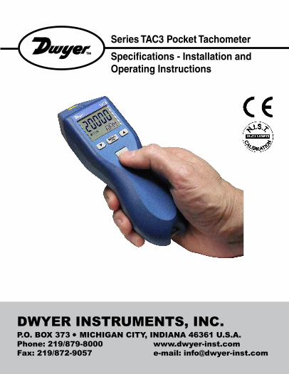
DWYER INSTRUMENTS, INC.P.O. BOX 373 • MICHIGAN CITY, INDIANA 46361 U.S.A.
Phone: 219/879-8000 www.dwyer-inst.com
Fax: 219/872-9057 e-mail: [email protected]
Series TAC3 Pocket Tachometer
Specifi cations - Installation and Operating Instructions

Diode LaserMax. output power: <1 milliwatt
Wavelength: 650 nanometers (visible light)
Min. divergence: 1.0 milliradian
Output: Continuous (CW)
Laser hazard classifi cation: Class 2
Contact info: www.dwyer-inst.com
Country of Origin: USA
SAFEGUARDS AND PRECAUTIONS
Laser hazards• Eye injury from beam - Do not look into the direct or refl ected beam; can cause eye injury
up to 25 ft (7.5 m) away.
• Visual interference (glare) with pilots and drivers - Interferes with vision up to 525 ft (160
m) away. Can be a distraction up to 1 mile (1.6 km) away. NEVER point any laser towards
aircraft or vehicles; it is unsafe and illegal.
Safe use guidanceClass 2 lasers are considered safe for
accidental eye exposure. Do not look or
stare into beam. Do not aim at aircraft.
This is not a toy. Always supervise children.
Read and follow all instructions in this manual carefully, and retain this manual for future reference.
Do not use this instrument in any manner inconsistent with these operating instructions or under any conditions that exceed the environmental specifi cations stated.
This instrument is not user serviceable. For technical assistance, contact the sales organization from which you purchased the product.
In order to comply with EU Directive 2012/19/EU on Waste Electrical and Electronic Equipment (WEEE): This product may contain material which could
be hazardous to human health and the environment. DO NOT DISPOSE of this
product as unsorted municipal waste. This product needs to be RECYCLED in
accordance with local regulations, contact your local authorities for more information. This
product may be returnable to your distributor for recycling - contact the distributor for details.

TABLE OF CONTENTSTABLE OF CONTENTS
1.0 OVERVIEW ..............................................................................12.0 FEATURE LOCATIONS ..........................................................13.0 LCD DISPLAY SYMBOLS.......................................................24.0 TAC3 SPECIFICATIONS .........................................................35.0 INPUT / OUTPUT ....................................................................76.0 PREPARATION FOR MEASUREMENT .................................8
6.1 Non-Contact Preparation ..............................................86.2 Direct Contact Preparation ...........................................86.3 Connecting External Sensors ......................................9
7.0 TAKING MEASUREMENTS ..................................................107.1 Non-Contact Measurements ......................................107.2 Direct Contact Measurements ...................................10
8.0 TACHometer Mode ...............................................................118.1 TACHometer Setup......................................................118.2 TACHometer Operation...............................................13
9.0 RATE Mode ...........................................................................139.1 RATE Setup ..................................................................149.2 RATE Operation ...........................................................16
10.0 TOTALizer Mode ...................................................................1710.1 TOTALizer Setup .........................................................1710.2 TOTALizer Operation ..................................................20
11.0 TIMER Mode .........................................................................2111.1 TIMER Setup ................................................................2111.2 TIMER Operation .........................................................22
12.0 BATTERIES ...........................................................................2313.0 CLEANING ............................................................................2414.0 OPTIONS /ACCESSORIES...................................................24

1
1.0 OVERVIEWThe Model TAC3 is a 32 function tachometer/ratemeter, totalizer/counter, and timer. It is programmable to read in English or Metric units. An input socket accepts remote sensing devices and an output socket allows for pulse output to external indicating devices. The Model TAC3 can be tripod mounted and “Locked-On” for accurate and continuous operation. This tachometer also stores minimum, maximum and last measurement in memory.
2.0 FEATURE LOCATIONS
Min / Scroll
Down arrow
Start / Reset button
Max / Scroll Up
arrow
LCD display
Menu / Select
and Lock-on
button
Battery compartment
AVOID EXPOSURE - LASER BEAM IS EMITTED FROM THIS APERTURE
Output socket
Input socket
Belt clip
Tripod mounting bushing
(underside)
2
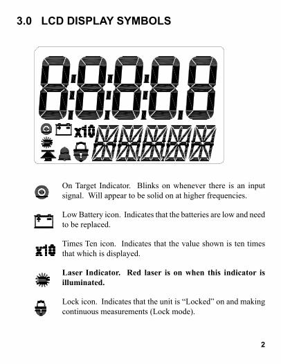
3.0 LCD DISPLAY SYMBOLS
On Target Indicator. Blinks on whenever there is an input signal. Will appear to be solid on at higher frequencies.
Low Battery icon. Indicates that the batteries are low and need to be replaced.
Times Ten icon. Indicates that the value shown is ten times that which is displayed.
Laser Indicator. Red laser is on when this indicator is
illuminated.
Lock icon. Indicates that the unit is “Locked” on and making continuous measurements (Lock mode).
3
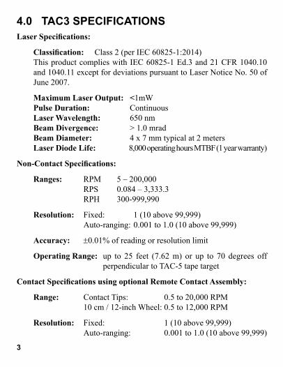
4.0 TAC3 SPECIFICATIONSLaser Specifi cations:
Classifi cation: Class 2 (per IEC 60825-1:2014)This product complies with IEC 60825-1 Ed.3 and 21 CFR 1040.10 and 1040.11 except for deviations pursuant to Laser Notice No. 50 of June 2007.
Maximum Laser Output: <1mW Pulse Duration: Continuous Laser Wavelength: 650 nm Beam Divergence: > 1.0 mrad Beam Diameter: 4 x 7 mm typical at 2 meters Laser Diode Life: 8,000 operating hours MTBF (1 year warranty)
Non-Contact Specifi cations:
Ranges: RPM 5 – 200,000 RPS 0.084 – 3,333.3 RPH 300-999,990
Resolution: Fixed: 1 (10 above 99,999) Auto-ranging: 0.001 to 1.0 (10 above 99,999)
Accuracy: ±0.01% of reading or resolution limit
Operating Range: up to 25 feet (7.62 m) or up to 70 degrees off perpendicular to TAC-5 tape target
Contact Specifi cations using optional Remote Contact Assembly:
Range: Contact Tips: 0.5 to 20,000 RPM 10 cm / 12-inch Wheel: 0.5 to 12,000 RPM
Resolution: Fixed: 1 (10 above 99,999) Auto-ranging: 0.001 to 1.0 (10 above 99,999)

Contact Specifi cations (continued):
Accuracy: Revs: ±0.05% of reading (RPM) or resolution limit (with no slippage)
Linear: ±0.5% of reading or resolution limit (with no slippage)
Contact Measurements Ranges:
TACHOMETER:
Revolutions per Minute (RPM) 0.5 to 20,000 RPM Revolutions per Second (RPS) 0.0833 to 333.33 RPS Revolution per Hour (RPH) 30 to 999,990 RPH
RATES: Wheel Circumference:
Inches per Second 10 cm: 0.033 to 1312.3 IPS 12 in: 0.100 to 2,400.0 IPS
Inches per Minute 10 cm: 1.969 to 78,740 IPM 12 in: 6.000 to 144,000 IPM
Inches per Hour 10 cm: 118.11 to 999,990 IPH 12 in: 360.00 to 999,990 IPH
Feet per Second 10 cm: 0.003 to 109.36 FT/S 12 in: 0.009 to 200.00 FT/S
Feet per Minute 10 cm: 0.164 to 6,561.7 FT/M 12 in: 0.500 to 12,000 FT/M
Feet per Hour 10 cm: 9.843 to 393,700 FT/H 12 in: 30.000 to 720,000 FT/H
Yards per Second 10 cm: 0.001 to 36.453 YPS 12 in: 0.003 to 66.667 YPS
Yards per Minute 10 cm: 0.055 to 2,187.2 YPM 12 in: 0.167 to 4,000.0 YPM
4

Contact Measurements Ranges (continued):
RATES: Wheel Circumference:
Yards per Hour 10cm: 3.281 to 131,233 YPH 12 in: 10.000 to 240,000 YPH
Miles per Hour 10 cm: 0.002 to 74.564 MPH 12 in: 0.006 to 136.36 MPH
Centimeters per Second 10 cm: 0.084 to 3,333.3 CM/S 12 in: 0.21 to 3,048.0 CM/S
Centimeters per Minute 10 cm: 5.000 to 200,000 CM/M 12 in: 15.240 to 365,760 CM/M
Centimeters per Hour 10 cm: 300.00 to 999,990 CM/H 12 in: 914.40 to 999,990 CM/H
Meters per Second 10 cm: 0.001 to 33.333 M/SEC 12 in: 0.003 to 60.960 M/SEC
Meters per Minute 10 cm: 0.050 to 2,000.0 M/MIN 12 in: 0.153 to 3,657.6 M/MIN
Meters per Hour 10 cm: 3.000 to 120,000 M/H 12 in: 9.144 to 219,460 M/H
TOTALIZER:
Counts: 0 to 999,999 Scale Totals in Inches, Feet, Yards, Centimeters or Meters Input: Internal or External optics or linear contact wheel
Timer Specifi cations:
Minutes:Seconds.Tenths to 99:59.9
Accuracy: ±0.2 second
Resolution: 0.1 second5

Display: Dual LCD Display (5-digit upper/scrolling, 5-digit alphanumeric lower display)
Batteries: 2 “AA” 1.5 V (DC) alkaline included (Note: Batteries are NOT rechargeable.)
Battery Life: 30 hours continuous typical with batteries provided
External Input:
Absolute max: -0.3 V to 5 V (DC)
Minimum: low below 1.2 V and high above 2 V (TTL compatible)
Edge: Triggers on Positive edge
Power Out: 3.0 V nominal, approx. 2.8 V @ 20 mA max
Pulse Output: 0 V to 3.3 V (DC) pulse Same shape as External Input signal or high when internal
optics sees a refl ection
Dimensions: 6.92” (17.58 cm) H x 2.4” (6.10 cm) W x 1.6” (4.06 cm) D
Weight: Approx. 7 oz. (210 g)
This product is designed to be safe for indoor use under the following conditions (per IEC61010-1).
Installation Category II per IEC 664
Pollution Degree Level II per IEC 664
Temperature: 40 °F to 105 °F (5 °C to 40 °C)
Humidity: Maximum relative humidity of 80% for temperatures up to 88 °F (31 °C) decreasing linearly to 50% relative humidity at 100 °F (40 °C). Humidity non-condensing.
Specifi cations subject to change without notice.6

7
5.0 INPUT / OUTPUT
Output socket (q)
Input socket (p)
Input: Accepts remote sensor or Remote Contact Assembly. 1/8” (3.5mm) stereo phone plug.
Output: 1 pulse per revolution TTL output on internal operation. Pulse repeater with external sensors. 1/8” (3.5mm) mono phone plug.
Pulse Output
Common
(GND)
Common
(GND)
Pulse Output
Signal Input
+3V Out to
Sensor
Common
(GND)
Common
(GND)
+3V Out to
Sensor
Signal Input
Input Connector Detail (Stereo plug)
Output Connector Detail (Mono plug)
8
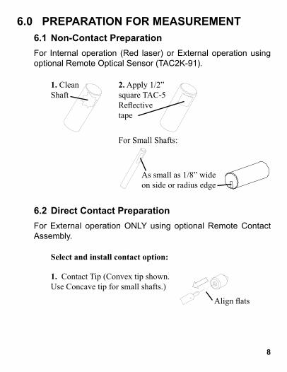
6.0 PREPARATION FOR MEASUREMENT
6.1 Non-Contact Preparation
For Internal operation (Red laser) or External operation using
optional Remote Optical Sensor (TAC2K-91).
6.2 Direct Contact Preparation
For External operation ONLY using optional Remote Contact
Assembly.
1. Clean Shaft
As small as 1/8” wide on side or radius edge
2. Apply 1/2” square TAC-5 Refl ective tape
For Small Shafts:
Select and install contact option:
1. Contact Tip (Convex tip shown. Use Concave tip for small shafts.)
Align fl ats

9
6.3 Connecting External Sensors
Tighten screw securely into fl at on shaft.
Install with pin in shaft fully seated in slot. Tighten screw.
2. 10 cm Wheel 3. 12 inch Wheel
OR
Plug sensor into Input socket
Remote Optical Sensor (TAC2K-91)
Remote Contact Assembly
(shown with optional 12 inch wheel)
�
Inp
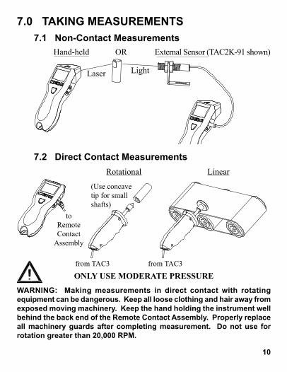
7.0 TAKING MEASUREMENTS
7.1 Non-Contact Measurements
7.2 Direct Contact Measurements
10
Hand-held
Laser
External Sensor (TAC2K-91 shown)OR
Light
WARNING: Making measurements in direct contact with rotating equipment can be dangerous. Keep all loose clothing and hair away from exposed moving machinery. Keep the hand holding the instrument well behind the back end of the Remote Contact Assembly. Properly replace all machinery guards after completing measurement. Do not use for rotation greater than 20,000 RPM.
to Remote Contact
Assembly
from TAC3 from TAC3
Rotational Linear
(Use concave tip for small shafts)
ONLY USE MODERATE PRESSURE

11
1. Turn Power ON
2. Enter Setup
3. Enter selection of Mode
4. Select TACH Mode
5. Save and advance
OR Repeat until TACH displayed
Last Mode selected is displayed
1a. To toggle Lock On/Off
Last Units selected are displayed
Locked OnPress and Hold
8.0 TACHometer ModeTachometer measures speed or linear rate with respect to time. Time intervals are sceonds, minutes, or hours. Rotational speed can be measured in Revolutions (Revs) per second, per minute, or per hour. The most common measurement is RPM or Revs per minute using the optical tachometer mode.
8.1 TACHometer Setup

12
NONE, 1, 2 or 3
OR Repeat until desired decimal places displayed
Unit will remember these settings (including lock on/off) even if turned off and back on.
OR Repeat until desired Units displayed
DONE, then Units selected
6. Enter selection of Units
7. Select Units
8. Save and advance
9. Enter selection of number of decimal places
10. Select decimal places
11. Save and advance
12. Exit Setup – Ready to
measure
RPS, RPM or RPH
13
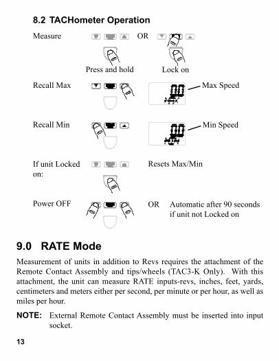
8.2 TACHometer Operation
Measure
Recall Max
Recall Min
If unit Locked on:
Power OFF
Min Speed
Max Speed
Automatic after 90 seconds if unit not Locked on
OR
Press and hold Lock on
Resets Max/Min
OR
9.0 RATE ModeMeasurement of units in addition to Revs requires the attachment of the Remote Contact Assembly and tips/wheels (TAC3-K Only). With this attachment, the unit can measure RATE inputs-revs, inches, feet, yards, centimeters and meters either per second, per minute or per hour, as well as miles per hour.
NOTE: External Remote Contact Assembly must be inserted into input socket.

14
9.1 RATE Setup
1. Turn Power ON
2. Enter Setup
3. Enter selection of Mode
4. Select RATE Mode
5. Save and advance
6. Enter selection of Units
OR Toggles between RATE and TOTAL. Select RATE.
Last Mode selected is displayed
1a. To toggle Lock On/Off
Rotational: C RPS,
C RPM or C RPH
EXTRN, then scrolling message, then last Units selected
Locked On
Linear: IPS, IPM, IPH, FT/S, FT/M, FT/H, YPS, YPM, YPH, MPH, CM/S, CM/M, CM/H, M/SEC, M/MIN, M/H
Press and Hold

15
NONE, 1, 2 or 3
OR Repeat until desired decimal places displayed
OR Repeat until desired Units displayed
8a. Enter selection of Wheel
8b. Select Wheel
8c. Save and Advance
Only for Linear Units:Rotational Units Linear Units
OR
OR Toggles between 10CM
and 12IN
Last Wheel selected is displayed
7. Select Units
8. Save and advance
9. Enter selection of number of decimal places
10. Select decimal places
11. Save and advance
RATE Setup (continued):
16
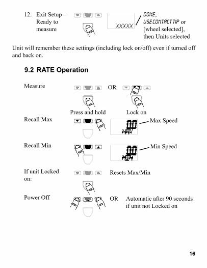
Unit will remember these settings (including lock on/off) even if turned off and back on.
DONE, USE CONTACT TIP or
[wheel selected],then Units selected
Min Speed
Max Speed
OR
Press and hold Lock on
12. Exit Setup – Ready to
measure
Measure
Recall Max
Recall Min
If unit Locked on:
Power Off
Resets Max/Min
9.2 RATE Operation
Automatic after 90 seconds if unit not Locked on
OR
17
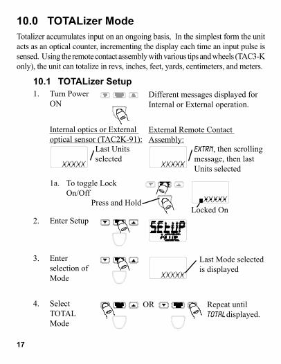
1. Turn Power ON
2. Enter Setup
3. Enter selection of Mode
4. Select TOTAL Mode
OR Repeat until TOTAL displayed.
Last Mode selected is displayed
1a. To toggle Lock On/Off
Different messages displayed for Internal or External operation.
Locked On
Internal optics or External optical sensor (TAC2K-91):
External Remote Contact Assembly:
EXTRN, then scrolling message, then last Units selected
Last Units selected
Press and Hold
10.0 TOTALizer ModeTotalizer accumulates input on an ongoing basis, In the simplest form the unit acts as an optical counter, incrementing the display each time an input pulse is sensed. Using the remote contact assembly with various tips and wheels (TAC3-K only), the unit can totalize in revs, inches, feet, yards, centimeters, and meters.
10.1 TOTALizer Setup

18
5. Save and advance
6. Enter selection of Units
7. Select Units
8. Save and advance
Rotational: REV
Linear: INCH, FEET, YARDS, CM, METER
Different options displayed for Internal or External operation.
Internal or External: External Remote Contact Assembly:COUNT Only
OR Repeat until desired Units displayed
COUNT or REV Linear Units
OR
8a. Enter selection of Wheel
8b. Select Wheel
8c. Save and Advance
Only for Linear Units:
OR Toggles between 10CM and 12IN
Last Wheel selected is displayed
19
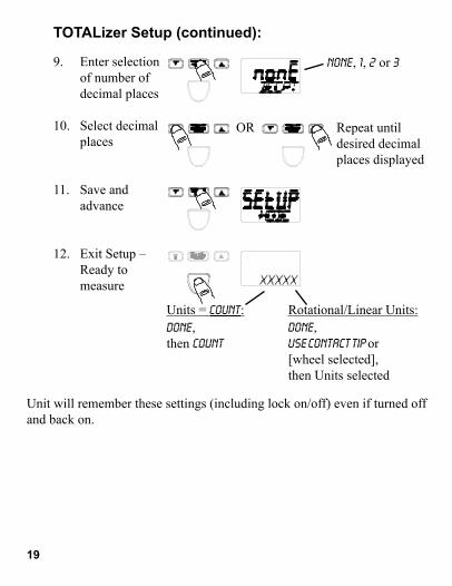
TOTALizer Setup (continued):
NONE, 1, 2 or 3
OR Repeat until desired decimal places displayed
Unit will remember these settings (including lock on/off) even if turned off and back on.
DONE, then COUNT
DONE, USE CONTACT TIP or
[wheel selected],then Units selected
Units = COUNT: Rotational/Linear Units:
9. Enter selection of number of decimal places
10. Select decimal places
11. Save and advance
12. Exit Setup – Ready to
measure

20
Measure
Recall Max or Min
Recall Time in seconds
If unit is Locked on:
Power Off
Shows time in seconds from when the Start / Reset button is pressed until the last input signal measured.
Max or Min Speed (in last selected Tach or Rate mode units)
OR
Press and hold Lock on
Resets Max/Min, Total and Measurement Time
10.2 TOTALizer Operation
Automatic after 90 seconds if unit not Locked on
OR
NOTE: Pressing once before 90 seconds will keep measurements in memory and the display turned on longer.
OR

21
1. Turn Power ON
2. Enter Setup Mode
3. Enter selection of Mode
4. Select TIMER Mode
5. Save and advance
OR Repeat until TIMER displayed
Last Mode selected is displayed
1a. To toggle Lock On/Off
Last Units selected are displayed
Locked OnPress and Hold
11.0 TIMER ModeAccumulates time in minutes, seconds, and tenths of a second. There are two modes of operation. The Manual mode operates like a stopwatch, the timing period being started and stopped by the user. The Auto mode can be stopped and started by the user or a piece of refl ective tape on objects. The user can freeze the display-and view/record a LAP time-at any time without affecting the count.
11.1 TIMER Setup
22
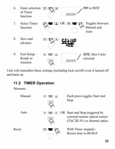
6. Enter selection of Timer function
7. Select Timer function
8. Save and advance
9. Exit Setup – Ready to
measure
Measure:
Reset
Unit will remember these settings (including lock on/off) even if turned off and back on.
DONE, then Units selected
Manual
Auto
Each press toggles Start and Stop
Start and Stop triggered by external remote optical sensor (TAC2K-91) or internal optics
With Timer stopped - Resets time to 00:00.0
OR
11.2 TIMER Operation
MAN or AUTO
OR Toggles between Manual and Auto

23
With Timer running - Stops at elapsed time to date.To continue, press again.
If Timer stopped - Automatic after 90 seconds (if unit not Locked on)
Automatic after 99:59.9
OR
When displayed, replace batteries.
Remove battery cover
Install two 1.5V “AA” alkaline batteries
NOTE: Both batteries face the same direction.
Lap
Power Off
OR
TIMER Operation (continued):
12.0 BATTERIES

13.0 CLEANINGTo clean the instrument, wipe with a damp cloth using mild soapy solution.
14.0 OPTIONS /ACCESSORIESTAC2K-91 Remote Optical Sensor, includes mounting bracket and 8
foot [2.5 m] cable
TAC-5 Refl ective Tape, 5 foot [1.5 m] roll, ½ inch [13 mm] wide
TAC3-1 Remote Contact Assembly, includes 6 foot [1.8 m] cable, convex and concave tips and 10 cm contact wheel
24

Printed in the U.S.A.
Copyright 2017, all rights reserved
1071-4838-6121071-4838-612E-0717