Embed Size (px)
Citation preview

Operation andMaintenance Manual
Series 909AR MiniatureIonization Gauge Transducer


Series 909AR MIGT
Part # 100014442
Series 909AR MiniatureIonization Gauge Transducer

Series 909AR MIGT
Part # K909AR - XX__________________
Please fill in the transducer part and flange typenumbers in the space above and have them readilyavailable when calling for service or additionalinformation.
(The part number can be found on your packing slip.Both the part number and serial number are located onthe bottom side of the housing.)
For more information or literature, contact:
Kurt J. Lesker Company1925 Route 51Clairton, PA 15025-3681 USA
Phone: 1- 412-387-92001-800-245-1656
Fax: 1-412-384-2745
©2006 by the Kurt J. Lesker Company, All rights reserved.

Series 909AR MIGT
Table of Contents
Package Contents ..................................................................... 7
Symbols Used in this Manual .................................................... 8
Safety Precautions .................................................................... 9
General Specifications ............................................................ 10
Feature and Control Locations ................................................ 11
About the 909AR MIGT ........................................................... 12
Typical Applications for the 909AR MIGT ................................ 13
Installing the 909AR MIGT ...................................................... 14Hot Cathode Sensor Installation .............................................................14
Location ...........................................................................................14Orientation .......................................................................................14Contamination ..................................................................................15
Vacuum Connection ...............................................................................15Electrical Connection .............................................................................16
Input/Output Wiring ..........................................................................16909AR MIGT Electrical Connections Table .......................................17
Relay Inductive Loads and Arc Suppression ..........................................17
Operation................................................................................. 18909AR MIGT Factory Defaults Table ......................................................18RS-485 Protocol .....................................................................................19
Standard Addresses ........................................................................19Universal Addresses ........................................................................19Query and Command Syntax ...........................................................19Response Syntax (ACK/NAK) .........................................................20
RS-485 Command Set ............................................................ 21Set Up and Status Commands ...............................................................21
Address – AD ..................................................................................21Baud Rate – BR ...............................................................................21Device Type – DT .............................................................................22Emission Current – EC ....................................................................22Factory Default – FD ........................................................................22Filament Status – FS .......................................................................22Firmware Version – FV .....................................................................22Gas Correction – GC........................................................................23Hardware Version – HV ....................................................................23Model – MD .....................................................................................23Serial Number – SN .........................................................................23

Series 909AR MIGT
Test RS485 – TST ............................................................................23Time On – TIM .................................................................................24Transducer Status – T ......................................................................24Transducer Temperature – TEM ........................................................24Unit – U ............................................................................................25User Tag – UT ..................................................................................25
Pressure Measurement and Degas Commands ......................................25Filament Power – FP........................................................................25Pressure Reading – PR1 ..................................................................25Degas Power – DG...........................................................................26
Set Point Commands .............................................................................26Set Point Value – SP1 ......................................................................26Hysteresis Value – SH1 ...................................................................26Enable Set Point – EN1 ...................................................................27Set Point Status – SS1 ....................................................................27Protect Set Point – PRO ..................................................................27
Degasing the Sensor ............................................................... 28
Sensitivities Relative to Nitrogen ............................................ 29Gas Correction Factor Table ...................................................................29
Analog Output ......................................................................... 30Analog Output Table ...............................................................................30
Bakeout/Sensor Replacement................................................. 32Bakeout ..................................................................................................32Sensor Replacement ..............................................................................33
Maintenance and Troubleshooting .......................................... 34Maintenance and Troubleshooting Table ..................................................34Sensor Test Resistance Values Table .....................................................35
Accessories and Part Replacement ........................................ 36
Notes ....................................................................................... 37
Appendix: Theory of a Hot Cathode Ionization Sensor ............ 38
Series 909AR MIGT 7
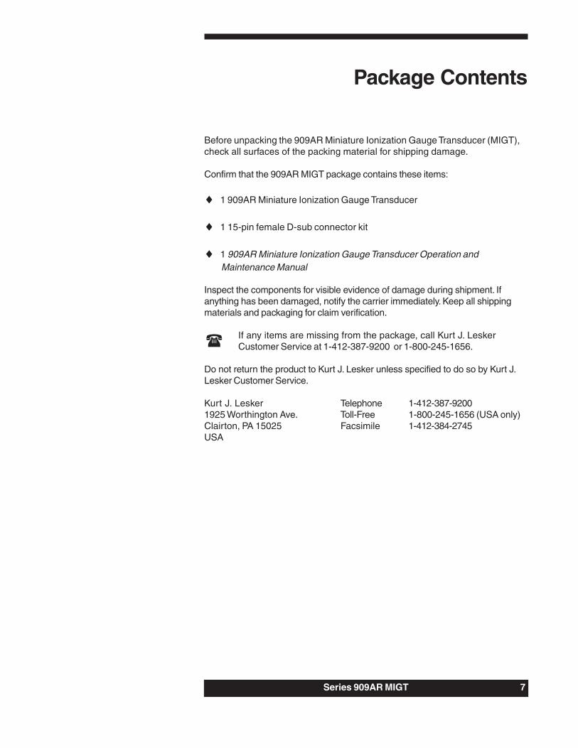
Before unpacking the 909AR Miniature Ionization Gauge Transducer (MIGT),check all surfaces of the packing material for shipping damage.
Confirm that the 909AR MIGT package contains these items:
♦ 1 909AR Miniature Ionization Gauge Transducer
♦ 1 15-pin female D-sub connector kit
♦ 1 909AR Miniature Ionization Gauge Transducer Operation andMaintenance Manual
Inspect the components for visible evidence of damage during shipment. Ifanything has been damaged, notify the carrier immediately. Keep all shippingmaterials and packaging for claim verification.
If any items are missing from the package, call Kurt J. LeskerCustomer Service at 1-412-387-9200 or 1-800-245-1656.
Do not return the product to Kurt J. Lesker unless specified to do so by Kurt J.Lesker Customer Service.
Kurt J. Lesker Telephone 1-412-387-92001925 Worthington Ave. Toll-Free 1-800-245-1656 (USA only)Clairton, PA 15025 Facsimile 1-412-384-2745USA
Package Contents

8 Series 909AR MIGT
CAUTION: Risk of electrical shock.
CAUTION: Refer to the manual. Failure to heed the message couldresult in personal injury, serious damage to the equipment, or both.
Calls attention to important procedures, practices, orconditions.
Symbols Used in this Manual

Series 909AR MIGT 9
Safety Precautions
Always disconnect the power supply before removingelectronics from the sensor for sensor replacement or bakeoutpurposes. Lethal voltages and currents may be present while thecircuit is operating. Only a qualified technician should replace oradjust electronic components.
Do not operate in explosive environments. The sensor has aheated element which could ignite a gas mixture used in the system.
Properly ground the transducer. The transducer should beconnected to earth ground both through the vacuum flange and theback shell of the electrical connector.
Use the proper power source. Use + 24 VDC @ 0.75 Amps.
Do not turn on filament power when system pressure is above5x10-2 Torr. Sensor damage will result.

10 Series 909AR MIGT
General Specifications
3x10⁻¹⁰ to 5x10⁻² Torr
5x10⁻¹⁰ to 9.0x10⁻³ Torr
0 to 10 VDC
Approximately ± 5% of reading
Nitrogen/Air
50 Milliseconds
3 Watts
3x10⁻¹⁰ Torr
2
Y2O3 coated iridium
24 ± 2 VDC
0.75 Amps
1A @ 30 VAC/VDC
304 stainless steel, glass, tungsten, platinumclad molybdenum, yttria coated iridium
0 to 40oC
150oC with KF and Viton® seal; 300oC with CFand copper seal
Any
EN-61326-1, EN-61010-1
Mini CF, 2.75” CF, NW16 KF, NW25 KF,NW40 KF
2.9” x 3.1” x 4.0” (74 x 79 x 102 mm)
0.70 lbs. (.32 kg)
Measuring range
Set point range
Analog out
Repeatability
Calibration gas
Response time
Degas power
X-ray limit
Number of filaments
Filament type
Supply voltage
Supply current (max)
Relay contact rating
Materials exposed tovacuum
Operatingtemperature
Bakeout temperature(electronics removed)
Installation orientation
CE certification
Vacuum connections
Dimensions (1” ODtube)
Weight (1” OD tube)
Series 909AR MIGT 11
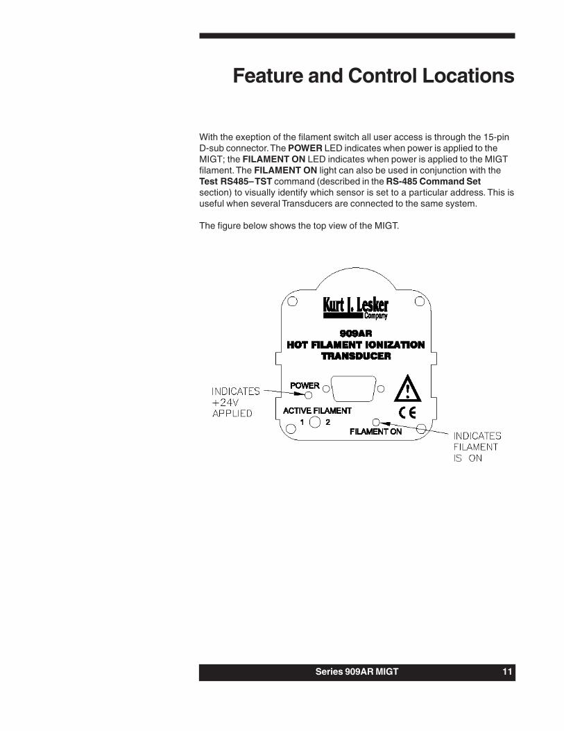
With the exeption of the filament switch all user access is through the 15-pinD-sub connector. The POWER LED indicates when power is applied to theMIGT; the FILAMENT ON LED indicates when power is applied to the MIGTfilament. The FILAMENT ON light can also be used in conjunction with theTest RS485– TST command (described in the RS-485 Command Setsection) to visually identify which sensor is set to a particular address. This isuseful when several Transducers are connected to the same system.
The figure below shows the top view of the MIGT.
Feature and Control Locations

12 Series 909AR MIGT
The 909AR MIGT measures vacuum chamber pressures as part of a user’sdefined system processes. Once integrated into the vacuum system, theMIGT’s functions can be controlled by a serial interface, logic lines or relayfrom a p/c, or manual switches.
This manual describes the installation and configuration tasks necessary toset up the 909AR MIGT.
For additional information on how the MIGT works, see the appendix Theoryof a Hot Cathode Ionization Sensor.
About the 909AR MIGT

Series 909AR MIGT 13
Typical Applications for the909AR MIGT
♦ Measure high vacuum chamber pressure.
♦ Control system pressure using digital communications or analog outputas input to an automatic pressure controller.
♦ Measure pressure of backfilled gases.
♦ Sense abnormal pressure and take appropriate security measures usingrelay set points.
♦ Start or stop system processes with relay set points.

14 Series 909AR MIGT
Hot Cathode Sensor Installation
Location
Locate the 909AR MIGT where it can measure chamber pressure. Install thedevice away from pumps and gas sources so it will give the mostrepresentative pressure values. If the sensor is going to be baked out, thefour screws on the panel closest to the flange will need to be removed (seethe Bakeout section for details). Locate the sensor to ensure easy access tothose four screws.
ENSURE EASY ACCESS TOREMOVE FOR BAKEOUT
Orientation
The MIGT can be installed and operated in any position withoutcompromising accuracy.
Installing the 909AR MIGT

Series 909AR MIGT 15
Contamination
Locate and orient the MIGT where contamination is least likely. For example,if the MIGT is mounted directly above a source of evaporation, the vaporcould contaminate the sensor elements and cause the calibration to shift.Whenever possible, install the MIGT with the vacuum port facing down tokeep particulates or liquids from entering the device. To prevent inaccuratepressure measurements, shield an MIGT located near an electron or ionsource (e.g., near an electron beam source or in a sputtering system) andmount it away from strong magnetic fields.
Vacuum Connection
The MIGT is available with the following flanges:
♦ 2.75” CF (rotatable)
♦ 1.33” CF (rotatable)
♦ KF 16
♦ KF 25
♦ KF 40
The figure below shows the dimensions for each flange type. The topdimensions, also shown below, are valid for any flange configuration.

16 Series 909AR MIGT
An 909AR MIGT with a KF flange and/or elastomer O-ring is suitable only forpressure measurement down to 10-7 Torr. Use Viton or silicone seals; Bunaseals are not recommended for use with any hot cathode sensor or 909ARMIGT. Use only metal clamps on MIGTs with KF flanges to ensure a goodelectrical connection from the sensor body to the vacuum chamber.Additionally, the vacuum chamber must be grounded.
Electrical Connection
Use a cable with a mating 15-pin D-sub connector with strain reliefs to ensureproper electrical connection and to reduce stress on the connectors.
Ensure a low impedance electrical connection between the MIGTsensor body and the grounded vacuum system to shield thesensor from external electromagnetic sources (see previoussection on Vacuum Connection).
Input/Output Wiring
The figure and the 909AR MIGT Electrical Connections Table on thefollowing page identify the pins of the MIGT connector and their functions;make a cable using this information. To comply with EN61326-1 immunityrequirements, use a braided, shielded cable. Connect the braid to the metalhoods at both ends of the cable with the end for power supply connected toearth ground. The connector kit shipped with the MIGT includes a metal shell,which provides an easy and effective means of connecting the braid to it.
The power supply input is 24 VDC. The positive side of the power supply isconnected to pin 3 and the negative side to pin 4 of the male D-subconnector.
Damage may occur to the circuitry if excessive voltage is applied,polarity reversed, or if a wrong connection is made.
If using analog output (described in the Analog Output section), the analogoutput voltages are pins 5 (+) and 6 (-). Connect them to a differential inputvoltmeter or an analog-to-digital (A/D) converter with a differential input in asystem controller.
Do not connect the negative side of the analog output (pin 6) tothe negative side of the power supply input (pin 4) or to anyother ground. Doing so will cause half of the power current toflow through this wire. Measurement errors in the output voltagemay be seen due to the voltage drop from this current. Thelonger the cable, the worse the error will be.
Do not connect the set point relay terminals to the analog output.

Series 909AR MIGT 17
15 Pin 909AR Pinout
Relay Inductive Loads and Arc SuppressionIf using the set point relay to switch inductive loads (e.g., solenoids, relays,transformers, etc.), the arcing of the relay contacts might interfere with MIGToperation and reduce relay contact life. Therefore, an arc suppressionnetwork, shown schematically below, is recommended.
The values of the capacitance C and the resistance R can be calculated bythe following equations:
C = I2/(1 x 107)
R = E/ Ia
where:C is in faradsR is in ohmsI is DC or Acpeak load current in amperesE is DC or Acpeak source voltage in voltsa = 1 + (50/ E)Note that Rmin = 0.5 Ω and Cmin = 1.0 x 10⁻⁹ F
rebmuNniP noitcnuF stnemmoC1 -584SR2 +584SR3 42+4 dnuorGrewoP5 +tuOgolanA6 -tuOgolanA7 CN8 ONyaleR9 nommoCyaleR01 CNyaleR
11 ffo/noegauG )egaugselbanednuorgro0cigol(wolevitcAFFO=CN
21 ffo/nosageD )sagedselbanednuorgro0cigol(wolevitcAFFO=CN
31 egnaRnoissimE .egnarotuaselbanednuorgro0cigoLAm1.0=CN
41 sutatSsageD sagednehwdnuorgotdetcennoc-rotcelloCnepOffosi
51 sutatSegauG egaugnehwdnuorgotdetcennoc-rotcelloCnepOffosi

18 Series 909AR MIGT
OperationMANUAL OPERATIONSERIAL COMMUNICATIONS OPERATION
CAUTION: Never turn on filament power when the system pressure isabove 5x10⁻² Torr! Sensor damage will result!
The 909AR MIGT operation parameters are preset at the factory. The tablebelow shows the factory default settings. Use the user interface and thecommands described on the following pages to change parameter settingsas necessary. The user interface to the MIGT is through RS-485 serialcommunications. RS485+ is pin 2 and RS485- is pin 1.
909AR MIGT Factory Defaults Table
gnitteS tluafeD
sserddA 352
duaB 0069
tinU rroT
rewoPtnemaliF ffO
rewoPsageD ffO
noitcerroCsaG 1
1tnioPteS rroT01-E0.5
1siseretsyH )rroT01-E5.5(%01+
tnioPteSelbanE ffO
erusserPtnioPteStcetorP rroT2-E0.5
tnerruCnoissimE otuA

Series 909AR MIGT 19
Maunal Operation
Gauge On/Off
The gauge is turned on by connecting Gauge on/off (pin 11) to power ground.
Do not turn on the gauge if the pressure is above 5 x10⁻² Torr. Filament damage may resuslt.
Use the analog output to measure pressure (refer to Analog Output section).
When the gauge is off, the gauge status line (pin 15) is connected to powerground through an electronic switch. The gauge status is disconnected or“open collector” when the gauge is on. See Figure 1.
The gauge can turn itself off in one of three ways:
1. Pressure exceeds 5 x 10⁻² Torr2. The circuitry detects low or no emission current (pressure too high or filament burnt out).3. Active filament has been changed.
In any of these cases the Gauge On/Off must be disconnected andreconnected to system ground to turn the gauge back on.
Emission Current
In the emission current pin (pin 13) is connected to power ground the gaugewill perform an emission current range change as follows:
Decreasing pressure: switches to 1mA at 8.0 x 10⁻⁵ TorrIncreasing pressure: switches to 0.1mA at 1.0 x 10⁻⁴ Torr
If the emission current pin is left disconnected the emission current willalways be 0.1mA.
Degas
The degas mode is enabled when the degas pin (pin 12) is connected topower ground. Refer to the degas section for more information.
When degas is off the degas status pin (pin 14) is connected to powerground through an electronic switch. The degas status is disconnected or“open collector” when the degas is on. See figure 1.
20 Series 909AR MIGT
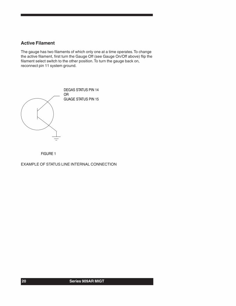
Active Filament
The gauge has two filaments of which only one at a time operates. To changethe active filament, first turn the Gauge Off (see Gauge On/Off above) flip thefilament select switch to the other position. To turn the gauge back on,reconnect pin 11 system ground.
DEGAS STATUS PIN 14ORGUAGE STATUS PIN 15
FIGURE 1
EXAMPLE OF STATUS LINE INTERNAL CONNECTION

Series 909AR MIGT 21
RS-485/232 Protocol
The MIGT supports 2400, 4800, 9600, and 19200 baud rates (factorydefault: 9600). The data format is 8 data bits, no parity, and one stop bit.
Standard Addresses
Valid addresses are 1 to 253 (factory default: 253).
Universal Addresses
The MIGT receives and responds to commands sent to address 254. Forexample, use 254 to communicate with a device if its address is unknown.The MIGT receives and acts upon commands sent to address 255, but doesnot respond; use 255 to broadcast messages to multiple devices attached tothe same system. For example, use 255 to turn on the filaments for allMIGTs connected to the same system.
Query and Command Syntax
Queries return current parameter settings; commands change the parametersetting according to the value the user types in the command syntax. Eachquery or command must begin with the attention character @ and end withthe termination string ;FF.
Syntax required for a query is:@<device address><query>?;FF.
Syntax required for a command is:@<device address><command>!<parameter>;FF.
Examples:
Query current baud rate: @253BR?;FFChange baud rate to 19200: @253BR!19200;FF
where:@ <attention character>253 <device address>BR? <query> (for query syntax)BR!19200 <command>!<parameter> (for command syntax);FF <terminator>

22 Series 909AR MIGT
Response Syntax (ACK/NAK)
The ASCII characters 'ACK' or 'NAK' preface the query or command responsestring. The ACK sequence signifies the message was processedsuccessfully. The NAK sequence indicates there was an error.
The response to a query or a successful command is:@<device address>ACK<data>;FF
The response to a message with an error is:@<device address>NAK<NAK code>;FF
Examples:
ACK response: @253ACK9600;FF (baud rate changed to 9600)NAK response: @253NAK160;FF (command had an error—possibly
a typo)
The following list provides descriptions of the NAK codes that may bereturned.
Error NAK CodeUnrecognized message 160Invalid argument 169Value out of range 172Command/query character invalid (! or ?) 175Write to nonvolatile memory failed 196Read from nonvolatile memory failed 197Not in measure pressure mode 198Pressure too high for degas 199

Series 909AR MIGT 23
RS-485/232 Command Set
The query and command formats shown in this section are examples; thevalues may vary for the user’s installation.
Set Up and Status Commands
Address – AD
The AD command returns or sets the MIGT address. Note: If multiple devicesare installed on the system, an address query using 254 (shown in the queryexample below) cannot determine the address of only one of the devices.
Values: 001 to 253 (default: 253)
Query: @254AD?;FFQuery Response: @254ACK001;FFCommand: @001AD!002;FFCommand Response: @002ACK002;FF
Baud Rate – BR
The BR command returns or sets the baud rate of the communicationsprotocol. The MIGT responds to this command at the present baud rate;however, the user will need to change the baud rate on the host to ensurefuture commands are sent at the same rate.
Values: 2400, 4800, 9600, 19200 (default: 9600)
Query: @001BR?;FFQuery Response: @001ACK9600;FFCommand: @001BR!19200;FFCommand Response: @001ACK19200;FF
Device Type – DT
The DT command returns the transducer device type.Query: @001DT?;FFQuery Response: @001ACKHCIG;FF (hot cathode ionization gauge)
Emission Current – EC
The EC command returns or sets the sensor’s emission current to 100uA orAuto range (100uA above 1x10⁻⁴ and 1mA below 1x10⁻⁴ Torr).

24 Series 909AR MIGT
Values: 100UA and AUTO for commands;100UA, 1MA AUTO, and 100UA AUTO for responses(default: AUTO).
Query: @001EC?;FFQuery Response: @001ACK1MA AUTO;FFCommand: @001EC!AUTO;FFCommand Response: @001ACK100UA AUTO;FF
Factory Default – FD
The FD command sets all MIGT parameter values to the factory defaultsettings shown in the 909 MIGT Factory Defaults Table (page 18). Note: TheFD command overrides all parameter values the user sets; use with caution!
Command: @001FD!;FFCommand Response: @001ACKFD;FF
Filament Status – FS
The FS command returns the operating status of the active filament. To selectbetween the sensor’s two filaments, see Active Filament – AF (this section).To turn the filament ON or OFF, see Filament Power – FP (PressureMeasurement and Degas Commands section).
Values: ON, OFF, HIGH (filament power is too high)
Query: @001FS?;FFQuery Response: @001ACKON;FF
Firmware Version – FV
The FV command returns the MIGT firmware version.
Query: @001FV?;FFQuery Response: @001ACK1.00;FF
Gas Correction – GC
The GC command returns or sets the gauge’s sensitivity for use with gassesother than air or nitrogen. For example, if Argon is the system gas then thegas correction value would be 1.29. See the Gas Correction Factor Table forvalues.
Values: 0.10 to 50.1 (default: 1)
Query: @001GC?;FFQuery Response: @001ACK1.00;FFCommand: @001GC!1.50;FFCommand Response: @001ACK1.50;FF
Series 909AR MIGT 25
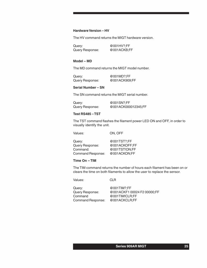
Hardware Version – HV
The HV command returns the MIGT hardware version.
Query: @001HV?;FFQuery Response: @001ACKB;FF
Model – MD
The MD command returns the MIGT model number.
Query: @001MD?;FFQuery Response: @001ACK909;FF
Serial Number – SN
The SN command returns the MIGT serial number.
Query: @001SN?;FFQuery Response: @001ACK000012345;FF
Test RS485 – TST
The TST command flashes the filament power LED ON and OFF, in order tovisually identify the unit.
Values: ON, OFF
Query: @001TST?;FFQuery Response: @001ACKOFF;FFCommand: @001TST!ON;FFCommand Response: @001ACKON;FF
Time On – TIM
The TIM command returns the number of hours each filament has been on orclears the time on both filaments to allow the user to replace the sensor.
Values: CLR
Query: @001TIM?;FFQuery Response: @001ACKF1 00024 F2 00000;FFCommand @001TIM!CLR;FFCommand Response: @001ACKCLR;FF

26 Series 909AR MIGT
Transducer Status – T
The T command returns the current status of the MIGT. Related commands:Active Filament – AF (this section); Set Point Value – SP1 and HysteresisValue – SH1 (Set Point Commands section).
Values: A = Set point 1 value out of boundsD = Degas fault, pressure too high to activate degasF = Filament fault, filament cannot turn onG = Gauge onO = OK, no errors to reportP = Pressure fault, system pressure above protect
pressure
Query: @001T?;FFQuery Response: @001ACKO;FF
Transducer Temperature – TEM
The TEM command returns the transducer’s on-chip Microprocessortemperature in oC. If the temperature exceeds 70oC, the ambient temperaturemay be too high or the filament power is too high (nominal temperature rise is30oC above ambient). See the Filament Status – FS or Transducer Status –T commands (this section) for how to query the filament power level. See theMaintenance and Troubleshooting section for more information ontroubleshooting temperature problems.
Query: @001TEM?;FFQuery Response: @001ACK32.0;FF

Series 909AR MIGT 27
Unit – U
The U command returns or sets the pressure unit to Torr, mBar, or Pascal. Theunits affect all pressure measurements, including set point values.
Values: TORR, MBAR, PASCAL (default: TORR)
Query: @001U?;FFQuery Response: @001ACKTORR;FFCommand: @001U!MBAR;FFCommand Response: @001ACKMBAR;FF
User Tag – UT
The UT command returns or sets the user tag label to assign for MIGTidentification.
Values: Up to 30 ASCII characters
Query: @001UT?;FFQuery Response: @001ACKCHAMBER1;FFCommand: @001UT!CHAMBER2;FFCommand Response: @001ACKCHAMBER2;FF
Pressure Measurement and Degas Commands
Filament Power – FP
CAUTION: Never turn on filament power when system pressure isabove 5x10⁻² Torr! Sensor damage will result!
The FP command turns the filament either ON or OFF. To query the ON/OFFstatus of the filament, use the Filament Status – FS command, or theTransducer Status – T command with the G value (Set Up and StatusCommands section).
Values: ON, OFF
Command: @001FP!ON;FFCommand Response: @001ACKON;FF
Pressure Reading – PR1
The PR1 command returns the measured pressure in scientific notation.
Query: @001PR1?;FFQuery Response: @001ACK6.3E-7;FF

28 Series 909AR MIGT
Degas Power – DG
Read the Degasing the Sensor section of this manual beforeusing the DG command.
The DG command turns degas ON or OFF, or indicates if the MIGT is indegas mode. Degas turns off automatically after 30 minutes, but can beturned off sooner.
Values: ON, OFF (default: OFF)
Query: @001DG?;FFQuery Response: @001ACKOFF;FFCommand: @001DG!ON;FFCommand Response: @001ACKON;FF
Set Point Commands
Set Point Value – SP1
The SP1 command returns or sets the set point value. The set point value isthe pressure below which the set point relay will be energized (i.e., N.O. and Ccontacts will be closed). The set point must be enabled for the SP1 commandto function (see the Enable Set Point – EN1 command, next page) .
Values: Two-digit number in scientific notation from 5.0E-10to 9.0E-3 Torr (default: 5.0E-10 Torr)
Query: @001SP1?;FFQuery Response: @001ACK1.0E-6;FFCommand: @001SP1!2.5E-7;FFCommand Response: @001ACK2.5E-7;FF
Hysteresis Value – SH1
The SH1 command returns or sets the pressure value above which the setpoint relay will be de-energized (i.e., N.C. and C contacts will be closed). Thehysteresis value must always be above the set point value (see the Set PointValue – SP1 command, above). If the hysteresis and set point are the samevalue, or nearly the same value, the relay may chatter when the systempressure is near the set point.
Values: Two-digit number in scientific notation from 5.0E-10to 9.0E-3 Torr (default: +10% (5.0E-10 Torr))
Query: @001SH1?;FFQuery Response: @001ACK2.8E-7;FFCommand: @001SH1!1.0E-7;FFCommand Response: @001ACK1.0E-7;FF
Series 909AR MIGT 29
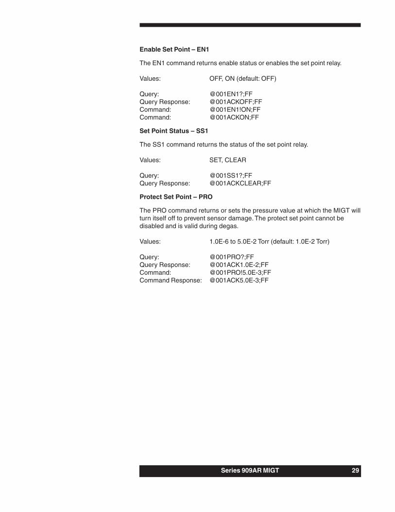
Enable Set Point – EN1
The EN1 command returns enable status or enables the set point relay.
Values: OFF, ON (default: OFF)
Query: @001EN1?;FFQuery Response: @001ACKOFF;FFCommand: @001EN1!ON;FFCommand: @001ACKON;FF
Set Point Status – SS1
The SS1 command returns the status of the set point relay.
Values: SET, CLEAR
Query: @001SS1?;FFQuery Response: @001ACKCLEAR;FF
Protect Set Point – PRO
The PRO command returns or sets the pressure value at which the MIGT willturn itself off to prevent sensor damage. The protect set point cannot bedisabled and is valid during degas.
Values: 1.0E-6 to 5.0E-2 Torr (default: 1.0E-2 Torr)
Query: @001PRO?;FFQuery Response: @001ACK1.0E-2;FFCommand: @001PRO!5.0E-3;FFCommand Response: @001ACK5.0E-3;FF

30 Series 909AR MIGT
Degasing the Sensor
Sensitivity of the sensor may drift if the sensor elements becomecontaminated with system process gasses. This becomes more of a problemthe lower the pressure being measured (i.e., (≤10-8 Torr). To rid the sensorelements of the excess system process gasses, periodically degas thesensor. How frequently to run degas varies for each system installation.
The 909AR MIGT uses Electron Bombardment (EB) degas to removeadsorbed gas from the sensor. Pressure can still be measured during degas,but due to the gas rapidly coming off the sensor elements, sensor pressuremay be significantly higher than system pressure.
Degas is only activated if the indicated pressure is below 1x10⁻⁵
Torr.
Set points are active during degas.
When degas is turned on, it is likely that the sensor pressure will increase tovalues exceeding 1x10⁻⁴ Torr. When the indicated pressure exceeds 1x10⁻⁴
Torr, degas turns off. Degas automatically turns on again when the indicatedpressure drops back below 1x10⁻⁴ Torr (patent# 6756785).
Expect the filament power status to be HIGH during degas.
The temperature inside the MIGT increases during degas; for electroniccomponent life, keep degas time as short as possible. Degas operationautomatically terminates after 30 minutes. When the sensor’s indicatedpressure has dropped back near pre-degas values, there is not much benefitto further degas operation; therefore, degas should be terminated.
Do not operate in degas mode more than 30 minutes every 4hours.
Series 909AR MIGT 31
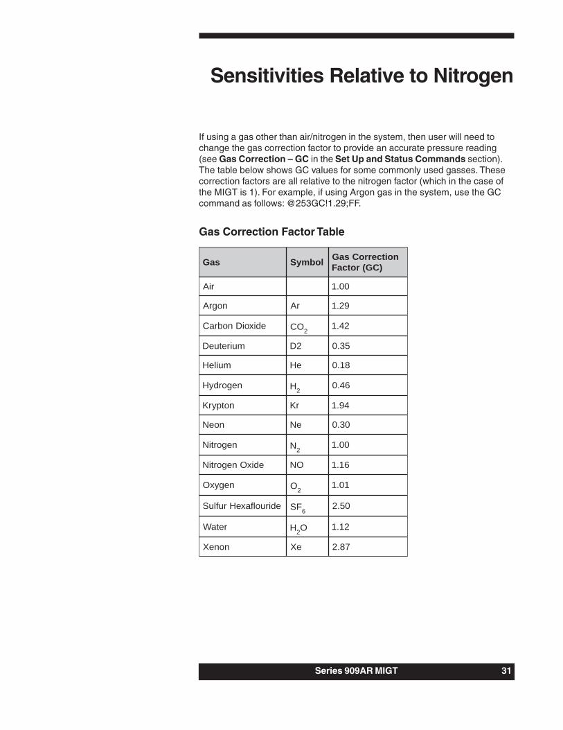
If using a gas other than air/nitrogen in the system, then user will need tochange the gas correction factor to provide an accurate pressure reading(see Gas Correction – GC in the Set Up and Status Commands section).The table below shows GC values for some commonly used gasses. Thesecorrection factors are all relative to the nitrogen factor (which in the case ofthe MIGT is 1). For example, if using Argon gas in the system, use the GCcommand as follows: @253GC!1.29;FF.
Gas Correction Factor Table
saG lobmyS noitcerroCsaG)CG(rotcaF
riA 00.1
nogrA rA 92.1
edixoiDnobraC OC 224.1
muiretueD 2D 53.0
muileH eH 81.0
negordyH H264.0
notpyrK rK 49.1
noeN eN 03.0
negortiN N200.1
edixOnegortiN ON 61.1
negyxO O210.1
ediruolfaxeHrufluS FS 605.2
retaW H2O 21.1
noneX eX 78.2
Sensitivities Relative to Nitrogen

32 Series 909AR MIGT
Analog Output
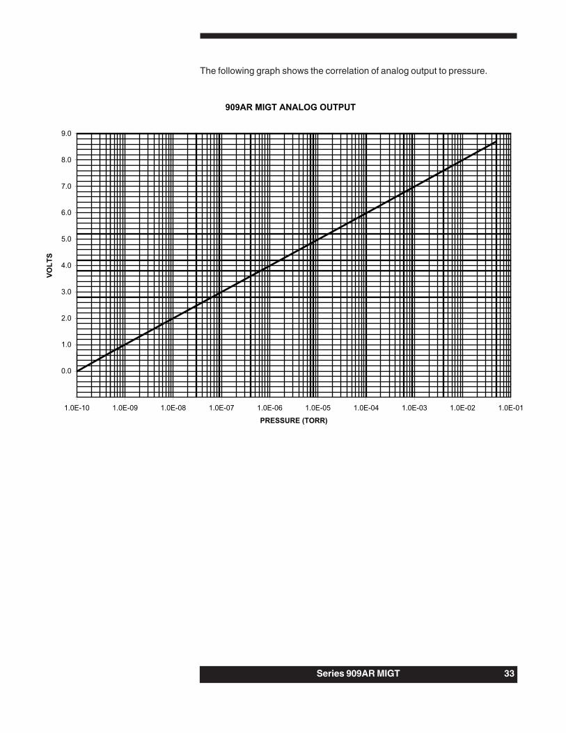
Analog output is an optional method of measuring pressure. The analogvoltage signal are pins 5 (+) and 6 (-). Connect them to a differential inputvoltmeter or ADC. The output is logarithmic, spanning 0-10V. The pressure/voltage relationship is P (Torr) = 10(Vo-10).
Analog Output: Pressure = 10(Vo-10) Torr
Do not connect the negative side of the analog output (pin 8) tothe power supply return (pin 4) or to any other ground. Thevoltage drop from the supply current will produce errors in theanalog output voltage. The longer the cable, the worse the errorwill be.
Analog Output Table
egatloV erusserP
stloV01 ffositnemaliF
stloV7.8 01x5 2- rroT
stloV0.8 01x1 2- rroT
stloV0.7 01x1 3- rroT
stloV0.6 01x1 4- rroT
stloV0.5 01x1 5- rroT
stloV0.4 01x1 6- rroT
stloV0.3 01x1 -7 rroT
stloV0.2 01x1 8- rroT
stloV0.1 01x1 9- rroT
stloV0.0 01x1 01- rroT
stloV0 recudsnartehtotdeilpparewopoN
Series 909AR MIGT 33
The following graph shows the correlation of analog output to pressure.

34 Series 909AR MIGT
Bakeout/Sensor Replacement
CAUTION: Disconnect the power supply before disassembly!Lethal voltages and currents may be present while the circuit isoperating. Only a qualified technician should replace or adjustelectronic components.
Bakeout
If building the system for the first time, or after performing routinemaintenance, the system may need to be baked out to remove any watervapor.
The sensor can be baked out to 300oC with a metal seal flange (CF) and150oC with a Viton® seal flange (KF). To bake out the sensor, first removethe electronics. To do this:
1. Disconnect the cable from the 909AR MIGT.2. Remove the four screws (as shown in the figure below). The screws may
be difficult to access when the sensor is attached to the vacuum system.3. Pull the metal housing and the electronics from the sensor. The bottom
panel remains attached to the sensor.

Series 909AR MIGT 35
Avoid removing the other four screws, two jack screws, top panel, andelectronics that leave the housing attached to the sensor. The housing haslabels that may come off, discolor, or burn at temperatures above 60oC, andthe housing will discolor at temperatures above 200oC.
To re-assemble the electronics, use the disassembly steps in reverse order.
Sensor Replacement
Before disassembling the electronics for sensor replacement, use the TimeOn – TIM command (described in the Set Up and Status Commandssection) to clear the filament time.
To disassemble the electronics for sensor replacement, use the procedure inthe Bakeout section.
To re-assemble the electronics, use the disassembly steps in reverse order.
For sensor part numbers, see the Accessories and Part Replacementsection.
36 Series 909AR MIGT
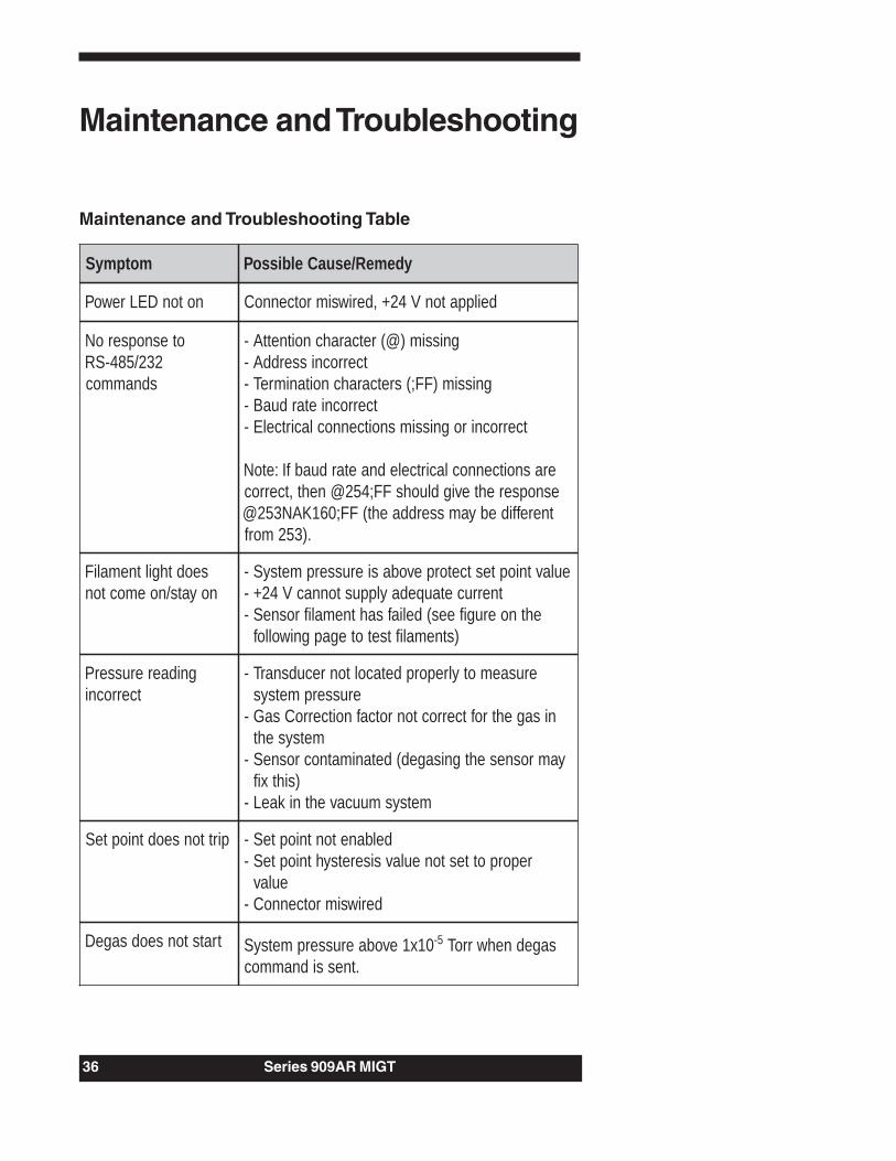
Maintenance and Troubleshooting
Maintenance and Troubleshooting Table
motpmyS ydemeR/esuaCelbissoP
notonDELrewoP deilppatonV42+,deriwsimrotcennoC
otesnopseroN232/584-SR
sdnammoc
gnissim)@(retcarahcnoitnettA-tcerrocnisserddA-
gnissim)FF;(sretcarahcnoitanimreT-tcerrocnietarduaB-
tcerrocnirognissimsnoitcennoclacirtcelE-
erasnoitcennoclacirtcelednaetarduabfI:etoNesnopserehtevigdluohsFF;452@neht,tcerroctnereffidebyamsserddaeht(FF;061KAN352@
.)352morf
seodthgiltnemaliFnoyats/noemocton
eulavtnioptestcetorpevobasierusserpmetsyS-tnerrucetauqedaylppustonnacV42+-
ehtnoerugifees(deliafsahtnemalifrosneS-)stnemaliftsetotegapgniwollof
gnidaererusserPtcerrocni
erusaemotylreporpdetacoltonrecudsnarT-erusserpmetsys
nisagehtroftcerroctonrotcafnoitcerroCsaG-metsyseht
yamrosnesehtgnisaged(detanimatnocrosneS-)sihtxif
metsysmuucavehtnikaeL-
pirttonseodtniopteS delbanetontniopteS-reporpottestoneulavsiseretsyhtniopteS-
eulavderiwsimrotcennoC-
tratstonseodsageD 01x1evobaerusserpmetsyS 5- sagednehwrroT.tnessidnammoc
Series 909AR MIGT 37
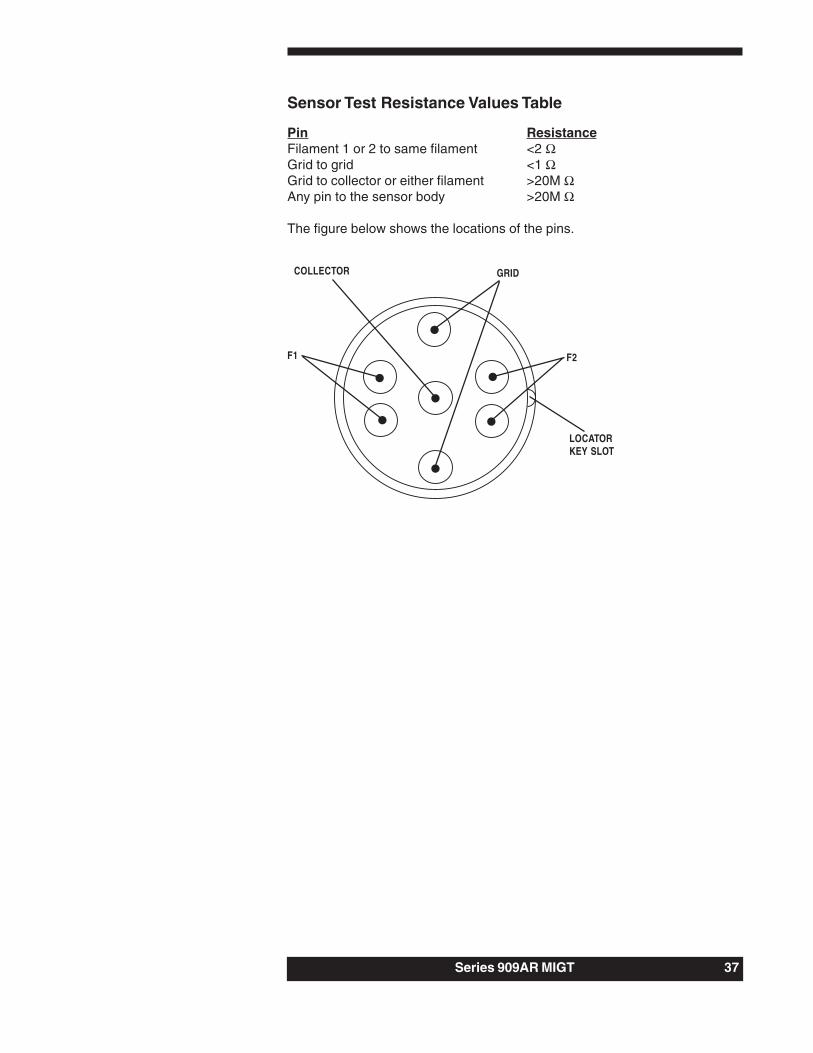
Sensor Test Resistance Values Table
Pin ResistanceFilament 1 or 2 to same filament <2 ΩGrid to grid <1 ΩGrid to collector or either filament >20M ΩAny pin to the sensor body >20M Ω
The figure below shows the locations of the pins.
GRID
F1
COLLECTOR
LOCATORKEY SLOT
F2

38 Series 909AR MIGT
Accessories and PartReplacement
Description Part NumberSensor with 2.75” CF 100011508Sensor with 1.33” CF 100011600Sensor with NW40 KF 100011602Sensor with NW25 KF 100011601Sensor with NW16 KF 100011603Sensor with 1” tube 100011820Connector Kit (female 15-pin D-sub) 100008104Operation and Maintenance Manual 100011798

Series 909AR MIGT 37
Notes:

38 Series 909AR MIGT
Appendix: Theory of a HotCathode Ionization Sensor
Hot cathode ionization sensors use thermionic electrons—electrons emittedfrom a hot filament (emission current)—to create ions in a defined volume. Intheir passage from the cathode through the gas volume, the electrons collidewith gas atoms or molecules to form ions. The number of gas moleculesionized depends on the energy of the ionizing electrons, typically about 150eV, and the ionization probabilities of the constituent gases. The total amountof ionization is related to the molecular concentration. The ions areaccelerated to a collector electrode, where they create a current (collectorcurrent) in a circuit, which includes an electrometer. The measured current isproportional to the gas density, which in turn is directly related to thepressure, provided that other parameters like temperature are held constant.The response to pressure changes in such a device is virtuallyinstantaneous.
Mathematically the pressure is related to ion current, or collector current, bythe relationship:
P = Ic/(K x Ie)
where:P is pressure (e.g., Torr),Ic is collector current (Amps),Ie is the emission current (Amps),K is a sensitivity constant (e.g., in the case of the MIGT, thesensitivity is 12/Torr).
The sensitivity (K) is dependent on gauge geometry and electrode potentials.

Series 909AR MIGT

Series 909AR MIGT