Embed Size (px)
Citation preview

Phone: (800) 262-5151 • Fax: (866) 262-3299crlaurence.com • usalum.com • crl-arch.com
INSTALLATION INSTRUCTIONS
SERIES 250, 400, 550, AND FLUSH PANEL ENTRANCE DOORS
11M0198_REV_A
SERIES 250, 400, 550, AND FLUSH PANEL ENTRANCE DOORS
02crlaurence.com | usalum.com
The rapidly changing technology within the architectural aluminum products industry demands that U.S. Aluminum reserve the right to revise, discontinue or change any product line, specification or electronic media without prior written notice.
NOTE: Dimensions in parentheses ( ) are millimeters unless otherwise noted.
HANDLING, STORAGE, AND PROTECTION OF ALUMINUMThe following precautions are recommended to protect the material against damage. Following these precautions will help ensure early acceptance of your products and workmanship.
A. HANDLE CAREFULLY. AII aluminum materials at job site must be stored in a safe place, well removed from possible damage by other trades. Cardboard wrapped or paper interleaved materials must be kept dry.
B. CHECK ARRIVING MATERIALS. Check for quantity counts and keep records of where various materials are stored.
C. KEEP MATERIALS AWAY FROM WATER, MUD, AND SPRAY. Prevent cement, plaster, or other materials from damaging the finish.
D. PROTECT THE MATERIALS AFTER ERECTION. Protect erected frame with polyethylene or canvas splatter screen. Cement, plaster, terrazzo, other alkaline solutions, and acid based materials used to clean masonry are harmful to the finish. If any of these materials come in contact with the aluminum, immediately remove with water and mild soap.

SERIES 250, 400, 550, AND FLUSH PANEL ENTRANCE DOORS
03crlaurence.com | usalum.com
GENERAL INSTALLATION NOTESRECOMMENDED GUIDELINES FOR ALL INSTALLATIONS: 1. REVIEW CONTRACT DOCUMENTS. Check shop drawings, installation instructions, architectural drawings and shipping
lists to become thoroughly familiar with the project. The shop drawings take precedence and include specific details for the project. Note any field verified notes on the shop drawings prior to installing. The installation instructions are of a general nature and cover most conditions.
2. INSTALLATION. All materials are to be installed plumb, level, and true.
3. BENCH MARKS. All work should start from bench marks and/or column lines as established by the architectural drawings and the general contractor with guaranteed accuracy. Working from these datum points and lines determine: a) The plane of the wall in reference to offset lines provided on each floor.
b) The finish floor lines in reference to bench marks on the outer building columns. c) Mullion spacing from both ends of masonry opening to prevent dimensional build-up of daylight opening.
4. FIELD WELDING. All field welding must be adequately shielded to avoid any splatter on glass or aluminum. Results will be unsightly and/or structurally unsound. Advise general contractor and other trades accordingly. All field welds of steel anchors must receive touch-up paint (zinc chromate) to avoid rust.
5. SURROUNDING CONDITIONS. Make certain that construction which will receive your materials is in accordance with the contract documents. If not, notify the general contractor in writing and resolve differences before proceeding with work.
6. ISOLATION OF ALUMINUM. Aluminum to be placed in direct contact with uncured masonry or incompatible materials should be isolated with a heavy coat of zinc chromate or bituminous paint.
7. SEALANTS. Sealants must be compatible with all materials with which they have contact with (full or incidental), including other sealant surfaces. It is the sole responsibility of the glass company to consult the sealant manufacturer for recommendations regarding joint size, shelf life, compatibility, cleaning, priming, tooling, adhesion, etc. It is the responsibility of the Glazing Contractor to submit a statement from the sealant manufacturer indicating that glass and glazing materials have been tested for compatibility and adhesion with glazing sealants, and interpreting test results relative to material performance, including recommendations for primers and substrate preparation required to obtain adhesion. The chemical compatibility of all glazing materials and framing sealants with each other and with like materials used in glass fabrication must be established. This is required on every project.
8. FASTENING. Within the body of these instructions "fastening" means any method of securing one part to another or to adjacent materials. Only those fasteners used within the system are specified in these instructions. Due to the varying perimeter conditions and performance requirements, perimeter and anchor fasteners are not specified in these instructions. For perimeter and anchor fasteners refer to the shop drawings or consult the fastener supplier.
9. BUILDING CODES. Due to the diversity in state/provincial, local, and federal laws and codes that govern the design and application of architectural products, it is the responsibility of the individual architect, owner, and installer to assure that products selected for use on projects comply with all the applicable building codes and laws. U.S. Aluminum exercises no control over the use or application of its products, glazing materials, and operating hardware, and assumes no responsibility thereof.
10. EXPANSION JOlNTS. Expansion joints and perimeter seals shown in these instructions and in the shop drawings are shown at normal size. Actual dimensions may vary due to perimeter conditions and/or difference in metal temperature between the time of fabrication and the time of installation. Gaps between expansion members should be based on temperature at time of installation.
11. RACK TEST. As soon as a representative amount of the wall has been glazed (500 square feet or 46.5 m2) a rack test should be conducted in accordance with AAMA 502-08 specifications to check the installation. On all jobs the rack test should be repeated every 500 square feet (46.5 m2) during the glazing operation.
12. COORDINATION WITH OTHER TRADES. Coordinate with the general contractor any sequence with other trades which offset curtain wall installation (i.e. fire proofing, back-up walls, partitions, ceilings, mechanical ducts, converters, etc.).
13. CARE AND MAINTENANCE. Final cleaning of exposed aluminum surfaces should be done in accordance with AAMA 609.1 for anodized aluminum and 610.1 for painted aluminum.
14. JOB SITE ESSENTIALS. See pages 34 and 35.

SERIES 250, 400, 550, AND FLUSH PANEL ENTRANCE DOORS
04crlaurence.com | usalum.com
(4) #12-24 x 1/2" FH(Screws included)
APK402 Anchor Clip
Glazing Stops (2) M740 at 450 and 450 (2) M741 at 451
(1) ST240 #10 x 1/2" FH
(2) #12-24 x 3/8"FH SMS undercut
TC50000 (Modified) Anchor Clip
DS040 at 400 DS047 at 450 and 451 (Not shown at Hinge Jamb for clarity)
APK402Anchor Clip
Cat. No. 2302711 Hinge Backing Plate factory installed
(2) #12-24 x 3/8" FH SMS undercut
TC50000 (Modified) Anchor Clip with (2) #12-24 x 3/8" FH SMS
(4) 10X2PHP SMS(2) ST240 #10 x 1/2" FH
DH009 Butt Hinge
(6) ST251 #10 x 1 HH SMS
(2) 10X2PHPSMS
(4) #12-24 x 1/2" FH(Screws included)
(2) #12-24 x 3/8"FH SMS (undercut)
SCREW SPLINE INSTALLATIONFOR OPEN BACK FRAMES
NOT TO SCALE
FRAME UNIT FOR BUTT HUNG DOORWITH SURFACE CLOSER450 FRAME SHOWN 400 AND 451 SIMILAR

SERIES 250, 400, 550, AND FLUSH PANEL ENTRANCE DOORS
05crlaurence.com | usalum.com
NOT TO SCALE
INSTALLATION INSTRUCTIONS:
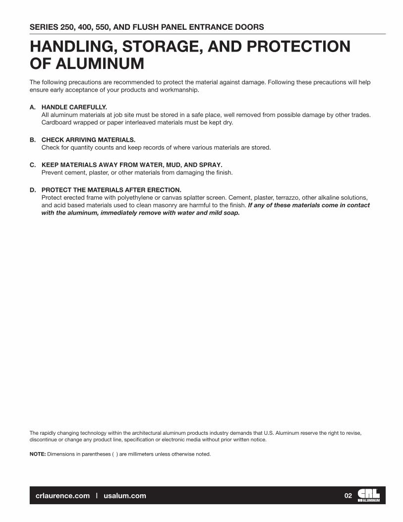
ASSEMBLY INSTRUCTIONS:1. Verify opening size. Allow for 1/4" (6.4) shim and caulk space at sides, and 1/2" (12.7) space at top of frame. (When using optional AF100 sill flashing, allow 1/4" (6.4) shim space at top of frame).2. If required, cut off top of vertical jambs to adjust frame to desired height.3. Cut templates from instructions. Align edge of template with
top of vertical and drill holes for head clips.4. Attach anchor clips for head, door header, and threshold to
jambs with provided screws.5. Butter contact surface of anchor clips with RTV408 Silicone Sealant. See DETAIL A6. Assemble head and door header to jambs as shown.7. Install hinges to door jamb(s).
1. Set frame into opening plumb and square.2. Drill holes for #12 installation screws starting 6" (152.4)
from corners and not more than 36" (914.4) O.C.3. Secure jambs and head to opening and threshold to floor with #12 screws. See DETAIL B
6. Install glass stops with glazing gaskets on both sides of glass.7. Roll-in glazing gaskets for jambs and header.
4. Snap door stop with weatherstrip into jambs and door header. Jamb stops run through.5. Place setting blocks in door header at quarter or eighth points as required, and glaze transom. Glazing sash is required vertically at Series 451 transom.
Anchor at centerof glass pocket
Anchor thresholdat center of door
DETAIL B
DOOR
ALIGN WITH TOP OF VERTICAL/HEAD
450
FRAM
E
400
FRAM
E
15/16"
1-3/16" 1-3/16"
15/16"
7/8"(22.2)
451
FR
AME
1" (2
5) G
LAS
S
ALIGN WITH TOP OF VERTICAL/HEAD
2-1/8"
2-5/16" 1-3/32"1-3/32"
SHEAR CLIP APPLICATIONUSE 23 DRILL (.154" DIA.) (3.9)
SCREW SPLINE APPLICATIONUSE #7 DRILL (.201" DIA.) (5.1)
SCREW SPLINE APPLICATIONUSE #7 DRILL (.201" DIA.) (5.1)
SHEAR CLIP APPLICATIONUSE 23 DRILL (.154" DIA.) (3.9)
TEMPLATES ARE FOR EXTREME HEAD ONLY
(30.1) (30.1)
(23.8) (23.8)
(26.1) (26.1)(58.7)
(53.9)
DETAIL A
Seal contact surface here at header using RTV408 Silicone
Fill relief tracks hereat door header using RTV408 Silicone
3/16"(4.7)
3/16"(4.7)
1/2"(12.7)
NOTE: Do not cut templates from this manual, templates are supplied inside frame boxes.

SERIES 250, 400, 550, AND FLUSH PANEL ENTRANCE DOORS
06crlaurence.com | usalum.com
NOT TO SCALE
DOOR AND FRAME PREPARATION
GLASS SIZE FORMULA AT TRANSOM
DIMENSION "B"
DIMENSION "B" +5/8"
JS405/JS455
JS405/JS455
JS417/JS467
DS040/DS047
(2) M740
JS402/JS452
DIM
ENSI
ON
"A"
DIM
EN
SIO
N "
A"
-1/8
"7/
16" m
ax.
SETT
ING
BLK
. SIZ
E
(2) SB525
DIMENSION "B" -1-1/8"
DIMENSION "B"
1S456 1S456
1427 1427
1M425 1M425
DS047
(2) M741
1S467
1S452
DIM
ENSI
ON
"A"
DIM
EN
SIO
N "
A"
-1/8
"9/
16" m
ax.
SETT
ING
BLK
. SIZ
E
(2) SB510
SERIES 400 AND 450
SERIES 451
NOTE: Use the same formulas for Flush Panel Models

SERIES 250, 400, 550, AND FLUSH PANEL ENTRANCE DOORS
07crlaurence.com | usalum.com
NOT TO SCALE
450 TUBULAR FRAME SHOWN400 AND 451 SIMILAR
FRAME UNIT FOR OFFSET PIVOT DOORWITH SURFACE CLOSER
(4) #12 X 24 X 1/2" FH(Screws included)
APK402Anchor Clip with (2) 10X2PHPSMS
Glazing Stops (2) M740 at Series 400, 450 (2) M741 at Series 451, 1T451
(2) #12-24 X 3/8"FH SMS undercut
DS040 at Series 400 DS047 at Series 450 and 451 Snap-In Door Stop with weatherstrip (Not shown at Hinge Jamb for clarity)
APK402Anchor Clip
(2) #12-24 X 3/8" FH SMS undercut (Included in pivot package)
(2) #12-24 X 3/8" FH SMS undercut
TC50000 (Modified) Anchor Clip with (2) #12-24 X 3/8" FH SMS
(4) 10X2PHPSMS
(1) ST240 #10 X 1/2" FH SMS
0P400Top Pivot frame Portion (Supplied with door hardware)
(6) ST251 #10 X 1" HH SMS
(2) ST240 #10 X 1/2" FH SMS
0P400Bottom Pivot frame Portion (Supplied with door hardware)
SCREW SPLINE INSTALLATIONFOR OPEN BACK FRAMES

SERIES 250, 400, 550, AND FLUSH PANEL ENTRANCE DOORS
08crlaurence.com | usalum.com
NOT TO SCALE
SHIM
DETAIL C
INSTALLATION INSTRUCTIONS:
ASSEMBLY INSTRUCTIONS:
Anchor at centerof glass pocket
Anchor thresholdat center of door
DETAIL B
1. Verify opening size. Allow for 1/4" (6.4) shim and caulk space at sides, and 1/2" (12.7) space at top of frame. (When using optional AF100 sill flashing, allow 1/4" (6.4) shim space at top of frame).2. If required, cut off top of vertical jambs to adjust frame to desired height.3. Cut templates from instructions. Align edge of template with
top of vertical and drill holes for head clips.4. Attach anchor clips for head, door header, and threshold to
jambs with provided screws.5. Butter contact surface of anchor clips with RTV408 Silicone Sealant. See DETAIL A6. Assemble head and door header to jambs as shown.7. Attach bottom pivot(s) to jamb(s), then attach threshold to assembly.8. Install top pivot to door header.
1. Set frame into opening plumb and square.2. Drill holes for #12 installation screws starting 6" (152.4)
from corners and not more than 24" (609.6) O.C.3. Secure jambs and head to opening and threshold to floor with #12 screws. See DETAIL B
7. Place glass setting blocks in door header at quarteror eighth points as required and glaze transom.
8. Install sash glazing bead.9. Roll-in glazing gaskets for jambs and header.
DOOR4. If pivot is not supported by finished floor, block as required. See DETAIL C.5. Snap door stops with weatherstrip into jambs and door header. Jamb stops run through.6. For 1" (25) glazing, snap jamb sash into jambs. Jamb sash runs through.
DETAIL A
Seal contact surface here at header using RTV408 Silicone
Fill relief tracks hereat door header using RTV408 Silicone
ALIGN WITH TOP OF VERTICAL/HEAD
450
FRAM
E
400
FRAM
E
15/16"
1-3/16" 1-3/16"
15/16"
7/8"(22.2)
451
FR
AME
1" (2
5) G
LAS
S
ALIGN WITH TOP OF VERTICAL/HEAD
2-1/8"
2-5/16" 1-3/32"1-3/32"
SHEAR CLIP APPLICATIONUSE 23 DRILL (.154" DIA.) (3.9)
SCREW SPLINE APPLICATIONUSE #7 DRILL (.201" DIA.) (5.1)
SCREW SPLINE APPLICATIONUSE #7 DRILL (.201" DIA.) (5.1)
SHEAR CLIP APPLICATIONUSE 23 DRILL (.154" DIA.) (3.9)
TEMPLATES ARE FOR EXTREME HEAD ONLY
(30.1) (30.1)
(23.8) (23.8)
(26.1) (26.1)(58.7)
(53.9)
3/16"(4.7)
3/16"(4.7)
1/2"(12.7)
NOTE: Do not cut templates from this manual, templates are supplied inside frame boxes.

SERIES 250, 400, 550, AND FLUSH PANEL ENTRANCE DOORS
09crlaurence.com | usalum.com
NOT TO SCALE
(TUBULAR FRAME SHOWN, OPEN BACK SIMILAR)GLASS SIZE FORMULA AT TRANSOM
SERIES 400 AND 450
SERIES 451
JS467
DS040/DS047
(2) M740
JS402/JS452
DIM
ENSI
ON
"A"
DIM
EN
SIO
N "
A"
- 1/8
"7/
16" m
ax.
SETT
ING
BLK
. SIZ
E DIMENSION "B"
DIMENSION "B" + 5/8"
JS405/JS455
JS405/JS455
JS417/
(2) SB525
DS047
(2) M741
1S467
1S452
DIM
ENSI
ON
"A"
DIM
ENSI
ON
"A" -
1/8
"9/
16"
max
.
SETT
ING
BLK
. SIZ
E
DIMENSION "B" -1-1/8"
DIMENSION "B"
(2) SB510
1S456 1S4561427 1427
1M425 1M425

SERIES 250, 400, 550, AND FLUSH PANEL ENTRANCE DOORS
10crlaurence.com | usalum.com
(2) ST251 #10 x 1" HH SMS
(2) #10X2PHSMS
at app. 18" (457.2) O.C.
(1) ST240#10 x 1/2" FH SMS
(2) ST240#10 x 1/2" FH SMS
Closermountingbracket(included incloser package)
(3) #8-32 PH(Included incloser package)
Threshold mountedbottom pivot
Threshold clipAttach to jamb with (1) #6 x 3/8"
(2) #10 x 3/8"FH SMS(Included incloser package)
M122 Glazing Sash and Glass Stop(not shown at jamb for clarity)
APK402Anchor Clip
M123 Aluminum Sash Face
P427 Filler
Cover plate
#6 x 3/8" PH
APK402Anchor Clip with (4) 10X2PHPSMS
(1) ST240#10 x 1/2" FH SMS
FRAME UNIT FOR CENTER HUNG DOORWITH OVERHEAD CONCEALED CLOSER
450 TUBULAR FRAME SHOWN400 AND 451 SIMILAR
SCREW SPLINE INSTALLATIONFOR OPEN BACK FRAMES
NOT TO SCALE
SERIES 250, 400, 550, AND FLUSH PANEL ENTRANCE DOORS
11crlaurence.com | usalum.com
NOT TO SCALE
DETAIL C
INSTALLATION INSTRUCTIONS:
ASSEMBLY INSTRUCTIONS:
Anchor at centerof glass pocket
Anchor thresholdat center of door
DETAIL B
1. Verify opening size. Allow for 1/4" (6.4) shim and caulk space at sides, and 1/2" (12.7) space at top of frame. (When using optional AF100 sill flashing, allow 1/4" (6.4) shim space at top of frame).2. If required, cut off top of vertical jambs to adjust frame to desired height.3. Cut templates from instructions. Align edge of template with top of vertical and drill holes for head clips.4. Attach anchor clips for head, door header, and threshold to jambs with provided screws.5. Butter contact surface of anchor clips with RTV408 Silicone Sealant. See DETAIL A6. Assemble head and door header to jambs as shown.7. Install bottom pivot in threshold.
1. Set frame into opening plumb and square.2. Drill holes for #12 installation screws starting 6" (152.4) from corners and not more than 24" (609.6) O.C.3. Secure jambs and head to opening and threshold to floor with #12 screws. See DETAIL B
6. Place glass setting blocks in door header at quarter or eighth points as required and glaze transom.7. Install sash glazing bead.
8. Roll-in glazing gaskets for jambs and header.
DOOR
4. Install transom sash. Horizontal sash runs through at door door header. Vertical sash abutts over horizontal sash and is mitered at outside to allow for horizontal glazing bead installation. See DETAIL C5. Attach sash to door header with #6 x 3/8" PH at 18" (457.2) O.C.
3/16" @ 15Min. notch
1/2" @ 45Jamb sash
Header sash
DETAIL A
Seal contact surface here at header using RTV408 Silicone
Fill relief tracks hereat door header using RTV408 Silicone
ALIGN WITH TOP OF VERTICAL/HEAD
450
FRAM
E
400
FRAM
E
15/16"
1-3/16" 1-3/16"
15/16"
7/8"(22.2)
2-1/8"
SCREW SPLINE APPLICATIONUSE #7 DRILL (.201" DIA.) (5.1)
SHEAR CLIP APPLICATIONUSE 23 DRILL (.154" DIA.) (3.9)
TEMPLATES ARE FOR EXTREME HEAD ONLY
(30.1) (30.1)
(23.8) (23.8)
(53.9)
3/16"(4.7)
NOTE: Do not cut templates from this manual, templates are supplied inside frame boxes.

SERIES 250, 400, 550, AND FLUSH PANEL ENTRANCE DOORS
12crlaurence.com | usalum.com
NOT TO SCALE
DIMENSION "B"-7/8" (19.4)
DIMENSION "B"
RS110 (Typ.)RS200 (Typ.)
RS110 Deep PocketRS200 Shallow Pocket
JS401/ JS451
JC407/JC457
JS402/J402JS452/J452
DIM
EN
SIO
N "
A"
DIM
EN
SIO
N "
A"
-1/8
" (3
.2)
7/16
" (1
1.1)
max
.
SE
TTIN
G B
LK. S
IZE
(4) SB045
M122
M123
M122
M123
P427
M122M123
JS401/ JS451
GLASS SIZE FORMULA AT TRANSOM(OPEN BACK FRAME SHOWN, TUBULAR SIMILAR)

SERIES 250, 400, 550, AND FLUSH PANEL ENTRANCE DOORS
13crlaurence.com | usalum.com
NOT TO SCALE
(2) #10-32 x 3/4" FH SMS
Aluminum shim(2) Aluminum shims
(4) #10-32 x 3/4" FH SMS
Closer mounting bracket
Header mounting bracket Option: APK402 anchor clip may also be used to fasten header to jamb when using a Jackson closer with 105º swing HO and offset pivot.
Closer mounting bracket
3/4" x 3-1/2" x 1/4" aluminum shim
Closermountingbracket
To mount closer into 2"(50.8) high headers a 1/4" (6.4) shim is required.For balance of header installation see pages 47 through 55.
Secure closer mounting bracket toheader with (2) #10-32 x 3/4" F.H.
1/8" shim(included in closer package)
(14.3)
Remove gussets
Remove gussetsand flange
CLIPS SHOWN INVERTED TO VIEW BOTTOM AT WORK AREA
1/8" SHIM
JACKSON OHCC with butthung door 90º swing
JACKSON OHCC with offsetpivoted door
JACKSON OHCC with butthung door 105º swing
9/16" VARIES
TYPE "A"STANDARD CLIP
TYPE "B"MODIFIED CLIP
TYPE "C"DOUBLE MODIFIED CLIP
HEADER FOR JACKSON OVERHEAD CONCEALED CLOSER WITH OFFSET ARM

SERIES 250, 400, 550, AND FLUSH PANEL ENTRANCE DOORS
14crlaurence.com | usalum.com
NOT TO SCALE
Cover Plate
Clamping Box
(2) Mountingscrews
Holesby U.S.Aluminum
Pinning holeby installer
Door portion of bottom pivot
(3) 1/4-20 RH MS
Adjusting screw
Top Arm centering screws
Top Arm adjusting screw
Top Arm
NARROW STILE
MEDIUM AND WIDE STILE
Top Arm DETAIL A
DETAIL B
DETAIL C
DETAIL A
SIDE LOAD CENTER PIVOT DOOR WITH JACKSON OVERHEAD CONCEALED CLOSER
1. Install top arm and door portion of bottom pivot as shown in DETAIL A. 2. Position door upright in closed position on the outside of frame. 3. Lift onto floor pivot and tilt to vertical. 4. Adjust top arm as required to receive closer spindle. 5. Install top clamping block using tool provided in closer package see DETAIL B. 6. Drill two holes in top of door to attach cover plate see DETAIL C. If vertical adjustment is required, loosen or tighten adjusting screw at bottom pivot (door portion). 7. Adjust top arm centering screws to center door in frame.

SERIES 250, 400, 550, AND FLUSH PANEL ENTRANCE DOORS
15crlaurence.com | usalum.com
NOT TO SCALE
BUTT HINGE DOOR WITH JACKSON OVERHEAD CONCEALED CLOSER
90º SHOWN
5
3
1
Slide Channel
Channel Spacer(shop applied)
Closer Arm
Arm Cover
1. Mount slide channel with (3) #8-32 x 3/8" FH MS. Reverse side block if necessary for proper installation. See closer template.
2. Attach butt hinges to door. Install door by fastening hinges to frame. Backup plates for door and frame are factory installed.
3. Remove arm pin retainer using "C" clip pliers. With door in open position, slip arm over slide pin and secure with pin retainer.
4. Adjust closer to desired door speed.
5. Install arm cover with #8 x 1-1/2" FH screws (provided).
SERIES 250, 400, 550, AND FLUSH PANEL ENTRANCE DOORS
16crlaurence.com | usalum.com
NOT TO SCALE
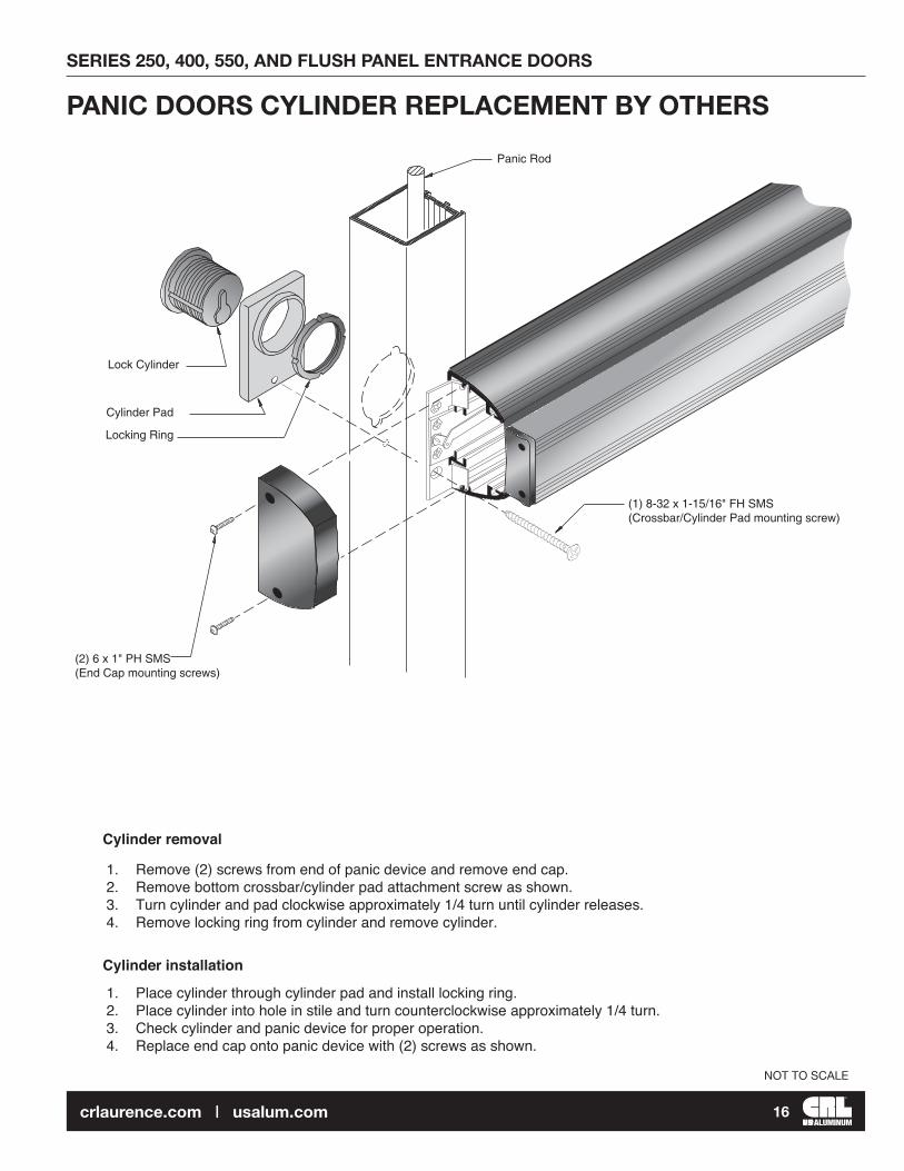
(1) 8-32 x 1-15/16" FH SMS(Crossbar/Cylinder Pad mounting screw)
(2) 6 x 1" PH SMS(End Cap mounting screws)
Locking Ring
Cylinder Pad
Lock Cylinder
Panic Rod
Cylinder removal
Cylinder installation
1. Remove (2) screws from end of panic device and remove end cap.2. Remove bottom crossbar/cylinder pad attachment screw as shown.3. Turn cylinder and pad clockwise approximately 1/4 turn until cylinder releases.4. Remove locking ring from cylinder and remove cylinder.
1. Place cylinder through cylinder pad and install locking ring.2. Place cylinder into hole in stile and turn counterclockwise approximately 1/4 turn.3. Check cylinder and panic device for proper operation.4. Replace end cap onto panic device with (2) screws as shown.
PANIC DOORS CYLINDER REPLACEMENT BY OTHERS
SERIES 250, 400, 550, AND FLUSH PANEL ENTRANCE DOORS
17crlaurence.com | usalum.com
NOT TO SCALE
1-9/16"
25/32"1-1/16"
7/8"
Face of doorheader
(39.7)
(27)
(19.8)
(22.
2)
(2) .136" (3.5) Dia.holes (#29 drill)
Jamb edge atactive stile
1-9/16"
25/32"1-1/16"
7/8"
(4) .136" (3.5) Dia. holes (#29 drill)
(39.7)
(27)
(19.8)
(22.
2)
(2) Strike plate cut-outs
Face of doorheader
CL of Door pairs
Front edgeof Threshold
Threshold endat active stile
Front edgeof Threshold
A B
Face of frame
CL CL
CL CLCL
CD
NARROW
MEDIUM
WIDE
VANGARD MEDIUM
VANGARD WIDE
DOOR STILE TYPE
1-7/32" (31) 2-3/8" (60.3) 7/8" (22.2) 1-5/8" (41.3)
DIMENSION DIMENSION DIMENSION DIMENSION
2-11/16" (68.3) 5-3/8" (135.5) 7/8" (22.2) 1-5/8" (41.3)
4-3/16" (106.4) 8-3/8" (212.7)
5-1/4" (133.4)N/A N/A
N/A N/A 8-3/4" (222.3)
7/8" (22.2) 1-5/8" (41.3)
7/8" (22.2) 1-5/8" (41.3)
7/8" (22.2) 1-5/8" (41.3)
3/4"(19.1)
17/32"(13.5)
(2) Strike cut-outs
TH250THRESHOLD
DC
Face of frame
HEADER AT SINGLE DOOR HEADER AT DOOR PAIRS
THRESHOLD AT SINGLE DOOR THRESHOLD AT DOOR PAIRS
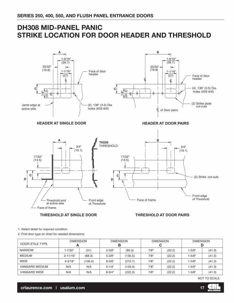
1. Select detail for required condition.2. Find door type on chart for needed dimensions.
A B C D
17/32"(13.5)
3/4"(19.1)
BA
C C
DH308 MID-PANEL PANIC STRIKE LOCATION FOR DOOR HEADER AND THRESHOLD

SERIES 250, 400, 550, AND FLUSH PANEL ENTRANCE DOORS
18crlaurence.com | usalum.com
NOT TO SCALE
Front strike edge alignswith inside edge of door.
Strike
Panic housing
P0501-3/4" (44.5) long
Shim at strike location
Lower door stop
Upper door stop
Strike
Adjustingplate
P0501-3/4" (44.5) long
TOP VIEW
ISOMETRIC VIEW OF ASSEMBLY
centered on Strike
"PANIC DOORS" with DH300 RIM PANIC

SERIES 250, 400, 550, AND FLUSH PANEL ENTRANCE DOORS
19crlaurence.com | usalum.com
NOT TO SCALE
(Slotted holes allow for door adjustment)
(2) 1/4-20 FH SMS
(2) 1/4-20 FH SMS
Cat. No. 20534628 Top Pivot KitNOTE: C of pivot and C of header must align
Pivot retractor screw
L L
Spacer channel(factory installed)
SERIES 250 NARROW STILE
D201
D201
SERIES 400 MEDIUM STILE
SERIES 550 WIDE STILE
WS100
Spacer channel(factory installed)
Cat. No. 20534628 Top Pivot Kit
CENTER PIVOT - TOP PORTION FOR SURFACE CLOSER OR FLOOR CLOSER

SERIES 250, 400, 550, AND FLUSH PANEL ENTRANCE DOORS
20crlaurence.com | usalum.com
NOT TO SCALE
Cat. No. 20944Threshold MountBottom Pivot Set
1/2" (12.7) Dia. hole
(1) 10-32 PH SMSInstall after doorpivot has been adjusted
(2) 1/4-20 PH SMSwith lock washers
CL
BOTTOM DOOR VIEW
FRONT DOOR VIEW
7/16" (11.1)Dia. hole foradjusting screw
(1) HOLE FOR #10-32 PH SMS(AFTER PIVOT HAS BEEN ADJUSTED)
DRILL & TAP(2) HOLES FOR 1/4-20 PH SMS
2-3/4"(69.85)
3-3/4" 1-3/4"(95.3) (44.5)
1-1/16"(26.9)
CENTER PIVOT - BOTTOM PORTION
SERIES 250, 400, 550, AND FLUSH PANEL ENTRANCE DOORS
21crlaurence.com | usalum.com
NOT TO SCALE
(2) 1/4-20 x 1/2" (12.7)Hex Head Cap screws
(2) 1/4-20 x 1/2" (12.7) FHMS
0P400 Pivot Set
Factory installedin Entrance Package doors
Drill and Csk. for(2) 1/4-20 FHMS
17/32"
5/8"
1-3/16"
1/4"
1/8"
1/2"
7/16"
(13.5)
(15.9)
(30.2)
(6.4)
(3.2)
(12.7)
(11.1)
(21.4)27/32"
CL
CROSS SECTION
3/4"
7/16"
1-1/4"(31.8)
(11.1)
(19.1)
DRILL (2) .257" (6.5) holes
0P400 Pivot Set
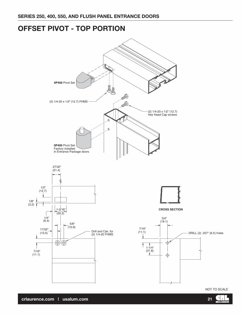
OFFSET PIVOT - TOP PORTION

SERIES 250, 400, 550, AND FLUSH PANEL ENTRANCE DOORS
22crlaurence.com | usalum.com
NOT TO SCALE
Drill (2) (6.5).257" DIA. holes
(2) #12-24 x 1/2"FHMS (undercut)(included in pivot package)
0P400Bottom frameportion pivot
Adjustablepivot pin
0P400Factory installedin door entrancepackage
(2) #12-24 x 3/8"FHMS (undercut)
(2) 1/4"-20 x 1/2"Hex Head Cap screws
3/4"(19.1)
1-5/16"(23.8)
3/4"(19.1)
1-1/4"(31.8)
1/8"(3.9)
7/16"(11.1)
1-1/16"(27)
21/64"(8.7)
25/32"(19.8)
1-9/16"
1-23/64"
23/64"
(2) DRILL & CTSK. for#12-24 FHMS (undercut)
1-7/8"1-3/32" 1-3/16"(47.6)(27.8) (20.6)
(9.1)
(34.5)
(39.7)
(2) DRILL & CTSK. for#12-24 FHMS (undercut)
OFFSET PIVOT - BOTTOM PORTION

SERIES 250, 400, 550, AND FLUSH PANEL ENTRANCE DOORS
23crlaurence.com | usalum.com
NOT TO SCALE
DH022Intermediate Pivot Set
Cap screw
Pivot pin(dotted)
DOES NOT REQUIRE BACK-UP PLATE
PROCEDURE AHang door on top and bottom pivots. With door in closed position, slide intermediate pivot (assembled together) into frame and pivot (assembled together) into frame anddoor slots. Open door to secure pivot with fasteners provided. See DETAIL A
PROCEDURE BInstall pivot leaves on frame and door. Remove cap screw from jamb portion of pivot and lower pin to clear. Hang door on top and bottom pivots. Raise pivot pin, as required and replace cap screw.See DETAIL B
To remove existing doors with intermediate pivots, Remove cap screw and lower pivot pin to clear.
DETAIL A
DETAIL B
DH022 INTERMEDIATE PIVOT

SERIES 250, 400, 550, AND FLUSH PANEL ENTRANCE DOORS
24crlaurence.com | usalum.com
NOT TO SCALE
DH010 INTERMEDIATE PIVOT (RIXON OR DOR-O-MATIC M-19 SIMILAR)
Cat. No. 2302711 Backing Plate (factory installed)
Cat. No. 41J190Intermediate Pivot
(10) 1/4-20 x 5/8" FH SMS
Pivot pin(dotted)
Cap screw
PROCEDURE AHang door on top and bottom pivots.Swing door open to 180º and install DH010 (assembledtogether) with (10) 1/4-20 FH SMS provided. See DETAIL A
PROCEDURE BDo not install top pivot frame portion.Install pivot leaves on frame and door with screwsprovided. Place door upright in the 95º, or more, openposition (to clear header). Lift door onto intermediatepivot pin and floor pivot. Hold down top pivot pin toinstall top pivot frame portion. See DETAIL B
PROCEDURE CInstall pivot leaves on frame and door with screwsprovided. Remove cap screw from jamb portion of pivotand lower pin to clear. Hang door on top and bottompivots. Raise pivot pin, as required, and replace capscrew. See DETAIL C
To remove existing doors with intermediate pivots, remove cap screw and lower pivot pin to clear.
DETAIL C
DETAIL ADETAIL B
Condition 1: Door can open to 180º...................................................................................................USE PROCEDURE A, B, or C Condition 2: Door can open more than 95º but less than 180º .........................................................USE PROCEDURE A, B, or C Condition 3: Door can open less than 95º .........................................................................................USE PROCEDURE A, B, or C

SERIES 250, 400, 550, AND FLUSH PANEL ENTRANCE DOORS
25crlaurence.com | usalum.com
NOT TO SCALE
DH009Butt hinge
(4) 5/32" (40) R.
Cat. No. 2302711Frame backing plate factory installed
4-17/32"
1-1/4"
1/2"
4-17/32"
1/2"
1-1/4"
(114.3)
(12.7)
(31.8)
(31.8)
(12.7)
(114.3)
1-1/16"
1-7/16"
7/16"
(36.5)
(27)
(11.1)
1-1/16"
1-7/16"
7/16"
(36.5)
(27)
(11.1)
8"(203.2)
FRONT VIEW SIDE VIEW SIDE VIEW FRONT VIEW
.134"(3.4)
FRAME PREPARATION DOOR PREPARATION
Prepare frame and door for hinges,as shown.Back-up plates are factoryinstalled in prepared doors and frames.Install butt hinges in door. Setdoor in place and fasten hingesto frame.
.134"(3.4)
DH009 BUTT HINGE 4-1/2" x 4" (38.1 x 101.6)

SERIES 250, 400, 550, AND FLUSH PANEL ENTRANCE DOORS
26crlaurence.com | usalum.com
NOT TO SCALE
JACKSON OVERHEAD CONCEALED CLOSER FOR CENTER PIVOTED DOOR
Closer mounting bracket(Bracket also is used as head tojamb clip for frame fabrication)
3
2
1
Angle Bracket
Balance of Plate
JACKSON CLOSERSee template forcloser adjustments
Cover Plate(14" long)
Closer mounting bracket is already installed (See FRAME UNITS installation instructions).1. Mount angle bracket to closer with (2) 1/4-20 hex head SMS and (2) washers.2. Install (2) 1/4-20 x 5/8" Fillister Head MS into lugs of closer. Do not tighten screws.3. Install (2) 1/4-20 x 7/8" FH SMS* with (2) 1/4-20 nuts and washers in header.4. Insert closer lugs into mounting bracket at an angle and raise closer opposite end to align
mounting screws with angle bracket holes. Secure bracket to mountingscrews using (2) nuts and washers.5. Tighten Fillister Head screws.6. Snap in filler plate.
*For 2" x 4-1/2" header, longer screws are provided.
*

SERIES 250, 400, 550, AND FLUSH PANEL ENTRANCE DOORS
27crlaurence.com | usalum.com
NOT TO SCALE
1
2
3 5
6
7
Closer mounting bracket(corner bracket)
Angle bracket
Closer spindle
Adjusting valve
Closer arm
Cover plate
1. Mount corner bracket intoheader with (2) 10-32 x 3/8"
FH SMS. See pages 27 and 29 for bracket location.
2. Mount angle bracket to closerwith (2) 1/4-20 x 1/2"
Hex Head SMS and washers.
3. Install (2) 1/4-20 x 1/2" Fillister Head SMS with washers into lugs of closer.
Do not tighten screws.
4. Set closer onto header andalign angle bracket holeswith holes in header. Closerlugs shall rest on cornerbracket.
5. Fasten angle bracket to header with (2) 10-24 x 3/8" FH SMS Tighten Fillister Head screws.
6. Install cover plate and secureto angle with (2) 10-24 x 3/8"
FH SMS
7. Mount arm on spindle and securewith 1/4-20 x 7/8" Socket HeadCap Screw.
JACKSON OVERHEAD CONCEALED CLOSERFOR OFFSET PIVOTED DOOR
for door preparation and slide channel installation see page 54
JACKSON OVERHEAD CONCEALED CLOSER FOR OFFSET PIVOTED DOOR

SERIES 250, 400, 550, AND FLUSH PANEL ENTRANCE DOORS
28crlaurence.com | usalum.com
NOT TO SCALE
JACKSON OVERHEAD CONCEALED CLOSER FOR OFFSET PIVOTED DOOR WITH 90º SWING
Drill and csk. 82 for (4) #10 FH
Exterior edge
Type "B"Header anchorbracket
Type "C" Closer mounting bracket
C of spindleL
Drill and csk. 82 for (4) #10 FH
Jackson closer
1-7/16"
7/16"(11.1)
(36.5)
2-3/4"
5/8"
(69.9)
(15.9)
(50.8)2"
of closerCL
3-3/4"(95.3) 9-7/16" 3/4"
8-19/32"
7" 1-1/4"
(139.7)
(243.7)
(177.8) (31.8)
(19.1)
(79.4)
(11.1)7/16"
3-1/8"
3-3/4"
11-13/16"1-3/4"(44.5)
(300)
(95.3)3/8" Dia. clearance hole
7/16" x 1-1/4"clearance slot
1-3/4" Dia.clearance hole
1/8"(3.2)
3-3/4"
2"(50.8)
(95.3)
HEADER SIDE VIEW
HEADER TOP VIEW
HEADER BOTTOM VIEW
1-3/4" x 4-1/2" (44.5 x 114.3) Header shown
1-3/4" x 4" (44.5 x 101.6) Header similar
2" x 4-1/2" (50.8 x 114.6) Header requires the use of a shim
1-7/16"
(36.5)
2"
1"
(50.8)
(25.4)
(2) 5/16" Dia.access holes
NOTE: Closer bracket needs to be modified (by installer) to clear header portion of top pivot.
cover plate
3/8"(9.5)
3/8"(9.5)
HEADER PREPARATION

SERIES 250, 400, 550, AND FLUSH PANEL ENTRANCE DOORS
29crlaurence.com | usalum.com
NOT TO SCALE
JACKSON OVERHEAD CONCEALED CLOSER FOR OFFSET PIVOTED DOOR WITH 105º SWINGHEADER PREPARATION
Drill and csk. 82 for (4) #10 FH
Drill and csk. 82 for (2) #8-32 F.H.
Exterior edge
Type "B" Header anchor bracket(or Optional APK402 anchor clip)
Type "A" Closer mounting bracket
C of spindleL
Drill and csk. 82 for (4) #10 FH
Jackson closer
2-3/16"
7/16"(11.1)
(55.6)
2-3/4"
5/8"
(69.9)
(15.9)
(50.8)2"
of closerCL
4-1/2"(114.3) 9-7/16" 3/4"
8-19/32"
7" 1-1/4"
(139.7)
(243.7)
(177.8) (31.8)
(19.1)
(79.4)
(11.1)7/16"
3-1/8"
4-1/2"
7/16"
12-9/16"1-3/4"(44.5)
(363.5)
(11.1)
(114.3)
3/8" DIA.clearance hole
7/16" x 1 1/4"clearance slot
1-3/4" DIA.clearance hole
1/8"(3.2)
3-3/4"
2"(50.8)
(95.3)(79.4)
7/16"(11.1)
3-1/8"
HEADER SIDE VIEW
HEADER TOP VIEW
HEADER BOTTOM VIEW
1-3/4" X 4-1/2" (44.5 x 114.3) Header shown1-3/4" x 4" (44.5 x 101.6) Header similar2" x 4 1/2" (50.8 x 114.6) Header requires the use of a shim
cover plate
3/8"(9.5)
3/8"(9.5)

SERIES 250, 400, 550, AND FLUSH PANEL ENTRANCE DOORS
30crlaurence.com | usalum.com
NOT TO SCALE
C of Spindle
Concealed closer
L
C of fasteners for closer mountingL
Slide channel and spacer
"A"
"B"
17-3/16"
6-7/16"1-1/2"
"C"
7/16"5/8"
(15.9)
(436.6)
(163.5)(11.1)
DOOR TYPE HOLDOPEN
DIMENSION"C"
OFFSET PIVOT(0P400)
BUTT HINGES
90º
105º
90º
105º
4-15/16"(125.4)
4-11/16"(119.1)4-1/16"(103.2)3-7/8"(98.4)
DOOR TYPE HOLDOPEN
DIMENSION"A"
OFFSET PIVOT(OP400)
BUTT HINGES
90º OR 105º
90º
105º
2-3/4"(69.9)
3-3/4"(95.3)
4-1/2"(114.3)
105º
90º
3-3/4"(95.3)2-7/8"(73.0)
7/16"(11.1)
1-7/16"(36.5)
2-3/16"(55.6)
9/16"(14.3)
1-7/16"(36.5)
DIMENSION"B"
CENTER PIVOT
SLIDE CHANNEL LOCATION IN TOP RAIL FOR OFFSET ARM
DOOR VIEW FROM INSIDE
REFERENCEPAGE
25
28
27
15
15
(38.1)
VIEW OF HEADER AT CLOSER
OFF-SET ARM COVER CHANNEL
15"(381.0)
1-1/4"(31.8)
3/4"(19.1)
Notch out
DA201
RIGHT HAND SHOWN LEFT HAND OPPOSITE
JACKSON OVERHEAD CONCEALED CLOSERCLOSER LOCATION IN HEADER

SERIES 250, 400, 550, AND FLUSH PANEL ENTRANCE DOORS
31crlaurence.com | usalum.com
NOT TO SCALE
OFFSET PIVOT DOOR - FLOOR CLOSER BOTTOM ARM FOR RIXON FLOOR CLOSURE (DOR-O-MATIC SIMILAR)
1/4"
3/8" (9.5)
(6.4)
3-3/4"(95.3)
(22.2)7/8"
for doors with1/2" threshold
for doors withno threshold
Door bottom adaptor.Use modified adaptor fordoors with no threshold.
Door Bottom Adaptor.(Factory installed in prepared doors)
Door Bottom Arm (Handed)
(4) 1/4-20 x 5/8" FH SMSto secure bottom arm tobottom adaptor.
(4) 1/4-20 FH SMSto secure bottomadaptor to rail andcorner block.

SERIES 250, 400, 550, AND FLUSH PANEL ENTRANCE DOORS
32crlaurence.com | usalum.com
NOT TO SCALE
DH008 FLUSH BOLTNARROW STILE SHOWN, MEDIUM AND WIDE STILES SIMILAR
4-1/4" (107.9)
1/2" (12.7)
9-1/
4" (2
34.9
) LO
CA
TIO
N F
RO
M B
OTT
OM
EDG
E O
F D
OO
R9-
1/4"
(234
.9) L
OC
ATI
ON
FR
OM
TO
PED
GE
OF
DO
OR
9-1/4" (234.9)
DIM
ENSI
ON
SH
OU
LD N
OT
EXC
EED
70"
(177
.8 c
m) C
UST
OM
HEI
GH
T D
OO
RS
15/16"(23.8)
.156" R.(4 mm)
5/16"(7.9)
5/16"(7.9)
7/8" (22.2)
7/8" (22.2)
Drill andcountersinkfor #8 FHscrew 6 places.
1/2"(12.7)Latching
Rod
Rod Guide
DETAIL B
DETAIL A
DETAIL C
NOTE: Topflush bolt cut-out location for door opening height of 84" (213.4 cm) or less should be 9-1/4" (234.9) from top edge of door. See DETAIL A
1. Install top and bottom flush bolts with (2) #8 FH screws each.2. Place each lever in the lock position.3. Adjust flush bolt rods to extend 1/2" (12.7) beyond ends of door stile. See DETAIL B4. Insert rod guides over rods and into stile at top and bottom. Secure guides with (1) #8 FH screw each.5. Flip levers to retract both flush bolts.
1/2" (12.7)
9-1/4" (234.9)
SERIES 250, 400, 550, AND FLUSH PANEL ENTRANCE DOORS
33crlaurence.com | usalum.com
NOT TO SCALE
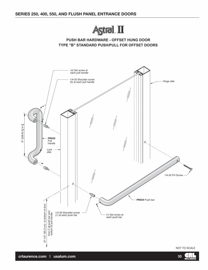
1/4-20 Shoulder screw(2) at each pull handle
(4) Set screw at each pull handle
Hinge stile
Lockstile
37-1
/2"
(95.
3 cm
) to
bot
tom
of d
oor
PR034 Push bar
PR032Pullhandle
1/4-20 Shoulder screw(1) at each push bar (1) Set screw at
each push bar
from
C o
f pus
h ba
r and
botto
m o
f pul
l han
dle
L
9" (2
28.6
) C to
CL
L
1/4-20 FH Screw
PUSH BAR HARDWARE - OFFSET HUNG DOORTYPE "B" STANDARD PUSH/PULL FOR OFFSET DOORS
R

SERIES 250, 400, 550, AND FLUSH PANEL ENTRANCE DOORS
34crlaurence.com | usalum.com
NOT TO SCALE
PR032 Pull Handle
1/4-20 Shoulder screw(2) at each pull handle
Lock stile
Hinge stile
Panic device
C of pullhandleL
PUSH/PULL HARDWARE - PANIC DOOR
R
37-1
/2"
(95.
3 cm
) at c
once
aled
pan
ic 9" (2
28.6
) C to
CL
L

SERIES 250, 400, 550, AND FLUSH PANEL ENTRANCE DOORS
35crlaurence.com | usalum.com
CRL M64 Smooth Texture Modified Polyurethane Construction Sealant
CRL Saint-Gobain/Norton V2100 Thermalbond® Structural
Glazing Spacer Tape
CRL Door JackCAT. NO. DJ1
CRL Cordless ScrewdriverCAT. NO. LD823
CRL Portable Miter Saw 10" CAT. NO. LS1040
CRL Nordic Carbide Saw Blade
CAT. NO. CSB10X100AX
CRL Cougar Carbide Saw Blade
CAT. NO. CT10X100
CRL Digital Laser Level Tool
CAT. NO. 406065
CRL Soft-Face Power HitterCAT. NO. ST57532
CRL Hard Hat CAT. NO. ES3452
JOB SITE ESSENTIALSHelpful Tools and Supplies for Installing CRL U.S. Aluminum Entrances, Storefronts, Windows, and Curtain Wall Systems
CRL 95C Silicone Building Sealant
CRL RTV408 Neutral Cure Silicone
CRL 33S Acetic Cure Silicone Sealant
CRL12:1 Ratio Strap Frame Caulking Gun
CAT. NO. GA1203
CRL Complete Set of Seven All Stainless Steel Spatulas
CAT. NO. AB958G
CRL Backer Rod Roller Tool
CAT. NO. SBRR
CRL M66 Grainy Texture Modified Polyurethane Construction Sealant
CRL PHS Series Plastic Horseshoe Shims
CRL Vacuum Cup CAT. NO. S7950
CRL BOCBR Series Open Cell Backer Rod

SERIES 250, 400, 550, AND FLUSH PANEL ENTRANCE DOORS
36crlaurence.com | usalum.com
CRL Gasket RollerCAT. NO. VR10
CRL Gasket CutterCAT. NO. MC80N
CRL Glass CleanerCAT. NO. 1973
CRL Glass WipesCAT. NO. 1550
CRL Tape MeasureCAT. NO. 54125
CRL Glazier’s Rule HolderCAT. NO. RH670
CRL Phenolic L SquareCAT. NO. L48
CRL Spring ClampCAT. NO. JC3202HT
CRL Glass Marking PencilCAT. NO. GM44
CRL Belt SanderCAT. NO. LD321
CRL Glass Grinding Belts CAT. NO. CRL3X21120X
CRL All Terrain DollyCAT. NO. ATD1
CRL GlovesCAT. NO. KF1TL
CRL Bond Breaker Tape
CRL Glass Cutter CAT. NO. TC17B
CRL Running Pliers CAT. NO. PPG1
CRL Utility KnifeCAT. NO. K82
CRL Cordless Driver/DrillCAT. NO. LD147
CRL Utility Knife BladesCAT. NO. 1992C
CRL 96" Phenolic Straight Edge
CAT. NO. SEP96