Embed Size (px)
Citation preview
ContentsDescription Page
1: Introduction . . . . . . . . . . . . . . . . . . . . . . . . . . . . 22: Features, Functions, Benefits, and
Specifications . . . . . . . . . . . . . . . . . . . . . . . . . . . 53: VaultGard Functional Overview . . . . . . . . . . . . . 64: Alarms . . . . . . . . . . . . . . . . . . . . . . . . . . . . . . . 125: Logs . . . . . . . . . . . . . . . . . . . . . . . . . . . . . . . . . 136: VaultGard Set-up and Configuration . . . . . . . . 177: Device Configuration . . . . . . . . . . . . . . . . . . . . 468: Field Bus Configuration . . . . . . . . . . . . . . . . . . 689: System Setup Using the Serial Port . . . . . . . . 7410: Documentation . . . . . . . . . . . . . . . . . . . . . . . 77
September 2016Supersedes March 2014Instruction Booklet IL02400002E
VaultGardE
Instruction Booklet
2
Instruction Booklet IL02400002ESeptember 2016
EATON www.eaton.com
VaultGard
Instruction Booklet
Section 1: Introduction1.1 General Information
The VaultGardE from Eaton is the next generation communications product for Network Protectors, providing monitoring and remote control for vault systems . Certain to be your number one preventive maintenance tool, the VaultGard will discover network issues before they cause costly system-wide problems .
Incorporating the latest in Eaton’s innovative technology, the VaultGard can connect up to 32 devices through existing shielded twisted pair (STP) cable, and is rated for the harsh environmental stresses typically found in underground vaults .
With easy to navigate, on-board web pages accessible through Wi-Fi, cellular, or Ethernet connectivity, the VaultGard can efficiently interact with a variety of network relays . Additionally, data can link to existing Supervisory Control and Data Acquisition (SCADA) systems via DNP 3 .0 protocol .
The integrated graphics display provides expanded capabilities and enhanced functionality that tracks such vital network protector per-formance metrics as:• Device (address including status and MPCV relay reason codes);• Breaker position and alarms;• Phase currents;• Network, transformer, and phasing voltages;• Operations counter;• Power metrics: Real (kW), Reactive (VAR), and Power factor;• Positive sequence angle and positive sequence voltage;• Sensor input: captures wireless current sensor and temperature
data; and• Real time MPCV vector graphic display .
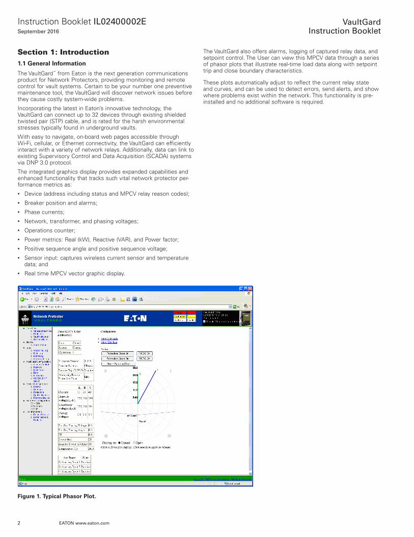
Figure 1. Typical Phasor Plot.
The VaultGard also offers alarms, logging of captured relay data, and setpoint control . The User can view this MPCV data through a series of phasor plots that illustrate real-time load data along with setpoint trip and close boundary characteristics .
These plots automatically adjust to reflect the current relay state and curves, and can be used to detect errors, send alerts, and show where problems exist within the network . This functionality is pre-installed and no additional software is required .
3
Instruction Booklet IL02400002ESeptember 2016
EATON www.eaton.com
VaultGard
Instruction Booklet
1.2 Hardware
The VaultGard is housed in a secure enclosure with numerous input and output ports to support many applications . Some of these fea-tures include:
• Support for up to 32 devices on STP cable;• DNP 3 .0 SCADA interface via RS-485 serial DNP;• DNP UDP/IP & TCP/IP uplinks;• RS-485 DNP 3 .0 sub-network for third party DNP communicating
devices;• Wireless functionality to capture sensor data;• Port for remote connectivity to the unit: Wi-Fi (WAP), cellular, LAN• Configurable threshold-based alarming with e-mail notification;• Real-time clock for historical logging of captured and time
stamped data; and• Monitoring of the remote digital inputs and outputs as well as
third party devices on accepted protocols .
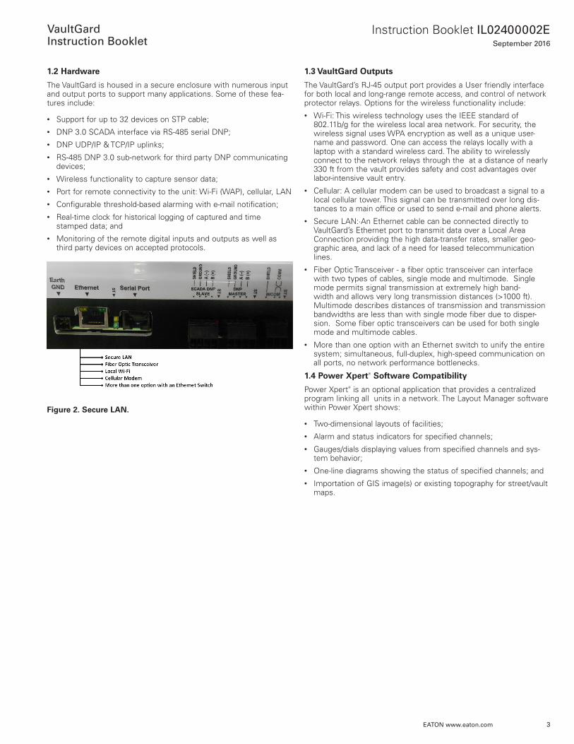
Figure 2. Secure LAN.
1.3 VaultGard Outputs
The VaultGard’s RJ-45 output port provides a User friendly interface for both local and long-range remote access, and control of network protector relays . Options for the wireless functionality include:• Wi-Fi: This wireless technology uses the IEEE standard of
802 .11b/g for the wireless local area network . For security, the wireless signal uses WPA encryption as well as a unique user-name and password . One can access the relays locally with a laptop with a standard wireless card . The ability to wirelessly connect to the network relays through the at a distance of nearly 330 ft from the vault provides safety and cost advantages over labor-intensive vault entry .
• Cellular: A cellular modem can be used to broadcast a signal to a local cellular tower . This signal can be transmitted over long dis-tances to a main office or used to send e-mail and phone alerts .
• Secure LAN:·An Ethernet cable can be connected directly to VaultGard’s Ethernet port to transmit data over a Local Area Connection providing the high data-transfer rates, smaller geo-graphic area, and lack of a need for leased telecommunication lines .
• Fiber Optic Transceiver - a fiber optic transceiver can interface with two types of cables, single mode and multimode . Single mode permits signal transmission at extremely high band-width and allows very long transmission distances (>1000 ft) . Multimode describes distances of transmission and transmission bandwidths are less than with single mode fiber due to disper-sion . Some fiber optic transceivers can be used for both single mode and multimode cables .
• More than one option with an Ethernet switch to unify the entire system; simultaneous, full-duplex, high-speed communication on all ports, no network performance bottlenecks .
1.4 Power XpertT Software Compatibility
Power XpertT is an optional application that provides a centralized program linking all units in a network . The Layout Manager software within Power Xpert shows:
• Two-dimensional layouts of facilities;• Alarm and status indicators for specified channels;• Gauges/dials displaying values from specified channels and sys-
tem behavior;• One-line diagrams showing the status of specified channels; and• Importation of GIS image(s) or existing topography for street/vault
maps .
4
Instruction Booklet IL02400002ESeptember 2016
EATON www.eaton.com
VaultGard
Instruction Booklet
1.5 Additional Functionality
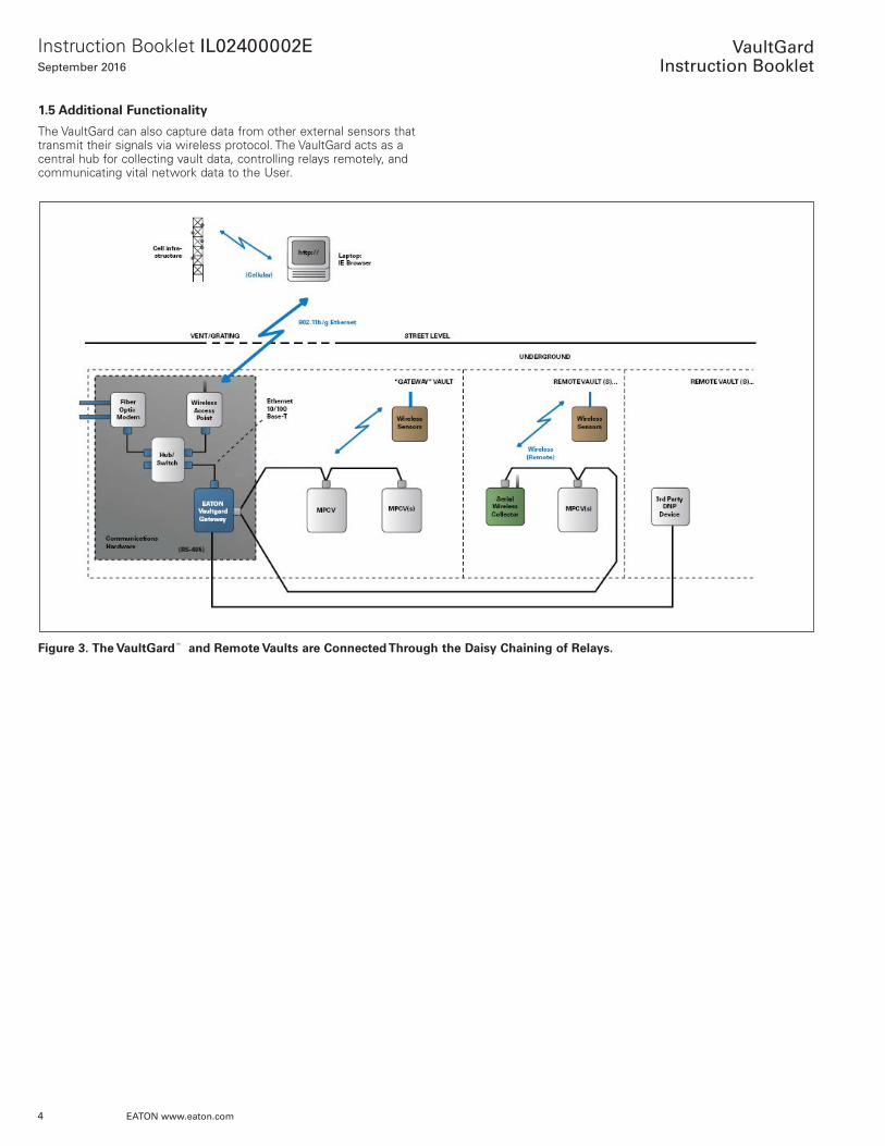
The VaultGard can also capture data from other external sensors that transmit their signals via wireless protocol . The VaultGard acts as a central hub for collecting vault data, controlling relays remotely, and communicating vital network data to the User .
Figure 3. The VaultGardE and Remote Vaults are Connected Through the Daisy Chaining of Relays.
5
Instruction Booklet IL02400002ESeptember 2016
EATON www.eaton.com
VaultGard
Instruction Booklet
Section 2. Features, Functions, Benefits, and Specifications2.1 Features
• Next generation communications product for Network Protectors;• Connect up to 32 MPCV devices on 1 unit;• Easy to navigate, on-board web pages (no software needed);• Comprehensive data monitoring (voltage, current, power metrics,
etc .);• Compatible with the optional Power Xpert software application to
integrate entire network of VaultGard Units; and• Compatible with wireless current sensors for vital cable loading
data .
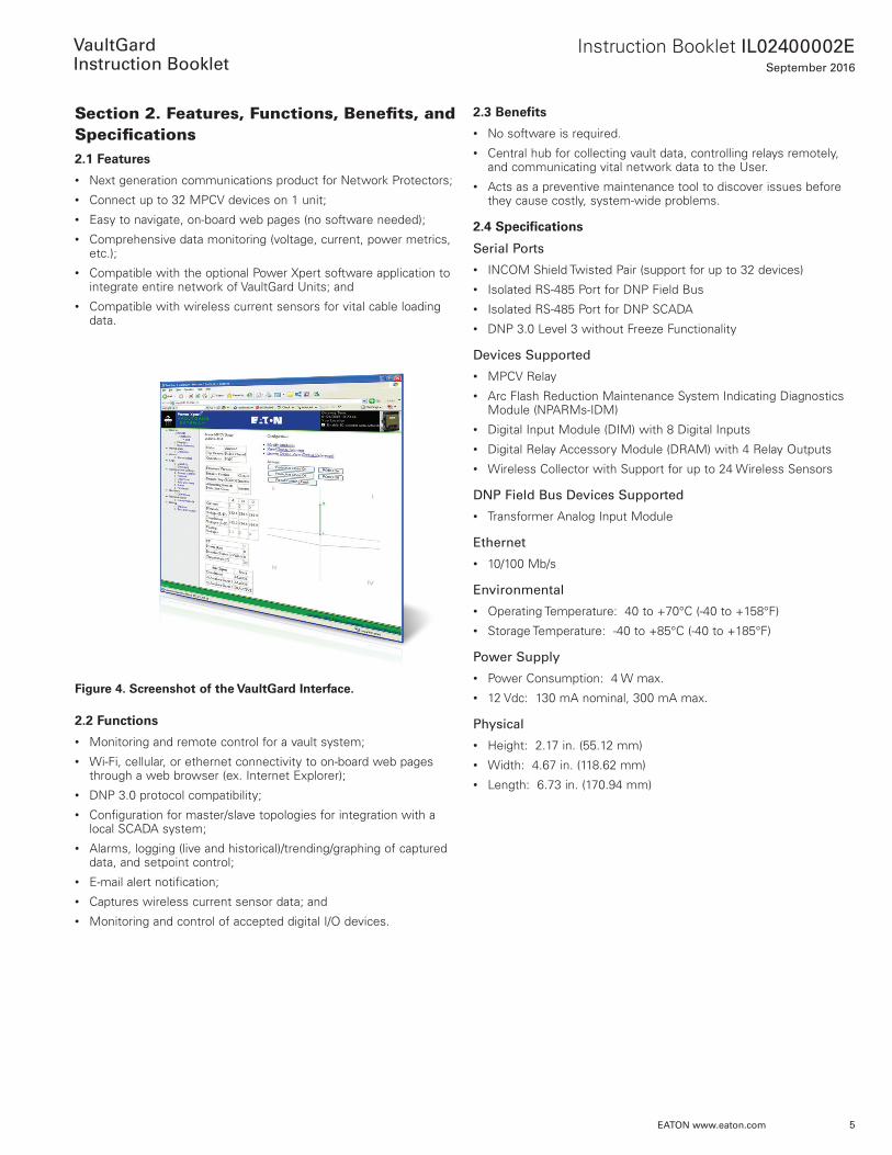
Figure 4. Screenshot of the VaultGard Interface.
2.2 Functions
• Monitoring and remote control for a vault system;• Wi-Fi, cellular, or ethernet connectivity to on-board web pages
through a web browser (ex . Internet Explorer);• DNP 3 .0 protocol compatibility;• Configuration for master/slave topologies for integration with a
local SCADA system;• Alarms, logging (live and historical)/trending/graphing of captured
data, and setpoint control;• E-mail alert notification;• Captures wireless current sensor data; and• Monitoring and control of accepted digital I/O devices .
2.3 Benefits
• No software is required .• Central hub for collecting vault data, controlling relays remotely,
and communicating vital network data to the User .• Acts as a preventive maintenance tool to discover issues before
they cause costly, system-wide problems .
2.4 Specifications
Serial Ports
• INCOM Shield Twisted Pair (support for up to 32 devices)• Isolated RS-485 Port for DNP Field Bus• Isolated RS-485 Port for DNP SCADA• DNP 3 .0 Level 3 without Freeze Functionality
Devices Supported
• MPCV Relay• Arc Flash Reduction Maintenance System Indicating Diagnostics
Module (NPARMs-IDM)• Digital Input Module (DIM) with 8 Digital Inputs• Digital Relay Accessory Module (DRAM) with 4 Relay Outputs• Wireless Collector with Support for up to 24 Wireless Sensors
DNP Field Bus Devices Supported
• Transformer Analog Input Module
Ethernet
• 10/100 Mb/s
Environmental
• Operating Temperature: 40 to +70°C (-40 to +158°F)• Storage Temperature: -40 to +85°C (-40 to +185°F)
Power Supply
• Power Consumption: 4 W max .• 12 Vdc: 130 mA nominal, 300 mA max .
Physical
• Height: 2 .17 in . (55 .12 mm)• Width: 4 .67 in . (118 .62 mm)• Length: 6 .73 in . (170 .94 mm)
6
Instruction Booklet IL02400002ESeptember 2016
EATON www.eaton.com
VaultGard
Instruction Booklet
Section 3: VaultGard Functional Overview3.1 Data View
The Data View section allows the User to access six different views:
• System View;
• Feeders;
• Protectors;
• Vaults;
• Spot Network View; and
• System Status View .
Each of the views displays information about the devices (i .e ., MPCV relays, Transformer Analog Input Monitors, DIM, DRAM, NP ARMs, Wireless Sensors, etc .) connected to VaultGard .
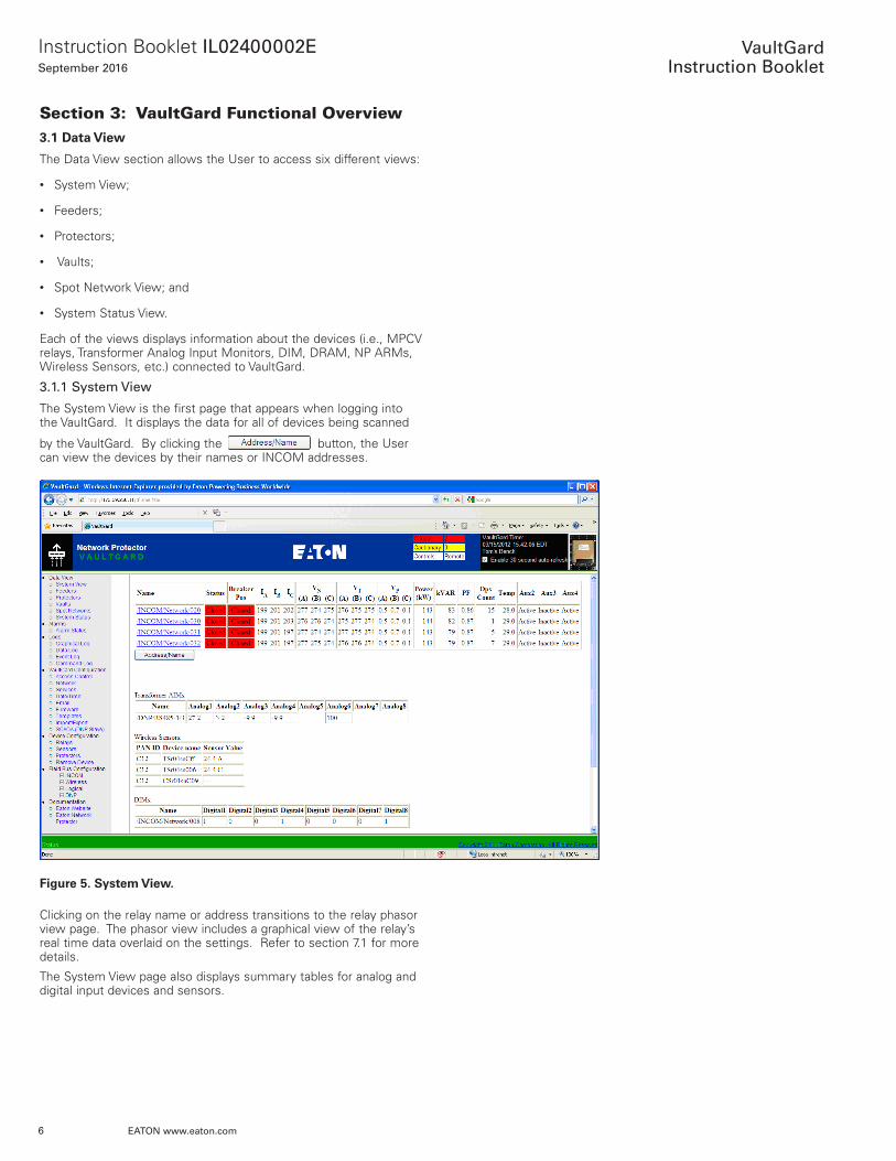
3.1.1 System View
The System View is the first page that appears when logging into the VaultGard . It displays the data for all of devices being scanned
by the VaultGard . By clicking the button, the User can view the devices by their names or INCOM addresses .
Figure 5. System View.
Clicking on the relay name or address transitions to the relay phasor view page . The phasor view includes a graphical view of the relay’s real time data overlaid on the settings . Refer to section 7 .1 for more details .
The System View page also displays summary tables for analog and digital input devices and sensors .
7
Instruction Booklet IL02400002ESeptember 2016
EATON www.eaton.com
VaultGard
Instruction Booklet
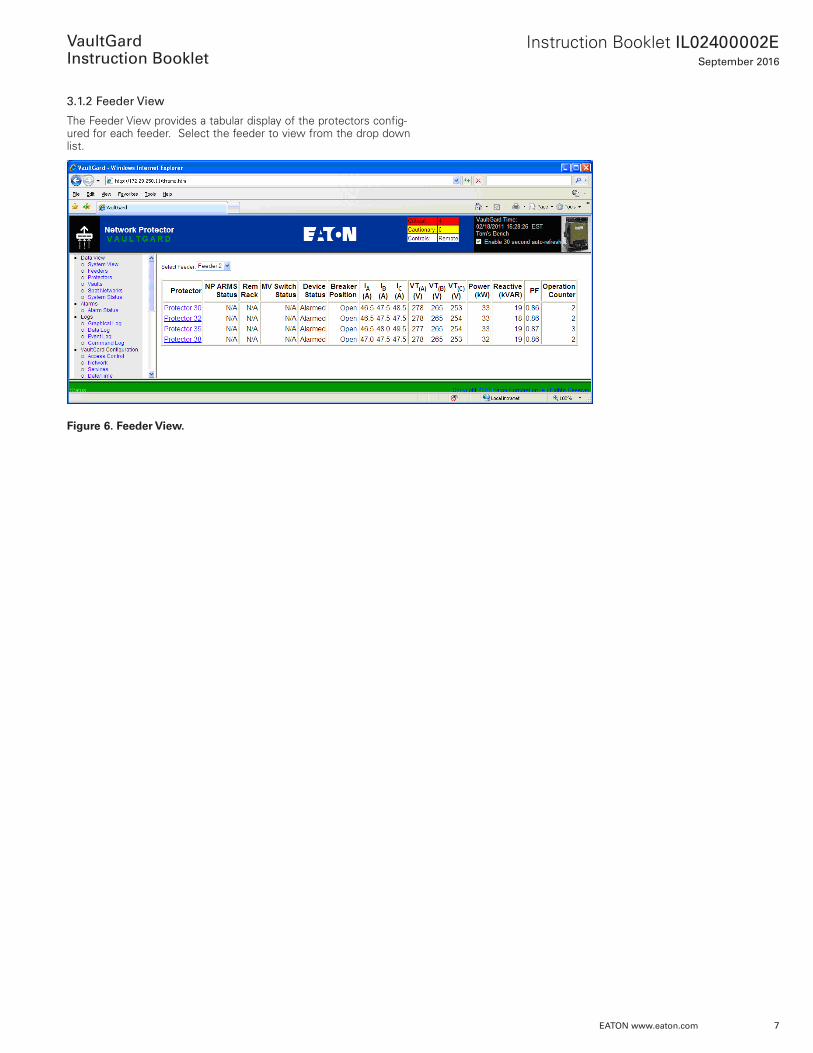
3.1.2 Feeder View
The Feeder View provides a tabular display of the protectors config-ured for each feeder . Select the feeder to view from the drop down list .
Figure 6. Feeder View.
8
Instruction Booklet IL02400002ESeptember 2016
EATON www.eaton.com
VaultGard
Instruction Booklet
3.1.3 Protector View
The Protector View displays a table showing summary data for all the protectors being scanned by VaultGard . This feature will need to be set up before any information or data can be displayed on the page . Refer to Section 7 .3 for the initial set up .
Figure 7. Protector View.
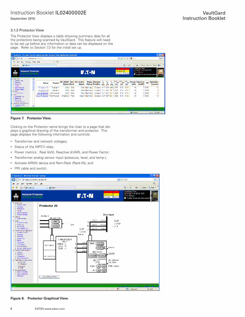
Clicking on the Protector name brings the User to a page that dis-plays a graphical drawing of the transformer and protector . This page displays the following information and controls:
• Transformer and network voltages;• Status of the MPCV relay;• Power metrics: Real (kW), Reactive (kVAR), and Power Factor;• Transformer analog sensor input (pressure, level, and temp .);• Activate ARMS device and Rem-Rack (Rack-IN); and• PRI cable and switch .
Figure 8. Protector Graphical View.
9
Instruction Booklet IL02400002ESeptember 2016
EATON www.eaton.com
VaultGard
Instruction Booklet
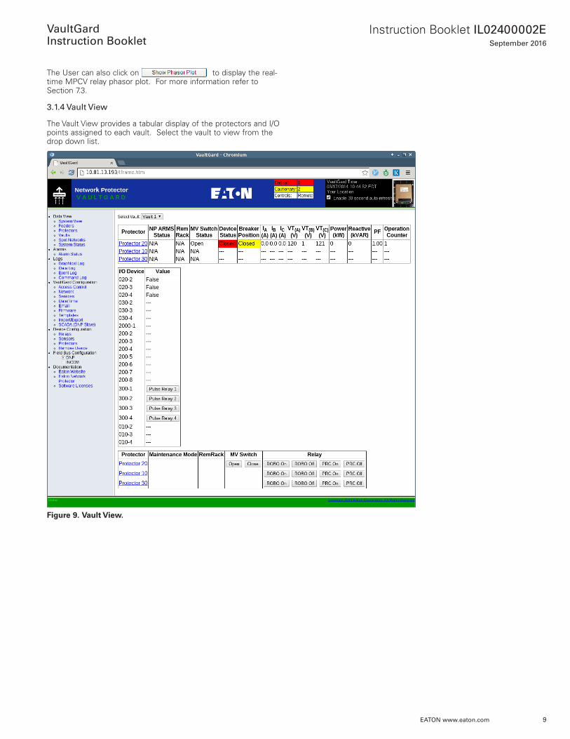
The User can also click on to display the real-time MPCV relay phasor plot . For more information refer to Section 7 .3 .
3.1.4 Vault View
The Vault View provides a tabular display of the protectors and I/O points assigned to each vault . Select the vault to view from the drop down list .
Figure 9. Vault View.
10
Instruction Booklet IL02400002ESeptember 2016
EATON www.eaton.com
VaultGard
Instruction Booklet
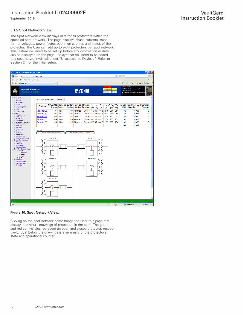
3.1.5 Spot Network View
The Spot Network View displays data for all protectors within the specified spot network . The page displays phase currents, trans-former voltages, power factor, operation counter, and status of the protector . The User can add up to eight protectors per spot network . This feature will need to be set up before any information or data can be displayed on the page . Relays that still need to be added to a spot network will fall under “Unassociated Devices” . Refer to Section 7 .4 for the initial setup .
Figure 10. Spot Network View.
Clicking on the spot network name brings the User to a page that displays the virtual drawings of protectors in the spot . The green and red semi-circles represent an open and closed protector, respec-tively . Just below the drawings is a summary of the protector’s state and operational counter .
11
Instruction Booklet IL02400002ESeptember 2016
EATON www.eaton.com
VaultGard
Instruction Booklet
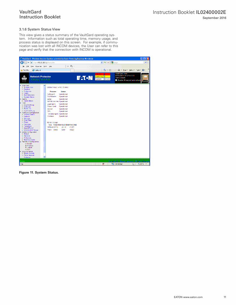
3.1.6 System Status View
This view gives a status summary of the VaultGard operating sys-tem . Information such as total operating time, memory usage, and process status is displayed on this screen . For example, if commu-nication was lost with all INCOM devices, the User can refer to this page and verify that the connection with INCOM is operational .
Figure 11. System Status.

12
Instruction Booklet IL02400002ESeptember 2016
EATON www.eaton.com
VaultGard
Instruction Booklet
Section 4: AlarmsAn alarm occurs when a parameter value reaches an alarm limit . An e-mail will be sent to the predefined addresses for devices that have been configured for alarms and e-mail . Alarms are supported for MPCV relays, sensors, and protectors . Refer to section 7 .1 .4 for detailed instructions to configure a device for alarming .
4.1 Alarm Status
Clicking on Alarm Status will display a page with a list of the alarms that have occurred, the condition of each alarm, and all devices that are currently alarmed .
VaultGard displays alarms communicated from individual devices or generated in VaultGard based on a data value excursion beyond the limits set in the Alarm Configuration .
Figure 12. Alarm Status.
Alarms can be individually acknowledged and closed using the but-tons in the table, or all alarms can be closed using the <Close All Alarms> button .
The alarm display in the top banner can be configured to flash when a new alarm notification is present . Click the <Enable Alarm Flash> button when the critical and cautionary alarm counts are 0 to enable alarm flashing .
The <Refresh Alarms> button is provided to update the Alarm Status web page, because the Alarm page does not auto-refresh . This is to limit network communication traffic for slow networks (i .e . cellular) .
The Alarm Status can be saved to a file using the <Save List to CSV> button .
13
Instruction Booklet IL02400002ESeptember 2016
EATON www.eaton.com
VaultGard
Instruction Booklet
Section 5: LogsThe VaultGard contains four different logging views:
• Graphical;• Data;• Event; and• Command .
Before the VaultGard can begin logging values, each device will need to be set up for logging . Refer to Section 7 .1 .4 for further details .
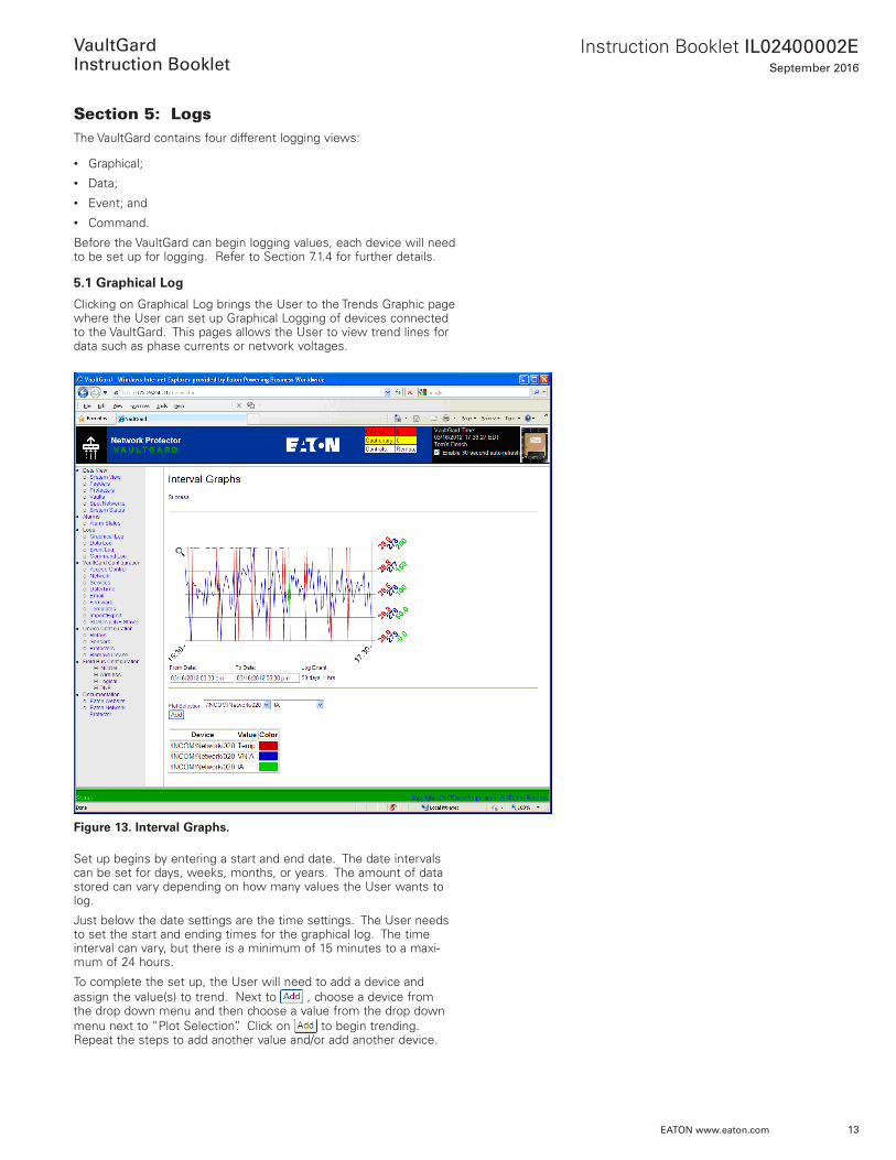
5.1 Graphical Log
Clicking on Graphical Log brings the User to the Trends Graphic page where the User can set up Graphical Logging of devices connected to the VaultGard . This pages allows the User to view trend lines for data such as phase currents or network voltages .
Figure 13. Interval Graphs.
Set up begins by entering a start and end date . The date intervals can be set for days, weeks, months, or years . The amount of data stored can vary depending on how many values the User wants to log .
Just below the date settings are the time settings . The User needs to set the start and ending times for the graphical log . The time interval can vary, but there is a minimum of 15 minutes to a maxi-mum of 24 hours .
To complete the set up, the User will need to add a device and assign the value(s) to trend . Next to , choose a device from the drop down menu and then choose a value from the drop down menu next to “Plot Selection” . Click on to begin trending . Repeat the steps to add another value and/or add another device .
14
Instruction Booklet IL02400002ESeptember 2016
EATON www.eaton.com
VaultGard
Instruction Booklet
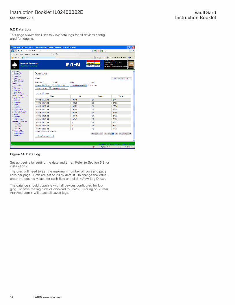
5.2 Data Log
This page allows the User to view data logs for all devices config-ured for logging .
Figure 14. Data Log.
Set up begins by setting the date and time . Refer to Section 6 .3 for instructions .
The user will need to set the maximum number of rows and page links per page . Both are set to 20 by default . To change the value, enter the desired values for each field and click <View Log Data> .
The data log should populate with all devices configured for log-ging . To save the log click <Download to CSV> . Clicking on <Clear Archived Logs> will erase all saved logs .
15
Instruction Booklet IL02400002ESeptember 2016
EATON www.eaton.com
VaultGard
Instruction Booklet
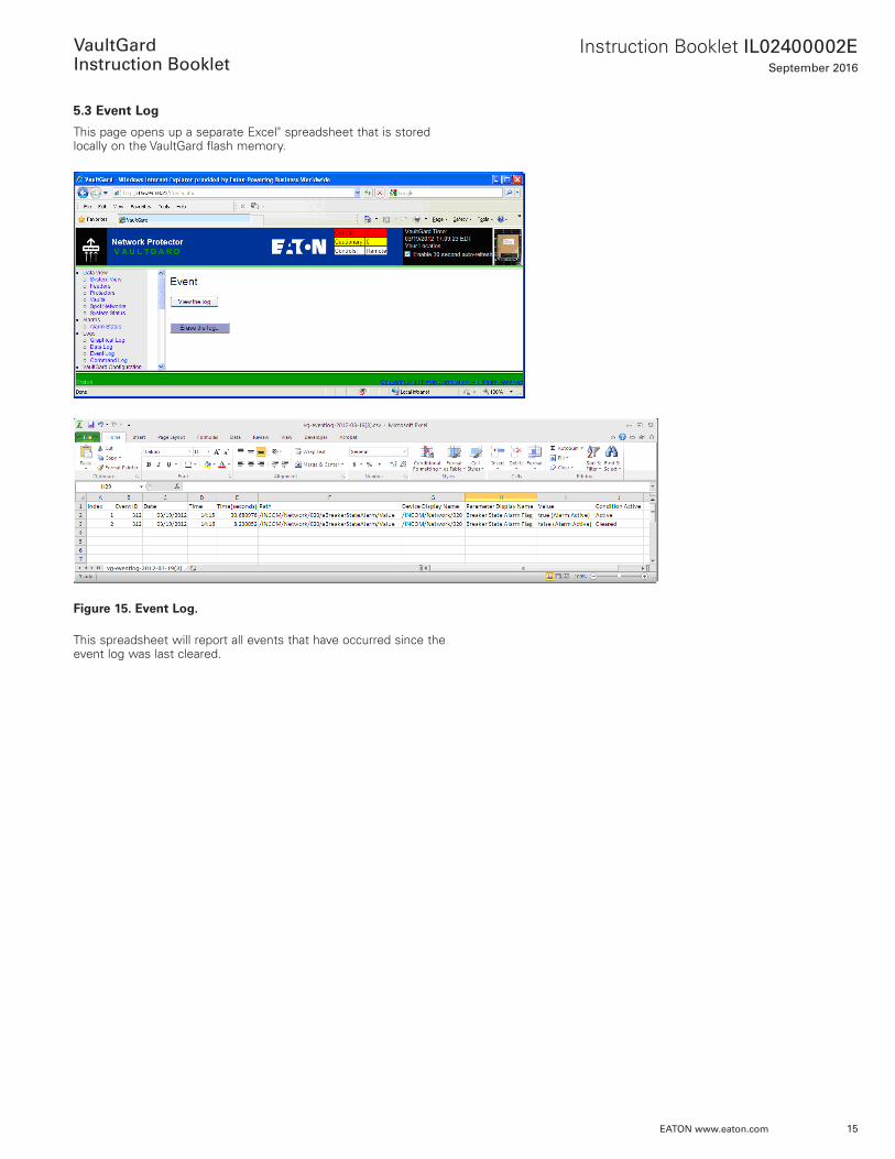
5.3 Event Log
This page opens up a separate ExcelT spreadsheet that is stored locally on the VaultGard flash memory .
Figure 15. Event Log.
This spreadsheet will report all events that have occurred since the event log was last cleared .

16
Instruction Booklet IL02400002ESeptember 2016
EATON www.eaton.com
VaultGard
Instruction Booklet
5.4 Command Log
This page displays active, terminated, and denied commands that have been executed since the VaultGard was powered up .
The Command Log records a history of the configuration and control commands executed on VaultGard . Each entry records the issuer (user), command, time, and status of the command . This log can be saved to a CSV file .
Figure 16. Command Log.
The user can view the type of command initiated, who initiated the command, the result, start and end times of the command, the state, and the parameters .
The VaultGard boot history may be viewed by navigating to the Bootup History tab of the Logs → Command Log
Figure 17. Bootup History Tab.
17
Instruction Booklet IL02400002ESeptember 2016
EATON www.eaton.com
VaultGard
Instruction Booklet
Section 6: VaultGard Set-Up and Configuration6.1 Access Control
The Customer can configure the VaultGard to allow different levels of security for different users . When the Customer first logs into the VaultGard, they are referred to as the “Superuser” . The “Superuser” has the ability to edit/delete user names, update the VaultGard firm-ware, and reset the VaultGard to factory settings . Another level of security is the “Administrator” . The “Administrator” can view and control the relays/devices on the VaultGard, but cannot update the firmware, reset to factory defaults, or create/delete usernames and passwords . The last level of security is the “User” . The “User” can only view the data on the VaultGard . All other functions are disabled at this level .
To begin configuration, follow the instructions below .
6.1.1 Configuration Names and Passwords
The VaultGard provides three different levels of security for login password access (Admin, User, and Superuser) .
• The “User” can view all data, but cannot perform device configu-ration, alarming, and logging .
• The “Admin” can change setpoints, perform device configuration, control, alarming, and logging .
• Only the “Superuser” can upload firmware or reset to factory configuration, which are both done on the Firmware web page . In addition, the “Superuser” is the only person who can set up User and Administrator names and passwords on the VaultGard Access Control web page .
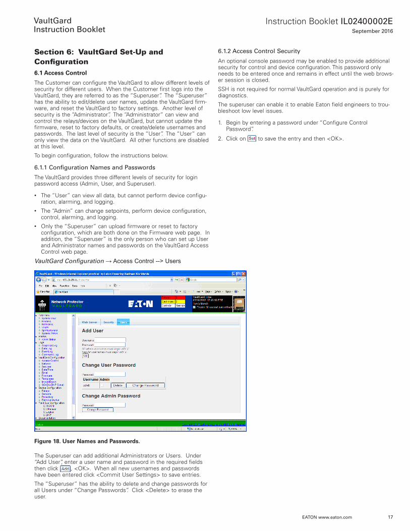
VaultGard Configuration → Access Control --> Users
Figure 18. User Names and Passwords.
The Superuser can add additional Administrators or Users . Under “Add User”, enter a user name and password in the required fields then click , <OK> . When all new usernames and passwords have been entered click <Commit User Settings> to save entries .
The “Superuser” has the ability to delete and change passwords for all Users under “Change Passwords” . Click <Delete> to erase the user .
6.1.2 Access Control Security
An optional console password may be enabled to provide additional security for control and device configuration . This password only needs to be entered once and remains in effect until the web brows-er session is closed .
SSH is not required for normal VaultGard operation and is purely for diagnostics .
The superuser can enable it to enable Eaton field engineers to trou-bleshoot low level issues .
1 . Begin by entering a password under “Configure Control Password” .
2 . Click on to save the entry and then <OK> .
18
Instruction Booklet IL02400002ESeptember 2016
EATON www.eaton.com
VaultGard
Instruction Booklet
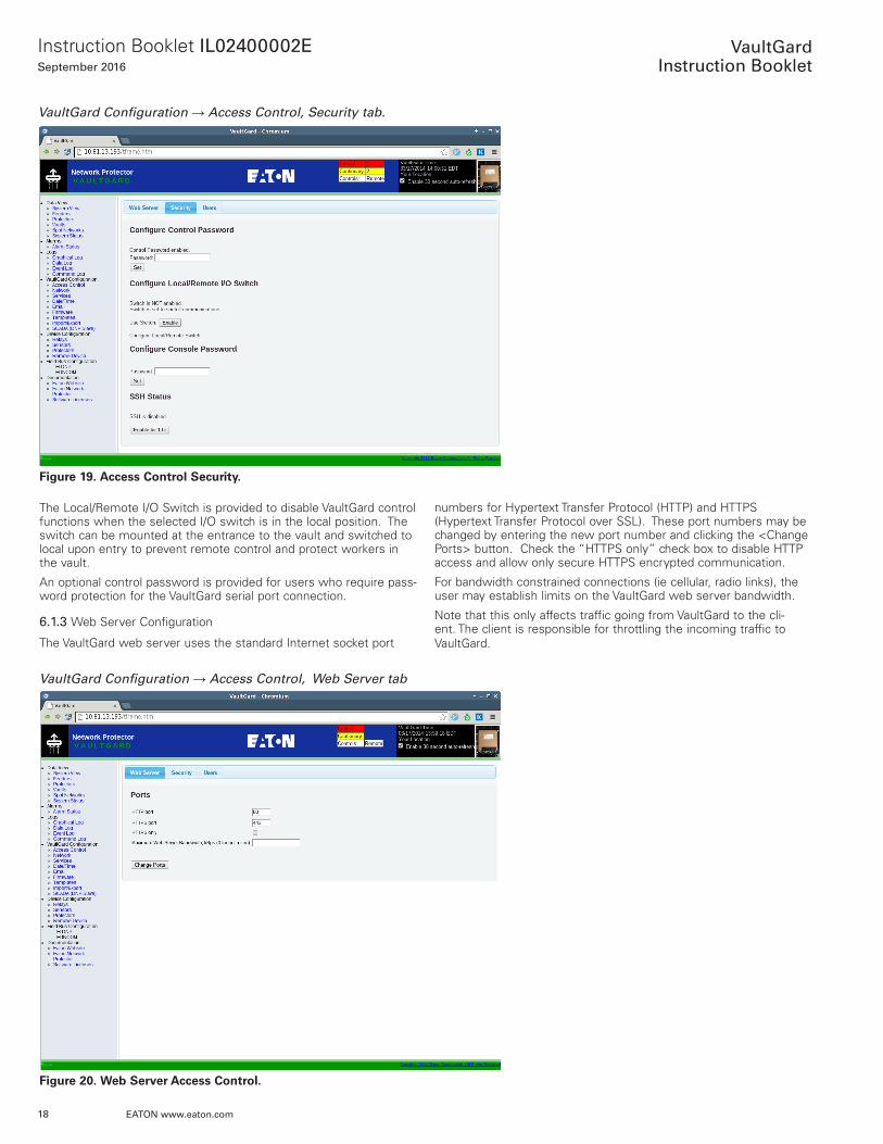
VaultGard Configuration → Access Control, Security tab.
Figure 19. Access Control Security.
The Local/Remote I/O Switch is provided to disable VaultGard control functions when the selected I/O switch is in the local position . The switch can be mounted at the entrance to the vault and switched to local upon entry to prevent remote control and protect workers in the vault .
An optional control password is provided for users who require pass-word protection for the VaultGard serial port connection .
6.1.3 Web Server Configuration
The VaultGard web server uses the standard Internet socket port
VaultGard Configuration → Access Control, Web Server tab
Figure 20. Web Server Access Control.
numbers for Hypertext Transfer Protocol (HTTP) and HTTPS (Hypertext Transfer Protocol over SSL) . These port numbers may be changed by entering the new port number and clicking the <Change Ports> button . Check the “HTTPS only” check box to disable HTTP access and allow only secure HTTPS encrypted communication .
For bandwidth constrained connections (ie cellular, radio links), the user may establish limits on the VaultGard web server bandwidth .
Note that this only affects traffic going from VaultGard to the cli-ent . The client is responsible for throttling the incoming traffic to VaultGard .
19
Instruction Booklet IL02400002ESeptember 2016
EATON www.eaton.com
VaultGard
Instruction Booklet
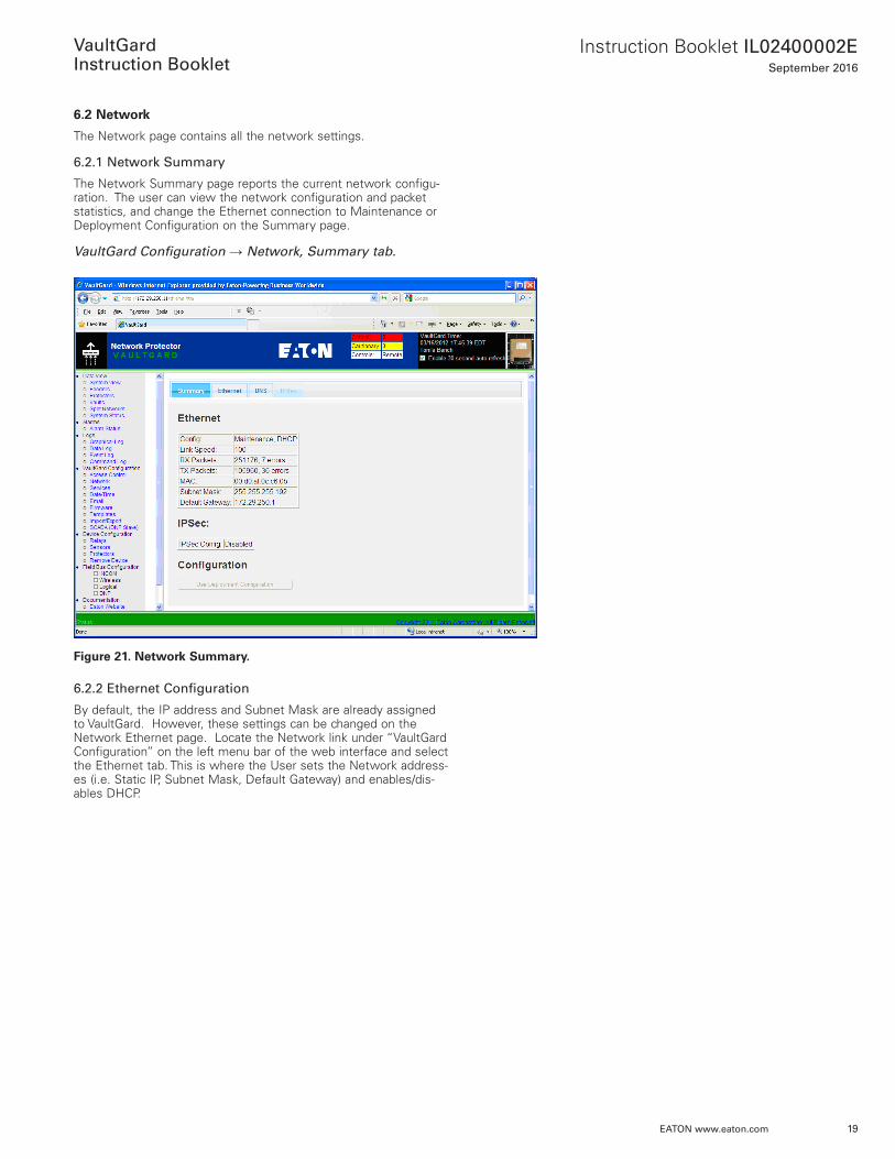
6.2 Network
The Network page contains all the network settings .
6.2.1 Network Summary
The Network Summary page reports the current network configu-ration . The user can view the network configuration and packet statistics, and change the Ethernet connection to Maintenance or Deployment Configuration on the Summary page .
VaultGard Configuration → Network, Summary tab.
Figure 21. Network Summary.
6.2.2 Ethernet Configuration
By default, the IP address and Subnet Mask are already assigned to VaultGard . However, these settings can be changed on the Network Ethernet page . Locate the Network link under “VaultGard Configuration” on the left menu bar of the web interface and select the Ethernet tab . This is where the User sets the Network address-es (i .e . Static IP, Subnet Mask, Default Gateway) and enables/dis-ables DHCP .

20
Instruction Booklet IL02400002ESeptember 2016
EATON www.eaton.com
VaultGard
Instruction Booklet
VaultGard Configuration → Network, Ethernet Tab
Figure 22. Ethernet Configuration.
VaultGard provides separate Ethernet settings for Maintenance and Deployment configurations . If a single configuration is adequate just use the Maintenance configuration . It can be changed via the local VaultGard serial port or by navigating to the Ethernet Network web page .
The Deployment configuration is provided for installations where a one IP address is required for the network configuration (Deployment) and a separate IP address is used for local Ethernet connection (Maintenance) . The Deployment configuration can only be configured using the Ethernet Network web page . Only the Deployment configuration can be used with IPSec .
If the network connection requires a gratuitous ARP, the ARP packet count on startup can be entered for either configuration .
The MTU (maximum transmission unit) can also be set here . The default MTU value is 1500 . The superuser may reduce the MTU to eliminate fragmentation issues over link technologies support small-er packet sizes or when using IPSec .
The TCP Congestion Control Algorithm optimizes VaultGard’s upstream bandwidth usage by automatically scaling sending speeds to link conditions and bandwidth maximums . The choice of an algo-rithm depends on the properties of the link to VaultGard, bandwidth considerations, as well as the algorithms of other devices on the network . A full description of these algorithms is outside the scope of this manual, but the following are some general guidelines . These guidelines are not to be taken as absolute advice; please contact your network administrator for further support .• Cubic: Good default for pure ethernet or fiber connections .• Illinois: May work better on fiber connections .
• Reno: Attempts to avoid congestion, may improve performance on radio or other lossy networks .
• Vegas: Detects congestion by measuring packet delay times . May improve performance on lossy networks .
• Veno: Better performance in networks prone to bit errors .• Westwood: Use on lossy or crowded fiber connections .• YeAH: Another RTT sensing algorithm that strives for efficiency .
The Connectivity Log records when VaultGard’s ethernet connection is unplugged or plugged, or loses carrier to its Ethernet link partner . This is useful for troubleshooting disconnect issues or for checking when the Ethernet plug is disconnected for maintenance .
To change the static IP address enter the new IP Address, Subnet Mask, and Default Gateway and click the <Use Static Config> button . Alternately, click the <Use DHCP> button to enable the Dynamic Host Configuration Protocol (DHCP) .
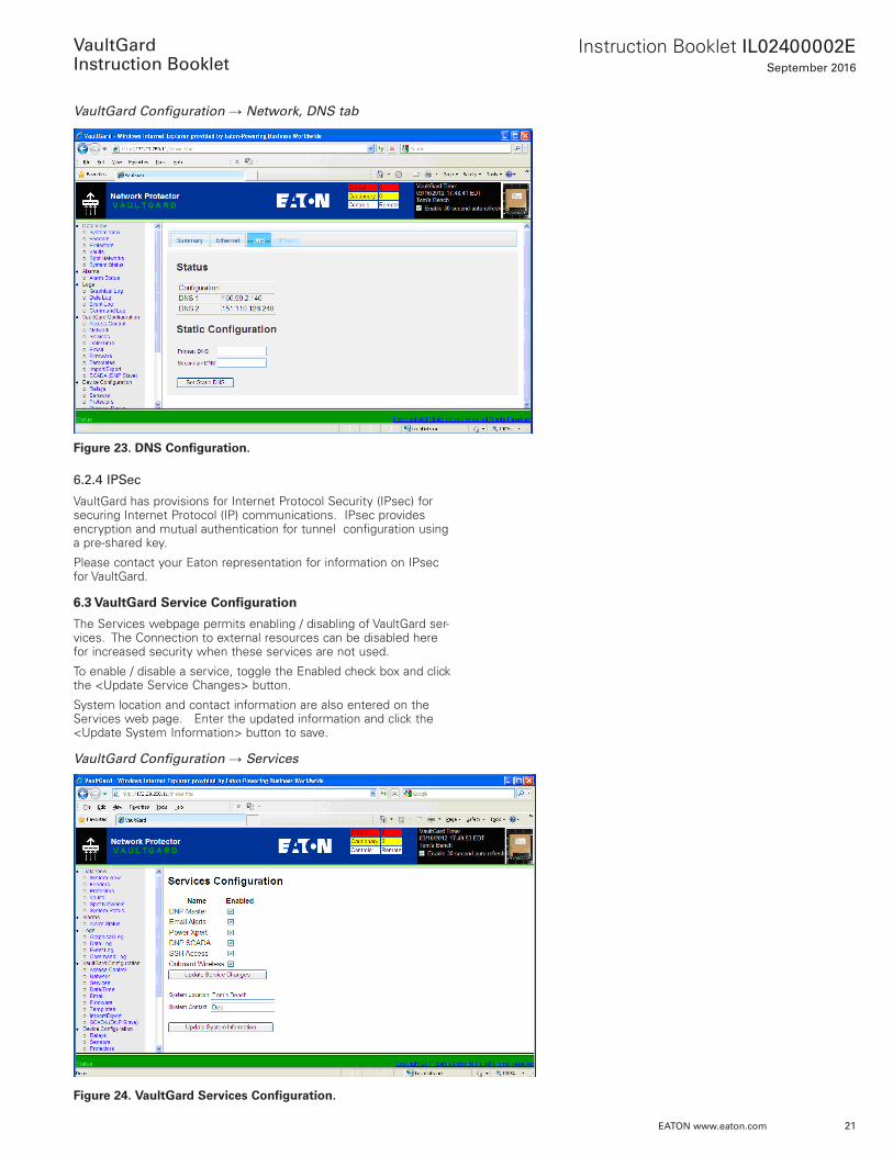
6.2.3 DNS Configuration
Locate the Network link under “VaultGard Configuration” on the left menu bar of the web interface and select the DNS tab . Primary and Secondary Domain Name System (DNS) Server IP addresses may be entered and saved by clicking the <Set Static DNS> button .
A DNS server converts a human readable name into an Internet Protocol (IP) address, and is not required if all network references use IP addresses . However, a DNS server IP address is needed if you enter an SMTP server name for e-mail notifications .
21
Instruction Booklet IL02400002ESeptember 2016
EATON www.eaton.com
VaultGard
Instruction Booklet
VaultGard Configuration → Network, DNS tab
Figure 23. DNS Configuration.
6.2.4 IPSec
VaultGard has provisions for Internet Protocol Security (IPsec) for securing Internet Protocol (IP) communications . IPsec provides encryption and mutual authentication for tunnel configuration using a pre-shared key .
Please contact your Eaton representation for information on IPsec for VaultGard .
6.3 VaultGard Service Configuration
The Services webpage permits enabling / disabling of VaultGard ser-vices . The Connection to external resources can be disabled here for increased security when these services are not used .
To enable / disable a service, toggle the Enabled check box and click the <Update Service Changes> button .
System location and contact information are also entered on the Services web page . Enter the updated information and click the <Update System Information> button to save .
VaultGard Configuration → Services
Figure 24. VaultGard Services Configuration.

22
Instruction Booklet IL02400002ESeptember 2016
EATON www.eaton.com
VaultGard
Instruction Booklet
6.4 Configuration Date/Time
The date and time for the VaultGard is located at the top right hand corner of the web server .
Select VaultGard Configuration → Date/Time to configure the VaultGard clock.
Figure 25. Date and Time Status.
Click the Locale tab and select the proper time zone from the drop-down list .
Figure 26. Time Zone Selection.
Click <Apply Settings> for the selected Time Zone to take effect .
23
Instruction Booklet IL02400002ESeptember 2016
EATON www.eaton.com
VaultGard
Instruction Booklet
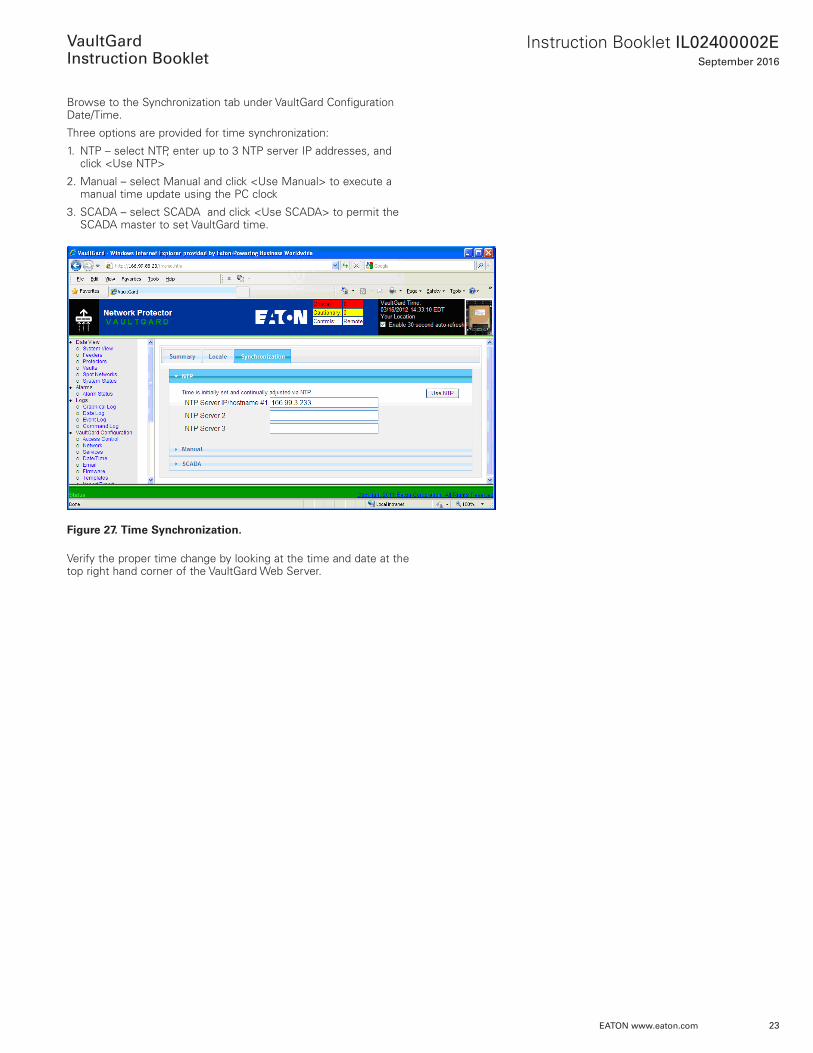
Browse to the Synchronization tab under VaultGard Configuration Date/Time .
Three options are provided for time synchronization:
1 . NTP – select NTP, enter up to 3 NTP server IP addresses, and click <Use NTP>
2 . Manual – select Manual and click <Use Manual> to execute a manual time update using the PC clock
3 . SCADA – select SCADA and click <Use SCADA> to permit the SCADA master to set VaultGard time .
Figure 27. Time Synchronization.
Verify the proper time change by looking at the time and date at the top right hand corner of the VaultGard Web Server .
24
Instruction Booklet IL02400002ESeptember 2016
EATON www.eaton.com
VaultGard
Instruction Booklet
6.5 E-mail Configuration
VaultGard has the ability to send an email when it detects a native device event or a user-defined event . Each device can be configured to send information / values to a number of people on the mailing list . However, before an e-mail will be sent, devices must be config-ured for alarming . The use of alarm and e-mail templates simplifies the process of copying a desired configuration to multiple devices .
To begin e-mail configuration, follow the instructions below . Locate the Email link under “VaultGard Configuration” on the left menu bar of the web interface . This is where the User configures the mail server, sets e-mail alerts for individual devices and adds e-mail addresses to receive alerts .
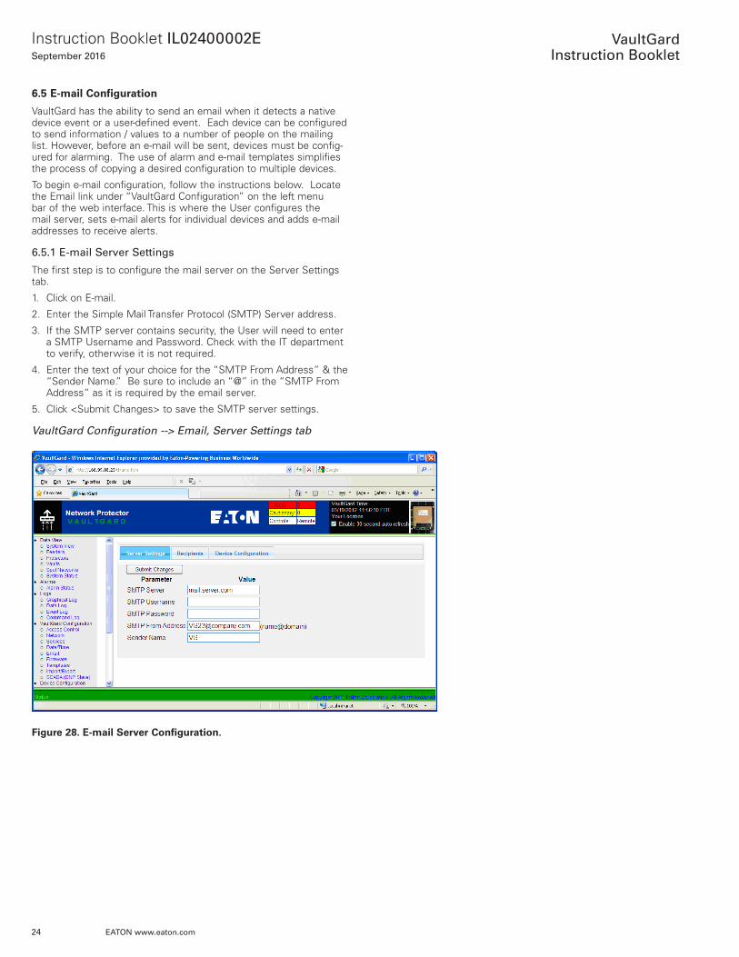
6.5.1 E-mail Server Settings
The first step is to configure the mail server on the Server Settings tab .
1 . Click on E-mail .
2 . Enter the Simple Mail Transfer Protocol (SMTP) Server address .
3 . If the SMTP server contains security, the User will need to enter a SMTP Username and Password . Check with the IT department to verify, otherwise it is not required .
4 . Enter the text of your choice for the “SMTP From Address” & the “Sender Name .” Be sure to include an “@” in the “SMTP From Address” as it is required by the email server .
5 . Click <Submit Changes> to save the SMTP server settings .
VaultGard Configuration --> Email, Server Settings tab
Figure 28. E-mail Server Configuration.
25
Instruction Booklet IL02400002ESeptember 2016
EATON www.eaton.com
VaultGard
Instruction Booklet
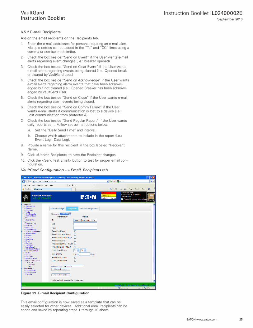
6.5.2 E-mail Recipients
Assign the email recipients on the Recipients tab .
1 . Enter the e-mail addresses for persons requiring an e-mail alert . Multiple entries can be added in the “To” and “CC” lines using a comma or semicolon delimiter .
2 . Check the box beside “Send on Event” if the User wants e-mail alerts regarding event changes (i .e .: breaker opened) .
3 . Check the box beside “Send on Clear Event” if the User wants e-mail alerts regarding events being cleared (i .e .: Opened break-er cleared by VaultGard user .)
4 . Check the box beside “Send on Acknowledge” if the User wants e-mail alerts regarding alarm events that have been acknowl-edged but not cleared (i .e .: Opened Breaker has been acknowl-edged by VaultGard User
5 . Check the box beside “Send on Close” if the User wants e-mail alerts regarding alarm events being closed .
6 . Check the box beside “Send on Comm Failure” if the User wants e-mail alerts if communication is lost to a device (i .e .: Lost communication from protector A) .
7 . Check the box beside “Send Regular Report” if the User wants daily reports sent . Follow set up instructions below .
a . Set the “Daily Send Time” and interval .
b . Choose which attachments to include in the report (i .e .: Event Log, Data Log) .
8 . Provide a name for this recipient in the box labeled “Recipient Name” .
9 . Click <Update Recipient> to save the Recipient changes .
10 . Click the <Send Test Email> button to test for proper email con-figuration .
VaultGard Configuration --> Email, Recipients tab
Figure 29. E-mail Recipient Configuration.
This email configuration is now saved as a template that can be easily selected for other devices . Additional email recipients can be added and saved by repeating steps 1 through 10 above .
26
Instruction Booklet IL02400002ESeptember 2016
EATON www.eaton.com
VaultGard
Instruction Booklet
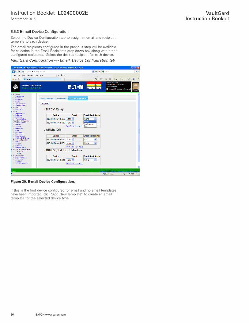
6.5.3 E-mail Device Configuration
Select the Device Configuration tab to assign an email and recipient template to each device .
The email recipients configured in the previous step will be available for selection in the Email Recipients drop-down box along with other configured recipients . Select the desired recipient for each device .
VaultGard Configuration --> Email, Device Configuration tab
Figure 30. E-mail Device Configuration.
If this is the first device configured for email and no email templates have been imported, click “Add New Template” to create an email template for the selected device type .
27
Instruction Booklet IL02400002ESeptember 2016
EATON www.eaton.com
VaultGard
Instruction Booklet
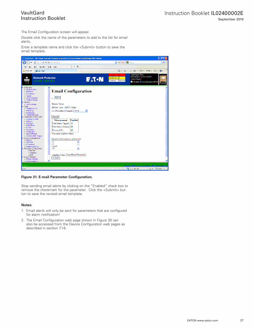
The Email Configuration screen will appear .
Double click the name of the parameters to add to the list for email alerts .
Enter a template name and click the <Submit> button to save the email template .
Figure 31. E-mail Parameter Configuration.
Stop sending email alerts by clicking on the “Enabled” check box to remove the checkmark for the parameter . Click the <Submit> but-ton to save the revised email template .
Notes:
1 . Email alerts will only be sent for parameters that are configured for alarm notification!
2 . The Email Configuration web page shown in Figure 30 can also be accessed from the Device Configuration web pages as described in section 7 .1 .6 .

28
Instruction Booklet IL02400002ESeptember 2016
EATON www.eaton.com
VaultGard
Instruction Booklet
6.6 Firmware
The VaultGard’s firmware will need to be updated every time a new firmware release is available . These updates are necessary to ensure that the latest features and graphics are installed on the VaultGard . The latest firmware will be available on the Eaton Network Protector Website under “Firmware Updates” (www .eaton .com/nwp) .
VaultGard Configuration → Firmware
The About tab shows the current firmware version, date, and update status . VaultGard diagnostic information can be saved to a file by clicking the <Download Diagnostic Information> button .
Figure 32. Firmware Status.
To upload new firmware select the Control tab and click <Upload Firmware>
Figure 33. .Firmware Update Page.
29
Instruction Booklet IL02400002ESeptember 2016
EATON www.eaton.com
VaultGard
Instruction Booklet
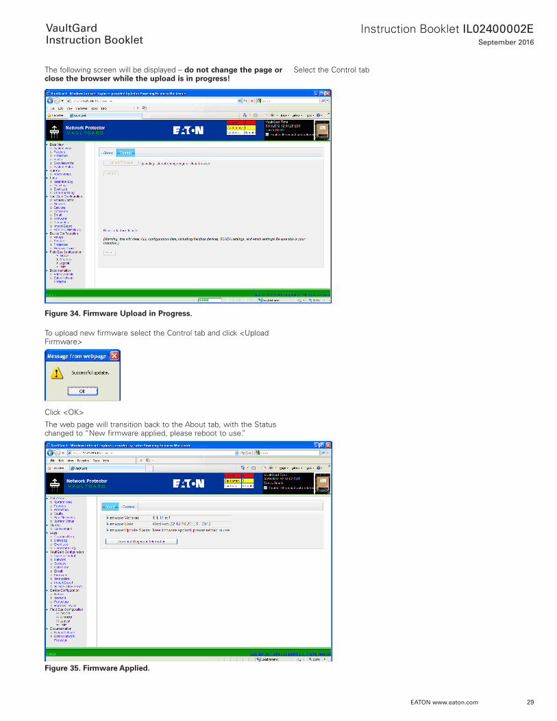
The following screen will be displayed – do not change the page or close the browser while the upload is in progress!
Figure 34. Firmware Upload in Progress.
To upload new firmware select the Control tab and click <Upload Firmware>
Click <OK>
The web page will transition back to the About tab, with the Status changed to “New firmware applied, please reboot to use .”
Figure 35. Firmware Applied.
Select the Control tab
30
Instruction Booklet IL02400002ESeptember 2016
EATON www.eaton.com
VaultGard
Instruction Booklet
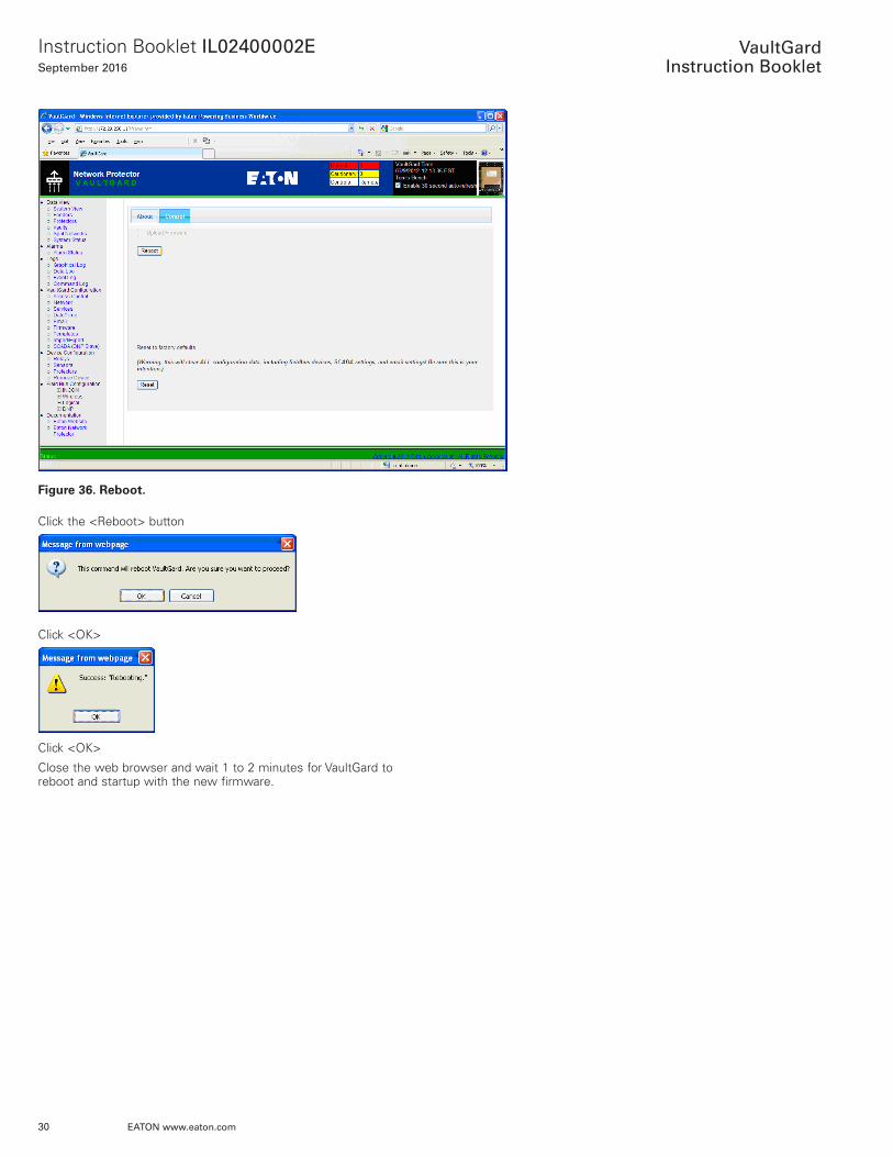
Figure 36. Reboot.
Click the <Reboot> button
Click <OK>
Click <OK>
Close the web browser and wait 1 to 2 minutes for VaultGard to reboot and startup with the new firmware .
31
Instruction Booklet IL02400002ESeptember 2016
EATON www.eaton.com
VaultGard
Instruction Booklet
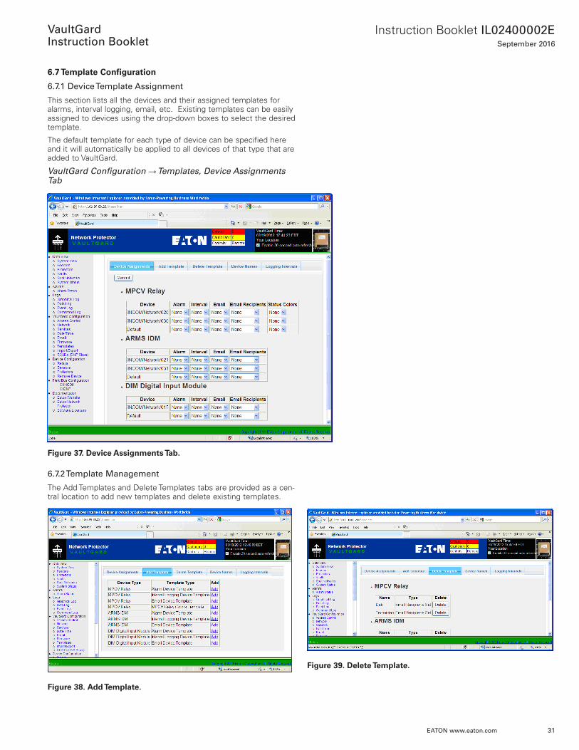
6.7 Template Configuration
6.7.1 Device Template Assignment
This section lists all the devices and their assigned templates for alarms, interval logging, email, etc . Existing templates can be easily assigned to devices using the drop-down boxes to select the desired template .
The default template for each type of device can be specified here and it will automatically be applied to all devices of that type that are added to VaultGard .
VaultGard Configuration → Templates, Device Assignments Tab
Figure 37. Device Assignments Tab.
6.7.2 Template Management
The Add Templates and Delete Templates tabs are provided as a cen-tral location to add new templates and delete existing templates .
Figure 38. Add Template.
Figure 39. Delete Template.
32
Instruction Booklet IL02400002ESeptember 2016
EATON www.eaton.com
VaultGard
Instruction Booklet
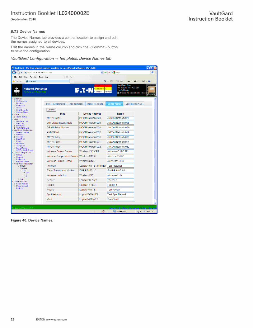
6.7.3 Device Names
The Device Names tab provides a central location to assign and edit the names assigned to all devices .
Edit the names in the Name column and click the <Commit> button to save the configuration .
VaultGard Configuration → Templates, Device Names tab
Figure 40. Device Names.
33
Instruction Booklet IL02400002ESeptember 2016
EATON www.eaton.com
VaultGard
Instruction Booklet
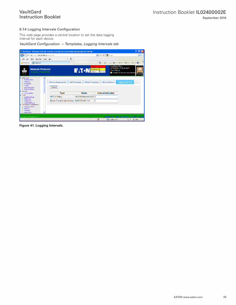
6.7.4 Logging Intervals Configuration
This web page provides a central location to set the data logging interval for each device .
VaultGard Configuration → Templates, Logging Intervals tab
Figure 41. Logging Intervals.
34
Instruction Booklet IL02400002ESeptember 2016
EATON www.eaton.com
VaultGard
Instruction Booklet
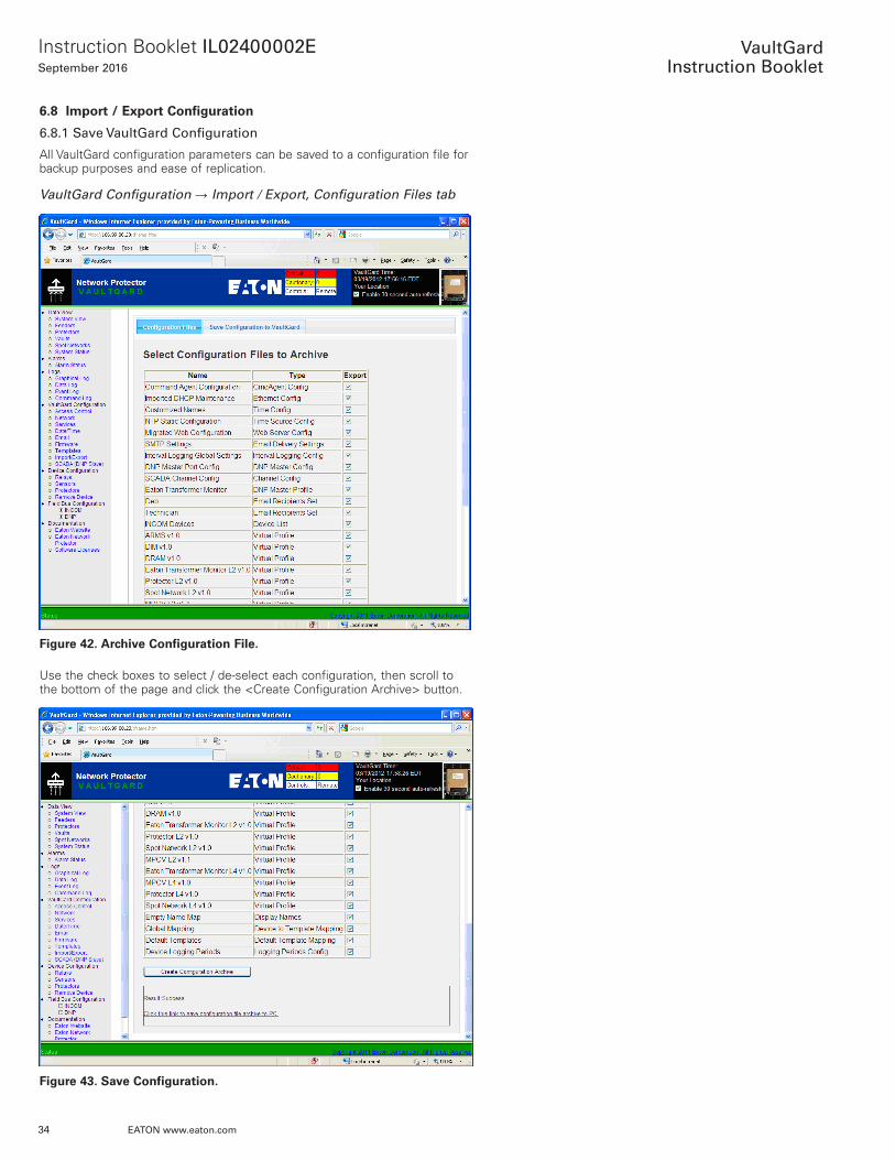
6.8 Import / Export Configuration
6.8.1 Save VaultGard Configuration
All VaultGard configuration parameters can be saved to a configuration file for backup purposes and ease of replication .
VaultGard Configuration → Import / Export, Configuration Files tab
Figure 42. Archive Configuration File.
Use the check boxes to select / de-select each configuration, then scroll to the bottom of the page and click the <Create Configuration Archive> button .
Figure 43. Save Configuration.
35
Instruction Booklet IL02400002ESeptember 2016
EATON www.eaton.com
VaultGard
Instruction Booklet
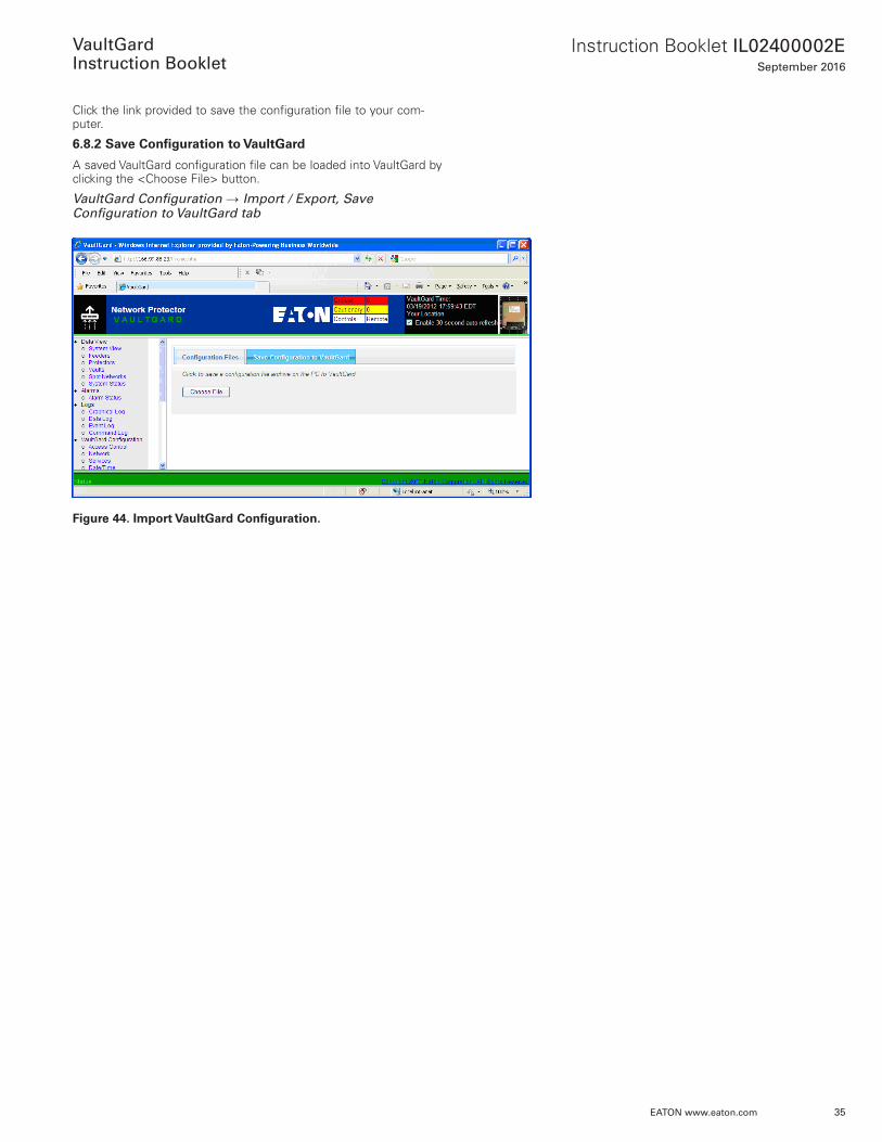
Click the link provided to save the configuration file to your com-puter .
6.8.2 Save Configuration to VaultGard
A saved VaultGard configuration file can be loaded into VaultGard by clicking the <Choose File> button .
VaultGard Configuration → Import / Export, Save Configuration to VaultGard tab
Figure 44. Import VaultGard Configuration.
36
Instruction Booklet IL02400002ESeptember 2016
EATON www.eaton.com
VaultGard
Instruction Booklet
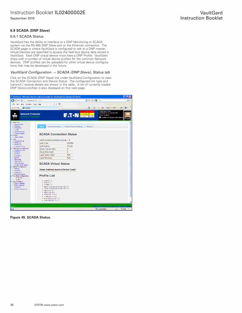
6.9 SCADA (DNP Slave)
6.9.1 SCADA Status
VaultGard has the ability to interface to a DNP Monitoring or SCADA system via the RS-485 DNP Slave port or the Ethernet connection . The SCADA page is where VaultGard is configured to talk to a DNP master . Virtual Devices are specified to access the field bus device data stored in VaultGard . Each DNP virtual device must have a DNP Profile . VaultGard ships with a number of virtual device profiles for the common Network devices . DNP profiles can be uploaded for other virtual device configura-tions that may be developed in the future .
VaultGard Configuration → SCADA (DNP Slave), Status tab
Click on the SCADA (DNP Slave) link under VaultGard Configuration to view the SCADA Connection and Device Status . The configured link type and transmit / receive details are shown in the table . A list of currently loaded DNP Device profiles is also displayed on this web page .
Figure 45. SCADA Status.
37
Instruction Booklet IL02400002ESeptember 2016
EATON www.eaton.com
VaultGard
Instruction Booklet
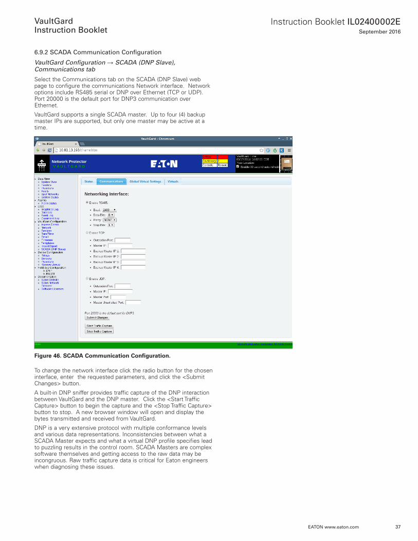
6.9.2 SCADA Communication Configuration
VaultGard Configuration → SCADA (DNP Slave), Communications tab
Select the Communications tab on the SCADA (DNP Slave) web page to configure the communications Network interface . Network options include RS485 serial or DNP over Ethernet (TCP or UDP) . Port 20000 is the default port for DNP3 communication over Ethernet .
VaultGard supports a single SCADA master . Up to four (4) backup master IPs are supported, but only one master may be active at a time .
Figure 46. SCADA Communication Configuration.
To change the network interface click the radio button for the chosen interface, enter the requested parameters, and click the <Submit Changes> button .
A built-in DNP sniffer provides traffic capture of the DNP interaction between VaultGard and the DNP master . Click the <Start Traffic Capture> button to begin the capture and the <Stop Traffic Capture> button to stop . A new browser window will open and display the bytes transmitted and received from VaultGard .
DNP is a very extensive protocol with multiple conformance levels and various data representations . Inconsistencies between what a SCADA Master expects and what a virtual DNP profile specifies lead to puzzling results in the control room . SCADA Masters are complex software themselves and getting access to the raw data may be incongruous . Raw traffic capture data is critical for Eaton engineers when diagnosing these issues .
38
Instruction Booklet IL02400002ESeptember 2016
EATON www.eaton.com
VaultGard
Instruction Booklet
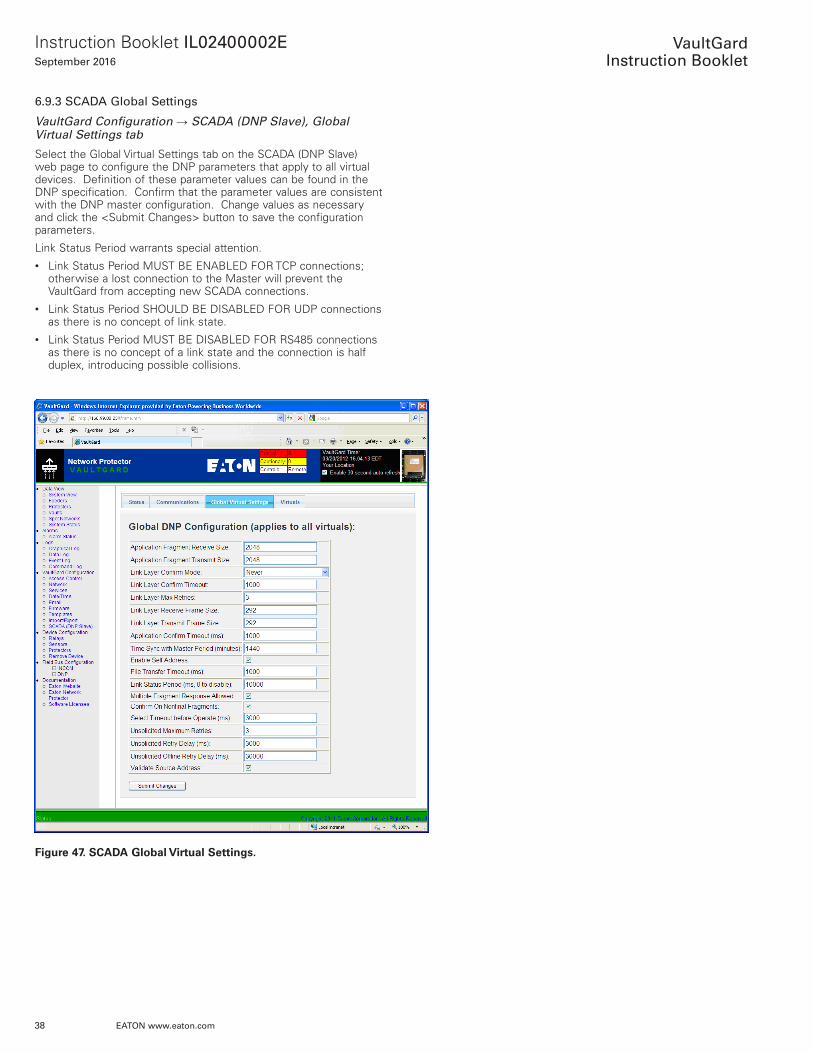
6.9.3 SCADA Global Settings
VaultGard Configuration → SCADA (DNP Slave), Global Virtual Settings tab
Select the Global Virtual Settings tab on the SCADA (DNP Slave) web page to configure the DNP parameters that apply to all virtual devices . Definition of these parameter values can be found in the DNP specification . Confirm that the parameter values are consistent with the DNP master configuration . Change values as necessary and click the <Submit Changes> button to save the configuration parameters .
Link Status Period warrants special attention .• Link Status Period MUST BE ENABLED FOR TCP connections;
otherwise a lost connection to the Master will prevent the VaultGard from accepting new SCADA connections .
• Link Status Period SHOULD BE DISABLED FOR UDP connections as there is no concept of link state .
• Link Status Period MUST BE DISABLED FOR RS485 connections as there is no concept of a link state and the connection is half duplex, introducing possible collisions .
Figure 47. SCADA Global Virtual Settings.
39
Instruction Booklet IL02400002ESeptember 2016
EATON www.eaton.com
VaultGard
Instruction Booklet
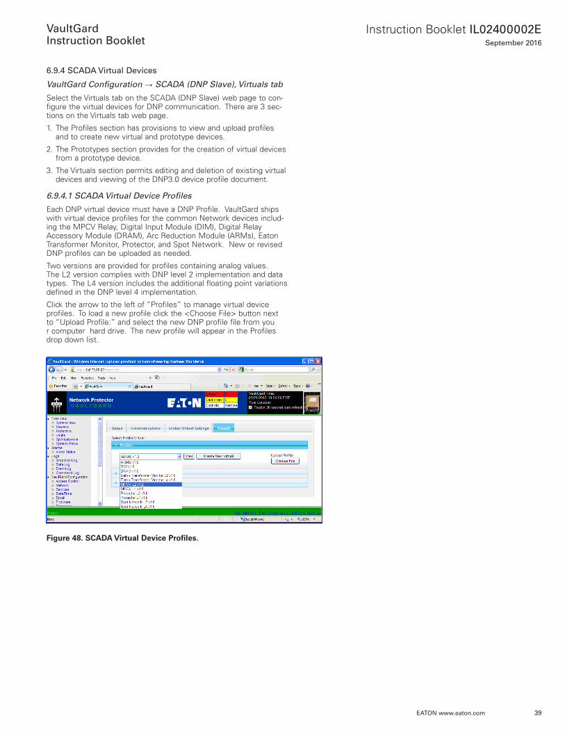
6.9.4 SCADA Virtual Devices
VaultGard Configuration → SCADA (DNP Slave), Virtuals tab
Select the Virtuals tab on the SCADA (DNP Slave) web page to con-figure the virtual devices for DNP communication . There are 3 sec-tions on the Virtuals tab web page .
1 . The Profiles section has provisions to view and upload profiles and to create new virtual and prototype devices .
2 . The Prototypes section provides for the creation of virtual devices from a prototype device .
3 . The Virtuals section permits editing and deletion of existing virtual devices and viewing of the DNP3 .0 device profile document .
6.9.4.1 SCADA Virtual Device Profiles
Each DNP virtual device must have a DNP Profile . VaultGard ships with virtual device profiles for the common Network devices includ-ing the MPCV Relay, Digital Input Module (DIM), Digital Relay Accessory Module (DRAM), Arc Reduction Module (ARMs), Eaton Transformer Monitor, Protector, and Spot Network . New or revised DNP profiles can be uploaded as needed .
Two versions are provided for profiles containing analog values . The L2 version complies with DNP level 2 implementation and data types . The L4 version includes the additional floating point variations defined in the DNP level 4 implementation .
Click the arrow to the left of “Profiles” to manage virtual device profiles . To load a new profile click the <Choose File> button next to “Upload Profile:” and select the new DNP profile file from you r computer hard drive . The new profile will appear in the Profiles drop down list .
Figure 48. SCADA Virtual Device Profiles.
40
Instruction Booklet IL02400002ESeptember 2016
EATON www.eaton.com
VaultGard
Instruction Booklet
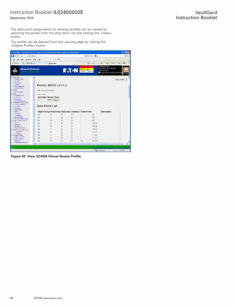
The data point assignments for existing profiles can be viewed by selecting the profile from the drop down list and clicking the <View> button .
The profile can be deleted from this viewing page by clicking the <Delete Profile> button .
Figure 49. View SCADA Virtual Device Profile.
41
Instruction Booklet IL02400002ESeptember 2016
EATON www.eaton.com
VaultGard
Instruction Booklet
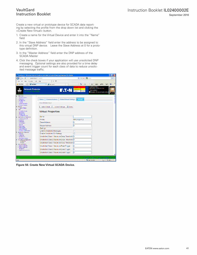
Create a new virtual or prototype device for SCADA data report-ing by selecting the profile from the drop down list and clicking the <Create New Virtual> button .
1 . Create a name for the Virtual Device and enter it into the “Name” field
2 . In the “Slave Address” field enter the address to be assigned to this virtual DNP device . Leave the Slave Address at 0 for a proto-type definition .
3 . In the “Master Address” field enter the DNP address of the SCADA Master
4 . Click the check boxes if your application will use unsolicited DNP messaging . Optional settings are also provided for a time delay and event trigger count for each class of data to reduce unsolic-ited message traffic .
Figure 50. Create New Virtual SCADA Device.
42
Instruction Booklet IL02400002ESeptember 2016
EATON www.eaton.com
VaultGard
Instruction Booklet
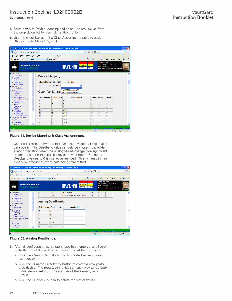
5 . Scroll down to Device Mapping and select the real device from the drop down list for each slot in the profile .
6 . Use the check boxes in the Class Assignments table to assign DNP points to Class 1, 2, or 3 .
Figure 51. Device Mapping & Class Assignments.
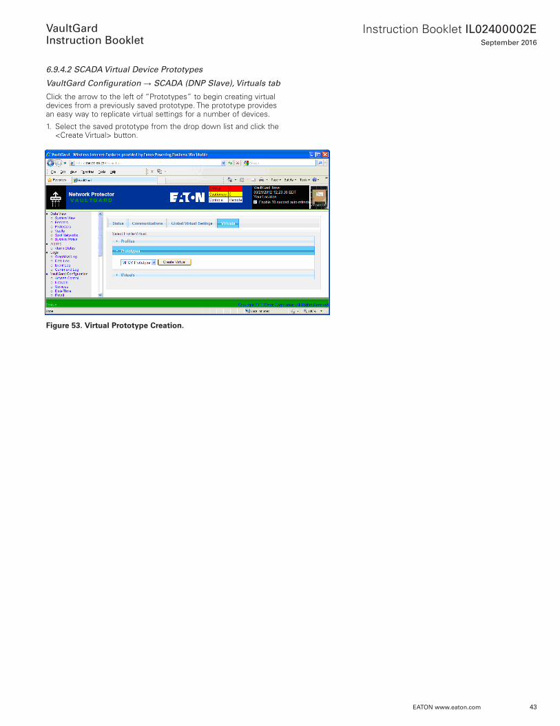
7 . Continue scrolling down to enter Deadband values for the analog data points . The Deadband values should be chosen to provide event notification when the analog values change by a significant amount based on the specific device environment . Setting all Deadband values to 0 is not recommended . This will result in an excessive amount of event data being transmitted .
Figure 52. Analog Deadbands.
8 . After all configuration parameters have been entered scroll back up to the top of the web page . Select one of the 3 choices:
a . Click the <Submit Virtual> button to create the new virtual DNP device .
b . Click the <Submit Prototype> button to create a new proto-type device . The prototype provides an easy way to replicate virtual device settings for a number of the same type of device .
c . Click the <Delete> button to delete the virtual device
43
Instruction Booklet IL02400002ESeptember 2016
EATON www.eaton.com
VaultGard
Instruction Booklet
6.9.4.2 SCADA Virtual Device Prototypes
VaultGard Configuration → SCADA (DNP Slave), Virtuals tab
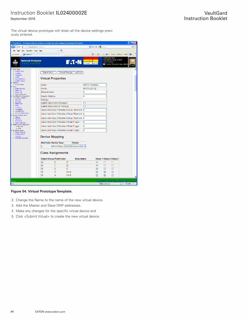
Click the arrow to the left of “Prototypes” to begin creating virtual devices from a previously saved prototype . The prototype provides an easy way to replicate virtual settings for a number of devices .
1 . Select the saved prototype from the drop down list and click the <Create Virtual> button .
Figure 53. Virtual Prototype Creation.
44
Instruction Booklet IL02400002ESeptember 2016
EATON www.eaton.com
VaultGard
Instruction Booklet
The virtual device prototype will retain all the device settings previ-ously entered .
Figure 54. Virtual Prototype Template.
2 . Change the Name to the name of the new virtual device .
3 . Add the Master and Slave DNP addresses .
4 . Make any changes for the specific virtual device and
5 . Click <Submit Virtual> to create the new virtual device .
45
Instruction Booklet IL02400002ESeptember 2016
EATON www.eaton.com
VaultGard
Instruction Booklet
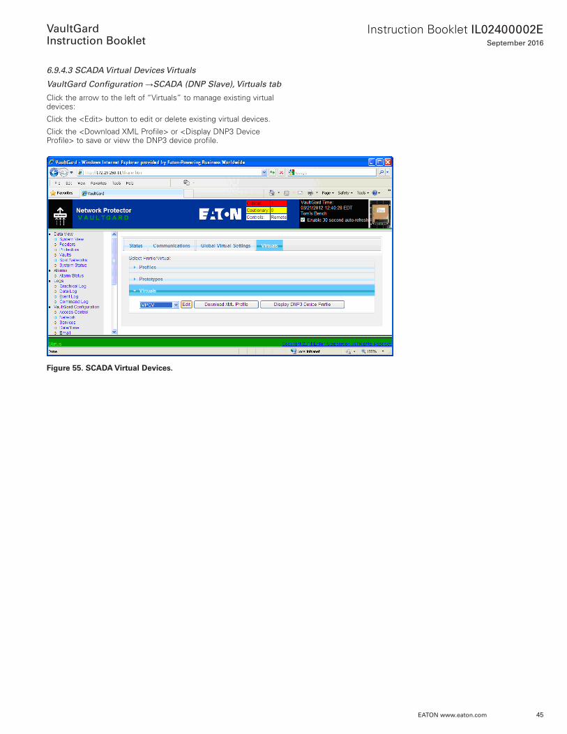
6.9.4.3 SCADA Virtual Devices Virtuals
VaultGard Configuration →SCADA (DNP Slave), Virtuals tab
Click the arrow to the left of “Virtuals” to manage existing virtual devices:
Click the <Edit> button to edit or delete existing virtual devices .
Click the <Download XML Profile> or <Display DNP3 Device Profile> to save or view the DNP3 device profile .
Figure 55. SCADA Virtual Devices.
46
Instruction Booklet IL02400002ESeptember 2016
EATON www.eaton.com
VaultGard
Instruction Booklet
Section 7: Device ConfigurationIndividual device settings for alarms, logging, and email are config-ured in the Device Configuration section . Protector, Feeder, Spot, and Vault configuration is also included in the Device Configuration section through the Protectors link .
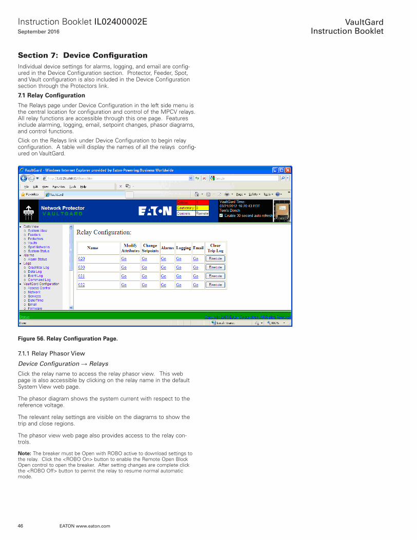
7.1 Relay Configuration
The Relays page under Device Configuration in the left side menu is the central location for configuration and control of the MPCV relays . All relay functions are accessible through this one page . Features include alarming, logging, email, setpoint changes, phasor diagrams, and control functions .
Click on the Relays link under Device Configuration to begin relay configuration . A table will display the names of all the relays config-ured on VaultGard .
Figure 56. Relay Configuration Page.
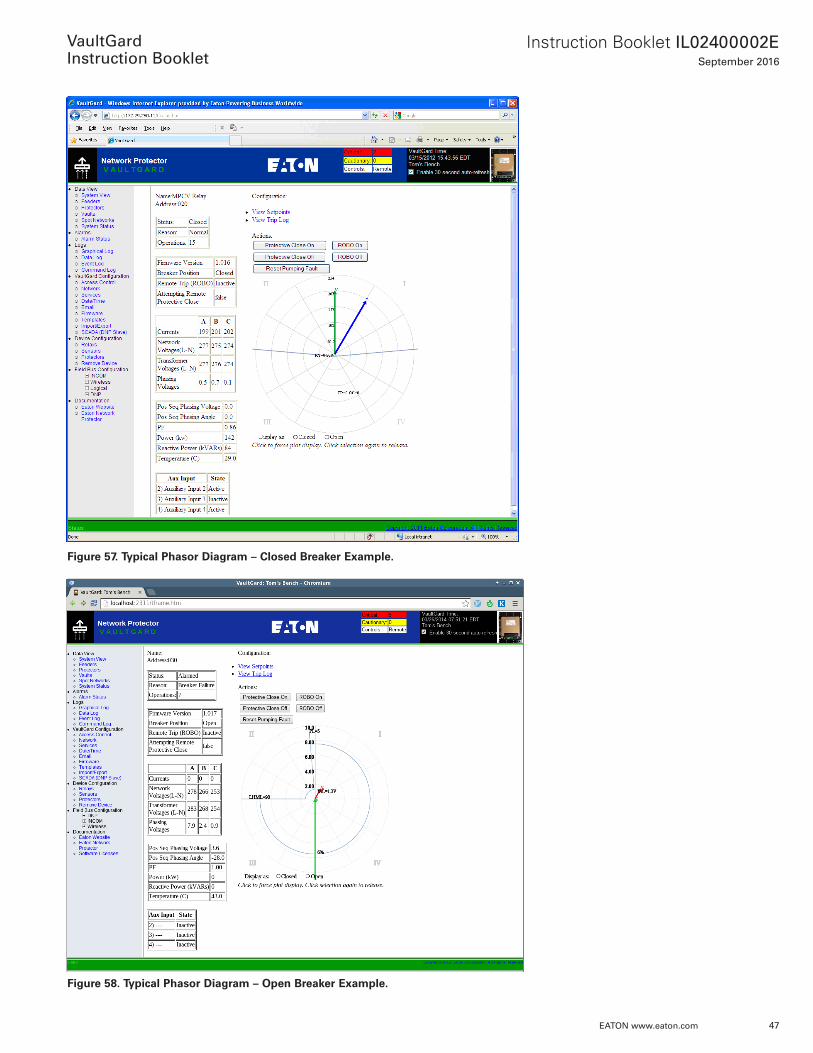
7.1.1 Relay Phasor View
Device Configuration → Relays
Click the relay name to access the relay phasor view . This web page is also accessible by clicking on the relay name in the default System View web page .
The phasor diagram shows the system current with respect to the reference voltage .
The relevant relay settings are visible on the diagrams to show the trip and close regions .
The phasor view web page also provides access to the relay con-trols .
ote:N The breaker must be Open with ROBO active to download settings to the relay . Click the <ROBO On> button to enable the Remote Open Block Open control to open the breaker . After setting changes are complete click the <ROBO Off> button to permit the relay to resume normal automatic mode .
47
Instruction Booklet IL02400002ESeptember 2016
EATON www.eaton.com
VaultGard
Instruction Booklet
Figure 57. Typical Phasor Diagram – Closed Breaker Example.
Figure 58. Typical Phasor Diagram – Open Breaker Example.
48
Instruction Booklet IL02400002ESeptember 2016
EATON www.eaton.com
VaultGard
Instruction Booklet
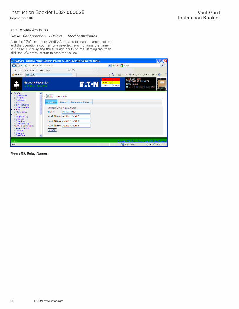
7.1.2 Modify Attributes
Device Configuration → Relays → Modify Attributes
Click the “Go” link under Modify Attributes to change names, colors, and the operations counter for a selected relay . Change the name for the MPCV relay and the auxiliary inputs on the Naming tab, then click the <Submit> button to save the values .
Figure 59. Relay Names.
49
Instruction Booklet IL02400002ESeptember 2016
EATON www.eaton.com
VaultGard
Instruction Booklet
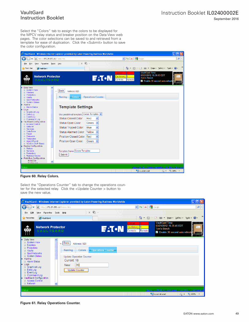
Select the “Colors” tab to assign the colors to be displayed for the MPCV relay status and breaker position on the Data View web pages . The color selections can be saved to and retrieved from a template for ease of duplication . Click the <Submit> button to save the color configuration .
Figure 60. Relay Colors.
Select the “Operations Counter” tab to change the operations coun-ter for the selected relay . Click the <Update Counter > button to save the new value .
Figure 61. Relay Operations Counter.
50
Instruction Booklet IL02400002ESeptember 2016
EATON www.eaton.com
VaultGard
Instruction Booklet
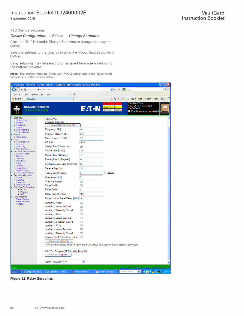
7 .1 .3 Change Setpoints
Device Configuration → Relays → Change Setpoints
Click the “Go” link under Change Setpoints to change the relay set-points .
Save the settings to the relay by clicking the <Download Setpoints > button .
Relay setpoints may be saved to or retrieved from a template using the buttons provided .
ote:N The breaker must be Open with ROBO active before the <Download Setpoints > button will be active!
Figure 62. Relay Setpoints.
51
Instruction Booklet IL02400002ESeptember 2016
EATON www.eaton.com
VaultGard
Instruction Booklet
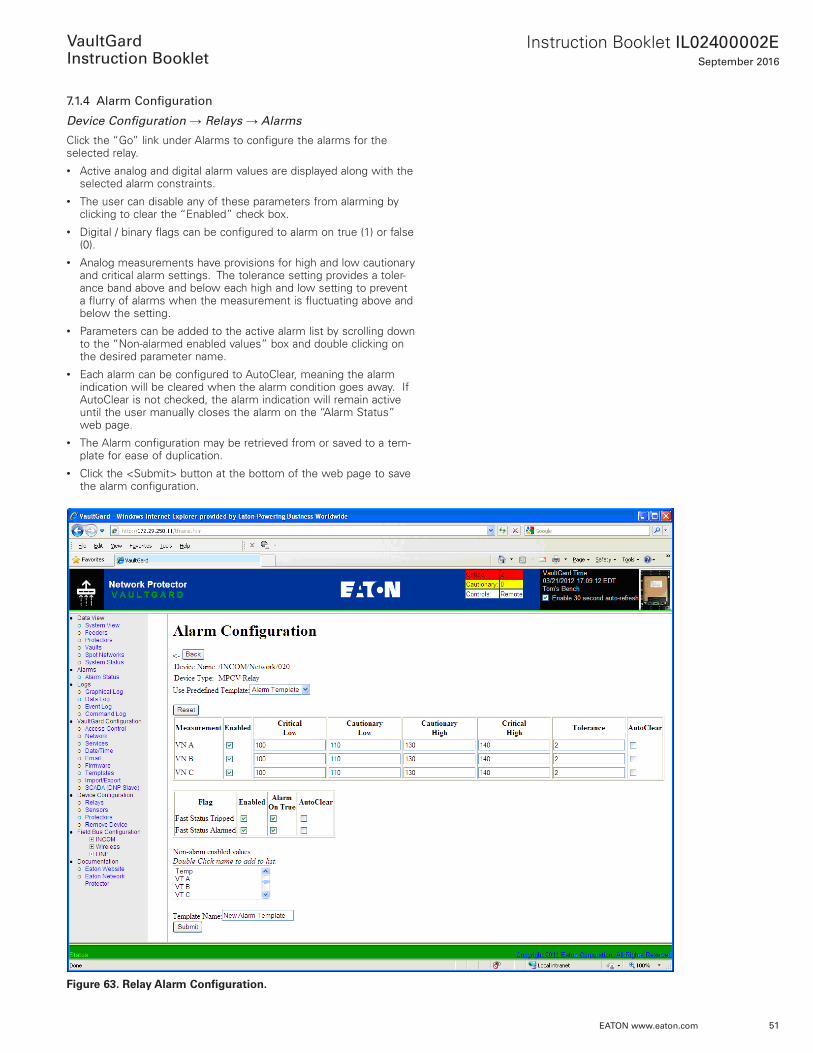
7.1.4 Alarm Configuration
Device Configuration → Relays → Alarms
Click the “Go” link under Alarms to configure the alarms for the selected relay . • Active analog and digital alarm values are displayed along with the
selected alarm constraints . • The user can disable any of these parameters from alarming by
clicking to clear the “Enabled” check box .• Digital / binary flags can be configured to alarm on true (1) or false
(0) . • Analog measurements have provisions for high and low cautionary
and critical alarm settings . The tolerance setting provides a toler-ance band above and below each high and low setting to prevent a flurry of alarms when the measurement is fluctuating above and below the setting .
• Parameters can be added to the active alarm list by scrolling down to the “Non-alarmed enabled values” box and double clicking on the desired parameter name .
• Each alarm can be configured to AutoClear, meaning the alarm indication will be cleared when the alarm condition goes away . If AutoClear is not checked, the alarm indication will remain active until the user manually closes the alarm on the “Alarm Status” web page .
• The Alarm configuration may be retrieved from or saved to a tem-plate for ease of duplication .
• Click the <Submit> button at the bottom of the web page to save the alarm configuration .
Figure 63. Relay Alarm Configuration.
52
Instruction Booklet IL02400002ESeptember 2016
EATON www.eaton.com
VaultGard
Instruction Booklet
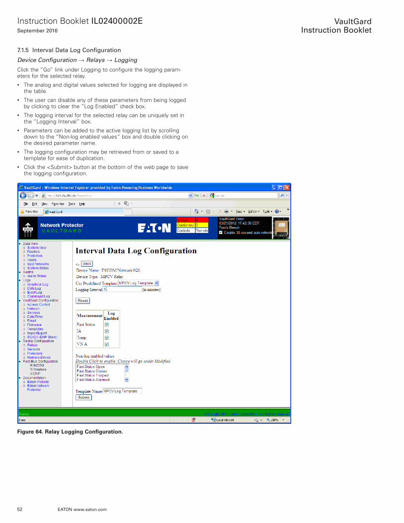
7.1.5 Interval Data Log Configuration
Device Configuration → Relays → Logging
Click the “Go” link under Logging to configure the logging param-eters for the selected relay . • The analog and digital values selected for logging are displayed in
the table .• The user can disable any of these parameters from being logged
by clicking to clear the “Log Enabled” check box .• The logging interval for the selected relay can be uniquely set in
the “Logging Interval” box .• Parameters can be added to the active logging list by scrolling
down to the “Non-log enabled values” box and double clicking on the desired parameter name .
• The logging configuration may be retrieved from or saved to a template for ease of duplication .
• Click the <Submit> button at the bottom of the web page to save the logging configuration .
Figure 64. Relay Logging Configuration.
53
Instruction Booklet IL02400002ESeptember 2016
EATON www.eaton.com
VaultGard
Instruction Booklet
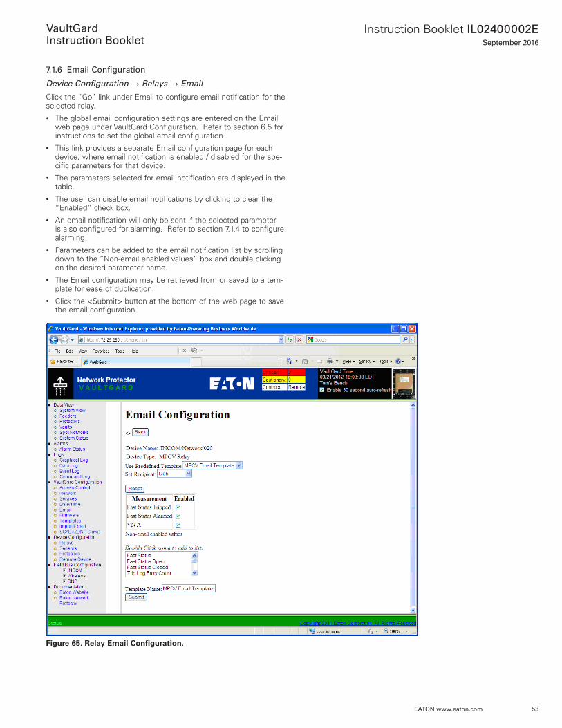
7.1.6 Email Configuration
Device Configuration → Relays → Email
Click the “Go” link under Email to configure email notification for the selected relay . • The global email configuration settings are entered on the Email
web page under VaultGard Configuration . Refer to section 6 .5 for instructions to set the global email configuration .
• This link provides a separate Email configuration page for each device, where email notification is enabled / disabled for the spe-cific parameters for that device .
• The parameters selected for email notification are displayed in the table .
• The user can disable email notifications by clicking to clear the “Enabled” check box .
• An email notification will only be sent if the selected parameter is also configured for alarming . Refer to section 7 .1 .4 to configure alarming .
• Parameters can be added to the email notification list by scrolling down to the “Non-email enabled values” box and double clicking on the desired parameter name .
• The Email configuration may be retrieved from or saved to a tem-plate for ease of duplication .
• Click the <Submit> button at the bottom of the web page to save the email configuration .
Figure 65. Relay Email Configuration.

54
Instruction Booklet IL02400002ESeptember 2016
EATON www.eaton.com
VaultGard
Instruction Booklet
7.1.7 Clear Trip Log
Device Configuration → Relays
Clicking the <Execute> button will clear all trip logs for that particular MPCV relay.
ote:N Once this command is initiated, all trip logs will be lost .
7.2 Sensor Configuration
The Sensors page under Device Configuration in the left side menu is the central location for configuration of the Wireless Sensors .
Device Configuration → Sensors
Click on the Sensors link under Device Configuration to begin sen-sor configuration . A table will display the names of all the sensors configured on VaultGard . Use the links provided to configure alarms and logging in a similar manner to the relay configuration described in section 7 .1
Figure 66. Sensor Configuration.

55
Instruction Booklet IL02400002ESeptember 2016
EATON www.eaton.com
VaultGard
Instruction Booklet
7.3 Protectors
Protector, Feeder, Spot, and Vault configuration is handled under Device Configuration → Protectors .
The Protector Summary tab shows a summary of the configured protectors and the protector accessories .
Figure 67. Protector Summary Screen.
The first step to configuring protectors, feeders, vaults, and spot net-works is to create a new feeder and add a protector to it . Both of these tasks are completed on the Feeders tab .
Navigate to the Feeders tab of Device Configuration → Protectors.
Figure 68. Feeder Tab – Creating a Feeder.
56
Instruction Booklet IL02400002ESeptember 2016
EATON www.eaton.com
VaultGard
Instruction Booklet
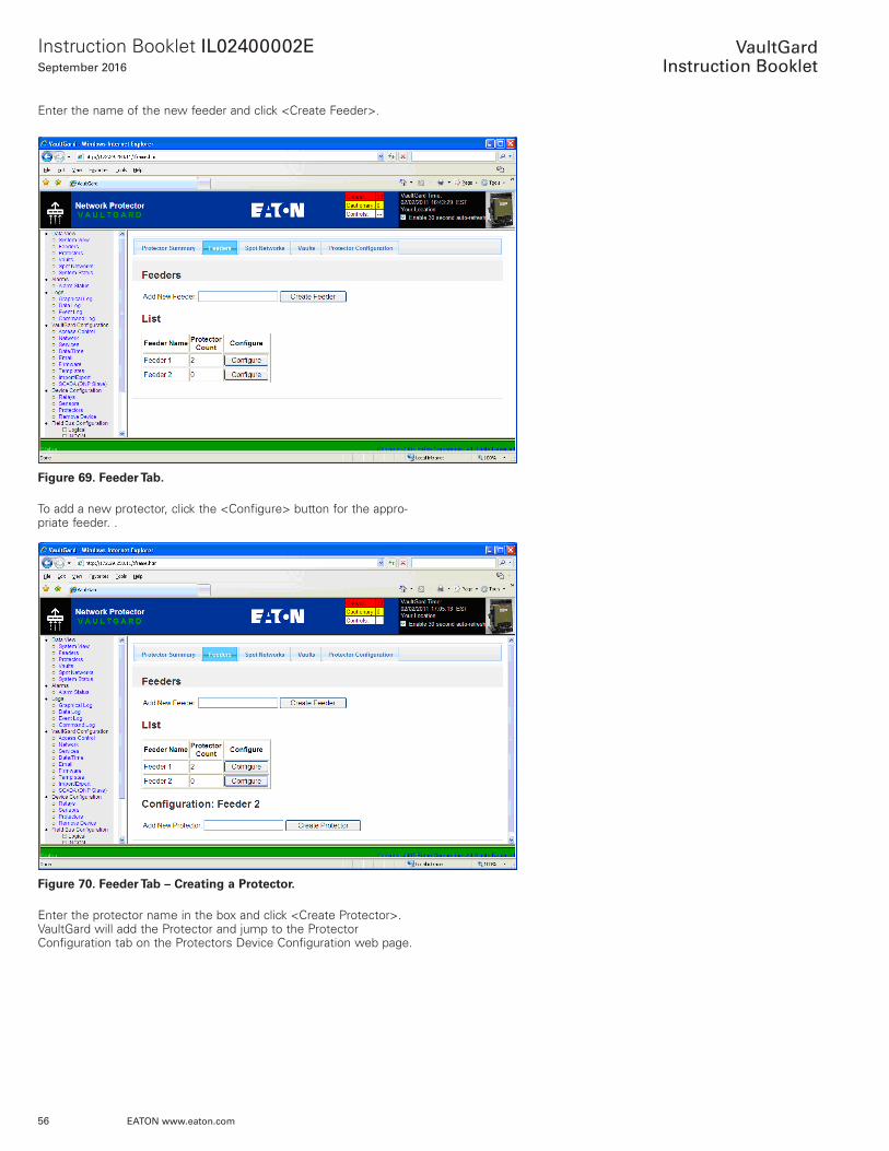
Enter the name of the new feeder and click <Create Feeder> .
Figure 69. Feeder Tab.
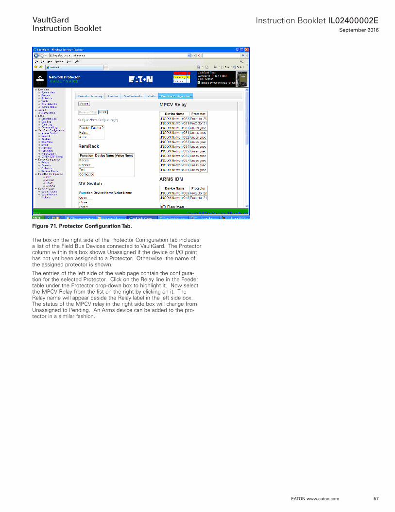
To add a new protector, click the <Configure> button for the appro-priate feeder . .
Figure 70. Feeder Tab – Creating a Protector.
Enter the protector name in the box and click <Create Protector> . VaultGard will add the Protector and jump to the Protector Configuration tab on the Protectors Device Configuration web page .
57
Instruction Booklet IL02400002ESeptember 2016
EATON www.eaton.com
VaultGard
Instruction Booklet
Figure 71. Protector Configuration Tab.
The box on the right side of the Protector Configuration tab includes a list of the Field Bus Devices connected to VaultGard . The Protector column within this box shows Unassigned if the device or I/O point has not yet been assigned to a Protector . Otherwise, the name of the assigned protector is shown .
The entries of the left side of the web page contain the configura-tion for the selected Protector . Click on the Relay line in the Feeder table under the Protector drop-down box to highlight it . Now select the MPCV Relay from the list on the right by clicking on it . The Relay name will appear beside the Relay label in the left side box . The status of the MPCV relay in the right side box will change from Unassigned to Pending . An Arms device can be added to the pro-tector in a similar fashion .
58
Instruction Booklet IL02400002ESeptember 2016
EATON www.eaton.com
VaultGard
Instruction Booklet
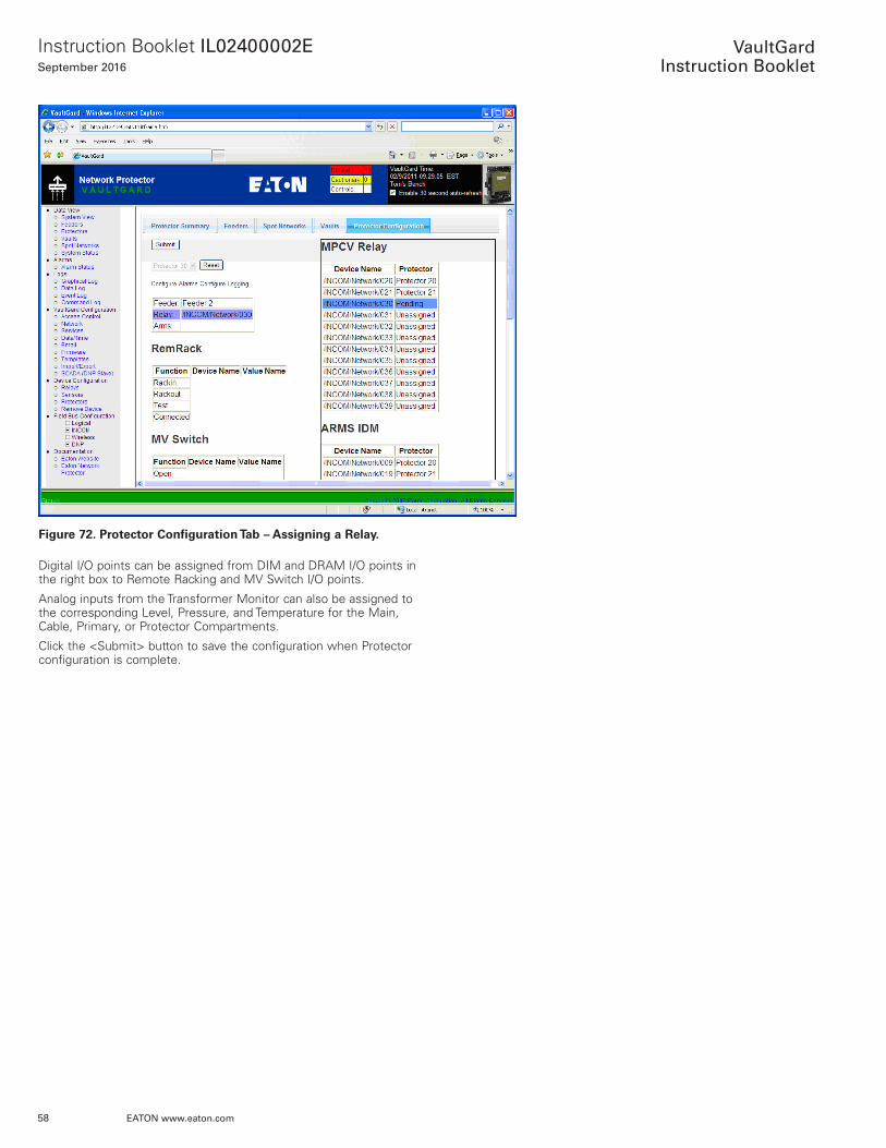
Figure 72. Protector Configuration Tab – Assigning a Relay.
Digital I/O points can be assigned from DIM and DRAM I/O points in the right box to Remote Racking and MV Switch I/O points .
Analog inputs from the Transformer Monitor can also be assigned to the corresponding Level, Pressure, and Temperature for the Main, Cable, Primary, or Protector Compartments .
Click the <Submit> button to save the configuration when Protector configuration is complete .
59
Instruction Booklet IL02400002ESeptember 2016
EATON www.eaton.com
VaultGard
Instruction Booklet
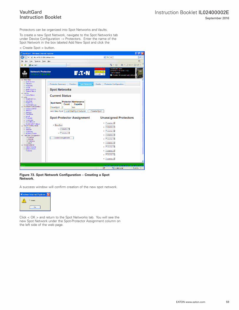
Protectors can be organized into Spot Networks and Vaults .
To create a new Spot Network, navigate to the Spot Networks tab under Device Configuration → Protectors . Enter the name of the Spot Network in the box labeled Add New Spot and click the
< Create Spot > button .
Figure 73. Spot Network Configuration – Creating a Spot Network.
A success window will confirm creation of the new spot network .
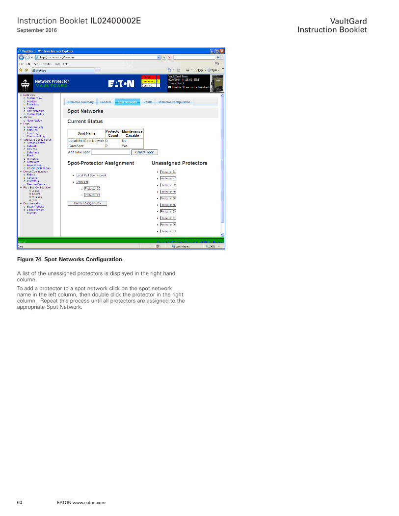
Click < OK > and return to the Spot Networks tab . You will see the new Spot Network under the Spot-Protector Assignment column on the left side of the web page .
60
Instruction Booklet IL02400002ESeptember 2016
EATON www.eaton.com
VaultGard
Instruction Booklet
Figure 74. Spot Networks Configuration.
A list of the unassigned protectors is displayed in the right hand column .
To add a protector to a spot network click on the spot network name in the left column, then double click the protector in the right column . Repeat this process until all protectors are assigned to the appropriate Spot Network .
61
Instruction Booklet IL02400002ESeptember 2016
EATON www.eaton.com
VaultGard
Instruction Booklet
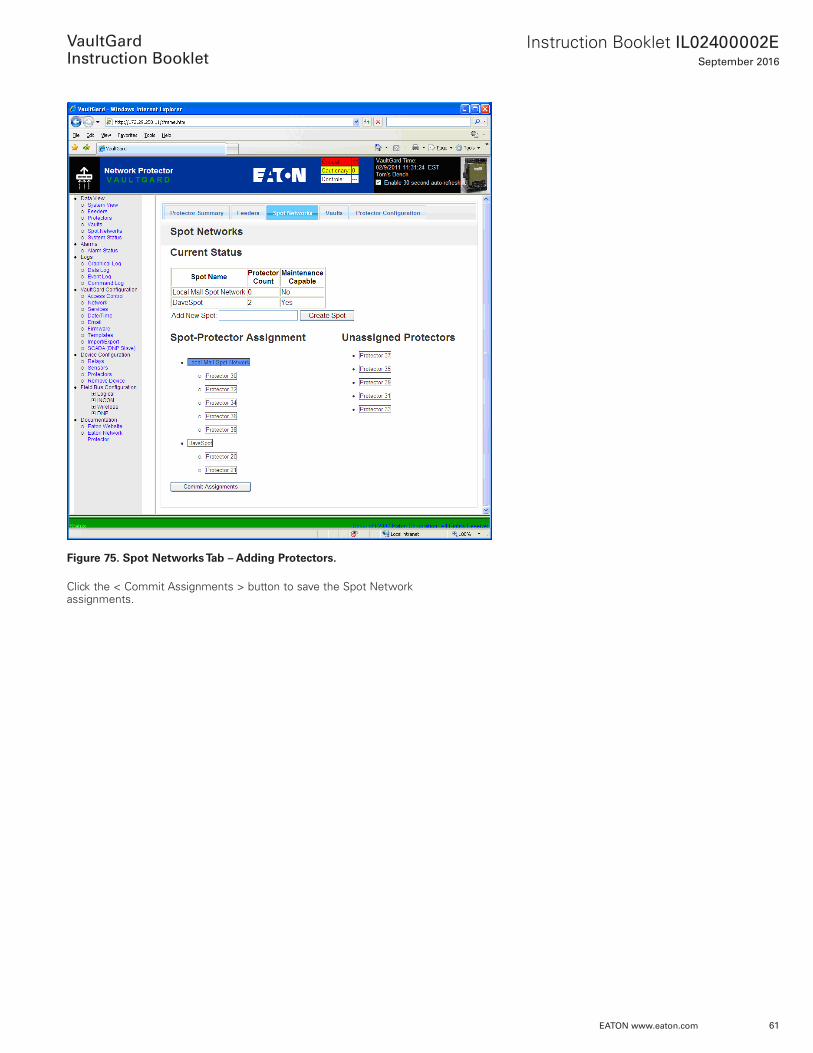
Figure 75. Spot Networks Tab – Adding Protectors.
Click the < Commit Assignments > button to save the Spot Network assignments .

62
Instruction Booklet IL02400002ESeptember 2016
EATON www.eaton.com
VaultGard
Instruction Booklet
Protectors can also be configured into Vaults along with I/O devices .
To create a new Vault, navigate to the Vaults tab under Device Configuration → Protectors .
Enter the name of the Vault in the box labeled Add New Vault and click the < Create Vault > button .
Figure 76. Vaults Tab – Creating a Vault.
A success window will confirm creation of the new vault .
63
Instruction Booklet IL02400002ESeptember 2016
EATON www.eaton.com
VaultGard
Instruction Booklet
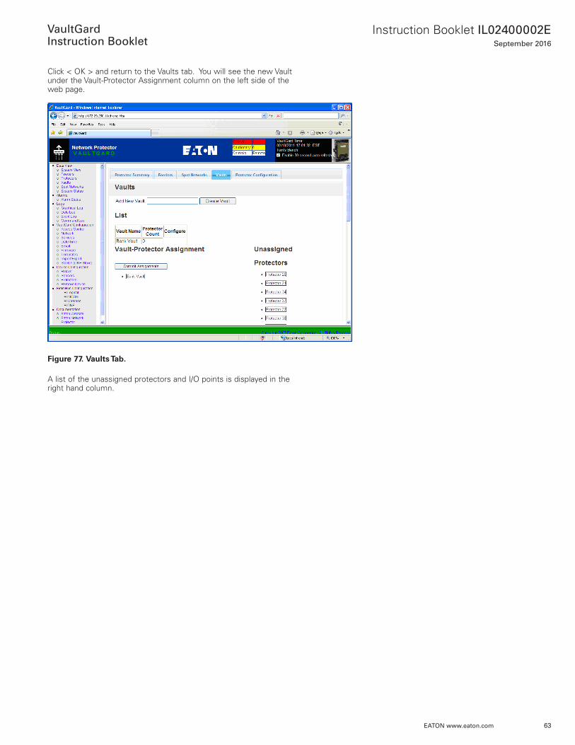
Click < OK > and return to the Vaults tab . You will see the new Vault under the Vault-Protector Assignment column on the left side of the web page .
Figure 77. Vaults Tab.
A list of the unassigned protectors and I/O points is displayed in the right hand column .
64
Instruction Booklet IL02400002ESeptember 2016
EATON www.eaton.com
VaultGard
Instruction Booklet
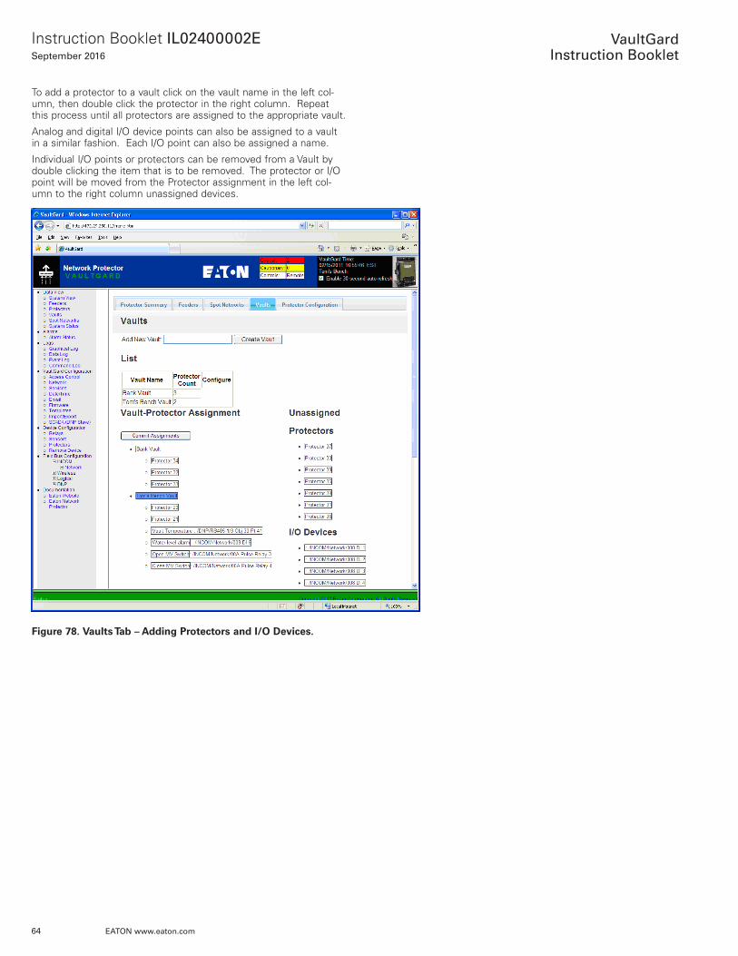
To add a protector to a vault click on the vault name in the left col-umn, then double click the protector in the right column . Repeat this process until all protectors are assigned to the appropriate vault .
Analog and digital I/O device points can also be assigned to a vault in a similar fashion . Each I/O point can also be assigned a name .
Individual I/O points or protectors can be removed from a Vault by double clicking the item that is to be removed . The protector or I/O point will be moved from the Protector assignment in the left col-umn to the right column unassigned devices .
Figure 78. Vaults Tab – Adding Protectors and I/O Devices.
65
Instruction Booklet IL02400002ESeptember 2016
EATON www.eaton.com
VaultGard
Instruction Booklet
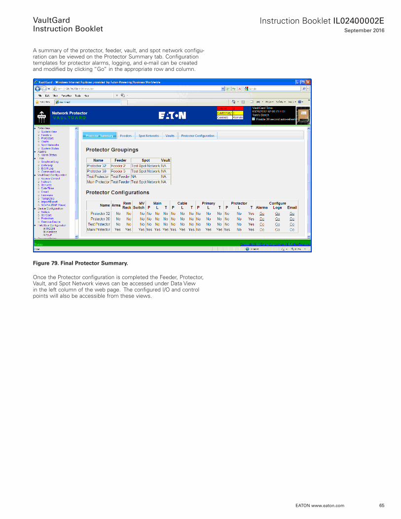
A summary of the protector, feeder, vault, and spot network configu-ration can be viewed on the Protector Summary tab . Configuration templates for protector alarms, logging, and e-mail can be created and modified by clicking “Go” in the appropriate row and column .
Figure 79. Final Protector Summary.
Once the Protector configuration is completed the Feeder, Protector, Vault, and Spot Network views can be accessed under Data View in the left column of the web page . The configured I/O and control points will also be accessible from these views .
66
Instruction Booklet IL02400002ESeptember 2016
EATON www.eaton.com
VaultGard
Instruction Booklet
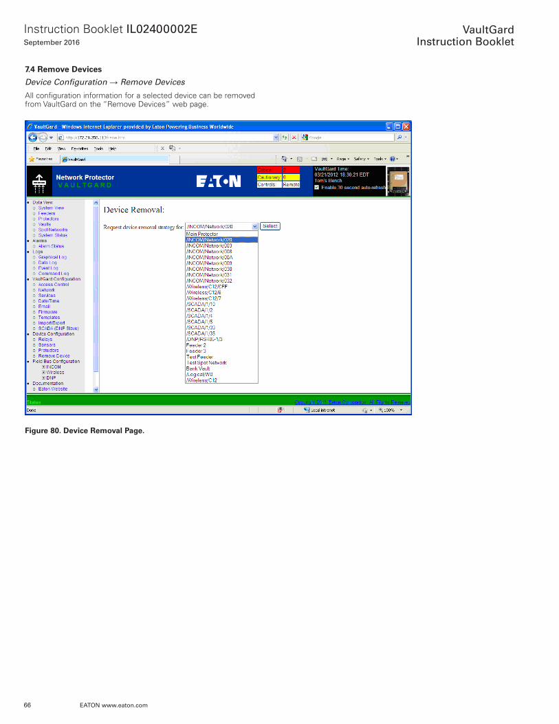
7.4 Remove Devices
Device Configuration → Remove Devices
All configuration information for a selected device can be removed from VaultGard on the “Remove Devices” web page .
Figure 80. Device Removal Page.
67
Instruction Booklet IL02400002ESeptember 2016
EATON www.eaton.com
VaultGard
Instruction Booklet
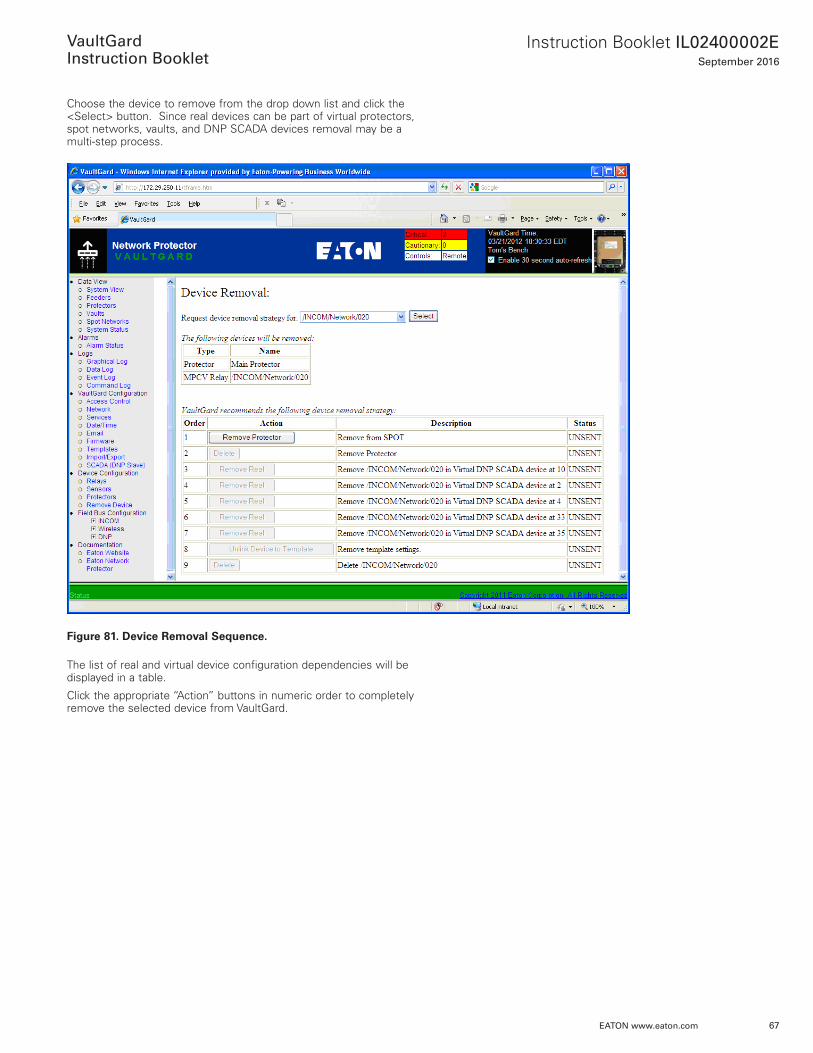
Choose the device to remove from the drop down list and click the <Select> button . Since real devices can be part of virtual protectors, spot networks, vaults, and DNP SCADA devices removal may be a multi-step process .
Figure 81. Device Removal Sequence.
The list of real and virtual device configuration dependencies will be displayed in a table .
Click the appropriate “Action” buttons in numeric order to completely remove the selected device from VaultGard .
68
Instruction Booklet IL02400002ESeptember 2016
EATON www.eaton.com
VaultGard
Instruction Booklet
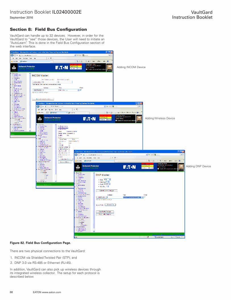
Section 8: Field Bus ConfigurationVaultGard can handle up to 32 devices . However, in order for the VaultGard to “see” those devices, the User will need to initiate an “AutoLearn” . This is done in the Field Bus Configuration section of the web interface .
Figure 82. Field Bus Configuration Page.
There are two physical connections to the VaultGard:
1 . INCOM via Shielded Twisted Pair (STP); and
2 . DNP 3 .0 via RS-485 or Ethernet (RJ-45) .
In addition, VaultGard can also pick up wireless devices through its integrated wireless collector . The setup for each protocol is described below .
Adding INCOM Device
Adding Wireless Device
Adding DNP Device
69
Instruction Booklet IL02400002ESeptember 2016
EATON www.eaton.com
VaultGard
Instruction Booklet
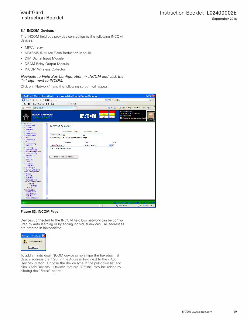
8.1 INCOM Devices
The INCOM field bus provides connection to the following INCOM devices:
• MPCV relay• NPARMS-IDM Arc Flash Reduction Module• DIM Digital Input Module• DRAM Relay Output Module• INCOM Wireless Collector
Navigate to Field Bus Configuration → INCOM and click the “+” sign next to INCOM.
Click on “Network” and the following screen will appear .
Figure 83. INCOM Page.
Devices connected to the INCOM field bus network can be config-ured by auto learning or by adding individual devices . All addresses are entered in hexadecimal .
To add an individual INCOM device simply type the hexadecimal device address (i e ” 2B) in the Address field next to the <Add Device> button . Choose the device Type in the pull-down list and click <Add Device> . Devices that are “Offline” may be added by clicking the “Force” option .
70
Instruction Booklet IL02400002ESeptember 2016
EATON www.eaton.com
VaultGard
Instruction Booklet
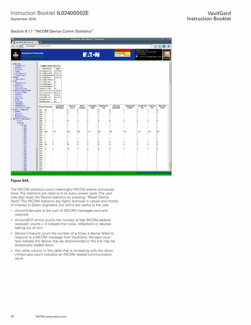
Section 8.1.1 “INCOM Device Comm Statistics”
Figure 83A.
The INCOM statistics count meaningful INCOM events and excep-tions . The statistics are reset to 0 on every power cycle . The user may also reset the Device statistics by pressing “Reset Device Stats” . The INCOM statistics are highly technical in nature and mostly of interest to Eaton engineers, but some are useful to the user .• sIncomInterrupts is the sum of INCOM messages sent and
received .• sIncomBCH errors counts the number of bad INCOM packets
received; counts > 0 indicate line noise, reflections or devices talking out of turn .
• Device Timeouts count the number of a times a device failed to respond to a INCOM message from VaultGard . Nonzero coun-ters indicate the device may be disconnected or the line may be excessively loaded down .
• Any other column in this table that is increasing with the sInco-mInterrupts count indicates an INCOM related communication issue .
71
Instruction Booklet IL02400002ESeptember 2016
EATON www.eaton.com
VaultGard
Instruction Booklet
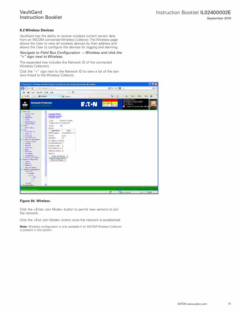
8.2 Wireless Devices
VaultGard has the ability to receive wireless current sensor data from an INCOM connected Wireless Collector . The Wireless page allows the User to view all wireless devices by their address and allows the User to configure the devices for logging and alarming .
Navigate to Field Bus Configuration → Wireless and click the “+” sign next to Wireless.
The expanded tree includes the Network ID of the connected Wireless Collectors .
Click the “+” sign next to the Network ID to view a list of the sen-sors linked to the Wireless Collector .
Figure 84. Wireless.
Click the <Enter Join Mode> button to permit new sensors to join the network .
Click the <Exit Join Mode> button once the network is established .
ote:N Wireless configuration is only available if an INCOM Wireless Collector is present in the system .
72
Instruction Booklet IL02400002ESeptember 2016
EATON www.eaton.com
VaultGard
Instruction Booklet
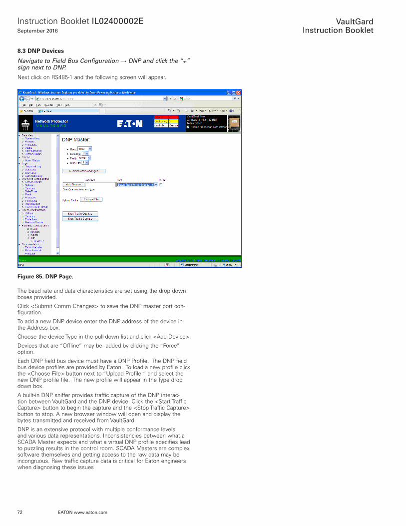
8.3 DNP Devices
Navigate to Field Bus Configuration → DNP and click the “+” sign next to DNP.
Next click on RS485-1 and the following screen will appear .
Figure 85. DNP Page.
The baud rate and data characteristics are set using the drop down boxes provided .
Click <Submit Comm Changes> to save the DNP master port con-figuration .
To add a new DNP device enter the DNP address of the device in the Address box .
Choose the device Type in the pull-down list and click <Add Device> .
Devices that are “Offline” may be added by clicking the “Force” option .
Each DNP field bus device must have a DNP Profile . The DNP field bus device profiles are provided by Eaton . To load a new profile click the <Choose File> button next to “Upload Profile:” and select the new DNP profile file . The new profile will appear in the Type drop down box .
A built-in DNP sniffer provides traffic capture of the DNP interac-tion between VaultGard and the DNP device . Click the <Start Traffic Capture> button to begin the capture and the <Stop Traffic Capture> button to stop . A new browser window will open and display the bytes transmitted and received from VaultGard .
DNP is an extensive protocol with multiple conformance levels and various data representations . Inconsistencies between what a SCADA Master expects and what a virtual DNP profile specifies lead to puzzling results in the control room . SCADA Masters are complex software themselves and getting access to the raw data may be incongruous . Raw traffic capture data is critical for Eaton engineers when diagnosing these issues
73
Instruction Booklet IL02400002ESeptember 2016
EATON www.eaton.com
VaultGard
Instruction Booklet
Section 8.3.1 “DNP Device View”
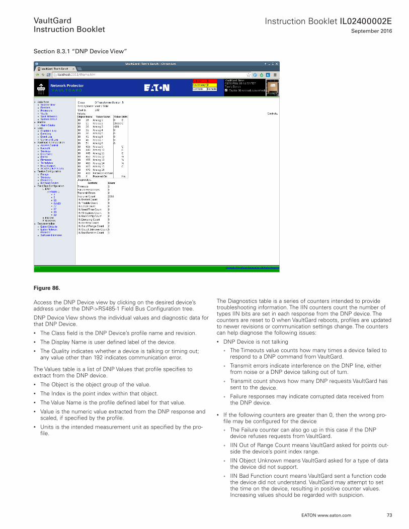
Figure 86.
Access the DNP Device view by clicking on the desired device’s address under the DNP->RS485-1 Field Bus Configuration tree .
DNP Device View shows the individual values and diagnostic data for that DNP Device .• The Class field is the DNP Device’s profile name and revision .• The Display Name is user defined label of the device .• The Quality indicates whether a device is talking or timing out;
any value other than 192 indicates communication error .
The Values table is a list of DNP Values that profile specifies to extract from the DNP device .• The Object is the object group of the value .• The Index is the point index within that object .• The Value Name is the profile defined label for that value .• Value is the numeric value extracted from the DNP response and
scaled, if specified by the profile .• Units is the intended measurement unit as specified by the pro-
file .
The Diagnostics table is a series of counters intended to provide troubleshooting information . The IIN counters count the number of types IIN bits are set in each response from the DNP device . The counters are reset to 0 when VaultGard reboots, profiles are updated to newer revisions or communication settings change . The counters can help diagnose the following issues:• DNP Device is not talking
• The Timeouts value counts how many times a device failed to respond to a DNP command from VaultGard .
• Transmit errors indicate interference on the DNP line, either from noise or a DNP device talking out of turn .
• Transmit count shows how many DNP requests VaultGard has sent to the device .
• Failure responses may indicate corrupted data received from the DNP device .
• If the following counters are greater than 0, then the wrong pro-file may be configured for the device• The Failure counter can also go up in this case if the DNP
device refuses requests from VaultGard .
• IIN Out of Range Count means VaultGard asked for points out-side the device’s point index range .
• IIN Object Unknown means VaultGard asked for a type of data the device did not support .
• IIN Bad Function count means VaultGard sent a function code the device did not understand . VaultGard may attempt to set the time on the device, resulting in positive counter values . Increasing values should be regarded with suspicion .

74
Instruction Booklet IL02400002ESeptember 2016
EATON www.eaton.com
VaultGard
Instruction Booklet
• If the following counters are greater than 0, then the DNP device is encountering issues• IIN Restart count indicates the device has restarted .
• IIN Trouble count indicates an abnormal condition in the DNP device .
• IIN Bad Config count indicates that the DNP device has a bad configuration .
• Control issues• IIN Executing count indicates device refused a control because
it was still busy executing a previous control .
• IIN Local count indicates that the device is in local mode and may refuse commands from VaultGard .
• Data issues• IIN Overflow count indicates data events are happening faster
than VaultGard is polling them .
In Figure 86, there is an IIN Out of Range count of 2 and 1 bad func-tion code .
In this case, we have purposely misconfigured an 8 analog input module with a 16 analog input device profile, thus resulting in an Out of Range error .
Section 9: System Setup Using the Serial PortThe Internet Address and Configuration and Control Passwords may be entered via the serial port on VaultGard . Connect the VaultGard serial port to a serial port on a PC executing PuTTY, HyperTerminal, or your favorite terminal emulator application . PuTTY is a free and open source terminal emulator application that can be downloaded from the Internet .
Select the “Serial” Connection type in PuTTY .
Make sure the Serial line (COM1 or COM??) matches the serial port connector in use .
Set the Speed to 115200 .
Click <Open> to establish the connection .
Figure 87.
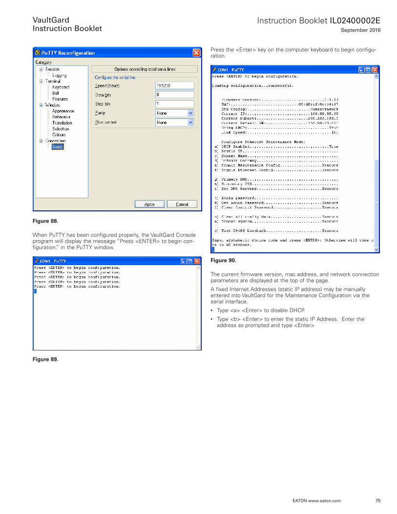
If necessary, set the Serial Connection options as shown:• Use the serial port settings:
• Bits per second: 115200
• Data bits: 8
• Parity: None
• Stop bits: 1
• Flow Control: None
75
Instruction Booklet IL02400002ESeptember 2016
EATON www.eaton.com
VaultGard
Instruction Booklet
Figure 88.
When PuTTY has been configured properly, the VaultGard Console program will display the message “Press <ENTER> to begin con-figuration .” in the PuTTY window .
Figure 89.
Press the <Enter> key on the computer keyboard to begin configu-ration .
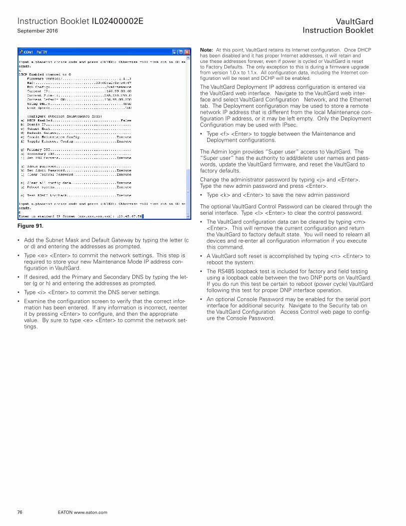
Figure 90.
The current firmware version, mac address, and network connection parameters are displayed at the top of the page .
A fixed Internet Addresses (static IP address) may be manually entered into VaultGard for the Maintenance Configuration via the serial interface . • Type <a> <Enter> to disable DHCP .• Type <b> <Enter> to enter the static IP Address . Enter the
address as prompted and type <Enter>
76
Instruction Booklet IL02400002ESeptember 2016
EATON www.eaton.com
VaultGard
Instruction Booklet
Figure 91.
• Add the Subnet Mask and Default Gateway by typing the letter (c or d) and entering the addresses as prompted .
• Type <e> <Enter> to commit the network settings . This step is required to store your new Maintenance Mode IP address con-figuration in VaultGard .
• If desired, add the Primary and Secondary DNS by typing the let-ter (g or h) and entering the addresses as prompted .
• Type <i> <Enter> to commit the DNS server settings . • Examine the configuration screen to verify that the correct infor-
mation has been entered . If any information is incorrect, reenter it by pressing <Enter> to configure, and then the appropriate value . By sure to type <e> <Enter> to commit the network set-tings .
ote:N At this point, VaultGard retains its Internet configuration . Once DHCP has been disabled and it has proper Internet addresses, it will retain and use these addresses forever, even if power is cycled or VaultGard is reset to Factory Defaults . The only exception to this is during a firmware upgrade from version 1 .0 .x to 1 .1 .x . All configuration data, including the Internet con-figuration will be reset and DCHP will be enabled .
The VaultGard Deployment IP address configuration is entered via the VaultGard web interface . Navigate to the VaultGard web inter-face and select VaultGard Configuration Network, and the Ethernet tab . The Deployment configuration may be used to store a remote network IP address that is different from the local Maintenance con-figuration IP address, or it may be left empty . Only the Deployment Configuration may be used with IPsec . • Type <f> <Enter> to toggle between the Maintenance and
Deployment configurations .
The Admin login provides “Super user” access to VaultGard . The “Super user” has the authority to add/delete user names and pass-words, update the VaultGard firmware, and reset the VaultGard to factory defaults .
Change the administrator password by typing <j> and <Enter> . Type the new admin password and press <Enter> . • Type <k> and <Enter> to save the new admin password
The optional VaultGard Control Password can be cleared through the serial interface . Type <l> <Enter> to clear the control password .• The VaultGard configuration data can be cleared by typing <m>
<Enter> . This will remove the current configuration and return the VaultGard to factory default state . You will need to relearn all devices and re-enter all configuration information if you execute this command .
• A VaultGard soft reset is accomplished by typing <n> <Enter> to reboot the system .
• The RS485 loopback test is included for factory and field testing using a loopback cable between the two DNP ports on VaultGard . If you do run this test be certain to reboot (power cycle) VaultGard following this test for proper DNP interface operation .
• An optional Console Password may be enabled for the serial port interface for additional security . Navigate to the Security tab on the VaultGard Configuration Access Control web page to config-ure the Console Password .
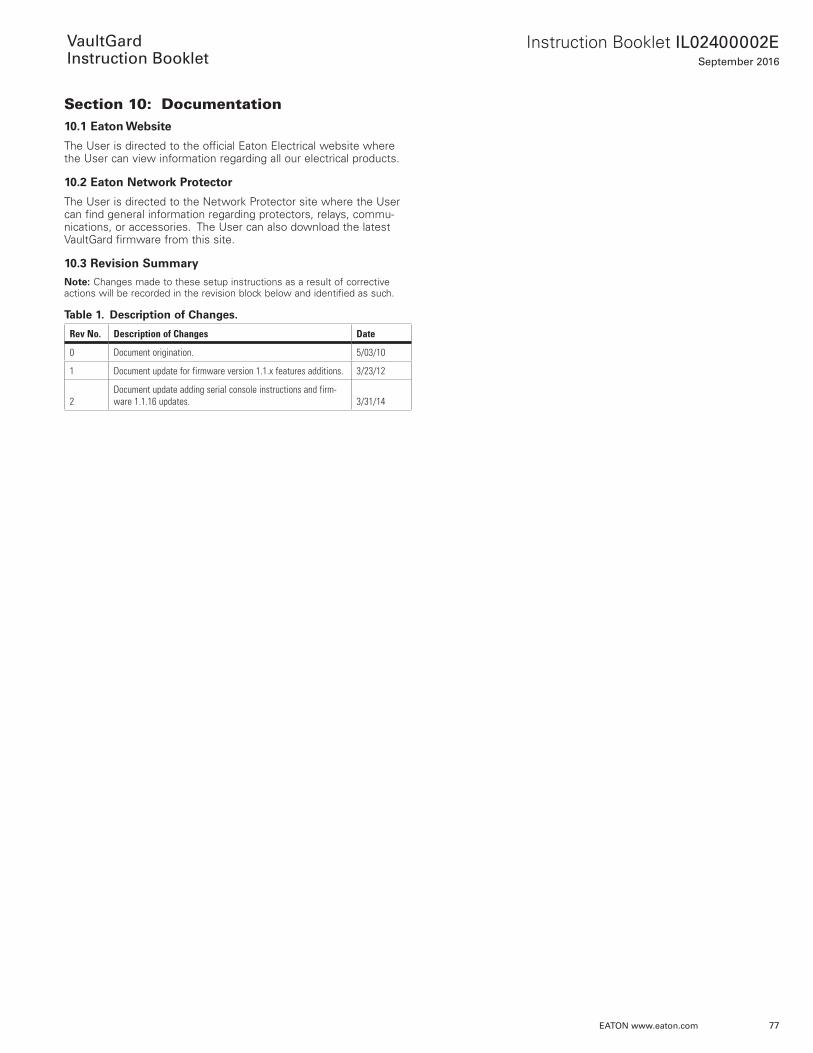
77
Instruction Booklet IL02400002ESeptember 2016
EATON www.eaton.com
VaultGard
Instruction Booklet
Section 10: Documentation10.1 Eaton Website
The User is directed to the official Eaton Electrical website where the User can view information regarding all our electrical products .
10.2 Eaton Network Protector
The User is directed to the Network Protector site where the User can find general information regarding protectors, relays, commu-nications, or accessories . The User can also download the latest VaultGard firmware from this site .
10.3 Revision Summary
ote:N Changes made to these setup instructions as a result of corrective actions will be recorded in the revision block below and identified as such .
Table 1. Description of Changes.
Rev No. Description of Changes Date
0 Document origination. 5/03/10
1 Document update for firmware version 1.1.x features additions. 3/23/12
2Document update adding serial console instructions and firm-ware 1.1.16 updates. 3/31/14

78
Instruction Booklet IL02400002ESeptember 2016
EATON www.eaton.com
VaultGard
Instruction Booklet
Notes:

79
Instruction Booklet IL02400002ESeptember 2016
EATON www.eaton.com
VaultGard
Instruction Booklet
Notes:
Instruction Booklet IL02400002ESeptember 2016
EatonElectrical Sector1000 Eaton BoulevardCleveland, OH 44122United States877-ETN-CARE (877)-386-2273 Eaton.com
© 2016 Eaton All Rights ReservedPrinted in USAPublication No. IL02400002E/ TBG000262September 2016
Eaton is a registered trademark.
All other trademarks are property of their respective owners.
VaultGard
Instruction Booklet
This instruction booklet is published solely for information purposes and should not be considered all-inclusive . If further information is required, you should consult an authorized Eaton sales representa-tive .
The sale of the product shown in this literature is subject to the terms and conditions outlined in appropriate Eaton selling policies or other contractual agreement between the parties . This literature is not intended to and does not enlarge or add to any such contract . The sole source governing the rights and remedies of any purchaser of this equipment is the contract between the purchaser and Eaton .
NO WARRANTIES, EXPRESSED OR IMPLIED, INCLUDING WARRANTIES OF FITNESS FOR A PARTICULAR PURPOSE OR MERCHANTABILITY, OR WARRANTIES ARISING FROM COURSE OF DEALING OR USAGE OF TRADE, ARE MADE REGARDING THE INFORMATION, RECOMMENDATIONS, AND DESCRIPTIONS CONTAINED HEREIN. In no event will Eaton be responsible to the purchaser or user in contract, in tort (including negligence), strict liability or otherwise for any special, indirect, incidental or conse-quential damage or loss whatsoever, including but not limited to damage or loss of use of equipment, plant or power system, cost of capital, loss of power, additional expenses in the use of existing power facilities, or claims against the purchaser or user by its cus-tomers resulting from the use of the information, recommendations and description contained herein .
In no event will Eaton be responsible to the user in contract, in tort (including negligence), strict liability or otherwise for any or loss whatsoever (whether direct or consequential)) resulting from the use of a 3rd party protocol and/or control protective relay .