Embed Size (px)
Citation preview

September, 2006 R. Dameron, University of Colorado, ECEN5033, System Test Planning
1
System Test Planningand the usefulness of a “Safety Checklist”
ECEN5543

September, 2006 R. Dameron, University of Colorado, ECEN5033, System Test Planning
2
Plan for class period• Additional notations to analyze requirements, prepare for
design and prepare for system test plan– Event tables– State transition tables– Decision tables (plus an old but useful shorthand), aka
condition tables
• Overview of system test categories• What to use to determine tests in each category
– Includes analysis of Safety Checklist with respect to stand-alone software
(Do Safety Checklist on use case as an experiment.)

September, 2006 R. Dameron, University of Colorado, ECEN5033, System Test Planning
3
More Requirements Analysis ToolsUseful for System Testing
Examples from Software Engineering Concepts, Richard Fairley, McGraw , Hill, 1985. Out of print.

September, 2006 R. Dameron, University of Colorado, ECEN5033, System Test Planning
4
System Sequence Diagram -- SSD
External actors interaction with system
Must define scope to know what is external
Actors can be other programs, other products, people
High Level view
Sequence diagrams are part of UML
Same rules used to create SYSTEM sequence diagrams

September, 2006 R. Dameron, University of Colorado, ECEN5033, System Test Planning
5
SSD

September, 2006 R. Dameron, University of Colorado, ECEN5033, System Test Planning
6
State Transition Table for “split” routine
Present State
Input Actions Outputs Next State
S0 DS Open F6
Open F7
S1
S1 D11 Write F6 D11; F6 S1
D12 Close F6
Write F7
D12; F7 S2
DE Close F6
Close F7
S0
S2 D12 Write F7 D12; F7 S2
DE Close F7 S0

September, 2006 R. Dameron, University of Colorado, ECEN5033, System Test Planning
7
Draw the state transition diagram for this state transition table
• Notation reminders:– Circle = state– Arc = transition– X/y = input/output

September, 2006 R. Dameron, University of Colorado, ECEN5033, System Test Planning
8
Present State Input or Event Action Output Next State
ST1. Idle card inserted request for PIN Waiting for PIN
ST2. Waiting for PINPIN entered display asterisks Validating PIN
ST3. Waiting for PINcancel display msg Ejecting
ST4. Validating PINindicates “valid” display choices Waiting for customer
transaction choice
ST5. Validating PINindicates “stolen” display “stolen” confiscating
ST6. Validating PINindicates “invalid” display “invalid” Waiting for PIN
ST7. Waiting for customer transaction choice Cancel display “cancel” Ejecting
ST8. Waiting for customer transaction choice Balance Query selected Processing query
continued on next slide

September, 2006 R. Dameron, University of Colorado, ECEN5033, System Test Planning
9
ST9. Waiting for customer transaction choice
Withdrawal selected Processing w/d
ST10. confiscating Card confiscated terminating
ST11. Processing query Rejected for this user display “rejected” Ejecting
ST12. Processing query Query OK display printing printing
ST13. Processing withdrawal ok amount display ok msg dispensing
ST14. Processing withdrawal not ok amount display refusal Ejecting
ST15. Printing transaction complete print receipt ejecting
ST16. Dispensing sufficient cash in ATM cash printing
ST17. Dispensing insufficient cash in ATM disp “insufficient cash”ejecting
ST18. Ejecting card ejection started display msg to
take card terminating
ST19. terminating card ejection complete display ending msg idle

September, 2006 R. Dameron, University of Colorado, ECEN5033, System Test Planning
10
State Transition Diagram - incomplete
Idle
card inserted/
waiting for PIN
PIN inserted/
validating PIN
ejecting
“cancel”“invalid”
“stolen”
confis-cating
“valid”
waiting for cust xaction
“cancel”
terminat-ing
card ej
complete
card confis’d

September, 2006 R. Dameron, University of Colorado, ECEN5033, System Test Planning
11
Notation:
Circle = action
Arc = data direction
Arc label = data
label = data sink
label = data source
= data store
Data flow diagram for “split”
splitDS D11* D12* DE
D11*
D12*
F6
F7

September, 2006 R. Dameron, University of Colorado, ECEN5033, System Test Planning
12
Data Flow Diagram for ATM
Validate User
ATM customer
card
request for pin
pin
validated user dispatch request
display transactions
transaction request

September, 2006 R. Dameron, University of Colorado, ECEN5033, System Test Planning
13
2-dimensional event tableEVENT
Mode E13 E37 E45 …
Start-up
A16 ---- A14; A32
Steady X A6, A2 ---
Shut-down
--- --- ---
Alarm --- --- ---
Action;action = sequential actions. Action, action = concurrent actions. X = impossible. --- = no action required.

September, 2006 R. Dameron, University of Colorado, ECEN5033, System Test Planning
14
Decision table1 2 3 4
Credit limit is satisfactory Y N N N
Pay experience is favorable -- Y N N
Special clearance obtained -- -- Y N
Perform the approve-order X X X
Reject order X
X = do that action; Y = yes, N = no, -- = don’t care
Act
ions
Con
diti
ons

September, 2006 R. Dameron, University of Colorado, ECEN5033, System Test Planning
15
Decision tables
• Ambiguous = two identical Rule columns with different actions
• Redundant = identical Rule columns and identical actions
• Incomplete = failure to specify an action for a Rule column
• Karnaugh map is more succinct

September, 2006 R. Dameron, University of Colorado, ECEN5033, System Test Planning
16
Incomplete and multiply-specifieddecision table as a Karnaugh map
A1
A2
A1
A2A2 A2
A1 A1 A3
C2 C3
C1
Example from Software Engineering Concepts, Richard Fairley, McGraw , Hill, 1985. Out of print.

September, 2006 R. Dameron, University of Colorado, ECEN5033, System Test Planning
17
Incomplete and multiply-specifieddecision table
A1
A2
A1
A2A2 A2
A1 A1 A3
C2 C3
C1
Example from Software Engineering Concepts, Richard Fairley, McGraw , Hill, 1985. Out of print.

September, 2006 R. Dameron, University of Colorado, ECEN5033, System Test Planning
18
Equivalent to this decision table:(incomplete and multiply-specified)
C1 Y d N
C2 d Y N
C3 d d Y
A1 X
A2 X
A3 X
Example from Software Engineering Concepts, Richard Fairley, McGraw , Hill, 1985. Out of print.

September, 2006 R. Dameron, University of Colorado, ECEN5033, System Test Planning
19
General Test Categories
• Functional
• Performance
• Stress
--------------------- not system test------------
• Glass-box, sometimes called white-box
September, 2006 R. Dameron, University of Colorado, ECEN5033, System Test Planning
20
Functional
• Success Scenario paths of Use Cases
• All alternate paths of Use Cases – if intentionally not implemented in a particular release, how is their absence handled?

September, 2006 R. Dameron, University of Colorado, ECEN5033, System Test Planning
21
Performance• Performance
– How does the system perform under normal conditions?
– Is it adequate?– “WHAT is performance” depends on application– Can be extended to include those quality ranges
that can be tested

22R. Dameron, University of Colorado, ECEN5033, System Test Planning
September, 2006
• How does system behave under unreasonable conditions?
• Evaluates robustness

September, 2006 R. Dameron, University of Colorado, ECEN5033, System Test Planning
23
Performance vs.
• Specified performance criteria are tested as performance tests (duh!)
• Unspecified performance criteria are tested as stress conditions
• Stress tests also include conditions outside the specified performance criteria

September, 2006 R. Dameron, University of Colorado, ECEN5033, System Test Planning
24
How do we decide what to test for performance and stress conditions?• Targeting Safety-Related Errors During
Software Requirements Analysis, Robyn R. Lutz, JPL, CalTech, Proceedings of the ACM SigSoft Symposium on the Foundations of Software Engineering, 1993
• The requirements discussed in the above paper provide excellent guidelines

September, 2006 R. Dameron, University of Colorado, ECEN5033, System Test Planning
25
Safety Checklist for safety-critical embedded systems
• Two most common causes of safety-related software errors– Inadequate interface requirements– Robustness issues -- discrepancies between
• The documented requirements • Requirements actually needed for correct
functioning
• Usage of the checklist reduces safety-related software errors

September, 2006 R. Dameron, University of Colorado, ECEN5033, System Test Planning
26
Earlier Study of Causes of S-R SW Errors – ref. 11 in the paper
• Errors identified as potentially hazardous to a system tend to be produced by different error mechanisms than non-safety-related software errors
• S-R sw errors found during integration & testing– Misunderstandings of sw’s interfaces to rest of sys
– Discrepancies between documented reqs & necessary requirements for correct functioning, i.e., robustness
– (In other words, the documented requirements are inadequate and therefore … wrong.)

September, 2006 R. Dameron, University of Colorado, ECEN5033, System Test Planning
27
What’s an error? A discrepancy between:• Computed• Observed• Measured value or
condition
• True• Specified• Theoretically correct
value or condition
Lutz: “Safety-related” if the systems safety analyst determines during standard error-correction process that the error represents potentially significant or catastrophic failure effects.

September, 2006 R. Dameron, University of Colorado, ECEN5033, System Test Planning
28
Effort to target known causes during requirements phase
• Interfaces Challenge: – Specify correctly the software/system interfaces in
complex embedded systems with software distributed among various hardware components – some of which are not yet determined
• Robustness Challenge:– Many s-r software errors involve inadequate software
responses to extreme conditions or extreme values (stress conditions)
– For “extreme”, read “boundary and beyond”

September, 2006 R. Dameron, University of Colorado, ECEN5033, System Test Planning
29
Formal vs. Informal• Lutz’ Safety Checklist is ok for a development
process without formal specification languages (whew!)
• And without (complete) finite-state-machine modeling
• DOES focus on software/system interfaces, failure modes, timing, and boundary conditions and values
Informal practices
Future formal analysis

September, 2006 R. Dameron, University of Colorado, ECEN5033, System Test Planning
30
2 key components of any sw requirements methodology
• To aid in determining the requirements
• To represent the software requirements in specifications
• This Safety Checklist focuses on first, still must incorporate in specification
• Determination technique does not preclude any specification techniques

September, 2006 R. Dameron, University of Colorado, ECEN5033, System Test Planning
31
NOTE: Benefit of Formal Inspections
• Example given is a formal inspection on 2,000,000 lines of code – seismic processing
• Can add the Safety Checklist to any other checklists being used in requirements reviews which are the first stage of system testing (prior to architecture design)

September, 2006 R. Dameron, University of Colorado, ECEN5033, System Test Planning
32
The Formal Approach
• Build a formal, finite-state model of the requirements specifications
• Analyze the model to ensure its properties match the desired behavior – State criteria (as formal predicates – logical
relationships) that must hold in the model

September, 2006 R. Dameron, University of Colorado, ECEN5033, System Test Planning
33
Lutz’ Less Formal Approach
• Translate the criteria into informal, natural-language format
• Formatting concerns as a checklist avoids need to build the complete finite-state model

September, 2006 R. Dameron, University of Colorado, ECEN5033, System Test Planning
34
Less Is More –Informal process extended to embedded systems
• Safety Checklist allows for– Multiple processors– Concurrently executing processes– Redundant resources to manage– Externally commanded state changes– State changes not visible
• Typical of many complex, embedded systems with timing constraints and safety-critical functions
• Even in stand-alone system, can have operating system environment, “apparent concurrency”, externally commanded state changes, invisible state changes

September, 2006 R. Dameron, University of Colorado, ECEN5033, System Test Planning
35
Checklist regarding Interfaces

September, 2006 R. Dameron, University of Colorado, ECEN5033, System Test Planning
36
Interfaces – Is the software’s response specified:
1. For every input, what is the response to out-of-range values?
2. For not receiving an expected input ? If appropriate to time out – a. length, b. when
to start counting, c. latency
3. If input arrives when it shouldn’t
4. On given input, will software always follow the same path? (deterministic)
If not, is that a problem?

September, 2006 R. Dameron, University of Colorado, ECEN5033, System Test Planning
37
Interfaces, continued
5. Is each input bounded in time? Specify earliest time to accept input Latest time to consider data to be valid
6. Is minimum and maximum arrival rate specified for each input? For each communication path?
7. If interrupts are masked or disabled, can events be lost?
• Include cooperating processes in “apparent concurrency”

September, 2006 R. Dameron, University of Colorado, ECEN5033, System Test Planning
38
Interfaces, continued 2
8. Can output be produced faster than it can be used (absorbed) by the interfacing module? Is overload behavior specified?
9. Is all data output [to the buses from the sensors] used by the software? If not, is some required function omitted from the spec?
10. Can input received before startup, while offline, or after shutdown influence the next software startup behavior? Are any values retained in hw or sw? The earliest? The most recent?

September, 2006 R. Dameron, University of Colorado, ECEN5033, System Test Planning
39
Checklist regarding Robustness

September, 2006 R. Dameron, University of Colorado, ECEN5033, System Test Planning
40
Robustness
11. If performance degradation is the chosen response, is the degradation predictable?
12. Are there sufficient delays incorporated into the error-recovery responses, e.g. don’t return to normal state prior to managing the error
13. Are feedback loops specified where appropriate to compare the actual effects of outputs on the system with the predicted effects?

September, 2006 R. Dameron, University of Colorado, ECEN5033, System Test Planning
41
Robustness, continued
14. Are all modes and modules reachable (used in some path through the code)? Superfluous? Other logic error?
15. If a hazards analysis has been done, does every path from a hazardous state (a failure-mode) lead to a low-risk state?
16. Are the inputs identified which, if not received, can lead to a hazardous state or can prevent recovery (single-point failures)?

September, 2006 R. Dameron, University of Colorado, ECEN5033, System Test Planning
42
Usefulness?
• Safety checklist has been demonstrated to “ask the right questions”
• Not sufficient to preclude introducing errors
• Necessary although not sufficient

September, 2006 R. Dameron, University of Colorado, ECEN5033, System Test Planning
43
May I have the envelope, please … Not every hazardous state led to a low-risk state.
Error-recovery responses incorporated
insufficient delays.
Input arrived when it shouldn’t and no response
was specified; response defaulted to
unintended behavior.
Response not specified for out-of-range values
that were possible for some inputs
#5 Output produced too fast for interfacing module
#4
#2
#3
#1

September, 2006 R. Dameron, University of Colorado, ECEN5033, System Test Planning
44
Allows tailoring
• Focuses on historically troublesome aspects of safety-critical, embedded software
• Avoids over-specification of well-understood or low-risk requirements
• Tailor to level of technical or historical risk

September, 2006 R. Dameron, University of Colorado, ECEN5033, System Test Planning
45
First step toward safety constraints
• Many items that it identifies are system hazards
• Can be used to identify safety constraints
• Not yet ready for formal prediction– How use for informal prediction of error prone
factors

September, 2006 R. Dameron, University of Colorado, ECEN5033, System Test Planning
46
After Requirements Are Improved …
• How do we ensure that requirements are implemented and maintained?– After code is written (new code or bug fixes);
note: difficult to unit test these issues– After new requirements are added– After old requirements are modified
• Role of reviews• Code the invariants where appropriate• System tests to test use cases and the safety
checklist

September, 2006 R. Dameron, University of Colorado, ECEN5033, System Test Planning
47
Create a system test plan – IEEE Std. 829
1. Test the Success Scenario and conditions that lead to alternative paths of use cases
2. If possible, test to verify the relevant safety checklist items – “safety” may not be main concern but correct interfaces and robustness are.
3. If any resources are shared among processes, review and test for correctness of mutual exclusion. (SW Eng of Multi-program Sys)
4. If “cooperating processes”, verify suspension happens correctly, a suspended process restored when appropriate, restoration correct.

September, 2006 R. Dameron, University of Colorado, ECEN5033, System Test Planning
48
IEEE 829 Standard Test Plan Outline - 11.0 Introduction
2.0 Test Items
3.0 Tested Features
4.0 Features Not Tested (per cycle)
[Repeat 5.0 for each system level test.]
5.0 Testing Strategy and Approach
5.1 Syntax
5.2 Description of functionality
5.3 Arguments for Test
5.4 Expected Output
5.5 Specific Exclusions
5.6 Dependencies
5.7 Test Case Success/Failure Criteria
September, 2006 R. Dameron, University of Colorado, ECEN5033, System Test Planning
49
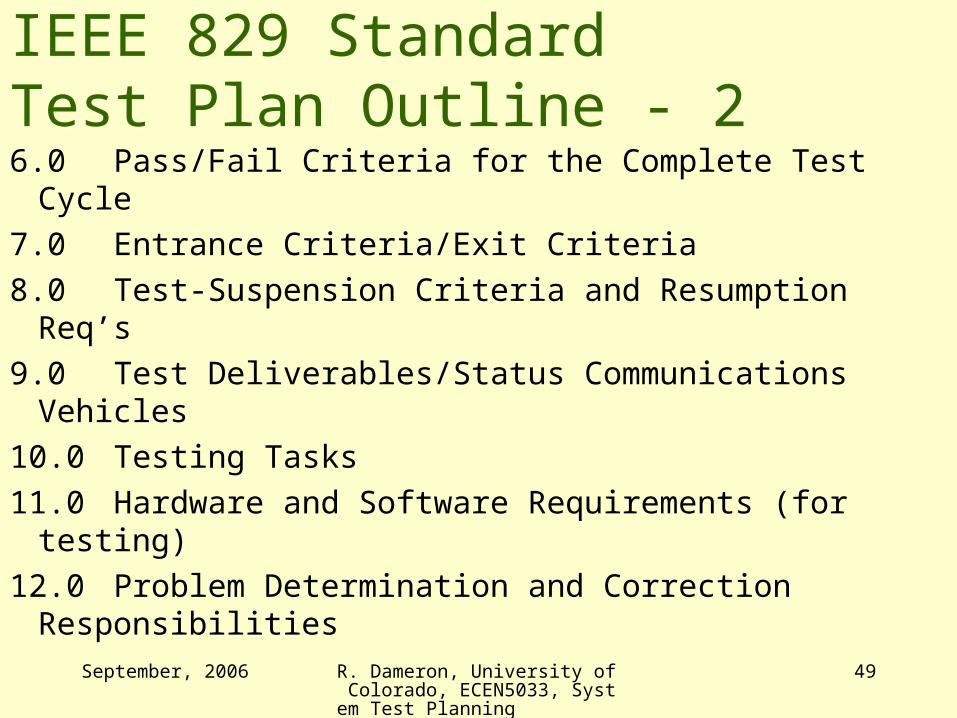
IEEE 829 Standard Test Plan Outline - 26.0 Pass/Fail Criteria for the Complete Test Cycle
7.0 Entrance Criteria/Exit Criteria
8.0 Test-Suspension Criteria and Resumption Req’s
9.0 Test Deliverables/Status Communications Vehicles
10.0 Testing Tasks
11.0 Hardware and Software Requirements (for testing)
12.0 Problem Determination and Correction Responsibilities

September, 2006 R. Dameron, University of Colorado, ECEN5033, System Test Planning
50
IEEE 829 Standard Test Plan outline - 3
13.0 Staffing and Training Needs/Assignments
14.0 Test Schedules
15.0 Risks and Contingencies
16.0 Approvals

September, 2006 R. Dameron, University of Colorado, ECEN5033, System Test Planning
51
Glass-box – briefly (Need implementation details)
• Test module/process/object-cluster interfaces (process level can be system test)
• Test object/object-cluster contracts
• Create test data to force certain code paths
• Note: if team is doing incremental development, you can begin glass-box testing early

September, 2006 R. Dameron, University of Colorado, ECEN5033, System Test Planning
52
More to consider
• If the system is too large to test thoroughly, what tests should you emphasize?
• Stay tuned …


![jazzpotes2.free.frjazzpotes2.free.fr/AEBERSOLD/Aebersold - Vol 99 - [Tadd Dameron].pdf · CD VOLUME 99 Enclosed Tadd Dameron Book and ŒL) Set I n strum entali Sts](https://img.dokumen.tips/doc/110x75/5b3891c87f8b9a5a178d8808/-vol-99-tadd-dameronpdf-cd-volume-99-enclosed-tadd-dameron-book-and-oel.jpg)


