Embed Size (px)
Citation preview
Separation Control with Nanosecond Pulse Driven Dielectric Barrier Discharge Plasma Actuators
Lucio Cota Advisor: Jesse Little
Department of Aerospace and Mechanical EngineeringUniversity of Arizona
Arizona Space Grant Consortium SymposiumApril 12th, 2014
Tucson, AZ

IntroductionFlow Separation in Aerodynamics• Decreases Lift• Increases Drag
Separated Flow Partially Attached Flow via Plasma Actuation
2
Caraballo et al, 2014

Dielectric Barrier Discharge (DBD) Plasma Actuator
• Two Copper Electrodes separated by a dielectric (Kapton tape)
• Creates plasma when high voltage is applied (10 kV)
3

Nanosecond (ns) - DBD• Plasma actuation causes a
compression wave due to rapid localized heating
• Re-energizes the flow for control separation
• Effects are dependent on driving voltage and frequency of pulses
4

Objectives• Compare positive and negative polarity driving
voltages for flow control authority• Previous research shows negative polarity
generates stronger pressure waves in quiescent air (Dawson et al, 2013)
5
Positive Negative
6
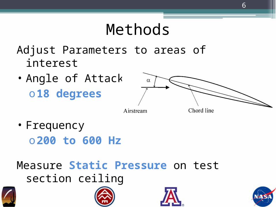
MethodsAdjust Parameters to areas of interest• Angle of Attack (α)o18 degrees
• Frequencyo200 to 600 Hz
Measure Static Pressure on test section ceiling
6

Experimental Facilities• Adjustable wall plugs to control Angle of Attack• Ceiling pressure taps to measure Static Pressure
7

Experimental Facilities• Adjustable wall plugs to control Angle of Attack• Ceiling pressure taps to measure Static Pressure
7

Coefficient of Pressure (Cp) Interpretation
Pressure ↓ Velocity ↑
Without Plasma With PlasmaHigh Velocity Region
Caraballo et al, 2014
8

Pressure Distribution: 200 Hz
NACA0015, Re = 1.12 x 10⁵ , α = 18°
- Positive and Negative Polarity are near equal at leading edge
9

Pressure Distribution: 400 Hz
NACA0015, Re = 1.12 x 10⁵ , α = 18°
- Negative Polarity is more negative than Positive
10

Pressure Distribution: 600 Hz
11
- Positive Polarity behaves similar to Baseline, Negative still effective
NACA0015, Re = 1.12 x 10⁵ , α = 18°

Summary200 Hz• Positive discharges and Negative discharges have
the same effectiveness at the leading edge400 Hz• Greatest effect from Negative Discharges600 Hz• Positive Discharge performs similar to baseline• Effect by Negative Discharges still present
12

Conclusion• Both Polarities perform best at low frequencies
(preferred frequencies exist)• Positive Discharges, at its preferred frequency,
has the same influence on Flow Control as Negative Discharges and little to no effect at higher frequencies
• Negative Discharges show an effect at all frequencies
• Investigation of input voltage may provide more conclusions
13

This Research was Sponsored by• Arizona Space Grant Consortium• Air Force Office of Scientific Research
Special Thanks to• UA Department of Aerospace and Mechanical Engineering• Robyn Dawson• Everyone on the Research Team
14
Acknowledgements

16
Thank You
15

ReferencesCaraballo, E., T. Sullivan, R. You, and J. Little. "Characterization of the Flow Field over a
NACA 0015 Airfoil Using Stochastic Estimation Based on Surface Pressure and Hot Film Measurements." AIAA SciTech 13-17.January (2014)
Dawson, Robert, and Jesse Little. "Characterization of Nanosecond Pulse Driven Dielectric Barrier Discharge Plasma Actuators for Aerodynamic Flow Control." Journal of Applied Physics 113.10 (2013): 103302. Print.
16

18
Pulse Generator• Generates pulses by magnetic compression
17