Embed Size (px)
Citation preview
INSTALLATION AND OPERATION SX TRANSISTOR CONTROL Page 1
April 2002
SEPARATELY EXCITED (SX) TRANSISTORIZED MOTOR CONTROLLERS
FOR NEIGHBORHOOD ELECTRIC VEHICLE APPLICATION
INSTALLATION AND OPERATION MANUAL
(GE MODEL IC3645SH7R354D2)
Note: The information contained herein is intended to assist OEM's, Dealers and Users of electric vehicles in the application, installation and service of GE solid-state controllers. This manual does not purport to cover all variations in OEM vehicle types. Nor does it provide for every possible contingency to be met involving vehicle installation, operation or maintenance. For additional information and/or problem resolution, please refer the matter to the OEM vehicle manufacturer through his normal field service channels. Do not contact GE directly for this assistance.
General Electric Company April 2002
Section 1.0 INTRODUCTION ........................................................................................................................................................ 3 1.1 Motor Characteristics .............................................................................................................. 3 1.2 Solid-State Reversing............................................................................................................... 4 1.3 Flexible System Application..................................................................................................... 4 1.4 More Features with Fewer Components ................................................................................ 4 Section 2.0 FEATURES OF SX FAMILY OF MOTOR CONTROLLERS .................................................................................... 5 2.1 Performance.............................................................................................................................. 5
2.1.1 Oscillator Card Features .................................................................................................. 5 2.1.1.a Standard Operation............................................................................. ...................... 5 2.1.1.b Control Acceleration ................................................................................................ 5 2.1.2 Current Limit ...................................................................................................................... 5 2.1.3 Plug Braking ...................................................................................................................... 5 2.1.4 Regenerative Braking to Base Speed............................................................................. 5 2.1.5 Auxiliary Speed Control.................................................................................................... 5 2.1.5.a Field Weakening........................................................................................................ 5 2.1.5.b Speed Limits .............................................................................................................. 5 2.1.5.c Top Speed Regulation ........................................................................ ............ ......... 6 2.1.6 Ramp Start ......................................................................................................................... 6 2.1.7 On-Board Coil Drivers and Internal Coil Suppression ................................................. 6
Table of Contents
INSTALLATION AND OPERATION SX TRANSISTOR CONTROL Page 2
April 2002
2.2 System Protective Override ..................................................................................................... 6 2.2.1 Start Switch Check .......................................................................................................... 6 2.2.2 Accelerator Volts Hold Off ............................................................................................... 6 2.2.3 Pulse Monitor Trip (PMT)................................................................................................. 6 2.2.4 Thermal Protector (TP)................................... .................................................................. 6 2.2.5 Low Voltage .................................... .................................................................................. 6 2.3 Diagnostics................................................ ................................................................................ 6 2.3.1 Status Codes...................................................................................................................... 6 2.3.1.a Standard Status Codes............................................................................................. 6 2.3.1.b Stored Status Codes ......................................... ....................................................... 7 2.3.2 Hourmeter Readings ...................................... .................................................................. 7 2.3.3 Dash Display Routine and Battery Discharge Indication (BDI)....................... ........... 7 2.3.4 Internal Resistance Compensation ..................... ........................................................... 7 2.3.5 Handset ................................................. ............................................................................ 7 2.3.6 RS-232 Communication Port ............................... ............................................................ 7 2.3.7 Circuit Board Coil Driver Modules........................ .......................................................... 7 Section 3.0 ORDERING INFORMATION, ELEMENTARY AND OUTLINE DRAWINGS...................................................... 8 3.1 Ordering Information for Separately Excited Controls......................................................... 8 3.2 Outline: SX-2 Package Size...................................................................................................... 9 3.3 Standard Elementary for NEV Application ............................................................................ 10 3.4 Standard NEV Application Input/Output List......................................................................... 11 Section 4.0 TROUBLESHOOTING AND DIAGNOSTIC STATUS CODES.............................................................................. 12
4.1 General Maintenance Instructions................................................................................................. 12
4.2 Cable Routing and Separation ............................................................................................... 12 4.2.1 Application Responsibility ............................................................................................... 12 4.2.2 Signal/Power Level Definitions ............................................................................................... 12 4.2.2.a Low Level Signals (Level L) .............................................................................................. 12
4.2.2.b High Level Signals (Level H)............................................................................................. 13 4.2.2.c Medium-Power Signals (Level MP) ................................................................................ 13 4.2.2.d High-Power Signals (Level HP) ....................................................................................... 13
4.2.3 Cable Spacing Guidelines ........................................................................................................ 13 4.2.3.a General Cable Spacing..................................................................................................... 13 4.2.4 Cabling for Vehicle Retrofits.................................................................................................... 13 4.2.5 RF Interference.......................................................................................................................... 13 4.2.6 Suppression............................................................................................................................... 13
4.3 Recommended Lubrication of Pins and Sockets Prior to Installation........................................ 14 4.4 General Troubleshooting Instructions ........................................................................................... 15
4.5 Traction Controller Status Codes ................................................................................................... 16-28
Section 5.0 SX FAMILY - GE HANDSET INSTRUCTIONS ...................................................................................................... 29 5.1 General Features ...................................................................................................................... 29 5.2 Purpose/Setup Functions ........................................................................................................ 29 5.3 Setup Function Procedures ................................ .................................................................... 30 5.3.1 Setup Mode ............................................ .......................................................................... 30 5.3.2 Status Code Scrolling.................................. ..................................................................... 30 5.3.3 SX Handset Plug Connections and Outline Drawing................ .................................... 30 5.4 Setup Functions for Traction Controller ................................................................................ 31-35 5.5 Summary of Current Limit Adjustments.................................................................................. 36 Section 6.0 MEMORY MAP................................................. ......................................................................................................... 37-39
Table of Contents ( Continued )
BASIC OPERATION AND FEATURES SX TRANSISTOR CONTROL Page 3
April 2002
Section 1. INTRODUCTION
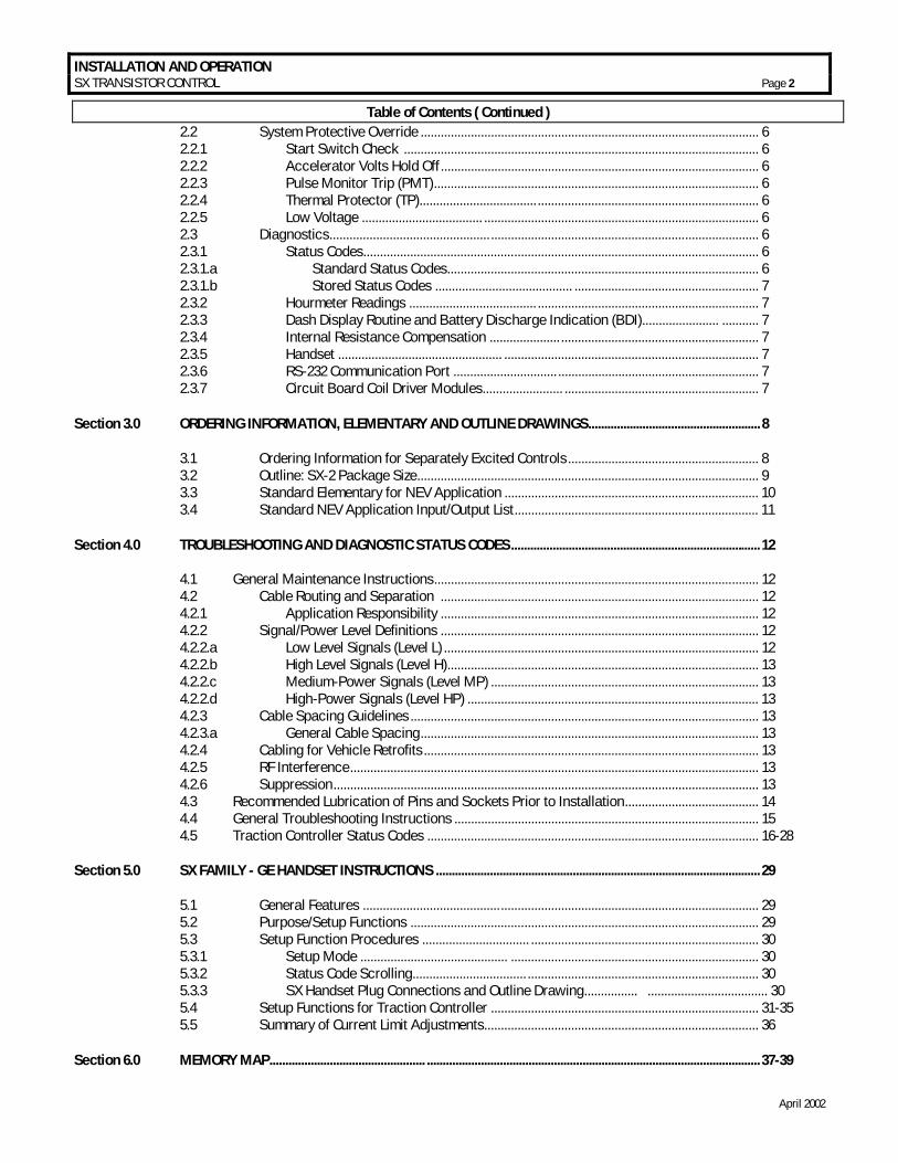
Section 1.1 Motor Characteristics The level of sophistication in the controllability of traction motors has changed greatly over the past several years. Vehicle manufacturers and users are continuing to expect more value and flexibility in electric vehicle motor and control systems as they are applied today. In order to respond to these market demands, traction system designers have been forced to develop new approaches to reduce cost and improve functions and features of the overall system. Development is being done in a multi-generational format that allows the market to take advantage of today’s technology, while looking forward to new advances on the horizon. GE has introduced a second generation system using separately excited DC shunt wound motors. The separately excited DC motor system offers many of the features that are generally found on the advanced AC systems. Historically, most electric vehicles have relied on series motor designs because of their ability to produce very high levels of torque at low speeds. But, as the demand for high efficiency systems increases, i.e., systems that are more closely applied to customers’ specific torque requirements, shunt motors are now often being considered over series motors. In most applications, by independently controlling the field and armature currents in the separately excited motor, the best attributes of both the series and the shunt wound motors can be combined.
NO LO
AD CU
RREN
T
FULL
LOAD
CURR
ENT
STAR
TING
CURR
ENT
ARMATURE CURRENTFigure 1
SPEED
TORQUE
As shown in the typical performance curves of Figure 1, the high torque at low speed characteristic of the series motor is evident. In a shunt motor, the field is connected directly across the voltage source and is therefore independent of variations in load and armature current. If field strength is held constant, the torque developed will vary directly with the armature current. If the mechanical load on the motor increases, the motor slows down, reducing the back EMF (which depends on the speed, as well as the constant field strength). The reduced back EMF allows the armature
current to increase, providing the greater torque needed to drive the increased mechanical load. If the mechanical load is decreased, the process reverses. The motor speed and the back EMF increase, while the armature current and the torque developed decrease. Thus, whenever the load changes, the speed changes also, until the motor is again in electrical balance. In a shunt motor, the variation of speed from no load to normal full load on level ground is less than 10%. For this reason, shunt motors are considered to be constant speed motors (Figure 2).
NO
LOAD
CURR
ENT
FULL
LOAD
CURR
ENT
STAR
TING
CURR
ENT
ARMATURE CURRENTFigure 2
SPEED
TORQUE
In the separately excited motor, the motor is operated as a fixed field shunt motor in the normal running range. However, when additional torque is required, for example, to climb non-level terrain, such as ramps and the like, the field current is increased to provide the higher level of torque. In most cases, the armature to field ampere turn ratio can be very similar to that of a comparable size series motor (Figure 3.)
NO LO
AD CU
RREN
T FULL
LOAD
CURR
ENT
STAR
TING
CURR
ENT
ARMATURE CURRENTFigure 3
SPEED
TORQUE
Aside from the constant horsepower characteristics described above, there are many other features that provide increased performance and lower cost. The following description provides a brief introduction to some of these features.
BASIC OPERATION AND FEATURES SX TRANSISTOR CONTROL Page 4
April 2002
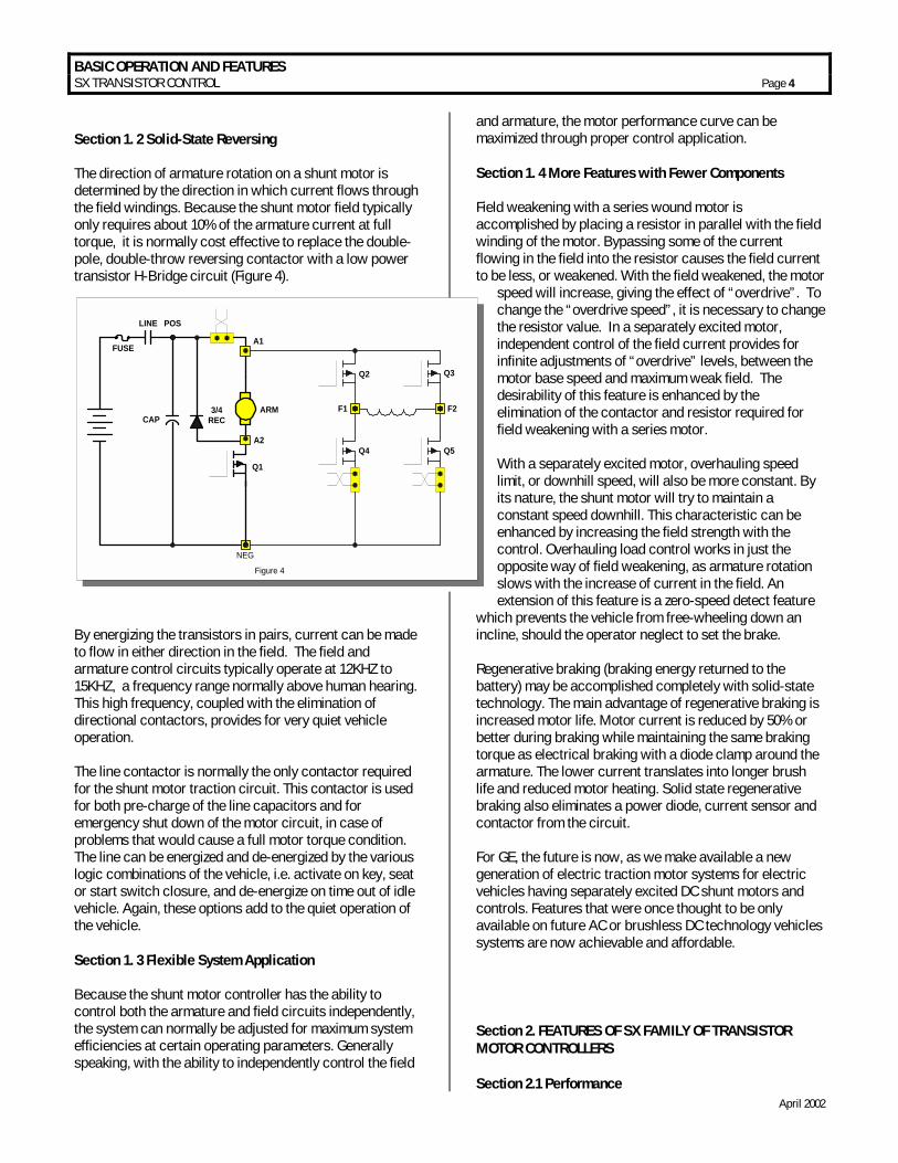
Section 1. 2 Solid-State Reversing The direction of armature rotation on a shunt motor is determined by the direction in which current flows through the field windings. Because the shunt motor field typically only requires about 10% of the armature current at full torque, it is normally cost effective to replace the double-pole, double-throw reversing contactor with a low power transistor H-Bridge circuit (Figure 4).
By energizing the transistors in pairs, current can be made to flow in either direction in the field. The field and armature control circuits typically operate at 12KHZ to 15KHZ, a frequency range normally above human hearing. This high frequency, coupled with the elimination of directional contactors, provides for very quiet vehicle operation. The line contactor is normally the only contactor required for the shunt motor traction circuit. This contactor is used for both pre-charge of the line capacitors and for emergency shut down of the motor circuit, in case of problems that would cause a full motor torque condition. The line can be energized and de-energized by the various logic combinations of the vehicle, i.e. activate on key, seat or start switch closure, and de-energize on time out of idle vehicle. Again, these options add to the quiet operation of the vehicle. Section 1. 3 Flexible System Application Because the shunt motor controller has the ability to control both the armature and field circuits independently, the system can normally be adjusted for maximum system efficiencies at certain operating parameters. Generally speaking, with the ability to independently control the field
and armature, the motor performance curve can be maximized through proper control application. Section 1. 4 More Features with Fewer Components Field weakening with a series wound motor is accomplished by placing a resistor in parallel with the field winding of the motor. Bypassing some of the current flowing in the field into the resistor causes the field current to be less, or weakened. With the field weakened, the motor
speed will increase, giving the effect of “overdrive”. To change the “overdrive speed”, it is necessary to change the resistor value. In a separately excited motor, independent control of the field current provides for infinite adjustments of “overdrive” levels, between the motor base speed and maximum weak field. The desirability of this feature is enhanced by the elimination of the contactor and resistor required for field weakening with a series motor. With a separately excited motor, overhauling speed limit, or downhill speed, will also be more constant. By its nature, the shunt motor will try to maintain a constant speed downhill. This characteristic can be enhanced by increasing the field strength with the control. Overhauling load control works in just the opposite way of field weakening, as armature rotation slows with the increase of current in the field. An extension of this feature is a zero-speed detect feature
which prevents the vehicle from free-wheeling down an incline, should the operator neglect to set the brake. Regenerative braking (braking energy returned to the battery) may be accomplished completely with solid-state technology. The main advantage of regenerative braking is increased motor life. Motor current is reduced by 50% or better during braking while maintaining the same braking torque as electrical braking with a diode clamp around the armature. The lower current translates into longer brush life and reduced motor heating. Solid state regenerative braking also eliminates a power diode, current sensor and contactor from the circuit. For GE, the future is now, as we make available a new generation of electric traction motor systems for electric vehicles having separately excited DC shunt motors and controls. Features that were once thought to be only available on future AC or brushless DC technology vehicles systems are now achievable and affordable. Section 2. FEATURES OF SX FAMILY OF TRANSISTOR MOTOR CONTROLLERS Section 2.1 Performance
FUSE
LINE
3/4RECCAP
ARM F2F1
Q2
Q4
Q3
Q5
Q1
POS
NEG
Figure 4
A1
A2
BASIC OPERATION AND FEATURES SX TRANSISTOR CONTROL Page 5
April 2002
Section 2.1.1 Oscillator Card Features Section 2.1.1.a Standard Operation The oscillator section of the card has two adjustable features, creep speed and minimum field current. With the accelerator at maximum ohms or volts, the creep speed can be adjusted by Function 2 of the Handset or a trimpot. The field control section allows the adjustment of the field weakening level in order to set the top speed of the motor. This top speed function (Minimum Field Current) is enabled when the armature current is less than the value set by Function 24 and the accelerator input voltage is less than 1 volt. Top Speed can be adjusted by Function 7 of the Handset or a trimpot. The % ON-time has a range of approximately 0 to 100 percent. The SX controllers operate at a constant frequency and the % ON-time is controlled by the pulse width of the voltage/current applied to the motor circuits. Section 2.1.1.b Control Acceleration This feature allows for adjustment of the rate of time it takes for the control to accelerate to 100% applied battery voltage to the motor on hard acceleration. Armature C/A is adjusted by Function 3 from 0.1 to 22 seconds. Section 2.1.2 Current Limit This circuit monitors motor current by utilizing sensors in series with the armature and field windings. The information detected by the sensor is fed back to the card so that current may be limited to a preset value. If heavy load currents are detected, this circuit overrides the oscillator and limits the average current to a value set by Function 4 and Function 8 of the Handset. The C/L setting is based on the maximum thermal rating of the control. Because of the flyback current through 3REC, the motor current is usually greater than battery current, except at 100% ON time. Section 2.1.3 Plug Braking Slow down is accomplished when reversing direction by providing a small amount of retarding torque for deceleration. If the vehicle is moving, and the directional lever is moved from one direction to the other, the plug signal is initiated. Once the plug signal has been initiated, the field is reversed, and the armature current is regulated to the plug current limit. Armature current is regulated by increasing the field current as the vehicle slows down. Once the field current reaches a preset value, set by Function 10, and armature plug current can no longer be maintained, the braking function is canceled, and the control reverts back to motoring.
All energy produced by the motor during plugging is dumped as heat in the motor in this braking mode. Section 2.1.4 Regenerative Braking to Base Speed Regenerative braking to base speed is a function of the vehicle motor design which slows the vehicle to a speed corresponding to the base speed of the motor whenever the start switch is opened or the control detects an overspeed condition. The field FETs pulse on/off to regulate the armature current. During regen, armature current is allowed to flow from the armature through the current sensor, the battery, the armature transistor and back to the armature. All regen current is returned to the battery. Regen current will continue to flow until the speed of the motor drops below its base speed, at which point the vehicle will coast. Section 2.1.5 Auxiliary Speed Control Section 2.1.5.a Field Weakening This function allows the adjustment of the field weakening level in order to set the top speed of the motor. The function is enabled when the armature current is less than the value set by Function 24. It is important to note that this function is used to optimize motor and control performance, and this setting will be determined by GE and OEM engineers at the time of vehicle development. This setting must not be changed by field personnel without the permission of the OEM. Section 2.1.5.b Speed Limits This feature provides a means to limit motor speed by controlling the armature voltage. The speed limit setting provides a clamp on the accelerator voltage command, limiting the conduction period of the armature FET’s. There are two speed limit settings, reverse speed limit and turf speed limit. When the reverse direction is selected, pin 5 is high, and the reverse speed limit will be used and the turf switch is not checked by software. When the forward direction is selected, pin 4 is high. The turf speed limit will be enabled if the turf speed switch input, pin 6, is low. The voltage to the motor armature will vary as a function of the speed limit settings and the battery volts. The motor speed will vary as a function of load and battery volts. Section 2.1.5.c Top Speed Regulation This feature requires a system tachometer. The standard GE system tach is built into the motor and provides four pulses per armature revolution. Once the control has been calibrated to the vehicle parameters (gear ratio and wheel rolling radius), using Function 1, speed can be measured with a resolution of +/- 1 mph. When traveling
BASIC OPERATION AND FEATURES SX TRANSISTOR CONTROL Page 6
April 2002
down an incline, if the vehicle speed increases to the over speed setting, the control automatically transitions to the regen mode. The maximum incline on which the control will be able to maintain regulation is determined by the characteristics of the motor, the maximum regen armature current limit setting (Function 9), and the maximum regen field current limit setting (Function 10). When the vehicle reaches the bottom of the incline, and the vehicle speed decreases below the over speed setting on the level surface, the control automatically transitions back to the normal running mode. Section 2.1.6 Ramp Start This feature provides maximum control torque to restart a vehicle on an incline. The memory for this function is the directional switch. When stopping on an incline, the directional switch must be left in its original or neutral position to allow the control to initiate full power when restarted. The accelerator potentiometer input will modulate ramp start current. Section 2.1.7 On-Board Coil Drivers and Internal Coil Suppression A coil driver for the LINE contactor is on-board the control card. This contactor must have a coil rated for the vehicle battery volts, with a maximum current of 1 amp. Section 2.2 System Protective Override Section 2.2.1 Start Switch Check If the key switch is opened, the control shuts off and cannot be restarted until the start switch opens (see Status Code –11, described in Section 4.5 of this manual). Section 2.2.2 Accelerator Volts Hold Off This feature checks the voltage level at the accelerator input whenever the key switch is activated. If, at key on, the voltage is greater than 1.24 volts, the control will not operate. This feature assures that the control is calling for low speed operation at start up (see Status Code –8, described in Section 4.5 of this manual). Section 2.2.3 Pulse Monitor Trip (PMT) The PMT design contains three features which shut down, or lock out, control operation if a fault conditions occurs that would cause a disruption of normal vehicle operation: • = Look ahead • = Look again • = Automatic look again and reset
The PMT circuit will not allow the control to start under the following conditions: • = The control monitors armature FET's at start-up and
during running. • = The control will not allow the line contactor to close at
start-up, or will drop it out during running, if the armature FET's are of low resistance, so as to cause uncontrolled vehicle movement.
Section 2.2.4 Thermal Protector (TP) This temperature sensitive device is internal to the power transistor (Q1) module. If the transistor's temperature begins to exceed the design limits, the thermal protector will lower the maximum current limit, and maintain the transistors within their temperature limits. As the control cools, the thermal protector will automatically reset, returning the control to full power. Section 2.2.5 Low Voltage Batteries under load, particularly if undersized or more than 80 percent discharged, will produce low voltages at the control terminals. The SX control is designed for use down to 50 percent of a nominal battery voltage of 36-84 volts, and 75 percent of a nominal battery voltage of 24 volts. Lower battery voltage may cause the control to operate improperly, however, the resulting PMT should open the Line contactor, in the event of a failure. Section 2.3 Diagnostics The control detects the system's present operating status and this status can be displayed to either the Dash Display or the Handset. Section 2.3.1 Status Codes Section 2.3.1a Standard Status Codes The SX control has a wide variety of Status Codes that assist the service technician and operator in trouble shooting the vehicle. If mis-operation of the vehicle occurs, a status code will be displayed on the Dash Display for vehicles so equipped, or be available from the status code displayed when the Handset is plugged into the “Y” plug of the logic card. With the status code number, follow the procedures outlined in DIAGNOSTIC STATUS CODES to determine the problem and appropriate corrective action. Note: The Status Code Instruction Sheets do not purport to cover all possible causes of a display of a "status code ". They do provide instructions for checking the most direct inputs that can cause status codes to appear.
BASIC OPERATION AND FEATURES SX TRANSISTOR CONTROL Page 7
April 2002
Section 2.3.1.b Stored Status Codes This feature records the last 16 "Stored Status Codes" that have caused a PMT controller shut down and/or disrupted normal vehicle operation. (PMT type faults are reset by cycling the key switch). These status codes, along with the corresponding BDI and hourmeter readings, can be accessed with the Handset, or by using the RS 232 communications port and dumping the information to a Personal Computer terminal. Section 2.3.2 Hourmeter Readings This feature will display the recorded hours of use of the traction control to the Dash Display (if used) each time the key switch is turned off. Section 2.3.3 Dash Display Routine and Battery Discharge Indication (BDI) The latest in microprocessor technology is used to provide accurate battery state of charge information and to supply passive and active warning signals to the vehicle operator. The control outputs a signal for dash display to display the vehicle speed in MPH once every 0.1 seconds for 9.5 seconds. After that point, the dash display shows the battery discharge indicator value once. Section 2.3.4 Internal Resistance Compensation This feature is used when the Battery Discharge Indicator is present. Adjustment of this function will improve the accuracy of the BDI. Section 2.3.5 Handset This is a multi-functional tool used with the LX, ZX, and SX Series GE solid state controls. The Handset consists of a Light Emitting Diode (LED) display and a keyboard for data entry. Features and functions: • = Monitor existing system status codes for traction
controls. Monitor intermittent random status codes. • = Monitor battery state of charge, if available.
• = Monitor hour meter reading on traction controls. Monitor or adjust the control functions.
Section 2.3.6 RS 232 Communication Port This serial communication port displays the vehicle speed in MPH nine times, and then flashes a Status Code –90, once, if the motor is overheating. Refer to Section 4.5 of this manual, for additional description of Status Code –90. If the motor is not overheating, the BDI value will be displayed once, in place of Status Code –90 output. The serial port also provides service personnel with access to operating information and control settings via a personal computer. Section 2.3.7 Circuit Board Coil Driver Modules Coil drivers are internal to the control card, and are the power devices that operate the Line contactor coils. On command from the control card, these drivers initiate opening and closing the contactor coils. All driver modules are equipped with reverse battery protection, such that, if the battery is connected incorrectly, the contactors cannot be closed electrically.
OUTLINE DRAWINGS, ELEMENTARY DRAWINGS AND INPUTS/OUTPUTS SX TRANSISTOR CONTROL Page 8
April 2002
Section 3.0 ORDERING INFORMATION, ELEMENTARY AND OUTLINE DRAWINGS Section 3.1 Ordering Information for Separately Excited Controls
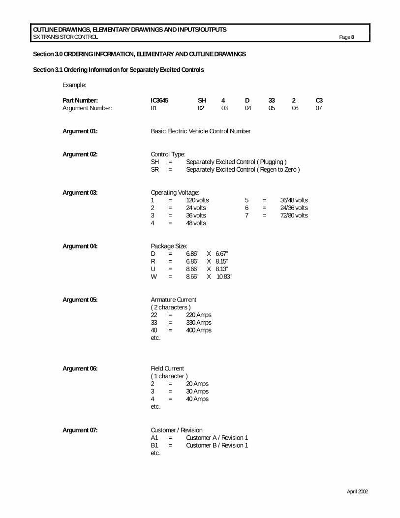
Example: Part Number: IC3645 SH 4 D 33 2 C3 Argument Number: 01 02 03 04 05 06 07 Argument 01: Basic Electric Vehicle Control Number Argument 02: Control Type: SH = Separately Excited Control ( Plugging ) SR = Separately Excited Control ( Regen to Zero ) Argument 03: Operating Voltage: 1 = 120 volts 5 = 36/48 volts 2 = 24 volts 6 = 24/36 volts 3 = 36 volts 7 = 72/80 volts 4 = 48 volts Argument 04: Package Size: D = 6.86” X 6.67” R = 6.86” X 8.15” U = 8.66” X 8.13” W = 8.66” X 10.83” Argument 05: Armature Current ( 2 characters ) 22 = 220 Amps 33 = 330 Amps 40 = 400 Amps etc.
Argument 06: Field Current ( 1 character ) 2 = 20 Amps 3 = 30 Amps 4 = 40 Amps etc. Argument 07: Customer / Revision A1 = Customer A / Revision 1 B1 = Customer B / Revision 1 etc.
OUTLINE DRAWINGS, ELEMENTARY DRAWINGS AND INPUTS/OUTPUTS SX TRANSISTOR CONTROL Page 9
April 2002
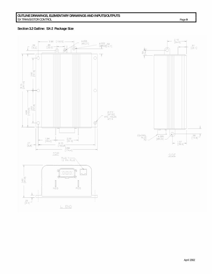
Section 3.2 Outline: SX-2 Package Size
OUTLINE DRAWINGS, ELEMENTARY DRAWINGS AND INPUTS/OUTPUTS SX TRANSISTOR CONTROL Page 10
April 2002
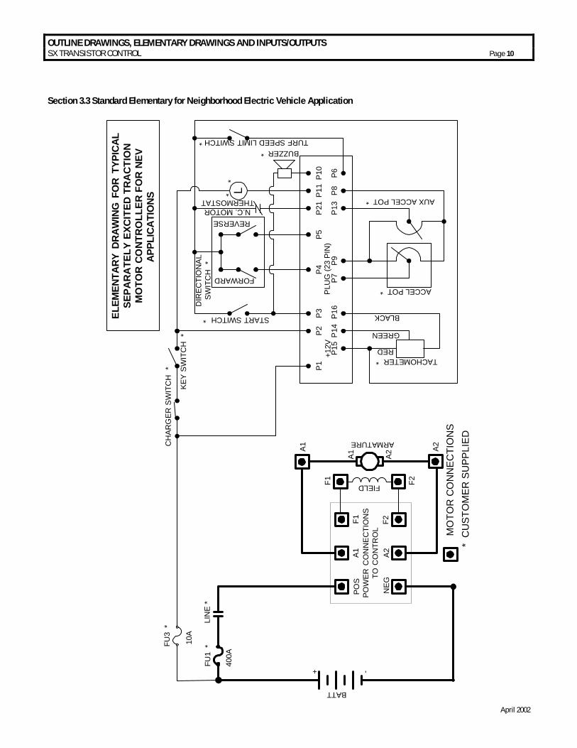
Section 3.3 Standard Elementary for Neighborhood Electric Vehicle Application
POW
ER C
ON
NEC
TIO
NS
TO C
ON
TRO
L
POS
A1F1
NEG
A2F2
FIELD
ARMATURE
FU1
*LI
NE
*
A1 A2
A1 A2
F2F1
BATT
400A
+ -
FU3
*
L
TURF SPEED LIMIT SWITCH *
10A
CH
ARG
ER S
WIT
CH
*
KEY
SWIT
CH
*
START SWITCH *
DIR
ECTI
ON
ALSW
ITC
H *
FORWARD
REVERSEN.C. MOTOR
THERMOSTAT*
BUZZER *
AUX ACCEL POT *
ACCEL POT *
P1P2
P3P4
P5P2
1P1
1P1
0
P15
TACHOMETER *
P14
+12V
P16
P7P9
P13
P8P6
RED
GREEN
BLACKELEM
ENTA
RY D
RAW
ING
FO
R TY
PICA
LSE
PAR
ATE
LY E
XCIT
ED T
RA
CTI
ON
MO
TOR
CO
NTR
OLL
ER F
OR
NEV
APPL
ICAT
IONS
MO
TOR
CO
NN
ECTI
ON
S*
CU
STO
MER
SU
PPLI
ED
PLU
G (2
3 PI
N)
*
OUTLINE DRAWINGS, ELEMENTARY DRAWINGS AND INPUTS/OUTPUTS SX TRANSISTOR CONTROL Page 11
April 2002
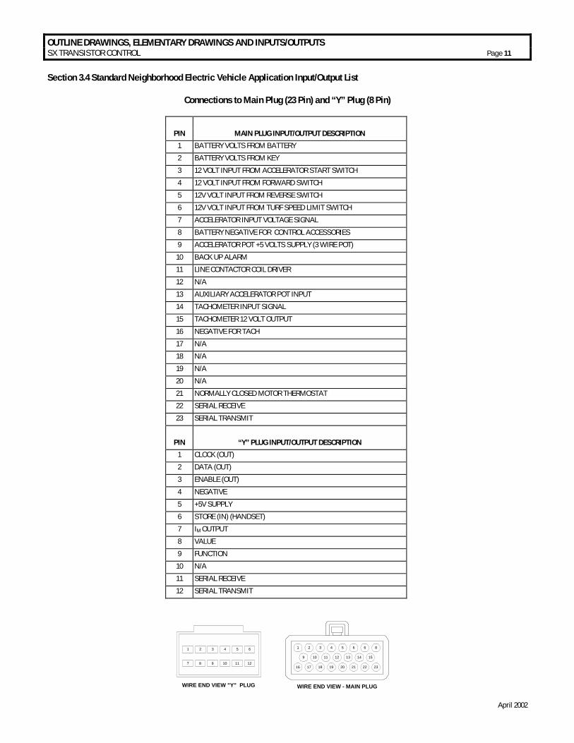
Section 3.4 Standard Neighborhood Electric Vehicle Application Input/Output List
Connections to Main Plug (23 Pin) and “Y” Plug (8 Pin)
PIN MAIN PLUG INPUT/OUTPUT DESCRIPTION
1 BATTERY VOLTS FROM BATTERY
2 BATTERY VOLTS FROM KEY
3 12 VOLT INPUT FROM ACCELERATOR START SWITCH
4 12 VOLT INPUT FROM FORWARD SWITCH
5 12V VOLT INPUT FROM REVERSE SWITCH
6 12V VOLT INPUT FROM TURF SPEED LIMIT SWITCH
7 ACCELERATOR INPUT VOLTAGE SIGNAL
8 BATTERY NEGATIVE FOR CONTROL ACCESSORIES
9 ACCELERATOR POT +5 VOLTS SUPPLY (3 WIRE POT)
10 BACK UP ALARM
11 LINE CONTACTOR COIL DRIVER
12 N/A
13 AUXILIARY ACCELERATOR POT INPUT
14 TACHOMETER INPUT SIGNAL
15 TACHOMETER 12 VOLT OUTPUT
16 NEGATIVE FOR TACH
17 N/A
18 N/A
19 N/A
20 N/A
21 NORMALLY CLOSED MOTOR THERMOSTAT
22 SERIAL RECEIVE
23 SERIAL TRANSMIT
PIN “Y” PLUG INPUT/OUTPUT DESCRIPTION
1 CLOCK (OUT)
2 DATA (OUT)
3 ENABLE (OUT)
4 NEGATIVE
5 +5V SUPPLY
6 STORE (IN) (HANDSET)
7 IM OUTPUT
8 VALUE
9 FUNCTION
10 N/A
11 SERIAL RECEIVE
12 SERIAL TRANSMIT
1 2 3 4 5 6 1 2 3 4 5 6 6 8
9 10 11 12 13 14 15
16 17 18 19 20 21 22 23
WIRE END VIEW - MAIN PLUGWIRE END VIEW "Y" PLUG
7 8 9 10 11 12
DIAGNOSTIC STATUS CODES SX TRANSISTOR CONTROL Page 12
April 2002
Section 4.0 TROUBLESHOOTING AND DIAGNOSTIC STATUS CODES Section 4.1 General Maintenance Instructions The transistor control, like all electrical apparatus, does have some thermal losses. The semiconductor junctions have finite temperature limits, above which these devices may be damaged. For these reasons, normal maintenance should guard against any action which will expose the components to excessive heat and/or those conditions which will reduce the heat dissipating ability of the control, such as restricting air flow. The following Do’s and Don’t’s should be observed: Any controls that will be applied in ambient temperatures over 100° F (40° C) should be brought to the attention of the vehicle manufacturer. All external components having inductive coils must be filtered. Refer to vehicle manufacturer for specifications. The wiring should not be directly steam cleaned. In dusty areas, blow low-pressure air over the control to remove dust. In oily or greasy areas, a mild solution of detergent or denatured alcohol can be used to wash the control, and then low-pressure air should be used to completely dry the control. For the control to be most effective, it must be mounted against the frame of the vehicle. The metal vehicle frame, acting as an additional heat sink, will give improved vehicle performance by keeping the control package cooler. Apply a thin layer of heat-transfer grease (such as Dow Corning 340) between the control heat sink and the vehicle frame. Control wire plugs and other exposed transistor control parts should be kept free of dirt and paint that might change the effective resistance between points. CAUTION: The vehicle should not be plugged when the vehicle is jacked up and the drive wheels are in a free wheeling position. The higher motor speeds can create excessive voltages that can be harmful to the control. Do not hipot (or megger) the control. Refer to control manufacturer before hipotting. Use a lead-acid battery with the voltage and ampere hour rating specified for the vehicle. Follow normal battery maintenance procedures, recharging before 80 percent discharged with periodic equalizing charges. Visual inspection of GE contactors contained in the traction and pump systems is recommended to occur during every
160 hours of vehicle operation. Inspection is recommended to verify that the contactors are not binding and that the tips are intact and free of contaminants. GE does not recommend that any type of welding be performed on the vehicle after the installation of the control(s) in the vehicle. GE will not honor control failures during the warranty period when such failures are attributed to welding while the control is installed in the vehicle. Section 4.2 Cable Routing and Separation Electrical noise from cabling of various voltage levels can interfere with a microprocessor-based control system. To reduce this interference, GE recommends specific cable separation and routing practices, consistent with industry standards. Section 4.2.1 Application Responsibility The customer and customer’s representative are responsible for the mechanical and environmental locations of cables. They are also responsible for applying the level rules and cabling practices defined in this section. To help ensure a lower cost, noise-free installation, GE recommends early planning of cable routing that complies with these level separation rules.
On new installations, sufficient space should be allowed to efficiently arrange mechanical and electrical equipment.
On vehicle retrofits, level rules should be considered during the planning stages to help ensure correct application and a more trouble-free installation.
Section 4.2.2. Signal/Power Level Definitions
The signal/power carrying cables are categorized into four defining levels: low, high, medium power, and high power. Within those levels, signals can be further divided into classes.
Sections 4.2.2.a through 4.2.2.d define these levels and classes, with specific examples of each. Section 4.2.3 contains recommendations for separating the levels. 4.2.2.a Low-Level Signals (Level L) Low-level signals are designated as level L. These consist of: • = Analog signals 0 through ±15 V • = Digital signals whose logic levels are less than 15 V DC • = 4 – 20 mA current loops • = DC busses less than 15 V and 250 mA
The following are specific examples of level L signals used in drive equipment cabling:
DIAGNOSTIC STATUS CODES SX TRANSISTOR CONTROL Page 13
April 2002
• = Control common tie • = DC buses feeding sensitive analog or digital hardware • = All wiring connected to components associated with
sensitive analog hardware with less than 5V signals (for example, potentiometers and tachometers)
• = Digital tachometers and resolvers • = Dash display cabling • = RS-232 cabling Note: Signal inputs to analog and digital blocks should be run as shielded twisted-pair (for example, inputs from tachometers, potentiometers, and dash displays). 4.2.2.b High-Level Signals (Level H) High-level signals are designated as level H. These signals consist of: • = Analog and digital signals greater than 15 V DC and
less than 250 mA For example, switch inputs connected to battery volts are examples of level H signals used in drive equipment cabling. 4.2.2.c Medium-Power Signals (Level MP) Medium power signals are designated as level MP. These signals consist of: • = DC switching signals greater than 15 V • = Signals with currents greater than 250 mA and less than
10A The following are specific examples of level MP signals used in drive equipment cabling: • = DC busses less than 10 A • = Contactor coils less than 10 A • = Machine fields less than 10 A 4.2.2.d. High Power Signals (Level HP) Power wiring is designated as level HP. This consists of DC buses and motor wiring with currents greater than 10 A. The following are specific examples of level HP signals used in drive equipment cabling: • = Motor armature loops • = DC outputs 10 A and above • = Motor field loops 10 A and above
4.2.3. Cable Spacing Guidelines
Recommended spacing (or clearance) between cables (or wires) is dependent on the level of the wiring inside them. For correct level separation when installing cable, the
customer must apply the general guidelines (section 4.2.3.a), outlined below. 4.2.3.a General Cable Spacing The following general practices should be used for all levels of cabling: • = All cables and wires of like signal levels and power
levels must be grouped together. • = In general, different levels must run in separate wire
bundles, as defined in the different classes, identified above. Intermixing cannot be allowed, unless noted by exception.
• = Interconnecting wire runs should carry a level designation.
• = If wires are the same level and same type signal, group those wires from one location to any other location together in multiconductor cables or bind them together with twine or zip-ties.
• = When unlike signals must cross, cross them in 90° angles at a maximum spacing. Where it is not possible to maintain spacing, place a grounded steel barrier between unlike levels at the crossover point.
4.2.4 Cabling for Vehicle Retrofits Reducing electrical noise on vehicle retrofits requires careful planning. Lower and higher levels should never encircle each other or run parallel for long distances. It is practical to use existing wire runs or trays as long as the level spacing (see section 4.2.2) can be maintained for the full length of the run.
Existing cables are generally of high voltage potential and noise producing. Therefore, route levels L and H in a path separate from existing cables, whenever possible.
For level L wiring, use barriers in existing wire runs to minimize noise potential.
Do not loop level L signal wires around level H, level MP, or HP wires. 4.2.5 RF Interference To prevent radio frequency (RF) interference, care should be taken in routing power cables in the vicinity of radio-controlled devices. Section 4.2.6 Suppression Unless specifically noted otherwise, suppression (for example, a snubber) is required on all inductive devices controlled by an output. This suppression minimizes noise and prevents damage caused by electrical surges.
DIAGNOSTIC STATUS CODES SX TRANSISTOR CONTROL Page 14
April 2002
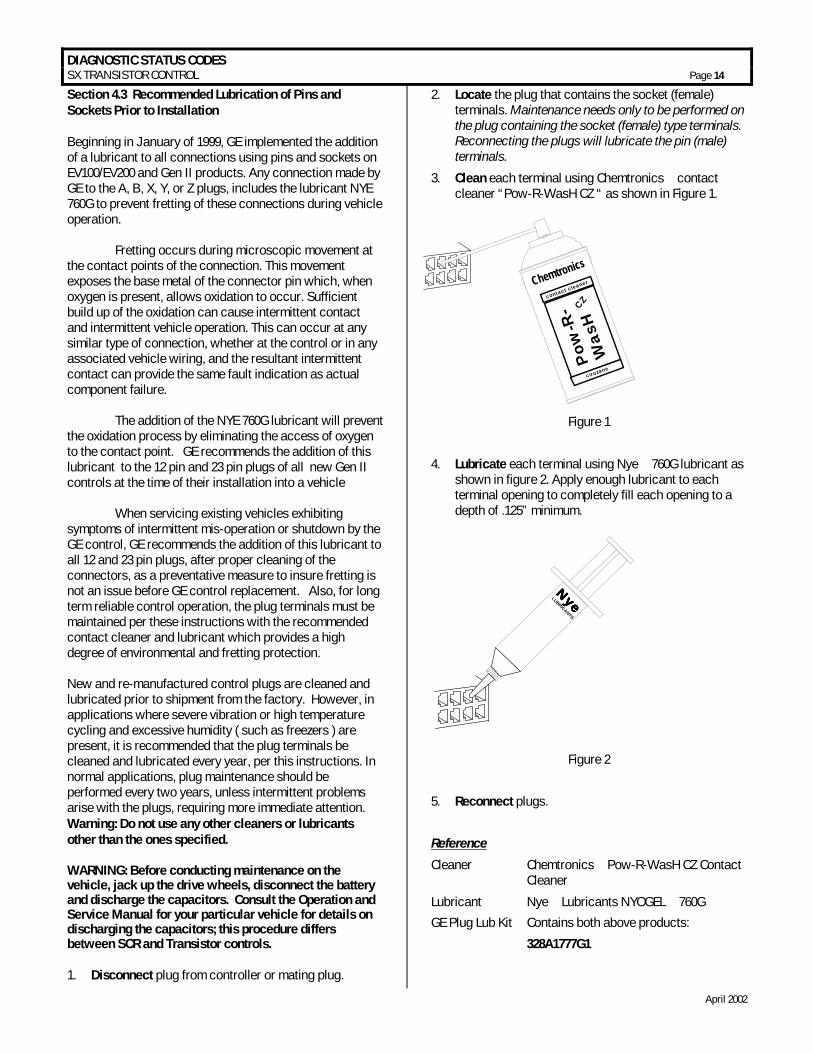
Section 4.3 Recommended Lubrication of Pins and Sockets Prior to Installation Beginning in January of 1999, GE implemented the addition of a lubricant to all connections using pins and sockets on EV100/EV200 and Gen II products. Any connection made by GE to the A, B, X, Y, or Z plugs, includes the lubricant NYE 760G to prevent fretting of these connections during vehicle operation. Fretting occurs during microscopic movement at the contact points of the connection. This movement exposes the base metal of the connector pin which, when oxygen is present, allows oxidation to occur. Sufficient build up of the oxidation can cause intermittent contact and intermittent vehicle operation. This can occur at any similar type of connection, whether at the control or in any associated vehicle wiring, and the resultant intermittent contact can provide the same fault indication as actual component failure. The addition of the NYE 760G lubricant will prevent the oxidation process by eliminating the access of oxygen to the contact point. GE recommends the addition of this lubricant to the 12 pin and 23 pin plugs of all new Gen II controls at the time of their installation into a vehicle When servicing existing vehicles exhibiting symptoms of intermittent mis-operation or shutdown by the GE control, GE recommends the addition of this lubricant to all 12 and 23 pin plugs, after proper cleaning of the connectors, as a preventative measure to insure fretting is not an issue before GE control replacement. Also, for long term reliable control operation, the plug terminals must be maintained per these instructions with the recommended contact cleaner and lubricant which provides a high degree of environmental and fretting protection. New and re-manufactured control plugs are cleaned and lubricated prior to shipment from the factory. However, in applications where severe vibration or high temperature cycling and excessive humidity ( such as freezers ) are present, it is recommended that the plug terminals be cleaned and lubricated every year, per this instructions. In normal applications, plug maintenance should be performed every two years, unless intermittent problems arise with the plugs, requiring more immediate attention. Warning: Do not use any other cleaners or lubricants other than the ones specified. WARNING: Before conducting maintenance on the vehicle, jack up the drive wheels, disconnect the battery and discharge the capacitors. Consult the Operation and Service Manual for your particular vehicle for details on discharging the capacitors; this procedure differs between SCR and Transistor controls. 1. Disconnect plug from controller or mating plug.
2. Locate the plug that contains the socket (female) terminals. Maintenance needs only to be performed on the plug containing the socket (female) type terminals. Reconnecting the plugs will lubricate the pin (male) terminals.
3. Clean each terminal using Chemtronics contact cleaner “Pow-R-WasH CZ “ as shown in Figure 1.
Figure 1
4. Lubricate each terminal using Nye 760G lubricant as shown in figure 2. Apply enough lubricant to each terminal opening to completely fill each opening to a depth of .125” minimum.
Figure 2
5. Reconnect plugs.
Reference
Cleaner Chemtronics Pow-R-WasH CZ Contact Cleaner
Lubricant Nye Lubricants NYOGEL 760G
GE Plug Lub Kit Contains both above products:
328A1777G1
Chemtronics
Pow
-R-
Was
HCZcontact cleaner
cirozane
NyeNyeNyeNyeLUBRICANTS
DIAGNOSTIC STATUS CODES SX TRANSISTOR CONTROL Page 15
April 2002
Section 4.4 General Troubleshooting Instructions Trouble-shooting the ZX family of controls should be quick and easy when following the instructions outlined in the following status code instruction sheets. If mis-operation of the vehicle occurs, a status code will be displayed on the Dash Display (for vehicles equipped with a Dash Display) or made available by plugging a Handset into the plug "Y" location, and then reading the status code. With the status code number, follow the procedures outlined in the status code instruction sheets to determine the problem. Important Note: Due to the interaction of the logic card with all vehicle functions, almost any status code or control fault could be caused by the logic card. After all other status code procedures have been followed and no problem is found, the controller should then be replaced as the last option to correct the problem. The same device designations have been maintained on different controls but the wire numbers may vary. Refer to the elementary and wiring diagrams for your specific control. The wire numbers shown on the elementary diagram will have identical numbers on the corresponding wiring diagrams for a specific vehicle, but these numbers may be different from the numbers referenced in this publication. WARNING: Before trouble-shooting, jack up the drive wheels, disconnect the battery and discharge the capacitors. Reconnect the battery as needed for specific checks. Capacitors should be discharged by connecting a 200 ohm 2 watt resistor between the positive and negative terminals on the control panel. Check resistance on R x 1000 scale from frame to power and control terminals. A resistance of less than 20,000 ohms can cause misleading symptoms. Resistance less than 1000 ohms should be corrected first. Before proceeding, visually check for loose wiring, mis-aligned linkage to the accelerator switch, signs of overheating of components, etc. Tools and test equipment required are: clip leads, volt-ohm meter (20,000 ohms per volt) and basic hand tools.
DIAGNOSTIC STATUS CODES SX TRANSISTOR CONTROL Page 16
April 2002
Section 4.5 Traction Control Codes
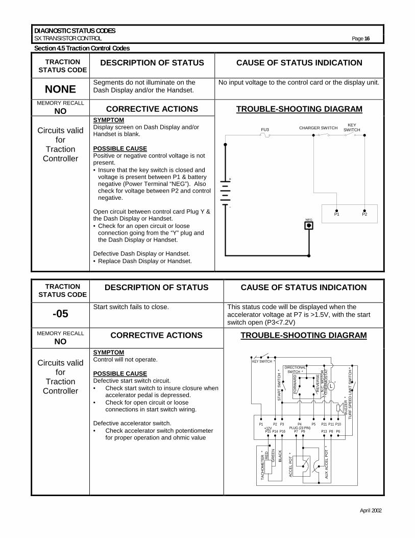
TRACTION STATUS CODE
DESCRIPTION OF STATUS CAUSE OF STATUS INDICATION
NONE Segments do not illuminate on the Dash Display and/or the Handset.
No input voltage to the control card or the display unit.
MEMORY RECALL NO CORRECTIVE ACTIONS TROUBLE-SHOOTING DIAGRAM
Circuits valid
for Traction
Controller
SYMPTOM Display screen on Dash Display and/or Handset is blank. POSSIBLE CAUSE Positive or negative control voltage is not present. • = Insure that the key switch is closed and
voltage is present between P1 & battery negative (Power Terminal “NEG”). Also check for voltage between P2 and control negative.
Open circuit between control card Plug Y & the Dash Display or Handset. • =Check for an open circuit or loose
connection going from the “Y” plug and the Dash Display or Handset.
Defective Dash Display or Handset. • =Replace Dash Display or Handset.
FU3KEY
SWITCH
P1 P2NEG
+
-
CHARGER SWITCH
TRACTION STATUS CODE
DESCRIPTION OF STATUS CAUSE OF STATUS INDICATION
-05 Start switch fails to close. This status code will be displayed when the
accelerator voltage at P7 is >1.5V, with the start switch open (P3<7.2V)
MEMORY RECALL NO CORRECTIVE ACTIONS TROUBLE-SHOOTING DIAGRAM
Circuits valid
for Traction
Controller
SYMPTOM Control will not operate. POSSIBLE CAUSE Defective start switch circuit. • = Check start switch to insure closure when
accelerator pedal is depressed. • = Check for open circuit or loose
connections in start switch wiring. Defective accelerator switch. • = Check accelerator switch potentiometer
for proper operation and ohmic value
L
TUR
F S
PEED
LIM
IT S
WIT
CH
*
KEY SWITCH *
STA
RT
SWIT
CH
*
DIRECTIONALSWITCH *
FOR
WA
RD
REV
ER
SEN
.C. M
OTO
RTH
ERM
OST
AT*
BU
ZZER
*
AUX
ACC
EL P
OT
*
ACC
EL P
OT
*
P1 P2 P3 P4 P5 P21 P11 P10
P15
TAC
HO
MET
ER
*
P14+12V
P16 P7 P9 P13 P8 P6
RED
GR
EEN
BLAC
K
PLUG (23 PIN)
*
DIAGNOSTIC STATUS CODES SX TRANSISTOR CONTROL Page 17
April 2002
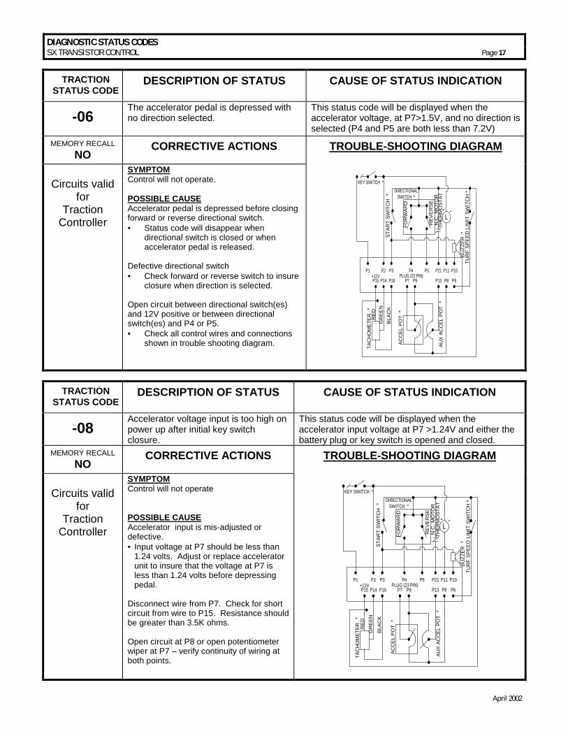
TRACTION STATUS CODE
DESCRIPTION OF STATUS CAUSE OF STATUS INDICATION
-06 The accelerator pedal is depressed with no direction selected.
This status code will be displayed when the accelerator voltage, at P7>1.5V, and no direction is selected (P4 and P5 are both less than 7.2V)
MEMORY RECALL NO CORRECTIVE ACTIONS TROUBLE-SHOOTING DIAGRAM
Circuits valid
for Traction
Controller
SYMPTOM Control will not operate. POSSIBLE CAUSE Accelerator pedal is depressed before closing forward or reverse directional switch. • = Status code will disappear when
directional switch is closed or when accelerator pedal is released.
Defective directional switch • = Check forward or reverse switch to insure
closure when direction is selected. Open circuit between directional switch(es) and 12V positive or between directional switch(es) and P4 or P5. • = Check all control wires and connections
shown in trouble shooting diagram.
L
TUR
F SP
EED
LIM
IT S
WIT
CH
*
KEY SWITCH *
STAR
T SW
ITC
H *
DIRECTIONALSWITCH *
FOR
WAR
D
REV
ER
SEN
.C. M
OTO
RTH
ERM
OST
AT*
BUZZ
ER *
AUX
ACC
EL P
OT
*
ACC
EL P
OT
*
P1 P2 P3 P4 P5 P21 P11 P10
P15
TAC
HO
MET
ER
*
P14+12V
P16 P7 P9 P13 P8 P6
RE
DG
REE
NBL
ACK
PLUG (23 PIN)
*
TRACTION STATUS CODE
DESCRIPTION OF STATUS CAUSE OF STATUS INDICATION
-08 Accelerator voltage input is too high on power up after initial key switch closure.
This status code will be displayed when the accelerator input voltage at P7 >1.24V and either the battery plug or key switch is opened and closed.
MEMORY RECALL NO CORRECTIVE ACTIONS TROUBLE-SHOOTING DIAGRAM
Circuits valid
for Traction
Controller
SYMPTOM Control will not operate POSSIBLE CAUSE Accelerator input is mis-adjusted or defective. • = Input voltage at P7 should be less than
1.24 volts. Adjust or replace accelerator unit to insure that the voltage at P7 is less than 1.24 volts before depressing pedal.
Disconnect wire from P7. Check for short circuit from wire to P15. Resistance should be greater than 3.5K ohms. Open circuit at P8 or open potentiometer wiper at P7 – verify continuity of wiring at both points.
L
TUR
F SP
EED
LIM
IT S
WIT
CH
*
KEY SWITCH *
STAR
T SW
ITC
H *
DIRECTIONALSWITCH *
FOR
WAR
D
REV
ER
SEN
.C. M
OTO
RTH
ERM
OST
AT*
BUZZ
ER *
AUX
ACC
EL P
OT
*
ACC
EL P
OT
*
P1 P2 P3 P4 P5 P21 P11 P10
P15
TAC
HO
MET
ER
*
P14+12V
P16 P7 P9 P13 P8 P6
RE
DG
REE
N
BLAC
K
PLUG (23 PIN)
*
DIAGNOSTIC STATUS CODES SX TRANSISTOR CONTROL Page 18
April 2002
TRACTION STATUS CODE
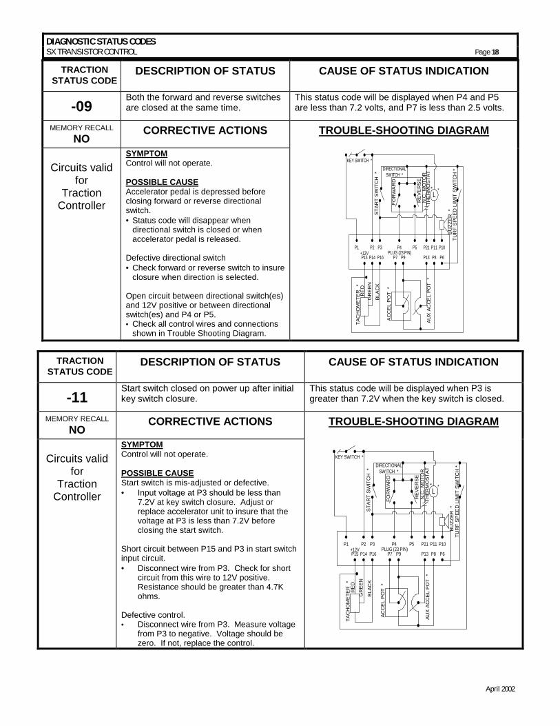
DESCRIPTION OF STATUS CAUSE OF STATUS INDICATION
-09 Both the forward and reverse switches are closed at the same time.
This status code will be displayed when P4 and P5 are less than 7.2 volts, and P7 is less than 2.5 volts.
MEMORY RECALL NO CORRECTIVE ACTIONS TROUBLE-SHOOTING DIAGRAM
Circuits valid
for Traction
Controller
SYMPTOM Control will not operate. POSSIBLE CAUSE Accelerator pedal is depressed before closing forward or reverse directional switch. • =Status code will disappear when
directional switch is closed or when accelerator pedal is released.
Defective directional switch • =Check forward or reverse switch to insure
closure when direction is selected. Open circuit between directional switch(es) and 12V positive or between directional switch(es) and P4 or P5. • =Check all control wires and connections
shown in Trouble Shooting Diagram.
L
TUR
F SP
EED
LIM
IT S
WIT
CH
*
KEY SWITCH *
STAR
T SW
ITC
H *
DIRECTIONALSWITCH *
FOR
WAR
D
REV
ER
SEN
.C. M
OTO
RTH
ERM
OST
AT*
BUZZ
ER *
AUX
ACC
EL P
OT
*
ACC
EL P
OT
*
P1 P2 P3 P4 P5 P21 P11 P10
P15
TAC
HO
MET
ER
*
P14+12V
P16 P7 P9 P13 P8 P6
RE
DG
REE
NBL
ACK
PLUG (23 PIN)
*
TRACTION STATUS CODE
DESCRIPTION OF STATUS CAUSE OF STATUS INDICATION
-11 Start switch closed on power up after initial key switch closure.
This status code will be displayed when P3 is greater than 7.2V when the key switch is closed.
MEMORY RECALL NO CORRECTIVE ACTIONS TROUBLE-SHOOTING DIAGRAM
Circuits valid
for Traction
Controller
SYMPTOM Control will not operate. POSSIBLE CAUSE Start switch is mis-adjusted or defective. • = Input voltage at P3 should be less than
7.2V at key switch closure. Adjust or replace accelerator unit to insure that the voltage at P3 is less than 7.2V before closing the start switch.
Short circuit between P15 and P3 in start switch input circuit. • = Disconnect wire from P3. Check for short
circuit from this wire to 12V positive. Resistance should be greater than 4.7K ohms.
Defective control. • = Disconnect wire from P3. Measure voltage
from P3 to negative. Voltage should be zero. If not, replace the control.
L
TUR
F SP
EED
LIM
IT S
WIT
CH
*KEY SWITCH *
STAR
T SW
ITC
H *
DIRECTIONALSWITCH *
FOR
WAR
D
REV
ER
SEN
.C. M
OTO
RTH
ERM
OST
AT*
BUZZ
ER *
AUX
ACC
EL P
OT
*
ACC
EL P
OT
*
P1 P2 P3 P4 P5 P21 P11 P10
P15
TAC
HO
MET
ER
*
P14+12V
P16 P7 P9 P13 P8 P6
RE
DG
REE
N
BLAC
K
PLUG (23 PIN)
*
DIAGNOSTIC STATUS CODES SX TRANSISTOR CONTROL Page 19
April 2002
TRACTION STATUS CODE
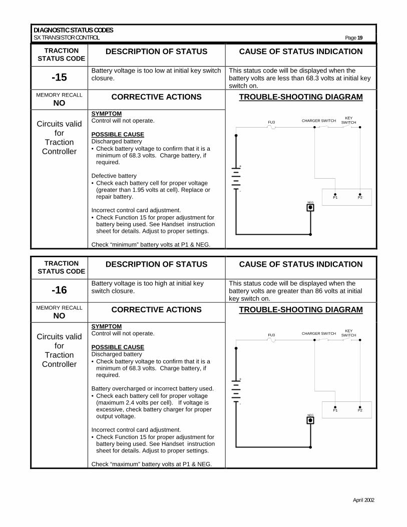
DESCRIPTION OF STATUS CAUSE OF STATUS INDICATION
-15 Battery voltage is too low at initial key switch closure.
This status code will be displayed when the battery volts are less than 68.3 volts at initial key switch on.
MEMORY RECALL NO CORRECTIVE ACTIONS TROUBLE-SHOOTING DIAGRAM
Circuits valid
for Traction
Controller
SYMPTOM Control will not operate. POSSIBLE CAUSE Discharged battery • =Check battery voltage to confirm that it is a
minimum of 68.3 volts. Charge battery, if required.
Defective battery • =Check each battery cell for proper voltage
(greater than 1.95 volts at cell). Replace or repair battery.
Incorrect control card adjustment. • =Check Function 15 for proper adjustment for
battery being used. See Handset instruction sheet for details. Adjust to proper settings.
Check “minimum” battery volts at P1 & NEG.
FU3KEY
SWITCH
P1 P2NEG
+
-
CHARGER SWITCH
TRACTION STATUS CODE
DESCRIPTION OF STATUS CAUSE OF STATUS INDICATION
-16 Battery voltage is too high at initial key switch closure.
This status code will be displayed when the battery volts are greater than 86 volts at initial key switch on.
MEMORY RECALL NO CORRECTIVE ACTIONS TROUBLE-SHOOTING DIAGRAM
Circuits valid
for Traction
Controller
SYMPTOM Control will not operate. POSSIBLE CAUSE Discharged battery • =Check battery voltage to confirm that it is a
minimum of 68.3 volts. Charge battery, if required.
Battery overcharged or incorrect battery used. • =Check each battery cell for proper voltage
(maximum 2.4 volts per cell). If voltage is excessive, check battery charger for proper output voltage.
Incorrect control card adjustment. • =Check Function 15 for proper adjustment for
battery being used. See Handset instruction sheet for details. Adjust to proper settings.
Check “maximum” battery volts at P1 & NEG.
FU3KEY
SWITCH
P1 P2NEG
+
-
CHARGER SWITCH
DIAGNOSTIC STATUS CODES SX TRANSISTOR CONTROL Page 20
April 2002
TRACTION STATUS CODE
DESCRIPTION OF STATUS CAUSE OF STATUS INDICATION
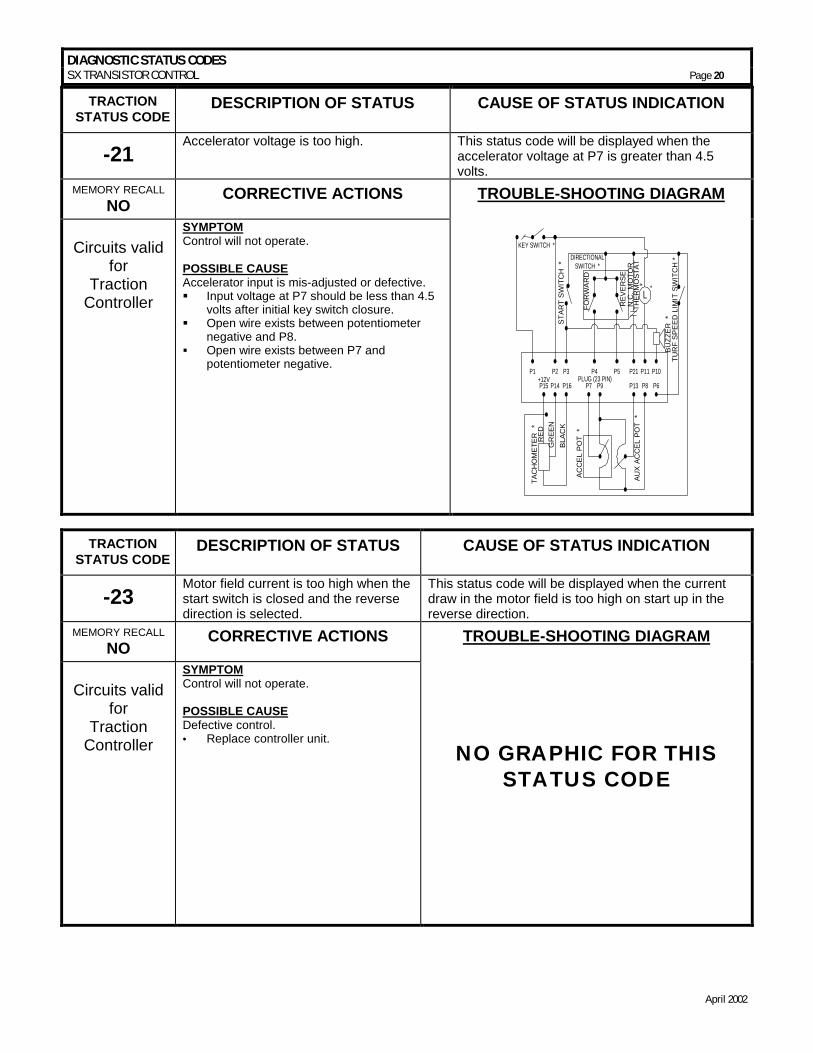
-21 Accelerator voltage is too high. This status code will be displayed when the
accelerator voltage at P7 is greater than 4.5 volts.
MEMORY RECALL NO CORRECTIVE ACTIONS TROUBLE-SHOOTING DIAGRAM
Circuits valid
for Traction
Controller
SYMPTOM Control will not operate. POSSIBLE CAUSE Accelerator input is mis-adjusted or defective. �� Input voltage at P7 should be less than 4.5
volts after initial key switch closure. �� Open wire exists between potentiometer
negative and P8. �� Open wire exists between P7 and
potentiometer negative.
L
TUR
F SP
EED
LIM
IT S
WIT
CH
*
KEY SWITCH *
STAR
T SW
ITC
H *
DIRECTIONALSWITCH *
FOR
WAR
D
REV
ER
SEN
.C. M
OTO
RTH
ERM
OST
AT*
BUZZ
ER *
AUX
ACC
EL P
OT
*
ACC
EL P
OT
*
P1 P2 P3 P4 P5 P21 P11 P10
P15
TAC
HO
MET
ER
*
P14+12V
P16 P7 P9 P13 P8 P6
RE
DG
REE
NBL
ACK
PLUG (23 PIN)
*
TRACTION STATUS CODE
DESCRIPTION OF STATUS CAUSE OF STATUS INDICATION
-23 Motor field current is too high when the start switch is closed and the reverse direction is selected.
This status code will be displayed when the current draw in the motor field is too high on start up in the reverse direction.
MEMORY RECALL NO CORRECTIVE ACTIONS TROUBLE-SHOOTING DIAGRAM
Circuits valid
for Traction
Controller
SYMPTOM Control will not operate. POSSIBLE CAUSE Defective control. • = Replace controller unit.
NO GRAPHIC FOR THIS STATUS CODE
DIAGNOSTIC STATUS CODES SX TRANSISTOR CONTROL Page 21
April 2002
TRACTION STATUS CODE
DESCRIPTION OF STATUS CAUSE OF STATUS INDICATION
-24 Motor field current is too high on when the start switch is closed and the forward direction is selected.
This status code will be displayed when the current draw in the motor field is too high on start up in the forward direction.
MEMORY RECALL NO CORRECTIVE ACTIONS TROUBLE-SHOOTING DIAGRAM
Circuits valid
for Traction
Controller
SYMPTOM Control will not operate. POSSIBLE CAUSE Defective control. • = Replace controller unit.
NO GRAPHIC FOR THIS STATUS CODE
TRACTION
STATUS CODE DESCRIPTION OF STATUS CAUSE OF STATUS INDICATION
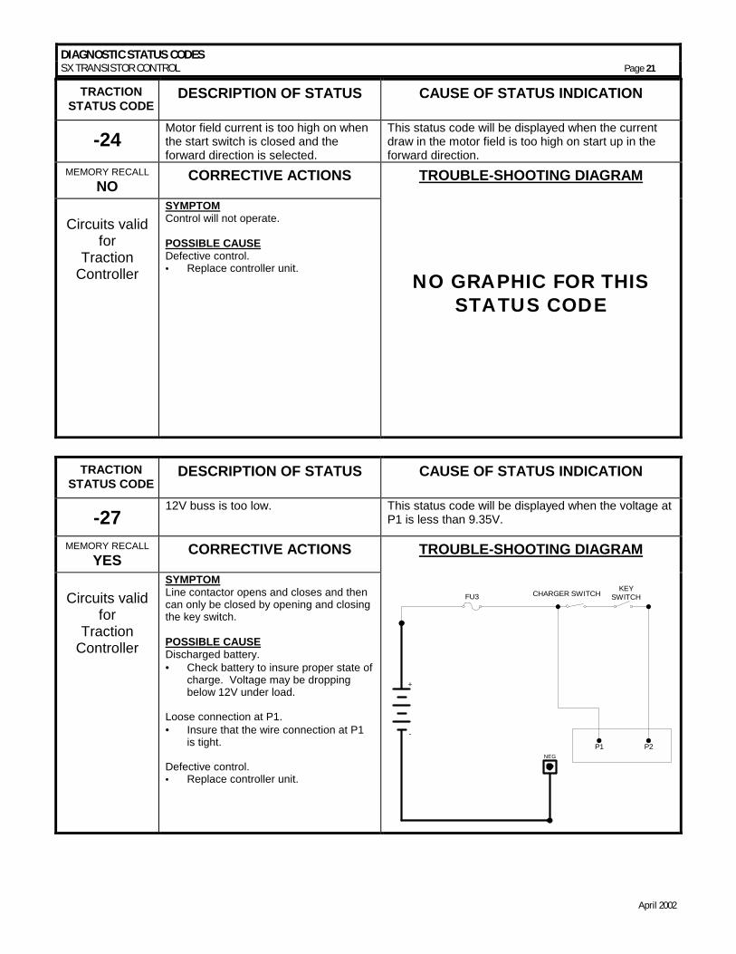
-27 12V buss is too low. This status code will be displayed when the voltage at
P1 is less than 9.35V.
MEMORY RECALL YES CORRECTIVE ACTIONS TROUBLE-SHOOTING DIAGRAM
Circuits valid
for Traction
Controller
SYMPTOM Line contactor opens and closes and then can only be closed by opening and closing the key switch. POSSIBLE CAUSE Discharged battery. • = Check battery to insure proper state of
charge. Voltage may be dropping below 12V under load.
Loose connection at P1. • = Insure that the wire connection at P1
is tight. Defective control. • = Replace controller unit.
FU3KEY
SWITCH
P1 P2NEG
+
-
CHARGER SWITCH
DIAGNOSTIC STATUS CODES SX TRANSISTOR CONTROL Page 22
April 2002
TRACTION STATUS CODE
DESCRIPTION OF STATUS CAUSE OF STATUS INDICATION
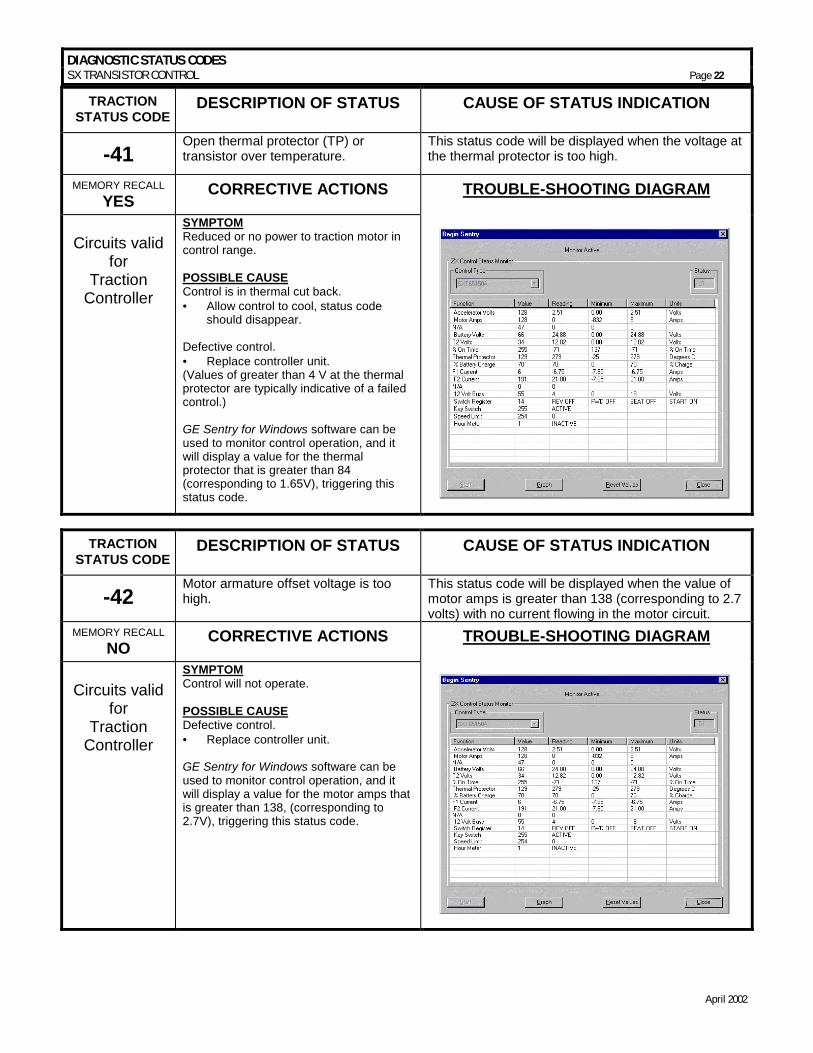
-41 Open thermal protector (TP) or transistor over temperature.
This status code will be displayed when the voltage at the thermal protector is too high.
MEMORY RECALL YES CORRECTIVE ACTIONS TROUBLE-SHOOTING DIAGRAM
Circuits valid
for Traction
Controller
SYMPTOM Reduced or no power to traction motor in control range. POSSIBLE CAUSE Control is in thermal cut back. • = Allow control to cool, status code
should disappear. Defective control. • = Replace controller unit. (Values of greater than 4 V at the thermal protector are typically indicative of a failed control.) GE Sentry for Windows software can be used to monitor control operation, and it will display a value for the thermal protector that is greater than 84 (corresponding to 1.65V), triggering this status code.
TRACTION STATUS CODE
DESCRIPTION OF STATUS CAUSE OF STATUS INDICATION
-42 Motor armature offset voltage is too high.
This status code will be displayed when the value of motor amps is greater than 138 (corresponding to 2.7 volts) with no current flowing in the motor circuit.
MEMORY RECALL NO CORRECTIVE ACTIONS TROUBLE-SHOOTING DIAGRAM
Circuits valid
for Traction
Controller
SYMPTOM Control will not operate. POSSIBLE CAUSE Defective control. • = Replace controller unit. GE Sentry for Windows software can be used to monitor control operation, and it will display a value for the motor amps that is greater than 138, (corresponding to 2.7V), triggering this status code.
DIAGNOSTIC STATUS CODES SX TRANSISTOR CONTROL Page 23
April 2002
TRACTION STATUS CODE
DESCRIPTION OF STATUS CAUSE OF STATUS INDICATION
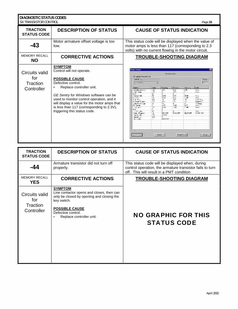
-43 Motor armature offset voltage is too low.
This status code will be displayed when the value of motor amps is less than 117 (corresponding to 2.3 volts) with no current flowing in the motor circuit.
MEMORY RECALL NO CORRECTIVE ACTIONS TROUBLE-SHOOTING DIAGRAM
Circuits valid
for Traction
Controller
SYMPTOM Control will not operate. POSSIBLE CAUSE Defective control. • = Replace controller unit. GE Sentry for Windows software can be used to monitor control operation, and it will display a value for the motor amps that is less than 117 (corresponding to 2.3V), triggering this status code.
TRACTION STATUS CODE
DESCRIPTION OF STATUS CAUSE OF STATUS INDICATION
-44 Armature transistor did not turn off properly.
This status code will be displayed when, during control operation, the armature transistor fails to turn off. This will result in a PMT condition
MEMORY RECALL YES CORRECTIVE ACTIONS TROUBLE-SHOOTING DIAGRAM
Circuits valid
for Traction
Controller
SYMPTOM Line contactor opens and closes, then can only be closed by opening and closing the key switch. POSSIBLE CAUSE Defective control. • = Replace controller unit.
NO GRAPHIC FOR THIS STATUS CODE
DIAGNOSTIC STATUS CODES SX TRANSISTOR CONTROL Page 24
April 2002
TRACTION STATUS CODE
DESCRIPTION OF STATUS CAUSE OF STATUS INDICATION
-45 Armature transistor did not turn on properly.
This status code will be displayed when, during control operation, the armature transistor fails to turn on properly. This will result in a PMT condition
MEMORY RECALL YES CORRECTIVE ACTIONS TROUBLE-SHOOTING DIAGRAM
Circuits valid
for Traction
Controller
SYMPTOM Line contactor opens and closes, then can only be closed by opening and closing the key switch. POSSIBLE CAUSE Defective control. • = Replace controller unit.
NO GRAPHIC FOR THIS STATUS CODE
TRACTION
STATUS CODE DESCRIPTION OF STATUS CAUSE OF STATUS INDICATION
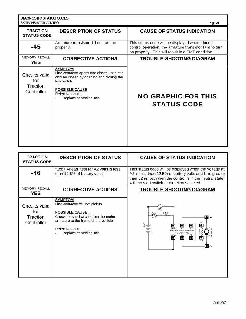
-46 “Look Ahead” test for A2 volts is less than 12.5% of battery volts.
This status code will be displayed when the voltage at A2 is less than 12.5% of battery volts and Im is greater than 52 amps, when the control is in the neutral state, with no start switch or direction selected.
MEMORY RECALL YES CORRECTIVE ACTIONS TROUBLE-SHOOTING DIAGRAM
Circuits valid
for Traction
Controller
SYMPTOM Line contactor will not pickup. POSSIBLE CAUSE Check for short circuit from the motor armature to the frame of the vehicle. Defective control. • = Replace controller unit.
POWER CONNECTIONSTO CONTROL
POS A1 F1
NEG A2 F2
FIEL
D
ARM
ATU
RE
A1
A2
A1
A2
F2
F1
BATT +
-
FU1 * LINE *
400A
FU3 *
10A
DIAGNOSTIC STATUS CODES SX TRANSISTOR CONTROL Page 25
April 2002
TRACTION STATUS CODE
DESCRIPTION OF STATUS CAUSE OF STATUS INDICATION
-49 Motor field current is too low during the run mode.
This status code will be displayed when the current draw in the motor field is less than 1.3 amps and armature current is greater than 100 amps for more than 1.27 seconds during the run mode.
MEMORY RECALL YES CORRECTIVE ACTIONS TROUBLE-SHOOTING DIAGRAM
Circuits valid
for Traction
Controller
SYMPTOM Control will not operate. POSSIBLE CAUSE Defective control. • = Replace controller unit.
NO GRAPHIC FOR THIS STATUS CODE
TRACTION STATUS CODE
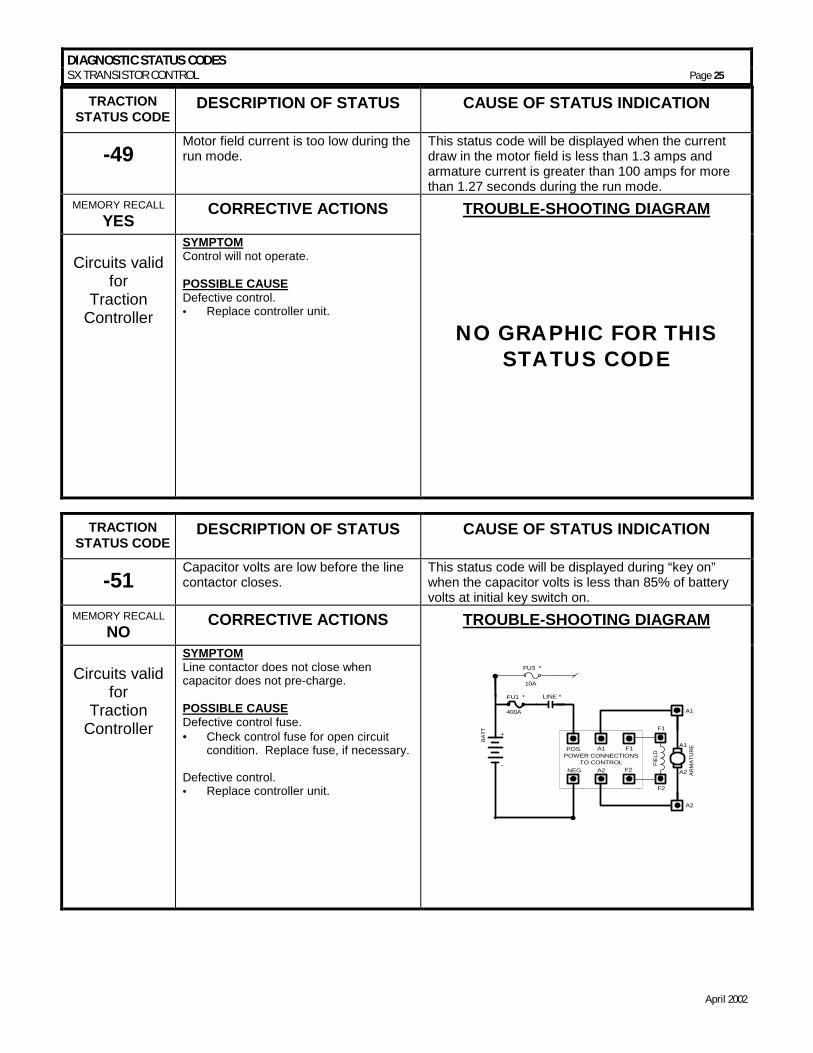
DESCRIPTION OF STATUS CAUSE OF STATUS INDICATION
-51 Capacitor volts are low before the line contactor closes.
This status code will be displayed during “key on” when the capacitor volts is less than 85% of battery volts at initial key switch on.
MEMORY RECALL NO CORRECTIVE ACTIONS TROUBLE-SHOOTING DIAGRAM
Circuits valid
for Traction
Controller
SYMPTOM Line contactor does not close when capacitor does not pre-charge. POSSIBLE CAUSE Defective control fuse. • = Check control fuse for open circuit
condition. Replace fuse, if necessary. Defective control. • = Replace controller unit.
POWER CONNECTIONSTO CONTROL
POS A1 F1
NEG A2 F2
FIEL
D
ARM
ATU
RE
A1
A2
A1
A2
F2
F1
BATT +
-
FU1 * LINE *
400A
FU3 *
10A
DIAGNOSTIC STATUS CODES SX TRANSISTOR CONTROL Page 26
April 2002
TRACTION STATUS CODE
DESCRIPTION OF STATUS CAUSE OF STATUS INDICATION
-57 Controller “motor current sensor” input is too low during running.
This status code will be displayed when the voltage input from the current sensor is too low (less than 1.43V, -350 amps) during running.
MEMORY RECALL YES CORRECTIVE ACTIONS TROUBLE-SHOOTING DIAGRAM
Circuits valid
for Traction
Controller
SYMPTOM Control will not operate. POSSIBLE CAUSE Defective control. • = Replace controller unit. Line contactor tips bounce or are not fully picked up.
NO GRAPHIC FOR THIS STATUS CODE
TRACTION
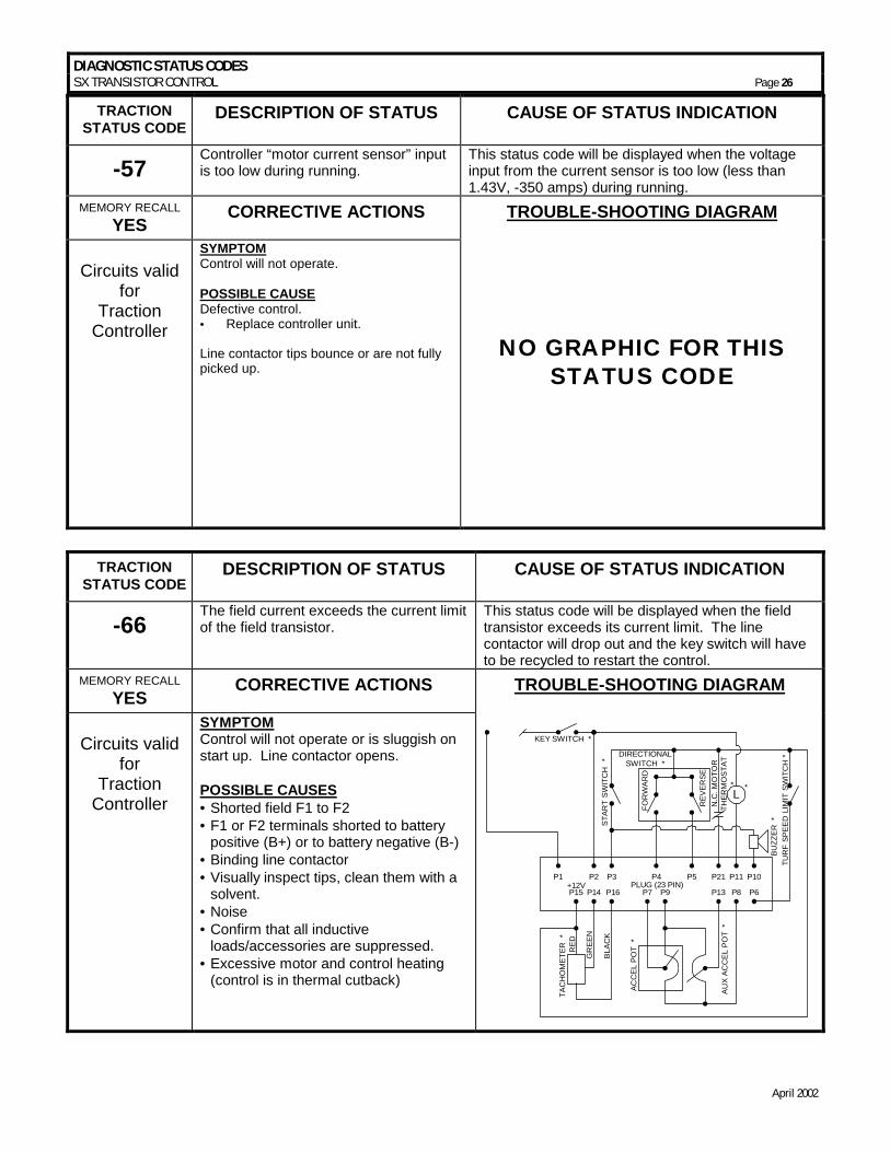
STATUS CODE DESCRIPTION OF STATUS CAUSE OF STATUS INDICATION
-66 The field current exceeds the current limit of the field transistor.
This status code will be displayed when the field transistor exceeds its current limit. The line contactor will drop out and the key switch will have to be recycled to restart the control.
MEMORY RECALL YES CORRECTIVE ACTIONS TROUBLE-SHOOTING DIAGRAM
Circuits valid
for Traction
Controller
SYMPTOM Control will not operate or is sluggish on start up. Line contactor opens. POSSIBLE CAUSES • =Shorted field F1 to F2 • =F1 or F2 terminals shorted to battery
positive (B+) or to battery negative (B-) • =Binding line contactor • =Visually inspect tips, clean them with a
solvent. • =Noise • =Confirm that all inductive
loads/accessories are suppressed. • =Excessive motor and control heating
(control is in thermal cutback)
LTU
RF
SPEE
D L
IMIT
SW
ITC
H *
KEY SWITCH *
STAR
T SW
ITC
H *
DIRECTIONALSWITCH *
FOR
WAR
D
REV
ERSE
N.C
. MO
TOR
THER
MO
STAT
*
BUZZ
ER *
AUX
ACC
EL P
OT
*
ACC
EL P
OT
*
P1 P2 P3 P4 P5 P21 P11 P10
P15
TAC
HO
MET
ER *
P14+12V
P16 P7 P9 P13 P8 P6
RED
GR
EEN
BLAC
K
PLUG (23 PIN)
*
DIAGNOSTIC STATUS CODES SX TRANSISTOR CONTROL Page 27
April 2002
TRACTION STATUS CODE
DESCRIPTION OF STATUS CAUSE OF STATUS INDICATION
-76 Capacitor (1C) voltage too high during regenerative braking.
This status code will be displayed when the voltage at 1C exceeds 96 volts during the regenerative braking cycle.
MEMORY RECALL YES CORRECTIVE ACTIONS TROUBLE-SHOOTING DIAGRAM
Circuits valid
for Traction
Controller
SYMPTOM Line contactor opens and closes, then opens and can only close by opening and closing the key switch. POSSIBLE CAUSE Defective control. • = Replace controller unit.
POWER CONNECTIONSTO CONTROL
POS A1 F1
NEG A2 F2
FIEL
D
ARM
ATU
RE
A1
A2
A1
A2
F2
F1
BATT +
-
FU1 * LINE *
400A
FU3 *
10A
TRACTION STATUS CODE
DESCRIPTION OF STATUS CAUSE OF STATUS INDICATION
-77 Capacitor (1C) voltage too high during motoring.
This status code will be displayed when the voltage at 1C exceeds 96 volts during motoring.
MEMORY RECALL YES CORRECTIVE ACTIONS TROUBLE-SHOOTING DIAGRAM
Circuits valid
for Traction
Controller
SYMPTOM Line contactor opens and closes, then opens and can only close by opening and closing the key switch. POSSIBLE CAUSE Defective control. • = Replace controller unit.
POWER CONNECTIONSTO CONTROL
POS A1 F1
NEG A2 F2
FIE
LD
ARM
ATU
RE
A1
A2
A1
A2
F2
F1
BAT
T
+
-
FU1 * LINE *
400A
FU3 *
10A
DIAGNOSTIC STATUS CODES SX TRANSISTOR CONTROL Page 28
April 2002
TRACTION STATUS CODE
DESCRIPTION OF STATUS CAUSE OF STATUS INDICATION
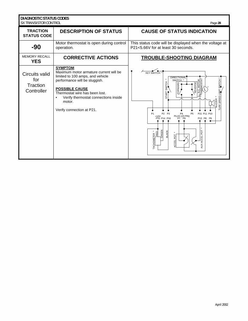
-90 Motor thermostat is open during control operation.
This status code will be displayed when the voltage at P21<5.66V for at least 30 seconds.
MEMORY RECALL YES CORRECTIVE ACTIONS TROUBLE-SHOOTING DIAGRAM
Circuits valid
for Traction
Controller
SYMPTOM Maximum motor armature current will be limited to 100 amps, and vehicle performance will be sluggish. POSSIBLE CAUSE Thermostat wire has been lost. • = Verify thermostat connections inside
motor. Verify connection at P21.
L
TUR
F SP
EED
LIM
IT S
WIT
CH
*
KEY SWITCH *
STAR
T SW
ITC
H *
DIRECTIONALSWITCH *
FOR
WAR
D
REV
ERSE
N.C
. MO
TOR
THER
MO
STAT
*
BUZZ
ER *
AUX
ACC
EL P
OT
*
ACC
EL P
OT
*
P1 P2 P3 P4 P5 P21 P11 P10
P15
TAC
HO
MET
ER *
P14+12V
P16 P7 P9 P13 P8 P6
RED
GR
EEN
BLAC
K
PLUG (23 PIN)
*
ADJUSTABLE FEATURES SX TRANSISTOR CONTROLS Page 29
April 2002
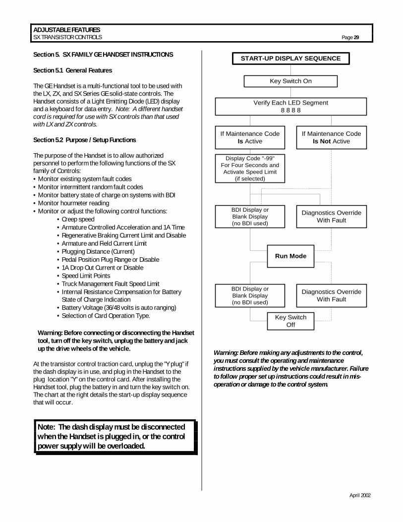
Section 5. SX FAMILY GE HANDSET INSTRUCTIONS Section 5.1 General Features The GE Handset is a multi-functional tool to be used with the LX, ZX, and SX Series GE solid-state controls. The Handset consists of a Light Emitting Diode (LED) display and a keyboard for data entry. Note: A different handset cord is required for use with SX controls than that used with LX and ZX controls. Section 5.2 Purpose / Setup Functions The purpose of the Handset is to allow authorized personnel to perform the following functions of the SX family of Controls: • =Monitor existing system fault codes • =Monitor intermittent random fault codes • =Monitor battery state of charge on systems with BDI • =Monitor hourmeter reading • =Monitor or adjust the following control functions:
• =Creep speed • =Armature Controlled Acceleration and 1A Time • =Regenerative Braking Current Limit and Disable • =Armature and Field Current Limit • =Plugging Distance (Current) • =Pedal Position Plug Range or Disable • =1A Drop Out Current or Disable • =Speed Limit Points • =Truck Management Fault Speed Limit • =Internal Resistance Compensation for Battery
State of Charge Indication • =Battery Voltage (36/48 volts is auto ranging) • =Selection of Card Operation Type.
At the transistor control traction card, unplug the "Y plug" if the dash display is in use, and plug in the Handset to the plug location "Y" on the control card. After installing the Handset tool, plug the battery in and turn the key switch on. The chart at the right details the start-up display sequence that will occur.
START-UP DISPLAY SEQUENCE
Key Switch On
Verify Each LED Segment8 8 8 8
If Maintenance CodeIs Active
If Maintenance CodeIs Not Active
Display Code "-99"For Four Seconds andActivate Speed Limit
(if selected)
BDI Display orBlank Display(no BDI used)
Diagnostics OverrideWith Fault
Run Mode
BDI Display orBlank Display(no BDI used)
Diagnostics OverrideWith Fault
Key SwitchOff
Warning: Before making any adjustments to the control, you must consult the operating and maintenance instructions supplied by the vehicle manufacturer. Failure to follow proper set up instructions could result in mis-operation or damage to the control system.
Warning: Before connecting or disconnecting the Handset tool, turn off the key switch, unplug the battery and jack up the drive wheels of the vehicle.
Note: The dash display must be disconnected when the Handset is plugged in, or the control power supply will be overloaded.
ADJUSTABLE FEATURES SX TRANSISTOR CONTROLS Page 30
April 2002
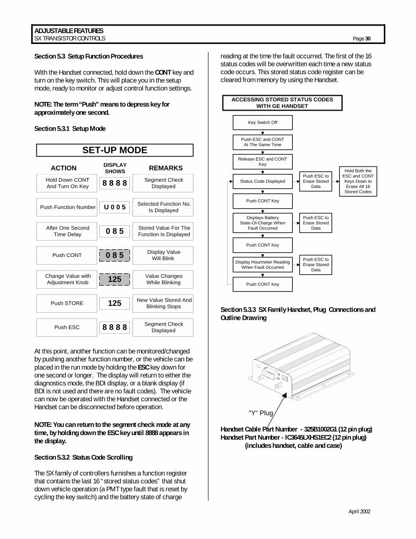
Section 5.3 Setup Function Procedures With the Handset connected, hold down the CONT key and turn on the key switch. This will place you in the setup mode, ready to monitor or adjust control function settings. NOTE: The term “Push” means to depress key for approximately one second. Section 5.3.1 Setup Mode
SET-UP MODE
Hold Down CONTAnd Turn On Key 8 8 8 8 Segment Check
Displayed
ACTION DISPLAYSHOWS REMARKS
Push Function Number U 0 0 5 Selected Function No.Is Displayed
After One SecondTime Delay 0 8 5 Stored Value For The
Function Is Displayed
Push CONT 0 8 5 Display ValueWill Blink
Change Value withAdjustment Knob
Value ChangesWhile Blinking
Push STORE 125 New Value Stored AndBlinking Stops
Push ESC 8 8 8 8 Segment CheckDisplayed
125
At this point, another function can be monitored/changed by pushing another function number, or the vehicle can be placed in the run mode by holding the ESC key down for one second or longer. The display will return to either the diagnostics mode, the BDI display, or a blank display (if BDI is not used and there are no fault codes). The vehicle can now be operated with the Handset connected or the Handset can be disconnected before operation. NOTE: You can return to the segment check mode at any time, by holding down the ESC key until 8888 appears in the display. Section 5.3.2 Status Code Scrolling The SX family of controllers furnishes a function register that contains the last 16 “stored status codes” that shut down vehicle operation (a PMT type fault that is reset by cycling the key switch) and the battery state of charge
reading at the time the fault occurred. The first of the 16 status codes will be overwritten each time a new status code occurs. This stored status code register can be cleared from memory by using the Handset.
Key Switch Off
Push ESC and CONTAt The Same Time
Release ESC and CONTKey
Status Code Displayed
Push CONT Key
Displays BatteryState-Of-Charge When
Fault Occurred
Push CONT Key
Display Hourmeter ReadingWhen Fault Occurred
Push CONT Key
ACCESSING STORED STATUS CODESWITH GE HANDSET
Push ESC toErase Stored
Data
Hold Both theESC and CONTKeys Down toErase All 16
Stored Codes
Push ESC toErase Stored
Data
Push ESC toErase Stored
Data
Section 5.3.3 SX Family Handset, Plug Connections and Outline Drawing
“Y“ Plug Handset Cable Part Number - 325B1002G1 (12 pin plug) Handset Part Number - IC3645LXHS1EC2 (12 pin plug) (includes handset, cable and case)
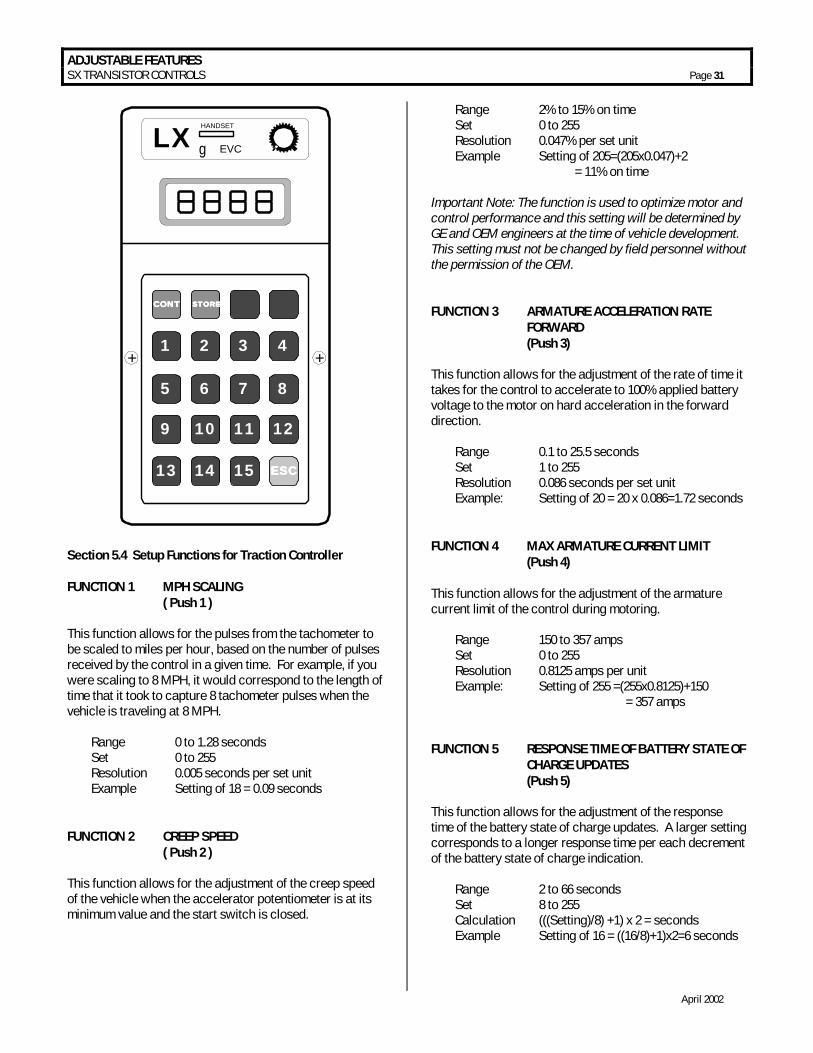
ADJUSTABLE FEATURES SX TRANSISTOR CONTROLS Page 31
April 2002
ESCESCESCESC
LX HANDSET
g EVC
CONTCONTCONTCONT STORESTORESTORESTORE
1
5
+ +
9
13
2
6
10
14
3
7
11
15
4
8
12
Section 5.4 Setup Functions for Traction Controller FUNCTION 1 MPH SCALING ( Push 1 ) This function allows for the pulses from the tachometer to be scaled to miles per hour, based on the number of pulses received by the control in a given time. For example, if you were scaling to 8 MPH, it would correspond to the length of time that it took to capture 8 tachometer pulses when the vehicle is traveling at 8 MPH. Range 0 to 1.28 seconds Set 0 to 255 Resolution 0.005 seconds per set unit Example Setting of 18 = 0.09 seconds FUNCTION 2 CREEP SPEED ( Push 2 ) This function allows for the adjustment of the creep speed of the vehicle when the accelerator potentiometer is at its minimum value and the start switch is closed.
Range 2% to 15% on time Set 0 to 255 Resolution 0.047% per set unit Example Setting of 205=(205x0.047)+2 = 11% on time Important Note: The function is used to optimize motor and control performance and this setting will be determined by GE and OEM engineers at the time of vehicle development. This setting must not be changed by field personnel without the permission of the OEM. FUNCTION 3 ARMATURE ACCELERATION RATE FORWARD (Push 3) This function allows for the adjustment of the rate of time it takes for the control to accelerate to 100% applied battery voltage to the motor on hard acceleration in the forward direction. Range 0.1 to 25.5 seconds Set 1 to 255 Resolution 0.086 seconds per set unit Example: Setting of 20 = 20 x 0.086=1.72 seconds FUNCTION 4 MAX ARMATURE CURRENT LIMIT (Push 4) This function allows for the adjustment of the armature current limit of the control during motoring. Range 150 to 357 amps Set 0 to 255 Resolution 0.8125 amps per unit Example: Setting of 255 =(255x0.8125)+150
= 357 amps FUNCTION 5 RESPONSE TIME OF BATTERY STATE OF CHARGE UPDATES (Push 5) This function allows for the adjustment of the response time of the battery state of charge updates. A larger setting corresponds to a longer response time per each decrement of the battery state of charge indication. Range 2 to 66 seconds Set 8 to 255 Calculation (((Setting)/8) +1) x 2 = seconds Example Setting of 16 = ((16/8)+1)x2=6 seconds

ADJUSTABLE FEATURES SX TRANSISTOR CONTROLS Page 32
April 2002
FUNCTION 6 ARMATURE ACCELERATION RATE REVERSE (Push 6) This function allows for the adjustment of the rate of time it takes for the control to accelerate to 100% applied battery voltage to the motor on hard acceleration in the reverse direction. Range 0.1 to 25.5 seconds Set 1 to 255 Resolution 0.086 seconds per set unit Example: Setting of 29 = 29 x 0.086 = 2.5 seconds FUNCTION 7 MIN. FIELD CURRENT ( Push 7 ) This function allows the adjustment of the field weakening level in order to set the top speed of the motor. Range 0 to 37 amps Set 51 to 255 Resolution 0.185 amps per set unit Example Setting of 82 = (82-51)x0.185 = 5.7 amps CAUTION: Do not set this function to a value less than 51. Important Note: The function is used to optimize motor and control performance and this setting will be determined by GE and OEM engineers at the time of vehicle development. This setting must not be changed by field personnel without the permission of the OEM. FUNCTION 8 MAX FIELD CURRENT ( Push 8 ) This function allows for the adjustment of the maximum field current in order to obtain the maximum torque of the motor. Range 0 to 37 amps Set 51 to 255 Resolution 0.185 amps per set unit Example Setting of 251=(251–51)x0.185=37 amps CAUTION: Do not set this function to a value less than 51. Important Note: The function is used to optimize motor and control performance and this setting will be determined by GE and OEM engineers at the time of vehicle development. This setting must not be changed by field personnel without the permission of the OEM.
FUNCTION 9 REGEN ARMATURE CURRENT LIMIT (Push 9) This function allows for the adjustment of the maximum armature current limit during regenerative braking. Range 32 to 240 amps Set 1 to 255 Resolution 0.8157 amps per set unit Example Setting of 221 = (221x0.8157) +32 = 212 amps FUNCTION 10 PLUG/REGEN FIELD CURRENT LIMIT ( Push 10 ) This function allows for the adjustment of the maximum field current limit during regenerative braking. Range 0 to 37 amps Set 51 to 255 Resolution 0.185 amps per set unit Example Setting of 180 = (180-51)x0.185 = 24 amps CAUTION: Do not set this function to a value less than 51. Important Note: The function is used to optimize motor and control performance and this setting will be determined by GE and OEM engineers at the time of vehicle development. This setting must not be changed by field personnel without the permission of the OEM. FUNCTION 11 TURF SPEED LIMIT (Push 11) This function allows for the adjustment of the top speed of the vehicle (maximum battery volts to the motor) when it is in Turf Mode. Range 100% to 0% (or creep speed) Set 51 to 170 Resolution 0.78% per set unit Example: Setting of 0 = no speed limit Setting of 170 = maximum speed reduction Setting of 122 =100%-((122-51) - (creep val/8)) x 0.78
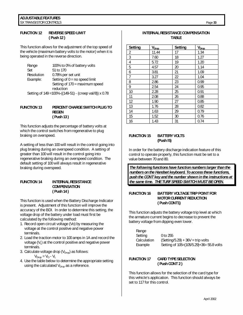
ADJUSTABLE FEATURES SX TRANSISTOR CONTROLS Page 33
April 2002
FUNCTION 12 REVERSE SPEED LIMIT ( Push 12 ) This function allows for the adjustment of the top speed of the vehicle (maximum battery volts to the motor) when it is being operated in the reverse direction. Range 100% to 0% of battery volts Set 51 to 170 Resolution 0.78% per set unit Example: Setting of 0 = no speed limit Setting of 170 = maximum speed reduction Setting of 149 =100%-((149-51) - (creep val/8)) x 0.78 FUNCTION 13 PERCENT CHARGE SWITCH PLUG TO REGEN ( Push 13 ) This function adjusts the percentage of battery volts at which the control switches from regenerative to plug braking on overspeed. A setting of less than 100 will result in the control going into plug braking during an overspeed condition. A setting of greater than 100 will result in the control going into regenerative braking during an overspeed condition. The default setting of 100 will always result in regenerative braking during overspeed. FUNCTION 14 INTERNAL RESISTANCE COMPENSATION ( Push 14 ) This function is used when the Battery Discharge Indicator is present. Adjustment of this function will improve the accuracy of the BDI. In order to determine this setting, the voltage drop of the battery under load must first be calculated by the following method: 1. Record open circuit voltage (Vo) by measuring the
voltage at the control positive and negative power terminals.
2. Load the traction motor to 100 amps in 1A and record the voltage (VL) at the control positive and negative power terminals.
3. Calculate voltage drop (VDrop) as follows: VDrop = VO - VL
4. Use the table below to determine the appropriate setting using the calculated VDrop as a reference.
INTERNAL RESISTANCE COMPENSATION TABLE
Setting VDrop Setting VDrop 2 11.44 17 1.34 3 7.60 18 1.27 4 5.72 19 1.20 5 4.57 20 1.14 6 3.81 21 1.09 7 3.27 22 1.04 8 2.86 23 0.99 9 2.54 24 0.95 10 2.28 25 0.91 11 2.08 26 0.88 12 1.90 27 0.85 13 1.76 28 0.82 14 1.63 29 0.79 15 1.52 30 0.76 16 1.43 31 0.74 FUNCTION 15 BATTERY VOLTS (Push l5) In order for the battery discharge indication feature of this control to operate properly, this function must be set to a value between 70 and 80.
FUNCTION 16 BATTERY VOLTAGE TRIP POINT FOR MOTOR CURRENT REDUCTION ( Push CONT1) This function adjusts the battery voltage trip level at which the armature current begins to decrease to prevent the battery voltage from dipping even lower. Range Setting 0 to 255 Calculation (Setting/5.29) + 36V = trip volts Example Setting of 105=(105/5.29)+36= 55.8 volts FUNCTION 17 CARD TYPE SELECTION ( Push CONT 2 ) This function allows for the selection of the card type for this vehicle’s application. This function should always be set to 117 for this control.
The following functions have function numbers larger than the numbers on the Handset keyboard. To access these functions, push the CONT key and the number shown in the instructions at the same time. THE TURF SPEED SWITCH MUST BE OPEN.
ADJUSTABLE FEATURES SX TRANSISTOR CONTROLS Page 34
April 2002
FUNCTION 18 LINE CONTACTOR DROP OUT TIME DELAY ( Push CONT 3 ) This function allows for the adjustment of the time allowable for the control to be idle before the line contactor opens. Range 0 to 25.5 seconds Setting 0 to 255 Resolution 0.1 seconds per set unit Example: Setting of 255 = 25.5 seconds FUNCTION 19 FIELD CURRENT RAMP RATE DURING
REGEN/PLUGGING ( Push CONT 4 ) This function adjusts the rate at which field current ramps to full value during regenerative or plug braking. Range 0 to 0.255 seconds Setting 0 to 255 Resolution 0.001 seconds per set unit Example: Setting of 12 = 0.012 seconds FUNCTION 20 MPH OVER SPEED LIMIT ( Push CONT 5) This function adjusts the value of the over speed limit of the control. Resolution 1 MPH per set unit Example: Setting of 28 = 28 MPH Important Note: The function is used to optimize motor and control performance and this setting will be determined by GE and OEM engineers at the time of vehicle development. This setting must not be changed by field personnel without the permission of the OEM. FUNCTION 21 RATE FIELD CHANGES IN OVERSPEED (Push CONT 6) This function adjusts how quickly the control responds to an over speed condition (as defined by the setting value of function 20). A higher setting will result in the control requiring a longer response time to an over speed condition. Range 0 to 0.255 seconds Setting 0 to 255 Resolution 0.001 seconds per set unit Example: Setting of 2 = 0.002 seconds
Important Note: The function is used to optimize motor and control performance and this setting will be determined by GE and OEM engineers at the time of vehicle development. This setting must not be changed by field personnel without the permission of the OEM. FUNCTION 23 ERROR COMPENSATION (Push CONT 8) This function is used to reduce the ripple in field current due to the interaction between motor field design and the digital field current regulation circuit. The value for this function should be set to 32. Important Note: The function is used to optimize motor and control performance and this setting will be determined by GE and OEM engineers at the time of vehicle development. This setting must not be changed by field personnel without the permission of the OEM. FUNCTION 24 FIELD WEAKENING START (or MOTOR
KNEE POINT) ( Push CONT 9) This function allows for setting the armature current at which minimum field current will be achieved.
Range 0 to 350 Amps Setting 0 to 255 Resolution 1.625 per set unit Example: Setting of 47 = 76.38 amps.
Important Note: The function is used to optimize motor and control performance and this setting will be determined by GE and OEM engineers at the time of vehicle development. This setting must not be changed by field personnel without the permission of the OEM. FUNCTION 25 MONITOR ( Push CONT 10) This function allows the monitoring of certain control functions by looking directly at the RAM of the microprocessor. Because absolute memory locations need to be known, this function should not be used without detailed instructions from the GE application engineer. To ensure optimum operation of the control, this function must be left with zero stored in this register. FUNCTION 26 RATIO OF FIELD TO ARMATURE AMPS
ADJUSTABLE FEATURES SX TRANSISTOR CONTROLS Page 35
April 2002
( Push CONT 11) This function sets the ratio between armature and field current when transitioning from minimum field to maximum field current. The setting represents the quantity of field current changed for each 1 amp of armature current changed. Max Max Resolution Example Fld Ref Change Set Per unit value If set at 3 40 .27 0 to 10 0.027 amps 0.081 amps FUNCTION 27 HOUR METER MINUTES
(Push CONT 12) This function adjusts the number of 30 second intervals registering in the hour meter. This function is typically not set by an OEM, it is usually only read from the register. Range 0 to 60 minutes Resolution 0.5 minutes per set unit Setting 0 to 120 Example Setting of 60 = 60 x 0.5 = 30 minutes FUNCTION 28 STORED STATUS CODE COUNT POINTER ( Push CONT 13) This register contains the location of the last stored status code recorded of the 16 stored status codes. These stored status codes have caused a PMT controller shutdown and/or disruption of normal vehicle operation. To determine which stored status code was the last one recorded, read the number stored in Function 28. Using the Memory Map for your logic card, match the "stored status code pointer number" [the number shown in (bold italics) in the HS (Handset) number column] on the memory map, with the number obtained from Function 28. This will be the last stored status code recorded. Note: When scrolling through the stored status code register, the register always starts at status code 1 and scrolls to status code 16. Instructions for scrolling the register are in section 5.3.2 of this instruction booklet. FUNCTION 29 HOUR METER TENS AND UNITS HOURS SET ( Push CONT 14) This function allows for the adjustment of the tens and units hours of the hour meter. Range 0 to 99
Set 0 to 99 Example 9999 Hours FUNCTION 30 HOUR METER THOUSANDS AND HUNDREDS HOURS SET ( Push CONT 15) This function allows for the adjustment of the thousands and hundreds hours of the hour meter. Range 0 to 99 Set 0 to 99 Example 9999 Hours
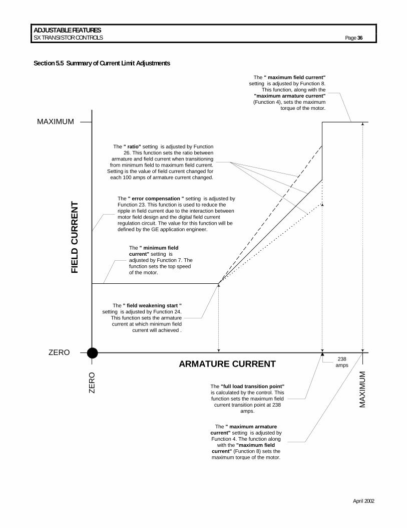
ADJUSTABLE FEATURES SX TRANSISTOR CONTROLS Page 36
April 2002
Section 5.5 Summary of Current Limit Adjustments
ZERO
MAXIMUM
ZER
O
MAX
IMU
M
FIEL
D C
URR
ENT
ARMATURE CURRENT
The " minimum fieldcurrent" setting isadjusted by Function 7. Thefunction sets the top speedof the motor.
The " maximum field current"setting is adjusted by Function 8.
This function, along with the"maximum armature current"(Function 4), sets the maximum
torque of the motor.
The " maximum armaturecurrent" setting is adjusted byFunction 4. The function along
with the "maximum fieldcurrent" (Function 8) sets themaximum torque of the motor.
The " field weakening start "setting is adjusted by Function 24.
This function sets the armaturecurrent at which minimum field
current will achieved .
The " ratio" setting is adjusted by Function26. This function sets the ratio between
armature and field current when transitioningfrom minimum field to maximum field current.
Setting is the value of field current changed foreach 100 amps of armature current changed.
The "full load transition point"is calculated by the control. Thisfunction sets the maximum field
current transition point at 238amps.
The " error compensation " setting is adjusted byFunction 23. This function is used to reduce theripple in field current due to the interaction betweenmotor field design and the digital field currentregulation circuit. The value for this function will bedefined by the GE application engineer.
238amps
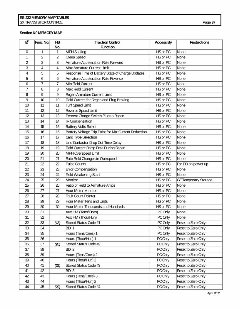
RS-232 MEMORY MAP TABLES SX TRANSISTOR CONTROL Page 37
April 2002
Section 6.0 MEMORY MAP
E2 Func No. HS No.
Traction Control Function
Access By Restrictions
0 1 1 MPH Scaling HS or PC None 1 2 2 Creep Speed HS or PC None 2 3 3 Armature Acceleration Rate Forward HS or PC None 3 4 4 Max Armature Current Limit HS or PC None 4 5 5 Response Time of Battery State of Charge Updates HS or PC None 5 6 6 Armature Acceleration Rate Reverse HS or PC None 6 7 7 Min Field Current HS or PC None 7 8 8 Max Field Current HS or PC None 8 9 9 Regen Armature Current Limit HS or PC None 9 10 10 Field Current for Regen and Plug Braking HS or PC None
10 11 11 Turf Speed Limit HS or PC None 11 12 12 Reverse Speed Limit HS or PC None 12 13 13 Percent Charge Switch Plug to Regen HS or PC None 13 14 14 IR Compensation HS or PC None 14 15 15 Battery Volts Select HS or PC None 15 16 16 Battery Voltage Trip Point for Mtr Current Reduction HS or PC None 16 17 17 Card Type Selection HS or PC None 17 18 18 Line Contactor Drop Out Time Delay HS or PC None 18 19 19 Field Current Ramp Rate During Regen HS or PC None 19 20 20 MPH Overspeed Limit HS or PC None 20 21 21 Rate Field Changes in Overspeed HS or PC None 21 22 22 Pulse Counts HS or PC For DD on power up 22 23 23 Error Compensation HS or PC None 23 24 24 Field Weakening Start HS or PC None 24 25 25 Monitor HS or PC GE Temporary Storage 25 26 26 Ratio of Field to Armature Amps HS or PC None 26 27 27 Hour Meter Minutes HS or PC None 27 28 28 Fault Count Pointer HS or PC None 28 29 29 Hour Meter Tens and Units HS or PC None 29 30 30 Hour Meter Thousands and Hundreds HS or PC None 30 31 Aux HM (Tens/Ones) PC Only None 31 32 Aux HM (Thou/Hun) PC Only None 32 33 (18) Stored Status Code #1 PC Only Reset to Zero Only 33 34 BDI 1 PC Only Reset to Zero Only 34 35 Hours (Tens/Ones) 1 PC Only Reset to Zero Only 35 36 Hours (Thou/Hun) 1 PC Only Reset to Zero Only 36 37 (20) Stored Status Code #2 PC Only Reset to Zero Only 37 38 BDI 2 PC Only Reset to Zero Only 38 39 Hours (Tens/Ones) 2 PC Only Reset to Zero Only 39 40 Hours (Thou/Hun) 2 PC Only Reset to Zero Only 40 41 (22) Stored Status Code #3 PC Only Reset to Zero Only 41 42 BDI 3 PC Only Reset to Zero Only 42 43 Hours (Tens/Ones) 3 PC Only Reset to Zero Only 43 44 Hours (Thou/Hun) 2 PC Only Reset to Zero Only 44 45 (22) Stored Status Code #4 PC Only Reset to Zero Only
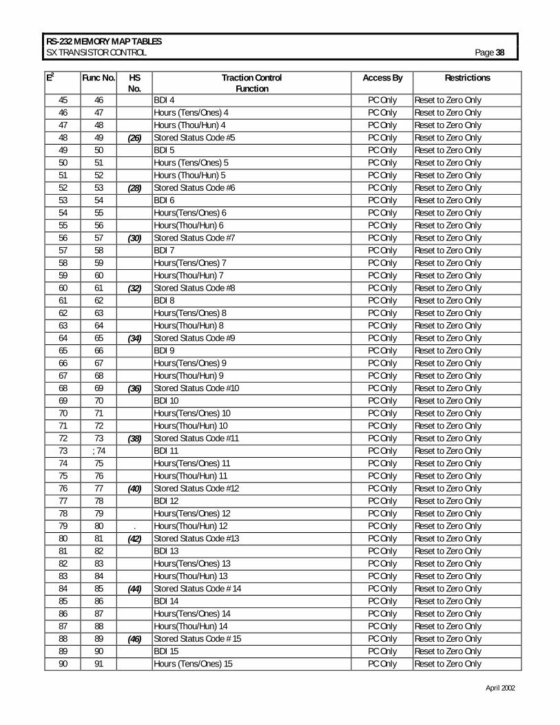
RS-232 MEMORY MAP TABLES SX TRANSISTOR CONTROL Page 38
April 2002
E2 Func No. HS No.
Traction Control Function
Access By Restrictions
45 46 BDI 4 PC Only Reset to Zero Only 46 47 Hours (Tens/Ones) 4 PC Only Reset to Zero Only 47 48 Hours (Thou/Hun) 4 PC Only Reset to Zero Only 48 49 (26) Stored Status Code #5 PC Only Reset to Zero Only 49 50 BDI 5 PC Only Reset to Zero Only 50 51 Hours (Tens/Ones) 5 PC Only Reset to Zero Only 51 52 Hours (Thou/Hun) 5 PC Only Reset to Zero Only 52 53 (28) Stored Status Code #6 PC Only Reset to Zero Only 53 54 BDI 6 PC Only Reset to Zero Only 54 55 Hours(Tens/Ones) 6 PC Only Reset to Zero Only 55 56 Hours(Thou/Hun) 6 PC Only Reset to Zero Only 56 57 (30) Stored Status Code #7 PC Only Reset to Zero Only 57 58 BDI 7 PC Only Reset to Zero Only 58 59 Hours(Tens/Ones) 7 PC Only Reset to Zero Only 59 60 Hours(Thou/Hun) 7 PC Only Reset to Zero Only 60 61 (32) Stored Status Code #8 PC Only Reset to Zero Only 61 62 BDI 8 PC Only Reset to Zero Only 62 63 Hours(Tens/Ones) 8 PC Only Reset to Zero Only 63 64 Hours(Thou/Hun) 8 PC Only Reset to Zero Only 64 65 (34) Stored Status Code #9 PC Only Reset to Zero Only 65 66 BDI 9 PC Only Reset to Zero Only 66 67 Hours(Tens/Ones) 9 PC Only Reset to Zero Only 67 68 Hours(Thou/Hun) 9 PC Only Reset to Zero Only 68 69 (36) Stored Status Code #10 PC Only Reset to Zero Only 69 70 BDI 10 PC Only Reset to Zero Only 70 71 Hours(Tens/Ones) 10 PC Only Reset to Zero Only 71 72 Hours(Thou/Hun) 10 PC Only Reset to Zero Only 72 73 (38) Stored Status Code #11 PC Only Reset to Zero Only 73 ; 74 BDI 11 PC Only Reset to Zero Only 74 75 Hours(Tens/Ones) 11 PC Only Reset to Zero Only 75 76 Hours(Thou/Hun) 11 PC Only Reset to Zero Only 76 77 (40) Stored Status Code #12 PC Only Reset to Zero Only 77 78 BDI 12 PC Only Reset to Zero Only 78 79 Hours(Tens/Ones) 12 PC Only Reset to Zero Only 79 80 . Hours(Thou/Hun) 12 PC Only Reset to Zero Only 80 81 (42) Stored Status Code #13 PC Only Reset to Zero Only 81 82 BDI 13 PC Only Reset to Zero Only 82 83 Hours(Tens/Ones) 13 PC Only Reset to Zero Only 83 84 Hours(Thou/Hun) 13 PC Only Reset to Zero Only 84 85 (44) Stored Status Code # 14 PC Only Reset to Zero Only 85 86 BDI 14 PC Only Reset to Zero Only 86 87 Hours(Tens/Ones) 14 PC Only Reset to Zero Only 87 88 Hours(Thou/Hun) 14 PC Only Reset to Zero Only 88 89 (46) Stored Status Code # 15 PC Only Reset to Zero Only 89 90 BDI 15 PC Only Reset to Zero Only 90 91 Hours (Tens/Ones) 15 PC Only Reset to Zero Only
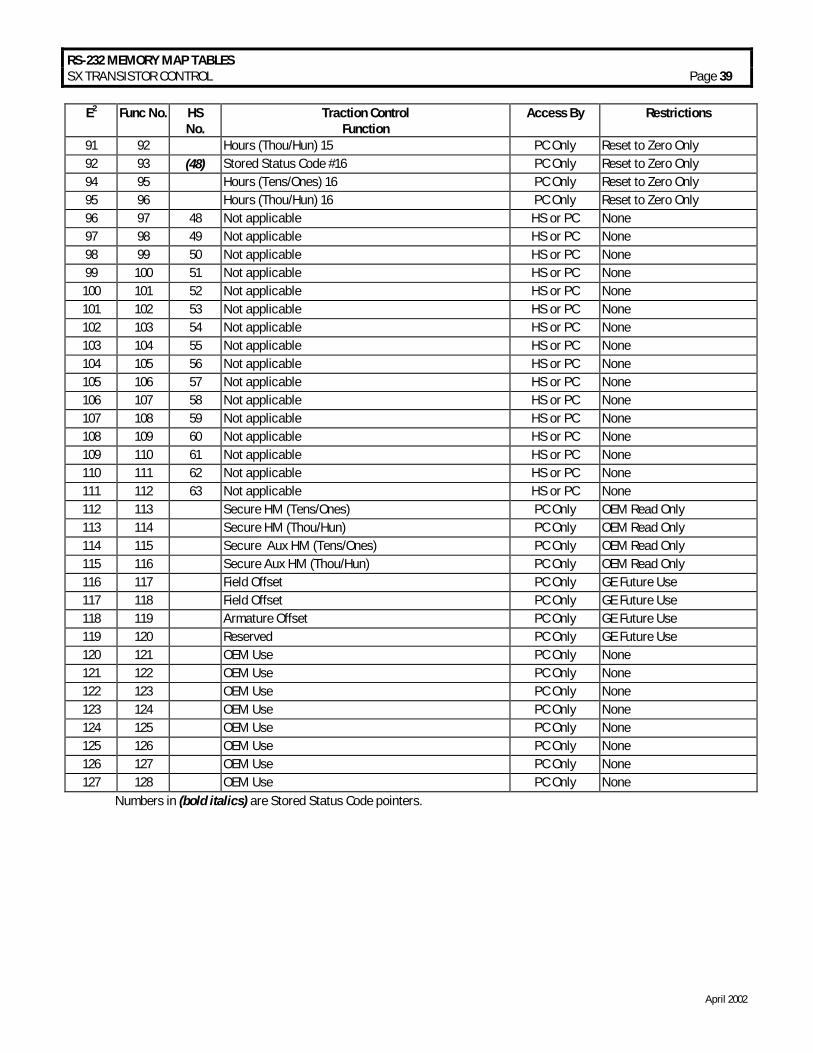
RS-232 MEMORY MAP TABLES SX TRANSISTOR CONTROL Page 39
April 2002
E2 Func No. HS No.
Traction Control Function
Access By Restrictions
91 92 Hours (Thou/Hun) 15 PC Only Reset to Zero Only 92 93 (48) Stored Status Code #16 PC Only Reset to Zero Only 94 95 Hours (Tens/Ones) 16 PC Only Reset to Zero Only 95 96 Hours (Thou/Hun) 16 PC Only Reset to Zero Only 96 97 48 Not applicable HS or PC None 97 98 49 Not applicable HS or PC None 98 99 50 Not applicable HS or PC None 99 100 51 Not applicable HS or PC None 100 101 52 Not applicable HS or PC None 101 102 53 Not applicable HS or PC None 102 103 54 Not applicable HS or PC None 103 104 55 Not applicable HS or PC None 104 105 56 Not applicable HS or PC None 105 106 57 Not applicable HS or PC None 106 107 58 Not applicable HS or PC None 107 108 59 Not applicable HS or PC None 108 109 60 Not applicable HS or PC None 109 110 61 Not applicable HS or PC None 110 111 62 Not applicable HS or PC None 111 112 63 Not applicable HS or PC None 112 113 Secure HM (Tens/Ones) PC Only OEM Read Only 113 114 Secure HM (Thou/Hun) PC Only OEM Read Only 114 115 Secure Aux HM (Tens/Ones) PC Only OEM Read Only 115 116 Secure Aux HM (Thou/Hun) PC Only OEM Read Only 116 117 Field Offset PC Only GE Future Use 117 118 Field Offset PC Only GE Future Use 118 119 Armature Offset PC Only GE Future Use 119 120 Reserved PC Only GE Future Use 120 121 OEM Use PC Only None 121 122 OEM Use PC Only None 122 123 OEM Use PC Only None 123 124 OEM Use PC Only None 124 125 OEM Use PC Only None 125 126 OEM Use PC Only None 126 127 OEM Use PC Only None 127 128 OEM Use PC Only None
Numbers in (bold italics) are Stored Status Code pointers.