Embed Size (px)
Citation preview

INSTALLATION AND OPERATION SX TRANSISTOR CONTROL Page 1
November 1999
SEPARATELY EXCITED (SX) TRANSISTORIZED TRACTION MOTOR CONTROL AND SERIES PUMP MOTOR CONTROL
INSTALLATION AND OPERATION MANUAL (IC3645SR4W606X1 and IC3645SP4U450X2)
Note: The information contained herein is intended to assist OEM's, Dealers and Users of electric vehicles in the application, installation and service of GE solid-state controllers. This manual does not purport to cover all variations in OEM vehicle types. Nor does it provide for every possible contingency to be met involving vehicle installation, operation or maintenance. For additional information and/or problem resolution, please refer the matter to the OEM vehicle manufacturer through his normal field service channels. Do not contact GE directly for this assistance.
Copyright by General Electric Company November 1999
Section 1.0 INTRODUCTION ........................................................................................................................................................ 4 1.1 Motor Characteristics .............................................................................................................. 4 1.2 Solid-State Reversing............................................................................................................... 5 1.3 Flexible System Application..................................................................................................... 5 1.4 More Features with Fewer Components ................................................................................ 5 Section 2.0 FEATURES OF SX FAMILY OF MOTOR CONTROLLERS .................................................................................... 6 2.1 Performance.............................................................................................................................. 6 2.1.1 Oscillator Card Features .................................................................................................. 6 2.1.1.a Standard Operation .................................................................................................. 6 2.1.1.b Creep Speed............................................................................................................... 6 2.1.1.c Controlled Acceleration and 1A Time..................................................................... 6 2.1.2 Current Limit ...................................................................................................................... 6 2.1.3 Braking ............................................................................................................................... 6 2.1.3.a Plug Braking .............................................................................................................. 6 2.1.3.b Regenerative Braking to Zero Speed...................................................................... 6
Table of Contents

INSTALLATION AND OPERATION SX TRANSISTOR CONTROL Page 2
November 1999
2.1.3.c Pedal Position Plug Braking .................................................................................... 6 2.1.3.d Auto Braking.............................................................................................................. 6 2.1.3.e Brake Pedal Regenerative Braking ......................................................................... 6 2.1.4 Auxiliary Speed Control.................................................................................................... 6 2.1.4.a Field Weakening................................................................................................................ 6 2.1.4.b Speed Limits ...................................................................................................................... 7 2.1.5 Ramp Operation ................................................................................................................ 7 2.1.5.a Ramp Start ................................................................................................................. 7 2.1.5.b Anti-Rollback ............................................................................................................. 7 2.1.6 Steer Pump Contactor Time Delay ................................................................................. 7 2.1.7 On-Board Coil Drivers and Internal Coil Suppression ................................................. 7 2.2 System Protective Override ..................................................................................................... 7 2.2.1 Static Return to Off (SRO) ............................................................................................... 7 2.2.2 Accelerator Volts Hold Off ............................................................................................... 7 2.2.3 Pulse Monitor Trip (PMT)................................................................................................. 7 2.2.4 Thermal Protector (TP)................................... .................................................................. 7 2.2.5 Low Voltage .................................... .................................................................................. 8 2.3 Diagnostics................................................ ................................................................................ 8 2.3.1 Systems Diagnostics...................................... .................................................................. 8 2.3.2 Status Codes...................................................................................................................... 8 2.3.2.a Standard Codes......................................................................................................... 8 2.3.2.b Stored Codes ......................................... ................................................................... 8 2.3.3 Hourmeter Readings ...................................... .................................................................. 8 2.3.3.a Maintenance Alert and Speed Limit .................... .................................................. 8 2.3.4 Battery Discharge Indication (BDI)....................... ......................................................... 8 2.3.4.a Internal Resistance Compensation ..................... ........................................................... 8 2.3.5 Handset ................................................. ............................................................................ 8 2.3.6 RS-232 Communication Port ............................... ............................................................ 9 2.3.6.a Dash Display Interaction Modes ................... ............................................................... 9 2.3.7 Circuit Board Coil Driver Modules........................ .......................................................... 9
2.3.8 Truck Management Module (TMM) ............................................................................... 9 2.4 Hydraulic Pump Control................................................ ........................................................... 9
Section 3.0 ORDERING INFORMATION, ELEMENTARY AND OUTLINE DRAWINGS...................................................... 10 3.1 Ordering Information for Separately Excited Controls................................................................. 10 3.2 Outline: SX-4 and SR-4 Package Size............................................................................................. 11
3.3 Outline: SX-3 and SR-3 Package Size............................................................................................. 12 3.4 Traction Elementary ......................................................................................................................... 13 3.5 Pump Elementary .............................................................................................................................. 14 3.6 Traction and Pump Control Input / Output List ............................................................................. 15 Section 4.0 TROUBLESHOOTING AND DIAGNOSTIC STATUS CODES.............................................................................. 16
4.1 General Maintenance Instructions................................................................................................. 16
4.2 Cable Routing and Separation ............................................................................................... 16 4.2.1 Application Responsibility ............................................................................................... 16 4.2.2 Signal/Power Level Definitions ............................................................................................... 16 4.2.2.a Low Level Signals (Level L) .............................................................................................. 16
Table of Contents ( Continued )
INSTALLATION AND OPERATION SX TRANSISTOR CONTROL Page 3
November 1999
4.2.2.b High Level Signals (Level H)............................................................................................. 17 4.2.2.c Medium-Power Signals (Level MP) ................................................................................ 17 4.2.2.d High-Power Signals (Level HP) ....................................................................................... 17 4.2.3 Cable Spacing Guidelines ........................................................................................................ 17 4.2.3.a General Cable Spacing..................................................................................................... 17 4.2.4 Cabling for Vehicle Retrofits.................................................................................................... 17 4.2.5 RF Interference.......................................................................................................................... 17 4.2.6 Suppression............................................................................................................................... 17
4.3 Recommended Lubrication of Pins and Sockets Prior to Installation........................................ 18 4.4 General Troubleshooting Instructions ........................................................................................... 19 4.5 Traction Controller Status Codes ................................................................................................... 20-35 4.6 TMM Module Status Codes............................................................................................................. 36-40
4.7 Pump Control Status Codes............................................................................................................. 41-49 Section 5.0 TRUCK MANAGEMENT MODULE (TMM)............................................................................................................ 50 5.1 General Features .............................................................................................................................. 50 5.2 Operation ...................................................... .................................................................................... 50 5.3 Installation.................................................... ..................................................................................... 50 5.4 Connection Diagrams....................................................................................................................... 50 5.4.1 TMM7A Card Connections ...................................................................................................... 50 5.4.2 TMM7A Typical Brush Wear Sensor Connections ............ ................................................. 50 5.4.3 TMM Pump Control Connections ........................................................................................... 51 5.4.4 Typical Brush Wear Sensor Connections For Pump Control.. ............................................ 51 5.5 TMM7A Outline Drawings ............................................................................................................... 51 Section 6.0 SX FAMILY - GE HANDSET INSTRUCTIONS ...................................................................................................... 52 6.1 General Features .............................................................................................................................. 52 6.2 Purpose/Setup Functions ............................................................................................................... 52 6.3 Setup Function Procedures ................................ ............................................................................ 53 6.3.1 Setup Mode ............................................ .................................................................................. 53 6.3.2 Status Code Scrolling............................................................................................................... 53 6.3.3 SX Handset Plug Connections & Outline Drawing.... ........................................................... 53
6.4 Setup Functions for Traction Controller .. ..................................................................................... 54-59 6.5 Summary of Current Limit Adjustments ......................................................................................... 60 6.6 Setup Functions for Hydraulic Pump Controller . ......................................................................... 61-63
Section 7.0 DASH DISPLAYS................................................. ...................................................................................................... 64 7.1 Application ............................................. ............................................................................................. 64 7.2 Standard Dash Displays .................................. .................................................................................. 64 7.3 Interactive Dash Displays................................................................................................................... 64 7.4 Start-up Display Sequence ................................................................................................................ 65 7.5 Outline Drawings ........................................ ........................................................................................ 65 Section 8.0 MEMORY MAPS........................................................................................................................................................ 66 8.1 Typical Memory Map for Traction Control .................................................................................... 66-68
Table of Contents ( Continued )

BASIC OPERATION AND FEATURES SX TRANSISTOR CONTROL Page 4
November 1999
Section 1. INTRODUCTION
Section 1.1 Motor Characteristics The level of sophistication in the controllability of traction motors has changed greatly over the past several years. Vehicle manufacturers and users are continuing to expect more value and flexibility in electric vehicle motor and control systems as they are applied today. In order to respond to these market demands, traction system designers have been forced to develop new approaches to reduce cost and improve functions and features of the overall system. Development is being done in a multi-generational format that allows the market to take advantage of today’s technology, while looking forward to new advances on the horizon. GE has introduced a second generation system using separately excited DC shunt wound motors. The separately excited DC motor system offers many of the features that are generally found on the advanced AC systems. Historically, most electric vehicles have relied have on series motor designs because of their ability to produce very high levels of torque at low speeds. But, as the demand for high efficiency systems increases, i.e., systems that are more closely applied to customers’ specific torque requirements, shunt motors are now often being considered over series motors. In most applications, by independently controlling the field and armature currents in the separately excited motor, the best attributes of both the series and the shunt wound motors can be combined.
NO LO
AD CU
RREN
T
FULL
LOAD
CURR
ENT
STAR
TING
CURR
ENT
ARMATURE CURRENTFigure 1
SPEED
TORQUE
As shown in from the typical performance curves of Figure 1, the high torque at low speed characteristic of the series motor is evident. In a shunt motor, the field is connected directly across the voltage source and is therefore independent of variations in load and armature current. If field strength is held constant, the torque developed will vary directly with the armature current. If the mechanical load on the motor increases, the motor slows down, reducing the back EMF (which depends on the speed, as well as the constant field strength). The reduced back EMF allows the armature
current to increase, providing the greater torque needed to drive the increased mechanical load. If the mechanical load is decreased, the process reverses. The motor speed and the back EMF increase, while the armature current and the torque developed decrease. Thus, whenever the load changes, the speed changes also, until the motor is again in electrical balance. In a shunt motor, the variation of speed from no load to normal full load on level ground is less than 10%. For this reason, shunt motors are considered to be constant speed motors (Figure 2).
NO
LOAD
CURR
ENT FULL
LOAD
CURR
ENT
STAR
TING
CURR
ENT
ARMATURE CURRENTFigure 2
SPEED
TORQUE
In the separately excited motor, the motor is operated as a fixed field shunt motor in the normal running range. However, when additional torque is required, for example, to climb non-level terrain, such as ramps and the like, the field current is increased to provide the higher level of torque. In most cases, the armature to field ampere turn ratio can be very similar to that of a comparable size series motor (Figure 3.)
NO LO
AD CU
RREN
T FULL
LOAD
CURR
ENT
STAR
TING
CURR
ENT
ARMATURE CURRENTFigure 3
SPEED
TORQUE
Aside from the constant horsepower characteristics described above, there are many other features that provide increased performance and lower cost. The

BASIC OPERATION AND FEATURES SX TRANSISTOR CONTROL Page 5
November 1999
following description provides a brief introduction to examples of some of these features. Section 1. 2 Solid-State Reversing The direction of armature rotation on a shunt motor is determined by the direction in which current flows through the field windings. Because of the of the shunt motor field only typically requires about 10% of the armature current at full torque, it is normally cost effective to replace the double-pole, double-throw reversing contactor with a low power transistor H-Bridge circuit (Figure 4).
By energizing the transistors in pairs, current can be made to flow in either direction in the field. The armature control circuit typically operates at 12KHZ to 15KHZ, a frequency range normally above human hearing. This high frequency coupled with the elimination of directional contactors, provides very quiet vehicle operation. The field control circuits typically operate at 2 KHZ. The line contactor is normally the only contactor required for the shunt motor traction circuit. This contactor is used for both pre-charge of the line capacitors and for emergency shut down of the motor circuit, in case of problems that would cause a full motor torque condition. The line can be energized and de-energized by the various logic combinations of the vehicle, i.e. activate on key, seat or start switch closure, and de-energize on time out of idle vehicle. Again, these options add to the quiet operation of the vehicle. Section 1. 3 Flexible System Application Because the shunt motor controller has the ability to control both the armature and field circuits independently, the system can normally be adjusted for maximum system efficiencies at certain operating parameters. Generally speaking, with the ability of independent field and
armature, the motor performance curve can be maximized through proper control application. Section 1. 4 More Features with Fewer Components Field weakening with a series wound motor is accomplished by placing a resistor in parallel with the field winding of the motor. Bypassing some of the current flowing in the field into the resistor causes the field current to be less, or weakened. With the field weakened, the motor speed will increase, giving the effect of “overdrive”. To change the “overdrive speed”, it is necessary to change
the resistor value. In a separately excited motor, independent control of the field current provides for infinite adjustments of “overdrive” levels, between motor base speed and maximum weak field. The desirability of this feature is enhanced by the elimination of the contactor and resistor required for field weakening with a series motor. With a separately excited motor, overhauling speed limit, or downhill speed, will also be more constant. By its nature, the shunt motor will try to maintain a constant speed downhill. This characteristic can be enhanced by increasing the field strength with the control. Overhauling load control works in just the opposite way of field weakening, armature rotation slows with the increase of current in the field. Regenerative braking (braking energy returned to the
battery) may be accomplished completely with solid-state technology. The main advantage of regenerative braking is increased motor life. Motor current is reduced by 50% or more during braking while maintaining the same braking torque as electrical braking with a diode clamp around the armature. The lower current translates into longer brush life and reduced motor heating. Solid state regenerative braking also eliminates a power diode, current sensor and contactor from the circuit. For GE, the future is now as we make available a new generation of electric traction motor systems for electric vehicles having separately excited DC shunt motors and controls. Features that were once thought to be only available on future AC or brushless DC technology vehicles systems are now achievable and affordable.
FUSE
LINE
CAPARM F2F1
Q3
Q4
Q5
Q6
Q1
POS
NEG
Figure 4
A1 +
A2 -Q2

BASIC OPERATION AND FEATURES SX TRANSISTOR CONTROL Page 6
November 1999
Section 2. FEATURES OF SX FAMILY OF TRANSISTOR MOTOR CONTROLLERS Section 2.1 Performance Section 2.1.1 Oscillator Card Features Section 2.1.1.a Standard Operation With the accelerator at maximum ohms or volts, the creep speed can be adjusted by Function 2 of the Handset or a trimpot. The field control section allows the adjustment of the field weakening level in order to set the top speed of the motor. This top speed function (Minimum Field Current) is enabled when the armature current is less than the value set by Function 24 and the accelerator input voltage is less than 1 volt. Top Speed can be adjusted by Function 7 of the Handset or a trimpot. The percent on-time has a range of approximately 0 to 100 percent. The SX controllers operate at a constant frequency and the percent on-time is controlled by the pulse width of the voltage / current applied to the motor circuits. Section 2.1.1.b Creep Speed With the accelerator at maximum ohms or volts (approximately 3.7 to 3.5 VDC), the creep speed can be adjusted by Function 2 of the Handset. At creep speed, the ON time can decrease to approximately 5%, with the OFF time at approximately 95%. At full transistor operation, this condition will be reversed (short OFF time, long ON time). This variation of ON and OFF time of the oscillator varies the voltage applied to the motor, thereby varying the speed of the motor for a given load. Section 2.1.1.c Control Acceleration This feature allows for adjustment of the rate of time it takes for the control to accelerate to 100% applied battery voltage to the motor on hard acceleration. Armature C/A is adjusted by Function 3 from 0.1 to 22 seconds. Section 2.1.2 Current Limit This circuit monitors motor current by utilizing sensors in series with the armature and field windings. The information detected by the sensor is fed back to the card so that current may be limited to a pre-set value. If heavy load currents are detected, this circuit overrides the oscillator and limits the average current to a value set by Function 4 and Function 8 of the Handset. The C/L setting is based on the maximum thermal rating of the control. Because of the flyback current through 3REC, the motor current is usually greater than battery current, except at 100% ON time.
Section 2.1.3 Braking Section 2.1.3.a Plug Braking Section 2.1.3.b Regenerative Braking to Zero Speed
Slow down is accomplished when reversing direction by providing a small amount of retarding torque for deceleration. If the vehicle is moving, and the directional lever is moved from one direction to the other, the regen signal is initiated. Once the regen signal has been initiated, the field current is increased (armature circuit shown in Figure 5). Armature current is
regulated to the regen current limit as set by Function 9. As the vehicle slows down, the field current continues to increase, and transistor Q2 begins to chop. The field current will increase until it reaches a preset value set by Function 10, and transistor Q2 on-time will increase until it reaches 100% on-time. Once both of the above conditions have been met, and regen current limit can no longer be maintained, the braking function is canceled. The fields will then reverse, and the control reverts back to motoring. Part of the energy produced by the motor during regen is returned to the battery, and part is dumped in the motor as heat. Section 2.1.3.c Pedal Position Plug Braking This feature allows control of the plugging distance based on pedal position when there has been a “directional switch" change. Pedal position will reduce the regenerative current to the "value set by this function" as the accelerator is returned to the creep speed position. Maximum regen current is obtained with the accelerator in the top speed position. Section 2.1.3.d Auto Braking This feature is enabled by initiating a "neutral position" using either the directional switch or the accelerator switch. Once activated, Auto Braking operates similar to Pedal Position Plug Braking and is adjusted by using Function 21 of the Handset. Section 2.1.4 Auxiliary Speed Control Section 2.1.4.a Field Weakening This function allows the adjustment of the field weakening level in order to set the top speed of the motor. The function is enabled when the armature current is less than the value set by Function 24 and the accelerator input voltage is less than 1 volt. It is important to note that this function is used
ARM
Q1
Q2
Figure 5
BASIC OPERATION AND FEATURES SX TRANSISTOR CONTROL Page 7
November 1999
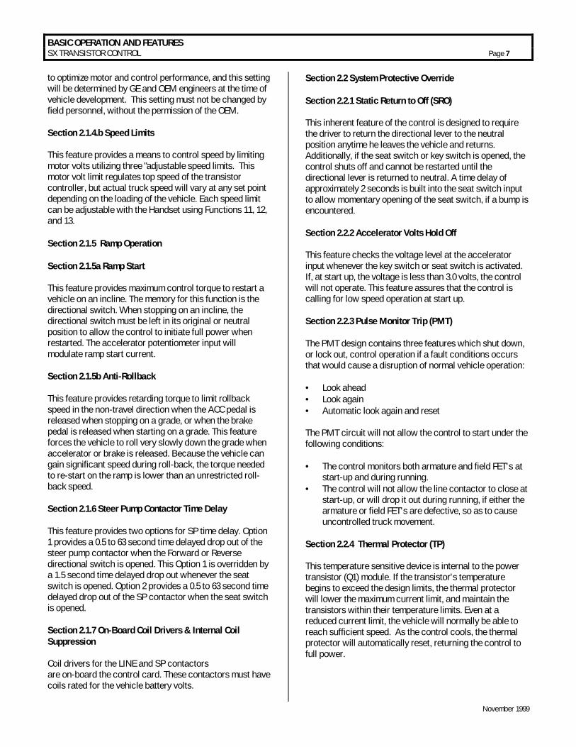
to optimize motor and control performance, and this setting will be determined by GE and OEM engineers at the time of vehicle development. This setting must not be changed by field personnel, without the permission of the OEM. Section 2.1.4.b Speed Limits This feature provides a means to control speed by limiting motor volts utilizing three "adjustable speed limits. This motor volt limit regulates top speed of the transistor controller, but actual truck speed will vary at any set point depending on the loading of the vehicle. Each speed limit can be adjustable with the Handset using Functions 11, 12, and 13. Section 2.1.5 Ramp Operation Section 2.1.5a Ramp Start This feature provides maximum control torque to restart a vehicle on an incline. The memory for this function is the directional switch. When stopping on an incline, the directional switch must be left in its original or neutral position to allow the control to initiate full power when restarted. The accelerator potentiometer input will modulate ramp start current. Section 2.1.5b Anti-Rollback This feature provides retarding torque to limit rollback speed in the non-travel direction when the ACC pedal is released when stopping on a grade, or when the brake pedal is released when starting on a grade. This feature forces the vehicle to roll very slowly down the grade when accelerator or brake is released. Because the vehicle can gain significant speed during roll-back, the torque needed to re-start on the ramp is lower than an unrestricted roll-back speed. Section 2.1.6 Steer Pump Contactor Time Delay This feature provides two options for SP time delay. Option 1 provides a 0.5 to 63 second time delayed drop out of the steer pump contactor when the Forward or Reverse directional switch is opened. This Option 1 is overridden by a 1.5 second time delayed drop out whenever the seat switch is opened. Option 2 provides a 0.5 to 63 second time delayed drop out of the SP contactor when the seat switch is opened. Section 2.1.7 On-Board Coil Drivers & Internal Coil Suppression Coil drivers for the LINE and SP contactors are on-board the control card. These contactors must have coils rated for the vehicle battery volts.
Section 2.2 System Protective Override Section 2.2.1 Static Return to Off (SRO) This inherent feature of the control is designed to require the driver to return the directional lever to the neutral position anytime he leaves the vehicle and returns. Additionally, if the seat switch or key switch is opened, the control shuts off and cannot be restarted until the directional lever is returned to neutral. A time delay of approximately 2 seconds is built into the seat switch input to allow momentary opening of the seat switch, if a bump is encountered. Section 2.2.2 Accelerator Volts Hold Off This feature checks the voltage level at the accelerator input whenever the key switch or seat switch is activated. If, at start up, the voltage is less than 3.0 volts, the control will not operate. This feature assures that the control is calling for low speed operation at start up. Section 2.2.3 Pulse Monitor Trip (PMT) The PMT design contains three features which shut down, or lock out, control operation if a fault conditions occurs that would cause a disruption of normal vehicle operation: • = Look ahead • = Look again • = Automatic look again and reset The PMT circuit will not allow the control to start under the following conditions: • = The control monitors both armature and field FET's at
start-up and during running. • = The control will not allow the line contactor to close at
start-up, or will drop it out during running, if either the armature or field FET's are defective, so as to cause uncontrolled truck movement.
Section 2.2.4 Thermal Protector (TP) This temperature sensitive device is internal to the power transistor (Q1) module. If the transistor's temperature begins to exceed the design limits, the thermal protector will lower the maximum current limit, and maintain the transistors within their temperature limits. Even at a reduced current limit, the vehicle will normally be able to reach sufficient speed. As the control cools, the thermal protector will automatically reset, returning the control to full power.
BASIC OPERATION AND FEATURES SX TRANSISTOR CONTROL Page 8
November 1999
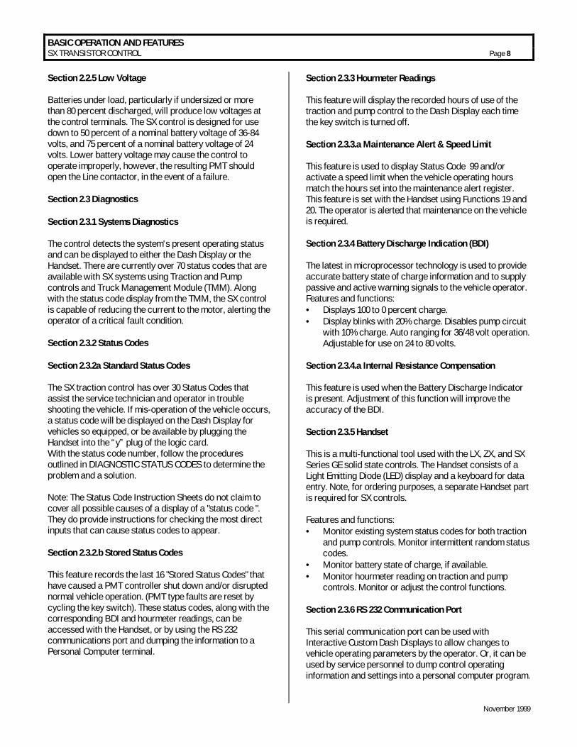
Section 2.2.5 Low Voltage Batteries under load, particularly if undersized or more than 80 percent discharged, will produce low voltages at the control terminals. The SX control is designed for use down to 50 percent of a nominal battery voltage of 36-84 volts, and 75 percent of a nominal battery voltage of 24 volts. Lower battery voltage may cause the control to operate improperly, however, the resulting PMT should open the Line contactor, in the event of a failure. Section 2.3 Diagnostics Section 2.3.1 Systems Diagnostics The control detects the system's present operating status and can be displayed to either the Dash Display or the Handset. There are currently over 70 status codes that are available with SX systems using Traction and Pump controls and Truck Management Module (TMM). Along with the status code display from the TMM, the SX control is capable of reducing the current to the motor, alerting the operator of a critical fault condition. Section 2.3.2 Status Codes Section 2.3.2a Standard Status Codes The SX traction control has over 30 Status Codes that assist the service technician and operator in trouble shooting the vehicle. If mis-operation of the vehicle occurs, a status code will be displayed on the Dash Display for vehicles so equipped, or be available by plugging the Handset into the “y” plug of the logic card. With the status code number, follow the procedures outlined in DIAGNOSTIC STATUS CODES to determine the problem and a solution. Note: The Status Code Instruction Sheets do not claim to cover all possible causes of a display of a "status code ". They do provide instructions for checking the most direct inputs that can cause status codes to appear. Section 2.3.2.b Stored Status Codes This feature records the last 16 "Stored Status Codes" that have caused a PMT controller shut down and/or disrupted normal vehicle operation. (PMT type faults are reset by cycling the key switch). These status codes, along with the corresponding BDI and hourmeter readings, can be accessed with the Handset, or by using the RS 232 communications port and dumping the information to a Personal Computer terminal.
Section 2.3.3 Hourmeter Readings This feature will display the recorded hours of use of the traction and pump control to the Dash Display each time the key switch is turned off. Section 2.3.3.a Maintenance Alert & Speed Limit This feature is used to display Status Code 99 and/or activate a speed limit when the vehicle operating hours match the hours set into the maintenance alert register. This feature is set with the Handset using Functions 19 and 20. The operator is alerted that maintenance on the vehicle is required. Section 2.3.4 Battery Discharge Indication (BDI) The latest in microprocessor technology is used to provide accurate battery state of charge information and to supply passive and active warning signals to the vehicle operator. Features and functions: • = Displays 100 to 0 percent charge. • = Display blinks with 20% charge. Disables pump circuit
with 10% charge. Auto ranging for 36/48 volt operation. Adjustable for use on 24 to 80 volts.
Section 2.3.4.a Internal Resistance Compensation This feature is used when the Battery Discharge Indicator is present. Adjustment of this function will improve the accuracy of the BDI. Section 2.3.5 Handset This is a multi-functional tool used with the LX, ZX, and SX Series GE solid state controls. The Handset consists of a Light Emitting Diode (LED) display and a keyboard for data entry. Note, for ordering purposes, a separate Handset part is required for SX controls. Features and functions: • = Monitor existing system status codes for both traction
and pump controls. Monitor intermittent random status codes.
• = Monitor battery state of charge, if available. • = Monitor hourmeter reading on traction and pump
controls. Monitor or adjust the control functions. Section 2.3.6 RS 232 Communication Port This serial communication port can be used with Interactive Custom Dash Displays to allow changes to vehicle operating parameters by the operator. Or, it can be used by service personnel to dump control operating information and settings into a personal computer program.
BASIC OPERATION AND FEATURES SX TRANSISTOR CONTROL Page 9
November 1999
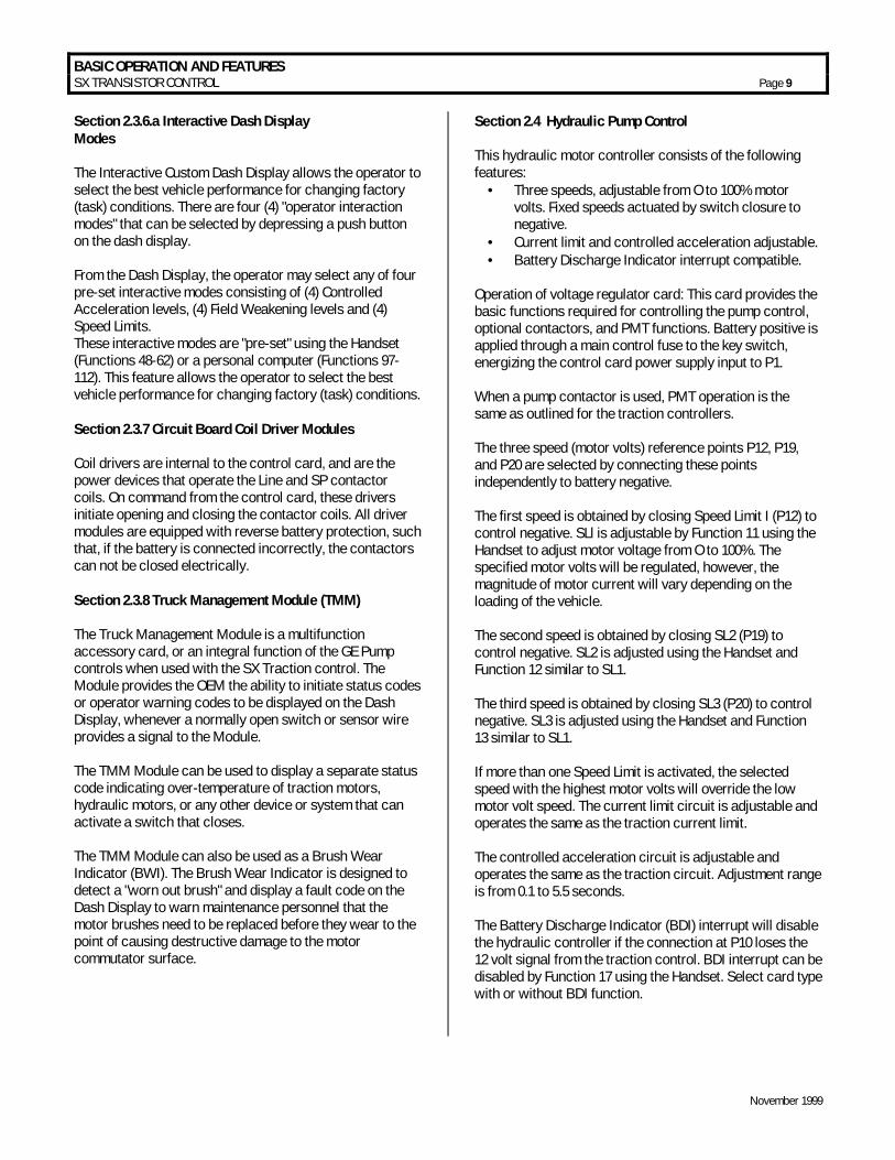
Section 2.3.6.a Interactive Dash Display Modes The Interactive Custom Dash Display allows the operator to select the best vehicle performance for changing factory (task) conditions. There are four (4) "operator interaction modes" that can be selected by depressing a push button on the dash display. From the Dash Display, the operator may select any of four pre-set interactive modes consisting of (4) Controlled Acceleration levels, (4) Field Weakening levels and (4) Speed Limits. These interactive modes are "pre-set" using the Handset (Functions 48-62) or a personal computer (Functions 97- 112). This feature allows the operator to select the best vehicle performance for changing factory (task) conditions. Section 2.3.7 Circuit Board Coil Driver Modules Coil drivers are internal to the control card, and are the power devices that operate the Line and SP contactor coils. On command from the control card, these drivers initiate opening and closing the contactor coils. All driver modules are equipped with reverse battery protection, such that, if the battery is connected incorrectly, the contactors can not be closed electrically. Section 2.3.8 Truck Management Module (TMM) The Truck Management Module is a multifunction accessory card, or an integral function of the GE Pump controls when used with the SX Traction control. The Module provides the OEM the ability to initiate status codes or operator warning codes to be displayed on the Dash Display, whenever a normally open switch or sensor wire provides a signal to the Module. The TMM Module can be used to display a separate status code indicating over-temperature of traction motors, hydraulic motors, or any other device or system that can activate a switch that closes. The TMM Module can also be used as a Brush Wear Indicator (BWI). The Brush Wear Indicator is designed to detect a "worn out brush" and display a fault code on the Dash Display to warn maintenance personnel that the motor brushes need to be replaced before they wear to the point of causing destructive damage to the motor commutator surface.
Section 2.4 Hydraulic Pump Control This hydraulic motor controller consists of the following features:
• = Three speeds, adjustable from O to 100% motor volts. Fixed speeds actuated by switch closure to negative.
• = Current limit and controlled acceleration adjustable. • = Battery Discharge Indicator interrupt compatible.
Operation of voltage regulator card: This card provides the basic functions required for controlling the pump control, optional contactors, and PMT functions. Battery positive is applied through a main control fuse to the key switch, energizing the control card power supply input to P1. When a pump contactor is used, PMT operation is the same as outlined for the traction controllers. The three speed (motor volts) reference points P12, P19, and P20 are selected by connecting these points independently to battery negative. The first speed is obtained by closing Speed Limit I (P12) to control negative. SLl is adjustable by Function 11 using the Handset to adjust motor voltage from O to 100%. The specified motor volts will be regulated, however, the magnitude of motor current will vary depending on the loading of the vehicle. The second speed is obtained by closing SL2 (P19) to control negative. SL2 is adjusted using the Handset and Function 12 similar to SL1. The third speed is obtained by closing SL3 (P20) to control negative. SL3 is adjusted using the Handset and Function 13 similar to SL1. If more than one Speed Limit is activated, the selected speed with the highest motor volts will override the low motor volt speed. The current limit circuit is adjustable and operates the same as the traction current limit. The controlled acceleration circuit is adjustable and operates the same as the traction circuit. Adjustment range is from 0.1 to 5.5 seconds. The Battery Discharge Indicator (BDI) interrupt will disable the hydraulic controller if the connection at P10 loses the 12 volt signal from the traction control. BDI interrupt can be disabled by Function 17 using the Handset. Select card type with or without BDI function.

OUTLINE DRAWINGS, ELEMENTARY DRAWINGS AND INPUTS/OUTPUTS SX TRANSISTOR CONTROL Page 10
November 1999
Section 3.0 ORDERING INFORMATION, ELEMENTARY AND OUTLINE DRAWINGS Section 3.1 Ordering Information for Separately Excited Controls
Example: Part Number: IC3645 SE 4 D 33 2 C3 Argument Number: 01 02 03 04 05 06 07 Argument 01: Basic Electric Vehicle Control Number Argument 02: Control Type: SP = Series Control (Pump) SH = Separately Excited Control ( Plugging ) SR = Separately Excited Control ( Regen to Zero ) Argument 03: Operating Voltage: 1 = 120 volts 4 = 48 volts 2 = 24 volts 5 = 36/48 volts 3 = 36 volts 6 = 24/36 volts 7 = 72/80 volts Argument 04: Package Size: D = 6.86” X 6.67” R = 6.86” X 8.15” U = 8.66” X 8.13” W = 8.66” X 10.83” Argument 05: Armature Current ( 2 characters ) 22 = 220 Amps 33 = 330 Amps 40 = 400 Amps etc. Argument 06: Field Current ( 1 character ) 2 = 20 Amps 3 = 30 Amps 4 = 40 Amps etc. Argument 07: Customer / Revision A1 = Customer A / Revision 1 B1 = Customer B / Revision 1 etc.

OUTLINE DRAWINGS, ELEMENTARY DRAWINGS AND INPUTS/OUTPUTS SX TRANSISTOR CONTROL Page 11
November 1999
Section 3.2 Outline: SX-4 and SR-4 Package Size

OUTLINE DRAWINGS, ELEMENTARY DRAWINGS AND INPUTS/OUTPUTS SX TRANSISTOR CONTROL Page 12
November 1999
Section 3.3 Outline: SX-3 and SR-3 Package Size

OUTLINE DRAWINGS, ELEMENTARY DRAWINGS AND INPUTS/OUTPUTS SX TRANSISTOR CONTROL Page 13
November 1999
Section 3.4 Traction Elementary
AC
CE
LS
W.
CO
NTR
OL
PO
WE
RC
ON
NE
CTI
ON
PO
SA
1F1
NE
GA
2F2
FIELD
ARMATURE
A1
A2 SP
+ -
FU1
STEER PUMPARM
PUMP CONNECTIONBATT NEG
LIN
E
FU4
FU3
FU5
PU
MP
CO
NN
EC
TIO
NP
OS
BD
I IN
TER
RU
PT
KE
Y S
WIT
CH
3
13A
A2
A1
F1 F2
TMM
7
TMM
78843
44
89
*
*
*
*
*
*
*
*
29
50
FOO
T B
RA
KE
SW
ITC
H
*
PU
MP
TM
M
*
MO
TOR
CO
NN
EC
TIO
NS
CU
STO
ME
R S
UP
PLI
ED
FWD
RE
V
OS
C C
AR
D C
ON
NE
CTI
ON
S
DIR
EC
T S
WIT
CH
P18
P6
P4
PY
9P
5P
3
PY
8P
10
P1 P7
P13
157
60
10
10
68*
*A
CC
EL
STA
RT
SW
ITC
H
BR
AK
ES
WIT
CH
BR
AK
ES
WIT
CH
PU
MP
TM
M
**
L
SP
P17
P2
2410

OUTLINE DRAWINGS, ELEMENTARY DRAWINGS AND INPUTS/OUTPUTS SX TRANSISTOR CONTROL Page 14
November 1999
Section 3.5 Pump Elementary
SHIE
LDED
CAB
LESE
E N
OTE
ARMATURE
*
FIELD
FU2
SX-2CONTROL PLUG PL2
STA
TUS
CO
DE
93
INP
UT
STA
TUS
CO
DE
93
INP
UT
STA
TUS
CO
DE
94
INP
UT
STA
TUS
CO
DE
95
INP
UT
STA
TUS
CO
DE
91
INP
UT
STA
TUS
CO
DE
90
INP
UT
STA
TUS
CO
DE
95
INP
UT
STA
TUS
CO
DE
94
INP
UT
STA
TUS
CO
DE
92
INP
UT
BR
US
H W
EA
R O
UTP
UT
OV
ER
TE
MP
OU
TPU
T
DA
SH
DIS
PLA
Y
2 1 3 4 5 6 8 9 15 16 11 13 14
10 12 19 20 21
50 51
13C
13C
13C
PU
MP
CO
NTR
OL
PO
WE
R C
ON
NE
CTI
ON
PA1 A2
N
A1 A2
*
**
A2A1
NP5A
10 12-1
KEY
SW.
FU6
LINECONTACTOR BATT (-)
TO T
RA
CTI
ON
PL2
-10
SPEED 2
SPEED 1
TRACTION CARD
TRAC
TIO
N C
ON
TRO
LN
EGAT
IVE
SHIE
LDED
CAB
LESE
E N
OTE
NO
TE:
CO
VE
R S
HIE
LDE
D C
AB
LE W
ITH
HE
AT
SH
RIN
KA
BLE
TU
BIN
G (N
O C
ON
NE
CTI
ON
S)
52
53 13C
*
SPEED 313
C
*
SPEED 4
PY
5P
Y1
PY
2P
Y4
PY
3
12
34
512
34
5
PY
3
PY
2P
Y1
PUMP CARD
7
ACCELERATORSWITCH
*
PO
WE
R C
ON
NE
CTI
ON
SU
PP
LIE
D B
Y C
US
TOM
ER
*
PY
4

OUTLINE DRAWINGS, ELEMENTARY DRAWINGS AND INPUTS/OUTPUTS SX TRANSISTOR CONTROL Page 15
November 1999
Section 3.6 Traction and Pump Control Input and Output List CONNECTIONS TO MAIN PLUG (23 PIN) AND "Y" PLUG (12 PIN)
TRACTION PUMP
PIN INPUT/OUTPUT DESCRIPTION INPUT/OUTPUT DESCRIPTION 1 BATTERY VOLTS FROM BATTERY BATTERY VOLTS FROM BATTERY 2 BATTERY VOLTS FROM KEY BATTERY VOLTS FROM KEY 3 BATTERY VOLTS FROM START SWITCH STATUS CODE 93 INPUT 4 BATTERY VOLTS FROM FORWARD SWITCH STATUS CODE 93 INPUT 5 BATTERY VOLTS FROM REVERSE SWITCH STATUS CODE 94 INPUT 6 BATTERY VOLTS FROM BRAKE SWITCH STATUS CODE 94 INPUT 7 ACCELERATOR INPUT VOLTAGE SIGNAL POTENTIOMETER INPUT VOLTAGE SIGNAL 8 NOT USED STATUS CODE 95 INPUT 9 ACCELERATOR POT +5 VOLTS SUPPLY STATUS CODE 95 INPUT
10 BDI INTERRUPT PUMP ENABLE SIGNAL 12VDC 11 PLUG/RGN OUTPUT SIGNAL +12V 1=PLUG STATUS CODE 91 INPUT 12 NOT USED SPEED LIMIT #1 INPUT 13 FOOT BRAKE SWITCH TMM1 BRUSHWEAR INDICATER OUTPUT 14 NOT USED TMM1 OVER TEMPERATURE OUTPUT 15 NOT USED STATUS CODE 92 INPUT 16 NOT USED STATUS CODE 90 INPUT 17 LINE CONTACTOR DRIVER AND SUPPRESSION LINE CONTACTOR DRIVER 18 STEER PUMP CTR DRIVER AND SUPPRESSION 1A CONTACTOR DRIVER 19 NOT USED SPEED LIMIT #2 INPUT 20 NOT USED SPEED LIMIT #3 INPUT 21 NOT USED SPEED LIMIT #4 INPUT 22 SERIAL RECEIVE / DASH DISPLAY SERIAL RECEIVE 23 SERIAL TRANSMIT / DASH DISPLAY SERIAL TRANSMIT MOTOR PROPORTIONING "Y" PLUG PUMP "Y" PLUG
PIN INPUT/OUTPUT DESCRIPTION INPUT/OUTPUT DESCRIPTION 1 CLOCK (OUT) CLOCK (OUT) 2 DATA (OUT) DATA (OUT) 3 ENABLE (OUT) ENABLE (OUT) 4 NEGATIVE NEGATIVE 5 +5V SUPPLY +5V SUPPLY 6 CONT/STORE (IN) (HANDSET) CONT/STORE (IN) (HANDSET) 7 NOT USED NOT USED 8 VALUE VALUE 9 FUNCTION FUNCTION
10 NOT USED NOT USED 11 SERIAL RECEIVE / CONNECT TO P22 SERIAL RECEIVE / CONNECT TO P22 12 SERIAL TRANSMIT / CONNECT TO P23 SERIAL TRANSMIT / CONNECT TO P23
1 2 3 4 5 6 1 2 3 4 5 6 6 8
9 10 11 12 13 14 15
16 17 18 19 20 21 22 23
WIRE END VIEW - MAIN PLUGWIRE END VIEW "Y" PLUG
7 8 9 10 11 12

DIAGNOSTIC STATUS CODES SX TRANSISTOR CONTROL Page 16
November 1999
Section 4.0 TROUBLESHOOTING AND DIAGNOSTIC STATUS CODES Section 4.1 General Maintenance Instructions The transistor control, like all electrical apparatus, does have some thermal losses. The semiconductor junctions have finite temperature limits, above which these devices may be damaged. For these reasons, normal maintenance should guard against any action which will expose the components to excessive heat and/or those conditions which will reduce the heat dissipating ability of the control, such as restricting air flow. The following Do’s and Don’t’s should be observed: Any controls that will be applied in ambient temperatures over 100° F (40° C) should be brought to the attention of the vehicle manufacturer. All external components having inductive coils must be filtered. Refer to vehicle manufacturer for specifications. The wiring should not be directly steam cleaned. In dusty areas, blow low-pressure air over the control to remove dust. In oily or greasy areas, a mild solution of detergent or denatured alcohol can be used to wash the control, and then low-pressure air should be used to completely dry the control. For the control to be most effective, it must be mounted against the frame of the vehicle. The metal vehicle frame, acting as an additional heat sink, will give improved vehicle performance by keeping the control package cooler. Apply a thin layer of heat-transfer grease (such as Dow Corning 340) between the control heat sink and the vehicle frame. Control wire plugs and other exposed transistor control parts should be kept free of dirt and paint that might change the effective resistance between points. CAUTION: The vehicle should not be plugged when the vehicle is jacked up and the drive wheels are in a free wheeling position. The higher motor speeds can create excessive voltages that can be harmful to the control. Do not hipot (or megger) the control. Refer to control manufacturer before hipotting. Use a lead-acid battery with the voltage and ampere hour rating specified for the vehicle. Follow normal battery maintenance procedures, recharging before 80 percent discharged with periodic equalizing charges. Visual inspection of GE contactors contained in the traction and pump systems is recommended to occur during every 160 hours of vehicle operation. Inspection is recommended
to verify that the contactors are not binding and that the tips are intact and free of contaminants. GE does not recommend that any type of welding be performed on the vehicle after the installation of the control(s) in the vehicle. GE will not honor control failures during the warranty period when such failures are attributed to welding while the control is installed in the vehicle. Section 4.2 Cable Routing and Separation Electrical noise from cabling of various voltage levels can interfere with a microprocessor-based control system. To reduce this interference, GE recommends specific cable separation and routing practices, consistent with industry standards. Section 4.2.1 Application Responsibility The customer and customer’s representative are responsible for the mechanical and environmental locations of cables. They are also responsible for applying the level rules and cabling practices defined in this section. To help ensure a lower cost, noise-free installation, GE recommends early planning of cable routing that complies with these level separation rules.
On new installations, sufficient space should be allowed to efficiently arrange mechanical and electrical equipment.
On vehicle retrofits, level rules should be considered during the planning stages to help ensure correct application and a more trouble-free installation.
Section 4.2.2. Signal/Power Level Definitions
The signal/power carrying cables are categorized into four defining levels: low, high, medium power, and high power. Within those levels, signals can be further divided into classes.
Sections 4.2.2.a through 4.2.2.d define these levels and classes, with specific examples of each. Section 4.2.3 contains recommendations for separating the levels. 4.2.2.a Low-Level Signals (Level L) Low-level signals are designated as level L. These consist of: • = Analog signals 0 through ±15 V • = Digital signals whose logic levels are less than 15 V DC • = 4 – 20 mA current loops • = DC busses less than 15 V and 250 mA
The following are specific examples of level L signals used in drive equipment cabling:

DIAGNOSTIC STATUS CODES SX TRANSISTOR CONTROL Page 17
November 1999
• = Control common tie • = DC buses feeding sensitive analog or digital hardware • = All wiring connected to components associated with
sensitive analog hardware with less than 5V signals (for example, potentiometers and tachometers)
• = Digital tachometers and resolvers • = Dash display cabling • = RS-232 cabling Note: Signal inputs to analog and digital blocks should be run as shielded twisted-pair (for example, inputs from tachometers, potentiometers, and dash displays). 4.2.2.b High-Level Signals (Level H) High-level signals are designated as level H. These signals consist of: • = Analog and digital signals greater than 15 V DC and
less than 250 mA For example, switch inputs connected to battery volts are examples of level H signals used in drive equipment cabling. 4.2.2.c Medium-Power Signals (Level MP) Medium power signals are designated as level MP. These signals consist of: • = DC switching signals greater than 15 V • = Signals with currents greater than 250 mA and less than
10A The following are specific examples of level MP signals used in drive equipment cabling: • = DC busses less than 10 A • = Contactor coils less than 10 A • = Machine fields less than 10 A 4.2.2.d. High Power Signals (Level HP) Power wiring is designated as level HP. This consists of DC buses and motor wiring with currents greater than 10 A. The following are specific examples of level HP signals used in drive equipment cabling: • = Motor armature loops • = DC outputs 10 A and above • = Motor field loops 10 A and above
4.2.3. Cable Spacing Guidelines
Recommended spacing (or clearance) between cables (or wires) is dependent on the level of the wiring inside them. For correct level separation when installing cable, the
customer must apply the general guidelines (section 4.2.3.a), outlined below. 4.2.3.a General Cable Spacing The following general practices should be used for all levels of cabling: • = All cables and wires of like signal levels and power
levels must be grouped together. • = In general, different levels must run in separate wire
bundles, as defined in the different classes, identified above. Intermixing cannot be allowed, unless noted by exception.
• = Interconnecting wire runs should carry a level designation.
• = If wires are the same level and same type signal, group those wires from one location to any other location together in multiconductor cables or bind them together with twine or zip-ties.
• = When unlike signals must cross, cross them in 90° angles at a maximum spacing. Where it is not possible to maintain spacing, place a grounded steel barrier between unlike levels at the crossover point.
4.2.4 Cabling for Vehicle Retrofits Reducing electrical noise on vehicle retrofits requires careful planning. Lower and higher levels should never encircle each other or run parallel for long distances. It is practical to use existing wire runs or trays as long as the level spacing (see section 4.2.2) can be maintained for the full length of the run.
Existing cables are generally of high voltage potential and noise producing. Therefore, route levels L and H in a path separate from existing cables, whenever possible.
For level L wiring, use barriers in existing wire runs to minimize noise potential.
Do not loop level L signal wires around level H, level MP, or HP wires. 4.2.5 RF Interference To prevent radio frequency (RF) interference, care should be taken in routing power cables in the vicinity of radio-controlled devices. Section 4.2.6 Suppression Unless specifically noted otherwise, suppression (for example, a snubber) is required on all inductive devices controlled by an output. This suppression minimizes noise and prevents damage caused by electrical surges.

DIAGNOSTIC STATUS CODES SX TRANSISTOR CONTROL Page 18
November 1999
Section 4.3 Recommended Lubrication of Pins and Sockets Prior to Installation Beginning in January of 1999, GE will implement the addition of a lubricant to all connections using pins and sockets on EV100/EV200 and Gen II products. Any connection made by GE to the A, B, X, Y, or Z plugs will have the lubricant NYE 760G added to prevent fretting of these connections during vehicle operation. Fretting occurs during microscopic movement at the contact points of the connection. This movement exposes the base metal of the connector pin which, when oxygen is present, allows oxidation to occur. Sufficient build up of the oxidation can cause intermittent contact and intermittent vehicle operation. This can occur at any similar type of connection, whether at the control or in any associated vehicle wiring, and the resultant intermittent contact can provide the same fault indication as actual component failure. The addition of the NYE 760G lubricant will prevent the oxidation process by eliminating the access of oxygen to the contact point. GE recommends the addition of this lubricant to the 12 pin and 23 pin plugs of all new Gen II controls at the time of their installation into a vehicle When servicing existing vehicles exhibiting symptoms of intermittent mis-operation or shutdown by the GE control, GE recommends the addition of this lubricant to all 12 and 23 pin plugs, after proper cleaning of the connectors, as a preventative measure to insure fretting is not an issue before GE control replacement. Also, for long term reliable control operation, the plug terminals must be maintained per these instructions with the recommended contact cleaner and lubricant which provides a high degree of environmental and fretting protection. New and re-manufactured control plugs are cleaned and lubricated prior to shipment from the factory. However, in applications where severe vibration or high temperature cycling and excessive humidity ( such as freezers ) are present, it is recommended that the plug terminals be cleaned and lubricated every year, per this instructions. In normal applications, plug maintenance should be performed every two years, unless intermittent problems arise with the plugs, requiring more immediate attention. Warning: Do not use any other cleaners or lubricants other than the ones specified. WARNING: Before conducting maintenance on the vehicle, jack up the drive wheels, disconnect the battery and discharge the capacitors. Consult the Operation and Service Manual for your particular vehicle for details on discharging the capacitors; this procedure differs between SCR and Transistor controls. 1. Disconnect plug from controller or mating plug.
2. Locate the plug that contains the socket (female) terminals. Maintenance needs only to be performed on the plug containing the socket (female) type terminals. Reconnecting the plugs will lubricate the pin (male) terminals.
3. Clean each terminal using Chemtronics contact cleaner “Pow-R-WasH CZ “ as shown in Figure 1.
Figure 1
4. Lubricate each terminal using Nye 760G lubricant as shown in figure 2. Apply enough lubricant to each terminal opening to completely fill each opening to a depth of .125” minimum.
Figure 2
5. Reconnect plugs.
Reference
Cleaner Chemtronics Pow-R-WasH CZ Contact Cleaner
Lubricant Nye Lubricants NYOGEL 760G
GE Plug Lub Kit Contains both above products:
328A1777G1
Chemtronics
Pow
-R-
Was
HCZcontact cleaner
cirozane
NyeNyeNyeNyeLUBRICANTS
DIAGNOSTIC STATUS CODES SX TRANSISTOR CONTROL Page 19
November 1999
Section 4.4 General Troubleshooting Instructions Trouble-shooting the SX family of controls should be quick and easy when following the instructions outlined in the following status code instruction sheets. If mis-operation of the vehicle occurs, a status code will be displayed on the Dash Display (for vehicles equipped with a Dash Display) or made available by plugging a Handset into the plug "Y" location, and then reading the status code. Note: Status code numbers from 00 to 99 are traction control status codes. Status codes with the prefix 1 (101 to 199) are pump control status codes. With the status code number, follow the procedures outlined in the status code instruction sheets to determine the problem. Important Note: Due to the interaction of the logic card with all vehicle functions, almost any status code or control fault could be caused by the logic card. After all other status code procedures have been followed and no problem is found, the controller should then be replaced as the last option to correct the problem. The same device designations have been maintained on different controls but the wire numbers may vary. Refer to the elementary and wiring diagrams for your specific control. The wire numbers shown on the elementary diagram will have identical numbers on the corresponding wiring diagrams for a specific vehicle, but these numbers may be different from the numbers referenced in this publication. WARNING: Before trouble-shooting, jack up the drive wheels, disconnect the battery and discharge the capacitors. Reconnect the battery as needed for specific checks. Capacitors should be discharged by connecting a 200 ohm 2 watt resistor between the positive and negative terminals on the control panel. Check resistance on R x 1000 scale from frame to power and control terminals. A resistance of less than 20,000 ohms can cause misleading symptoms. Resistance less than 1000 ohms should be corrected first. Before proceeding, visually check for loose wiring, mis-aligned linkage to the accelerator switch, signs of overheating of components, etc. Tools and test equipment required are: clip leads, volt-ohm meter (20,000 ohms per volt) and basic hand tools.

DIAGNOSTIC STATUS CODES SX TRANSISTOR CONTROL Page 20
November 1999
Section 4.5 Traction Control Codes
TRACTION STATUS CODE
DESCRIPTION OF STATUS CAUSE OF STATUS INDICATION
NONE Segments do not illuminate on the Dash Display and/or the Handset.
No input voltage to the control card or the display unit.
MEMORY RECALL NO CORRECTIVE ACTIONS TROUBLE-SHOOTING DIAGRAM
Circuits valid
for Traction
Controller
SYMPTOM Display screen on Dash Display and/or Handset is blank. POSSIBLE CAUSE Positive or negative control voltage is not present. • = Insure that the key switch is closed and
voltage is present between P1 & battery negative (Power Terminal “NEG”). Also check for voltage between P2 and control negative.
Open circuit between control card AND the Dash Display or Handset. • =Check for an open circuit or loose connection
going from the control and the Dash Display or Handset.
Defective Dash Display or Handset. • =Replace Dash Display or Handset.
NEG
+
-
FU3KEY
SWITCH
P1 P2
FU5
TRACTION STATUS CODE
DESCRIPTION OF STATUS CAUSE OF STATUS INDICATION
-01 No brake switch or deadman switch input (no voltage to P6).
This status code will be displayed when P6 is less than 50% battery volts.
MEMORY RECALL NO CORRECTIVE ACTIONS TROUBLE-SHOOTING DIAGRAM
Circuits valid
for Traction
Controller
SYMPTOM Control will not operate. POSSIBLE CAUSE Mis-adjusted or defective brake or deadman switch. • =Check to see that the brake switch closes
properly. Open circuit between battery positive and P6. • =Check for loose connections or broken wires:
−= Between the brake switch and P6 −= Between the key switch and the battery
positive side of the brake switch. −= Between the brake switch and P2.
•=On vehicles without a brake/deadman switch, check for a loose connection or broken wire from P2 and/or P6.
FWD REV
OSC CARD CONNECTIONS
DIRECT SWITCH
P18 P6 P4 PY9P5P3
P1
15760
10
10
6 8
*
*ACCELSTART
SWITCH
BRAKESWITCH
BRAKESWITCH
PUMP TMM
* *
L
SP
P17 P2
2410
KEY SWITCH*
DIAGNOSTIC STATUS CODES SX TRANSISTOR CONTROL Page 21
November 1999
TRACTION
STATUS CODE DESCRIPTION OF STATUS CAUSE OF STATUS INDICATION
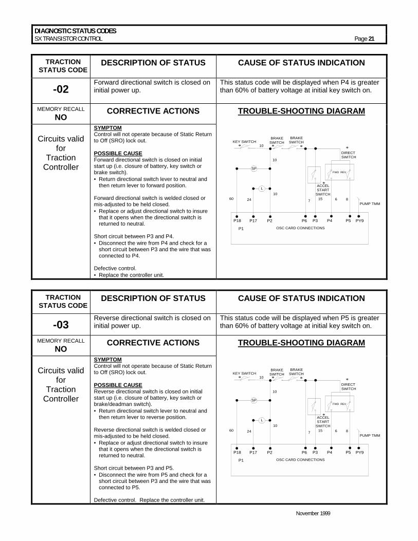
-02 Forward directional switch is closed on initial power up.
This status code will be displayed when P4 is greater than 60% of battery voltage at initial key switch on.
MEMORY RECALL NO CORRECTIVE ACTIONS TROUBLE-SHOOTING DIAGRAM
Circuits valid
for Traction
Controller
SYMPTOM Control will not operate because of Static Return to Off (SRO) lock out. POSSIBLE CAUSE Forward directional switch is closed on initial start up (i.e. closure of battery, key switch or brake switch). • =Return directional switch lever to neutral and
then return lever to forward position. Forward directional switch is welded closed or mis-adjusted to be held closed. • =Replace or adjust directional switch to insure
that it opens when the directional switch is returned to neutral.
Short circuit between P3 and P4. • =Disconnect the wire from P4 and check for a
short circuit between P3 and the wire that was connected to P4.
Defective control. • =Replace the controller unit.
FWD REV
OSC CARD CONNECTIONS
DIRECT SWITCH
P18 P6 P4 PY9P5P3
P1
15760
10
10
6 8
*
*ACCELSTART
SWITCH
BRAKESWITCH
BRAKESWITCH
PUMP TMM
* *
L
SP
P17 P2
2410
KEY SWITCH*
TRACTION
STATUS CODE DESCRIPTION OF STATUS CAUSE OF STATUS INDICATION
-03 Reverse directional switch is closed on initial power up.
This status code will be displayed when P5 is greater than 60% of battery voltage at initial key switch on.
MEMORY RECALL NO CORRECTIVE ACTIONS TROUBLE-SHOOTING DIAGRAM
Circuits valid
for Traction
Controller
SYMPTOM Control will not operate because of Static Return to Off (SRO) lock out. POSSIBLE CAUSE Reverse directional switch is closed on initial start up (i.e. closure of battery, key switch or brake/deadman switch). • =Return directional switch lever to neutral and
then return lever to reverse position. Reverse directional switch is welded closed or mis-adjusted to be held closed. • =Replace or adjust directional switch to insure
that it opens when the directional switch is returned to neutral.
Short circuit between P3 and P5. • =Disconnect the wire from P5 and check for a
short circuit between P3 and the wire that was connected to P5.
Defective control. Replace the controller unit.
FWD REV
OSC CARD CONNECTIONS
DIRECT SWITCH
P18 P6 P4 PY9P5P3
P1
15760
10
10
6 8
*
*ACCELSTART
SWITCH
BRAKESWITCH
BRAKESWITCH
PUMP TMM
* *
L
SP
P17 P2
2410
KEY SWITCH*

DIAGNOSTIC STATUS CODES SX TRANSISTOR CONTROL Page 22
November 1999
TRACTION
STATUS CODE DESCRIPTION OF STATUS CAUSE OF STATUS INDICATION
-05 Start switch fails to close. This status code will be displayed when P7 is less
than 2.5 volts and P3 is less than 60% of battery volts.
MEMORY RECALL NO CORRECTIVE ACTIONS TROUBLE-SHOOTING DIAGRAM
Circuits valid
for Traction
Controller
SYMPTOM Control will not operate. POSSIBLE CAUSE Defective brake switch circuit. • =Check brake switch to insure closure when
accelerator is depressed. • =Check for open circuit or loose connections in
wiring from brake switch to start switch and from P3 to start switch.
Defective accelerator switch. • =Check accelerator switch potentiometer for
proper operation and ohmic value.
FWD REV
OSC CARD CONNECTIONS
DIRECT SWITCH
P18 P6 P4 PY9P5P3
157
60
10
68
*
*ACCELSTART
SWITCH
PUMP TMML
SP
P17 P2
24 10
10
BRAKESWITCH
BRAKESWITCH
* *KEY SWITCH
*
ACCELSW.
*
P7
TRACTION
STATUS CODE DESCRIPTION OF STATUS CAUSE OF STATUS INDICATION
-06 Accelerator depressed with no direction selected.
This status code will be displayed when P4 and P5 are less than 60% of battery volts, and P7 is less than 2.5 volts.
MEMORY RECALL NO CORRECTIVE ACTIONS TROUBLE-SHOOTING DIAGRAM
Circuits valid
for Traction
Controller
SYMPTOM Control will not operate. POSSIBLE CAUSE Accelerator pedal is depressed before closing forward or reverse directional switch. • =Status code will disappear when directional
switch is closed or when accelerator pedal is released.
Defective directional switch • =Check forward or reverse switch to insure
closure when direction is selected. Open circuit between directional switch(es) and battery positive or between directional switch(es) and P4 or P5. • =Check all control wires and connections shown
in Trouble Shooting Diagram.
FWD REV
OSC CARD CONNECTIONS
DIRECT SWITCH
P18 P6 P4 PY9P5P3
157
60
10
68
*
*ACCELSTART
SWITCH
PUMP TMML
SP
P17 P2
24 10
10
BRAKESWITCH
BRAKESWITCH
* *KEY SWITCH
*
ACCELSW.
*
P7
DIAGNOSTIC STATUS CODES SX TRANSISTOR CONTROL Page 23
November 1999
TRACTION
STATUS CODE DESCRIPTION OF STATUS CAUSE OF STATUS INDICATION
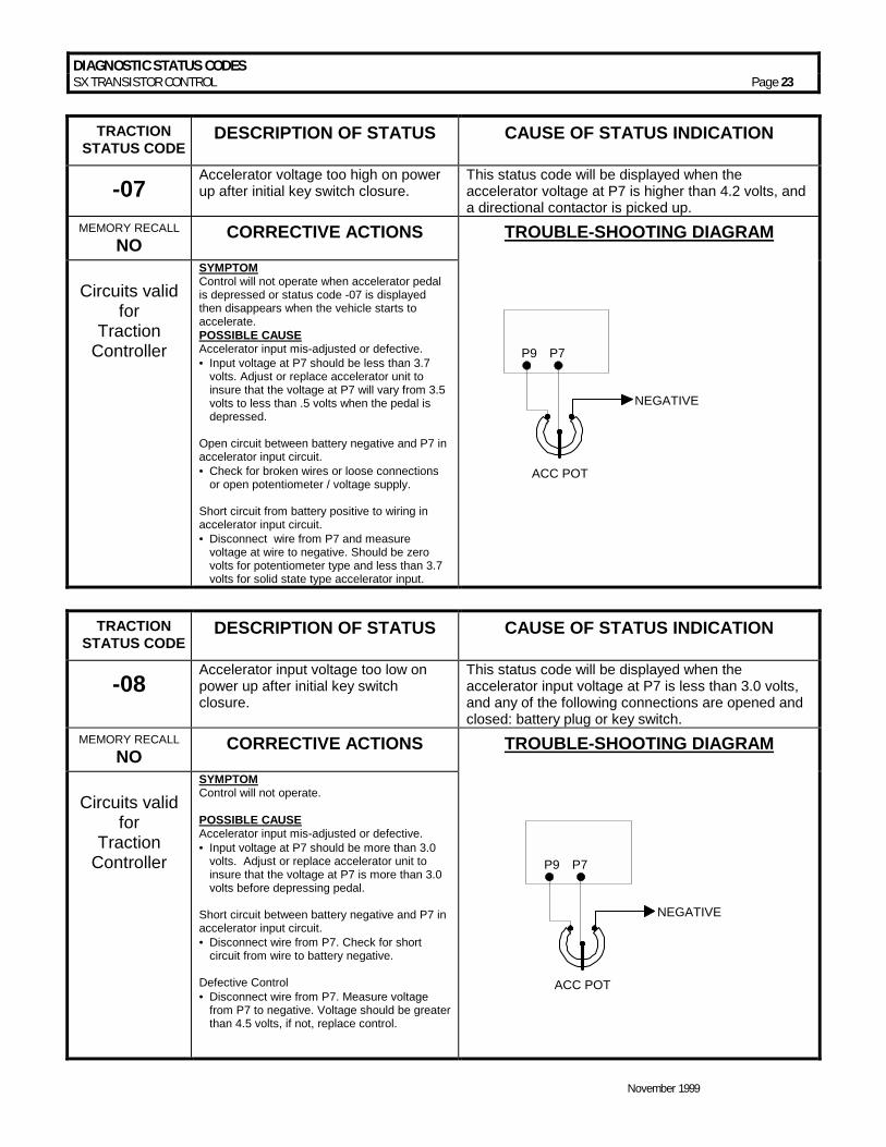
-07 Accelerator voltage too high on power up after initial key switch closure.
This status code will be displayed when the accelerator voltage at P7 is higher than 4.2 volts, and a directional contactor is picked up.
MEMORY RECALL NO CORRECTIVE ACTIONS TROUBLE-SHOOTING DIAGRAM
Circuits valid
for Traction
Controller
SYMPTOM Control will not operate when accelerator pedal is depressed or status code -07 is displayed then disappears when the vehicle starts to accelerate. POSSIBLE CAUSE Accelerator input mis-adjusted or defective. • = Input voltage at P7 should be less than 3.7
volts. Adjust or replace accelerator unit to insure that the voltage at P7 will vary from 3.5 volts to less than .5 volts when the pedal is depressed.
Open circuit between battery negative and P7 in accelerator input circuit. • =Check for broken wires or loose connections
or open potentiometer / voltage supply. Short circuit from battery positive to wiring in accelerator input circuit. • =Disconnect wire from P7 and measure
voltage at wire to negative. Should be zero volts for potentiometer type and less than 3.7 volts for solid state type accelerator input.
P9 P7
ACC POT
NEGATIVE
TRACTION
STATUS CODE DESCRIPTION OF STATUS CAUSE OF STATUS INDICATION
-08 Accelerator input voltage too low on power up after initial key switch closure.
This status code will be displayed when the accelerator input voltage at P7 is less than 3.0 volts, and any of the following connections are opened and closed: battery plug or key switch.
MEMORY RECALL NO CORRECTIVE ACTIONS TROUBLE-SHOOTING DIAGRAM
Circuits valid
for Traction
Controller
SYMPTOM Control will not operate. POSSIBLE CAUSE Accelerator input mis-adjusted or defective. • = Input voltage at P7 should be more than 3.0
volts. Adjust or replace accelerator unit to insure that the voltage at P7 is more than 3.0 volts before depressing pedal.
Short circuit between battery negative and P7 in accelerator input circuit. • =Disconnect wire from P7. Check for short
circuit from wire to battery negative. Defective Control • =Disconnect wire from P7. Measure voltage
from P7 to negative. Voltage should be greater than 4.5 volts, if not, replace control.
P9 P7
ACC POT
NEGATIVE

DIAGNOSTIC STATUS CODES SX TRANSISTOR CONTROL Page 24
November 1999
TRACTION
STATUS CODE DESCRIPTION OF STATUS CAUSE OF STATUS INDICATION
-09 Both the forward and reverse directional switches are closed at the same time.
This status code will be displayed when P4 and P5 are greater than 60% of battery volts at the same time.
MEMORY RECALL NO CORRECTIVE ACTIONS TROUBLE-SHOOTING DIAGRAM
Circuits valid
for Traction
Controller
SYMPTOM Control will not operate. POSSIBLE CAUSE Forward or reverse directional switch welded closed or mis-adjusted to be held closed. • =Replace or adjust directional switches to
insure that they open when directional switch is returned to neutral.
Short circuit between battery positive and P4 and/or P5. • =Disconnect wires from P4 and P5 and check
wire for short circuit to positive side of directional switch.
Defective Control • =Disconnect wires and measure voltage at P4
and P5. Voltage should be less than 60% of battery volts.
FWD REV
OSC CARD CONNECTIONS
DIRECT SWITCH
P18 P6 P4 PY9P5P3
157
60
10
68
*
*ACCELSTART
SWITCH
PUMP TMML
SP
P17 P2
24 10
10
BRAKESWITCH
BRAKESWITCH
* *KEY SWITCH
*
ACCELSW.
*
P7
TRACTION
STATUS CODE DESCRIPTION OF STATUS CAUSE OF STATUS INDICATION
-11 Start switch closed on power up after initial key switch closure.
This status code will be displayed when P3 is greater than 60% of battery voltage when the key switch is closed.
MEMORY RECALL NO CORRECTIVE ACTIONS TROUBLE-SHOOTING DIAGRAM
Circuits valid
for Traction
Controller
SYMPTOM Control will not operate. POSSIBLE CAUSE Start switch input mis-adjusted or defective. • = Input voltage at P3 should be less than 60% of
battery volts at key switch closing. Adjust or replace accelerator unit to insure that the voltage at P3 is less than 60% of battery volts before closing the start switch.
Short circuit between battery positive and P3 in start switch input circuit. • =Disconnect wire from P3. Check for short
circuit from this wire to battery positive. Defective control. • =Disconnect wire from P3. Measure voltage
from P3 to negative. Voltage should be zero, if not, replace control.
FWD REV
OSC CARD CONNECTIONS
DIRECT SWITCH
P18 P6 P4 PY9P5P3
157
60
10
68
*
*ACCELSTART
SWITCH
PUMP TMML
SP
P17 P2
24 10
10
BRAKESWITCH
BRAKESWITCH
* *KEY SWITCH
*
ACCELSW.
*
P7

DIAGNOSTIC STATUS CODES SX TRANSISTOR CONTROL Page 25
November 1999
TRACTION
STATUS CODE DESCRIPTION OF STATUS CAUSE OF STATUS INDICATION
-15 Battery voltage is too low or control card is mis-adjusted.
This status code will be displayed when the battery volts are less than 1.95 volts per cell at initial key switch on. See table below.
MEMORY RECALL NO CORRECTIVE ACTIONS TROUBLE-SHOOTING DIAGRAM
Circuits valid
for Traction
Controller
SYMPTOM Control will not operate. POSSIBLE CAUSE Discharged battery • =Check battery for proper open circuit voltage
as shown in “Trouble Shooting Diagram”, charge battery, if required.
Defective battery • =Check each battery cell for proper voltage
(greater than 1.95 volts at cell). Replace or repair battery.
Incorrect control card adjustment. • =Check Function 15 for proper adjustment for
battery being used. See Handset instruction sheet for details. Adjust to proper settings.
Check “minimum” battery volts at P1 and NEG.
NEG
+
-
FU5
P1
NOMINALBATTERYVOLTAGE
MINIMUMLIMIT VOLTSAT 1.95 VDCPER CELL
24
80
4872
3623.4
78.0
46.870.2
35.1
TRACTION
STATUS CODE DESCRIPTION OF STATUS CAUSE OF STATUS INDICATION
-16 Battery voltage is too high or control card is mis-adjusted.
This status code will be displayed when the battery volts are greater than 2.4 volts per cell at initial key switch on. See table below.
MEMORY RECALL NO CORRECTIVE ACTIONS TROUBLE-SHOOTING DIAGRAM
Circuits valid
for Traction
Controller
SYMPTOM Control will not operate. POSSIBLE CAUSE Incorrect control card adjustment Check Function 15 for proper adjustment for battery being used. See Handset instructions for details. Adjust to proper setting. Battery over charged or incorrect battery used. • =Check battery for proper open circuit voltage
per table at right. If voltage is excessive, check battery charger for proper output voltage.
Check “maximum” battery volts at P1 and NEG.
NEG
+
-
FU5
P1
NOMINALBATTERYVOLTAGE
MINIMUMLIMIT VOLTSAT 1.95 VDCPER CELL
24
80
4872
3623.4
78.0
46.870.2
35.1

DIAGNOSTIC STATUS CODES SX TRANSISTOR CONTROL Page 26
November 1999
TRACTION
STATUS CODE DESCRIPTION OF STATUS CAUSE OF STATUS INDICATION
-23 Motor field current is high on start up in the reverse direction.
This status code will be displayed when the current draw in the motor field is too high at start up in the reverse direction.
MEMORY RECALL NO CORRECTIVE ACTIONS TROUBLE-SHOOTING DIAGRAM
Circuits valid
for Traction
Controller
SYMPTOM Control will not operate. POSSIBLE CAUSE Defective control. • =Replace controller unit.
NO GRAPHIC FOR THIS STATUS CODE
TRACTION
STATUS CODE DESCRIPTION OF STATUS CAUSE OF STATUS INDICATION
-24 Motor field current is high on start up in the forward direction.
This status code will be displayed when the current draw in the motor field is too high at start up in the forward direction.
MEMORY RECALL NO CORRECTIVE ACTIONS TROUBLE-SHOOTING DIAGRAM
Circuits valid
for Traction
Controller
SYMPTOM Control will not operate. POSSIBLE CAUSE Defective control. • =Replace controller unit.
FWD REV
OSC CARD CONNECTIONS
DIRECT SWITCH
P18 P6 P4 PY9P5P3
157
60
10
68
*
*ACCELSTART
SWITCH
PUMP TMML
SP
P17 P2
24 10
10
BRAKESWITCH
BRAKESWITCH
* *KEY SWITCH
*
ACCELSW.
*
P7
DIAGNOSTIC STATUS CODES SX TRANSISTOR CONTROL Page 27
November 1999
TRACTION
STATUS CODE DESCRIPTION OF STATUS CAUSE OF STATUS INDICATION
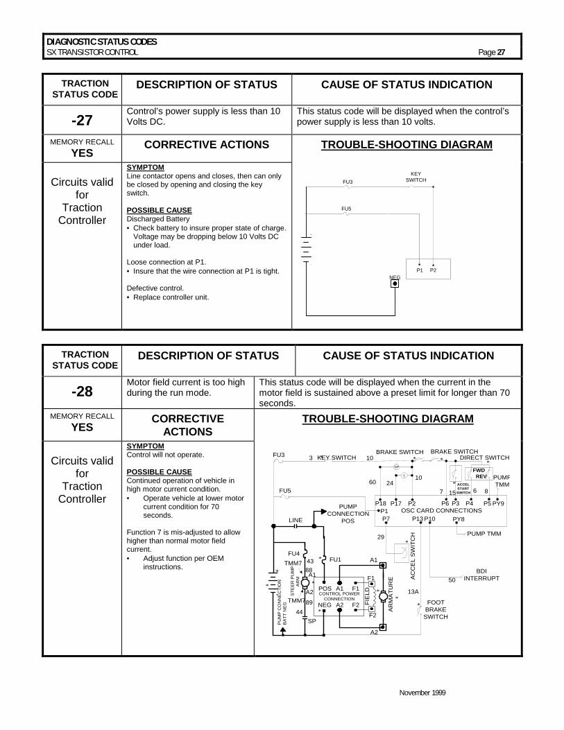
-27 Control’s power supply is less than 10 Volts DC.
This status code will be displayed when the control’s power supply is less than 10 volts.
MEMORY RECALL YES CORRECTIVE ACTIONS TROUBLE-SHOOTING DIAGRAM
Circuits valid
for Traction
Controller
SYMPTOM Line contactor opens and closes, then can only be closed by opening and closing the key switch. POSSIBLE CAUSE Discharged Battery • =Check battery to insure proper state of charge.
Voltage may be dropping below 10 Volts DC under load.
Loose connection at P1. • = Insure that the wire connection at P1 is tight. Defective control. • =Replace controller unit.
NEG
+
-
FU3KEY
SWITCH
P1 P2
FU5
TRACTION
STATUS CODE DESCRIPTION OF STATUS CAUSE OF STATUS INDICATION
-28 Motor field current is too high during the run mode.
This status code will be displayed when the current in the motor field is sustained above a preset limit for longer than 70 seconds.
MEMORY RECALL YES CORRECTIVE
ACTIONS TROUBLE-SHOOTING DIAGRAM
Circuits valid
for Traction
Controller
SYMPTOM Control will not operate. POSSIBLE CAUSE Continued operation of vehicle in high motor current condition. • = Operate vehicle at lower motor
current condition for 70 seconds.
Function 7 is mis-adjusted to allow higher than normal motor field current. • = Adjust function per OEM
instructions.
CONTROL POWERCONNECTION
POS A1 F1
NEG A2 F2 FIE
LD
AR
MA
TUR
E
FU1
FU5
PUMPCONNECTION
POS
KEY SWITCH
A2
A1
F1
F2
*
*
*
*
*
BDIINTERRUPT
13A
*29
50
FOOTBRAKE
SWITCH
*
PUMP TMM
FWD REV
OSC CARD CONNECTIONS
DIRECT SWITCH
P18 P6 P4 PY9P5P3
PY8P10P1P7 P13
15760
10
6 8
*
* ACCELSTARTSWITCH
BRAKE SWITCH BRAKE SWITCH
PUMPTMM
* *
L
SP
P17 P2
2410
A1
A2
SP
+
- STE
ER
PU
MP
AR
M
PU
MP
CO
NN
EC
TIO
NB
ATT
NE
G
LINE
FU4
FU3 3
TMM7
TMM78843
4489
**
AC
CE
L S
WIT
CH
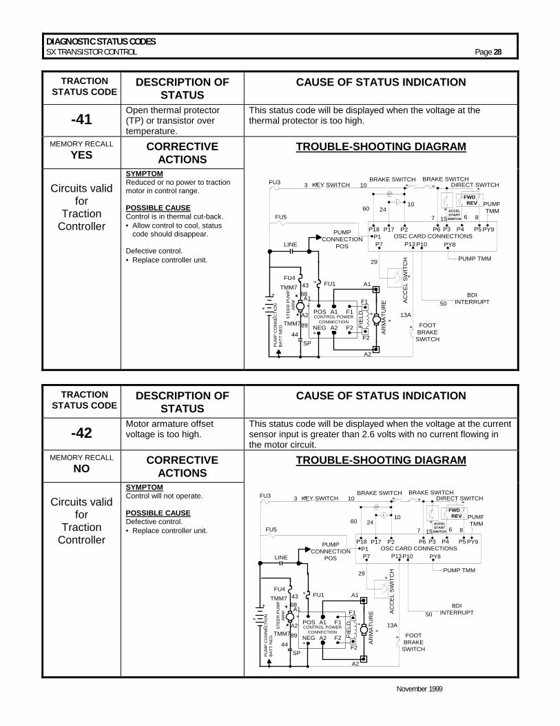
DIAGNOSTIC STATUS CODES SX TRANSISTOR CONTROL Page 28
November 1999
TRACTION STATUS CODE
DESCRIPTION OF STATUS
CAUSE OF STATUS INDICATION
-41 Open thermal protector (TP) or transistor over temperature.
This status code will be displayed when the voltage at the thermal protector is too high.
MEMORY RECALL YES CORRECTIVE
ACTIONS TROUBLE-SHOOTING DIAGRAM
Circuits valid
for Traction
Controller
SYMPTOM Reduced or no power to traction motor in control range. POSSIBLE CAUSE Control is in thermal cut-back. • =Allow control to cool, status
code should disappear. Defective control. • =Replace controller unit.
CONTROL POWERCONNECTION
POS A1 F1
NEG A2 F2 FIE
LD
AR
MA
TUR
E
FU1
FU5
PUMPCONNECTION
POS
KEY SWITCH
A2
A1
F1
F2
*
*
*
*
*
BDIINTERRUPT
13A
*
29
50
FOOTBRAKESWITCH
*
PUMP TMM
FWD REV
OSC CARD CONNECTIONS
DIRECT SWITCH
P18 P6 P4 PY9P5P3
PY8P10P1P7 P13
15760
10
6 8
*
* ACCELSTART
SWITCH
BRAKE SWITCH BRAKE SWITCH
PUMPTMM
* *
L
SP
P17 P2
2410
A1
A2
SP
+
- STE
ER
PU
MP
AR
M
PU
MP
CO
NN
EC
TIO
NB
ATT
NE
G
LINE
FU4
FU3 3
TMM7
TMM78843
4489
**
AC
CE
L S
WIT
CH
TRACTION STATUS CODE
DESCRIPTION OF STATUS
CAUSE OF STATUS INDICATION
-42 Motor armature offset voltage is too high.
This status code will be displayed when the voltage at the current sensor input is greater than 2.6 volts with no current flowing in the motor circuit.
MEMORY RECALL NO CORRECTIVE
ACTIONS TROUBLE-SHOOTING DIAGRAM
Circuits valid
for Traction
Controller
SYMPTOM Control will not operate. POSSIBLE CAUSE Defective control. • =Replace controller unit.
CONTROL POWERCONNECTION
POS A1 F1
NEG A2 F2 FIE
LD
AR
MA
TUR
E
FU1
FU5
PUMPCONNECTION
POS
KEY SWITCH
A2
A1
F1
F2
*
*
*
*
*
BDIINTERRUPT
13A
*29
50
FOOTBRAKE
SWITCH
*
PUMP TMM
FWD REV
OSC CARD CONNECTIONS
DIRECT SWITCH
P18 P6 P4 PY9P5P3
PY8P10P1P7 P13
15760
10
6 8
*
* ACCELSTART
SWITCH
BRAKE SWITCH BRAKE SWITCH
PUMPTMM
* *
L
SP
P17 P2
2410
A1
A2
SP
+
- STE
ER
PU
MP
AR
M
PU
MP
CO
NN
EC
TIO
NB
ATT
NE
G
LINE
FU4
FU3 3
TMM7
TMM78843
4489
**
AC
CE
L S
WIT
CH

DIAGNOSTIC STATUS CODES SX TRANSISTOR CONTROL Page 29
November 1999
TRACTION STATUS CODE
DESCRIPTION OF STATUS
CAUSE OF STATUS INDICATION
-43 Motor armature offset voltage is too low.
This status code will be displayed when the voltage at the current sensor input is less than 2.4 volts with no current flowing in the motor circuit.
MEMORY RECALL NO CORRECTIVE
ACTIONS TROUBLE-SHOOTING DIAGRAM
Circuits valid
for Traction
Controller
SYMPTOM Control will not operate. POSSIBLE CAUSE Defective control. • =Replace controller unit.
CONTROL POWERCONNECTION
POS A1 F1
NEG A2 F2 FIE
LD
AR
MA
TUR
E
FU1
FU5
PUMPCONNECTION
POS
KEY SWITCH
A2
A1
F1
F2
*
*
*
*
*
BDIINTERRUPT
13A
*29
50
FOOTBRAKE
SWITCH
*
PUMP TMM
FWD REV
OSC CARD CONNECTIONS
DIRECT SWITCH
P18 P6 P4 PY9P5P3
PY8P10P1P7 P13
15760
10
6 8
*
* ACCELSTART
SWITCH
BRAKE SWITCH BRAKE SWITCH
PUMPTMM
* *
L
SP
P17 P2
2410
A1
A2
SP
+
- STE
ER
PU
MP
AR
M
PU
MP
CO
NN
EC
TIO
NB
ATT
NE
G
LINE
FU4
FU3 3
TMM7
TMM78843
4489
**
AC
CE
L S
WIT
CH
TRACTION STATUS CODE
DESCRIPTION OF STATUS
CAUSE OF STATUS INDICATION
-44 Armature transistor did not turn off properly.
This status code will be displayed when, during control operation, the armature transistor fails to turn off. This will result in a PMT condition.
MEMORY RECALL YES CORRECTIVE
ACTIONS TROUBLE-SHOOTING DIAGRAM
Circuits valid
for Traction
Controller
SYMPTOM Line contactor opens and closes, then can only be closed by opening and closing the key switch. POSSIBLE CAUSE Defective control. • =Replace controller unit.
CONTROL POWERCONNECTION
POS A1 F1
NEG A2 F2 FIE
LD
AR
MA
TUR
E
FU1
FU5
PUMPCONNECTION
POS
KEY SWITCH
A2
A1
F1
F2
*
*
*
*
*
BDIINTERRUPT
13A
*29
50
FOOTBRAKE
SWITCH
*
PUMP TMM
FWD REV
OSC CARD CONNECTIONS
DIRECT SWITCH
P18 P6 P4 PY9P5P3
PY8P10P1P7 P13
15760
10
6 8
*
* ACCELSTART
SWITCH
BRAKE SWITCH BRAKE SWITCH
PUMPTMM
* *
L
SP
P17 P2
2410
A1
A2
SP
+
- STE
ER
PU
MP
AR
M
PU
MP
CO
NN
EC
TIO
NB
ATT
NE
G
LINE
FU4
FU3 3
TMM7
TMM78843
4489
**
AC
CE
L S
WIT
CH
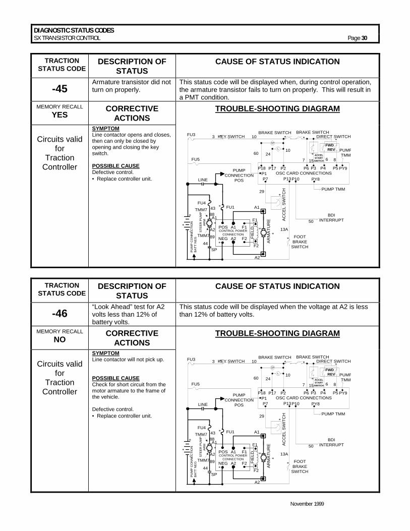
DIAGNOSTIC STATUS CODES SX TRANSISTOR CONTROL Page 30
November 1999
TRACTION
STATUS CODE DESCRIPTION OF
STATUS CAUSE OF STATUS INDICATION
-45 Armature transistor did not turn on properly.
This status code will be displayed when, during control operation, the armature transistor fails to turn on properly. This will result in a PMT condition.
MEMORY RECALL YES CORRECTIVE
ACTIONS TROUBLE-SHOOTING DIAGRAM
Circuits valid
for Traction
Controller
SYMPTOM Line contactor opens and closes, then can only be closed by opening and closing the key switch. POSSIBLE CAUSE Defective control. • =Replace controller unit.
CONTROL POWERCONNECTION
POS A1 F1
NEG A2 F2 FIE
LD
AR
MA
TUR
E
FU1
FU5
PUMPCONNECTION
POS
KEY SWITCH
A2
A1
F1
F2
*
*
*
*
*
BDIINTERRUPT
13A
*29
50
FOOTBRAKE
SWITCH
*
PUMP TMM
FWD REV
OSC CARD CONNECTIONS
DIRECT SWITCH
P18 P6 P4 PY9P5P3
PY8P10P1P7 P13
15760
10
6 8
*
* ACCELSTART
SWITCH
BRAKE SWITCH BRAKE SWITCH
PUMPTMM
* *
L
SP
P17 P2
2410
A1
A2
SP
+
- STE
ER
PU
MP
AR
M
PU
MP
CO
NN
EC
TIO
NB
ATT
NE
G
LINE
FU4
FU3 3
TMM7
TMM78843
4489
**
AC
CE
L S
WIT
CH
TRACTION STATUS CODE
DESCRIPTION OF STATUS
CAUSE OF STATUS INDICATION
-46 “Look Ahead” test for A2 volts less than 12% of battery volts.
This status code will be displayed when the voltage at A2 is less than 12% of battery volts.
MEMORY RECALL NO CORRECTIVE
ACTIONS TROUBLE-SHOOTING DIAGRAM
Circuits valid
for Traction
Controller
SYMPTOM Line contactor will not pick up. POSSIBLE CAUSE Check for short circuit from the motor armature to the frame of the vehicle. Defective control. • =Replace controller unit.
CONTROL POWERCONNECTION
POS A1 F1
NEG A2 F2 FIE
LD
AR
MA
TUR
E
FU1
FU5
PUMPCONNECTION
POS
KEY SWITCH
A2
A1
F1
F2
*
*
*
*
*
BDIINTERRUPT
13A
*29
50
FOOTBRAKE
SWITCH
*
PUMP TMM
FWD REV
OSC CARD CONNECTIONS
DIRECT SWITCH
P18 P6 P4 PY9P5P3
PY8P10P1P7 P13
15760
10
6 8
*
* ACCELSTART
SWITCH
BRAKE SWITCH BRAKE SWITCH
PUMPTMM
* *
L
SP
P17 P2
2410
A1
A2
SP
+
- STE
ER
PU
MP
AR
M
PU
MP
CO
NN
EC
TIO
NB
ATT
NE
G
LINE
FU4
FU3 3
TMM7
TMM78843
4489
**
AC
CE
L S
WIT
CH

DIAGNOSTIC STATUS CODES SX TRANSISTOR CONTROL Page 31
November 1999
TRACTION STATUS CODE
DESCRIPTION OF STATUS
CAUSE OF STATUS INDICATION
-49 Motor field current is too low during the run mode.
This status code will be displayed when the current draw in the motor field is too low during the run mode.
MEMORY RECALL NO CORRECTIVE
ACTIONS TROUBLE-SHOOTING DIAGRAM
Circuits valid
for Traction
Controller
SYMPTOM Control will not operate. POSSIBLE CAUSE Defective control. • =Replace controller unit.
CONTROL POWERCONNECTION
POS A1 F1
NEG A2 F2 FIE
LD
AR
MA
TUR
E
FU1
FU5
PUMPCONNECTION
POS
KEY SWITCH
A2
A1
F1
F2
*
*
*
*
*
BDIINTERRUPT
13A
*29
50
FOOTBRAKE
SWITCH
*
PUMP TMM
FWD REV
OSC CARD CONNECTIONS
DIRECT SWITCH
P18 P6 P4 PY9P5P3
PY8P10P1P7 P13
15760
10
6 8
*
* ACCELSTART
SWITCH
BRAKE SWITCH BRAKE SWITCH
PUMPTMM
* *
L
SP
P17 P2
2410
A1
A2
SP
+
- STE
ER
PU
MP
AR
M
PU
MP
CO
NN
EC
TIO
NB
ATT
NE
G
LINE
FU4
FU3 3
TMM7
TMM78843
4489
**
AC
CE
L S
WIT
CH
TRACTION STATUS CODE
DESCRIPTION OF STATUS
CAUSE OF STATUS INDICATION
-51 Capacitor volts are low before the line contactor closes.
This status code will be displayed during “key on” when the capacitor volts is less than 85% of battery volts at initial key switch on.
MEMORY RECALL NO CORRECTIVE ACTIONS TROUBLE-SHOOTING DIAGRAM
Circuits valid
for Traction
Controller
SYMPTOM Line contactor does not close when capacitor does not precharge. POSSIBLE CAUSE Defective control fuse. • =Check control fuse for open circuit.
Replace fuse, if necessary. Defective control. • =Replace controller unit.
CONTROL POWERCONNECTION
POS A1 F1
NEG A2 F2 FIE
LD
AR
MA
TUR
E
FU1
FU5
PUMPCONNECTION
POS
KEY SWITCH
A2
A1
F1
F2
*
*
*
*
*
BDIINTERRUPT
13A
*29
50
FOOTBRAKE
SWITCH
*
PUMP TMM
FWD REV
OSC CARD CONNECTIONS
DIRECT SWITCH
P18 P6 P4 PY9P5P3
PY8P10P1P7 P13
15760
10
6 8
*
* ACCELSTART
SWITCH
BRAKE SWITCH BRAKE SWITCH
PUMPTMM
* *
L
SP
P17 P2
2410
A1
A2
SP
+
- STE
ER
PU
MP
AR
M
PU
MP
CO
NN
EC
TIO
NB
ATT
NE
G
LINE
FU4
FU3 3
TMM7
TMM78843
4489
**
AC
CE
L S
WIT
CH
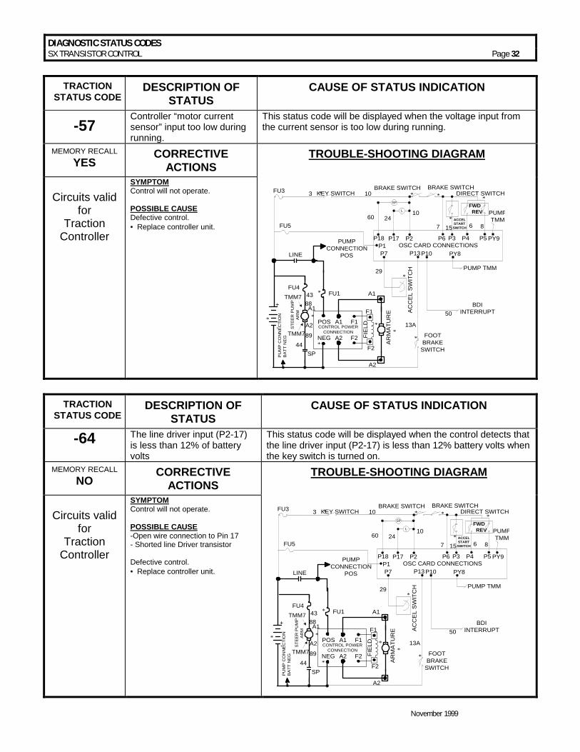
DIAGNOSTIC STATUS CODES SX TRANSISTOR CONTROL Page 32
November 1999
TRACTION
STATUS CODE DESCRIPTION OF
STATUS CAUSE OF STATUS INDICATION
-57 Controller “motor current sensor” input too low during running.
This status code will be displayed when the voltage input from the current sensor is too low during running.
MEMORY RECALL YES CORRECTIVE
ACTIONS TROUBLE-SHOOTING DIAGRAM
Circuits valid
for Traction
Controller
SYMPTOM Control will not operate. POSSIBLE CAUSE Defective control. • =Replace controller unit.
CONTROL POWERCONNECTION
POS A1 F1
NEG A2 F2 FIE
LD
AR
MA
TUR
E
FU1
FU5
PUMPCONNECTION
POS
KEY SWITCH
A2
A1
F1
F2
*
*
*
*
*
BDIINTERRUPT
13A
*29
50
FOOTBRAKE
SWITCH
*
PUMP TMM
FWD REV
OSC CARD CONNECTIONS
DIRECT SWITCH
P18 P6 P4 PY9P5P3
PY8P10P1P7 P13
15760
10
6 8
*
* ACCELSTART
SWITCH
BRAKE SWITCH BRAKE SWITCH
PUMPTMM
* *
L
SP
P17 P2
2410
A1
A2
SP
+
- STE
ER
PU
MP
AR
M
PU
MP
CO
NN
EC
TIO
NB
ATT
NE
G
LINE
FU4
FU3 3
TMM7
TMM78843
4489
**
AC
CE
L S
WIT
CH
TRACTION STATUS CODE
DESCRIPTION OF STATUS
CAUSE OF STATUS INDICATION
-64 The line driver input (P2-17) is less than 12% of battery volts
This status code will be displayed when the control detects that the line driver input (P2-17) is less than 12% battery volts when the key switch is turned on.
MEMORY RECALL NO CORRECTIVE
ACTIONS TROUBLE-SHOOTING DIAGRAM
Circuits valid
for Traction
Controller
SYMPTOM Control will not operate. POSSIBLE CAUSE -Open wire connection to Pin 17 - Shorted line Driver transistor Defective control. • =Replace controller unit.
CONTROL POWERCONNECTION
POS A1 F1
NEG A2 F2 FIE
LD
AR
MA
TUR
E
FU1
FU5
PUMPCONNECTION
POS
KEY SWITCH
A2
A1
F1
F2
*
*
*
*
*
BDIINTERRUPT
13A
*29
50
FOOTBRAKE
SWITCH
*
PUMP TMM
FWD REV
OSC CARD CONNECTIONS
DIRECT SWITCH
P18 P6 P4 PY9P5P3
PY8P10P1P7 P13
15760
10
6 8
*
* ACCELSTART
SWITCH
BRAKE SWITCH BRAKE SWITCH
PUMPTMM
* *
L
SP
P17 P2
2410
A1
A2
SP
+
- STE
ER
PU
MP
AR
M
PU
MP
CO
NN
EC
TIO
NB
ATT
NE
G
LINE
FU4
FU3 3
TMM7
TMM78843
4489
**
AC
CE
L S
WIT
CH

DIAGNOSTIC STATUS CODES SX TRANSISTOR CONTROL Page 33
November 1999
TRACTION STATUS CODE
DESCRIPTION OF STATUS
CAUSE OF STATUS INDICATION
-65 The line coil or steer pump coil current is too high during the run mode.
This status code will be displayed when the current limit in the line coil is exceeded during the run mode. The line contactor will drop out and the key switch will have to be recycled to reset the control.
MEMORY RECALL YES CORRECTIVE
ACTIONS TROUBLE-SHOOTING DIAGRAM
Circuits valid
for Traction
Controller
SYMPTOM Control will not operate. POSSIBLE CAUSE - Shorted line contactor coil - Short between wires connected to line coil (wires #10 and 24) If line coil resistance is correct: Defective control. • = Replace controller unit.
CONTROL POWERCONNECTION
POS A1 F1
NEG A2 F2 FIE
LD
AR
MA
TUR
E
FU1
FU5
PUMPCONNECTION
POS
KEY SWITCH
A2
A1
F1
F2
*
*
*
*
*
BDIINTERRUPT
13A
*29
50
FOOTBRAKE
SWITCH
*
PUMP TMM
FWD REV
OSC CARD CONNECTIONS
DIRECT SWITCH
P18 P6 P4 PY9P5P3
PY8P10P1P7 P13
15760
10
6 8
*
* ACCELSTART
SWITCH
BRAKE SWITCH BRAKE SWITCH
PUMPTMM
* *
L
SP
P17 P2
2410
A1
A2
SP
+
- STE
ER
PU
MP
AR
M
PU
MP
CO
NN
EC
TIO
NB
ATT
NE
G
LINE
FU4
FU3 3
TMM7
TMM78843
4489
**
AC
CE
L S
WIT
CH
TRACTION STATUS CODE
DESCRIPTION OF STATUS
CAUSE OF STATUS INDICATION
-66 The field current exceeds the current limit of the field transistor.
This status code will be displayed when the field transistor exceeds its specific current limit. The line contactor will drop out and the key switch will have to be recycled to restart the control.
MEMORY RECALL YES CORRECTIVE
ACTIONS TROUBLE-SHOOTING DIAGRAM
Circuits valid
for Traction
Controller
SYMPTOM Control will not operate • = Line contactor opens POSSIBLE CAUSE • =Shorted field F1 to F2 • =F1 or F2 terminals shorted to
battery positive (B+) • =F1 or F2 terminals shorted to
battery negative (B-)
CONTROL POWERCONNECTION
POS A1 F1
NEG A2 F2 FIE
LD
AR
MA
TUR
E
FU1
FU5
PUMPCONNECTION
POS
KEY SWITCH
A2
A1
F1
F2
*
*
*
*
*
BDIINTERRUPT
13A
*29
50
FOOTBRAKE
SWITCH
*
PUMP TMM
FWD REV
OSC CARD CONNECTIONS
DIRECT SWITCH
P18 P6 P4 PY9P5P3
PY8P10P1P7 P13
15760
10
6 8
*
* ACCELSTART
SWITCH
BRAKE SWITCH BRAKE SWITCH
PUMPTMM
* *
L
SP
P17 P2
2410
A1
A2
SP
+
- STE
ER
PU
MP
AR
M
PU
MP
CO
NN
EC
TIO
NB
ATT
NE
G
LINE
FU4
FU3 3
TMM7
TMM78843
4489
**
AC
CE
L S
WIT
CH

DIAGNOSTIC STATUS CODES SX TRANSISTOR CONTROL Page 34
November 1999
TRACTION STATUS CODE
DESCRIPTION OF STATUS
CAUSE OF STATUS INDICATION
-67 The armature current exceeds the armature transistor limit.
This status code will be displayed when the armature transistor exceeds its specific current limit. The control is reset by recycling the key switch.
MEMORY RECALL YES CORRECTIVE
ACTIONS TROUBLE-SHOOTING DIAGRAM
Circuits valid
for Traction
Controller
SYMPTOM Control will not operate. POSSIBLE CAUSE • = Shorted motor armature A1 to A2 • = Power cables may be shorted to
each other (Measure at control terminals)
• = A1 to A2 terminals may be shorted to battery positive or negative
CONTROL POWERCONNECTION
POS A1 F1
NEG A2 F2 FIE
LD
AR
MA
TUR
E
FU1
FU5
PUMPCONNECTION
POS
KEY SWITCH
A2
A1
F1
F2
*
*
*
*
*
BDIINTERRUPT
13A
*29
50
FOOTBRAKE
SWITCH
*
PUMP TMM
FWD REV
OSC CARD CONNECTIONS
DIRECT SWITCH
P18 P6 P4 PY9P5P3
PY8P10P1P7 P13
15760
10
6 8
*
* ACCELSTART
SWITCH
BRAKE SWITCH BRAKE SWITCH
PUMPTMM
* *
L
SP
P17 P2
2410
A1
A2
SP
+
- STE
ER
PU
MP
AR
M
PU
MP
CO
NN
EC
TIO
NB
ATT
NE
G
LINE
FU4
FU3 3
TMM7
TMM78843
4489
**
AC
CE
L S
WIT
CH
TRACTION STATUS CODE
DESCRIPTION OF STATUS
CAUSE OF STATUS INDICATION
-76 Capacitor (1C) voltage too high.
This status code will be displayed when the voltage on the capacitor goes above limit voltage* during the regenerative braking cycle.
MEMORY RECALL YES CORRECTIVE
ACTIONS TROUBLE-SHOOTING DIAGRAM
Circuits valid
for Traction
Controller
SYMPTOM Line contactor opens and closes, then opens and can only close by opening and closing the key switch. POSSIBLE CAUSE • =Unplugging the battery connector
during regenerative braking. • = Line contactor bouncing open
during regen. • =Main power fuse opening during
regen. • = Intermittent battery plug
connection. * Limit Voltage: Limit Batt. 50V 36V 70V 48V 96V 72/80V
CONTROL POWERCONNECTION
POS A1 F1
NEG A2 F2 FIE
LD
AR
MA
TUR
E
FU1
FU5
PUMPCONNECTION
POS
KEY SWITCH
A2
A1
F1
F2
*
*
*
*
*
BDIINTERRUPT
13A
*29
50
FOOTBRAKE
SWITCH
*
PUMP TMM
FWD REV
OSC CARD CONNECTIONS
DIRECT SWITCH
P18 P6 P4 PY9P5P3
PY8P10P1P7 P13
15760
10
6 8
*
* ACCELSTART
SWITCH
BRAKE SWITCH BRAKE SWITCH
PUMPTMM
* *
L
SP
P17 P2
2410
A1
A2
SP
+
- STE
ER
PU
MP
AR
M
PU
MP
CO
NN
EC
TIO
NB
ATT
NE
G
LINE
FU4
FU3 3
TMM7
TMM78843
4489
**
AC
CE
L S
WIT
CH

DIAGNOSTIC STATUS CODES SX TRANSISTOR CONTROL Page 35
November 1999
TRACTION STATUS CODE
DESCRIPTION OF STATUS
CAUSE OF STATUS INDICATION
-77 Motor current is detected during regenerative braking.
This status code will be displayed when motoring current is detected during the regenerative braking cycle.
MEMORY RECALL YES CORRECTIVE ACTIONS TROUBLE-SHOOTING DIAGRAM
Circuits valid
for Traction
Controller
SYMPTOM Line contactor opens and closes, then opens and can only close by opening and closing the key switch. POSSIBLE CAUSE Defective control. • =Replace controller unit
CONTROL POWERCONNECTION
POS A1 F1
NEG A2 F2 FIE
LD
AR
MA
TUR
E
FU1
FU5
PUMPCONNECTION
POS
KEY SWITCH
A2
A1
F1
F2
*
*
*
*
*
BDIINTERRUPT
13A
*29
50
FOOTBRAKE
SWITCH
*
PUMP TMM
FWD REV
OSC CARD CONNECTIONS
DIRECT SWITCH
P18 P6 P4 PY9P5P3
PY8P10P1P7 P13
15760
10
6 8
*
* ACCELSTART
SWITCH
BRAKE SWITCH BRAKE SWITCH
PUMPTMM
* *
L
SP
P17 P2
2410
A1
A2
SP
+
- STE
ER
PU
MP
AR
M
PU
MP
CO
NN
EC
TIO
NB
ATT
NE
G
LINE
FU4
FU3 3
TMM7
TMM78843
4489
**
AC
CE
L S
WIT
CH
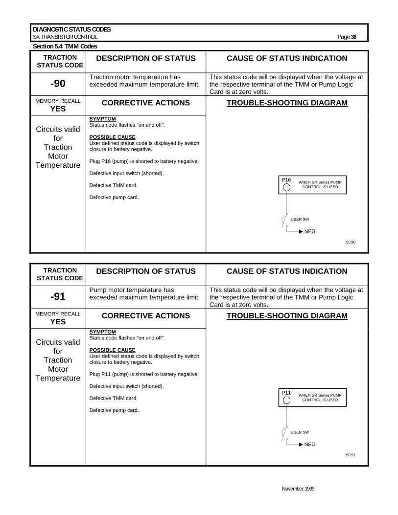
DIAGNOSTIC STATUS CODES SX TRANSISTOR CONTROL Page 36
November 1999
Section 5.4 TMM Codes
TRACTION STATUS CODE
DESCRIPTION OF STATUS CAUSE OF STATUS INDICATION
-90 Traction motor temperature has exceeded maximum temperature limit.
This status code will be displayed when the voltage at the respective terminal of the TMM or Pump Logic Card is at zero volts.
MEMORY RECALL YES CORRECTIVE ACTIONS TROUBLE-SHOOTING DIAGRAM
Circuits valid
for Traction Motor
Temperature
SYMPTOM Status code flashes “on and off”. POSSIBLE CAUSE User defined status code is displayed by switch closure to battery negative. Plug P16 (pump) is shorted to battery negative. Defective input switch (shorted). Defective TMM card. Defective pump card.
P16
SC90
NEG
USER SW
WHEN SR Series PUMPCONTROL IS USED
TRACTION STATUS CODE
DESCRIPTION OF STATUS CAUSE OF STATUS INDICATION
-91 Pump motor temperature has exceeded maximum temperature limit.
This status code will be displayed when the voltage at the respective terminal of the TMM or Pump Logic Card is at zero volts.
MEMORY RECALL YES CORRECTIVE ACTIONS TROUBLE-SHOOTING DIAGRAM
Circuits valid
for Traction Motor
Temperature
SYMPTOM Status code flashes “on and off”. POSSIBLE CAUSE User defined status code is displayed by switch closure to battery negative. Plug P11 (pump) is shorted to battery negative. Defective input switch (shorted). Defective TMM card. Defective pump card.
P11
SC91
NEG
USER SW
WHEN SR Series PUMPCONTROL IS USED

DIAGNOSTIC STATUS CODES SX TRANSISTOR CONTROL Page 37
November 1999
TRACTION
STATUS CODE DESCRIPTION OF STATUS CAUSE OF STATUS INDICATION
-93 Steering pump motor brush wear indicator has detected worn brush.
This status code will be displayed when the voltage at the respective terminal of the TMM or Pump Logic Card is at battery volts.
MEMORY RECALL YES CORRECTIVE ACTIONS TROUBLE-SHOOTING DIAGRAM
Circuits valid
for Steer Pump Motor
Brush Wear Indicator
SYMPTOM Status code flashes “on and off”. POSSIBLE CAUSE User defined status code is displayed by motor brush sensor closure to battery positive. Plug P3 (pump) is shorted to positive. Defective input switch (shorted). Defective TMM card. Defective pump card.
SC93
POS
P3
USER SW
WHEN SR Series PUMPCONTROL IS USED
TRACTION STATUS CODE
DESCRIPTION OF STATUS CAUSE OF STATUS INDICATION
-93 Steering pump motor brush wear indicator has detected worn brush.
This status code will be displayed when the voltage at the respective terminal of the TMM or Pump Logic Card is at battery volts.
MEMORY RECALL YES CORRECTIVE ACTIONS TROUBLE-SHOOTING DIAGRAM
Circuits valid
for Steering Pump Motor
Brush Wear Indicator
SYMPTOM Status code flashes “on and off”. POSSIBLE CAUSE User defined status code is displayed by motor brush sensor closure to battery positive. Plug P4 (pump) is shorted to positive. Defective input switch (shorted). Defective TMM card. Defective pump card.
SC93A
POS
P4
USER SW
WHEN SR Series PUMPCONTROL IS USED

DIAGNOSTIC STATUS CODES SX TRANSISTOR CONTROL Page 38
November 1999
TRACTION
STATUS CODE DESCRIPTION OF STATUS CAUSE OF STATUS INDICATION
-94 Traction motor brush wear indicator has detected worn brush.
This status code will be displayed when the voltage at the respective terminal of the TMM or Pump Logic Card is at battery volts.
MEMORY RECALL YES CORRECTIVE ACTIONS TROUBLE-SHOOTING DIAGRAM
Circuits valid
for Traction Motor
Brush Wear Indicator
SYMPTOM Status code flashes “on and off”. POSSIBLE CAUSE User defined status code is displayed by motor brush sensor closure to battery positive. Plug P5 (pump) is shorted to positive. Defective input switch (shorted). Defective TMM card. Defective pump card.
SC94
POS
P5
USER SW
WHEN SR Series PUMPCONTROL IS USED
TRACTION STATUS CODE
DESCRIPTION OF STATUS CAUSE OF STATUS INDICATION
-94 Traction motor brush wear indicator had detected worn brush.
This status code will be displayed when the voltage at the respective terminal of the TMM or Pump Logic Card is at zero volts.
MEMORY RECALL YES CORRECTIVE ACTIONS TROUBLE-SHOOTING DIAGRAM
Circuits valid
for Traction Motor
Brush Wear
SYMPTOM Status code flashes “on and off”. POSSIBLE CAUSE User defined status code is displayed by motor brush sensor closure to battery positive. . Plug P6 (pump) is shorted to positive. Defective input switch (shorted). Defective TMM card. Defective pump card.
SC94A
POS
P6
USER SW
WHEN SR Series PUMPCONTROL IS USED
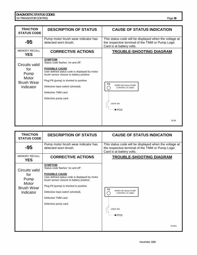
DIAGNOSTIC STATUS CODES SX TRANSISTOR CONTROL Page 39
November 1999
TRACTION
STATUS CODE DESCRIPTION OF STATUS CAUSE OF STATUS INDICATION
-95 Pump motor brush wear indicator has detected worn brush.
This status code will be displayed when the voltage at the respective terminal of the TMM or Pump Logic Card is at battery volts.
MEMORY RECALL YES CORRECTIVE ACTIONS TROUBLE-SHOOTING DIAGRAM
Circuits valid
for Pump Motor
Brush Wear Indicator
SYMPTOM Status code flashes “on and off”. POSSIBLE CAUSE User defined status code is displayed by motor brush sensor closure to battery positive. Plug P8 (pump) is shorted to positive. Defective input switch (shorted). Defective TMM card. Defective pump card.
SC95
POS
P8
USER SW
WHEN SR Series PUMPCONTROL IS USED
TRACTION STATUS CODE
DESCRIPTION OF STATUS CAUSE OF STATUS INDICATION
-95 Pump motor brush wear indicator has detected worn brush.
This status code will be displayed when the voltage at the respective terminal of the TMM or Pump Logic Card is at battery volts.
MEMORY RECALL YES CORRECTIVE ACTIONS TROUBLE-SHOOTING DIAGRAM
Circuits valid
for Pump Motor
Brush Wear Indicator
SYMPTOM Status code flashes “on and off”. POSSIBLE CAUSE User defined status code is displayed by motor brush sensor closure to battery positive. Plug P9 (pump) is shorted to positive. Defective input switch (shorted). Defective TMM card. Defective pump card.
SC95A
POS
P9
USER SW
WHEN SR Series PUMPCONTROL IS USED

DIAGNOSTIC STATUS CODES SX TRANSISTOR CONTROL Page 40
November 1999
TRACTION
STATUS CODE DESCRIPTION OF STATUS CAUSE OF STATUS INDICATION
-99 Maintenance alert and speed limit. This status code will be displayed when the “normal”
hour meter exceeds the “maintenance alert hours” setting for the vehicle.
MEMORY RECALL YES CORRECTIVE ACTIONS TROUBLE-SHOOTING DIAGRAM
Circuits valid
for Traction
Controller
SYMPTOM Status code is displayed for 4 seconds when the key switch is first turned on, and/or the vehicle may run at a reduced speed. CUSTOMER SELECTED SETTING WITH THE HANDSET: User defined status code is displayed when the normal hour meter reading exceeds the programmed “maintenance alert hours” setting selected by the user • =Maintenance Code Hour Meter, Functions 19
and 20, are programmed with the Handset and command the display of status code -99.
• = If desired, Maintenance Code Speed Limit, Function 13, can be programmed with the Handset.
User should perform the desired maintenance function. Re-set maintenance alert hour meter after maintenance is performed.
NO DIAGRAM
USER SHOULD PERFORM THE DESIRED MAINTENANCE FUNCTION

DIAGNOSTIC STATUS CODES TRANSISTOR PUMP CONTROL Page 41
November 1999
Section 4.6 Pump Control Codes
PUMP STATUS CODE
DESCRIPTION OF STATUS CAUSE OF STATUS INDICATION
-101 “SPEED 1” switch closed with the key turned off.
This status code will be displayed when the “SPEED 1” switch closes while the key switch is turned off.
MEMORY RECALL NO CORRECTIVE ACTIONS TROUBLE-SHOOTING DIAGRAM
Circuits valid
for Pump
Controller
SYMPTOM Control will not operate. POSSIBLE CAUSE “SPEED 1” switch is closed or shorted to battery negative. • = Verify connections at P12 and Battery
negative. Replace switch, if necessary.
12192021
51
**
SP
EE
D 2
SP
EE
D 1
5253
*
SP
EE
D 3
*
SP
EE
D 4
7
AC
CE
LER
ATO
RS
WIT
CH
*BATTNEG 13C 13C13C13C
SX
-2C
ON
TRO
LP
LUG
PL2
PUMP STATUS CODE
DESCRIPTION OF STATUS CAUSE OF STATUS INDICATION
-102 “SPEED 2” switch closed with the key turned off.
This status code will be displayed when the “SPEED 2” switch closes while the key switch is turned off.
MEMORY RECALL NO CORRECTIVE ACTIONS TROUBLE-SHOOTING DIAGRAM
Circuits valid
for Pump
Controller
SYMPTOM Control will not operate. POSSIBLE CAUSE “SPEED 2” switch is closed or shorted to battery negative. • = Verify connections at P19 and Battery
negative. Replace switch, if necessary.
12192021
51
**
SP
EE
D 2
SP
EE
D 1
5253
*
SP
EE
D 3
*
SP
EE
D 4
7A
CC
ELE
RA
TOR
SW
ITC
H
*BATTNEG 13C 13C13C13C
SX
-2C
ON
TRO
LP
LUG
PL2

DIAGNOSTIC STATUS CODES TRANSISTOR PUMP CONTROL Page 42
November 1999
PUMP
STATUS CODE DESCRIPTION OF STATUS CAUSE OF STATUS INDICATION
-103 “SPEED 3” switch closed with the key turned off.
This status code will be displayed when the “SPEED 3” switch closes while the key switch is turned off.
MEMORY RECALL NO CORRECTIVE ACTIONS TROUBLE-SHOOTING DIAGRAM
Circuits valid
for Pump
Controller
SYMPTOM Control will not operate. POSSIBLE CAUSE “SPEED 3” switch is closed or shorted to battery negative. • = Verify connections at P20 and Battery
negative. Replace switch, if necessary.
12192021
51
**
SP
EE
D 2
SP
EE
D 1
5253
*
SP
EE
D 3
*
SP
EE
D 4
7
AC
CE
LER
ATO
RS
WIT
CH
*BATTNEG 13C 13C13C13C
SX
-2C
ON
TRO
LP
LUG
PL2
PUMP
STATUS CODE DESCRIPTION OF STATUS CAUSE OF STATUS INDICATION
-104 “SPEED 4” switch closed with the key turned off.
This status code will be displayed when the “SPEED 4” switch closes while the key switch is turned off.
MEMORY RECALL NO CORRECTIVE ACTIONS TROUBLE-SHOOTING DIAGRAM
Circuits valid
for Pump
Controller
SYMPTOM Control will not operate. POSSIBLE CAUSE “SPEED 4” switch is closed or shorted to battery negative. • = Verify connections at P21 and Battery
negative. Replace switch, if necessary.
12192021
51
**
SP
EE
D 2
SP
EE
D 1
5253
*
SP
EE
D 3
*
SP
EE
D 4
7A
CC
ELE
RA
TOR
SW
ITC
H
*BATTNEG 13C 13C13C13C
SX
-2C
ON
TRO
LP
LUG
PL2
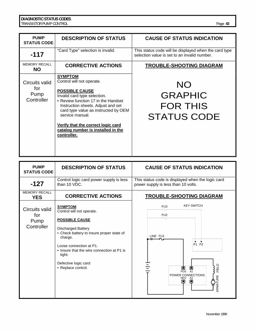
DIAGNOSTIC STATUS CODES TRANSISTOR PUMP CONTROL Page 43
November 1999
PUMP
STATUS CODE DESCRIPTION OF STATUS CAUSE OF STATUS INDICATION
-117 “Card Type” selection is invalid. This status code will be displayed when the card type
selection value is set to an invalid number.
MEMORY RECALL NO CORRECTIVE ACTIONS TROUBLE-SHOOTING DIAGRAM
Circuits valid
for Pump
Controller
SYMPTOM Control will not operate. POSSIBLE CAUSE Invalid card type selection. • =Review function 17 in the Handset
Instruction sheets. Adjust and set card type value as instructed by OEM service manual.
Verify that the correct logic card catalog number is installed in the controller.
NOGRAPHICFOR THIS
STATUS CODE
PUMP STATUS CODE
DESCRIPTION OF STATUS CAUSE OF STATUS INDICATION
-127 Control logic card power supply is less than 10 VDC.
This status code is displayed when the logic card power supply is less than 10 volts.
MEMORY RECALL YES CORRECTIVE ACTIONS TROUBLE-SHOOTING DIAGRAM
Circuits valid
for Pump
Controller
SYMPTOM Control will not operate. POSSIBLE CAUSE Discharged Battery • =Check battery to insure proper state of
charge. Loose connection at P1. • = Insure that the wire connection at P1 is
tight. Defective logic card • =Replace control.
FU3 KEY SWITCH
P1 P2
FU2
POWER CONNECTIONSPOS A1
NEG A2
FIEL
DAR
MAT
UR
E
+
-
FU1LINE

DIAGNOSTIC STATUS CODES TRANSISTOR PUMP CONTROL Page 44
November 1999
PUMP STATUS CODE
DESCRIPTION OF STATUS CAUSE OF STATUS INDICATION
-128 Armature current is too high during the lift mode.
Status code displayed when the current in the armature circuit is sustained above 400A for 70 sec.
MEMORY RECALL YES CORRECTIVE ACTIONS TROUBLE-SHOOTING DIAGRAM
Circuits valid
for Pump
Controller
SYMPTOM Control will not operate. POSSIBLE CAUSE Continued operation of vehicle in high motor current condition. •=Operate vehicle at lower motor current
condition for 70 seconds.
FU3 KEY SWITCH
P1 P2
FU2
POWER CONNECTIONSPOS A1
NEG A2
FIEL
DAR
MAT
UR
E
+
-
FU1LINE
PUMP STATUS CODE
DESCRIPTION OF STATUS
CAUSE OF STATUS INDICATION
-141 Open thermal protector (TP1) or transistor is over temperature.
This status code is displayed when the voltage at the thermal protector is greater than 0.8 volts.
MEMORY RECALL NO CORRECTIVE ACTIONS TROUBLE-SHOOTING DIAGRAM
Circuits valid
for Pump
Controller
SYMPTOM Reduced or no power to pump motor in control range. POSSIBLE CAUSE Control is in thermal cut-back. • =Allow control to cool, status code
should disappear.
13C 13C
13C
*
*SP
EE
D 2
SP
EE
D 1
13C
*
SP
EE
D 3
13C
*
SP
EE
D 4
ACC
ELER
ATO
RSW
ITC
H
*
ARM
ATU
RE
*
FIE
LD
PUMP CONTROLPOWER
CONNECTION
P A1
A2N
A1
A2
*
A2
A1
N
BA
TT (-
)
SX
-2C
ON
TRO
L PL
UG
PL2
21
10
12
19
20
21
50
51
TOTRACTIONPL2-10
52
53
7
FU2P
5A
10
12-1
KEY SW.
FU6
LIN
EC
ON
TAC
TOR
STATUS CODE 93 INPUTSTATUS CODE 93 INPUTSTATUS CODE 94 INPUTSTATUS CODE 94 INPUTSTATUS CODE 95 INPUTSTATUS CODE 95 INPUTSTATUS CODE 92 INPUTSTATUS CODE 90 INPUTSTATUS CODE 91 INPUTBRUSH WEAR OUTPUTOVER TEMP OUTPUT
345689
1516111314
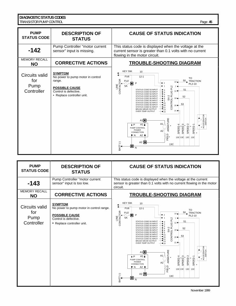
DIAGNOSTIC STATUS CODES TRANSISTOR PUMP CONTROL Page 45
November 1999
PUMP STATUS CODE
DESCRIPTION OF STATUS
CAUSE OF STATUS INDICATION
-142 Pump Controller “motor current sensor” input is missing.
This status code is displayed when the voltage at the current sensor is greater than 0.1 volts with no current flowing in the motor circuit.
MEMORY RECALL NO CORRECTIVE ACTIONS TROUBLE-SHOOTING DIAGRAM
Circuits valid
for Pump
Controller
SYMPTOM No power to pump motor in control range. POSSIBLE CAUSE Control is defective. • =Replace controller unit.
13C 13C
13C
*
*SPEE
D 2
SPEE
D 1
13C
*
SPEE
D 3
13C
*
SPEE
D 4
AC
CE
LER
ATO
RS
WIT
CH
*
ARM
ATU
RE
*
FIEL
D
PUMP CONTROLPOWER
CONNECTION
P A1
A2N
A1
A2
*
A2
A1
N
BATT
(-)
SX-2
CO
NTR
OL
PLU
G P
L2
21
10
12
19
20
21
50
51
TOTRACTIONPL2-10
52
53
7
FU2P
5A
10
12-1
KEY SW.
FU6
LIN
EC
ON
TAC
TOR
STATUS CODE 93 INPUTSTATUS CODE 93 INPUTSTATUS CODE 94 INPUTSTATUS CODE 94 INPUTSTATUS CODE 95 INPUTSTATUS CODE 95 INPUTSTATUS CODE 92 INPUTSTATUS CODE 90 INPUTSTATUS CODE 91 INPUTBRUSH WEAR OUTPUTOVER TEMP OUTPUT
345689
1516111314
PUMP STATUS CODE
DESCRIPTION OF STATUS
CAUSE OF STATUS INDICATION
-143 Pump Controller “motor current sensor” input is too low.
This status code is displayed when the voltage at the current sensor is greater than 0.1 volts with no current flowing in the motor circuit.
MEMORY RECALL NO CORRECTIVE ACTIONS TROUBLE-SHOOTING DIAGRAM
Circuits valid
for Pump
Controller
SYMPTOM No power to pump motor in control range. POSSIBLE CAUSE Control is defective. • =Replace controller unit.
13C 13C
13C
*
*SPEE
D 2
SPEE
D 1
13C
*
SPEE
D 3
13C
*
SPEE
D 4
AC
CE
LER
ATO
RS
WIT
CH
*
ARM
ATU
RE
*
FIEL
D
PUMP CONTROLPOWER
CONNECTION
P A1
A2N
A1
A2
*
A2
A1
N
BATT
(-)
SX-2
CO
NTR
OL
PLU
G P
L2
21
10
12
19
20
21
50
51
TOTRACTIONPL2-10
52
53
7
FU2P
5A
10
12-1
KEY SW.
FU6
LIN
EC
ON
TAC
TOR
STATUS CODE 93 INPUTSTATUS CODE 93 INPUTSTATUS CODE 94 INPUTSTATUS CODE 94 INPUTSTATUS CODE 95 INPUTSTATUS CODE 95 INPUTSTATUS CODE 92 INPUTSTATUS CODE 90 INPUTSTATUS CODE 91 INPUTBRUSH WEAR OUTPUTOVER TEMP OUTPUT
345689
1516111314

DIAGNOSTIC STATUS CODES TRANSISTOR PUMP CONTROL Page 46
November 1999
PUMP STATUS CODE
DESCRIPTION OF STATUS CAUSE OF STATUS INDICATION
-144 Power Transistor (Q1) did not turn off properly.
This status code is displayed when, during pump control operation, the transistor fails to turn off. This will result in a PMT condition.
MEMORY RECALL YES CORRECTIVE ACTIONS TROUBLE-SHOOTING DIAGRAM
Circuits valid
for Pump
Controller
SYMPTOM With no pump contactor, control may run continuously. POSSIBLE CAUSE Control is defective. • =Replace controller unit.
13C 13C
13C
*
*SP
EE
D 2
SP
EE
D 1
13C
*
SP
EE
D 3
13C
*
SP
EE
D 4
ACC
ELER
ATO
RSW
ITC
H
*
ARM
ATU
RE
*
FIE
LD
PUMP CONTROLPOWER
CONNECTION
P A1
A2N
A1
A2
*
A2
A1
N
BA
TT (-
)
SX
-2C
ON
TRO
L PL
UG
PL2
21
10
12
19
20
21
50
51
TOTRACTIONPL2-10
52
53
7
FU2P
5A
10
12-1
KEY SW.
FU6
LIN
EC
ON
TAC
TOR
STATUS CODE 93 INPUTSTATUS CODE 93 INPUTSTATUS CODE 94 INPUTSTATUS CODE 94 INPUTSTATUS CODE 95 INPUTSTATUS CODE 95 INPUTSTATUS CODE 92 INPUTSTATUS CODE 90 INPUTSTATUS CODE 91 INPUTBRUSH WEAR OUTPUTOVER TEMP OUTPUT
345689
1516111314
PUMP STATUS CODE
DESCRIPTION OF STATUS CAUSE OF STATUS INDICATION
-145 Power Transistor (Q1) did not turn on properly.
This status code is displayed when during pump control operation, the transistor fails to turn on.
MEMORY RECALL YES CORRECTIVE ACTIONS TROUBLE-SHOOTING DIAGRAM
Circuits valid
for Pump
Controller
SYMPTOM With no pump contactor, the control may run continuously. POSSIBLE CAUSE Control is defective. • =Replace controller unit.
13C 13C
13C
*
*SPEE
D 2
SPEE
D 1
13C
*
SPEE
D 3
13C
*
SPEE
D 4
AC
CE
LER
ATO
RS
WIT
CH
*
ARM
ATU
RE
*
FIEL
D
PUMP CONTROLPOWER
CONNECTION
P A1
A2N
A1
A2
*
A2
A1
N
BATT
(-)
SX-2
CO
NTR
OL
PLU
G P
L2
21
10
12
19
20
21
50
51
TOTRACTIONPL2-10
52
53
7
FU2P
5A
10
12-1
KEY SW.
FU6
LIN
EC
ON
TAC
TOR
STATUS CODE 93 INPUTSTATUS CODE 93 INPUTSTATUS CODE 94 INPUTSTATUS CODE 94 INPUTSTATUS CODE 95 INPUTSTATUS CODE 95 INPUTSTATUS CODE 92 INPUTSTATUS CODE 90 INPUTSTATUS CODE 91 INPUTBRUSH WEAR OUTPUTOVER TEMP OUTPUT
345689
1516111314

DIAGNOSTIC STATUS CODES TRANSISTOR PUMP CONTROL Page 47
November 1999
PUMP STATUS CODE
DESCRIPTION OF STATUS CAUSE OF STATUS INDICATION
-146 “Look Ahead” test for T2 volts less than 12% of battery volts.
This status code will be displayed when the voltage at T2 is less than 12% of battery volts.
MEMORY RECALL YES CORRECTIVE ACTIONS TROUBLE-SHOOTING DIAGRAM
Circuits valid
for Pump
Controller
SYMPTOM Pump control will not operate. POSSIBLE CAUSE Check for short circuit from the motor armature to the frame of the vehicle. Control is defective. • =Replace controller unit.
13C 13C
13C
*
*SPEE
D 2
SPEE
D 1
13C
*
SPEE
D 3
13C
*
SPEE
D 4
ACC
ELER
ATO
RSW
ITC
H
*
ARM
ATU
RE
*
FIEL
D
PUMP CONTROLPOWER
CONNECTION
P A1
A2N
A1
A2
*
A2
A1
N
BATT
(-)
SX-2
CO
NTR
OL
PLU
G P
L2
21
10
12
19
20
21
50
51
TOTRACTIONPL2-10
52
53
7
FU2P
5A
10
12-1
KEY SW.
FU6
LIN
EC
ON
TAC
TOR
STATUS CODE 93 INPUTSTATUS CODE 93 INPUTSTATUS CODE 94 INPUTSTATUS CODE 94 INPUTSTATUS CODE 95 INPUTSTATUS CODE 95 INPUTSTATUS CODE 92 INPUTSTATUS CODE 90 INPUTSTATUS CODE 91 INPUTBRUSH WEAR OUTPUTOVER TEMP OUTPUT
345689
1516111314
PUMP STATUS CODE
DESCRIPTION OF STATUS
CAUSE OF STATUS INDICATION
-150 Capacitor volts are low after the line contactor closes.
This status code will be displayed when the capacitor voltage is less than 85%of the battery voltage in the run mode.
MEMORY RECALL YES CORRECTIVE ACTIONS TROUBLE-SHOOTING DIAGRAM
Circuits valid
for Pump
Controller
SYMPTOM Pump control will not operate. POSSIBLE CAUSE Defective line contactor. • = Check for open line contactor
power tips. Check for loose or open connections in cables from battery positive to control positive circuit. Defective power fuse. • = Check power fuse for open
circuit. No battery voltage at P1. • = Check for battery voltage at POS
and P1. • = Check for loose connection at P1.
13C 13C
13C
*
*SPEE
D 2
SPEE
D 1
13C
*
SPEE
D 3
13C
*
SPEE
D 4
AC
CE
LER
ATO
RS
WIT
CH
*
ARM
ATU
RE
*
FIEL
D
PUMP CONTROLPOWER
CONNECTION
P A1
A2N
A1
A2
*
A2
A1
N
BATT
(-)
SX-2
CO
NTR
OL
PLU
G P
L2
21
10
12
19
20
21
50
51
TOTRACTIONPL2-10
52
53
7
FU2P
5A
10
12-1
KEY SW.
FU6
LIN
EC
ON
TAC
TOR
STATUS CODE 93 INPUTSTATUS CODE 93 INPUTSTATUS CODE 94 INPUTSTATUS CODE 94 INPUTSTATUS CODE 95 INPUTSTATUS CODE 95 INPUTSTATUS CODE 92 INPUTSTATUS CODE 90 INPUTSTATUS CODE 91 INPUTBRUSH WEAR OUTPUTOVER TEMP OUTPUT
345689
1516111314

DIAGNOSTIC STATUS CODES TRANSISTOR PUMP CONTROL Page 48
November 1999
PUMP STATUS CODE
DESCRIPTION OF STATUS CAUSE OF STATUS INDICATION
-151
Capacitor volts are low before the line contactor closes. (Internal card function during precharge)
This status code will be displayed during “key on” when the capacitor voltage is less than 85% of battery volts at initial key switch on.
MEMORY RECALL NO CORRECTIVE ACTIONS TROUBLE-SHOOTING DIAGRAM
Circuits valid
for Pump
Controller
SYMPTOM Pump control will not operate. POSSIBLE CAUSE Defective control fuse. • =Check control fuse for open circuit,
replace fuse, if necessary. Defective control. • =Replace controller unit. Note: Repeated “charging/discharging” the capacitors during troubleshooting will cause status code 51. Also “do not” connect any loads to the load side of the line contactor.
13C 13C
13C
*
*SPEE
D 2
SPEE
D 1
13C
*
SPEE
D 3
13C
*
SPEE
D 4
AC
CE
LER
ATO
RS
WIT
CH
*
ARM
ATU
RE
*
FIEL
D
PUMP CONTROLPOWER
CONNECTION
P A1
A2N
A1
A2
*
A2
A1
N
BATT
(-)
SX-2
CO
NTR
OL
PLU
G P
L2
21
10
12
19
20
21
50
51
TOTRACTIONPL2-10
52
53
7
FU2P
5A
10
12-1
KEY SW.
FU6
LIN
EC
ON
TAC
TOR
STATUS CODE 93 INPUTSTATUS CODE 93 INPUTSTATUS CODE 94 INPUTSTATUS CODE 94 INPUTSTATUS CODE 95 INPUTSTATUS CODE 95 INPUTSTATUS CODE 92 INPUTSTATUS CODE 90 INPUTSTATUS CODE 91 INPUTBRUSH WEAR OUTPUTOVER TEMP OUTPUT
345689
1516111314
PUMP STATUS CODE
DESCRIPTION OF STATUS
CAUSE OF STATUS INDICATION
-157 Controller “motor current sensor” input voltage polarity check.
This status code will be displayed when the voltage input to motor current sensor is of the wrong polarity.
MEMORY RECALL NO CORRECTIVE ACTIONS TROUBLE-SHOOTING DIAGRAM
Circuits valid
for Pump
Controller
SYMPTOM Pump control will not operate. POSSIBLE CAUSE Control is defective. • =Replace controller unit.
13C 13C
13C
*
*SPEE
D 2
SPEE
D 1
13C
*
SPEE
D 3
13C
*
SPEE
D 4
AC
CE
LER
ATO
RS
WIT
CH
*
ARM
ATU
RE
*
FIEL
D
PUMP CONTROLPOWER
CONNECTION
P A1
A2N
A1
A2
*
A2
A1
N
BATT
(-)
SX-2
CO
NTR
OL
PLU
G P
L2
21
10
12
19
20
21
50
51
TOTRACTIONPL2-10
52
53
7
FU2P
5A
10
12-1
KEY SW.
FU6
LIN
EC
ON
TAC
TOR
STATUS CODE 93 INPUTSTATUS CODE 93 INPUTSTATUS CODE 94 INPUTSTATUS CODE 94 INPUTSTATUS CODE 95 INPUTSTATUS CODE 95 INPUTSTATUS CODE 92 INPUTSTATUS CODE 90 INPUTSTATUS CODE 91 INPUTBRUSH WEAR OUTPUTOVER TEMP OUTPUT
345689
1516111314
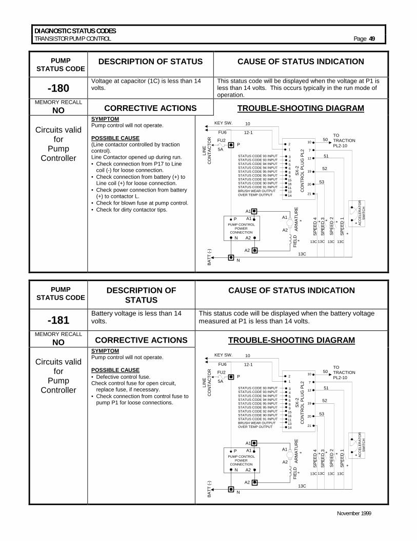
DIAGNOSTIC STATUS CODES TRANSISTOR PUMP CONTROL Page 49
November 1999
PUMP STATUS CODE
DESCRIPTION OF STATUS CAUSE OF STATUS INDICATION
-180 Voltage at capacitor (1C) is less than 14 volts.
This status code will be displayed when the voltage at P1 is less than 14 volts. This occurs typically in the run mode of operation.
MEMORY RECALL NO CORRECTIVE ACTIONS TROUBLE-SHOOTING DIAGRAM
Circuits valid
for Pump
Controller
SYMPTOM Pump control will not operate. POSSIBLE CAUSE (Line contactor controlled by traction control). Line Contactor opened up during run. • =Check connection from P17 to Line
coil (-) for loose connection. • =Check connection from battery (+) to
Line coil (+) for loose connection. • =Check power connection from battery
(+) to contactor L. • =Check for blown fuse at pump control. • =Check for dirty contactor tips.
13C 13C
13C
*
*SPEE
D 2
SPEE
D 1
13C
*
SPEE
D 3
13C
*
SPEE
D 4
ACC
ELER
ATO
RSW
ITC
H
*
ARM
ATU
RE
*
FIEL
D
PUMP CONTROLPOWER
CONNECTION
P A1
A2N
A1
A2
*
A2
A1
N
BATT
(-)
SX-2
CO
NTR
OL
PLU
G P
L2
21
10
12
19
20
21
50
51
TOTRACTIONPL2-10
52
53
7
FU2P
5A
10
12-1
KEY SW.
FU6
LIN
EC
ON
TAC
TOR
STATUS CODE 93 INPUTSTATUS CODE 93 INPUTSTATUS CODE 94 INPUTSTATUS CODE 94 INPUTSTATUS CODE 95 INPUTSTATUS CODE 95 INPUTSTATUS CODE 92 INPUTSTATUS CODE 90 INPUTSTATUS CODE 91 INPUTBRUSH WEAR OUTPUTOVER TEMP OUTPUT
3456891516111314
PUMP STATUS CODE
DESCRIPTION OF STATUS
CAUSE OF STATUS INDICATION
-181 Battery voltage is less than 14 volts.
This status code will be displayed when the battery voltage measured at P1 is less than 14 volts.
MEMORY RECALL NO CORRECTIVE ACTIONS TROUBLE-SHOOTING DIAGRAM
Circuits valid
for Pump
Controller
SYMPTOM Pump control will not operate. POSSIBLE CAUSE • =Defective control fuse. Check control fuse for open circuit,
replace fuse, if necessary. • =Check connection from control fuse to
pump P1 for loose connections.
13C 13C
13C
*
*SPEE
D 2
SPEE
D 1
13C
*
SPEE
D 3
13C
*
SPEE
D 4
ACC
ELER
ATO
RSW
ITC
H
*
ARM
ATU
RE
*
FIEL
D
PUMP CONTROLPOWER
CONNECTION
P A1
A2N
A1
A2
*
A2
A1
N
BATT
(-)
SX-2
CO
NTR
OL
PLU
G P
L2
21
10
12
19
20
21
50
51
TOTRACTIONPL2-10
52
53
7
FU2P
5A
10
12-1
KEY SW.
FU6
LIN
EC
ON
TAC
TOR
STATUS CODE 93 INPUTSTATUS CODE 93 INPUTSTATUS CODE 94 INPUTSTATUS CODE 94 INPUTSTATUS CODE 95 INPUTSTATUS CODE 95 INPUTSTATUS CODE 92 INPUTSTATUS CODE 90 INPUTSTATUS CODE 91 INPUTBRUSH WEAR OUTPUTOVER TEMP OUTPUT
3456891516111314
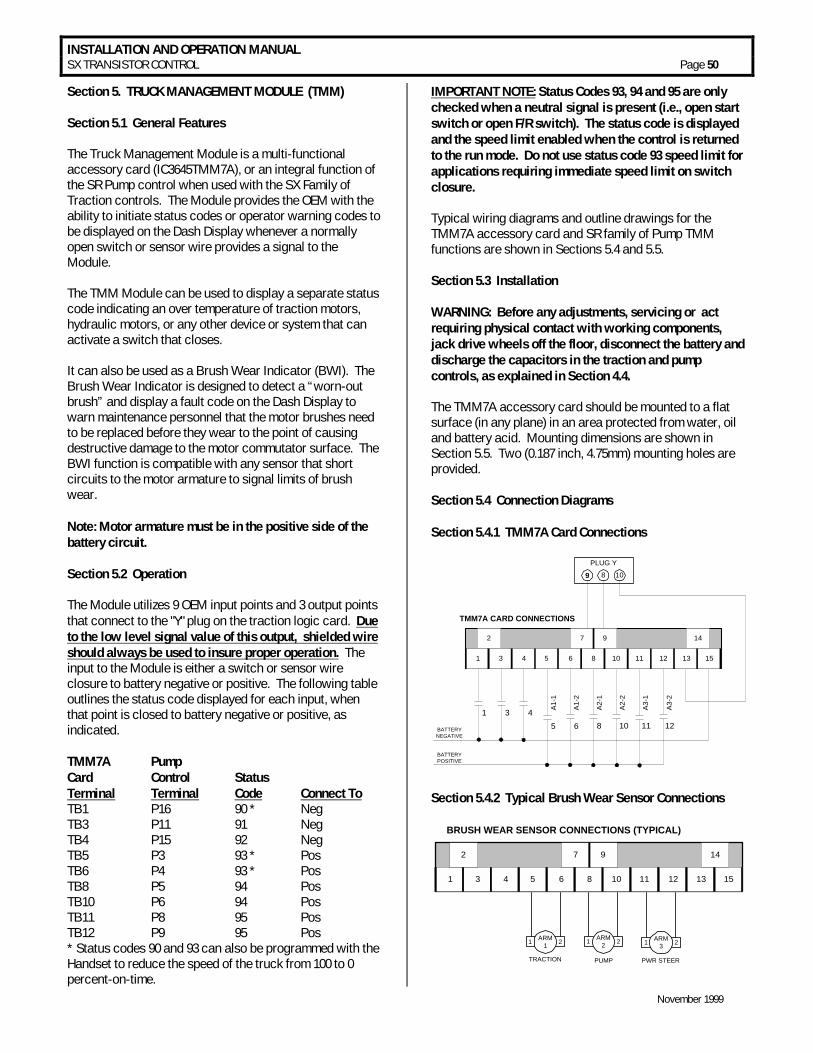
INSTALLATION AND OPERATION MANUAL SX TRANSISTOR CONTROL Page 50
November 1999
Section 5. TRUCK MANAGEMENT MODULE (TMM) Section 5.1 General Features The Truck Management Module is a multi-functional accessory card (IC3645TMM7A), or an integral function of the SR Pump control when used with the SX Family of Traction controls. The Module provides the OEM with the ability to initiate status codes or operator warning codes to be displayed on the Dash Display whenever a normally open switch or sensor wire provides a signal to the Module. The TMM Module can be used to display a separate status code indicating an over temperature of traction motors, hydraulic motors, or any other device or system that can activate a switch that closes. It can also be used as a Brush Wear Indicator (BWI). The Brush Wear Indicator is designed to detect a “worn-out brush” and display a fault code on the Dash Display to warn maintenance personnel that the motor brushes need to be replaced before they wear to the point of causing destructive damage to the motor commutator surface. The BWI function is compatible with any sensor that short circuits to the motor armature to signal limits of brush wear. Note: Motor armature must be in the positive side of the battery circuit. Section 5.2 Operation The Module utilizes 9 OEM input points and 3 output points that connect to the "Y" plug on the traction logic card. Due to the low level signal value of this output, shielded wire should always be used to insure proper operation. The input to the Module is either a switch or sensor wire closure to battery negative or positive. The following table outlines the status code displayed for each input, when that point is closed to battery negative or positive, as indicated. TMM7A Pump Card Control Status Terminal Terminal Code Connect To TB1 P16 90 * Neg TB3 P11 91 Neg TB4 P15 92 Neg TB5 P3 93 * Pos TB6 P4 93 * Pos TB8 P5 94 Pos TB10 P6 94 Pos TB11 P8 95 Pos TB12 P9 95 Pos * Status codes 90 and 93 can also be programmed with the Handset to reduce the speed of the truck from 100 to 0 percent-on-time.
IMPORTANT NOTE: Status Codes 93, 94 and 95 are only checked when a neutral signal is present (i.e., open start switch or open F/R switch). The status code is displayed and the speed limit enabled when the control is returned to the run mode. Do not use status code 93 speed limit for applications requiring immediate speed limit on switch closure. Typical wiring diagrams and outline drawings for the TMM7A accessory card and SR family of Pump TMM functions are shown in Sections 5.4 and 5.5. Section 5.3 Installation WARNING: Before any adjustments, servicing or act requiring physical contact with working components, jack drive wheels off the floor, disconnect the battery and discharge the capacitors in the traction and pump controls, as explained in Section 4.4. The TMM7A accessory card should be mounted to a flat surface (in any plane) in an area protected from water, oil and battery acid. Mounting dimensions are shown in Section 5.5. Two (0.187 inch, 4.75mm) mounting holes are provided. Section 5.4 Connection Diagrams Section 5.4.1 TMM7A Card Connections
1 3 4 5
2 7 9
6 8 10 11 12 13
14
15
BATTERYNEGATIVE
3 45 6 8 1110 12
1089
PLUG Y
BATTERYPOSITIVE
TMM7A CARD CONNECTIONS
9
1 A1-
1
A1-
2
A2-
1
A3-
1
A2-
2
A3-
2
Section 5.4.2 Typical Brush Wear Sensor Connections
1 3 4 5
2 7 9
6 8 10 11 12 13
14
15
BRUSH WEAR SENSOR CONNECTIONS (TYPICAL)
ARM1 21
TRACTION PUMP PWR STEER
ARM2 21 ARM
3 21

INSTALLATION AND OPERATION MANUAL SX TRANSISTOR CONTROL Page 51
November 1999
Section 5.4.3 TMM Pump Control Connections
BATTERYNEGATIVE
3 45 6 8 1110 12
BATTERYPOSITIVE
PUMP CONTROL CONNECTIONS
PA3
PA6
PB6
PA1
PA2
PA4
PA5
PZ10
PZ11
PY10
PA3
1
A1-
1
A1-
2
A2-
1
A3-
1
A2-
2
A3-
2
TO PY10TRACTION
Section 5.4.4 Typical Brush Wear Sensor Connections For Pump Control
ARM1
BRUSH WEAR SENSOR CONNECTIONSFOR PUMP CONTROL (TYPICAL)
PA1
PA2
PA4
PA5
PZ10
PZ11
21
TRACTION PUMP PWR STEER
ARM2 21 ARM
3 21
Section 5.5 TMM7A Outline Drawings
13
45
6
7
2
810
9
1112
14
1315
5.8(147.20)6.15156.20
.8(20.3)
3.36
(85.
3)
x
1.60(40.6)

ADJUSTABLE FEATURES SX TRANSISTOR CONTROLS Page 52
November1999
Section 6. SX FAMILY GE HANDSET INSTRUCTIONS Section 6.1 General Features The GE Handset is a multi-functional tool to be used with the LX, ZX, and SX Series GE solid-state controls. The Handset consists of a Light Emitting Diode (LED) display and a keyboard for data entry. Note: The Handset is the same for all GE controls, however, the cable will change between some control types. Section 6.2 Purpose / Setup Functions The purpose of the Handset is to allow authorized personnel to perform the following functions of the SX family of Controls:
• =Monitor existing system fault codes • =Monitor intermittent random fault codes • =Monitor battery state of charge on systems with BDI • =Monitor hourmeter reading • =Monitor or adjust the following control functions:
♦ = Creep speed ♦ = Armature Controlled Acceleration and 1A Time ♦ = Regenerative Braking Current Limit and Disable ♦ = Armature and Field Current Limit ♦ = Plugging Distance (Current) ♦ = Pedal Position Plug Range or Disable ♦ = 1A Drop Out Current or Disable ♦ = Speed Limit Points ♦ = Truck Management Fault Speed Limit ♦ = Internal Resistance Compensation for Battery
State of Charge Indication ♦ = Battery Voltage ( 36/48 volts is auto ranging ) ♦ = Selection of Card Operation Type.
At the transistor control traction card, unplug the "Y plug" if the dash display is in use, and plug in the Handset to the plug location "Y" on the control card. After installing the Handset tool, plug the battery in and turn the key switch on. The following is the start-up display sequence that will occur:
START-UP DISPLAY SEQUENCE
Key Switch On
Verify Each LED Segment8 8 8 8
If Maintenance CodeIs Active
If Maintenance CodeIs Not Active
Display Code "-99"For Four Seconds andActivate Speed Limit
(if selected)
BDI Display orBlank Display(no BDI used)
Diagnostics OverrideWith Fault
Run Mode
BDI Display orBlank Display(no BDI used)
Diagnostics OverrideWith Fault
Key SwitchOff
Display Traction HourmeterFor Four Seconds
Display Pump HourmeterFor Four Seconds
NOTE: The vehicle can be operated with the Handset connected, however, the adjustment knob must be set fully clockwise to insure the control operates at top speed. Warning: Before making any adjustments to the control, you must consult the operating and maintenance instructions supplied by the vehicle manufacturer. Failure to follow proper set up instructions could result in mis-operation or damage to the control system.
Warning: Before connecting or disconnecting the Handset tool, turn off the key switch, unplug the battery and jack up the drive wheels of the vehicle.
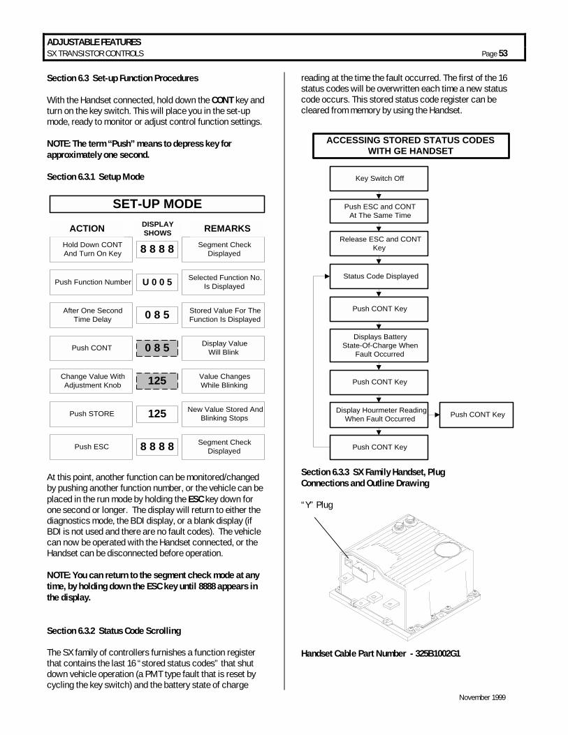
ADJUSTABLE FEATURES SX TRANSISTOR CONTROLS Page 53
November 1999
Section 6.3 Set-up Function Procedures With the Handset connected, hold down the CONT key and turn on the key switch. This will place you in the set-up mode, ready to monitor or adjust control function settings. NOTE: The term “Push” means to depress key for approximately one second. Section 6.3.1 Setup Mode
SET-UP MODE
Hold Down CONTAnd Turn On Key 8 8 8 8 Segment Check
Displayed
ACTION DISPLAYSHOWS REMARKS
Push Function Number U 0 0 5 Selected Function No.Is Displayed
After One SecondTime Delay 0 8 5 Stored Value For The
Function Is Displayed
Push CONT 0 8 5 Display ValueWill Blink
Change Value WithAdjustment Knob
Value ChangesWhile Blinking
Push STORE 125 New Value Stored AndBlinking Stops
Push ESC 8 8 8 8 Segment CheckDisplayed
125
At this point, another function can be monitored/changed by pushing another function number, or the vehicle can be placed in the run mode by holding the ESC key down for one second or longer. The display will return to either the diagnostics mode, the BDI display, or a blank display (if BDI is not used and there are no fault codes). The vehicle can now be operated with the Handset connected, or the Handset can be disconnected before operation. NOTE: You can return to the segment check mode at any time, by holding down the ESC key until 8888 appears in the display. Section 6.3.2 Status Code Scrolling The SX family of controllers furnishes a function register that contains the last 16 “stored status codes” that shut down vehicle operation (a PMT type fault that is reset by cycling the key switch) and the battery state of charge
reading at the time the fault occurred. The first of the 16 status codes will be overwritten each time a new status code occurs. This stored status code register can be cleared from memory by using the Handset.
Key Switch Off
Push ESC and CONTAt The Same Time
Release ESC and CONTKey
Status Code Displayed
Push CONT Key
Displays BatteryState-Of-Charge When
Fault Occurred
Push CONT Key
Display Hourmeter ReadingWhen Fault Occurred
Push CONT Key
Push CONT Key
ACCESSING STORED STATUS CODESWITH GE HANDSET
Section 6.3.3 SX Family Handset, Plug Connections and Outline Drawing “Y” Plug
Handset Cable Part Number - 325B1002G1
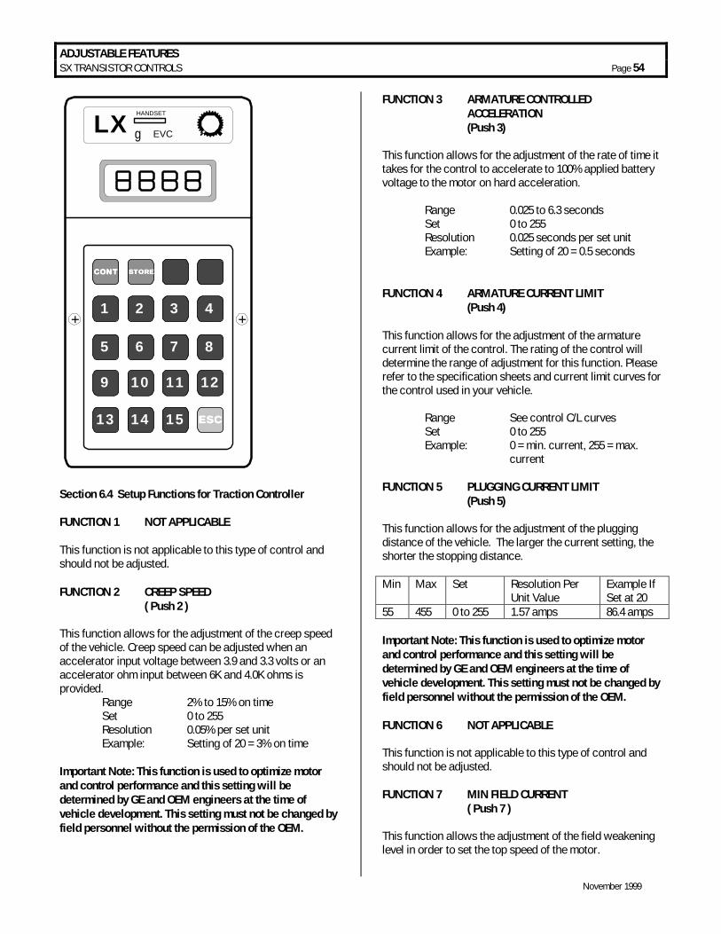
ADJUSTABLE FEATURES SX TRANSISTOR CONTROLS Page 54
November 1999
ESCESCESCESC
LX HANDSET
g EVC
CONTCONTCONTCONT STORESTORESTORESTORE
1
5
+ +
9
13
2
6
10
14
3
7
11
15
4
8
12
Section 6.4 Setup Functions for Traction Controller FUNCTION 1 NOT APPLICABLE This function is not applicable to this type of control and should not be adjusted. FUNCTION 2 CREEP SPEED ( Push 2 ) This function allows for the adjustment of the creep speed of the vehicle. Creep speed can be adjusted when an accelerator input voltage between 3.9 and 3.3 volts or an accelerator ohm input between 6K and 4.0K ohms is provided. Range 2% to 15% on time Set 0 to 255 Resolution 0.05% per set unit Example: Setting of 20 = 3% on time Important Note: This function is used to optimize motor and control performance and this setting will be determined by GE and OEM engineers at the time of vehicle development. This setting must not be changed by field personnel without the permission of the OEM.
FUNCTION 3 ARMATURE CONTROLLED ACCELERATION
(Push 3) This function allows for the adjustment of the rate of time it takes for the control to accelerate to 100% applied battery voltage to the motor on hard acceleration. Range 0.025 to 6.3 seconds Set 0 to 255 Resolution 0.025 seconds per set unit Example: Setting of 20 = 0.5 seconds FUNCTION 4 ARMATURE CURRENT LIMIT (Push 4) This function allows for the adjustment of the armature current limit of the control. The rating of the control will determine the range of adjustment for this function. Please refer to the specification sheets and current limit curves for the control used in your vehicle. Range See control C/L curves Set 0 to 255 Example: 0 = min. current, 255 = max. current FUNCTION 5 PLUGGING CURRENT LIMIT (Push 5) This function allows for the adjustment of the plugging distance of the vehicle. The larger the current setting, the shorter the stopping distance. Min Max Set Resolution Per
Unit Value Example If Set at 20
55 455 0 to 255 1.57 amps 86.4 amps Important Note: This function is used to optimize motor and control performance and this setting will be determined by GE and OEM engineers at the time of vehicle development. This setting must not be changed by field personnel without the permission of the OEM. FUNCTION 6 NOT APPLICABLE This function is not applicable to this type of control and should not be adjusted. FUNCTION 7 MIN FIELD CURRENT ( Push 7 ) This function allows the adjustment of the field weakening level in order to set the top speed of the motor.

ADJUSTABLE FEATURES SX TRANSISTOR CONTROLS Page 55
November 1999
Resolution Volts Min Max Set Per unit value 48 0 60 51 to 255 .314 72/80 0 55 51 to 255 .269
MIN IF = (VAL-51) X .314 (48 VOLT)
Important Note: This function is used to optimize motor and control performance, and this setting will be determined by GE and OEM engineers at the time of vehicle development. This setting must not be changed by field personnel without the permission of the OEM. FUNCTION 8 MAX FIELD CURRENT ( Push 8 ) This function allows for the adjustment of the maximum field current in order to obtain the maximum torque of the motor.
Resolution Volts Min Max Set Per unit value 48 0 60 51 to 255 .314 72/80 0 55 51 to 255 .269
MAX IF = (VAL-51) X .314 (48 VOLT)
Important Note: This function is used to optimize motor and control performance, and this setting will be determined by GE and OEM engineers at the time of vehicle development. This setting must not be changed by field personnel without the permission of the OEM. FUNCTION 9 REGEN BRAKING C/L (Push 9) This function allows for the adjustment of the Regen braking current limit. The higher the current, the shorter the stopping distance.
Resolution Example Volts Min Max Set Per unit value If set at 20 48 183A 597A 0 to 255 (1.625 x
setting) + 183 215 amp
72/80 26A 440A 0 to 255 1.625 x setting 58 amps
REGEN BRAKE IA = (VAL X 1.625) + 183 48 VOLTS FUNCTION 10 FIELD CURRENT FOR REGEN ( Push 10 ) This function allows for the adjustment of the field current to be used during the regen braking mode.
Resolution Example Volts Min Max Set Per unit value If set at 71 48 0 60 51 to 255 .314 6.28A 72/80 0 55 51 to 255 .269 amps 5.38A Important Note: This function is used to optimize motor and control performance and this setting will be determined by GE and OEM engineers at the time of vehicle development. This setting must not be changed by field personnel without the permission of the OEM. FUNCTION 11 MAX ARMATURE % ON (Push 4) This function allows for the adjustment of the motor speed limit (maximum battery volts to the motor) when the SL1 limit switch input signal is received by the control card. The SL1 limit switch is a normally closed switch connected to battery negative; the switch opening enables speed limit. Range 100% to 0% battery volts Set 51 to 180 Resolution 0.78 % per set unit Example Setting of 71 = 84.4 % battery volts FUNCTION 12 NOT APPLICABLE This function is not applicable to this type of control and should not be adjusted. FUNCTION 13 SPEED LIMIT 3 ( Push 13 ) The SL3 set speed limit is activated by the Truck Management Module 90,91 and also status code 99. See Section 5 for Truck Management Module details; Maintenance Speed Limit. FUNCTION 14 INTERNAL RESISTANCE COMPENSATION ( Push 14 ) This function is used when the Battery Discharge Indicator is present. Adjustment of this function will improve the accuracy of the BDI. In order to determine this setting the voltage drop of the battery under load must first be calculated by the following method. This function can be changed by the dash display mode selection button. 1. On a fully charged battery, record the open circuit
voltage (Vo) by measuring the voltage at the control positive and negative power terminals.

ADJUSTABLE FEATURES SX TRANSISTOR CONTROLS Page 56
November 1999
2. Load the traction motor to 100 amps in 1A and record the voltage (VL) at the control positive and negative power terminal.
3. Calculate voltage drop (VDrop) as follows: VDrop = VO - VL
4. Use the table below to determine the appropriate setting using the calculated VDrop as a reference.
INTERNAL RESISTANCE COMPENSATION
TABLE
Setting VDrop Setting VDrop 2 11.44 17 01.34 3 07.60 18 01.27 4 05.72 19 01.20 5 04.57 20 01.14 6 03.81 21 01.09 7 03.27 22 01.04 8 02.86 23 00.99 9 02.54 24 00.95 10 02.28 25 00.91 11 02.08 26 00.88 12 01.90 27 00.85 13 01.76 28 00.82 14 01.63 29 00.79 15 01.52 30 00.76 16 01.43 31 00.74
FUNCTION 15 BATTERY VOLTS (Push l5) This function allows for the adjustment of voltage range for controls equipped with the Battery Discharge Indication function. In order for the BDI to operate properly, the setting as shown in the table must be entered: Battery volts Set units 24 volts Between 0 and 31 36 volts Between 32 and 44 48 volts Between 45 and 69 72 volts Between 70 and 80 80 volts Between 81 and 183 36/48 volts Between 184 and 250 No BDI Between 251 and 255
FUNCTION 16 NOT APPLICABLE This function is not applicable to this type of control and should not be adjusted. FUNCTION 17 CARD TYPE SELECTION ( Push CONT 2 ) This function allows for the selection of the card type used for your vehicle's application. This function should be set at a value of 57 Warning: These settings must be changed by authorized personnel only, following instructions supplied by the vehicle manufacturer. Card type selection must be made within the capabilities of the control panel used and the supporting electro-mechanical devices. Failure to comply with proper application standards could result in mis-operation or damage to the control and/or motors. FUNCTION 18 STEER PUMP TIME DELAY ( Push CONT 3 ) This function allows for the selection of steer pump contactor pick up input, either seat switch or directional switch closing, and adjustment of the time delay for the contactor drop out. • = Pick up steer pump contactor on seat switch closure
and time delay drop out of steer pump contactor on seat switch opening:
Range 1.5 to 65 seconds Setting Between 0 and 128 Resolution 0.5 seconds per set unit Example: Setting of 20 = (20 x 0.5) + 1.5 = 11.5 seconds • = Pick up steer pump contactor on directional switch
closure and time delay drop out of steer pump contactor on directional switch opening:
Range 0.5 to 63 seconds Setting Between 129 and 255 Resolution 0.5 seconds per set unit Example: Setting of 149 = ((149-129) x 0.5) + 1.5 = 11.5 seconds FUNCTION 19 MAINTENANCE CODE TENS AND UNITS
HOURS SET ( Push CONT 4 ) This function allows for the adjustment of the tens and units hours of the maintenance code activation time.
The following functions have function numbers larger than the numbers on the Handset keyboard. To access
these functions. Push the CONT key and the number shown in the following instructions at the same time.
THE SEAT SWITCH MUST BE OPEN.

ADJUSTABLE FEATURES SX TRANSISTOR CONTROLS Page 57
November 1999
Range 0 to 99 Set 0 to 99 Example 9999 Hours FUNCTION 20 MAINTENANCE CODE THOUSANDS
AND HUNDREDS HOURS SET ( Push CONT 5 ) This function allows for the adjustment of the thousands and hundreds hours of the maintenance code activation time. Range 0 to 240 Set 0 to 240 Example 9999 Hours FUNCTION 21 AUTO REGEN BRAKING C/L (Push CONT 6) This function allows for the adjustment of the regen braking current limit when the foot brake is fully depressed
AUTO REGENC/L AMPS
= REGEN C/LVAL
- FNT 21-51VAL
-[( (
6.50
[
FUNCTION 24 FIELD WEAKENING START ( Push CONT 9) This function allows for setting the armature current at which minimum field current will achieved . Range 0 to 414 Amps Setting 0 to 255 Resolution 1.625 per set unit I MOTOR FWS = VAL. x 1.625 Example: Setting of 20 = 32.5 amps FUNCTION 25 MONITOR ( Push CONT 10) This function allows the monitoring of certain control functions by looking directly at the RAM of the microprocessor. Because absolute memory locations need to be known, this function should not be used without detailed instructions from the GE application engineer. This function should only be adjusted by the vehicle OEM. To ensure optimum operation of the control, this function must be left with zero stored in this register. FUNCTION 26 RATIO ( Push CONT 11)
This function sets the ratio between armature and field current when operating below the maximum field current and above the Field Weakening Start point. The setting represents the quantity of field current changed for each 1 amp of armature current changed.
Volts Max Change Set Resolution 48 .48 0 to 40 .012
Example : Setting of 20 = 20 x .012 = .24 field amps/arm. amp FUNCTION 28 STORED STATUS CODE COUNT POINTER ( Push CONT 13) This register contains the location of the last stored status code recorded of the 16 stored status codes. These stored status codes have caused a PMT controller shutdown and/or disruption of normal vehicle operation. To determine which stored status code was the last one recorded, read the number stored in Function 28. Using the Memory Map for your logic card, match the "stored status code pointer number" [the number shown in (bold italics) in the HS (Handset) number column] on the memory map, with the number obtained from Function 28. This will be the last stored status code recorded. Note: When scrolling through the stored status code register, the register always starts at status code 1 and scrolls to status code 16. Instructions for scrolling the register are in section 6.3.2 of this instruction booklet.
FUNCTION 48 MODE 1 (TURTLE) - ARMATURE CONTROLLED ACCELERATION ( Push CONT 1)
DASH DISPLAY INTERACTIVE MODES The following functions (functions 48 through 62) are mode settings that are activated from the Interactive Dash Display. Each function must be set using the logic table shown below. If you try to set this function outside these guidelines, an error code will be displayed to prompt you to enter the correct setting: If “80” is displayed, the setting is too low. If “81” is displayed, the setting is too high.
The following functions have function numbers larger than the numbers on the Handset keyboard. To access
these functions. Push the CONT key and the number shown in the following instructions at the same time.
THE SEAT SWITCH MUST BE CLOSED.

ADJUSTABLE FEATURES SX TRANSISTOR CONTROLS Page 58
November 1999
This function allows for the adjustment of the rate of time it takes for the control to accelerate to 100% applied battery voltage to the motor on hard acceleration. Range 0.025 to 6.3 seconds Set 0 to 255 Resolution 0.025 seconds per set unit Example: Setting of 20 = 0.5 seconds This CA takes effect when the Mode 1 settings are called for by the interactive Dash Display . FUNCTION 49 MODE 1 FIELD WEAKENING START ( Push CONT 2) This function allows for setting the armature current at which minimum field current will be achieved . Range 0 to 414 Amps Setting 0 to 255 Resolution 1.625 per set unit Example: Setting of 20 = 32.5 amps I M FWS = VAL x 1.625 This FIELD WEAKENING START takes effect when the Mode 1 settings are called for by the interactive Dash Display. FUNCTION 50 MODE 1 MIN FIELD CURRENT ( Push CONT 3 ) This function allows the adjustment of the field weakening level in order to set the top speed of the motor.
Resolution Volts Min Max Set Per unit value 48 0 60 51 to 255 .314 72/80 0 55 51 to 255 .269
MIN IF = (VAL-51) X .314 (48 VOLT)
This MIN FIELD CURRENT takes effect when the Mode 1 settings are called for by the interactive Dash Display. FUNCTION 51 MODE 1 MAX ARMATURE % ON ( Push CONT 4) This function allows for the adjustment of the speed limit (maximum battery volts to the motor) when the SL1 limit switch input signal is received by the control card. The SL1 limit switch is a normally closed switch connected to battery negative; the switch opening enables speed limit.
Range 100% to 0% battery volts Set 51 to 180 Resolution 0.78 % per set unit Example Setting of 71 = 84.4 % battery volts This MAX ARMATURE % ON takes effect when the Mode 1 settings are called for by the interactive Dash Display. FUNCTION 52 MODE 2 ARMATURE CONTROLLED ACCELERATION ( Push CONT 5) Same as Function 48. This CA takes effect when the Mode 2 settings are called for by the interactive Dash Display. FUNCTION 53 MODE 2 FIELD WEAKENING START ( Push CONT 6) Same as Function 49. This FIELD WEAKENING START takes effect when the Mode 2 settings are called for by the interactive Dash Display. FUNCTION 54 MODE 2 MIN FIELD CURRENT ( Push CONT 7 ) Same as Function 50. This MIN FIELD CURRENT takes effect when the Mode 2 settings are called for by the interactive Dash Display. FUNCTION 55 MODE 2 MAX ARMATURE % ON ( Push CONT 8 ) Same as Function 51. This MAX ARMATURE % ON takes effect when the Mode 2 settings are called for by the interactive Dash Display. FUNCTION 56 MODE 3 ARMATURE CONTROLLED ACCELERATION ( Push CONT 9) Same as Function 48. This CA takes effect when the Mode 3 settings are called for by the interactive Dash Display. FUNCTION 57 MODE 3 FIELD WEAKENING START ( Push CONT 10) Same as Function 49.
ADJUSTABLE FEATURES SX TRANSISTOR CONTROLS Page 59
November 1999
This FIELD WEAKENING START takes effect when the Mode 3 settings are called for by the interactive Dash Display. FUNCTION 58 MODE 3 MIN FIELD CURRENT ( Push CONT 11 ) Same as Function 50. This MIN FIELD CURRENT takes effect when the Mode 3 settings are called for by the interactive Dash Display. FUNCTION 59 MODE 3 MAX ARMATURE % ON ( Push CONT 12 ) Same as Function 51. This MAX ARMATURE % ON takes effect when the Mode 3 settings are called for by the interactive Dash Display. FUNCTION 60 MODE 4 ARMATURE CONTROLLED ACCELERATION ( Push CONT 13) Same as Function 48. This CA takes effect when the Mode 4 settings are called for by the interactive Dash Display. FUNCTION 61 MODE 4 FIELD WEAKENING START ( Push CONT 14) Same as Function 49. This FIELD WEAKENING START takes effect when the Mode 4 settings are called for by the interactive Dash Display. FUNCTION 62 MODE 4 MIN FIELD CURRENT ( Push CONT 15 ) Same as Function 50. This MIN FIELD CURRENT takes effect when the Mode 4 settings are called for by the interactive Dash Display. FUNCTION 63 MODE 4 MAX ARMATURE % ON ( Push CONT ESC ) Same as Function 51. This MAX ARMAURE % ON takes effect when the Mode 4 settings are called for by the interactive Dash Display.
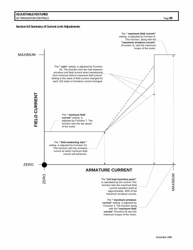
ADJUSTABLE FEATURES SX TRANSISTOR CONTROLS Page 60
November 1999
Section 6.5 Summary of Current Limit Adjustments
ZERO
MAXIMUM
ZER
O
MAX
IMU
M
FIEL
D C
UR
REN
T
ARMATURE CURRENT
The " minimum fieldcurrent" setting isadjusted by Function 7. Thefunction sets the top speedof the motor.
The " maximum field current"setting is adjusted by Function 8.
This function, along with the"maximum armature current"(Function 4), sets the maximum
torque of the motor.
The " maximum armaturecurrent" setting is adjusted byFunction 4. The function along
with the "maximum fieldcurrent" (Function 8) sets themaximum torque of the motor.
The " field weakening start "setting is adjusted by Function 24.
This function sets the armaturecurrent at which minimum field
current will achieved .
The " ratio" setting is adjusted by Function26. This function sets the ratio between
armature and field current when transitioningfrom minimum field to maximum field current.
Setting is the value of field current changed foreach 100 amps of armature current changed.
The "full load transition point"is calculated by the control. Thisfunction sets the maximum field
current transition point atapproximately 80% of the
maximum armature current.

ADJUSTABLE FEATURES TRANSISTOR PUMP CONTROLS Page 61
November 1999
Section 6.6 Setup Functions for Hydraulic Pump Control FUNCTION 1: NOT APPLICABLE This function is not applicable to this type of control and should not be adjusted. FUNCTION 2: INTERNAL RESISTANCE COMPENSATION START (Push 2) This function allows for the adjustment of the current level at which the internal resistance compensation feature (Function 16) will take effect. Range 0 to 1325 amps Setting 52 to 255 Resolution 6.5 amps per set unit Example: Setting of 72 = (72-52) x 6.5 = 130 amps FUNCTION 3: CONTROLLED ACCELERATION (Push 3) This function allows for the adjustment of the rate of time it takes for the control to accelerate to 96% applied battery voltage to the motor on hard acceleration. Range 0.1 to 5.5 seconds Setting 0 to 255 Resolution 0.021 seconds per set unit Example: Setting of 20 = 0.52 seconds C/A FUNCTION 4: CURRENT LIMIT (Push 4) This function allows for the adjustment of the current limit of the control. The rating of the control will determine the range of adjustment for this function. Please refer to the OEM operating instructions for the control used in your vehicle. Range See OEM control C/L curves Setting 0 to 255 Example: 0 = min. current, 255 = max. current FUNCTION 7: INTERNAL RESISTANCE COMPENSATION RATE (Push 7) This function allows for the adjustment of the rate of time it takes for the control to add the internal resistance compensation voltage that is applied to the motor. This function will add 0.375 volts to the motor at the rate of time
adjusted until the total IR compensation voltage has been added. Range 0.0015 to 0.383 seconds Setting 0 to 255 Resolution 0.0015 seconds per set unit Example: Setting of 20 = 0.032 seconds For example, if you had selected 2.08 volts from Function 16 to be added to the motor, it would take 0.18 seconds to add a total of 2.08 volts. (2.08/0.375)=0.032 FUNCTION 11: SPEED LIMIT 1 (SL1) (Push 11) This function allows for the adjustment of the speed limit (maximum battery volts to the motor) when the SL1 limit switch input signal is received by the control card. SL1 limit switch is a normally open switch connected to battery negative, the switch closing enables speed limit. Range 0% to 100% battery volts Setting 0 to 255 Resolution 0.375 volts per set unit Example: Setting of 50=18.75 volts FUNCTION 12: SPEED LIMIT 2 (SL2) (Push 12) Same as Function 11 except using SL2 limit switch for input. FUNCTION 13: SPEED LIMIT 3 (SL3) (Push 13) Same as Function 11 except using SL3 limit switch for input. FUNCTION 14: NOT APPLICABLE This function is not applicable to this type of control and should not be adjusted.
FUNCTION 16: SPEED / TORQUE COMPENSATION (Push CONT 1) This function is used to stabilize pump speed at heavy loads. The voltage selected will be added to the motor at each 100 amp increment starting at the value set in Function 2. The voltage compensation selected will be added in increments of 0.375 volts until the entire voltage is added. For example, a setting of 2 will be added in 30 steps
Note: The following functions have function numbers larger than the numbers on the Handset keyboard. To access these functions, push the CONT key and the number shown in the following instructions at the same time. THE KEY SWITCH MUST BE OPEN.
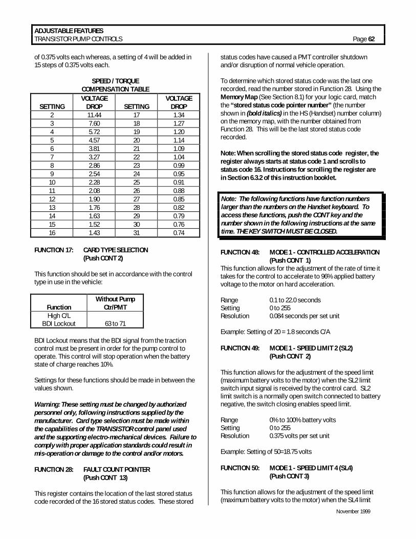
ADJUSTABLE FEATURES TRANSISTOR PUMP CONTROLS Page 62
November 1999
of 0.375 volts each whereas, a setting of 4 will be added in 15 steps of 0.375 volts each.
SPEED / TORQUE COMPENSATION TABLE
SETTING
VOLTAGE DROP
SETTING
VOLTAGE DROP
2 11.44 17 1.34 3 7.60 18 1.27 4 5.72 19 1.20 5 4.57 20 1.14 6 3.81 21 1.09 7 3.27 22 1.04 8 2.86 23 0.99 9 2.54 24 0.95 10 2.28 25 0.91 11 2.08 26 0.88 12 1.90 27 0.85 13 1.76 28 0.82 14 1.63 29 0.79 15 1.52 30 0.76 16 1.43 31 0.74
FUNCTION 17: CARD TYPE SELECTION
(Push CONT 2) This function should be set in accordance with the control type in use in the vehicle:
Function
Without Pump Ctr/PMT
High C/L BDI Lockout
63 to 71
BDI Lockout means that the BDI signal from the traction control must be present in order for the pump control to operate. This control will stop operation when the battery state of charge reaches 10%. Settings for these functions should be made in between the values shown. Warning: These setting must be changed by authorized personnel only, following instructions supplied by the manufacturer. Card type selection must be made within the capabilities of the TRANSISTOR control panel used and the supporting electro-mechanical devices. Failure to comply with proper application standards could result in mis-operation or damage to the control and/or motors. FUNCTION 28: FAULT COUNT POINTER (Push CONT 13) This register contains the location of the last stored status code recorded of the 16 stored status codes. These stored
status codes have caused a PMT controller shutdown and/or disruption of normal vehicle operation. To determine which stored status code was the last one recorded, read the number stored in Function 28. Using the Memory Map (See Section 8.1) for your logic card, match the “stored status code pointer number” (the number shown in (bold italics) in the HS (Handset) number column) on the memory map, with the number obtained from Function 28. This will be the last stored status code recorded. Note: When scrolling the stored status code register, the register always starts at status code 1 and scrolls to status code 16. Instructions for scrolling the register are in Section 6.3.2 of this instruction booklet.
FUNCTION 48: MODE 1 - CONTROLLED ACCELERATION (Push CONT 1) This function allows for the adjustment of the rate of time it takes for the control to accelerate to 96% applied battery voltage to the motor on hard acceleration. Range 0.1 to 22.0 seconds Setting 0 to 255 Resolution 0.084 seconds per set unit Example: Setting of 20 = 1.8 seconds C/A FUNCTION 49: MODE 1 - SPEED LIMIT 2 (SL2) (Push CONT 2) This function allows for the adjustment of the speed limit (maximum battery volts to the motor) when the SL2 limit switch input signal is received by the control card. SL2 limit switch is a normally open switch connected to battery negative, the switch closing enables speed limit. Range 0% to 100% battery volts Setting 0 to 255 Resolution 0.375 volts per set unit Example: Setting of 50=18.75 volts FUNCTION 50: MODE 1 - SPEED LIMIT 4 (SL4) (Push CONT 3) This function allows for the adjustment of the speed limit (maximum battery volts to the motor) when the SL4 limit
Note: The following functions have function numbers larger than the numbers on the Handset keyboard. To access these functions, push the CONT key and the number shown in the following instructions at the same time. THE KEY SWITCH MUST BE CLOSED.

ADJUSTABLE FEATURES TRANSISTOR PUMP CONTROLS Page 63
November 1999
switch input signal is received by the control card. SL4 limit switch is a normally open switch connected to battery negative, the switch closing enables speed limit. Range 0% to 100% battery volts Setting 0 to 255 Resolution 0.375 volts per set unit Example: Setting of 50=18.75 volts FUNCTION 51 NOT APPLICABLE This function is not applicable to this type of control and should not be adjusted. FUNCTION 52: MODE 2 - CONTROLLED ACCELERATION (Push CONT 5) Same as Function 48. FUNCTION 53: MODE 2 - SPEED LIMIT 2 (SL2) (Push CONT 6) Same as Function 49. FUNCTION 54: MODE 2 - SPEED LIMIT 4 (SL4) (Push CONT 7) Same as Function 50. FUNCTION 55: NOT APPLICABLE This function is not applicable to this type of control and should not be adjusted. FUNCTION 56: MODE 3 - CONTROLLED ACCELERATION (Push CONT 9) Same as Function 48. FUNCTION 57: MODE 3 - SPEED LIMIT 2 (SL2) (Push CONT 10) Same as Function 49. FUNCTION 58: MODE 3 - SPEED LIMIT 4 (SL4) (Push CONT 11) Same as Function 50. FUNCTION 59: NOT APPLICABLE This function is not applicable to this type of control and should not be adjusted. FUNCTION 60: MODE 4 - CONTROLLED ACCELERATION
(Push CONT 13) Same as Function 48. FUNCTION 61: MODE 4 - SPEED LIMIT 2 (SL2) (Push CONT 14) Same as Function 49. FUNCTION 62: MODE 4 - SPEED LIMIT 4 (SL4) (Push CONT 15) Same as Function 50.

INSTALLATION AND OPERATION MANUAL SX TRANSISTOR CONTROL Page 64
November1999
Section 7. DASH DISPLAYS Section 7.1 Application The SX family Standard and Interactive Dash Displays allow the operator and maintenance personnel easy access to truck operation information and real-time system diagnostics of the controller, motor and various accessories. Hourmeter readings, battery discharge information, maintenance information and system status codes are clearly displayed during startup and running modes. Shielded cable connections are made to the Dash Display by means of five (5) 22-gage wires to the “Y” Plug of the traction and hydraulic pump controls. Section 7.2 Standard Dash Displays
The GE Standard Dash Display is a four segment Light Emitting Diode (LED) instrument that displays the GE LX, ZX, and SX Status Codes, Hourmeter Readings, Battery Discharge Indication, and Maintenance Required Code. The four LED's above the symbols indicate the active readout mode. Section 7.3 Interactive Custom Dash Displays
The Interactive Custom Dash Display allows the operator to select the best vehicle performance for changing factory (task) conditions. There are four (4) “operator interaction modes” that can be selected by depressing a push-button on the dash display.
From the Dash Display, the operator may select any of four pre-set interactive modes consisting of (4) Controlled Acceleration levels, (4) Field Weakening Pick Up levels and (4) Speed Limit levels. These interactive modes are “pre-set” using the Handset (Functions 48 - 63) or a personal computer (Functions 97 - 112). This feature allows the operator to select the best vehicle performance for changing factory (task) conditions. The Custom Dash Display incorporates all the features and functions of the Standard Dash Display, in addition to the following customer options: • = LED graphics to display Battery Discharge Indication
status. • =Various LED indicators for Maintenance Required Status
Codes. These can include options for traction, pump and power steer motors, hourmeter, over-temperature, seat belt, brake and other safety sensors.
• =A push-button associated with the four segment LED that displays Status Codes can be used to scroll the last 16 “Stored Status Codes” that shut down vehicle operation with a PMT fault.
Connections Connections are made to the Dash Display with five (5) 22-gage wires to Plug "Y" of each control. Shielded cable is required to eliminate signal interference. Part Number
IC3645LXTDD T 3
T=Traction OnlyP=Traction & Pump
3=Round Face with four display symbols
For Custom Dash Displays,contact your vehicleOEM.
Reference AMP#102241-3 Dash Display mating plug AMP#1-87195-8 Dash Display mating pin 44A723596-G09 Dash Display plug kit AMP#175965-2 "Y" Plug AMP#175180-1 "Y" Plug receptacle
g GE Electric VehicleMotors & Controls
+ -
BA
TTE
RY
+
-
PUSH
PUSH
EVT100ZX

INSTALLATION AND OPERATION MANUAL SX TRANSISTOR CONTROL Page 65
November1999
Section 7.4 Start-Up Display Sequence
START-UP DISPLAY SEQUENCE
Key Switch On
Verify Each LED Segment8 8 8 8
If Maintenance CodeIs Active
If Maintenance CodeIs Not Active
Display Code "-99"For Four Seconds andActivate Speed Limit
(if selected)
BDI Display orBlank Display(no BDI used)
Diagnostics OverrideWith Fault
Run Mode
BDI Display orBlank Display(no BDI used)
Diagnostics OverrideWith Fault
Key SwitchOff
Display Traction HourmeterFor Four Seconds
Display Pump HourmeterFor Four Seconds
Section 7.5 Outline Drawings
g GE Electric VehicleMotors & Controls
+ -
PY3PY4PY2PY1PY5
1 2 3 4 5
5 4 3 2 1
PY3PY4PY2PY1PUMP
TRACTION
BACK VIEW OF DISPLAY
Wiring connections to "Y"plugs of Traction & Pumpcontrols.
2.45
(62.
2)
3.20 (81.3)
0.19(4.8)
2.00
(50.
8)
PUMP
TRACTION
CONNECTOR OMITTEDIF NOT REQUIRED
0.41(10.4)
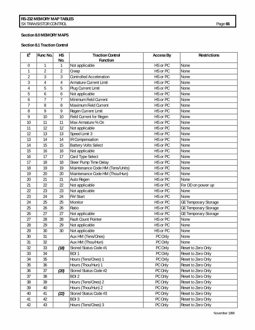
RS-232 MEMORY MAP TABLES SX TRANSISTOR CONTROL Page 66
November 1999
Section 8.0 MEMORY MAPS Section 8.1 Traction Control
E2 Func No. HS No.
Traction Control Function
Access By Restrictions
0 1 1 Not applicable HS or PC None 1 2 2 Creep HS or PC None 2 3 3 Controlled Acceleration HS or PC None 3 4 4 Armature Current Limit HS or PC None 4 5 5 Plug Current Limit HS or PC None 5 6 6 Not applicable HS or PC None 6 7 7 Minimum Field Current HS or PC None 7 8 8 Maximum Field Current HS or PC None 8 9 9 Regen Current Limit HS or PC None 9 10 10 Field Current for Regen HS or PC None
10 11 11 Max Armature % On HS or PC None 11 12 12 Not applicable HS or PC None 12 13 13 Speed Limit 3 HS or PC None 13 14 14 IR Compensation HS or PC None 14 15 15 Battery Volts Select HS or PC None 15 16 16 Not applicable HS or PC None 16 17 17 Card Type Select HS or PC None 17 18 18 Steer Pump Time Delay HS or PC None 18 19 19 Maintenance Code HM (Tens/Units) HS or PC None 19 20 20 Maintenance Code HM (Thou/Hun) HS or PC None 20 21 21 Auto Regen HS or PC None 21 22 22 Not applicable HS or PC For DD on power up 22 23 23 Not applicable HS or PC None 23 24 24 FW Start HS or PC None 24 25 25 Monitor HS or PC GE Temporary Storage 25 26 26 Ratio HS or PC GE Temporary Storage 26 27 27 Not applicable HS or PC GE Temporary Storage 27 28 28 Fault Count Pointer HS or PC None 28 29 29 Not applicable HS or PC None 29 30 30 Not applicable HS or PC None 30 31 Aux HM (Tens/Ones) PC Only None 31 32 Aux HM (Thou/Hun) PC Only None 32 33 (18) Stored Status Code #1 PC Only Reset to Zero Only 33 34 BDI 1 PC Only Reset to Zero Only 34 35 Hours (Tens/Ones) 1 PC Only Reset to Zero Only 35 36 Hours (Thou/Hun) 1 PC Only Reset to Zero Only 36 37 (20) Stored Status Code #2 PC Only Reset to Zero Only 37 38 BDI 2 PC Only Reset to Zero Only 38 39 Hours (Tens/Ones) 2 PC Only Reset to Zero Only 39 40 Hours (Thou/Hun) 2 PC Only Reset to Zero Only 40 41 (22) Stored Status Code #3 PC Only Reset to Zero Only 41 42 BDI 3 PC Only Reset to Zero Only 42 43 Hours (Tens/Ones) 3 PC Only Reset to Zero Only

RS-232 MEMORY MAP TABLES SX TRANSISTOR CONTROL Page 67
November 1999
E2 Func No. HS No.
Traction Control Function
Access By Restrictions
43 44 Hours (Thou/Hun) 3 PC Only Reset to Zero Only 45 46 BDI 4 PC Only Reset to Zero Only 46 47 Hours (Tens/Ones) 4 PC Only Reset to Zero Only 47 48 Hours (Thou/Hun) 4 PC Only Reset to Zero Only 48 49 (26) Stored Status Code #5 PC Only Reset to Zero Only 49 50 BDI 5 PC Only Reset to Zero Only 50 51 Hours (Tens/Ones) 5 PC Only Reset to Zero Only 51 52 Hours (Thou/Hun) 5 PC Only Reset to Zero Only 52 53 (28) Stored Status Code #6 PC Only Reset to Zero Only 53 54 BDI 6 PC Only Reset to Zero Only 54 55 Hours(Tens/Ones) 6 PC Only Reset to Zero Only 55 56 Hours(Thou/Hun) 6 PC Only Reset to Zero Only 56 57 (30) Stored Status Code #7 PC Only Reset to Zero Only 57 58 BDI 7 PC Only Reset to Zero Only 58 59 Hours(Tens/Ones) 7 PC Only Reset to Zero Only 59 60 Hours(Thou/Hun) 7 PC Only Reset to Zero Only 60 61 (32) Stored Status Code #8 PC Only Reset to Zero Only 61 62 BDI 8 PC Only Reset to Zero Only 62 63 Hours;(Tens/Ones) 8 PC Only Reset to Zero Only 63 64 Hours(Thou/Hun) 8 PC Only Reset to Zero Only 64 65 (34) Stored Status Code #9 PC Only Reset to Zero Only 65 66 BDI 9 PC Only Reset to Zero Only 66 67 Hours(Tens/Ones) 9 PC Only Reset to Zero Only 67 68 Hours(Thou/Hun) 9 PC Only Reset to Zero Only 68 69 (36) Stored Status Code #10 PC Only Reset to Zero Only 69 70 BDI 10 PC Only Reset to Zero Only 70 71 Hours(Tens/Ones) 10 PC Only Reset to Zero Only 71 72 Hours(Thou/Hun) 10 PC Only Reset to Zero Only 72 73 (38) Stored Status Code #11 PC Only Reset to Zero Only 73 ; 74 BDI 11 PC Only Reset to Zero Only 74 75 Hours(Tens/Ones) 11 PC Only Reset to Zero Only 75 76 Hours(Thou/Hun) 11 PC Only Reset to Zero Only 76 77 (40) Stored Status Code #12 PC Only Reset to Zero Only 77 78 BDI 12 PC Only Reset to Zero Only 78 79 Hours(Tens/Ones) 12 PC Only Reset to Zero Only 79 80 . Hours(Thou/Hun) 12 PC Only Reset to Zero Only 80 81 (42) Stored Status Code #13 PC Only Reset to Zero Only 81 82 BDI 13 PC Only Reset to Zero Only 82 83 Hours(Tens/Ones) 13 PC Only Reset to Zero Only 83 84 Hours(Thou/Hun) 13 PC Only Reset to Zero Only 84 85 (44) Stored Status Code # 14 PC Only Reset to Zero Only 85 86 BDI 14 PC Only Reset to Zero Only 86 87 Hours(Tens/Ones) 14 PC Only Reset to Zero Only 87 88 Hours(Thou/Hun) 14 PC Only Reset to Zero Only 88 89 (46) Stored Status Code # 15 PC Only Reset to Zero Only 89 90 BDI 15 PC Only Reset to Zero Only 90 91 Hours (Tens/Ones) 15 PC Only Reset to Zero Only

RS-232 MEMORY MAP TABLES SX TRANSISTOR CONTROL Page 68
November 1999
E2 Func No. HS No.
Traction Control Function
Access By Restrictions
90 91 Hours (Tens/Ones) 15 PC Only Reset to Zero Only 91 92 Hours (Thou/Hun) 15 PC Only Reset to Zero Only 92 93 (48) Stored Status Code #16 PC Only Reset to Zero Only 94 95 Hours (Tens/Ones) 16 PC Only Reset to Zero Only 95 96 Hours (Thou/Hun) 16 PC Only Reset to Zero Only 96 67 48 Dash Display CA-1 97 98 49 Dash Display FWS-1 HS or PC None 98 99 50 Dash Display Ratio2-1 HS or PC None 99 100 51 Dash Display Speed Limit 2 - 1 HS or PC None 100 101 52 Dash Display CA-2 HS or PC None 101 102 53 Dash Display FWS-2 HS or PC None 102 103 54 Dash Display Ratio2-2 HS or PC None 103 104 55 Dash Display Speed Limit 2 - 2 HS or PC None 104 105 56 Dash Display CA-3 HS or PC None 105 106 57 Dash Display FWS-3 HS or PC None 106 107 58 Dash Display Ratio2-3 HS or PC None 107 108 59 Dash Display Speed Limit 2 - 3 HS or PC None 108 109 60 Dash Display CA-4 HS or PC None 109 110 61 Dash Display FWS-4 HS or PC None 110 111 62 Dash Display Ratio2-4 HS or PC None 111 112 63 Dash Display Speed Limit 2 - 4 HS or PC None 112 113 Secure HM (Tens/Ones) PC Only OEM Read Only 113 114 Secure HM (Thou/Hun) PC Only OEM Read Only 114 115 Secure Aux HM (Tens/Ones) PC Only OEM Read Only 115 116 Secure Aux HM (Thou/Hun) PC Only OEM Read Only 116 117 Reserved PC Only GE Future Use 117 118 Reserved PC Only GE Future Use 118 119 Reserved PC Only GE Future Use 119 120 Reserved PC Only GE Future Use 120 121 OEM Use PC Only None 121 122 OEM Use PC Only None 122 123 OEM Use PC Only None 123 124 OEM Use PC Only None 124 125 OEM Use PC Only None 125 126 OEM Use PC Only None 126 127 OEM Use PC Only None 127 128 OEM Use PC Only None
Numbers in (bold italics) are Stored Status Code pointers.