Embed Size (px)
Citation preview
Senior Design Presentation
Direct Fe Reduction Iron Plant
Group Golf
Selimos, Blake A.
Arrington, Deisy C.
Sink, Brandon
Ciarlette, Dominic F. (Scribe)
Advisor : Orest Romaniuk
Group Meeting 1 – 01/29/2013
2
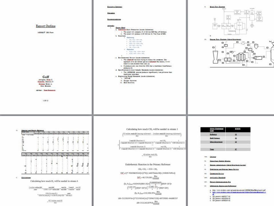
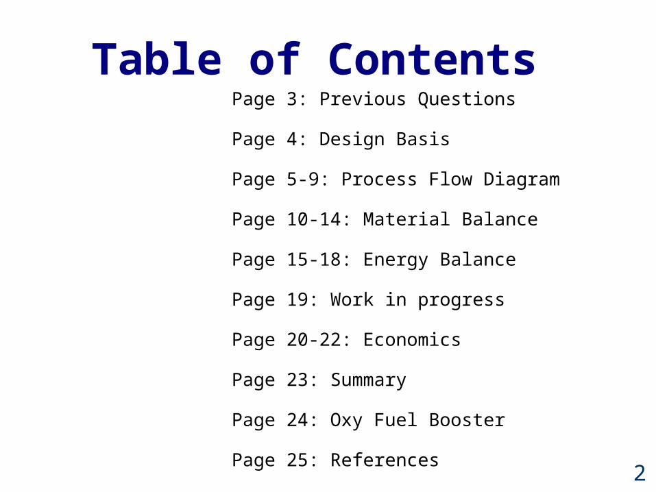
Table of ContentsPage 3: Previous Questions
Page 4: Design Basis
Page 5-9: Process Flow Diagram
Page 10-14: Material Balance
Page 15-18: Energy Balance
Page 19: Work in progress
Page 20-22: Economics
Page 23: Summary
Page 24: Oxy Fuel Booster
Page 25: References

3
Previous QuestionsWill Sulfur in the methane stream poison the
Nickel catalysis?
What is our ore source?
What is the largest Midrex plant currently in operation?
What are our power requirements?

4
Design Basis
• 2 million metric tons DRI produced yearly
• Receive methane from Gas Treatment Plant
• Receive oxygen from Air Separation Plant
• Send CO2 to Gas Cleanup Water Reuse Plant

5
Flow Diagram
Oxy Fuel Boost Reformer
Removal
GuardBed
Heater
Shaft Furnace
Top Gas Scrubber
Midrex Reformer
Main Air
Ejector Stack
Iron Ore
Iron Briquettes
Compressor
Fuel Gas
Recycle1.
2.
3.
4.
5.
6.
7.
9.10.
11.
12. 21.
14.
15.
16.
17.
18.
19.
20.
13.
22.
2
24.
8.

6
Flow Diagram - Reformers

7
Flow Diagram – Top Gases
Removal
Top Gas Scrubber
Compressor
Fuel Gas
Recycle9.10.
17.
18.
8.
13.
7.

8
Flow Diagram – Feed/Heat Recovery

9
Flow Diagram - Furnace
Shaft Furnace
Iron Ore
Iron Briquettes
6.
7.
19.
20.
6.

10
2𝑚𝑖𝑙𝑙𝑖𝑜𝑛𝑚𝑇𝑜𝑛𝐷𝑅𝐼𝑦𝑒𝑎𝑟
×𝑚𝑜𝑙𝐷𝑅𝐼
5.585×10⁻⁵𝑚𝑇𝑜𝑛𝐷𝑅𝐼×
𝑚𝑜𝑙𝐹𝑒𝑚𝑜𝑙𝐷𝑅𝐼
×3𝑚𝑜𝑙𝑂2𝑚𝑜𝑙 𝐹𝑒
×𝑚𝑜𝑙𝐻 2𝑚𝑜𝑙𝑂
Calculating how much H2 will be needed in stream 6
Hand Calculations

11
Hand Calculations (2)
( 57𝑚𝑖𝑙𝑙𝑖𝑜𝑛𝑚𝑜𝑙𝑠𝐶𝑂 (𝑙𝑒𝑎𝑣𝑖𝑛𝑔𝑟𝑒𝑓𝑜𝑟𝑚𝑒𝑟 )𝑑𝑎𝑦
−2𝑚𝑖𝑙𝑙𝑖𝑜𝑛𝑚𝑜𝑙𝑠𝐶𝑂 (𝑒𝑛𝑡𝑒𝑟𝑖𝑛𝑔𝑟𝑒𝑓𝑜𝑟𝑚𝑒𝑟 )
𝑑𝑎𝑦 )
¿45𝑚𝑖𝑙𝑙𝑖𝑜𝑛𝑚𝑜𝑙𝑠𝐶𝐻4
𝑑𝑎𝑦
×[ 2𝑚𝑜𝑙𝐶𝑂 (𝑅𝑒𝑎𝑐𝑡𝑖𝑜𝑛1 )2𝑚𝑜𝑙𝐶𝑂 (𝑅𝑒𝑎𝑐𝑡𝑖𝑜𝑛1 )+1𝑚𝑜𝑙𝐶𝑂 (𝑅𝑒𝑎𝑐𝑡𝑖𝑜𝑛2 )
×𝑚𝑜𝑙𝐶𝐻 4
2𝑚𝑜𝑙𝐶𝑂 (𝑅𝑒𝑎𝑐𝑡𝑖𝑜𝑛1 )×
10.80 (𝑅𝑒𝑎𝑐𝑡𝑖𝑜𝑛1 )
¿+1𝑚𝑜𝑙𝐶𝑂 (𝑅𝑒𝑎𝑐𝑡𝑖𝑜𝑛2 )
2𝑚𝑜𝑙𝐶𝑂 (𝑅𝑒𝑎𝑐𝑡𝑖𝑜𝑛1 )+1𝑚𝑜𝑙𝐶𝑂 (𝑅𝑒𝑎𝑐𝑡𝑖𝑜𝑛2 )×
𝑚𝑜𝑙𝐶𝐻 4
1𝑚𝑜𝑙𝐶𝑂 (𝑅𝑒𝑎𝑐𝑡𝑖𝑜𝑛 2 )×
10.80 (𝑅𝑒𝑎𝑐𝑡𝑖𝑜𝑛2 ) ]
Calculating how much CH4 will be needed in stream 1
12
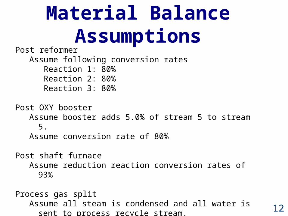
Material Balance Assumptions
Post reformerAssume following conversion rates
Reaction 1: 80%Reaction 2: 80%Reaction 3: 80%
Post OXY boosterAssume booster adds 5.0% of stream 5 to stream 5.Assume conversion rate of 80%
Post shaft furnaceAssume reduction reaction conversion rates of 93%
Process gas splitAssume all steam is condensed and all water is sent to process recycle
stream.Assume 60:40 split for streams 9:17.

13
Material Balance Assumptions (2)
Post CO2 removalAssume 100% removal of appreciable CO2.
Top gas to combustion splitAssume no water in this stream.
Ore feedAssume only Fe2O3.In reality this stream will contain, in addition to Fe2O3, Fe3O4, and
SiO2.Needs to be corrected to include other components.
Product streamAssume only pure Fe and residual Fe2O3.
Post reformer combustion
Assume total combustion of fuel gases from stream 21.
14
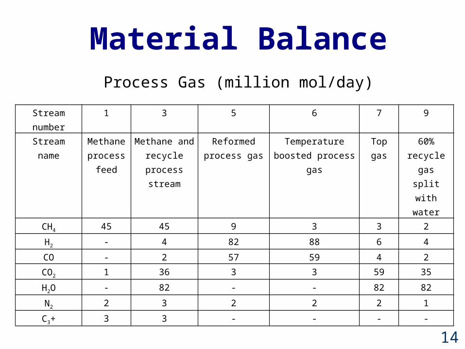
Material Balance
Stream number
1 3 5 6 7 9
Stream name Methane process
feed
Methane and recycle process stream
Reformed process gas
Temperature boosted process
gas
Top gas
60% recycle gas
split with water
CH4 45 45 9 3 3 2
H2 - 4 82 88 6 4
CO - 2 57 59 4 2
CO2 1 36 3 3 59 35
H2O - 82 - - 82 82
N2 2 3 2 2 2 1
C3+ 3 3 - - - -
Process Gas (million mol/day)

15
Energy Balance AssumptionsFor the furnace temperature we used an average
value of 980F.
For the reformer we used a temperature of 1562F
Energy balance of furnace based only on incoming and outgoing iron due to weight of
iron being substantially higher than weight of incoming gases.

16
Energy Balance
Page 5-6: Process Flow Diagram (1)
Page 7-12: Material Balance
Page 13-15: Energy Balance
Page 16: Work in progress
Page 17-19: Economics
Page 20: Summary
Page 21: References
Page 23: Process Flow Diagram (2)
Heats of formation Heat capacity Empirical Constants
Components MW ∆Hf a b c d
CH4 16 -64075666.38 0.03431 0.00005469 3.66E-09 -1.10E-11
H2O 18 -207922613.9 0.03336 -0.00000688 7.60E-09 -3.59E-12
CO 28 -95038693.04 0.02895 0.00000411 3.55E-09 -2.22E-12
CO2 44 -338357695.6 0.03611 0.00004233 2.89E-08 7.46E-12
H2 2 0 0.02884 7.65E-08 3.29E-09 -8.70E-13
O2 32 0 0.0291 0.00001158 -6.08E-09 1.31E-12
T Cp/R A B D
Fe 1043 3.005 -0.111 6.11E-03 1.15E-05
Fe2O3 960 12.48 11.812 9.70E-03 -1.98E-05
17
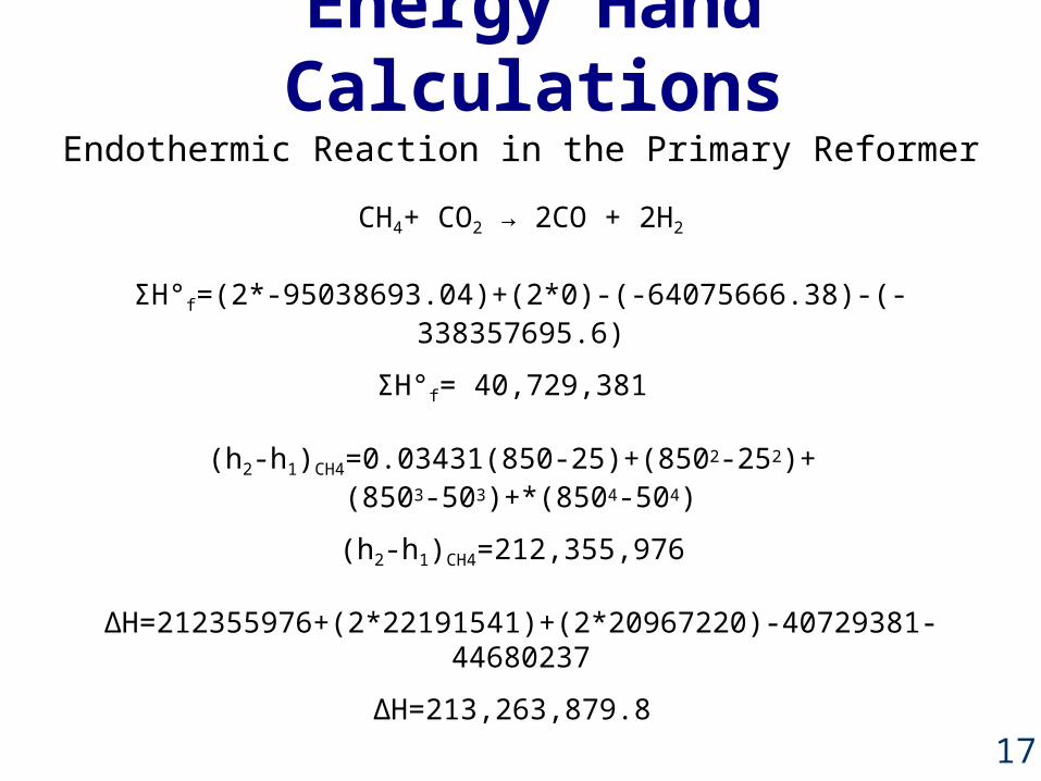
Energy Hand CalculationsEndothermic Reaction in the Primary Reformer
CH4+ CO2 → 2CO + 2H2
H°Σ f=(2*-95038693.04)+(2*0)-(-64075666.38)-(-338357695.6)
H°Σ f= 40,729,381
(h2-h1)CH4=0.03431(850-25)+(8502-252)+ (8503-503)+*(8504-504)
(h2-h1)CH4=212,355,976
∆H=212355976+(2*22191541)+(2*20967220)-40729381-44680237
∆H=213,263,879.8

18
Energy BalanceSUMMARY
REFORMERΔHCH4+ CO2 → 2CO + 2H2 213,000,000 38,000
CH4+ H2O → CO + 3H2 198,000,000 36,000
2CH4+ O2 → 2CO + 4H2 510,000,000 93,000
CO + H2O → CO2 + H2 -14,000,000 -2,700
CH4→ C(S) + 2H2 65,000,000 12,000
OXY BOOST
2CH4+ O2 → 2CO + 4H2 510,000,000 93,000
2CH4+ 2O2 → CO2 + 2H2O -170,000,000 -31,000
FURNACE
Fe2O3 + 3CO → 2Fe + 3CO2
Hreaction =-1.08743E+12[KJ]Fe2O3 + 3H2 → 2Fe + 3H2O
19
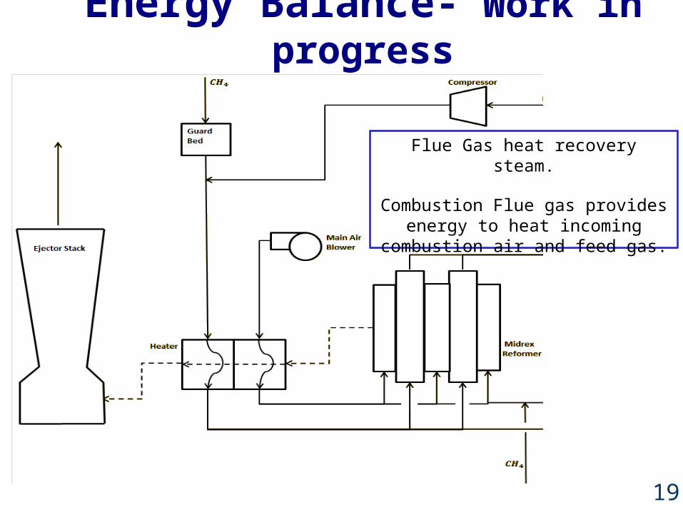
Energy Balance- Work in progress
Flue Gas heat recovery steam.
Combustion Flue gas provides energy to heat incoming combustion air and feed
gas.
20
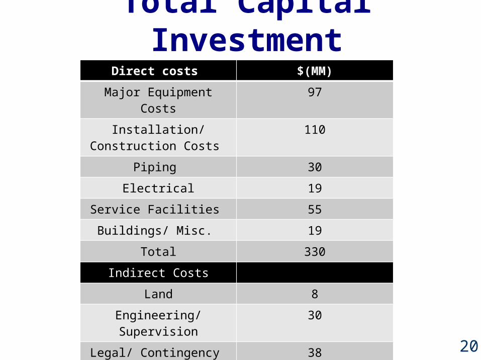
Total Capital Investment
Page 5-6: Process Flow Diagram (1)
Page 7-12: Material Balance
Page 13-15: Energy Balance
Page 16: Work in progress
Page 17-19: Economics
Page 20: Summary
Page 21: References
Page 23: Process Flow Diagram (2)
Direct costs $(MM)
Major Equipment Costs 97
Installation/ Construction Costs
110
Piping 30
Electrical 19
Service Facilities 55
Buildings/ Misc. 19
Total 330
Indirect Costs
Land 8
Engineering/ Supervision 30
Legal/ Contingency 38
Total 76
Total Capital Investment 406

21
Major Equipment CostMajor Equipment Costs $(MM)
Reformer 35
Shaft Furnace 32
Other Equipment 30
Total 97

22
ProfitProduction (Tons/yr) 2,000,000
Production Cost ($/ton) 240
Product Sell Price ($/ton) 425
Profit per ton ($/ton) 185
Total Profit per Year ($) 370,000,000

23
Summary1. This process will produce 2.2 million tons DRI.
2. This plant will consume roughly 210,000 MW-h annually .
3. 23 million mols of CO2 will be sent to the gas treatment plant.
4. Based on our economic analysis, this plant will cost approximately $97 million.
24
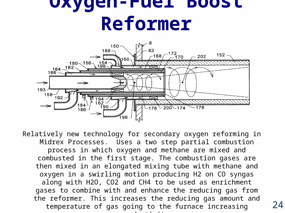
Oxygen-Fuel Boost Reformer
Relatively new technology for secondary oxygen reforming in Midrex Processes. Uses a two step partial combustion process in which oxygen and methane are mixed and combusted in the first stage. The combustion
gases are then mixed in an elongated mixing tube with methane and oxygen in a swirling motion producing H2 on CO syngas along with H2O, CO2 and
CH4 to be used as enrichment gases to combine with and enhance the reducing gas from the reformer. This increases the reducing gas amount and
temperature of gas going to the furnace increasing productivity.

25
References1. http://www.midrex.com/uploads/documents/
MIDREXShaftBrochure2.pdf2. http://www.midrex.com/uploads/documents/
MidrexCorporateBrochure1.pdf3. US patent # 6602317 b24. US patent # 6524356 b25. US patent # 6506230 b26. http://www./handler.cfm/cat_id/163/section/global7. http://www.midrex.com/uploads/documents/SSS.pdf8. http://www.midrex.com/uploads/documents/DFM1Q041.pdf9. http://www.midrex.com/uploads/documents/New
%20Developments%20in%20the%20Midrex%20DR%20Process.pdf

26
Questions

27
Complete Flow Diagram
Oxy Fuel Boost Reformer
Removal
GuardBed
Heater
Shaft Furnace
Top Gas Scrubber
Midrex Reformer
Main Air Ejector Stack
Iron Ore
Iron Briquettes
Compressor
Fuel Gas
Recycle1.
2.
3.
4.
5.
6.
7.
9.10.
11.
12. 21.
14.
15.
16.
17.
18.
19.
20.
13.
22.
23.
24.
8.

28
Stream Names 1 2 3 4 5 6 7 8 9 10 11 Methane process feedDesulfurized methane to processMethane and recycle process streamHeated process gasReformed process gasTemperature boosted process gasTop gas Scrubbed top gas60% recycle gas split with waterCompressed recycle gasAir to combustion
Fe2O3 million mols/day - - - - - - - - - - - Fe - - - - - - - - - - - CH4 45 45 47 47 9 3 3 3 2 2 - H2 - - 4 4 82 88 6 6 4 4 - CO - - 2 2 57 59 4 4 2 2 - CO2 1 1 36 36 3 3 59 59 35 35 - H2O - - 82 82 - - 82 82 82 82 - N2 2 2 3 3 2 2 2 2 1 1 334
H2S - - - - - - - - - - - C - - - - - - - - - - - o2 - - - - - - - - - - 94 C3+ 3 3 3 3 - - - - - - - Total flow 50 50 176 176 154 155 155 155 126 126 428
12 13 14 15 16 17 18 19 20 21 22 23 24 Heated air to combustionFuel gas to combustionMethane to combustionOxygen to OXY fuel boosterMethane to OXY fuel booster40% top gas split to combustionCO2 removalOre feed DRI productMixed streams to combustionCombustion productsCooled exhaust productsExhaust
- - - - - - - 98 7 - - - - - - - - - - - - 182 - - - - - 1 45 - 3 1 - - - 46 - - - - 2 - - - 2 - - - 2 - - - - 2 - - - 2 - - - 2 - - - - - 1 - 0 23 23 - - 1 48 48 48 - - - - - - - - - - 92 92 92
334 1 2 - 0 1 - - - 337 337 337 337
- - - - - - - - - - - - - - - - - - - - - - - - - -
94 - - 2 - - - - - 94 - - - - - 3 - 0 - - - 3 - - -
428 6 50 2 4 30 23 98 189 484 477 477 477