Embed Size (px)
Citation preview
batan
Seminar Pendayagunaan Teknologi Nuklir 2017Badan Tenaga Nuklir Nasional
Tangerang Selatan 21-23 November 20Ii
RADIOGRAPH OF SOFT METALLIC CASTINGUSING COMPUTED RADIOGRAPHY
~SENPATIN
Sugiharto1*, Yushar Kriswandono2, Wibisono1, Kushartono1, Harun AI RasyidRamadhany1, Djoli Soembogo1, NamadSianta and Sigit Budi Santoso1
I) Center for Application of Isotopes and Radiation Application, JI. Lebak Bull/s Raya No. ./9 Jakarta,Indonesia 12././0.
2) Sepllluh NopemberInstitute ofTeknologi. Kampl/s ITS Slikolilo, Slirabaya, Indonesia, 60111.
ABSTRACT
Radiograph of soft metallic casting using computed tomography. BA TAN has long timeemployed conventional radiography modality using film-screen (F/S) for examination ofdiscontinuities or flaws in metallic materials produced from welding, casting and forging. Thestandard examinations used were based established international standards such as ASTM orASME. In order to increase capacity building, capability and demanding on digital technology,BATAN's NOT laboratory has recently been equipped with new variant of digital radiographyequipment namely computed radiography set. As a newcomer in industrial NOT's world, theestablished examination standards of computed radiography were very limited and were notaccepted worldwide yet. Only several advanced countries were used this technology. In this study,radiographs generated using computed radiography was compared with conventional film-screenradiography. A soft metallic casting test piece has been exposed using X-ray generated from themachine. Expose preparation was based on ASTM standard for radiographic examination ofmetallic casting. Source to film distance (sfd) was determined based on maximum projection ofunsharpness geometry of the test piece. Exposed time was determined based on existing exposurechart for the X-ray energy of 130 kV and current of 5 mA. The placements of IQI and material'smarking were prepared for source side exposure. The image density and image sensitivity inradiograph, as a measure of the image quality, were analyzed both conventionally and digitally.Based on examination, the conventional film-screen radiograph revealed better image qualitycompared to those of digital radiograph. It was understood that the exposure preparation wasbased on the established standards for conventional film-screen radiography.
Keywords: conventional radiography, film-screen, compl/ted radiography, soft metallic casting.
ABSTRAK
BATAN telah lama menggunakan modalitas radiografi konvensional film-skrin (F/S) untukmendeteksi cacat-cacat atau diskontinuitas yang ada di dalam material logam hasil pengelasan,pengecoran dan penempaan. Standar pengujian yang digunakan didasarkan pada standarinternasional yang ada seperti ASTM atau ASME. Untuk meningkatkan kapasitas, kemampuan danpermintaan tekonolgi digital, laboratorium investigasi tak rusak dan diagnosis BA TAN baru-baru inidilengkapi dengan varian baru perangkat radiografi digital yaitu computed radiografi. Sebagaivarian pendatang baru di dalam dunia NOT, standar pengujian untuk computed radiografi sangatterbatas dan belum dapat diterima di seluruh'dunia:- Hanya -beb'eraps Negara' maju yang telah- 0 ,_._uo 0
menggunakan teknologi ini. Oalam makalah ini, radiograf yang dihasilkan dari computed radiografidibandingkan dengan radiograf yang dihasilkan dari radiografi konvensional film-skrin. Benda ujiberupa logam lunak telah disinari menggunakan sinar-X. Persiapan penyinaran dilakukanberdasarkan standar ASTM untuk pengujian radiografi coran logam. Jarak antara sumber dan film(sfd) ditentukan berdasarkan proyeksi maksimum dari ketidaktajaman geometri benda uji. Waktupenyinaran ditentukan berdasarkan grafik paparan sinar-X untuk energy 130 kV dan arus 5 mA.Penempatan IQI dan material penanda didasarkan pada penyinaran arah sumber. Oensitasbayangan dan sensitivitas bayangan radiograf, sebagai ukuran kualitas bayangan dianalisis secarakonvensional dan secara digital. Berdasarkan hasil pengujian, radiografi konvensional film-skrin
184 Sugiharto, dkk.
batao
Seminar Pendayagunaan Teknologi Nuldir 2017Badan Tenaga Nuklir Nasional
Tangerang Selatan 21-23 November 2017
f'~'.'(Yk. ~4?".>"',~_ ,-,,0<-°0- -~' , , "~;%W- --,<~,
<', .... , ?SENPAHN
memperlihatkan kualitas bayangan yang lebih baik dibandingkan dengan yang dihasilkan dariradiografi digital. Hasil ini dapat dimengerti karena penyinaran didasarkan pada standar yang adauntuk radiografi konvensional film-skrin.
Kata kunci : radiografi konvensional, film-skrin, computed radiografi, coran logam lunak
INTRODUCTION
Shortly after invention of X-ray by Roentgenin 1895, he was able to show a radiographof left hand of his wife, Martha, on
photographic film [1]. Since then, various X-raysmachines were produced and manufactured fordiagnose and treatment purposes in medicinethrough radiographic examination [2]. Invention ofradioactivity by Becquerel in 1896, followed bycapability of nuclear reactor in producing gammarays sources, especially Co-60, was open newera of imaging to complement of X-ray invention[3]. X-rays and gamma rays are alwaysassociated with high energy photon of shortwavelength which capable of penetratingmaterials they are passing through. X-rays aregenerated by bombarding high-atomic numbermetallic target, usually tungsten, with high kineticenergy of electron in X-ray tube. The gammarays, however, are produced by disintegratingprocesses of unstable nuclei [4]. X-rays aremostly used in nuclear medicine, whereasgamma rays are used in industry [3,5].
In conventional methods, image isproduced on recording media such as film-screen(F/S) materials. The classical examples of theseimaging modalities are photography andradiography. In modern society, however, imagesare produced electronically and it appearanceespecially after advent of computer technology inthe 1960s [6,7]. The first form of digital imagingwas angiography which was introduced in 1977and put to clinical use in 1980. Today, the term ofdigital radiography comprises computedradiography (CR) and digital direct radiography(DDR). CR is radiographic system that replacedfilm-screen (F/S) in conventional radiography withstorage phosphor plate as the image receptor. Inpractical society the term storage phosphor plate
- is--interchangeable with. image plate. (IP). Thelatent image on the exposed IP is scanned by alaser beam and converted into digital data toproduce an image. The storage phosphor imageplates of CR were first used to record generalradiograph in 1980. DDR, on the other hand,acquire image data in digital format without laserscanning to extract the latent image. DDR usingcharged-coupled device (CCD) was introduced in1990 for producing digital image from directcapturing X - ray [8-16]
Sugiharto, dkk.
BATAN has long used conventional filmscreen (F/S) technique for radiographicexamination. New investment by establishment ofcomputed radiography (CR) equipment is to fulfilldemand on digital radiography for materialstesting which offering fast and more economicservices [17,18]. The purpose of this currentstudy is therefore to demonstrate of producing aradiograph using image modalities ofconventional and computed radiography. The testobject is a motorbike key house made of softmetallic casting material. The set upmeasurement of parameters are based on ASTMstandards for radiographic examination [19,20].Two modes of image processing were carried outmanually and using CR reader. Thediscontinuities or defect in the test object wereexamined by observing the correspondingradiographs
THEORY
The underlying theory of radiography isrelated to absorption of photon by material. Asphoton has no charge, the absorption of photon iscommonly termed as attenuation of photon. Theattenuation is contributed from three modeprocesses of interactions: photoelectric, Comptonscattering and pair production. In photoelectricmode, the incident X-ray photon is completelyabsorbed by an inner shell electron which is thenejected from the atom as photoelectron. InCompton effect, the energy of the incident photonis partially absorbed by an outer shell electron,which is then ejected from the atom as a recoilelectron. The remaining photon is reemitted as aCompton scatter photon which may penetrate toreach the image receptor. Pair production canonly be occurred when the photon energy is atleast 1,02 MeV. In pair production high energyphoton travelling close ..to the nucleus of high-atomic number is converted into a pair ofparticles: an electron and a positron.
The total attenuation coefficient per atom,(J, is expressed as [21]
(J = (Jpe + (Jcs + (Jpp (1)Where (Jpe , (Jcs and (Jpp are respectivelyabsorption coefficient for photoelectric, Comptonscattering and pair production interaction peratom. If there are any other modes of interaction
185
batan
Seminar Pendayagunaan Teknologi Nuklir 2017Badan Tenaga Nuklir Nasional
Tangerang Selatan 21-23 November 2017~
SENPATEN
The purpose in radiography is formaterial examination through analysis of imageon radiograph. In this study, two methods aredescribed, each for conventional film-screen(F/S) radiography and computed radiography(CR). Conventional (F/S) radiographic consists oftransparent, bluish plastic substrate coated onboth sides with an emulsion of radiation sensitivesilver halide crystal such as silver bromide andsilver chloride in micro size. When incident Xrays or gamma rays or light rays strike theemulsion crystal or grain, some of bromide ion,Br are liberated and captured by the silver ion,Ag+. In such situation, the radiograph contains alatent image because the changes in the grainsare virtually undetectable. The exposed grainsare more sensitive to react with the developingsolution. When the film is processed in darkroom, the exposed film will react with solution todevelop latent image on radiograph.
Film processing basically involves fivesteps, as follows [21-23]: (1) development oflatent image by developing solution. Electrons indeveloping solution convert the silver halide grainto metallic silver in the exposed film. To obtain anoptimum result, the temperature of thedeveloping solution should properly be controlled,
(2) stopping development of latent image. bydiluting and washing the remnant of developingsolution away with water in stop bath, (3) fixingthe latent image using fixing solution. Unexposed
silver halide crystals ~re remove~ by the .fixing The experiment was carried out bybath and leaving the silver metalli~ cryst~1 I~ the exposing key-house of motorbike made of soft
.radiograph. In this stage_the late~t Image IS. flxed. -.metallic casting 'materials of the thickness 18 mm(4) washing the radiograph.contame~ fixed Image using X _ rays beam generated from the X - rayby removal all the processmg chemlc~ls, a~d (~) machine. The amperage and electrical voltage ofdrying the film for viewing. Processmg film IS the machine were set at 5 mA and 130 kVgoverned by rigid rules in .the sense that the respectively. The source to film distance (sfd)quality of the film on the radiograph dep~nds on was set at 1 m. The image quality indicator (101)chemical concentration, temperature, time of used was wire type101S016. For conventionalprocessing and physical movement [22] F/S radiography, the medium speed of Agfa 07
Image f?rm~ti?n for . computed radiographic film of the size 4 inch x 10 inc~ wasradiography (CR) m digital format differs from used as recording media to record a latent Imageconventional F/S radiography. CR system use that become visible after chemical processing.image plate (IP) having a detective layer of
they will contribute to total attenuation coefficient.The incident photon when passing through amaterial of thickness x is expressed as [21,22]
(2)
where I is transmitted intensity of photon, 10 isintensity of incident photon, n is number of atomsper cubic centimeter, (5 is total atomic crosssection (cm2) per atom and x is thickness ofmaterial.
METODOLOGI
186
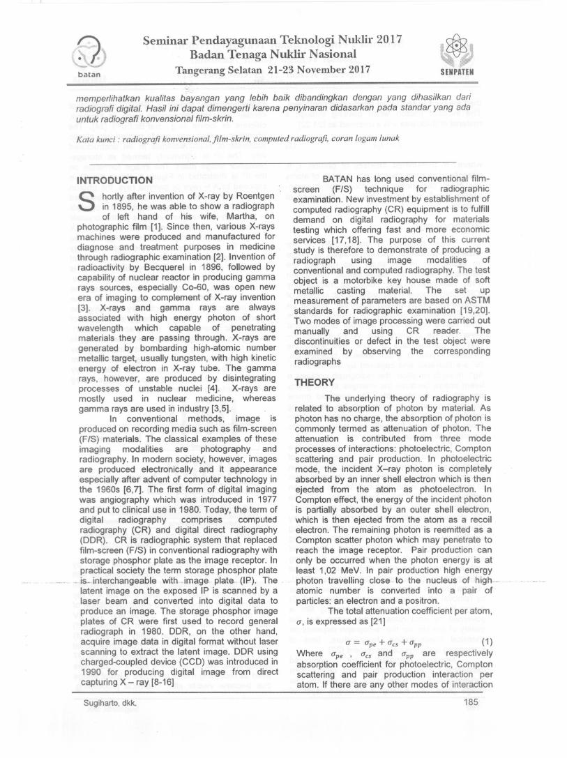
photostimulable phosphor (PSP) crystal thatcontain different halogenides such as bromine,chlorine or iodine (e.g., BaFBr:Eu2+) [24]. Thephosphor crystals are usually coated into plasticsubstrate of resin materials in an unstructuredway. The IP is commonly termed as storagephosphor image plate. The image formation onthe IP is illustrated in Figure 1. When the IP isexposed to X - rays or gamma rays, the photonenergy of X - rays or gamma rays is absorbedand temporarily stored by the phosphor crystalsin the manner that the electrons of the crystalsare excited to higher energy levels. In this way, X- rays or gamma rays photon energy can bestored for several hours in the higher energylevel, depending on the specific physicalproperties of the phosphor crystals [8]. If it isdone, the stored energy will decrease over time.It is therefore, the readout process should bestarted immediately after exposure the IP. Theread out process is conducted by scanning theexposed crystal using high energy laser beam ofa specific wavelength (flying-spot scanner).During the scanning process, the stored energy isset to free returning to the ground state energy byemitting light having a wavelength different fromthe laser beam. These lights are collected byphotodiode and converted into an image usingAID converter for further analysis.
Ii IX,RAYS
Stcroge I:i I~ energy
(o_le. 10
rtIo1omullipll~ AlD-CoIIveIler I...~~~~.~~.._..._.._Figure 1. Illustrationof digital image formationon
storage phosphor imageplate of CR [8]
Sugiharto,dkk.
batan
Seminar Pendayagunaan Telmologi Nuklir 2017Badan Tenaga Nuklir Nasional
Tangerang Selatan 21-23 November 2017
The film was sandwiched by pair of intensifyingscreens of the thickness 0.125 mm each. For CR,the recording media used was storage phosphorimage plate (IP) and the latent image isprocessed by CR reader [25]. The detailexposure parametersare shown in Table. 1.
Table 1. Exposure parameters of the radiographicexperiment
Imaging modalitiesCRSoft metal18mm5 mA, 130 kV
Parameters
MaterialThicknessAmperage,voltageFilm speedIntensifyingscreensfd101
Exposure timeProcessing:DeveloperStop bathFixer
Washing
F/S
Soft metal18 mm5 mA, 130 kV
Medium,Agfa D70.125 mm
1mDIN101S01590 s
5 minutes7 minutes15 minutes20 minutes
IIP, blue typeI .
1 mDIN10lS01550 s, 90 s
CR reader
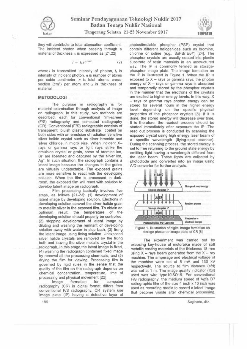
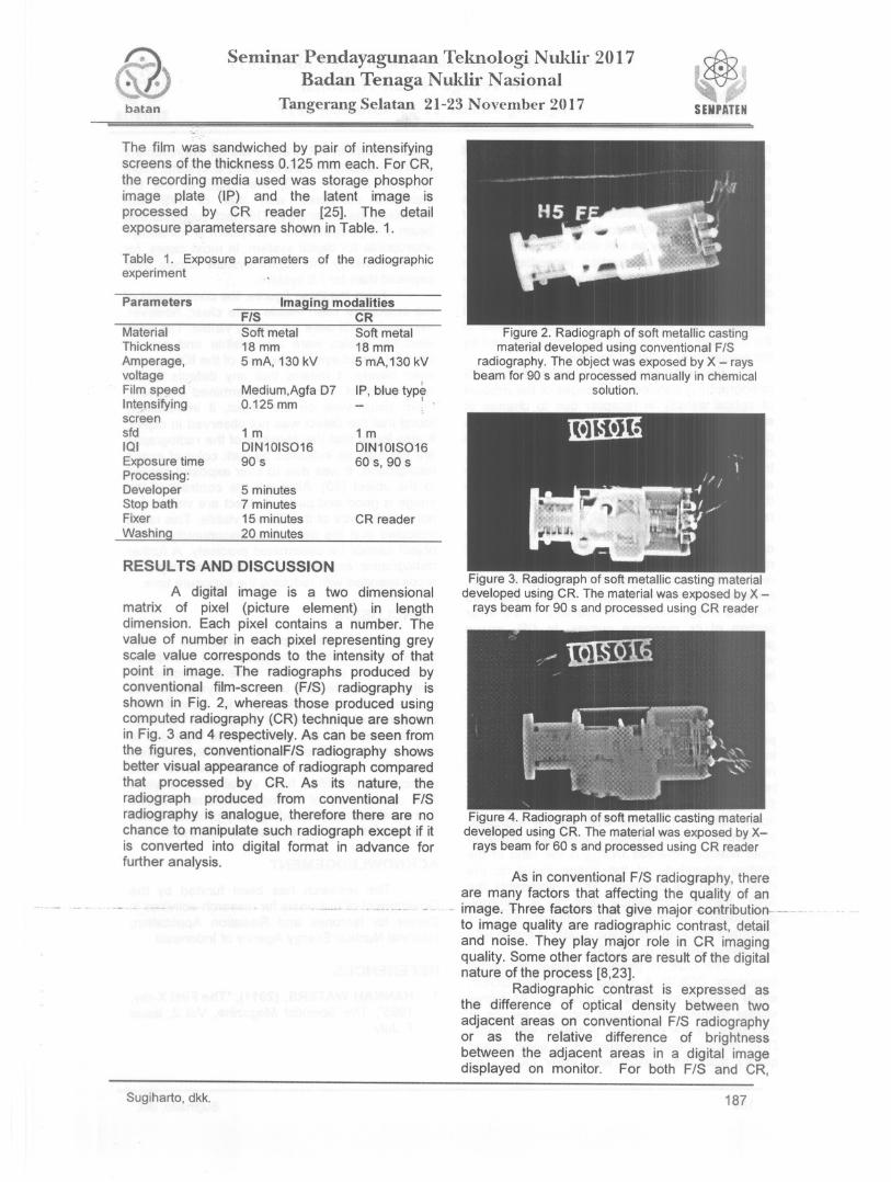
Figure 2. Radiograph of soft metallic castingmaterial developed using conventional F/S
radiography. The object was exposed by X - raysbeam for 90 s and processed manually in chemical
solution.
RESULTS AND DISCUSSION
A digital image is a two dimensionalmatrix of pixel (picture element) in lengthdimension. Each pixel contains a number. Thevalue of number in each pixel representing greyscale value corresponds to the intensity of thatpoint in image. The radiographs produced byconventional film-screen (F/S) radiography isshown in Fig. 2, whereas those produced usingcomputed radiography (CR) technique are shownin Fig. 3 and 4 respectively. As can be seen fromthe figures, conventionalF/S radiography showsbetter visual appearance of radiograph comparedthat processed by CR. As its nature, theradiograph produced from conventional F/Sradiography is analogue, therefore there are nochance to manipulate such radiograph except if itis converted into digital format in advance forfurther analysis.
Sugiharto, dkk.
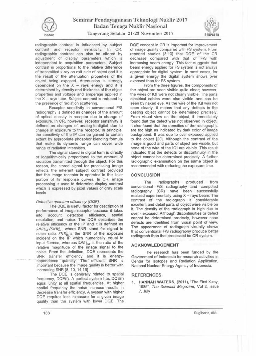
Figure 3. Radiograph of soft metallic casting materialdeveloped using CR. The material was exposed by X
rays beam for 90 s and processed using CR reader
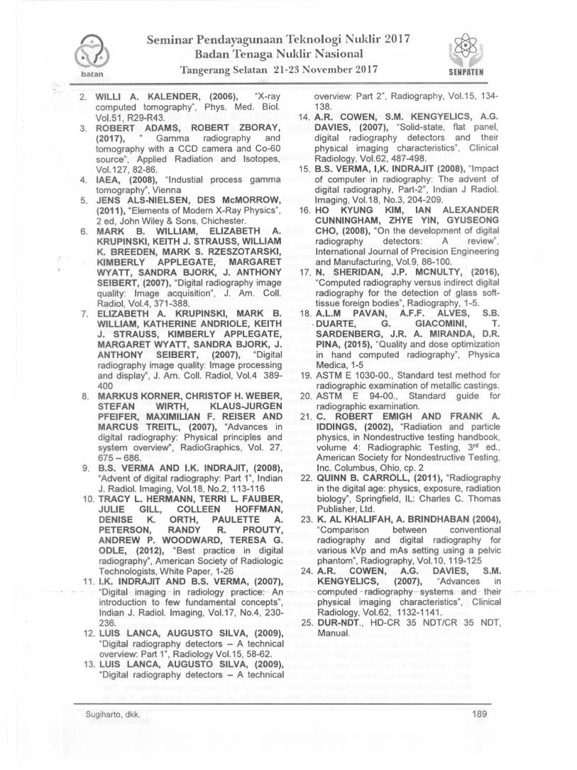
Figure 4. Radiograph of soft metallic casting materialdeveloped using CR. The material was exposed by X
rays beam for 50 s and processed using CR reader
As in conventional F/S radiography, thereare many factors that affecting the quality of an
. - image. Three factors that give majorcontribution---to image quality are radiographic contrast, detailand noise. They play major role in CR imagingquality. Some other factors are result of the digitalnature of the process [8,23].
Radiographic contrast is expressed asthe difference of optical density between twoadjacent areas on conventional F/S radiographyor as the relative difference of brightnessbetween the adjacent areas in a digital imagedisplayed on monitor. For both F/S and CR,
187
batan
Seminar Pendayagunaan Teknologi Nuklir 2017Badan Tenaga Nuklir Nasional
Tangerang Selatan 21-23 November 2017~SENPATEN
radiographic contrast is influenced by subjectcontrast and receptor sensitivity. In CR,radiographic contrast can also be altered byadjustment of display parameters which isindependent to acquisition parameters. Subjectcontrast is proportional to the relative differenceof transmitted x-rayon exit side of object and it isthe result of the attenuation properties of theobject being exposed. Attenuation is stronglydependent on the X - rays energy and it isdetermined by density and thickness of the objectproperties and voltage and amperage applied inthe X - rays tube. Subject contrast is reduced bythe presence of radiation scattering.
Receptor sensitivity in conventional F/S
radiography is defined as changes of the amountof optical density in receptor due to change ofexposure. In CR, however, receptor sensitivity isdefined as changes of analog-to-digital due tochange in exposure to the receptor. In principle,the sensitivity of the IP can be gained to certainextent by appropriate phosphor blending formulathat make its dynamic range can cover widerange of radiation intensities.
The signal stored in digital form is directlyor logarithmically proportional to the amount ofradiation transmitted through the object. For thisreason, the stored signal for processing imagereflects the inherent subject contrast providedthat the image receptor is operated in the linierportion of its response curves. In CR, imageprocessing is used to determine display contrastwhich is expressed by pixel values or gray scalelevels.
Detective quantum efficiency (DQE).The DQE is useful factor for description of
performance of image receptor because it takesinto account detection efficiency, spatialresolution, and noise. The DQE describes therelative efficiency of the IP and it is defined asSNR~ut!SNRfn' where SNR stand for signal tonoise ratio. SN Rfn is the SNR of the exposureincident on the IP which numerically equal toinput fluence, whereas SNR~ut is the ratio of therelative magnitude of the image signal to thenoise. From the definition, DQE represents theSNR transfer efficiency and it is energydependence' quantity~' Tne - effiCient -- SNR isimportant because the image quality is better withincreasing SNR [8, 10, 14,16]
The DQE is generally related to spatialfrequency, DQE(f). A perfect system has DQE(f)equal unity at all spatial frequencies. At higherspatial frequency the noise increase results indecrease transfer efficiency. A system with higherDQE requires less exposure for a given imagequality than the system with lower DQE. The
188
DQE concept in CR is important for improvementof image quality compared with FS system. Fromreported studies [8,10] that DQE of the CRdecrease compared with that of F/S withincreasing beam energy. This fact suggests thatbeam energy applied for FS system is not alwaysappropriate for digital system. In most cases, fora given energy the digital system shows overexposed than for FS system.
From the three figures, the components ofthe object are seen visible quite clear; however,the wires of IQI were not clearly visible. The partselectrical cables were also visible and can beseen by naked eye. As the wire of the IQI was notseen clearly, it means that any defects in thecasting object cannot be determined precisely.From visual view on the object, it immediatelyfound that the defect was not observed in object.It also found that the densities of the radiographsare too high as indicated by dark color of imagebackground. It was due to over exposed appliedto the object [20]. Although the contrast of theimage is good and parts of object are visible, butnone of the wire of the IQI are visible. This resultindicated that the defects or discontinuity in theobject cannot be determined precisely. A furtherradiographic examination on the same object isrecommended with reducing the exposure time.
CONCLUSION
The radiographs produced fromconventional F/S radiography and computedradiography (CR) have been successfullyrealized experimentally using X - rays beam. Thecontrast of the radiograph is considerableexcellent and detail parts of object were visible onit. The density of the radiograph is high due toover - exposed. Although discontinuities or defectcannot be determined precisely, however nonedefects are identified from visual point of view.The appearance of radiograph visually showsthat conventional F/S radiography produce betterradiograph than that processed be CR system.
ACKNOWLEDGEMENT
The research has been funded by theGovernment of Indonesia for research activities in
"'Center for' Isotopes' an'Cf'Radiation'Ap'plication,National Nuclear Energy Agency of Indonesia.
REFERENCES
1. HANNAH WATERS, (2011), "The First X-ray,1985", The Scientist Magazine, Vol 2, issue7, July
Sugiharto, dkk.
Seminar Pendayagunaan Teknologi Nuklir 2017Badan Tenaga Nuklir Nasional
batan Tangerang Selatan 21-23 November 2017
2. WILLI A. KALENDER, (2006), "X-raycomputed tomography", Phys. Med. BioI.Vol.51 , R29-R43.
3. ROBERT ADAMS, ROBERT ZBORA Y,(2017), " Gamma radiography andtomography with a CCD camera and Co-60source", Applied Radiation and Isotopes,VoI.127,82-86.
4. IAEA, (2008), "Industial process gammatomography", Vienna
5. JENS ALS-NIELSEN, DES McMORROW,(2011), "Elements of Modern X-Ray Physics",2 ed, John Wiley & Sons, Chichester.
6. MARK B. WILLIAM, ELIZABETH A.KRUPINSKI, KEITH J. STRAUSS, WILLIAMK. BREEDEN, MARK S. RZESZOT ARSKI,KIMBERLY APPLEGATE, MARGARETWYATT, SANDRA BJORK, J. ANTHONYSEIBERT, (2007), "Digital radiography imagequality: Image acquisition", J. Am. Coil.Radiol, VolA, 371-388.
7. ELIZABETH A. KRUPINSKI, MARK B.WILLIAM, KATHERINE ANDRIOLE, KEITHJ. STRAUSS, KIMBERLY APPLEGATE,MARGARET WYATT, SANDRA BJORK, J.ANTHONY SEIBERT, (2007), "Digitalradiography image quality: Image processingand display", J. Am. Coil. Radiol, VolA 389400
8. MARKUS KORNER, CHRISTOF H. WEBER,STEFAN WIRTH, KLAUS-JURGENPFEIFER, MAXIMILIAN F. REISER ANDMARCUS TREITL, (2007), "Advances indigital radiography: Physical principles andsystem overview", RadioGraphies, Vol. 27,675 - 686.
9. B.S. VERMA AND I.K. INDRAJIT, (2008),"Advent of digital radiography: Part 1", IndianJ. Radiol.lmaging, Vo1.18, No.2, 113-116
10. TRACY L. HERMANN, TERRI L. FAUBER,JULIE GILL, COLLEEN HOFFMAN,DENISE K. ORTH, PAULETTE A.PETERSON, RANDY R. PROUTY,ANDREW P. WOODWARD, TERESA G.ODLE, (2012), "Best practice in digitalradiography", American Society of RadiologicTechnologists, White Paper, 1-26
11. I.K. INDRAJIT AND B.S. VERMA, (2007),"Digital- imaging' in radiologypractice:-' An -introduction to few fundamental concepts",Indian J. Radiol. Imaging, Vo1.17, NoA, 230236.
12. LUIS LANCA, AUGUSTO SILVA, (2009),"Digital radiography detectors - A technicaloverview: Part 1", Radiology Vo1.15, 58-62.
13. LUIS LANCA, AUGUSTO SILVA, (2009),"Digital radiography detectors - A technical
Sugiharto, dkk.
overview: Part 2", Radiography, Vo1.15, 134138.
14. A.R. COWEN, S.M. KENGYELlCS, A.G.DAVIES, (2007), "Solid-state, flat panel,digital radiography detectors and theirphysical imaging characteristics", ClinicalRadiology, Vo\.62, 487-498.
15. B.S. VERMA, I,K. INDRAJIT (2008), "Impactof computer in radiography: The advent ofdigital radiography, Part-2", Indian J Radiol.Imaging, Vo1.18, No.3, 204-209.
16. HO KYUNG KIM, IAN ALEXANDERCUNNINGHAM, ZHYE YIN, GYUSEONGCHO, (2008), "On the development of digitalradiography detectors: A review",International Journal of Precision Engineeringand Manufacturing, Vo1.9, 86-100.
17. N. SHERIDAN, J.P. MCNULTY, (2016),"Computed radiography versus indirect digitalradiography for the detection of glass softtissue foreign bodies", Radiography, 1-5.
18. A.L.M PAVAN, A.F.F. ALVES, S.B.. . DUARTE, G. GIACOMINI, T.
SARDENBERG, J.R. A. MIRANDA, D.R.PINA, (2015), "Quality and dose optimizationin hand computed radiography", PhysicaMedica, 1-5
19. ASTM E 1030-00., Standard test method forradiographic examination of metallic castings.
20. ASTM E 94-00., Standard guide forradiographic examination.
21. C. ROBERT EMIGH AND FRANK A.IDDINGS, (2002), "Radiation and particlephysics, in Nondestructive testing handbook,volume 4: Radiographic Testing, 3rd ed.,American Society for Nondestructive Testing,Inc. Columbus, Ohio, cpo2
22. QUINN B. CARROLL, (2011), "Radiographyin the digital age: physics, exposure, radiationbiology", Springfield, IL: Charles C. ThomasPublisher, Ltd.
23. K. AL KHALIFAH, A. BRINDHABAN (2004),"Comparison between conventionalradiography and digital radiography forvarious kVp and mAs setting using a pelvicphantom", Radiography, Vo1.10, 119-125
24. A.R. COWEN, A.G. DAVIES, S.M.KENGYELlCS, (2007), "Advances in
-computed - radiography" systems and- theirphysical imaging characteristics", ClinicalRadiology, Vo1.62, 1132-1141.
25. DUR-NDT., HD-CR 35 NDTtCR 35 NDT,Manual.
189