Embed Size (px)
Citation preview

1
Coastal Shoreline Defense StructuresBy Thomas Barnard
ObjectivesThe purpose of this self-taught education unit is to acquaint the reader with the various types of shoreline
defense structures which are employed in the Chesapeake Bay region and the U.S. in general. There are moreerosion control measures than those explained here but these are the most generally used and accepted withinthe marine community. Each structure will be defined and its use along the shoreline will be described. Generaldesign and location considerations will be discussed as well as the general definitions and terminology neces-sary for each type of structure.
Following completion of this study unit, the reader will be generally acquainted with:1. Shoreline erosion and its causes;2. The types of structures most often employed to address shoreline erosion;3. General design considerations for each shoreline structure;4. Specific definitions and terminology for each structure.
IntroductionAt the present time the Chesapeake Bay and most areas of the east and gulf coasts are experiencing varying
degrees of relative sea level rise. This is defined as the net change in water elevation due to the combinedinfluence of local land movement (subsidence) and the absolute change in water level. The primary result of sealevel rise is shoreline retreat (erosion) along with other secondary shoreline changes.
Chesapeake Bay sea level rise is approximately one foot per century at present. There is some evidencethat sea level rise is accelerating due to global climate change. This factor has not been completely documentedhowever, primarily due to the difficulty involved with modelling weather and climate features on a global scaleand determining long term trends in the absence of adequate data.
Erosion or shoreline retreat may be caused on a local scale by differences in erodibility of soils, watercurrents, boat wakes etc. Any of these local features, sea level rise or a combination of any and all may be thereason a structure is employed along a particular reach of shoreline. It may also be present for purely landscapeand/or aesthetic reasons.
The remainder of this educational unit will characterize and describe the following shoreline erosiondefense structure types:
1. bulkheads2. riprap3. marsh toe protection4. breakwaters5. groins and jetties6. vegetative control
Self-Taught Education Unit

2
BulkheadsA bulkhead (Figure 1) is a
vertical wall generally aligned parallelto the shoreline and designed to retaingranular backfill material (soil, sand)and to prevent wave-induced erosion.(Figures 2, 3, 4, 5) Bulkheads areusually constructed of chemicallytreated wood with galvanized fixtures.Bulkheads are also constructed ofconcrete, asbestos plates, steel, alumi-num and most recently from recycledplastics. Asbestos is no longer usedand the new recycled products arepresently being tested in a variety ofsituations.
In general, a bulkhead is con-structed of round pilings which aredriven (by pile drivers) or jetted (bywater pressure) into the bottom.(Figures 6, 7) Vertical tongue-and-
Figure 1. Typical bulkhead cross section. (From Dept. of Conserva-tion and Recreation, Shoreline Programs Office)
Figure 2. Bulkhead (typical). Figure 3. Oceanfront bulkhead.
Figure 4. Aluminum bulkhead. Figure 5. Design criteria are important!

3
groove sheeting forms the “wall” and goes into the bottom in the same manner. The structure should be drivenor jetted to a depth at least equal to the height of the structure above the mud line. (Figure 8) Whalers runhorizontally between the pilings and brace the sheeting. Tiebacks, usually galvanized steel rods, pass throughthe pilings and the wall adjacent to the bulkhead and aretied to anchor piles (wooden vertical posts, commonlycalled deadmen) which help to anchor the wall. (Figure9) Screw anchors may be employed in specific situa-tions where it is not feasible to use deadmen and tie-backs. Return walls are employed at the ends of thebulkhead in situations where it does not tie into anexisting structure protecting adjacent property. (Figure10) Return walls run back to the land, approximatelyperpendicular to the wall, and prevent the wall frombeing outflanked as erosion continues to occur onadjacent unprotected property. The landward side of theentire structure is generally faced with geotechnicalmaterial (filter cloth), a woven synthetic textile whichwhen placed between the wall and the backfill material,prevents the washout of soil while allowing water to
Figure 6. Installing sheet piles. Figure 7. Tie back rods.
Figure 8. Loss of backfill and eventual bulkheadfailure is the result of sheeting not driven to sufficientdepth.
Figure 9. Galvanized rod tie-backs.
Figure 10. Steel bulkhead (return wall).

4
pass. (Figure 11) This minimizes the build-up of ahydraulic head landward of the structure.
Bulkheads should be aligned landward of allwetlands and should be properly engineered for themarine environment. Riprap, placed along the seawardtoe of the bulkhead, may be necessary to prevent scourin front of the structure due to wave energy. A majorproblem of bulkheads is that they reflect most wavesstriking them. In many cases this results in passing the erosion problem along to the next strip of unprotectedshoreline. (Figure 12) Bulkheads provide minimal habitat for marine organisms and may adversely affect organ-isms living in adjacent bottom sediments.
Bulkheads can be employed along any type of shoreline and in any land use situation but are most oftenused in residential situations where the waterway is narrow and in industrial areas where ships need to beberthed immediately adjacent to the upland. The expected life span of a properly designed and installed treatedwood bulkhead is twenty to twenty-five years. Untreated wood is subject to destruction relatively quickly inmarine (salt) waters due to wood-boring organisms.
RiprapA riprap revetment (Figure
13) is a sloping structure consist-ing of layers of stone or othermaterial placed along an erodingbank. (Figure 14) The structure isgenerally composed of smaller“core stone” placed on filter clothand this is covered with at least 2layers of larger stone, includingan “armor” layer of the largeststone needed for the particularwave conditions at the site.(Figures 13, 15) Riprap can beconcrete rubble, granite stone orother material used to build therevetment.
Figure 11. Note the filter cloth lining the landwardface of this bulkhead.
Figure 13. Representative cross section - riprap revetment. (From Dept.of Conservation and Recreation, Shoreline Programs Office)
Figure 12. Typical bulkhead “end effects.”

5
Figure 14. Properly designed riprap revetment. Figure 15. Armor stone set on base of core stone andfilter fabric.
Figure 16. Riprap must be sized for expected waveheight.
Table 1.
Riprap is used to prevent erosion in the samemanner as a vertical bulkhead but has the addedadvantage of being able to dissipate most wave energyrather than merely reflect it as with vertical structures.
In designing a riprap revetment for a particularsite, considerations include the slope of the revetment(usually 2 horizontal:1 vertical or 2H:1V) and the sizeof the armor stone. (Figures 16, 21, Table 1) Eachfactor affects the other with the goal to create astructure which is stable for the particular wave heightexpected at the site. Stability refers to movement ofthe stone or other material. If waves are able to movethe revetment material around, it is not stable. (Fig-ures 15, 17, 18)
Additionally, the seaward toe or bottom edge ofthe revetment should be buried below the sedimentsurface to minimize wave scouraround the structure. (Figures19, 22) Filter cloth should beplaced under and up the land-ward face of the wall so that itis between the wall and thebackfill. Note that a very widesheet or several overlappingsheets of standard width clothmay be needed to run under andbehind the revetment. The filtercloth serves the same purposeas with the bulkhead but withriprap it also serves as a struc-tural base helping to distributethe weight of the structure moreevenly. (Figures 20, 23)
Riprap is divided into the following class sizes in theVirginia Erosion and Sediment Control Handbook (1992)
Riprap Weight Requirements forClass/Type Range* (lbs.) Stone Mixture
Class AI 25-75 Max. 10% 75 lbs.Class I 50-150 60% 100lbs.Class II 150-500 50% 300lbs.Class III 500-1,500 50% 900lbs.Type I 1,500-4,000 Avg. weight=2,000 lbs.Type II 6,000-20,000 Avg. weight=8,000 lbs.
*In all classes/types of riprap, a maximum of 10% of the stone in themixture may weigh less than the lower end of the range.

6
Properly designed and constructed riprap revetments have many advantages, not the least of which is anunlimited life span in the environment. Adding some stone when differential settling occurs may be neededfrom time to time. Riprap also can be molded to the curves of the natural shoreline contours, many timeshelping to reduce total length and cost of the structure. Riprap, due to its overall weight, is limited to shorelineswith sediment types which can support its overall structure. (Figure 24)
Figure 17. Underdesigned revetment before storm. Figure 18. Revetment in Figure 17 failed after astorm.
Figure 19. Riprap buried toe construction.
Figure 22. Toe of riprap revetment/landward offringe marsh.
Figure 20. Core stone being placed on filter cloth.
Figure 21. Riprap classification.

7
From an environmental perspective, riprap isfavored over vertical structures made of wood orconcrete. Riprap provides habitat where organismscan hide, feed, rest, attach and grow. (Figure 25) Itslong life span minimizes future disruptions to theshoreline environment. Like any sediment imperme-able structure however, it blocks the resupply ofsediments to the shoreline from wave-fastland interac-tions. This can result in beach narrowing, steepeningand/or drowning immediately seaward of the structureand on the adjacent shoreline.
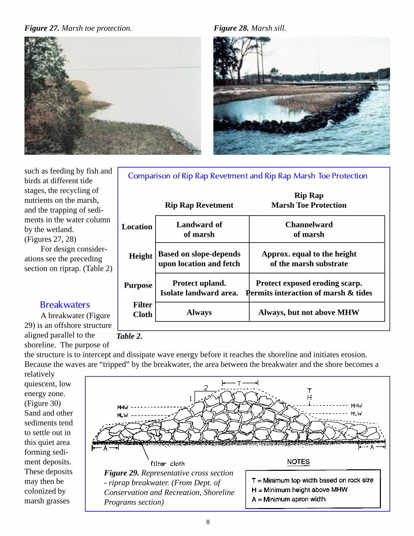
Marsh Toe ProtectionMarsh toe protection (Figure 26) is a specialized
form of riprap revetment designed to attenuate ero-sion taking place on the face of a wetland scarp. Theriprap in this case is low profile, meaning the revet-ment is less than a foothigher than the marshsurface and there is nobackfill involved. Thelow profile structureprotects the marsh facefrom further erosion butallows tidal inundation(hydrology) to continueover and through the stonerevetment. (Figures 25,26) This maintains theviability of the wetlandand allows most ecologi-cal functions to continuewithin the system. Thesefunctions include inter-community interactions
Figure 23. Revetment constructed with filtercloth. Figure 24. Established revetment.
Figure 25. Revetment provides habitat and erosionprotection.
Figure 26. Representative cross section - riprap wedge for eroding fringe marsh.(From Dept. of Conservation and Recreation, Shoreline Programs section)
8
such as feeding by fish andbirds at different tidestages, the recycling ofnutrients on the marsh,and the trapping of sedi-ments in the water columnby the wetland.(Figures 27, 28)
For design consider-ations see the precedingsection on riprap. (Table 2)
BreakwatersA breakwater (Figure
29) is an offshore structurealigned parallel to theshoreline. The purpose ofthe structure is to intercept and dissipate wave energy before it reaches the shoreline and initiates erosion.Because the waves are “tripped” by the breakwater, the area between the breakwater and the shore becomes arelativelyquiescent, lowenergy zone.(Figure 30)Sand and othersediments tendto settle out inthis quiet areaforming sedi-ment deposits.These depositsmay then becolonized bymarsh grasses
Figure 28. Marsh sill.
Table 2.
Figure 27. Marsh toe protection.
Comparison of Rip Rap Revetment and Rip Rap Marsh Toe Protection
Rip RapRip Rap Revetment Marsh Toe Protection
Landward of Channelwardof marsh of marsh
Based on slope-depends Approx. equal to the heightupon location and fetch of the marsh substrate
Protect upland. Protect exposed eroding scarp.Isolate landward area. Permits interaction of marsh & tides
Always Always, but not above MHW
Figure 29. Representative cross section- riprap breakwater. (From Dept. ofConservation and Recreation, ShorelinePrograms section)
Location
Height
Purpose
FilterCloth

9
such as saltmarsh cordgrass, Spartinaalterniflora and associated fauna such asworms, snails, crabs and shrimp to name a few.
Breakwaters are generally considered to bea “softer” approach to shoreline protection with“hardened” shorelines being those protected byvertical seawalls and riprap revetments. Thesoft approach generally refers to the use ofvegetation (see below) or a structure, whichthough it modifies the behavior of the nearshore zone, does not fix it permanently in place.The shoreline responds to natural physicalchanges such as storms, sea level rise, etc., butstill retains a measure of protection from ero-sion due to the structure.
Fixed breakwaters are generally constructed so that their top elevation is one to three feet above mean highwater. Since most erosion is sporadic, occurring during storms, the breakwater must be high enough to allowfor the storm surge. Storm surge is high water which is generally a product of low pressure systems such as“nor’easter’s” and hurricanes generated or passing over large bodies of water.
Fixed breakwaters are usually constructed ofstone or concrete rubble. They may also utilizegabion baskets which are heavy gauge wire basketsfilled with stone or sometimes other heavy materials.(Figures 31, 32, 33) Gabion baskets are wired to-gether and filled. They can be stacked and strung endto end to form a continuous structure. The advantageof the baskets is that they allow smaller (cheaper)materials to be used but once placed in the baskets atotal mass is achieved which resists movement duringstorms. (Figure 34)
Many fixed breakwaters are designed with openspaces between sections of the structure. These aretermed gapped breakwaters. (Figures 35, 36) Theyhave generally been found to form the most stable
Figure 30. Location ofoff-shore breakwater.
Figure 31. Gabion basket with stone.
Figure 32. Gabion baskets forming a gappedbreakwater.
Figure 33. Gabion basket breakwater.

10
shorelines when properly designed and constructed.The ideal situation occurs when a tongue of sand,termed a tombolo, ties each segment of breakwater tothe land and this area is further stabilized by vegeta-tion. This, of course, requires an adequate supply ofsand in the nearshore system to make up the tombolo.Sand may also be brought in from upland sources,spread and vegetated. (Figures 37, 38, 39)
Breakwaters can be floating; that is constructedof tires, logs, fabricated containers, baffles or otherfloating materials. Floating breakwaters depend ontheir width, not height, to dampen waves as they try tomove through the structure. Problems with floatingstructures range from the attachment of foulingorganisms causing the structure tosink, to the failure of anchors andtie materials during storms. (Figure40)
As with revetments, breakwa-ters should be used with filter clothand should have armor stonedesigned to resist movement whenunder wave attack during expectedstorm severity for the local area.The design wave that the structureis meant to attenuate is based ongeomorphology of the basin, fetch,water depth, exposure and otherfactors.
Environmentally, gapped breakwaters are preferred for the same reasons as described under the precedingriprap discussion but have the further advantage of allowing the shoreline to flex with changing conditions.Bulkheads and revetments are impermeable, immovable barriers which do not change with changing parameterssuch as sea level. Because a wetland or beach, located seaward of one of these structures, cannot migratelandward as sea level rises, they will eventually be covered with water and disappear.
Figure 34. Revetment made of gabion baskets.
Figure 36. Gapped breakwater.
Figure 35. Breakwater system (From Shoreline Development BMP’s,VMRC 1993.)
Figure 37. Beach before installation of offshorebreakwaters.

11
GroinsShoreline erosion is a problem that has been
around ever since man began settling adjacent tothe water and groins are one of the oldest types ofstructures used to deal with the problem. Groinsare structures placed perpendicular to the shoreline which extend into the water a prescribed distance based onthe geomorphology of the shoreline. (Figures 41, 42)
The purpose of the groin is to trap sand moving along the beach with the longshore currents. (Figure 43)When groins are working properly, sand accumulates on the updrift side of the structure acting to widen andraise the elevation of the beach. (Figure 44) Incoming waves then dissipate their energy on the accumulated sandand only attack the fastland during storm events which produce higher than normal water levels. Groins aregenerally ineffective in preventing shoreline erosion, but exhibit their most success if there is enough sand
Figure 38. Typical tombolo formation landward ofbreakwater.
Figure 41. Groin field with spur. (From Anderson,Hardaway, and Gunn, 1983.)
Figure 39. Breakwater field.
Figure 40.

12
moving in the nearshore zone that theytrap and raise the elevation of thebackshore enough that vegetation canestablish and further stabilize the shore-line.
As recognized above, groins aredependent on longshore drift and ingeneral do not achieve their intendedfunction where sand is not being trans-ported along the beach. Depending onwind direction, sand may be trapped oneither side of a groin at any given time.(Figures 45, 46) Sand may also moveonshore and offshore. The net directionof movement determines the updrift sideof the groin where the largest amount ofsediment is deposited. In the vastmajority of cases, groins deprive theimmediate downdrift shoreline of sandcausing a loss of beach or “notching,”which is accelerated erosion. Thisreaction to the groin generally disap-pears a short distance downdrift of thestructure. (Figures 47, 48)
Groins are primarily constructed oftwo materials although others havebeen tried with highly variable success.Timber tongue and groove sheetingwith pilings for stability are used alongthe majority of shorelines. These areeither driven or jetted into the bottom,with driven structures being the mostdurable. The second most popularmaterial is riprap. (Figure 49) It is
Figure 42. Groins function to trap sand.
Figure 43. Movement of sand along shoreline.
Figure 44. Groin trapping sand on updrift side. Figure 45. Groin trapping sand.

13
generally placed on a bed of geotechnical material (filter cloth) and is constructed in a manner to be free stand-ing and thus is trapezoidal in cross-section. (Figure 50)
In general, groins should be designed to mimic the beach and should be higher at their landward end inorder to build the elevation of the backshore. Length is not critical in most cases, and commonly need only beextended ten to twenty feet beyond mean low water.Groins which are too long interfere with the normalmovement of sand in the nearshore area and maydeprive downdrift beaches of sand needed to maintainequilibrium with erosion forces. Low-profile is therecommended design for groins of either timber orstone. Low-profile requires the channelward end ofthe groin have an elevation no greater than that ofmean low water (Figures 51, 52). This allows sand tobegin bypassing the groin more quickly once the groincell has filled, lessening the period of interruptedlongshore sand movement and minimizing to adegree, the adverse effects of the groin to downdriftshorelines. If groins are considered desirable in agiven situation, downdrift sand deprivation can be
Figure 46. Groin with spur. Figure 47. Downdrift erosion at end of groin field.
Figure 48. Beach erosion due to groins. Figure 49. Riprap groin trapping sand.
Figure 50. Riprap groin placed on filter cloth.

14
minimized by filling the groin cellartificially from an upland sandsource.
Another method which can beused in specific situations to minimizedowndrift erosion due to groins is theattachment of a spur (Figures 41, 53,54, 55, 56) The spur is generally ashort (12-15 feet) structure of thesame design as the groin which isattached to the downdrift side and extends out from the groin parallel to the shoreline. The spur may be placedanywhere along the groin between mean low water and the channelward end, depending on specific shorelinegeomorphology. Spurs generally cause the accumulation of sand landward of their location, helping to mini-mize downdrift effects of the groin.
Provided that there is sufficient sand in the nearshore zone for groins to be effective, the most importantadditional structural and design considerations are two:
1. Groins must be securely fastened to the uplands so that sand cannot get around them at their shorewardends. Many groins fail when erosion occurs so quickly that the landward end of the groin is exposed
Figure 52. Low profile groin design. Figure 53. Sand accumulated on updrift side of groin.
Figure 51. Low profile groin. (From Shoreline DevelopmentBMP’s, VMRC, 1993.)
Figure 54. Spur prevents erosion on downdrift side ofgroin.
Figure 55. Groin with spurs.

15
before the structure has enough time to build up sand and stabilize the beach. If rapid erosion is aconcern, riprap may be placed adjacent to the point where the groin meets the fastland. (Figure 57)
2. Groins must be solid structures which only allow passage of sand overtop of them or around theirchannelward ends. Groins constructed of used tires, well casings or other porous materials are ineffec-tive because the sand passes through them.Old groins with loose or missing timbers failfor the same reason.
JettiesJetties are structures very similar to groins in
design and construction. The difference between thetwo is that whereas groins are used on and attached toany suitable reach of shoreline, jetties generally defineand protect inlets and/or harbor entrance channelsfrom shoaling by preventing sand from accumulatingin the channel or moving across the channel withlongshore currents. (Figures 58, 59) Jetties may alsofunction to dampen waves moving across an inlet or
Figure 56. Groin with spur. Figure 57. Groin field flanked by erosion.
Figure 58. Riprap protecting a channel.
Figure 59. Riprap jetty and adjacent wetland. Figure 60. Stone jetties protect channel.

16
entrance channel, making navigation easier and safer.(Figures 60, 61)
Vegetative ControlAlthough not a structural option, per se, using
vegetation to control shoreline erosion can be veryeffective in the right circumstances and has the addedbenefit of providing highly beneficial habitat tomarine and freshwater systems. (Figure 62) Vegeta-tive control may be used by itself or in concert withconventional structures such as gapped breakwaters oroffshore sills.
When vegetation, usually some type of wetlandor submerged aquatic vegetation (SAV), establisheson a shoreline, its root and rhizome system serves tostabilize the existing substrate in place and the sub-aerial shoots baffle water movement causing sedimentparticles to be deposited along the shoreline. This action helps to build and maintain the intertidal and subtidalzone, minimizing the severity of erosion in many cases.
Many types of fringe marshes can be very effective as shoreline stabilizers, with a width of eight feet orgreater width on the shoreline generally being highly effective. Not all situations are suitable for vegetativecontrol however. Research indicates that shorelines with less than a mile of fetch generally can be stabilizedwith wetland vegetation. Freshwater marshes do not generally have the thick root and rhizome systems thatbrackish and salt marshes have, so they must be significantly wider to have the same wave baffling effectivenessthat their saltwater cousins have.
Marshes can be established on suitable shorelines using either transplants from established wetlands ornursery grown stock. (Figure 63) In either case some knowledge of wetland plants is necessary along withinformation on planting elevations (the primary factor in successful establishment), fertilization requirementsand plant spacing. This information is available from the Virginia Institute of Marine Science, the Departmentof Conservation and Recreation and a number of publications available from libraries and bookstores. (Figures64, 65)
Many waterfront property owners reject the idea of controlling erosion with marsh plantings as infeasiblebecause the wetlands cannot be counted on to inhibit erosion on a long term basis. Many fringe marshes, onceestablished however, may last at least as long as the design life of the average wood bulkhead (i.e. 20 years).
Figure 61. Single jetty protecting channel. Figure 62. Vegetated wetland protecting shorelinefrom erosion.
Figure 63. Planting on 18” center grid.

17
(Figure 66) When one considers the lower cost, reduced adverse impact and positive environmental contributionof this option, it should be considered a viable alternative to structural erosion control. It bears repeating how-ever, that vegetative control should only be considered for shorelines with less than a mile of fetch. (Figure 67)A good indicator of potential success is whether wetlands exist in other sections of the same reach of shoreline.
Figure 64. Planted wetland. Figure 65. Planted wetland shown in Figure 66 afterone growing season.
Figure 67. Bulkhead reflecting wave energy.Figure 66. Fringe marsh protecting shoreline.

18
GlossaryAnchor piles These are anchors, usually vertical piles driven into the ground, on the landward side of
the bulkhead, to which the bulkhead is tied by tiebacks or tie-rods (commonly calleddeadmen).
Armor This refers to the larger stone used as the outer layers of a revetment which is directlyexposed to waves.
Breakwater A breakwater is an offshore structure which is aligned parallel to the shoreline. A fixedbreakwater refers to one generally constructed of stone or gabion baskets (wire baskets ormattresses which are filled with stone), placed on the bottom. Floating breakwatersshould be firmly anchored and may be constructed of tires, logs, specially fabricatedboxes and baffles, or other floating materials.
Buried toe This is the practice of trenching in the seaward toe of a riprap structure to help preventscour and shifting of the structure.
Core The core is the smaller stone used as the base of the revetment which is not directlyexposed to waves.
Fetch Fetch is the distance that wind blows over water prior to its reaching a shoreline.Generally it is used as an estimate of potential wave energy or stress the shorelinemay expect.
Filter cloth Filter cloth is the synthetic textile placed between sheeting and backfill which preventssoil loss but is water-permeable.
Groin This is a structure that is perpendicular to the shoreline and extends into the water. Theyfunction in trapping sand moving in the along-shore currents.
Jetting Jetting is a method of sinking structures in substrate where high pressure water “washes”the structure down and the hole refills with sediment as the pressurized water is cut off.
Jetty As with groins, jetties are linear structures placed perpendicular to the shoreline and crossthe intertidal zone to deeper water. They function to intercept sand moving along theshoreline and protect channels and inlets from shoaling and wave energy.
Low-profile This is a recommended design for either timber or stone groins, in which the elevation ofthe channelward end of the groin is no greater than that of mean low water. This allowsthe sand to bypass the groin more quickly once the groin cell is filled, lessening theinterruption of sediment movement to downdrift shorelines.
Marsh toe This is a low-profile rock structure placed channelward of a marsh, usually being placedprotection directly against an eroding scarp.
Return walls These are walls located at each end of the bulkhead and shoreline, approximatelyperpendicular to the bulkhead and shoreline, which tie the bulkhead into the upland andprevent the bulkhead from being flanked.
Revetment A revetment is a sloped structure consisting of multiple layers of stone or other materialplaced along a bank.
Riprap Riprap is the stone used to build a revetment. Frequently, the structure itself is calledriprap.

19
Screw anchors Screw anchors refer to another anchoring method that consists of rods that screw intothe upland.
Sill Sill is a continuous low-profile breakwater structure.
Spur Spurs are attached to the downdrift side of the groin and oriented perpendicular to thegroin, and parallel to the shoreline. The spur may be aligned anywhere between MLWand the channelward end of the groin. The purpose is to prevent characteristic erosion ofsand immediately downdrift of the groin.
Tiebacks These are rods used to connect the bulkhead to the land anchor pile or deadmen (usuallythe horizontal piles connected to the anchor pile).
Tombolo This is the name given to the build-up of sand landward of gapped breakwaters.
Up- & down drift Updrift and downdrift refer to longshore drift, or the movement of sediment along theshore. Sediment may move in both directions along a particular shoreline. The netdirection of movement determines the net accumulation of sediment by a groin. Groinsnecessarily deprive downdrift shorelines of their sand supply, worsening any existingerosion problems.
Vegetative control Vegetative control is the use of wetlands vegetation to deter erosion, either alone or inconcert with an offshore breakwater or sill. Vegetation may be planted or allowed tocolonize naturally.
Whaler Whaler refers to a structural member of a wood bulkhead or groin which runshorizontally between pilings and braces the sheeting.
Literature CitedAnderson, G.L., C.S. Hardaway, and J.R. Gunn. 1983. Beach response to spurs and groins. In Coastal Structures
1983. Ed. J.R. Weggel. Amer. Soc. of Civil Engineers. New York, New York. pp 727-739.
Virginia Marine Resources Commission. 1993. Shoreline Development BMP’s. 54 pp.
Suggested Reading ListHardaway, Scott and Gary Anderson. 1980. Shoreline erosion in Virginia. Educational Series No. 31. VIMS Sea
Grant Advisory Service.
U.S. Army Corps of Engineers. 1981. Low cost shore protection...a property owner’s guide. Norfolk, Virginia.159 pp.
U.S. Army Corps of Engineers. 1990. Chesapeake Bay shoreline erosion study. Feasibility report.Baltimore and Norfolk Districts. 111 pp.